

Page 1

REEL MOWER GRINDER
RG5500
SPIN / RELIEF
This book consists of three manual s:
The OPERATO RS MANUAL in ENGLISH w hich contains all the information on operating and do ing routine
daily maintenance on this equipment.
The ASSEMBLY and SERVICE MANUAL which is used by the maintainence department to install the
equipment and to do all maintenance except routine daily maintenance.
The OPERA TORS MANUAL
(REV. 6/20/201 1)
in FRENCH
which is the same as the English version only translated into
1
French.
Page 2

DEALER PREPARATION/INSTALLATION CHECK LIST
Frontier RG5500 Spin/Relief Reel Mower Grinder
THIS CHECKLIST IS TO REMAIN IN OWNER’S MANUAL
It is the r esponsibility of the dealer to complete the procedures listed bel ow , then
review this checklist wi th the customer upon the delivery or the sale of this equipment.The ins tallation
trainin g goes over the basic op erational functi ons of the equipment. To ensure adequate train ing, we
require that the following i tems are r eviewed by your John D eere Dealer . Pleas e check off to ensure
that you under stand the follow ing items before the instal lation tr aining i s com plete:
1. Equipm ent i s c ompl etel y as sem bl ed
2. All s hields ar e in place and i n good condi tion.
3. All decals i n place and r eadable. ( See pages)
4. Overall c ondition good (i .e. paint, wel ds, electr ical)
5. V eri fy there is suffici ent electr ical power to oper ate
the machine.
6. Review Operators, Assembly & Ser v i ce Manuals,
and any addi tional tr aining m ateri al if availabl e.
Dealer 's Signature
Purchaser's Si gnature
Safety
IMPORT ANT SA FETY MESSA GE FOR OWNERS/OPERAT ORS OF REEL GRINDERS
Safety is a primary concern in the design, manufacture, sale,
and use of reel grinders. As manufacturer of reel grinders, we
want to confirm to you, our customers, our concern for safety. We
also want to remind you about the simple, basic, and common
sense rules of safety when using a reel grinder. Failure to follow
these rules can result in severe injury or d eath to operators or
bystanders.
It is essential that ever yone involved in the assembly, operation,
transport, maintenance, and storage of this equipment be
aware, concerned, prudent, and properly trained in safety.
Always use proper shielding as specified by the manufacturer.
Our current production machines include, as standard
equipment, guards or shields for the grinding wheel, safety
signs and an operators manual. Never bypass or operate the
machine with any of the guards or safety device removed.
Read and fully underst and all t he safety pr acti ces discussed
on pages 4 and 5 of this manual. All saf ety r ules must be
understood and foll owed by anyone who works wi th r eel
grinders.
7. Review proper posi tioni ng of reel
8. Explain use of reel grinder rel ief mechanis m
9. Review traverse proxi mity switch posi tioni ng
10. Ex plain use of reel grinder ali gnment gage
11. Explain reel gr inder s pin speed vs. quali ty
12. Di s cus s reel gr i nder s et- up char t in manual
13. Review Gener al Mai ntenance
Before operating a reel grinder, an operator must read and
und erstand all o f the info rmation in the ow ner’s man ual and in
the safety signs attached to the product. A person who has not
read or understood the owner’s manual and safety signs is not
qualified to operate the unit. Accidents occur often on machines
that are used by someone who has not read the owner’s
man ual a nd is no t f amiliar with the eq uipm ent . If yo u d o not have
an owner’s manual or current production safety signs, contact
the manufacturer or your dealer immediately.
Reel grinders are designed for one-man operation. Never
operate the grinder with anyone near, or in contact with, any part
of the grinder. Be sure no one else, includ ing bystanders, are
near you when you operate this product.
Follo wing th ese simple, b asic safety ru les, as well as o thers
identified in the owner’s manual and in product safety signs, will
help minimize the possibility of accidents and increase your
productivity in using this product. Be careful and make sure that
everyone who operates the grinder knows and understands that
this is a very powerfu l piece of m achinery, and if used
improperly, serious injury or death may result. The final
responsibility fo r sa fety r ests with the operator of this machin e.
2
Page 3

TO THE DEALER:
Assembly and pr oper inst allation of this pr oduct is the responsi bility of the John Deere dealer . R ead manual
instructi ons and s afety rules. M ake sur e all i tems on the Pr epar ation Chec k List in the Oper ator’s M anual are
complet ed before releasi ng equi pment to the owner.
TO THE OWNER:
Read this manual before operati ng your Fr ontier equipment. Keep this m anual handy for ready
reference. Requir e all operators to r ead this manual c arefully and become acquai nted with all
adjustments and operating pr ocedures before attem pting to operate the equipment. Replac ement
manuals can be obt ained from you sel ling dealer.
The equipmen t you h ave purc hased has been careful ly engi neered and manufacture d to provi de
dependable and satisfactory use. Like all mechani cal produc ts, it will requir e cleani ng and upkeep.
Lubricate the unit as specified. Pl ease observe al l safety information in this m anual and safety
decals on th e equipment.
For servi ce, your authorized John Deer e dealer has trained mechani cs, genuine Fronti er servic e
parts, and the necessary tools and equipment to handle all of your servic e needs.
Use only genuine Frontier servic e parts.
3
Page 4

SAFETY INSTRUCTIONS
Safety Awareness Symbols are inserted
into this manual to alert you to possible
Safety Hazards. Whenever you see these
symbols, follow their instructions.
!
The Warning Symbol identifies
special instructions or procedures
which, if not correctly followed,
could result in personal injury.
1. KEEP GUARDS IN PLACE and in working
order.
2. REMOVE WRENCHES AND OTHER
TOOLS.
3. KEEP WORK AREA CLEAN.
4. DON'T USE IN DANGEROUS ENVIRONMENT.
Don't use Grinder in damp or wet locations.
Machine is for indoor use onl y. Keep work area
well lit.
5. KEEP A LL VISITORS AW AY . All visitors
should be kept a s afe distance from w or k ar ea.
6. MAKE WORK ARE A CHILD-PROOF with
padlocks or m as ter s wi t ches .
The Cauti on Sym bol identifies special
instructions or procedures which, if not
strictly observed, could result in damage
to or destruction of equipment.
12. DON'T OVERREACH. Keep proper footing and
balance at all times .
13.MAINTAIN GRINDER WITH CARE . Fo llow
instructi ons in Ser vic e M anual for lubr icati on and
preventiv e mai ntenance.
14.DISCONNECT PO WER BEFORE SERVICING,
or when changing the gr inding w heel.
15.REDUCE T HE RISK OF UNINTENTIONAL
STARTING. Make sure all switches are OFF
before plugging in the grinder.
16.USE RECOMMENDED ACCESSORIES. Consult
the manual for recom mended acces sories . Usi ng
improper access ories may cause ris k of personal
injury.
7. DON'T FORCE THE GRINDER. It will do the job
better and safer if used as specified in this
manual.
8. USE THE RIGHT TOOL. Don't force the grinder
or an attachm ent to do a j ob for which i t was not
designed.
9. WEA R PROPER A PPAREL. Wear no l oos e
clothing, gloves, neckti es, or j ewelr y which m ay
get caught in moving par ts . Nonslip footwear is
recommended. Wear protecti ve hair coveri ng to
contain long hai r.
10. ALW AYS USE SA FETY GLASSES.
11. SECURE Y OU R WORK. Make c ertain that the
cutting unit is securel y fastened with the clam ps
provided before ope rating.
17.CHECK DAMAGED PARTS. A guard or other
part that is damaged or will not perform its
intended function shoul d be properl y repai red or
replaced.
18.KNOW YOU R EQU I PMENT. Read this manual
carefully. Learn its applic ation and li mi tations as
well as specific potential hazards.
19.KEEP ALL SA FETY DECA LS CLEA N AND
LEGIBLE. If safety decals become damaged or
illegibl e for any reason, r eplace i mmedi ately.
Refer to replacement parts illustrations in Service
Manual for the proper l ocation and par t number s
of safety decals.
20.DO NOT OPERATE THE GRINDER WHEN
UNDER THE INFLUENCE OF DRUGS,
ALCOHOL, OR MEDICAT ION.
4
Page 5

SAFETY INSTRUCTIONS
IMPROPER USE OF GRINDING WHEEL MAY CAUSE
BREAKAGE AND SERIOUS INJURY.
!
Grindi ng is a safe operat ion if the few basi c rul es l isted bel ow ar e follow ed. Th ese ru les ar e based on mater ial
contained in the ANSI B7.1 Safety Code for "Use, Care and Protection of Abras ive Wheels". For your safety ,
we suggest you benefit from the experi ence of others and follow these r ules.
DO
1. DO always HANDLE AND STORE
wheels in a careful manner.
2. DO VISUALL Y INSPECT all w heel s before
mounting for poss ible dam age.
3. DO CHECK MACHINE SPEED against the
establis hed maxim um safe operating speed
marked on wheel .
4. DO CHECK MOUNTING FLANGES for equal
and correct di ameter.
5. DO USE MOUNTING BLOTTERS when supplied
with w heels.
6. DO be sure WORK REST is properly
adjusted.
7. DO always USE A SAFETY GUARD C OVER I NG
at least one-half of the grinding wheel.
DON'T
1. DON'T use a c racked wheel or one th at HAS BEEN
DROPPED or has become damaged.
2. DON'T FORCE a wheel onto the machine OR
ALTER the si ze of the m ounti ng hole- -if w heel w on't
fit the machine, get one that will.
3. DON'T ever EXCEED MAXIMUM OPERATING
SPEED establ ished for the wheel.
4. DON'T use mounting flanges on whic h the bear ing
surfaces ARE NOT CLEAN, FLAT AND FREE OF
BURRS.
5. DO N' T TI GH TE N t he m ounti ng nut EXCESSIVELY.
6. DON'T grind on the SIDE OF TH E WH EEL (see
Safety Code B7.2 for exception).
7. DON'T star t the machine until the WH EEL GU A RD
IS IN P LACE.
8. DO allow NEWLY MOUNTED WHEELS to run at
operating speed, with guard i n place, for at least
one minute before gr inding.
9. DO always WEAR SA FETY GLA SSES or som e
type of eye protection w hen grindi ng.
A VOID INHALATION OF DU ST gener ated by gri nding and cutting oper ations. Exp osure
to dust may cause respiratory ailments. Use approved NIOSH or MSHA respirators,
safety glasses or face shields, and protec ti ve c lothi ng. Pr ov ide adequate ventil ation to
eliminate dust, or to maintain dust level below the Threshold Limit Value for nuisance
dust as classi fied by OSHA.
8. DON'T JAM wor k i nto the w heel .
9. DON'T STAND DIRECTLY IN FRONT of a
grinding wheel whenever a grinder is started.
10. DON'T FORCE GRINDING so that motor slows
noticeably or work get s hot.
5
Page 6
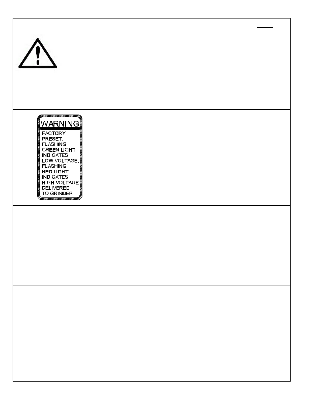
TABLE OF CONTENTS
This machine is intended for grinding the reel of reel type mower units ONLY.
Any use other than this may cause personal injury and void the warranty.
To assure the quality and safety of your ma chine and to maintain the warranty,
you MUST use original equipment manufactures replacement parts and have
any repair work done by a qualified professional.
ALL operators of this equi pment mus t be thoroughly trained BEFORE operating
the equipment.
Do not use compressed air to clean grinding dust from the machine. This dust
can cause personal injury as well as damage to the grinder. Machine is for
indoor use only. Do not use a power washer to clea n the mac hine.
Low V oltage Relay
The grinder is equi pped with a high-low volt age relay
which is factory pr eset at 100-140 V AC. I f the power
supply line does not del iver 100-140 VAC power under
load, the relay w i ll open and tr i p out the starter. I f this
occurs, your pow er suppl y l i ne is i nc or r ect and must be
correct before pr oceeding further with the gri nder.
!
TABLE OF CONTENTS
Safety Instructions ................................................................................................................. Page 4 - 7
Daily M aintenance ................................................................................................................. Page 6
Getting to Know Your Grinder ................................................................................................ Page 8 - 14
Operating Instructions............................................................................................................ Page 15 - 27
Reel Setup Chart ................................................................................................................... Page 28
DAILY MAINTENANCE BY THE OPERATOR
On a daily basis, clean the machine by wiping it off.
On a daily basis, remove all grinding grit from the grinding shaft, traverse shafts, and tooling
bar area.
On a daily basis, inspect the machine for loose fasteners or components.
Contact your company's Maintenance Department if damaged or defective parts are found.
DO NOT U SE C OMPRESSED A IR TO CLEAN
GRINDING DUST FROM GRINDER.
!
6
Page 7

SAFETY INSTRUCTIONS
PLEASE TAKE SPECIAL NOTE OF THE FOLLOWING WARNING DECALS LOCATED ON
THE GRINDER.
GRINDING WHEEL RPM
GENERAL INFORMATION
SHARP OBJECTS
ELECTRICIT Y
Label Sheet
(English and S panish)
Part Number 5NT155301
(English and French)
Part Number 5NT155302
7
Page 8

GETTING TO KNOW YOUR GRINDER
SPECIFICATIONS
Tr aversing Sw itches Solid st ate, non-contacting prox imity swi tches.
Overall Width 71" [181 cm]
Overall Height 69" [175 cm] w i th door cl os ed, 87" [221 c m] w i th door open
Overall Depth 42" [107 cm]without wor kst ation, 79" [201 cm] w ith optional wor kst ation
Weight 1450 lbs. [658 kg] 1650 lbs shipping weight [748 kg]
Base C onstru ction Precision heavy duty reinforced w elded steel bas e
Carriage R ails Precision Gr ound, Hardened S teel - 1.000 Di a. [25.4 mm]
Grind H ead M otor 1HP AC Motor, 3450 RPM
Spin M otor .20 HP Fan C ooled V ari able S peed D C M otor
Sound Lev el More than 75 Dba, Less than 95 Dba
Auto Tr averse Belt driven with easy to engage clamp system
Control System *Safety grind motor and spin dr ive door interrupt s witc hes
*Reversible S pin drive for variable speed Spin or variable torque relief functions
*V ariable s peed traverse contr ol.
Options: *Manual Winch and Boom Kit, Electr ic Winch and Boom Kit or Lift Platform.
8
Page 9

GETTING TO KNOW YOUR GRINDER (Continued)
CONTROL PANEL COMPONENT IDENTIFICATION
Review the following c ontrol panel component descr iptions before proc eeding wi th the i nstructi ons
SYSTEM START PUSHBUT TON
The green pushbutton is the system star t swi tch. Pushi ng
it will engage the magnetic star ter and power the control
panel. The magnetic s tarter will not engage unless the
emergency stop pushbutton i s pulled out and the gri nding
motor switc h and spi n m otor s wi tc h ar e tur ned off.
GRIND SELECTOR SWITCH
Variable speed spin
Switc h m ust be up to perform
s pin gr i ndi ng oper ati ons .
Variable Torq ue Relie f
Switc h m ust be down to perform
relief grinding operations .
SPIN DRIVE ROTATION SWITCH
Forward / Off / Reverse
This switch reverses the direction of the spin
drive motor.
IMPOR T ANT: Because the spin drive motor
c an be flippe d on the hor izontal adj ustm ent
arm, the direction m ay be opposite of what
is shown on the decal.
SPIN SPEED POTENT IOMETER DIAL RPM
Adjust s the s peed of reel r otation when you
have the grind selector switch set at variable
speed spin.
GUARD DOORS MUST BE S HUT FOR SPIN
DRIVE TO OPERATE.
9
Page 10

GETTING TO KNOW YOUR GRINDER (Continued)
PUSH-PULL EMERGENCY STOP BUTTON
Push in to cut all pow er to the control panel functions .
This removes power from all motors, including the
grinding motor, traverse motor, spin motor, etc. To
restore power, pull up on button and press the Start
button.
SPIN MOT OR SWITCH On / Off
Tur n the S pin M otor on and off.
GUARD DOORS MUST BE SHUT FOR GRIND
!
MOTOR TO OPER ATE.
RELIEF TORQUE DIAL
Adjust s the Spin Dri ve Motor tor que (the torque holding
the reel blade to the relief finger) when Gr ind Selector
Switch is set at var iable T orque R elief.
!
GRINDING WHEEL MOTOR SWITCH On / Off
T urn the Grindi ng Wheel Mo tor on a nd off.
GUARD DOORS MUST BE SHUT FOR GRIND
MOTOR TO OPER ATE.
TRAVERSE MOTOR SW ITCH
Tur ns the traver se dri ve motor ON /OFF.
TRAVERSE SPEED POTENTIOMETER
DIAL - FT / MIN
Adjust s the speed of the left & rig ht
movement of the Grindi ng wheel.
TRAVERSE REVERSE SWITCH
Reverses the di recti on of the grindi ng
head if pushed when the head is moving.
10
Page 11

GETTING TO KNOW YOUR GRINDER (Continued)
FRONT AND REAR MOWER MOUNTING
The mow ing uni t s hould b e placed in t he mac hine w ith
the rear roller on the table and front roller held in the
front tooling. The front tooling can be moved side to
side along t he too ling b ar s o they can b e posi tion ed as
far ap art as neces sar y to acco mmoda te al l reel wi dths.
Decals on the tooling bar make i t easy to position the
tooling based on the width of the reel. To move the
tooling, loosen the knob located at the front of the
tooling base and slide tooling along the tooling bar . The
tooling should be located as close to the frame as
possible leaving the maximum room to use the
position gauge (the gauge will be discussed in the
alignment section). The horizontal position is attained
by using the hand wheel located at the front of the
tooling. If yo u are gri nding a Quick Adjus t mow ing unit
(QA7 or QA5), use the decals loc ated on the tooling to
quickly position the reel. There are two positions for
each reel depending on how the front roller is mounted.
See FIG 2.
If you are using the all- pos it ion brac kets , the ver ti cal
and horizontal posi ti on c an be adj usted by l ooseni ng
the knobs located on the side of the tooling and
moving to a new set of pins.
Verify that the reel is positioned properly for the spin
wheel and relief wheel by checking the travel limits,
both wh ee ls will need to have clearance to come off
the reel on both sides. Checking during setup will
eliminate the need for major adjustments and
alignments when going from spin grinding to relief
grinding. W hen the mower is in place lock it into
posit ion by tigh tening all kno bs. L ift the rea r r oller onto
the angled bracket and clamp the roller firmly by
squeezing the clamp handl e.
REEL POSITION
The reel should b e positioned so that it i s at a o ne o’clock
or 30° angle position in reference to the grinding wheel.
See FIG 3. If the all - pos i ti on br ack ets ar e used tr y to
position the unit so that the bottom of the reel is
between 1.50-2.00" [38-51MM] off the table. W hen
using the roller mount styl e tooling try to maintain the
one o’clock positi on and check for clear ance between
the reel and grinding wheel. Verify that the proper relief
angle can be achieved with this setting and make
any adjustments i f necessary.
FIG . 1
QA5 AND QA7 REEL
LOCATION DECAL.
TOOLING POSITION
DECAL
FIG . 2
If you are grindi ng a QA7 or QA5 r eel usi ng the r ol l er
style mounts, use the decal s located on the tooli ng to
obtain the optimal posi tion to grin d the reel. See fIG 2
FIG . 3
11
Page 12
GETTING TO KNOW YOUR GRINDER (Continued)
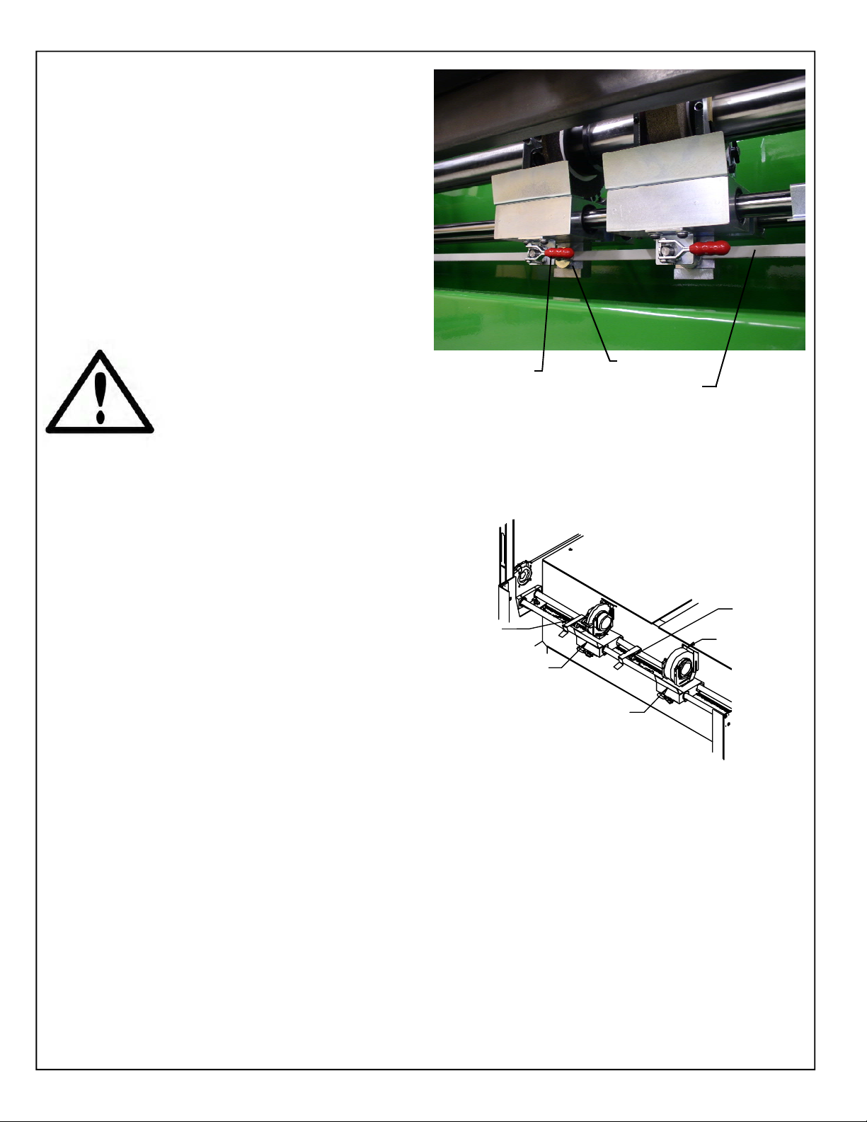
TRAVERSE ENGAGEMENT AND RELEASE
The belt that drives the relief and spin hubs left and
right can b e engaged and r eleased by flipping the c lamp
located on the bottom of the grinding head assemblies.
Moving the lever t o the left will engage the belt and
moving it to the right will disengage the belt. The tip
can be adjusted if necessary to i ncrease or decreas e
the tension on the belt. See adjustments in the
service m anual for m or e detai l s.
THE BELT CLAMP TIP IS
ADJUSTED AT THE FACTORY TO
ALLOW THE BEL T TO SLIP IF THE
HUB COMES IN CONTACT WITH
SOME THING. CAUTION SHO ULD
BE USED WHEN ADJUSTING THE
TIP. IF THE CLAMP IS OVERTIGHTENED, THE BELT WILL
NOT SLIP WHICH MAY CAUSE
DAMAGE TO THE MACHINE OR
REEL.
TRAVERSE BELT
ENGAGEMENT
LEVER
CLAMP TIP
TRAVERSE BELT
FIG .4
TRAVERSE PROXIMITY SWITCHES
T wo m ovabl e pr oxi mit y sw itches deter min e the lef t and
right lim it s of grinding head assembl y . An LED on the
switch li ghts when the grindi ng head gets close to the
head of t he pr oxim ity swi tch. The se nsor s ar e m ount ed
in the Proximity Brackets located on the traverse shafts.
The brackets can easil y be slid along the shafts for quick
and easy travel limit adjustments. When switching from
the spi n mode to the r elief mo de, the br acket s will need
to be lifted off the shafts and snapped back on the shafts
in the proper pos ition.
SPIN/RELIEF GRINDING HEAD
This gri nder is equi pped wi th separate spi n and rel ief
grinding wheel s. When the setup is done proper ly the
reel will be only need to be positioned and aligned once
for both cycles. The spin wheel i s located on the ri ght
side of the machine and is wider than the relief wheel.
Move the wheel that is not being used as far to that side
as possible to give the maximum amount of room to
setup and operate the machine. The proximity
sensors must be moved so that the wheel in use is
between the two sensors. Make sure that the wheel
that is not in use is not engaged to the drive belt.
TRAVERSE
LEFT LI MI T
PROXIMITY
SENSOR
RELIEF GRINDING
WHEEL & HUB
TRAVERSE
RIGHT LI MIT
PROXIMITY
SENSOR
DUST
DEFLECTOR
SPIN GRINDING
WHEEL & HUB
FIG . 5
12
Page 13

GETTING TO KNOW YOUR GRINDER (Continued)
RELIEF ANGLE A DJU STM EN T
Rotating the finger system around the grinding wheel wi ll
change the relief angle. By loosening the large ratchet
handle the finger system can be rotated to achieve the
factory angles, or whateve r angle you select. See FIG. 6.
By r otati ng th e finge r for war d the rel ief angle wi ll decr ease
and rotating it rearward the relief angle will increase.
Retighten the ratchet handle when adjustment i s correct .
RELIEF WHEEL DIAMETER ADJUSTMENT
As the wheel wears, the finger system will need to be
adjusted to maintain the correct gap between the f ixed
finger and wheel. To move the finger system loosen the
small ratchet handle. See FIG. 6. The gap between the
fixed finger and the grinding wheel should be between
.06" [1.5 m m] and .18" [4.6 mm] dependi ng on the amou nt
of existin g relief on the reel . Retighten the rat chet handle
after the adjustment i s made.
INDEX FINGER ADJUSTMENTS
The R elief Assemb ly incl udes tw o fing ers. S ee FIG. 6. The
Fixed Relief Finger hold the blade in position during the
relief grind process. The Movable Index S top Finger moves
from the Relief Finger Side (back side) of the reel blade
when traversing from right to left, to the grinding wheel
side (front s ide) of the reel blade when traver sing from left
to right. T he indexing finger all ows the gr inder to index to
the next blade automatically during the relief grind.
Improper adjustment of the relief f ingers assembly may
result in a bad grind or possibly damage to the reel or
machine.
INDEX FINGER
STOP POSITION
KNOB
W HEEL DIAMETER
ADJUSTMENT
HANDLE
RELIEF ANGLE
ADJUSTMENT
HANDLE
FIXED FINGER
INDEX STOP
PIN
MOVABLE
INDEXI NG
FINGER
FIG . 6
The Index Finger Stop Position Knob adjusts where the
Index finger stops when the reel blade indexes. See FIG . 6.
Proper positi on of this st op is cr itica l to allow the reel blade
to smoothly transition from the Index Finger to the Fixed
Finger.
IMPORTANT! After adjusting the Index Finger Stop
Position Knob there should be 1/32" [0.8 mm] clearance
between the index finger and the reel blade when you push
on the index finger . This will allow the Fixed Relief Finger
to guide the reel blade during the relief grind cycle. The
Reel blade should never be riding on the Index Finger
when grinding.
The Index Stop Pin is height adjustable. It should be
adjusted to catch the reel blade and still leave enough
clearanc e to the reel spider after the r elief i s gr ound to the
depth required.
There is a forward position stop on the Finger system
located near the pivot poi nt of the I ndex Finger . T his w ill only
need to be adjusted if there is a clearance issue with the
finger when it travels forward. See FIG 7.
13
INDEX FINGER
FORWARD STOP
POSITION
SETSCREW
FIG . 7
Page 14

GETTING TO KNOW YOUR GRINDER (Continued)
ALIGNMENT GAUGE
A properly ground reel should be cylindrical. All taper
must be ground out of the reel. To ensure the reel will
be ground correct ly it MUST be aligned pr ecisely prior
to grinding. The digital alignment gauge is used for
accurate reel setup. The gauge is used for setting the
horizontal alignment and checking for taper within
thousands of an inch. The digi tal gauge al l ows y ou to
measure o ne end of the reel by extending the slide rai l
until you make c ontact w ith the cen ter shaft of the reel.
See FIG . 8. By measuring at the far left and the far right
on the center shaft you can adjust the horizontal
alignment using the front tooling adjustment knobs until
the alignment is w ithin .005 i nches [.13mm ].
When this is completed, you can then res et the gauge
to zero on the center shaft, retract the gauge slide
and measure the outer surface of a reel blade. By
comparing the readings on the left side of the reel to
the right side of the reel, you can determine exactly how
much taper you have in the reel. Compensating for
taper will be explained later in the grindin g proced ure.
INDICATOR SLIDE RAIL
IN / mm
REEL CENTER SHAFT
ZERO RESET
ON/OFF
FIG. 8
NOTE: The gauge can be set for both inch and metr ic
readout.
14
Page 15

OPERATING INSTRUCTIONS
PREPARE MOWING UNIT FOR SHARPENING
Always follow the procedures specified in the cutting
unit manual w hen pr epar i ng the uni t for shar peni ng. It
is recommended that the reel to be sharpened is
thoroughl y cl eaned . Remo ve the whee ls an d bed bar, if
possible, from the reel. The bedknives should be
sharpened when the reel is sharpened. Inspect,
adjust and/or r epl ac e any w or n or dam aged bear i ngs.
Mak e sure the ree l beari ngs are in go od wor king con dition and adjusted properly so the reel turns easily by
hand.
Becaus e thi s gri nder m ounts the r eel u sing the reel rear
roller and front roller if applicable, the bearings in the
rollers must be in good repair with no free play. The
front and rear rollers must be properly aligned
parallel to the reel prior to grinding.
REELS WITH EXCESS TENSION ON THE
BEARIN GS WILL BE EXTREMELY DIFFICULT
TO SPIN GRIND AND COULD CAUSE
DA MAGE TO THE REEL OR THE SPI N D RI VE
MECHANISM ON YOUR GRINDER. NO
MORE THAN 25. IN. LBS MAXIMUM TORQUE
!
LOAD TO ROTATE THE REEL IS ALLOWED
OR DAMAGE TO THE SP IN DRIVE COULD
OCCUR.
FIG. 9
LIFTING REEL INTO POSITION
The RG5500 grinder does not com e standar d wi th a l ift
device. If the facility does not have a lift, it is r ecommended
that the winch and b oom ki t or R ear Li ft Platform is us ed.
.
WINCH & BOOM KIT
The Winch & Boom kit mounts to the back right side of
the cabinet. When using the W inch & Boom, position
the cutting unit behind the machine and secure the
spreader bar to the cutti ng unit. Use the winc h to li ft the
unit and swing the reel into the working area of the
machine. (Refer to m anual in kit for further i nstructions.)
See FIG. 9 - Av ailable wi th a Manual or El ectric w inch.
REAR LIF T PLA TFOR M
The Rear Lift T able is a portable platform that can be used
to raise the r eel up l evel to the gr i nder. The r eel can be
rolled onto the platform with the front of the reel facing the
front of the grinder. With rear roll er cl am p r em oved the
reel can be roll ed fr om t he pla tform int o th e ma chin e from
the rear. The Workstation uses a 12V rechargeable
system to power the platform and can be moved around
the facility on the 4 caster wheels .
See FIG . 10
FIG. 10
15
Page 16
OPERATING INSTRUCTIONS (Continued)
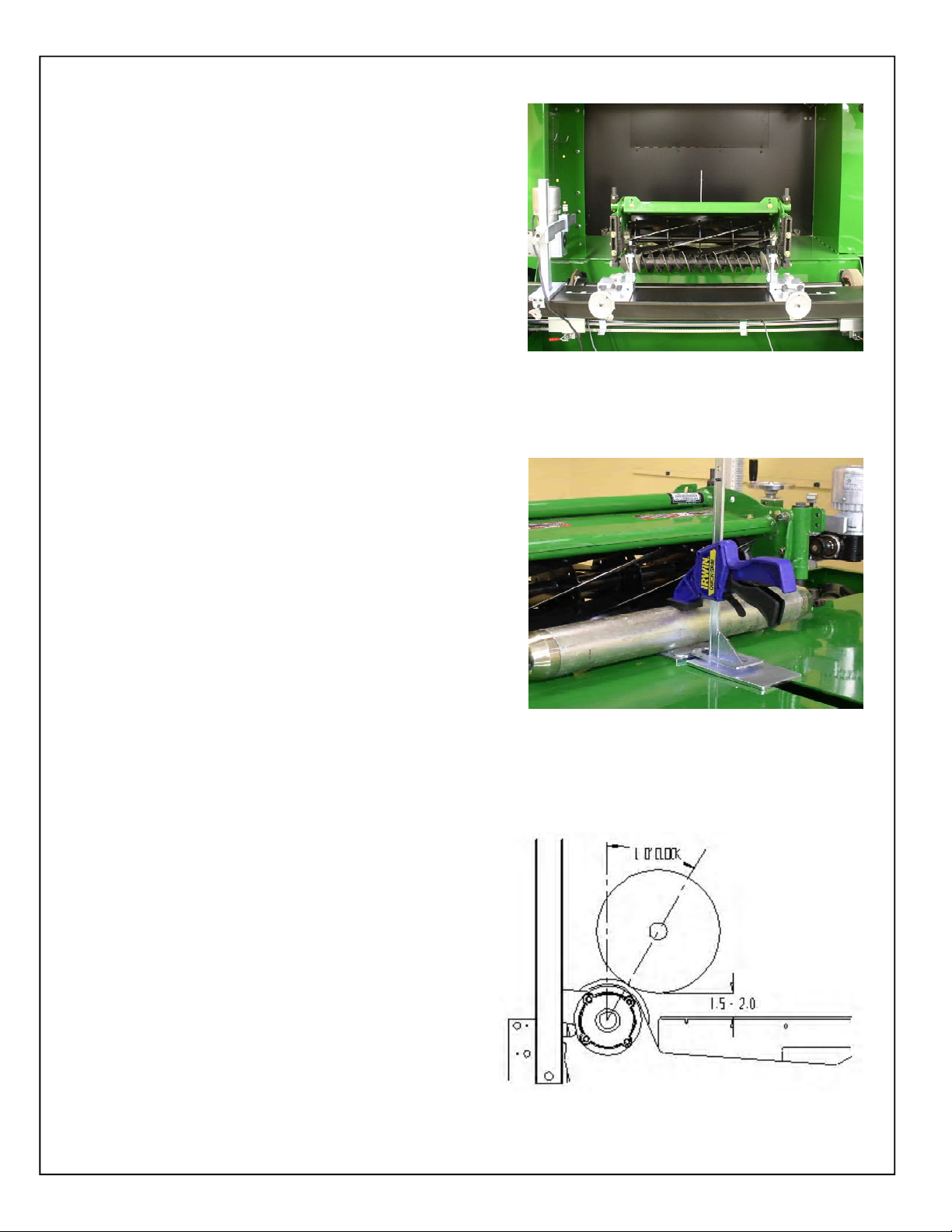
INSTA LL REEL
Move the r eel to the appr oxim ate position having the r ear
roller on the tabletop, and front roller on the front roller
Mounts.
MAKE SURE THE GRINDING WHEEL IS LOW
ENOUGH TO CLEAR THE REEL. YOU CAN
LOWER THE GRINDING WHEEL BY
TURNING BOTH HANDWHEELS
!
Position front r eel in the center of the machine. Move the
roll er m ounts as far o ut as poss ible to the e nds of the fro nt
roller. (See FIG 11). Us e the dec al s on the tool i ng bar to
aid in the positioning of the front tooling. Check for
clearance to the tooling, front rol l er and fram e w i th both
the spin and relief wheels. This will ensure that yo u will
not have to move the reel between the spin and relief
grinding. NOTE: On large reels it may be necessary to
offset the r eel s light ly fro m cente r t o allow the s pin driv e to
be mounted on the app ropriate s ide of the cuttin g unit.
COUNTERCLOCKWISE.
FIG. 11
Place the rear roller onto the rear roller clamp.
(See FIG 12).
If using the all- position brac kets, set the vertical height of
the clamps so that the bottom of the reel i s 1.5-2. 0 inches
[38-51mm] above the table. It is also recommended to
mount the support ar m with as l ittle extensi on from the all
position bracket as possible leaving just enough clearance
for mounting the reel in the “V” of the support arm.
Position the reel in and out by adjusting the front
handwheels. The reel should be positioned so that the
reel shaft is located at a 1 o’clock or 30° position to the
grinding wheel. See figure 13. If there are clearance
issues the reel can be moved forward or backward to
resolve this is sue. If y ou are gr indi ng a QA5 or QA7 r eel
use the decals located on the tool ing to quic kly l ocate the
reel in the optimal position. See FIG 2. After the reel is
positioned corr ectly lock dow n the front roller and tighten
the rear clamp. Make sure all knobs are tight before
grinding.
FIG. 12
30° angle or
!
FIRMLY TIGHTEN ALL LOCKING KNOBS
BEFORE GRINDING. ANY LOO SE KNOBS,
CLAMPS OR BEARINGS WILL ADVERSELY
AFFECT THE GRIND QUALITY.
FIG. 13
16
Page 17

OPERATING INSTRUCTIONS (Continued)
AL I GN TH E REEL
IMPORTANT: When measuring to the reel center shaft
always mak e sur e you are contacti ng an area free of dirt
and grass.
The di gital gauge hor izonta l extens ion bra cket i s ver tical ly
adjustable to allow the digital gauge to be positioned to
avoi d any reel fr ame mem ber . In ad ditio n, the mo unting of
the vertical slide to the horizontal weldment has three
positions . Rem oved the kno b on the si de to adju st the til t
of the vertical slide if necessary to avoid a reel frame
member. Se e FI G . 14.
Before aligning the cutting unit, loosen the horizontal
locki ng knobs on the too ling, to all ow the cutti ng unit to be
adjusted i n the hor izont al pl ane. See F IG. 14.
T o alig n the cut ting unit, m ove the digi tal gauge as sembly
as far as possible to the left side of the reel. Extend the
digita l gauge maki ng sur e the t ip of t he gaug e is c enter ed
on the reel center shaft. See FIG 15. With the gauge
pressed against the reel center shaft, set the gauge to
zero. R etract the gauge and move to the r ight si de of the
reel and measure to the center of the reel shaft. Do not
rotate the reel shaft ex cept for a mini mum amoun t if ther e
are clearance issues to the reel blades. With the gauge
against the center s haft, adjust the horizon tal handw heel
until the gauge reads zero. Repeat adjustments going
from one side to the opposite side until the alignment is
within .005" [.13 mm ].
GAUGE ANGLE
ADJUSTMENT
T-KNOB
FORWARD AND
BACKWARD
MOUNTI NG HOL ES
TOOLING BA R
POSITION KNOB
HORIZONTAL
LOCKING T-KNOB
GAUGE VERTI CAL ADJUST MENT T-KNOB
HORIZONTAL
ADJUSTMENT
HANDWHEEL
GAUGE
BASE
FIG. 14
CHECKING FOR TAPER
First, m easure the left si de of the reel as far to the left as
possible wi th the di gital ali gnment gauge, make sur e the
tip of the gauge is centered on the reel center shaft. Set
the gauge to zero, then measure to the edge of one blade.
Remember or write thi s number down. Mov e to opposite
side and do the same thi ng. Compar e the tw o numbers ;
the difference is the amount of taper in the radius of the
wheel.
NOTE: TO OBT A IN A CORRECT TA PER REA DING TO
BE USED WITH THE TAPER CHART LATER, THE
READING MUST BE TAKEN AS CLOSE TO THE
ENDS OF THE REEL AS POSSIBLE GIVING THE
MAXIMUM DISTANCE BETWEEN READINGS.
T o r emove the taper in the reel , the side of the reel that i s
larger will need to be infed heavier to remove this extra
material.
Remove the gau ge and st ore the di gital gauge on the pin
located on the front r ight si de of the machine. The ga uge
base can be placed ins ide the mac hine out of the way.
FIG. 15
FIG. 16
17
Page 18

OPERATING INSTRUCTIONS (Continued)
ALIGNMENT OF GRINDING SHAFT T O REEL
T o ali gn the grin ding s haft t o the reel bri ng the sh aft up so th at
the spin wheel is about ¼ inch [6 mm] from the reel blades.
Move the spin wheel to one side of the reel and raise the
grinding shaft until the wheel just touches the blade. Move
the wheel to the other side of the reel and bring the shaft up
until the wheel jus t touches . Recheck from s i de to si de and
make minor adjustments until the wheel touches the same
on both ends of the reel. The grind shaft is now aligned
verti cal ly to the r eels ou ter diam eter. Ze ro the ga uges loc ated
on the vertical adjustm ent housing. Check for high spots in
the reel by moving the wheel the length of the reel while
spinning the reel. If there are high spots lower the shaft equally
on both ends and zero out the gauges again.
FIG. 17
SETT ING T HE T RAVERSE L IMITS
Move the grinding wheel to the right until the wheel has
cleared the reel by approximately ¼ inch [6 mm] (if
clearance to the frame allows). Disengage both the relief
and Spin grinding assemblies from traverse belt. Turn the
Traverse speed potentiometer to zero and turn on the
Traverse Motor Switch. This will activate the proximity
sensors. Mov e the right T rav erse Tr avel Li mit s witch in until
the light on the proximity sensor illuminates. Move the wheel
to the opposite end, clearing the reel as mentioned above,
and set the left Traverse Travel Limit Switch. (Fig 17)
Engage the trave rse bel t and sl ow ly tu rn the Tr aver se S peed
up. Allow the wheel to traver se from end to end to verify the
switches stop and reverse the direction of the grinding wheel.
V erify t hat t he grindi ng wheel travel s fully of f the reel at each
end. Note: If the reel will hit the f rame , then adjust travel
sensors so the w heel does not contac t the fram e.
ATTACHING THE VARIABLE SPEED SPIN DRIVE
UNIT TO T HE REEL
IF THE REEL FRAME EXTENDS
BELOW THE REEL ITSELF, MAKE
SURE THE STOP IS SET SO THAT
THE GRINDING WHEEL DOES NOT
RUN INTO THE FRAME WHILE
!
GRINDING.
FIG. 18
The spin driv e unit attaches to the end of the reel shaft or a
drive system compo nent. Consult the cutti ng unit m anual for
proper spin drive placem ent and attachment. Determi ne which
side to mount the spin drive. This will generally be the same
drive system component used for backlapping. See FI G . 18.
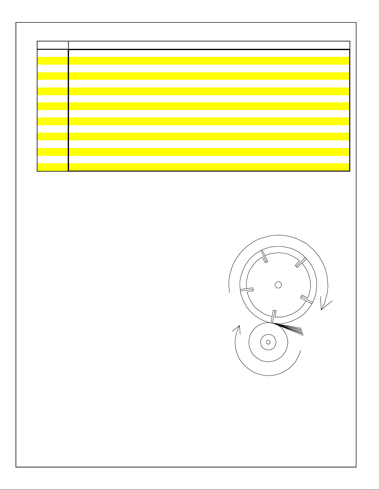
IMPORTANT: When spin grinding, the reel should turn in
the same directi on as the grindi ng wheel. See FI G . 19.
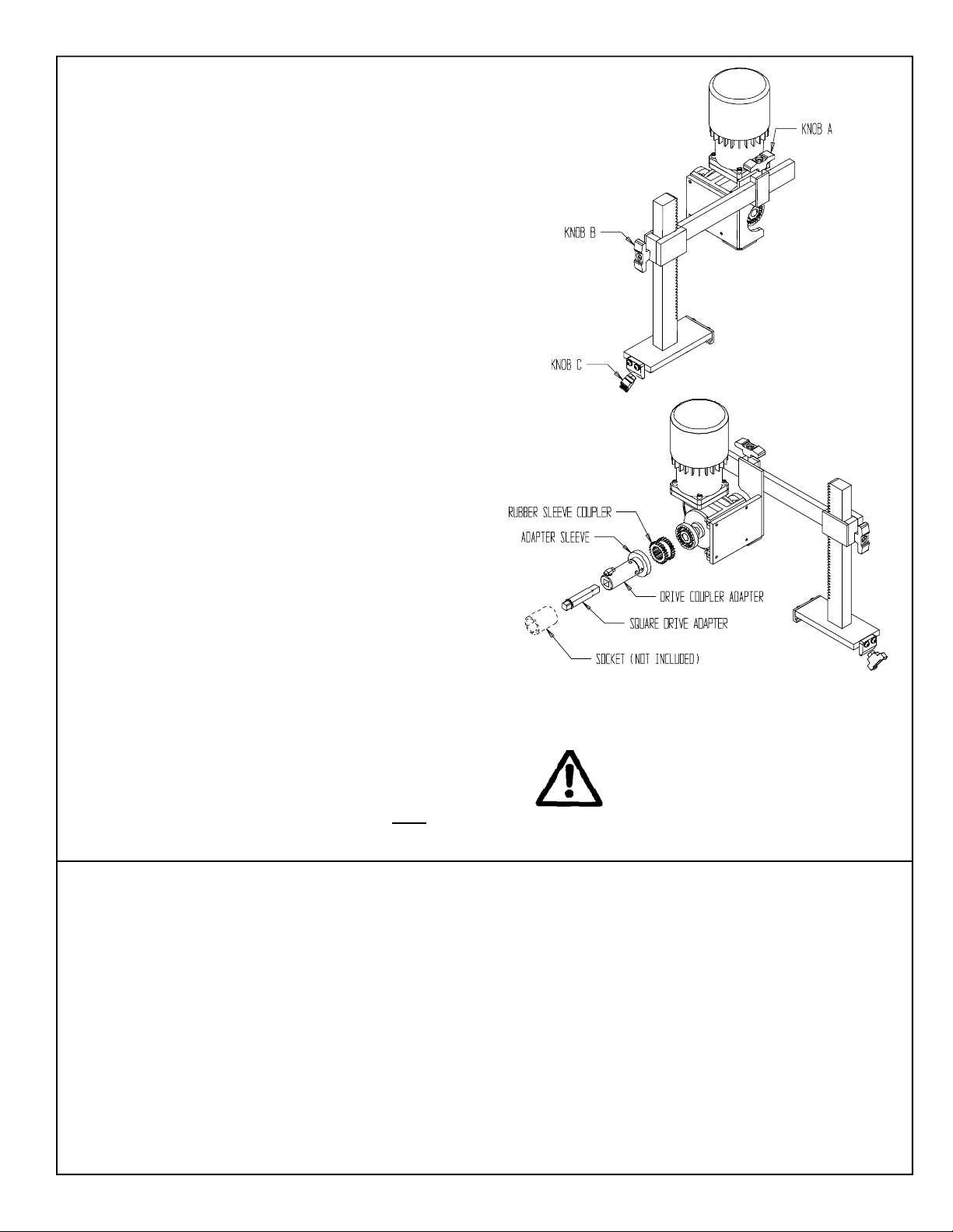
Befo re po sitio n ing th e sp in u nit let us f a miliariz e o urs elve s
with the availabl e adj ustments and coupler /dri ve assembl ies.
See FI G . 20.
18
FIG.19
Page 19
OPERATING INSTRUCTIONS (Continued)
Knob A—
Allows the spi n unit to be loosened and moved in and out.
Knob B-
Allows the spi n unit to be loosened and moved up and down.
Knob C –
Allow s t he spi n ass embly t o be loosen ed from the to oling b ar and
moved sid e-to-si de.
When positioning the spin unit it may be necessar y to complete
several of the above adjustm ents to proper ly al ign the spi n unit to
the reel .
THE COUPLER ASSEMBLY INCLUDES:
RUBBER SLEEVE COU PLER: This is placed in the
corresponding flange c oupler already mounted in the s pin
drive shaft. See FIG. 21.
DRIVE COUPLER ADAPTER ASSEMBLY: This is
mounted to the rubber coupler .
Note: If the Drive Coupler Adapter is removed, there is a
short square drive shaft attached to the Adapter Sleeve.
This can be used with a socket if there is li mited space.
AD APTER SLEEVE: Connects the rubber coupler to the
square dri ve adapter .
SQUA RE DRIVE A DAPTER: This is inser ted into t he drive
coupler adapter. The square drive adapter has
approximately 2" [51 mm] of movement. It will be
necessary to move this when attaching reel to spin drive
unit. This adapter shaft has a groove machined into it on
the opposite end of the snap ring. This groove is there to
advise that you have reached the maximum extension of
the square drive shaft. If you cannot connect the reel
without extending past this groove, then the spin unit must
be repositioned on the tooling bar (Knob C). A 1/2"
[12.7 mm] sq uare driv e socket or reel drive a dapter is u sed
to connect the square dr ive adapter to the reel.
NOTE: The 1/2" [12.7 mm] square drive socket or adapter
that is plac ed on the reel w hen spin grindi ng is NOT
with the grinder. See next page for details
included
FIG.20
FIG. 21
DO NOT EXTEND SQUARE
SHAFT PAST GROOVE, INSTEAD
REPOSITION SPIN UNIT.
The followi ng procedur es will make setting up the spin drive unit easier .
1.
Move spin dri ve unit cl ose to the reel. Ali gn the shaft on the spin drive wi th the nut on reel by completing the
necessary adjus tm ents disc uss ed above.
2.
Now sl ide the spin drive uni t appr oxim ately 7 " [18 cm ] from the ree l dri ve co upling poi nt and secu rely fasten to
the tooling bar tighte ning the l ocking knob. (Kn ob C)
3.
Place the proper 1/2 " [12.7 mm ] square dr ive soc ket or adapt er on the reel driv e nut and then ins ert the squar e
drive shaft into the socket. Place the adapter sleeve over the drive shaft and insert the dri ve coupler adapter
assembly into it. Final ly pl ace the rubber coupler onto the drive coupl er adapter. See FIG. 21.
4.
By holding the square drive shaft firmly into position with your left hand you will be able to move the oth e r
components to the right and inser t the rub ber coupler i nto the flange on the spin driv e unit. When this is done
tighten the T - Knob on the adapter sleeve to hol d all part s in plac e.
Finally r eadjust the spin dr ive unit if it i s not in alignm ent.
5.
NOTE: It i s not necess ar y to have perfect alignment but it must be cl os e enough so that the coupler remains
engaged and that excess tor que is not appli ed to the reel.
19
Page 20

OPERATING INSTRUCTIONS (Continued)
REEL DRIVE ADAPTERS
T
his grinder is equipped wi th an adapter that transfers the rotation from the spi n drive gear box coupling to a
1/2" male square. To operate the grinder you need an adapter from this 1/2" male squar e to the reel shaft.
These adapters are NOT
Most cutti ng units In recent y ears have a mal e or female spl ine on the end of the reel shaft that c onnects to
a hydraulic or elec tric motor shaft.
If you have a reel shaft that has an internal threaded end whi ch you can access, instal l a hex head bolt or
socket head screw of that thread size w ith a jam nut ver y tight so i t does not loos en whil e spin gr inding and
then drive with a 1/2" driv e socket for that hex or hex key size.
JOHN DEERE REELS
COUPLERS- T he external spline shafts use a female splined coupler between the reel shaft and the male
splined hydraul ic m otor shaft. The spli ne is either an 8,9 or 11 toothed spline. Our r ecomm endation is to
purchase the female s plined coupler from John Deer e and w eld it to a shor t 1/2" square socket extens ion.
Note: The 8 tooth spline adapter can be used with a Square Socket Dri ve Adapter [3/8" s quare male to 1/2"
square female] without w elding.
included w ith this grinder.
REEL DIA
REEL TYPE Recomendation
5 " G, M Has an 8-T, Extern a l shaft. U se co upler AET11038
7 " H Has an 11-T, External sha ft. Us e coupler TCA12581
(NOTE: THIS CAN ALSO BE DRIVEN WITH A 1.25 HEX SOCKET)
7 " 26H Has a 9-T, Extern al sh aft. U se co upler AET11310
(NOTE: THIS CAN ALSO BE DRIVEN WITH A 1.25 HEX SOCKET)
8 " ESP Has a M16 X 2, Externa l sha ft. Use nut A31869 and dr ive with
a 24mm Hex Socket.
5 " WB G M Use a 3/ 8"-24 UNF B olt, and d rive with a 9/ 16 Hex So cket
5" QA5 Has an 8-T, Internal Spline shaft. Use part AMT3022, to make
an adapter.
7" QA 7 Has an 11-T, Internal Spline shaft. Use a 1.25 Hex Socket or
make and a dapter from pa rt TCA18958.
TORO EQUIPMENT :
T oro uses a n 8 tooth female spline or a 9 tooth female spline on their reels. The 8 tooth female spline can be affectively
driven with a Square Socket Drive Adapter [3/8"square male to 1/2" square female]. The 9 tooth spline requires an
adapter . Our r ecommendation is to p urchas e ada pter Toro too l part nu mberTOR-4074 available from
K-Line Industries, Inc. 31 5 Garden Ave. Holland, MI 49424.
JACOBSEN EQUIPMENT :
Below is a list of drive systems based on the cutting units:
* 5" reel units can be driven from the non hydraulic motor end of the reel. Install a 3/8" bolt in the end of the reel shaft
with a jam nut very tight so it does not loosen while spinning. Use a 9/16" socket to drive. They can also be driven from
the hydraulic motor end by pressing a Square Socket Drive Adapter [3/8" square male to 1/2" square female] into the
splined reel coupling Jacobsen part number 337370 and use this pressed as sembly as the adapter.
* 7" reel units can be driven from either end. The reel unit has a coupler attached to the reel shaft a both ends. Purchase
Jacoben part number 4102440 Reel Motor Shaft and weld the hydraulic motor shaft form the kit to a 1/2" socket and use
this weldment as the adapter.
* Tri-King reel units can be driven on older pulley drive units with a 9/16" socket on the 3/8" bolt that holds the pulley. On
newer splined units, purchase the splined reel coupling Jacobsen part number 132002 and press a S quare Socket Drive
Adater [3/8" square male to 1/2"square female] into the splined reel coupling and use this assembly as the adapter.
20
Page 21

OPERATING INSTRUCTIONS (Continued)
RECOMEN DA TION FOR SPI N DRIVE RPM A ND
TRANSVERSE SPEED WHEN GRINDING
SPIN DRIVE RPM
SPIN DRIVE RPM IS VERY IMPORTANT IN
ACHIEVING A QUALITY GR IND. USE C ARE IN
ESTABLISHING THE SPIN DRIVE RPM, PER THE
INSTRUCTIONS BELO W.
Generally, the Spin Drive RPM will be be tween 180
RPM (45%) and 380 RPM (100%). The speed required
to spin a specific reel is dependant on reel diameter,
the number of reel blades, and reel hardness. For all
reels, there i s an opti m um Spin Speed where ther e i s
an AGGRESSIVE, yet smooth grind as you spin gri nd
the reel. Your objective is to spin grind the reel as
aggressi vely and as fast as pos sibl e w hile m aint aining
top quality .
It is r ecommen ded to star t grinding eac h reel at a S pin
Speed of 200 RPM (50%) and evaluate the RPM by
adjusting hi gher and lower to opt imiz e the S pin S peed
for that reel. If the Spin Speed is incorrectly set, you
can experience two problems, grinding wheel
dressing or grinding w heel resonance. Each of these
problems is explained below .
On some reels, especially small diameter high blade
count reels if the Spi n S peed RPM is s et too high, the
reel can act as a dr esser to the grinding w heel. T here
can develop what appears to be a very aggressive
grind (as if the infeed has self infed) and then a
sudden stop of grinding with no grinding wheel to reel
contact. If this occurs, your Spi n Speed was set too
high and you effectiv ely dressed y our g rinding w heel.
Some ree ls have a res onant R PM w here the reel goes
into harmonics with the grinding wheel and the
resonance vibrates the grinder and results in a very
bad grind. By changing the Spin S peed to a higher or
lower RPM you will move out of the resonant range.
After determini ng the best S pin S peed RPM for a reel,
note the RPM on the "Set-up Chart" in the "NOTES"
section. (Set-up chart is located at the back of th is
manu al) By no ting th e correct RPM, you will a void
evaluating the Spin S peed the next time y ou grind the
reel. Also note the spin drive position using the
position decals on the spin mounting and
documenting the position on the "Set-up Chart".
TRAVERSE DRIVE RPM
The T raver se Speed potentiom eter is adjust able from
approximately 5 feet per minute [1.5 meters per minute]
to 20 feet per minute (6 meters per minute). It is
recommended to grind between 15 and 20 feet per
minute (4 and 6 meters per mi nute).
Gri nding a t a slow er tr aver se spee d, 10 feet p er min ute
(3 meters per minute) as an example, will give a better
finish but will extend the gri nd cycle ti me. Grind finish
versus grind cycle time is controlled by the choice of
the operator .
COMPENSATING FOR TAPER.
To maintain the best quality of cut, the taper in a reel
must be removed returning the reel to a true cylinder.
T o re move the t aper that w as measur ed with the gauge
(as discussed previously in Checking For T aper Section)
first align the reel to the shaft by the touch m ethod (as
discussed previously). Then drop the side of the
grinding shaft that is hi gh (the sm all er side of the reel )
the amount suggested in the chart
[See char t on next page or Compensation for
Taper Chart located on the machine].
Example: For a r eel that is 22 i nches [56 c m ] long
with a measur ed t aper of .12" [3 m m ],
the adjuster on the smaller side of the reel
would be dropped to read-.546 [13.9 m m].
This will bring the grinding shaft parallel to the reel
center shaft. Z er o out the di gi tal g auges loc ated on the
vert ical adj ustme nt tower s and infeed both side equal ly
until the wheel just touches the large side of the reel.
Zero the gau ges again, you are now rea dy to grin d and
remove the taper. When grinding, the wheel will only
make contact with the larger side of the reel and will
gradually grind more as the larger areas are ground
away. The reverse button may be used to help speed
of this process . Gri nd until full c ontact is made acros s
the entire length of the reel, and the reel is sharp the
entire width of all blades .
AMOUNT OF
AMOUNT
OF TAPER
IN SHAFT
TAPE R IN REEL
21
Page 22
OPERATING INSTRUCTIONS (Continued)
TAPER A DJUSTMENT SETUP C HART
REEL WIDTH
16 18 20 22 24 26 28 30 32
0.005 0.033 0.029 0.025 0.023 0.021 0.019 0.017 0.016 0.015
0.010 0.066 0.058 0.051 0.045 0.041 0.038 0.035 0.032 0.030
0.015 0.100 0.086 0.076 0.068 0.062 0.056 0.052 0.048 0.045
0.020 0.133 0.115 0.102 0.091 0.082 0.075 0.069 0.064 0.060
0.025 0.166 0.144 0.127 0.114 0.103 0.094 0.086 0.080 0.075
0.030 0.199 0.173 0.153 0.136 0.123 0.113 0.104 0.096 0.089
0.035 0.233 0.202 0.178 0.159 0.144 0.132 0.121 0.112 0.104
0.040 0.266 0.231 0.203 0.182 0.165 0.150 0.138 0.128 0.119
0.045 0.299 0.259 0.229 0.205 0.185 0.169 0.156 0.144 0.134
0.050 0.332 0.288 0.254 0.227 0.206 0.188 0.173 0.160 0.149
0.060 0.399 0.346 0.305 0.273 0.247 0.225 0.207 0.192 0.179
MEASURED T APER
SPIN GRINDING
After the reel has been aligned and the taper has been
adjusted for , you ar e now ready to spin grind the r eel. Cl ose
the front and r ear guar d doors. (The g rinding w heel and spin
motors will not work unle ss th e doors are closed.) Position
the spin/relief selector switch to the spin position. Tu rn on
the Grinding M otor and the S pi n Dri ve M otor swi tch. Set the
spin speed at approximately 200 rpm (Refer to Spin Drive
RPM on per vious page) . M ake s ure spin r otation i s the same
as the grinding wheel – clockwise (CW) looking from right
end. See FI G 22.
0.070 0.465 0.403 0.356 0.318 0.288 0.263 0.242 0.224 0.209
0.080 0.532 0.461 0.407 0.364 0.329 0.301 0.277 0.256 0.238
0.090 0.598 0.519 0.458 0.409 0.370 0.338 0.311 0.288 0.268
0.100 0.665 0.576 0.508 0.455 0.412 0.376 0.346 0.320 0.298
0.120 0.798 0.692 0.610 0.546 0.494 0.451 0.415 0.384 0.358
Small side of reel downward adjustment.
IM PORTANT: When the reel turns i n the sam e rot ation as
the grinding wheel , the point of contact where they meet is
in opposit e direc tions.
Tur n on the tr averse dr ive m otor sw itch and turn the speed
dial up to approxi matel y 15- 20.
IM PORTANT: If the gri nd st arts get ting heav ier , adjust the
grindi ng head down u ntil yo u can tr avel th e full length of the
reel w ithout heav y grindin g.
When grinding, infeed the wheel approximately .005” [.13 mm]
at a time. Allow the grinding wheel to travel back and forth
across the reel 2 to 3 times before infeeding. The spin
grinding is completed when full contact is made across the
entire le ngth of the reel, the entire width of all bl ades and the
reel is s harp. The l ast pas ses shoul d be a norm al .005 [.13
mm] infeed gri nd at a slow trav erse speed (appr ox. 8 feet per
minute [2.5 meters per minute] or slo wer). Aft er the l ast pass
turn the grin der off.
(Note: Due to the positioning of the reel to the 1 o’ clock posi tion,
infeeding the wheel .015 inches [.38 mm] will remove .010
inches of material. )
22
FIG.22
Page 23

OPERATING INSTRUCTIONS (Continued)
RELIEF GRIND
T o change over to the relief grind, disengage the spin grinding wheel
hub assembly and par k i t as far to the ri ght as possibl e. Bring the
relief hub assembly over to the reel for relief grinding. This will
require repos itioning the tr avel pr oximity switch br ackets.
Note: As the reel diameter get s sm aller and the num ber of blades
increases the relief grinding wheel diameter works better when
smaller. For exampl e a 5" [127 mm] diameter greensm ower r eels
with 1 1 bl ades ach ieve a greater rel ief angle wi th a sma ller gr inding
wheel.
REEL SPIRAL
Check to see if your mow ing unit is nor mal or reverse hel ix.
NOTE: As you look into the gui de finger on TH E NEXT PAGE, IT
SHOWS TH E NORM AL REEL HELIX. As you l ook into the guide
finger on the FOLLOW PAGE, IT SHOWS THE REVERSE
REEL HELIX. The high po int of the reli ef finger is on th e right h and
side of the grinding wheel .
Most m owing units ar e nor mal hel ix.
THE HIGH POINT OF THE RELIEF FINGER MUST
ALWAYS BE AT THE CORNER OF THE GRINDING WHEEL
THAT IS MAKING CONTACT WITH THE REEL. ON THIS
GRINDER THAT IS ALWAYS THE RIGHT HAND SIDE OF
!
WHEEL DRESSING
If the grinding wheel becomes loaded with material it may be
necessary to dress the wheel. The RG5500 is supplied with a
diamond dresser. To use, place the dresser on the spin drive
horizontal arm in the area where the wheel is to be dressed.
Adjust the dresser to the appropriate position and angle. Raise
the grinding wheel so it i s nearly touching the dress er .
For dressing the spin grinding wheel, put the dresser in the straight
position. Close the door s and infeed the spin grinding wheel into
the dresser and then move the gr inding wheel side to side agai nst
the dresser which will dress the full face of the wheel.
THE GRINDING WHEEL.
FIG.23
T ypic ally onl y infeed .002 " [.05 mm] per pas s. Infeeding too heavy
can dam age the dresse r or the w heel. Contin ue dres sing unti l the
wheel looks new or the proper shape is achieved.
For dressi ng the rel ief w heel, put the dr esser at the corr ect angle
for normal helix reel or reverse helix reel. Close the doors and
infeed the relief grinding wheel into the dresser. Do NOT move
the grinding wheel from s ide to side.
23
Page 24

OPERATING INSTRUCTIONS (Continued)
Matching Angle
Actual Grindi ng Wheel
Contac t Point
Prefered Dres sing
New S traight Wheel
Right Side of Wheel
Must Contact First
NORMAL HELIX
24
For a N ORMA L HELI X re el, the gr inding w heel
should wear to match the angle of the reel
blade.
NOTE: The square faced grinding wheel as
purchased from the factory can be used for
normal helix reels and will wear to match the
reel blade helix.
Normal helix reels are also refered to as Left
Hand Side Cutting First (Looking from front -
grass entry position.) or Right Throw reels
(Throws grass to the right of operator
position.)
Page 25

OPERATING INSTRUCTIONS (Continued)
Matching Angle
Actual Grinding Wheel
Contac t Point
Prefered Dressi ng
Right Sid e of Wheel
Must Contact First
For a REVERSE HELIX reel, the grinding wheel should
be dressed to match the angle of the reel blade. It is
recomm ended that a slightly larger angle is dressed on
the wheel so the right side of the wheel is contacting the
blade prior to the left side as shown. The grinding w heel
will then wear to a match.
REVERSE HELIX
25
If you do not dress the grinding wheel so the right side
contacts first you may not relief grind part of the last 3/8"
[10 mm] of the blade.
NOTE: A wheel that has been worn to match a norm al hel ix
can generally be rem oved and rev ersed to grinder rever se
helix. reels.
Reverse helix ree ls are also refered to as Right Side
Cutting First reels (Looking from the front - grass entry
side) or Left Throw reels (Throws grass to the left of the
operat or position .)
Page 26

OPERA TING INSTRUCTIONS (Continued)
RELIE F GRINDING CONTINUED
Reset the Traverse Limit Pr oxi m i ty Sw i tc h so the
grinding wheel clears the reel at both ends by
approximately 1/16" [1.5 mm].
Set Grind Selector s witch to variable tor que relief.
(IMPORTANT: The Spin Drive Rotation switch must be
in the OFF position when changing the Grind Selector
switch.) Set the Spin Drive Rotation switch to rotate the
reel into the stop finger, counterclockwise (CCW) when
look ing at the r ight s ide . NOTE: Relie f tor que r eel rotati on
is al ways opposi te spin r otati on. DO NOT T URN ON T HE
SPIN MOTOR SWITCH.
With the traverse in the home
position (right side traverse
proximity sensor lit), infeed the grinding relief wheel up
while manually rotating the reel until the index finger
touches t he blade.
Tur n the travers e speed potentiometer to zero, then turn
the traver se drive motor on. With the bel t drive dis engaged,
manually move the Relief Grinding Assembly to the left
until the r eel bl ade is on the fixed r elief finger.
INDEX FINGER
STOP POSITION
KNOB
WHEEL DIA METER
ADJUSTMENT
HANDLE
RELIEF ANGLE
ADJUSTMENT
HANDLE
FIXED FINGER
INDEX STOP
PIN
MOVABLE
INDEXI NG
FINGER
At this point, i f necessary , you can adj ust the rel ief angle
by adjusting the relief finger position. To make this
adjustment loosen the Relief Angle Adjustment handle.
See FIG 24. Rotating the finger system down will increase
the relief angle and rotating the finger system up will decrea se the reli ef angle. Adju sting the r elief angl e or index
finger stop position is easiest with the relief head at the
left side o f the reel.
Once you have the Grinding Head pos itioned with a reel
blade r esti ng on the F ixed R eli ef Fin ger high point , adju st
the indexing finger stop. There should be about 1/32"
[.8mm] to 1/16" [1.5m m ] free pl ay of the I ndex F i nger to
the back of the blade. The Inde x Finge r i s spri ng loaded
to the up posi tion or again st the back o f the r eel bl ade. To
check free play, push down on the Index Finger.
See FIG 24. If there is no free play of the Index Finger you
want to rotate the Adj ust able Index F inger S top Posi tion
Knob counter clockw i se. If there is m or e than 1/16" [1.5
mm] free play you want to rotate the Index Finger Stop
Position Knob clockwise.
IMPORTANT: The Index Finger position must be set to
stop the r eel blad e and al low tr aversi ng to the le ft witho ut
the blade hitti ng the side of the r elief finger . Thi s position
must also allow approxi mately 1/32" [.8 m m] free play of
the index finger when the blade is resting on the high point
of the relief finge r . See FIG . 24.
Infeed the grinding wheel up until there is minimal
clearance between the reel blade and the grinding wheel.
INDEX FINGER
FORWARD STOP
POSITION
SETSCREW
FIG 24.
FIG 25.
26
Page 27

OPERA TING INSTRUCTIONS (Continued)
RELIE F GRINDING CONTINUED
Close the front and rear doors.
Tur n the Spin Motor Switch on.
NOTE: The spin drive will apply torque load against
the finger s.
Set the Rel ief Torque Potentiom eter at appr oximate ly
15. IMPORTANT: Free turning reels may need a lower
value than 15 and sti ff reels or r eels with a drive tr ain
may need a higher torque than 15.
Engage the traverse belt and tr av er se al l the w ay to
the left watching for proper clearance between the
grinding wheel and the blade. Check for proper
clearance between the index finger (after releasing
from bl ade at far left posi tion) a nd the front side of the
blade on the return trip to the home
clearance to the reel blade support spiders. If
necessary the forward stop can be adjusted.
See FI G 25.
position. Also ver ify
Stop the traverse in home
proper blade index. The traverse drive control is
factory set with a two second dwell time before it
reverses the carri age tr avel . This i s to al l ow tim e for
the reel to rotate and the index finger to catch the next
blade. If necessary the dwell time can be adjusted
(refer to Control Board Potentiometer Adjustments
section in the Ass embly and Serv ice M anual).
Tur n on the Spin Drive Motor (should already be on)
and the Grinding Wheel Motor s witc h.
Turn the traverse speed potentiometer to proper
grind ing sp eed. Sl owly infe ed the grin ding w heel until
you are able to grind the full length of the reel evenly. A
typical infeed is b etween .010" to .020" [.25-.50 mm].
Be sure you have ground all the blades before
infeeding further.
NOT E : Traverse speed should be set to
approximately 15 fpm. If you are removing a small
amount of stock on initial infeeds, faster traverse
speeds are suggested. If you are removing a large
amount of stock on later infeeds, slower traverse
speed may be required.
position and check for a
After the relief grind is complete remove turn all
switches to off (it i s als o good practic e to push i n the
E-stop button) then remove cutting unit from the
machine. Use caution as the reel blades will be sharp.
27
Page 28

REEL SETUP CHART
NOTES
E
S
G
R
N
D
E
I
E
T
V
A
E
T
E
P
R
T
S
S
SPIN
TORQUE
SETTING
frame, reel dia., height of cut, roller position, etc.
Note: These dimensions will vary due to reel position in
SPIN
SPEED
SETTING
E
V
N
I
R
O
D
TI
I
N
S
I
P
Use these values as a guide only.
O
S
P
SPIN DRIVE
MOUNTING
SIDE R OR L
TOOLING
DISTANCE
APART
FRONT
TOOLING
MOUNT
POSITION
REEL SETUP CHART
FRONT
TOOLING
MOUNT
TYPE
REEL MAKE,
MODEL &
HEIG HT OF
CUT
28
Page 29

THIS PAGE LEFT INTEN TI ONALLY BLANK FOR NOTE TAKING PORPOSES.
29
Page 30

30
Page 31

ASSEMBLY
REEL MOWER GRINDER
RG5500
AND
SERVICE MANUAL
SPIN / RELIEF
(REV. 6/20/ 201 1)
1
Page 32

DEALER PREPARATION/INSTALLATION CHECK LIST
IS LOCATED IN THE OPERATOR'S MANUAL
SEE OPERA T OR'S M ANUAL F OR INSTALL TION CHEC KLIST
It is the r esponsibility of the dealer to com plete the procedures li sted in the Operators Manual then
review this checklist wi th the customer upon the delivery or the sale of this equipment.The ins tallation
trainin g goes over the basic op erational functi ons of the equipm ent. To ensure adequate train ing, we
require that the following i tems are r eviewed by your John D eere Dealer . Pleas e check off to ensure
that you under stand the follow ing items before the instal lation tr aining i s com plete:
Safety
IMPORT ANT SA FETY MESSA GE FOR OWNERS/OPERAT ORS OF REEL GRINDERS
Safety is a primary concern in the design,
manufacture, sale, and use of reel grinders. As
a manufa cturer of reel grinders, we w ant to confirm
to you, our customers, our concern for safety . We also
want to remind you about the simple, basic, and
common sen se rules of safety when using a reel
grinder. Failure to follow these rules can result in
severe injury or death to o perator s or bys tander s.
It is essential that everyone involved in the assembly ,
operation, transport, mainte nance, and storage of this
equipment be aware, concerned, prudent, and
properly trained in safety. Always use proper
shielding as specified by the manufacturer.
Our current production machines include, as
standard equipment, guards or shields for the
grinding wheel, safety signs and an operator's
manu al. Never by pass or opera te the m achine with
any of the guards or the saf ety devices rem oved.
Read and fully understand all the safety
practices discussed on pages 4 and 5 of this
manual. All safety rules must be understood
and followed by anyone who works with reel
grinders.
Before operating a reel grinder, an operator must
read and understand all of the information in the
operator’s m anual and in the saf ety signs atta ched
to the product. A person who has not read or
understood the ope rator’s man ual and safety s igns
is not qualified to operate the unit. Accidents occur
often on machines that are used by someone w ho
has not read the operator’s manual and is not
familiar with the equipment. If you do not have an
operator’s manual or the current production safety
signs, contact the manufacturer or your dealer
immediately.
Reel grinders are designed for one-m an operation.
Never operate the grinder with anyone near, or in
cont act wit h, any part of the grinder . B e sure no one
else, including bystanders, are near you w hen you
operat e this product.
Following these simple, basic safety rules, as well
as others identified in the owner’s manual and in the
product safety signs, will help minimize the
possibility of accidents and increase your
productivity in usi ng this product. Be careful and
make sure that everyone who operates the grinder
knows and understands that this is a very pow erful
piece of m achinery , and if used im properly, serious
injury or death may result. The final responsibility for
safety re sts with the operator of this mach ine.
2
Page 33

TO THE DEALER:
Assembly and pr oper inst allation of this pr oduct is the responsi bility of the John Deere dealer . R ead manual
instructi ons and s afety rules. M ake sur e all i tems on the Pr epar ation Chec k List in the Oper ator’s M anual are
complet ed before releasi ng equi pment to the owner.
TO THE OWNER:
Read the Oper ator's M anual before operati ng your Frontier equipment. Keep this and al l manuals handy for
ready reference. R equire all operator s to read the O perator's M anual carefull y and beco me acquainted with
all adjust ments and operating procedu res before at tempting to oper ate the equi pment. Repl acement
manuals can be obt ained from your selling deal er .
The equipmen t you h ave purc hased has been careful ly engineer ed and m anufacture d to provi de
dependable and satisfactor y use. Lik e all mechan ical pr oducts, it w ill require c leaning and upk eep. Lubricate
the unit as specified. Please obs erve all s afety information in the Oper ator's M anual and safety decals on
the equi pmen t.
For servi ce, your authorized John Deer e dealer has trained mechani cs, genuine Frontier servic e parts, and
the necessary tools and equipment to handle all of your ser vice needs.
Use only genuine Frontier servic e parts.
3
Page 34

SA FETY I NSTRUC TIONS
Safety Awareness Symbols are inserted
into this manual to alert you to possible
Safety Hazards. Whenever you see these
symbols, follow their instructions.
!
The Warning Symbol identifies
special instructions or procedures
which, if not correctly followed, could
result in personal injury .
1. KEEP GUARDS IN PLACE and in working
order.
2. REMOVE WRENCHES AND OTHER
TOOLS.
3. KEEP WOR K AREA CLEAN.
4. DON'T USE IN DANGEROUS ENVIRONMENT.
Don't use Grinder in damp or wet locations.
Machine is for i ndoor use only . Keep work area
well lit.
5. KEEP A LL VISITORS AWAY . All visitors
should be kept a safe dis tance from wor k area.
6. MAKE WORK AREA CHILD-PROOF with
padlocks or master switches.
The Caution Sy mbol id entifi es spe cial
instructions or procedures which, if not
strictly observed, could result in damage to
or destruction of equipment.
12. DON'T OVERREACH. Keep proper footing and
balance at all times .
13.MAINTAIN GRINDER WITH CARE . Follow
instructi ons in Ser vice M anual for lubric ation and
prev entive m aintena nce.
14.DISCONNECT POWER BEFORE SERVICING,
or when changi ng the g rindi ng wheel.
15.REDUCE T HE RISK OF UNINTENTIONAL
STARTING. Make sure all switches are OFF
before plugg ing in the grinder .
16.USE RECOMMENDED ACCESSO RIES.
Consult the manual for recom mended
accessories. Using improper accessories may
cause risk of personal injury .
7. DON'T FORCE THE GRINDER. It will do the job
better and safer if used as speci fied in this
manual.
8. USE THE RIGHT TOOL. Don't force the gri nder
or an attachment to do a j ob for w hich it was not
designed.
9. WEA R PROPER APPA R EL. Wear no loose
clothing, gloves, neckti es, or j ewelr y which m ay
get caught in moving parts. Nons lip footwear is
recommended. Wear protective hair cover ing to
contai n long ha ir .
10. ALW AYS USE SAFETY GLASSES.
11. SECURE YOUR WORK. Make certain that the
cutting unit is securel y fastened with the clam ps
provided before operating.
17.CHECK DAMAGED PARTS. A guard or other
part that is damaged or will not perform its
intended function shou ld b e proper ly r epaired or
replaced.
18.KNOW YOUR EQUIPMENT. Read this manual
carefully . Lear n its applicati on and limit ations as
well as spec ific potenti al hazar ds.
19.KEEP ALL SAFETY DECALS CLEAN AND
LEGIBLE. If safety decals become damaged or
illegible for any reason, replace immediately .
Refer to replacement parts illustrations in Service
Manual for the proper location and part num bers
of safety decals.
20.DO NOT OPERATE THE GRINDER WHEN
UNDER THE INFLUENCE OF DRUGS,
ALCOHOL, OR MEDICAT ION.
4
Page 35

SA FETY I NSTRUC TIONS
IMPROPER USE OF GRINDING WHEEL MA Y CAUSE
BREAKAGE AN D SERIOUS INJURY .
!
Grindi ng is a safe opera tion i f the few bas ic r ules list ed below ar e follow ed. T hese rul es ar e based on mater ial
contained in the ANSI B7.1 Safety Code for "Use, Care and Protection of Abras ive Wheels". For your safety ,
we suggest you benefit from the experi ence of others and follow these rul es.
DO
1. DO always HANDLE AND STO RE
wheels in a careful manner.
2. DO VISUALLY INSPECT all wheels before
mounting for p ossible dam age.
3. DO CHECK MACHINE SPEED against the
established max imum safe operati ng speed
marked on w heel.
4. DO CHECK MOUNTING FLANGES for equal
and correct di ameter.
5. DO USE MOUNTING BLOTTERS when
supplied with wheels.
6. DO be sure WORK REST is properly
adjusted.
7. DO always USE A SAFETY GUARD C OVER I NG
at least one- half of the gr inding wh eel.
DON'T
1. DON'T use a whee that is cracked, HAS BEEN
DROPPED, or one that i s damaged.
2. DON'T FORCE a wheel onto the machine OR
ALTER the si ze of the m ounti ng hole- -if w heel w on't
fit the machine, get one that will.
3. DON'T ever EXCEED MAXIMUM OPERATING
SPEED established for the wheel.
4. DON'T use mounting flanges on whic h the bear ing
surfaces ARE NOT CLEAN, FLAT AND FREE OF
BURRS.
5. DO N' T TI GH TE N t he m ounti ng nut EXCESSIVELY.
6. DON'T grind on the SIDE OF THE WHEEL (see
Safety Code B7.2 for excepti on).
7. DON'T start the mac hine until the WH EEL GU A RD
IS IN P LACE.
8. DO allow NEWLY MOUNTED WHEELS to run at
operating speed, with guar d in pl ace, for at least
one mi nute be fore gri nding.
9. DO always WEAR SAFETY GLASSES or some
type of eye p rotec tion when g rindi ng.
A VOID INHALATION OF DU ST gener ated by gri nding and cutting oper ations. Exp osure
to dust may cause respiratory ailments. Use approved NIOSH or MSHA respirators, safety
glass es or face shiel ds, and pr otecti ve clo thing . Prov ide a dequate venti lat ion to eli mina te
dust, or to maintain dust level below the Threshold Limit Value for nuisance dust as
classified by OSHA.
8. DON'T JAM wor k into the wheel.
9. DON'T STAND DIRECTLY IN FRONT of a
grinding wheel whenever a grinder is started.
10. DON'T FORCE GRINDING so that motor slows
noticeably or w ork gets hot.
5
Page 36

TABLE OF CONTENTS
This machine is intended for grinding the reel of reel type mower units ONLY.
Any use other than this m ay cause personal injury and voi d the warranty.
To assure the quality and safety of your machine and to maintain the warranty,
you MUST use original equipment manufactur's replacement parts and have
any repair work done by a qualified professional.
ALL operators of this equi pment mus t be thoroughly trained BEFORE operating
the equipment.
Do not use compressed air to clean grinding dust from the machine. This dust
can cause personal injury as well as damage to the grinder. Machine is for
indoor use only. Do not use a power washer to clean the machine.
Low Voltage Relay
The gri nder is equipped wi th a high- low vol tage rel ay
which is factor y preset at 100-140 V AC. If the power
supply l ine d oes not deli ver 100- 140 V A C power under
load, the relay will open and trip out the star ter . If this
occurs, your pow er suppl y l i ne i s i nc or r ect and m us t be
correct ed before proceedi ng further with the gr inder .
TABLE OF CONTENTS
Safety Instructi ons ................................................................................................................. Page 2- 6
Dail y M aint enance.................................................................................................................. Page 6
Service Data.......................................................................................................................... Page 7
Assembly Instructions............................................................................................................ Page 8- 12
Maintenance............................................................ .............................................................. Page 13-19
Adjustments........................................................................................................................... Page 20 -25
Electri cal Troubleshooting...................................................................................................... Page 26-41
Mecha nical Tr oubleshooting .................................................................................................. Page 42-43
Exploded Views and parts Lis ts ............................................................................................. Page 44-71
Wiring Diagram & Schematic ................................................................................................ Page 72-74
DAILY MAINTENANCE BY THE OPERATOR
On a daily basis, clean the m achine by w iping it off.
On a daily basis, remove all grinding grit from the grinding shaft, traverse shafts, and tooling
bar area.
On a daily basis, inspect the mach ine for loose fasten ers or compon ents.
Contact you r comp any's Maint enance Depar tment if dam aged or d efective parts ar e found.
DO NOT U SE C OMPRESSED A IR TO CLEAN
GRINDING DUST FROM GRINDER
6
Page 37

SERVICE DATA
SKILL AND TRAINING REQUIRED FOR SERVICING
This Servi ce M anual is des igned for techni cians who have the nec essary m echanical and electr ical
knowledge and s kills to reliably test and repair the RG5500 S pin/Rel ief Grinder. For those wi thout this
background, s ervice can be arra nged through y our loc al dealer .
This sectio n presum es that y ou are alr eady fam ili ar with the norm al operat ion of the gr inder. If no t, you shou ld
read t he operator s manual , or do the servi cing in conj uncti on wi th som eone w ho is familiar with its operation.
Persons without the necessar y knowledge and skills should not r emove any panels, shiel ds or attempt any
internal tr oubleshootin g, adjustments , or par ts replac ement.
If you have questions not answ ered in this manual, please cont act your deal er .
TORQUE REQUIREMENTS
Throughout this manual we refer to torque
requi rement s as "fir mly ti ghten" o r the li ke. For m ore
specific torque values, r efer to the information
below.
Bolts Going Into a Nut, or Into a Thread Hole in
Steel.
Refer to the table at the right.
Bolts G oing Into a Thread Hole In Aluminum
Use the Grade 2 values in the table at the right.
Socket-H ead Screw s Going Into a N u t or St eel
Use the Grade 8 values in the table at the right.
Machi n e Screws
No. 6 screws: 11 i n.- lbs ( 0.125kg - m )
No. 8 screws: 20 in. - lbs ( 0.23 kg - m)
No. 10 screws: 32 i n. - l bs ( 0.37 kg - m )
GRADE 2 GRADE 5 GRADE 8
SMOOTH 3 MARKS 6 MARKS
HEAD on HEAD on HEAD
1/4 In. 6 ft-lbs 9 ft-lbs 13 ft-lbs
thread (0.8 kg-m) (1.25 kg-m) (1.8 kg-m)
5/16 In. 11 ft-lbs 18 ft-lbs 28 ft-lbs
thread (1.5 kg-m) (2.5 kg-m) (3.9 kg-m)
3/8 In. 19 ft-lbs 31 ft-lbs 46 ft-lbs
thread (2.6 kg-m) (4.3 kg-m) (6.4 kg-m)
7/16 In. 30 ft-lbs 50 ft-lbs 75 ft-lbs
thr ead (4.1 kg-m) (6.9 kg-m) ( 10.4 kg-m)
1/2 In. 45 ft-lbs 75 ft-lbs 115 ft-lbs
thread (6.2 kg-m) (10.4 kg-m) (15.9 kg-m)
7
Page 38

A SSEMBLY INST RUCTIONS
Remove the sides , front, and back of the cr ate.
Remove the plasti c bag, shrink wrap and bubbl e
wrap. Remove the metal cl ips that secure the
grinder to the crate bas e. With a fork lift, raise the
grinder from the wood base and set it in its final
positi on. See FI G. 1 and 2.
THE UNIT WEIGHS
1200 LBS. [544 kg].
TO LIFT, USE POWER
EQUIPMENT.
Remove shipping straps and window protective
sheets.
R36"
[914cm]
83" [211cm]
OPTIONAL BOOM
71"
[181cm]
41" [104cm]
OPTIONAL
PLA TFORM
LIFT SYS.
45"
[11 5cm]
POSITION BASE
The RG5500 Spin/Relief Grinder will require an operating area of about 119" W x 127" D x 90" H
(302 cm x 323cm x 229 cm ). The m achine oper ator will operate the unit from the front of the m achine.
Position the base to allow suffic ient operating room i n front and to the rear of the machine. See FIG . 1
and 2.
The base should be placed on a rel atively lev el concrete floor , with am ple ceili ng height to allow for the
installati on of the unit. D o not pl ac e the uni t acr os s tw o conc r ete sl ab seam s or acr os s a large crack.
71"
[181cm]
83"
[21 1cm]
Optional
Boom Kit
88
[224cm]
FIG. 1
41" [104cm]
FIG. 23
OPTIONAL
PLATFORM LIFT
45"
[11 5cm]
70"
[178cm]
FIG. 2
8
Page 39

A SSEMBLY INST RUCTIONS (Continued)
Remove the carton and remove the contents from the carton
onto a workbench. The carton i ncludes:
Alignment Gage
Mult i posit ion Brac kets
Drive C oupler
Product Packet Assem bly
(Operators & Ser vic e M anuals)
Diamond Dresser
Raised Rear
Support
Sp anner Wrench
9
Page 40

A SSEMBLY INST RUCTIONS (Continued)
LEVEL BASE
Place a level on the top of the table and check the
unit for level s ide to side. Adjust the lev eling feet as
necessary until the m achine i s level .
See FIG. 3 and 4.
Place a level across the table from front to rear.
Adjust the leveling feet as n ecessary until the
machine is level . See FIG. 3 and 5.
When both front to back and side to side leveling
procedures have been completed, thread the hex
jam nuts up against the nut that is welded to the
bottom of the machine. Be careful not to move the
leveling feet during when tightening the jam nut. See
FIG. 3. Make certain that all four leveling feet are
firmly cont acting the floor.
Recheck that the machine is level after locking the
four feet i nto posi tion.
LOOSEN JAM NUT TO
ADJUST FOOT
LEVELING FEET LOCATED
AT CORNERS OF MAHCINE
FIG . 3
10
FIG . 4
FIG . 5
Page 41

A SSEMBLY INST RUCTIONS (Continued)
IMPORTANT GROUNDING INSTRUCTIONS
In case of a malfunction or br eakdown, gr ounding reduces the risk of electr ical shock by providing a path
of least resistance for electr ical curr ent.
This Gri nder has an elec tric al cor d with an equi pment grounding conductor and a groundi ng plug. The
plug must be plugged into a matchi ng outlet that is proper ly instal led and grounded ac cordi ng to all local
or other appropriate el ectrical codes and ordinances.
Before plugging in the Grinder , m ake sure it will be connected to a supply circuit pr otected by a properly
sized cir cuit breaker or fuse. SEE SER IAL N UM BER PLATE FOR FULL LOAD AM P RATING OF Y OUR
MACHINE.
Never modify the plug prov ided wi th the machine- -if it w on't fit the outlet, have a proper outlet and cir cuit
installed by a qual ified elec tric ian.
ALWAYS PROVIDE A PROPER ELECTRICAL GROUND FOR YOUR MACHINE.
AN IMPROPER CONNECTION CAN CAUSE A DANGEROUS ELECTRICAL
SHOCK. IF YOU ARE UNSURE OF THE PROPER ELECTRICAL GROUNDING
PROCEDURE, CONTACT A QUALIFIED ELECTRICIAN.
11
Page 42

A SSEMBL Y INSTRUCT IONS (Continued)
APPLY POWER
BEFORE YOU APPLY POWE R TO THE G RINDER,
REFER TO THE "IMPORTANT GROUNDING
INSTRUCTIONS" ON PREVIOUS PAGE.
Plug the control box power c ord into a standard 115V AC 20-am p
grounded recept acl e. See FI G. 6.
IT IS RECOMMENDED THAT THIS SPIN/RELIEF
GRINDER HAS ITS OWN PERMANENT POWER
CONNECTION FROM THE POWER DISTRIBUTION
PANEL, W IT H NO O T HE R MAJO R P O WE R D RAW
EQUIPMENT ON THE SAME LINE.
IT IS REQUIRED THAT THE POWER DELIVERED TO
THIS G R INDE R IS 115 VAC - 20 AMPS. THE
TOLERANCE ON THIS POWER REQUIREMENT IS +/5%. THEREFORE THE MINIMUM VOLTAGE REQUIREMENT IS 109VAC WITH 20 AMPS. VOLTAGE MUST BE
CHECKED WITH ALL EQUIPMENT UNDER LOAD
(OPERATING) ON THE CIRCUIT.
FIG. 6
The grinder i s equipped w ith a highlow voltage rel ay whi ch i s factory
preset at 100 -140 V AC . If the power
supply l ine doe s not del iver 100-140
V AC power under lo ad, the rela y will
open and trip out the star ter . If this
occurs, your pow er supply line is
incorrec t and m us t be cor r ec t before
proceedi ng further with the grin der .
DO NOT OPE RATE T HIS GRINDER WITH AN
EXTENSION CORD.
DO NOT OPERATE THIS GRINDER ON A GROUND FAULT
A PROPER GROUND IS REQUIRED FOR SAFE
OPERATION OF THE EQUIPMENT. VERIFY THAT THE
RECEPTACLE GROUND IS A PROPER GROUND
BEFORE PLUGGING IN THE MACHINE.
IMPROPER GROUNDING IN YOUR BUILDING MAY
RESULT IN A DANGEROUS SHOCK TO THE OPERATOR
OR CAUSE THE GRINDER TO MALFUNCTION.
When installi ng the g rinder , t he follow ing guidel ines s hould be us ed
to establish the wi re size betw een the power panel in your bui lding
and the grinder r eceptacl e. Note that the wir ing i n your buil ding
must be per code betw een main pow er panels and sub panels.
FOR 20 AMP RATED LARGE MACHINES
For 0 to 40 Feet (0 to 12 M) from panel to receptac le = Use 12 Ga. (4.0 mm) Wire.
For 40 to 60 Feet (12 to 18 M) from panel to receptacl e = Use 10 Ga. (6.0 mm) Wire.
For 60 to 100 Feet (18 to 30 M) from panel to receptacle = U se 8 Ga. (10.0 mm ) Wire.
For 100 to 160 Feet (30 to 48 M) from panel to receptacle = Use 6 Ga. (16.0 mm) Wire.
12
Page 43

PERIODIC MAINTENANCE
DAILY MAINTENANCE IS SPECIFIED ON PAGE 6,
AND IS TO BE PERFORMED BY THE OPERATOR.
LISTED BELOW ARE P ERIODI C M AIN TENANCE
ITEM S T O BE PERFORMED BY YOUR
COMP ANY 'S MAINT ENANCE DEP ART MENT:
1. Cl ean the dust tray l ocated at the low er front
of the machine monthly using a vacuum or
by removing it. Pull the tray out until the back
of the tray is even w ith the front of the frame
and vacuum it out. To remove continue to
pull straight out unti l the tray is free.
USE CAUTION WHEN PULLING THE
TRAY OUT AS THERE IS NO
MECHANICAL STOP. WHEN REMOVING
TRAY PULL STRAIGHT OUT AND
SUPPORT THE TRAY TO PREVENT
DUMPING.
2. I nspect t he Poly- V bel t on the grind ing m otor
for cracking and make any
necessary adjustm ents eve ry three m onths.
3. Wipe off and lubricate with never -sei ze, the
horizontal adjus tm ent shafts loc ated on the
tooling every six months .
4. Wipe off and lubricate with never -sei ze, the
vertical adj ustment shafts every si x months.
Run the arms up and down to coat the
working areas of the shaft.
5. Inspect the traver se cog belt for
cracking and defects every three months.
Remove any gr i t or dust that may affect the
function of the belt. Adjust tension if
necessary per procedures called out in the
adjustment secti on. See FI G 9.
6. Clean and lubricate the grinding shaft and
traverse shafts every 2 to 4 weeks. Follow
the proceedure on the nex t page.
DUST TRAY
VERTICA L ADJUSTMENT
SHAFTS LOCATED INSIDE
HOUSING - ACCESS THRU
SIDE PANELS
HORIZONTAL
ADJUSTMENT
SHAFT
FIG. 7
POLY -V BEL T L OCATED
BEHIND PANEL
FIG. 8
7. Lubricate gr inding shaft bearings with one
shot of grease once ever y 2 year s. See
FIG 9.
DO NOT GREASE GRINDING SHAFT
BEARINGS FOR THE FIRST 2 YEARS. THEY
ARE GREASED AT T HE FACTORY. GREASING
MAY CAUSE THE BEARINGS TO OVERHEAT
AND FAIL PREMATURELY.
13
Page 44

LUBRICATION
LUBRICATION OF GRINDING SHAFT AND LINEAR BEARINGS
STEP 1 – Thoroughly c lean all three shafts.
STEP 2 – Flood spray all three shafts wi th CRC 3-36 until the lubricant is dripping off the shafts. (Do
not use a Tefl on-based lubri cant) Then run the grinding head ass em bl ies bac k and forth through
their full range of travel. This will remove the dust and deposits from inside the wheel flanges. Repeat
if necessary until l ubric ation is cl ear of deposits. Cl ean keyw ays l ocated on the gri nding shaft w ith soft
brush.
STEP 3 – With a clean rag, wipe off the excess amount of lubricant from the shafts. Run the gr inding
assemblies through their range of travel and w ipe the shafts after each traver se. Repeat until the
shafts are dry to the feel. This completes the lubri cation pr ocess.
IMPORTANT:
If the unit will be shut down for an extended period of time, more than four w eeks, then the shafts and
other appropriate par ts of the unit should be flooded with l ubric ant and that lubri cant left in pl ace until
the unit is brought back into serv ice. When the unit is brought back into service the full lubri cation
procedure as stated abov e should be repeated.
GRINDING SHAFT
COG BEL T
BEARING
TRAVERSE SHAFTS
GRINDING SHAFT
GRINDING SHAFT
BEARING
POLY -V BELT
14
FIG. 9
Page 45

MAINTENANCE
REPLACEMENT OF G RINDING WHEEL
To replace the wheel fir st rem ove the l eft side cover
panel. Now, lower the left side of the gri nding shaft and
raise the right side. Next, l oosen the two bolts that hold
the bearing brac ket on the rel ief hub so that that
bearings pivot aw ay from the wheel and hub ( toward
the front of the machine) . See FIG 1 1. Press the index
finger down and the wheel and hub assembly should
move freely to the right.
Then remove the left side bearing. Fi rst loosen the
setscrews on the bearing col lar then r emove the four
screws that hol d the bear ing to the left arm .
Slide the grindi ng wheel hub assem bly(s) off the shaft
taking note of what side the nut is on. U se the spanner
wrench to r emove and repl ace the grindi ng wheel( s).
NOTE: THE RELIEF
HAND THR EAD FOR THE NUT. THE SPIN
HUB HAS A RIGHT HAND T HREAD.
Place the gri nding wheel hub assem bly( s) back on the
grinding shaft. V erify that the spin hub is located
between the spin dr ive yoke assem bly and the r elief
hub is to the right of the relief drive ass embly before
lower ing the grindi ng shaft.
HUB HAS A LEF T
BEARING
RELIEF FLANGE
RELIEF WHEEL
RELIEF NUT
SPIN NUT
SPIN WHEEL
SPIN FLANGE
FIG. 10
MAKE SURE THE WHEEL(S) IS PLACED ON
THE SHAFT WITH THE SAME ORIENTATION
AS SHOWN. FAILURE TO INSTALL
CORRECTLY WILL CAUSE THE WHEEL NUT
TO LOOSEN. (THE NUT ON THE RELIEF
HUB SHOULD BE TO THE RIGHT & THE
NUT O N THE S PIN HUB SHO ULD BE TO
THE LEFT.)
Reinstal l the bearin g on the left s ide of the gr inding
shaft making sure to fit the pi lot on the bearing into
arm. Tighten the four mounting screws, and then
tighten the setscrews to the shaft. R einstal l the left
side cover panel. Mov e bearing s upport bracket back
into place. See rel ief hub bearing adjustm ent to set the
bracket correctly .
Loosen bolts and ti p bracket
back. Press in the indexing
finger and the wheel should
slide freel y to the r ight.
FIG. 11
15
Page 46

MAINT ENA NCE (Continued)
GRINDING MOTOR BELT REPLACEMENT/
ALIGNMENT
To replace or i nspect the grindi ng motor bel t,
remove the right si de cover p anel. To remove the
belt, pull down on the tensi oner pul ley .
For the bel t to function properl y the gr indi ng shaft
pulley and the gr i ndi ng m otor pul ley m us t be i n l i ne
with the tensioner pulley . To adjust the pulley
position loosen the s etscrew s on the pulley.
Locate the belt in the center of the idler pull ey.
Measure from the arm to the edge of the belt at the
idler pull ey. Adj us t the tw o other pul l ey's unti l the
same measurem ent is achiev ed and tighten the
pulley setscrews.
Reinstall the right side cover panel, then r un the
grind motor to ass ure that the belt is not m isal igned.
The belt will walk off the pulley if the system is not
aligned properl y.
TRAVERSE BELT REPL ACEMENT
T o r eplace the traverse belt, r emove the left side
cover panel, then loos en the nuts on the left si de
pulley that are used to tensi on the belt. Remove the
right side c over panel. Loosen the sc rews holding
the traverse motor and ti lt the bottom of the motor
out releasing any r emaining tensi on on the belt. On
the left side r emove the nut from the bottom belt
tensioning screw, this will allow the belt to be
removed.
Place a new bel t on the l eft pull ey m ak ing s ur e i t i s
seated properly in the c ogged teeth and r eplace the
locknut. Feed the new belt throught the slot on the
right arm and plac e on m otor pul l ey. Use the motor
as a lever to apply tensi on to the new belt. Tighten
motor scr ews and adjust the tension in the belt as
specified in the BELT TENSI ON section. Adjust the
height of the motor pulley if necessary so the belt is
located in the center of the traverse bel t clam p.
FIG. 12
FIG. 13
Reinstall the left side and right side cover panels,
then test the traver se motor.
16
Page 47

MAINT ENA NCE (Continued)
TRAVERSE SHAFT/LINEAR BEARING
REPLACEMENT
To replace the traver se shafts or the linear bear ings in
the Spin or Relief assembly , first remove the left side
cover panel.
REMOVE GRINDING SHAFT :
Next you will need to remove the grinding shaft. Fi rst
move the relief hub away from the rel ief hub
assemlby ( see Replacement of Griniding w heel
section for details). Then r emove the grinding motor
belt and pul ley (see Gr inding M otor Belt
Replacement). N ow l oos en the sets cr ew s on the
right side bear ing to all ow the grinding shaft to slide
out of the beari ng. Next r emove the left side gr indi ng
shaft bearing. The grinding shaft is heavy so tak e
appropriate measures when lifting or r emoving. To
remove the gr inding s haft lift up on the left end and
slide the shaft out of the right side bearing. Set the
shaft on the floor or bench out of the way .
2. REMOVE REAR PIVOT BOL T
1. REMOVE GRI NDING
SHAFT AND
TRAV ERSE BEL T
THE GRINDING SHAFT WEIGHS 75LBS
[34 Kg] USE APPROPRIATE LIFTING
DEVICES TO AVOID INJURY.
REMOVE TH E TRA VER SE BELT:
(See Traverse Belt Repl ac ement s ect i on)
REM OVING TH E TRA VER SE SHAFTS:
To remove the traverse shaft s use the ver tical
adjusters to low er both grindi ng shaft support arm s
until they are in there lowes t position. Now r emove
the left grindng s haft support arm. To remove the left
arm, first rem ove the bolt at the r ear of the machine.
(It may be neces sary to c lamp onto the s haft that the
bolt is screwed into s o that it does not spin.) After
removing the bolt, pull the arm off the rear shaft. Now
move the arm toward the r ear of the machine to
disengage the front of the arm from the vertical
adjuster. Next pull the arm aw ay from the gri nder
and off the traverse shafts. ( Note, the shafts may
come out of the r ight s i de ar m so support the shafts.)
Slide the Spin and Relief Gr inding Head Assem blies
off the traverse shafts.
Replace the s hafts if necessary .
REPLACI NG THE TRA VERSE BEARI NG:
T o r eplace the traverse beari ngs, press the bearings
out of the bearing housing. Sl ide in the new bearings
and secure in place with the seal s. (Two bearings go
in the front and 1 bearing the rear of the housing).
3. LIFT ARM OFF REAR
PIVOT SHAFT AND SLIDE
ARM BAC K THEN OUT.
TO REASSEMBLE:
Clean the 2 spher ical beari ngs in the right ar m
and place the trav erse shaft into the bear ings.
(The shafts should sl ide into the bearings.
There is ver y m ini m al c l ear ance s o the shafts
need to be preciesly aligned for the shafts to
slide into the bearings.) Next slide the gri nding
head assemblies ( spin firs t then r elief) onto the
traverse shaft s. Now , clean the bear ing in the
left arm. Then align the bearings i n the left arm
to the two traverse shafts. The shafts should
slide into the bearings . Reinstall the left arm
into the v ertical adj uster hous ing and onto the
rear support s haft. Reinstall the rear pivot bolt
and tighten. Continue to instal l the traverse
belt, gri nding sh aft, and gri nding m otor bel t.
See the sections on Traverse Belt Replac ement, Repl acement of Gr inding Wheel, Grinding Motor Belt Repl acement, T r averse Belt
T ens ion, and Rel ief Grind ing Head Beari ng
Adjustm ents for addtional detai ls.
Fig. 14
17
Page 48

MAINTENANCE (Continued)
CLEANING AND MAINTENANCE GUIDELINES FOR POLYCARBONATE
WINDOWS
Cleaning In str uction s
DO NOT USE GASOLINE
Adhe r en c e to r e gu la r and pr ope r
cleaning procedures is recommen ded
to preserve appearance and perform an ce.
Washing to Minimize Scratching
Wash polycarbo nate w indows w ith a mild dish w ashing liquid detergent and lukew arm w ater, using a clean
soft spon ge or a sof t c loth. Rinse w ell w ith clean w ater . Dry thorou ghly w ith a m oist c ellulose spo nge to
prevent water spots. Do not scrub or use brushes on these windows. Also, do not use butyl cellosolve in
direct sunlight.
Fresh paint splashes and grease can be removed easily before drying by rubbing lightly with a good
grade of VM&P naphtha or isopropyl alcohol. Af terward, a warm final wash should be made, using a mild
dish wa shing liquid detergent solution and ending with a thorough rinsing with clean water.
Minimizing Hairline Scratches
Scratc hes and minor abras ions can be minim ized by using a mild autom obile polish. Three such
product s that tend to po lish and fill scratches are Johnson pa ste Wax, No vus Plastic P olish #1 and #2,
and Mirror Glaze plastic polish (M.G . M10 ). It is suggested that a test be m ade on a corner of the
polycarbonate window with the product selected following the polish manufacturer's instructions.
Some Impo rtant "D ON'TS"
♦ DO NOT use abr asive or highly alkaline cleaners on the pol ycarbonat e window s.
♦ Never sc rape polycarbonate w indows wit h squeegees, razor blades or other sharp
instrument s.
♦ Benzene, gasoline, aceton e or c arbon tet rachloride should NEVER be used on polycarbona te
windows.
♦ DO NOT clean polycar bonate windo ws in hot sun or at elevat ed tem pera tures.
Graffit i Removal
• Butyl cellosolve, (for removal of paints, marking pen inks, lipstick, etc.)
• The use of m asking tape, adhesive tape or lint removal tools works well f or lifting off old
weathered paints.
• T o rem ove labels, stickers, etc., the use of kerosene, VM &P naphtha or petroleum spirits is
generally effective. When the solvent will not penetrate stickier material, apply heat (hair
dryer) to soften the adhesive and promote removal.
GASOLINE SHOULD NOT BE USED!
18
Page 49

MAINTENANCE (Continued)
DIGITAL GAGE
Impor tant
Do not mar k the scal e unit w i th an elect ric engrav er or scr atch
the scale.
Always use an SR44 battery (silver oxide cell)
If the scale will not be used for more than three months, remove
the battery and stor e it p rop erly. Otherw ise, leakag e, if any, from
the battery m ay damage the unit.
Description of Parts
1. Beam 2. Main Scale
3. Battery com par tm ent 4. Outp Connecti on
5. Display 6. ON/OFF Power
7. ZERO/A BS switch 8. Origin Switch
9. Inch/mm Switch 10. T apped hole
11. Slider
Battery Installation and Origin Setting
Set the origin of the scale after installing the battery. Otherwise,
the error s ig n(" E" at the least sig nif icant digi t) m ay ap pear,
resulti ng in inc orrect m easur ements.
1) To ins tall the batter y, remove the c om partm ent l id and
install the SR44 battery with its positive side facing up. After
the battery i s install ed, set the ori gin.
2) To set the origin, move the slider to an area you wish to set
as your origin. Turn the power on. Hold the ORIGIN switch
down f or m ore than one second. The " 0.00" di sp lay
appear s, indicat ion Orig in setti ng is com plete. The or igin
will be retained even if the power i s t ur ned of f.
Incremental (INC) & Absolute (ABS) mode
The LCD will dispay measurements from the origin when turned on
(ABS mode) . To s et the ori g i n see above. The display can be set
to zero at any desir ed pos i ti on b y p r ess i ng the Z ER O/ ABS s witch.
INC indicat or will apper in the displa y (INC mode), permitting
measur ements from this zero p oint. To return to the ABS m ode
hold the ZERO/ABS button for m m ore than 2 seconds.
Error Symptoms & Remedies
ERRC and display flickering: Occurs when the scale
surfac e i s s tai ned. Clean the scal e s ur f ac e and c oat a thi n
film of low viscosity oil to keep out moisture.
E in the least significant digit: This occurs when the
slider is m ov ed too q uick ly, but it does not affect t he
measurement. If it stays on when the slider stops, the scale
surfac e is p rob abl y stained. If this i s the case, t ake
remedies a s for ERRC.
B indication: Bat tery v oltage i s low. Rep lac e the
battery as s oon as possi ble.
Cleaning
Clean gage with CRC 3-36 Cleaning and Lubrication OIl. Wipe off
excess after cleaning. If CRC 3-36 is no t a vailable , u se Denatured
Alcohol to cl ean, then appl y light oil and wipe of f excess.
19
Page 50

ADJUSTMENTS
PROXIMITY SWITCH
For the proximi ty swi tch to per form properly and
reverse the direc tion of the grindi ng head as sembl y,
the sensor end of the pr ox im i t y s wi t ch m us t face
toward the head assembly that is in use and must
be mounted such that it is located past the edge of
the prox holde r .
NOTE: The light on the pr oxim ity sw itch ac tivates
when metal is appr oxim ately 3/16" [4.6 mm] from the
front of the proximity switch.
FIG. 15
VERTICAL INFEED SHAFT DRAG
If the grinding shaft tends to wal k duri ng grindi ng,
the drag on the vertical adj usters needs to be
increased. To increase the drag in the ver tical
adjustment shafts, tighten the s etscrew on the
back of the vertic al adjustm ent housing.
VERTICAL INFEED SHAFT
DRAG SETSCREW LOCATED
ON BACK OF EA CH TOWER.
20
FIG. 16
Page 51

A DJUSTMENTS (C ontinued)
TRAVERSE BELT T ENSION
To adjust the tension on the tr averse bel t, tighten
the screws and nuts located to the l eft side of the
traverse belt behi nd the left side c over panel to a
minimum of 1.75" [44 m m ]. The tr av er se bel t
should be l evel w hen adjusti ng the belt ten sion.
DO NOT OVERTI G HTEN.
OV E R T I G HTENING C O UL D
DAMAGE THE BELT OR
TRAVER SE DRI VE SYSTEM.
FIG. 17
TRAVERSE CLAMP FORCE
If the traverse clam p is sli pping during r egular
operation it may become necessar y to adjus t the
clamp tip loc ation. To adjust the clamp tip, loosen
the jam nut and rotate the clam p tip. The cl amp tip
should be adjusted to the dimension s pecified in
FIG 18. To measure, move the trav erse belt out of
the way . M easur e the clamped di stanc e from the
clamp tip to the cl am pi ng bl ock ( shoe) . T o secur e
the new position, j am the nut against the clam p
being careful not to move the clamp tip.
If there is not enough adjustment i n the clamp tip,
the bracket that supports the clam p can also be
adjusted. The bracket is sl otted, to adjust loosen
the two screws that are hol d the bracket in pl ace
and slide the bracket forwar d or back. Then
retighten the screw s, make s ure they are ti ght or the
bracket will move during clamping. Check the tip
distance and make any necess ary adj ustments.
.
10" [2.5 mm ]
FIG. 18
THE TIP HAS BEEN FACTORY SET SO THAT
IT WIL L SLIP IF THE G RINDING HEAD
ASSEMBLY COMES IN CONTACT WITH
SOMETHING. CAUTION SHOULD BE USE D
AS ADJUSTING THE TIP WILL AFFECT THE
SLIP LOAD AND COULD DAMAG E THE
CLAMP TIP, BELT OR TRAVERSE DRIVE
SYSTEM.
21
Page 52

A DJUSTMENTS (C ontinued)
SPIN GRINDING HEAD WEAR PADS
The bronze wear pads used to move the spi n wheel
will wear and may need to be adjusted or replaced.
When pad wears to within a 1/16" [1.5 mm ] of the
screws, the pad will need to be flipped or repl aced.
The holes i n the pads are offset sli ghtly, this allow s the
pads to be flipped if neccessary to accompl ish the best
fit. When installing new pads, flip or rotate the pads
until Gap 2 is as small as possible w ithout the pads
pinching the wheel.
On the spin grinding head assem bly, the distance from
the pad to the wheel can be adjusted i n and out by
loosening the scr ews loc ated on the sides of the
yokes. Gap 1 shoul d be adjusted to about 1/16"
[1.5 mm]. See FI G. 19
SAFETY SWITCH ALIGNMENT/REPLACEMENT
FIG. 19
The safety switch located on the front and rear guard
door must line up properl y or the grinder will not
function.
The front door switc hes m us t be w ithi n 1/4" [6 m m ]
and the targets on the switches m ust li ne up in order
for the switch to function proper ly . See FI G. 20 and 21.
The switches and the key are attached to the guarding
using a "Torx" style t amper r es i stant screws. A tool for
this type of screw i s r equi r ed to m ak e thi s adj ustm ent.
The rear door s witc h may need to be adj usted so that
the key sli des smoothl y into the door safety swi tch. I f
the switch and key do not al ign, l oosen the scr ews on
the switch or key housi ng and adjust until they ar e
aligned. Then ti ghten al l scr ews and check the
function of the rear door and door switch.
If the door has too much side to si de play, this may
cause alignment i ss ues w i th the door sw i tc h. To
adjust, loosen the scr ews that hold door s lides . Then
push the slides towar d the c enter of the machine to
remove any side to side pl ay in the door . Retighten the
screws and test then door unti l the key consis tently
engages the switch.
FRON T DOOR SWITCH
(INSIDE UPPER RIGHT SIDE)
FIG. 20
REAR DOOR SWITCH
DOOR SLIDE SCREWS
(THERE AR E 6 PER SIDE)
FIG. 21
22
Page 53

A DJUSTMENTS (C ontinued)
RELIEF GRINDING HEAD BEARING ADJUSTMENT S
It may be necessar y to adjust the guide bear ings on the relief
head. To adjust the posi tion of the support bear ings,
POSITION THE GRIND ING HEAD A T THE F AR LEFT
POSITI ON, loosen the two positi oning bolts located on the
side of the support assem bl y. Press on the suppor t ass em bly
until the top support bear ing is touc hing the gri nding wheel
hub. Hold the suppor t in plac e with the bearing touching the
hub and tighten the two positi oning bolts. Check to see that
the bearing is touching or has mi nimal clear ance to the hub
through the full range of left to right tra vel.
NOTE: EXCESSIVE PRELOAD OF THE
BE ARING ASSEMBLIES ON THE HUB CAN
CAUSE THE BEARINGS TO WEAR QUICKER
AND COULD CAUSE THEM TO FAIL
PREMATURELY.
T o p Suppo rt Bear ing
Assembly
Bracket
Positioning
Bolts
FIG. 22
23
Page 54

CONTROL BOA RD POTENTIOMETER ADJUSTMENTS
POTENT IOMETER ADJUST MENT S T RAVERSE DRIVE CONTROL (TDC)
Min. Speed- -Factory set at full (CC W) 8:30. D o not chang e this s etti ng .
(Right Traverse) Forward Torque--Factory set at full (CW) 4:30. Do not change this setting.
(Left Traverse) Reverse Torque--Factory set at full (CW) 4:30. Do not change this setting.
IR COMP--Factory set to 9:00. IR COMP is current (I) resistance (R) compensation (COMP). IR COMP adjusts the
output voltage of the drive which balances load to motor RPM. Regulation of a traverse motor may be improved by
slight adjustment of the IR COMP pot clockwise from its factory-set position. Overcompensation causes the motor
to oscillate or to increase speed when ful ly loaded. If you reach such a p oint, tur n the IR COM P p ot
countercloc k wise until the symptom s di sap pear.
Max. Speed--Set at 3:30 for maximum voltage of 90 Volts DC to the traverse motor. When voltage is above 90 volts
DC, the traverse motor will start to pulsate and not run sm oot hl y.
(Rig ht Trav erse) For ward Acceler ation--F actory set at ful l (CC W ) 8:30. Do not chang e this setting .
(Left Traverse) R evers e Acceleration-- Factory set at f ull ( CCW ) 8:30. Do not chang e this setti ng.
(DB) D ead Band is t he p otenti ometer setti ng f or t he 50 or 60 Hz c ycl e contr ol . Factor y set to 9:00, w or k s for both
50 and 60 Hz. D o not change this set ti ng .
Calibrating the DWELL TIME rotary DIP switch adjusts the amount of time the process remains in the stop position
after a limit switch is actuated. The DWELL TIME range is adjustable from 0-4 seconds. A DIP switch setting of 0
sets the DWELL TIME to 0 seconds, while a setting of 9 sets the DWELL TIME to 4.5 seconds. Dwell time is preset
to #4 setting for a 2 second dwell time when reversing at each end of stroke. A setting of 6, sets the dwell time at
3 seconds, etc.
Diagnostic LED's indicate the function that is currently being performed:
POWER indicates that AC power is being applied to the control.
FORWARD indicates t hat the process is runnin g in the forward dir ection
(traversing left).
REVERS E indicates that th e process is r unning in the reve rse direction
(traversing right).
PROX 1 FWD LIMIT lights when the forward limit switch is actuated (left prox.).
PROX 2 REV LIMIT light s when the reverse limit sw itch is actu ated (right prox.).
DWEL L lights w hen the pro cess remains stopped after a proximity switch is
actuated.
Potentiometer
Clock Orientation
FIG. 23
24
Page 55

CONTROL BOARD POTENTIOMETER ADJUSTMENTS (Continued)
SPIN DRIVE CONTROL BOARD (SDC)
The Spin Drive Control Board has four potentiometers, two switches and one dial as shown on FIG. 24. These
potentiometers,swtiches and dial have been set at the factory to the positions shown on FIG . 24.
In the Relief Gr inding Mode--
The T orque Shut Off mode selector allows you to turn on or off the T orque Shut Off feature. When switch 1 is set to ON, the
board w ill decrease t he sp in motor torque on ce the shu t time is achieved after leaving the right pro ximity sens or . The amount
of ti m e i t takes bef ore t he torque i s decreased is set with t he Torque Shut O ff Del ay di al . The spin m ot or toque will be
increased to the higher value once the right proximity switch is activated again. If the T orque Shut Off selector is in the OFF
position the torque will rema in co ns tan t du ring relie f grind ing . Th is s hould be set to OFF.
T orque Shut Off Delay dail is used to set the duration of time before the torque is decreased after leaving the right proximity
sensor during relief grinding. If the dial is turned clockwise (higher number) the higher torque value will stay on fo r a lon ger
period of time.
The Relief Speed (RSP) and the Relief T orq ue Pot (R TP) interact with each ot her . The (RSP) is located on the s pin board as a
remote speed preset at 12:00 (20 Volts DC). See FIG. 24. The (RTP) is located on the control panel and is for relief torque
adjustment.
Relief S peed Pot (SPEED) when r otated clockwise will in cr eas e s pin d rive speed (the speed at which the reel indexes to the
next blade). This speed should never be above the 3:00 setting.
Relief T orque Pot (TORQ) is us ed to vary the reel to finger holding torque for relief grinding. The
recommended starting point is 30 in/lbs of torque setting. Never adjust the (RTP) potentiometer dial past the red line marking.
Setting the reel to finger torque to high could cause the spin motor system to not operate smoothly.
Relief Idle T orque Pot (ITP) is used to vary the reel to finger holding torque once the shut time is achieved after leaving the right
proximity sensor if the Torque Shut Off Selector is set to on.
In the Spin Grinding Mode- -
The S pin Torque P otentiometer (STP) and the S pin S peed Pot (SSP) inte ract with ea ch other . The (STP) is located on the sp in
board as remote torque pres et at 2:00 for torque s etting. See FIG . 24. T he (SSP) is located on the control pan el and is for sp in
speed adjustment.
Spin T orque Pot (STP) controls maximum torque allowable in the spin grinding cycle only. This should never be adjusted past
the 3:00 position. If the reel does not turn check that the reel is free turning by hand spinning with the power off and the spin
drive disconnected.
The Spin speed Pot (SSP) controls reel spin speed, adjust as required. This controls the spin drive speed for spinning the reel.
IR CO MP Pot --
The IR Compensation is factory set at 9:00.
Regulation o f the spin or relief grind s pin motor may be improved by a slight adjustment of the IR COMP p ot clockwis e from its
factory-set position. Overcompensation causes the motor to oscillate or to increase speed when fully loaded. If you reach such
a point, turn the IR COMP pot counterclockwise until symptoms just disappear.
RELIEF SPEED
POT (SPEED) 12 :00
SPIN TORQUE POT
(TORQ) 2:00
IR COMP
POT
9:00
25
DELA Y SET
TO 1
SWITCH 1
SET TO OFF
IDLE TORQUE
POT (ITP)
10:00
Potentiometer Clock
Orientation
FIG . 24
Page 56

ELECTRIC A L TROU BLESHOOT ING
SKILL AND TRAINING REQUIRED FOR ELECTRICAL SERVICING
This Electr ical Troubleshooting sect ion is designed for techni cians w ho have the nec essar y electr ical
knowledge and skills to reliably test and repair the RG5500 electrical system. For those without that background,
service c an be arranged thr ough your l ocal dealer.
This section presumes that you are already familiar with the no rmal operation of the Grinder. If not, you
should read the Operator's Manual, or do the servicing in conjunction with someone who is familiar with its
operation.
Persons without the necessary knowledge and skills should not remove the control panel cover or attempt
any internal troubleshoo ting, adjustm ents, or parts repl acement.
If you have any questi on not answered in this m anual, please call your l ocal dealer.
WIRE LABELS
All wir es on the RG5500 have a wi re label at each end for troubleshooti ng. The wi re label has a code which
tells yo u wir ing informati on. The wi re l abel has a seven positio n code. The fir st two or three digi ts are the wire
number : 01-199. The next three num bers or letter s are the code for the com ponent to which the wir e attaches.
Example: TDC for T ravers e Drive Contr ol. The last tw o numbers or letter s are the number of the terminal on
the component to which the wi re attaches .
TERMINAL BLOCKS:
T o insert or rem ove a wire from the
termi nal block insert a sma ll screw
driver into the square hole. Then insert
or rem ove wir e from th e round hol e.
Rem ove screw driver to lock the wire in
place.
Note the squ are hole can also be used
when checking for voltages. The probe
tip of th e m ultimete r can b e inserted
into the square hole to take readings.
TROUBLESHOOTING INDEX
AC Main Power Controls...................................................................................................Page 28-30
Grindi ng M otor Co ntrols ....................................................................................................Page 31
Spin Dr ive Controls ...........................................................................................................Page 32-36
Tr averse Drive C ontrols ....................................................................................................Page 37-41
Mech anical T rou blshooti ng................................................................................................Page 42-43
26
Page 57

24 VDC Power
Supply (PWR)
CONTROL PANEL
located on the right side of the machine.
Door Safety Sw itch M onitor
(SSM)
Low Voltage Relay
(L VR)
T er minal S trip #2
(TB2)
Magnetic
Contactor
(MAG)
Blue Terminal
Blocks (TBB)
Grey Terminal
Blocks (TBG)
Secondary
Circui t Breaker
(SCB)
Main Circuit
Breaker (M CB)
Grinding Motor
Relay (REL)
Tr averse Dr ive
Control Board
FUSES
3A Slow Blow
Tr averse Dr ive
Control Board
(TDC)
Spin Drive
Control Board
(SDC)
T ermial Strip #1
(TB1)
Main Ground Lug
AC Filter
(FTR)
27
Page 58

ELECTRICAL TROUBLESHOOT ING (Continued)
PROBLEM--AC Main Power Controls: no electrical power to control panel.
Veri fy all w ires show n on t he wiri ng diagram are correct and pull on w ire termi nals wi th approximately
3 lbs f o rce to verify there are n o l o o s e terminal connecti o n s an d/ or no loose crimps between t he wire
and the terminal. If problem persists, test as listed below.
Possible Cause Checkout Procedure
Emergency S top Botton(ESS)
is Depressed
You must push the System
St ar t Sw it ch (SSS) to get
power to control Panel
Main Power Cord is not
plugged in
Guard doors m us t be
closed and ALL Sw itches
MUST be turned OFF
for contactor to pull in.
Main 20 am p outlet circuit
breaker h as tri pped
A. Pull Up on ESS Button
B. Listen for the M agnetic S tarter
(MAG) contacts to pull in with a
clunk
C. Plug in main power c or d
D. Clos e guard doors and tur n off
all switche s.
E. Check c irc uit breaker in your
building and reset if necessary.
(Check wal l outlet with a light to
make sure it works)
Machine works
Y e s-- end tr ouble shooti ng
No--go to S tep B. next
Machine works
Y e s-- end tr ouble shooti ng
No--go to step C. next.
Machine works
Y e s-- end tr ouble shooti ng
No--go to step D. next.
Machine works
Y e s-- end tr ouble shooti ng
No--go to step E. nex t.
Machine works
Y e s-- end tr ouble shooti ng
No--but li ght works in outlet- -go to S tep
F. next.
No--and light does not work i n outlet.
Y ou m ust solve your power del ivery
problem independent of machi ne.
No 120 V olts AC pow er to
Filter (FTR)
No 120 V olts AC power out
of Filt er
No 120 V olts AC pow er to
Main Ci rcuit Breaker ( MC B)
No 120 Vol ts AC power from
Main Ci rcuit Breaker ( MC B)
F. Check for 120V at Cord into
FTR (Power Cord #32)
[Blue wire to Brown wir e]
G. Check for 120V out of FTR
[Blue wire to Brown wir e]
H. Check for 120V to MC B
I. Check for 120V to MCB
28
FTR "Li ne" Terminal s for 120 Volts AC
Y es--Go to Step G. next.
No--Repl ace Cor d - ( 5NT6059054)
FTR "Load" Termi nals for 120 V ol ts AC
Yes--Go to S tep H. next.
No--R eplace F ilter
Measur e 120 V AC from M CB Terminal
(01MCB--) to Terminal Block 4
(02TBW-4) blue ( use square hol e)
Y es- -Go to S tep I. next.
No--Chec k wi res & repl ace i f needed.
Measur e 120 V AC from M CB Terminal
(03MCB--) to Termi nal Bloc k 4 blue
(02TBW-4)
Y es- -Go to S tep J. next.
No--Flip Switch on MCB to "ON" Machin e works -- en d trouble sh ooting
Machine does not work -- check MC B
Page 59

ELECTRICAL TROUBLESHOOT ING (Continued)
Possible Causes
No 120 V ol ts AC
power to Secondar y
Circuit Br eaker
(SCB) 6 Amp.
No 120 V ol ts AC
power from
Secondary Cir cuit
Breaker (SC B) 6
Amp.
120 V olts AC power
not deli vered to
T erminal S trip
Grinding Motor
Switch (GMS) not
working
Checkout Procedure
J. Check for 120V to SCB
K. Check for 120V from SC B
L. Check for 120 Volts AC at
terminal s tri p.
M. Check for 120 Volts AC at
GMS Termin als 1 (swi tch must
be in the off posi tion)
Measure 120 VAC from SCB (03SCB--) to nuetral (blue)
terminal out of FTR ( 02FTRBU )
Y es- -Go to Step K. next.
No--Chec k wi res & repl ace i f needed.
Measure 120 VAC fromSCB (67SCB--) to nuetral (blue)
terminal out of FTR ( 02FTRBU )
Y es-- Go to Step L. next.
No--Flip Switch on SCB to "ON"-Machine works--end of
troubleshooting. M achine does not work --check SC B
Measure 120 VAC from Terminal "11" on Terminal Strip 2
"07TB2-1 1" to nuetr al (blue) terminal out of FTR (02FTR BU)
Yes--Go to S tep M. next.
No--Chec k continuity of wi res #07 and #03, ver ify
terminal block Jumper are installed on Grey Blocks 1-3.
Measur e 120 VAC from GMS Termi nal 1 to nuetral ( bl ue)
terminal out of FTR (02FT RBU)
Yes--Go to S tep N. next.
No--Fl i p Swi t ch and c heck again- Works-- Sw itc h i s
upside down. S till no 120V AC- - Check wi ring/V er ify
Continuity/ R eplace Swi tch
Spin Motor Switch
(SMS) not working
Bad Emergency
Stop Swi tc h (ESS)
Bad System S tart
Switch (SSS)
Low Voltage Relay
(REL) not operating
N. Check for 120 Volts AC at
SMS Terminal s 1 (sw itch must
be in the off posi tion)
O. Check voltage after the
(ESS)
MAKE SURE SWITCH IS
PULLED UP!
P. Hold in SSS and Check
voltage after the (SSS)
Q. Hold in SSS and Check
voltage at LVR. LVR must be
installed i n 8- pin socket.
Measure 120 volts AC from SM S T ermi nal 1 to nuetral (blue)
terminal out of FTR (02FT RBU)
Y es- -Go to Step O. next.
No--Fl i p Swi t ch and c heck again- Works-- Sw itc h i s
upside down. S till no 120VAC -- Check Wiring/ V erify
Continuity/ R eplace Swi tch
Measure 120 Volts AC from (ESS) terminal 2 to nuetral
(blue) term inal out of FTR (02FTR BU)
Y es- -Go to S tep P. next
No--Check wir e for continuity, then verify swi tch
continuity . I f bad replace ESS contactor ( NC)
Measur e 120 Volt s AC from (SSS) term 3 to nuetral (bl ue)
terminal out of FTR (02FT RBU)
Y es- -Go to Step Q. next
No--Check wir e for continuity, then verify swi tch
continuity . I f bad replace SSS contactor (N O)
Measure 120 Volts AC from LVR term 8 to nuetral (blue)
terminal out of FTR (02FT RBU)
Y es- -Go to Step R. next
No--Chec k for 120 V olt s AC from LVR term 6 to term 7.
Y es- -Verify Continuity from term 1 to term 8 on L VR.
Replace LVR if bad. No--V erify Continuity of LVR Wires.
Bad Mai n Contac tor
(MAG)
R. Hold i n SSS and Check
voltage at MAG A1 & A2.
Measure 120 V olt s AC from M AG Term A1 to Term A2
Y es- -M AG Should pul l in with clunck, if not repl ace M AG.
No-- V erify Continu ity of Wires to M AG A1 and A2
29
Page 60

ELECTRICAL TROUBLESHOOT ING (Continued)
PROBLEM--Machine Shuts off when you
turn on Grind motor switch or Spin Motor
Switch.
Possible Cause
Checkout Pro cedure
Guard Doors ar e
Open
Door Safety
Switches ar e not
work ing proper ly
No 24 Volts DC to
Safety Monitor
(SSM)
No Power into 24
Volt DC Power
Supply (PWR)
No Power Out to
Door Switches
A. Close the front doors and rear
door
B. Check Alignm ent of Door Safety
Switches on front doors and rear
door
C. Check SSM for 24 Volts DC.
(Turn switches off and press start
switch to pull in MAG before
testin g voltag es)
D. Check PWR for 120 Volts AC.
(Turn switches off and press start
switch to pull in MAG before
testin g voltag es)
E. Verify 24Volts DC out to Door
Switches.
Machine works
Y e s-- end tr ouble shooti ng
No--go to S tep B. next
See Alignm ent sect ion of thi s Man ual.
Machine works
Y e s-- end tr ouble shooti ng
No--go to S tep C. next
Measur e 24 volts D C from SSM Terminal A1+
to T erm inal A2Y es- -Go to S tep E. next.
No--Go to S tep D. next.
Meas ure 1 20 vol ts AC from PWR Termi nal L to
T er mi nal N
Yes--V eri fy 24 VDC out of PWR (V+ to V-).
Replace if no V oltage out; or Chec k Wiring &
V erify Continuity to SSM if there is 24 VD C.
No--V er ify Wiring and Conti nuity from PWR
to terminal blocks (16T BW-12 and 24TBG-8)
Measur e approximatel y 24 volts DC from
T er minal S tr ip 1 Terminal 17 (56TB1- 17) to
T er minal S trip 2 Terminal 3 (29TB2-3)
Y es--Go to Step F. next.
No--V e rify Conti nuity of Wires to Termi nal
strip, Repl ace SSM i f wi res check OK.
Rear Door Switch or
Rear Ramp Switch
is Bad
Front Door Switch is
Bad
PROBLEM--(MAG) turns on only with
System Start Switch held in.
Possible Cause
(MAG) holding
contact has failed
F. W ith Rear Door closed or Rear
Ramp Closed Verify 24Volts DC
back form rear Door Switc h.
G. W ith Front doors Closed Verify
24Volts DC back form Front Door
Switch.
Checkout Procedure
A. Check wiring to and from MAG
holding c ontact in. Verify the
magnetic starter holding contact is
working.
Measur e approximatel y 24 volts DC from
T er minal S trip 2 Terminal 3 (29TB2-3) to
Terminal S tri p 1 Terminals 14 and 15.
Y es--Go to Step G. next.
No--Chec k Al ingment of Rear door switch. I f
no V oltage to Term14 or 15 then replace r ear
switch. If still not working replace cord.
Measur e approximatel y 24 volts DC from
T er minal S tr ip 1 Terminal 17 (56TB1- 17) to
Terminal S tr ip 2 Terminals 2 and 4.
Y es- -Replac e SSM
No--Chec k Alingment of Front door sw itch. If
no V oltage to Term2 or 4 after alignment then
replace front swi tch.
Measure 120 Volts AC at MAG term L3 to
Term Block 4(Bl ue) after SSS i s pushed.
Y es- -V erify Wiring to L VR
No--M easure 120 V ol ts AC at MAG ter m T 3
to Term Bl ock 4( Bl ue) after SSS is pushed.
If 120 V ol ts AC Rep lace M AG. I f no 120 V ol ts
AC verify wiring to T3.
30
Page 61

ELECTRICA L TROUBLESHOOTING (Continued)
PROBLEM-- Gr indin g motor not work ing.
Assuming (SSS) Syste m Start Switch i s o n with 120 volts AC to control panel and all other
functions are working.
V erify all wires show n on the w iri ng di agram are correct an d pul l on wir e term inal s wi th appr oxim atel y
3lbs force to verify there are no loose terminal connections and/or no loose crimps between the
wire and the terminal. If problem persists, test as listed below.
Possible Cause
Grinding Motor Switch
(GMS) is not on
Guard doors are not
closed
15 Amp Circuit Breaker
(CB) is tripped
GMS no t worki ng
Checkout Procedure
A. T urn switch on
B. Close front and rear guard
doors
C. C heck 15 amp CB on the side
of the grinder above the control
cover . Press in if tripped.
D. Check for pow er to GM S
E. Check for power from GM S
Grindi ng M otor wo rks
Y e s-- end tr ouble shooti ng
No--go to S tep B. next
Grindi ng M otor wo rks
Y e s-- end tr ouble shooti ng
No--go to S tep C. next
Grindi ng M otor wo rks
Y e s-- end tr ouble shooti ng
No--go to S tep D. next
Meas ure 120 volts AC from T er minal strip 2 termi nal #15
to nuetral ( blue) ter minal out of FTR (02FT RBU)
Y es- -go to Step E. next
No-- check continuity of wires to GMS.
Meas ure 120 volt s AC fr omT erm inal str ip 2 term inal #14
to nuetral ( blue) ter minal out of FTR (02FT RBU)
Y es- -Go to S tep F. next
No--replace GMS
Grinding Motor Relay not
working
No Power to Relay
Contacts
Bad Contacts in
Grindi ng motor R elay
Bad Circuit Breaker /
Bad Gri nding M otor
F. Check for power to relay Coil
(Rel ay should c lick w hen GMS i s
turned on .)
G. Verify Power to Relay Contacts
H. Verify power out of Grinding
Motor Relay.
I. V eri fy Power to Grin ding
motor Cord.
31
Check for 120 V olts (AC) from A1 to A2 of Gri nding
motor Relay (REL)
Y es- -Go to S tep G. next
No-- check wires to Gr inding m otor Relay A1 & A2.
(REL) Terminal s L1 to L2 for 120 Vol ts (AC)
Yes--Go to S tep H. next
No--Check wires to REL Term L1 & L2
(REL) Terminals T1 to T2 for 120 Vol ts (AC )
Y es- -Go to S tep I. next
No-- Replace Grin ging M otor Relay
V erify wiring at terminals 1, 2 & 3 on T er minal Strip 1.
Check 42TB1-1 to 64TB1- 2 for 120 Volts (AC).
Yes-- Check motor cord ter minal s. Replac e motor.
No-- Chec k c ontinuity of cir cuit break er. Replace.
Page 62

ELECTRICAL TROUBLESHOOT ING (Continued)
PROBLEM--S PIN DRIV E NOT WORKING IN SPI N MODE .
Assuming (SSS) System Start Switch is on with 120 volts AC to control panel and all other functions
are working.
Veri fy all wi res show n on the wiring di agram are correct and pull on wire t erminals w ith approximately
3 lbs fo rce to v eri fy there are n o loo se t erm in al connect i ons and/o r no l oos e cri mp s b etween the w ire
and the terminal. If problem persists, test as listed below.
Possible Cause
Spin Speed Pot
(SSP) set to zero
Spin Motor Switch
(SMS) is not on
Circuit Breaker is
Tripped (4 AM P)
Spin Drive Control
(SDC) is not working
Checkout Procedure
A. Set (SSP) to 200 on the
contr ol panel .
B. Turn (SMS) switch on
C. Reset Circiut Breaker on
right side of machine by above
the Control Panel. Push in if
tripped.
D. Check (SDS) L1 to L2 for
120 V olt s AC
E. With the Selector switch in
spin and the spin pot set to
400RPM Check (SDC) A1 and
A2 for 90-120 Vol ts D C
Spin Motor works
Y e s-- end tr ouble shooti ng
No--go to S tep B next
Spin Motor works
Y e s-- end tr ouble shooti ng
No--go to S tep C. next
Spin Motor works
Y e s-- end tr ouble shooti ng
No--go to S tep D. next
(SDC) Remove wires to Terminals L1and
L2 and test betwen wires for 120V AC.
Yes--reconnect wires to board then go to
Step E. next
No--V erify Power to C ircuit Breaker and SM S
and continuity of wires. Replace CB or SMS
if needed.
(SDC) Remove wires, test Terminals A 1 to
A2 on the board for appr ox 90- 120 V DC
Yes--reconnect w ires and go to S tep F. next
No--go to Step G.
Spin Drive motor is
bad
Spin drive control in
T or que m ode
F. Check spin motor
continuity
DISCONNECT POWER
FROM MACHINE !
G. Check continuity of mode
selector switch.
32
Remove wir es at Terminal Strip 1, Term 4 &
5 check 0 ohms ac ross the black and white
wires from the motor. Reading 0 Ohms
Y es --en d troubl eshooti ng, sp in dr ive sho uld
run, if not, replace motor .
No--go to S tep J.
Light on SDC next to SP should be ON. If
not, remove wires 41SDCMOD and
44SDCCOM from SDC control board.
Check continui ty of wires, should read
0 ohms. Light next to SP is on?
No--Check continuity of STS switch,
replace if bad. (Machine was in Torque
mode)
Yes-- Light next to SP is on but machine
does not work. Rei nstall wir es, Go to
Step H. next
Page 63

ELECTRICAL TROUBLESH OOTING (Continue d)
Possible Cause Checkout Procedure
Spin T orque Pot (TORQ)
is not set correctly
(SSP) is not work ing
Worn Motor Brushes
H. Check remote torque pot
(TORQ) on the (SDC)
board.
I. (SSP) (10K) Remove 3
Remote S peed wires.
Red wire to term 2
White wire to term 1
Black wire to term 3
DISCONNECT POWER
FROM MACHINE !
J. Inspect Motor Brushes
(TORQ) on (SDC) board, should be set
as labled on page 25. Adjust if incorrec t and
check Spin Drive Function. All
Potentiometers are set correctly
Y es- -Go to S tep I. next
No--Retes t after adjustments.
Check for 10,000 ohm
Red wire to white wire
Full CCW--0 o hms
Full CW-10,000 ohms
Red wire to bl ac k w i r e
Full CCW--10,000 ohms
Full CW--0 ohms
Yes--replace (SDC)
No--repl ace (SSP)
Remove the brushes one at a time and
maintain ori entation for rei nsertion. See if
brush is worn s hort 3/8" ( 10 mm) minim um
length.
Yes--replace motor brushes
No-- replace Spin Dr ive M otor
33
Page 64

ELECTRICA L TROUBLESHOOTING (Continued)
PROBLEM--Spin Drive not working in relief mode.
As suming (SSS) System St art Switch is on w ith 120 volts A C t o co n tr ol panel and all other
functions are working.
Verify all wires shown on the wiring diagram are correct and pull on wire terminals with
approximately 3 lbs force to verify there are no loose terminal connections and/or no
loose crimps between the wire and the terminal. If problem persists, test as listed below.
Possible Cause
Reli ef T orque Pot
(RTP) set to zero .
Spin Motor Switch
(SMS) is not on.
Circuit Breaker is
Tripped (4 AM P)
Spin Drive Control
(SDC) is not workin g
CB or S pin M otor Switch
(SMS) is bad
Checkout Procedure
A. Set (RTP) to 20 on the
contr ol panel .
B. Turn (SMS) switch on.
C. Reset Circiut Breaker on
the right side of the machine.
Push in if tri pped.
D. Check (SDC) L1 to L2 for
120 V olt s AC
E. Check power into (SMS)
terminal 6 for 120 V olt s AC
Spin Motor works.
Y e s-- end tr ouble shooti ng
No--go to S tep B. next
Spin Motor works.
Y e s-- end tr ouble shooti ng
No--go to S tep C. next
Spin Motor works.
Y e s-- end tr ouble shooti ng
No--go to step D. next
(SDC) Remove wires to Terminals
L1and L2 and test betwen wires for
120V AC.
Yes--reconnect wires, go to Step F.
No--Go t o S tep E. next
Remove Wire to SMS Terminal 6
"89SMS -6" and chec k between the wi re
and nuetral (blue) terminal out of (FTR)
(02FTRBU ) for 120 VAC
Yes--Check sw itch continui ty, replace
No--Chec k CB conti nuity , replac e.
Spin Drive motor is bad
Worn Motor Brushes
F. Check (SDC) A1 & A2 for
approx. 20 Volts DC (Have
Reli ef T orque set to maximum
torque - full cl ockwi se.
G. Check spin motor continuity
DISCONNECT POWER
FROM THE MACHINE
H. Inspect Motor Br ushes
DISCONNECT POWER
FROM MACHINE !
34
Check for approx. 20 VDC from
Terminal Strip 1 Terminal 4 ( 48T B1- 4)
to T er minal 5 (49T B1-5)
Y es- -go to Step G. next
No--Go to Step I.
Remove motor wires at T erminal Strip 1
(left side lower strip), Term 4 & 5 and
check 0 ohms across the black and
white motor wires
Y es--end troubleshooting motor should
work (i f it does not, replace motor)
No--go to S tep H. next
Remove the brushes one at a time and
maintain ori entation for reinsertion. See
if brush is worn short 3/8" (10 mm)
minimum l ength
Yes--replace motor brushes
No-- replace Spin Dr ive M otor
Page 65

ELECTRICA L TROUBLESHOOTING (Continued)
Possible Cause Checkout Procedure
Board is i n s pi n m ode.
Relief Speed Pot (RSP)
is not set correctly.
(RTP) is not working
I. Spin Torque Selector not
working
J. Check (RSP) remot e speed
(10k) on ( SD C) boar d
K. (RTP) (10 K) R emo ve
3 Remote Torque Wires
red wire to term 2
white wire to term 1.
black wir e to ter m 3.
Light next to TQ on SDC boar d should
be ON. If not remove wires
41SDCMOD and 44SDCCOM from
SDC control board. Machi ne work s.
Yes--Machine was in spin mode.
Check continui ty of STS switch.
Replace i f bad.
No-- Light next to TQ is ON but
machine does not work, go to st ep J.
V erify (SPEED) pot setting on the ( SDC)
board. Should be set as specified on
pages 24 and 25. Adjust if incorrect and
check Reli ef Torque function. Works
Y es- -end of troubl eshooti ng
No--go to S tep K. next
Check for 10,000 ohms
Red wire to white wire
Full CCW--0 o hms
Full CW--10,000 ohms
Red wire to bl ac k w i r e
Full CCW--10,0000 ohms
Full CW--0 ohms
Yes--go to St ep L. nest
No--r epl ace ( R T P)
Switches on SDC
incorrect
L. V erify postion of all pots and
switch on S DC
Verify postion of 4 pots on board.
Should be set as specified on pages
24 and 25. Verify that the Troque
reduction feature is in the OFF position.
(pushed toward the pots on boar d).
Motor works
Y es- -end of troubl eshooti ng
No--r eplac e SD C .
35
Page 66

ELECTRICAL TROUBLESHOOT ING (Continued)
PROBLEM : Spin drive speed goes at one speed only.
Possible Cause
Wiring hookup to potentiometer
is improper. (If components
have been replaced)
Defective spin speed
control (SSP) potentiometer.
Main circuit board dial pot
settings not correct. (If board
has been replaced
Remedy
A. Ch eck po tent iome ter wir ing for
proper hookup. See that speed
pot is wired per electrical diagram
B. (SSP) 10K Remove 3 rem ote
speed wires .
red wire to term 2
white wire to term 1
black wire to term 3
C. Check all pot settings on both
boards as of the (SDC) shown
on Pages 25. (See Adjustment
Section Spin Drive Control [SDC]
Board Set ting).
If wiring is wrong, correct and
test.
Y es- -end of troubl eshooting
No--Go to S tep B. next
Check for 10,000 ohms
Red wire to white wire
Full CCW--0 o hms
Full CW--10,000 ohms
Red wire to bl ac k w i r e
Full CCW--10,000 ohms
Full CW--0 ohms
Yes-- Go to S tep C. nex t
No--Repl ac e ( SSP)
Y es- - end of troubl eshooting
No--replace (SDC)
PROBLEM : Spin driv e m otor speed varies.
IR Comp trim pot not adjusted
properly.
Torque to rotate the reel too
high.
Check all ter minal connec tions
for tightness.
A. See adjustment section for
trim pot setting on Page 25.
B. Readjust bearing preload for
the reel. Maximum torque load 25
in./lb to rotate r eel.
C. When .250 female spade
terminals are not tight, remove
and crimp sli ghtly together . When
reinstalling, push on pressure
should have increased for good
contact.
Original adjustment was not set
properly
T oo much load on drive motor will
cause motor to hunt and vary
speed.
When connections are not tight
the control board varies voltage
to the DC motor which then
varies speed.
36
Page 67

ELECTRICAL TROUBLESH OOTING (Continue d)
PROBLEM--Traverse Drive not working.
Assuming (SSS) System Start Switch is on with 120 volts AC to co ntrol panel and
all other functions ar e working.
Verify all wires shown on the wiring diagram are corre ct and pull on wire terminals with
approximately 3 lbs force to verify there are no loose terminal connections and/or no
loose crimps between the wire and the terminal. If problem persists, test as listed below.
Possible Cause
Traverse Motor Switch
(TMS) is not on
Traverse Speed Pot
(TSP) set to zero
Fuse on Tr avers e Drive
Control (TDC) has
failed
Checkout Procedure
A. Turn on (TMS)
B. Set (TSP) to 35 on th e control
panel
C. Check fuse and replace if
faile d. See Pag e 24. T oo he avy a
grind causes grinding head
traverse motor to overload and
blow the fuse.
NOTE: The Fuse can not be
checked visually. Remove fuse
and use Ohm test to check fuse.
If the fuse needs replacing you
MUST use a 3 amp slo-bl o fuse.
Part Num ber 5NT 3707546.
Traverse works
Y e s-- end tr ouble shooti ng
No--got to S tep B. next
Traverse works
Y e s-- end tr ouble shooti ng
No--go to S tep C. next
Traverse works
Y e s-- end tr ouble shooti ng
No--go to S tep D. next
Check power to the
Traverse Drive Control
(TDC)
Bad Traverse Motor
Switch (TMS)
D. Check for 120 Volts (AC)
incoming to (TDC) with machine
on and TMS set to on.
E. Check for 120 Volts AC at
(TMS). (Make certain (TMS) is
on)
37
On (TDC) check Terminal L1 to L2 for
120 V olt s AC
Y es- -Go to S tep F. next
No--Go to Step E. next
Measure 120 volts AC from TMS
Terminal 5 to nuetral ( blue) ter minal out
of FTR (02FTRBU)
Yes--Check conti nuity of wir es from
Switch to Contr ol. Replace w ir es .
No--Fl ip Switc h and check againWorks--Switch is upside down.
Does not work-- Check wiri ng/V erify
Continuity/ R eplace Swi tch
Page 68

ELECTRICAL TROUBLESHOOT ING (Continued)
Possible Cause
No DC Voltage from
(TDC) Traverse Drive
Control
Tr averse M otor is bad
(TSP) is not working
Checkout Procedure
F. Check for 90 Volts DC across
(TDC) terminals #A1 to #A2 this
voltage drives the DC traverse
motor. NOTE: Traverse must be
on and have (TSP) tur ned full C W
to maximum voltage of 90 VDC
G. Check traverse motor continuity
DISCONNECT POWER
FROM MACHINE
H. Check (TSP) (10K) on control
panel
Check (TDC) terminals #A1 to #A2 for 90
Volts DC
Y es- -go to Step G. next
No--go to S tep H. next
Remove motor wires from T erminal Strip 1
termi nals # 7 & #8 c heck for 0 ohms acr oss
the black and w hite wi res
Yes--end troubleshooting, motor should
work (i f it does not, replace motor)
No-- go to S tep J. next
(TDC) Pi n #8 to #7
Pot Full CCW Pot Full CW
0VDC 9.75 VDC
Pin #8 to 9
Pot Full CCW Pot Full CW
9.75 VDC 0 VDC
Yes--replace the (TDC)
No--go to S tep I. next
(TSP) (10K) is bad
Worn motor brushes
I. Check (TSP) for 10,000 ohms.
Remove th ree wires from (TDC)
red from term #8
white from term #7
black from ter m #9
J. Inspect Motor Brushes
DISCONNECT POWER
FROM MACHINE
Check for 10,000 ohms red to white wires
Full CCW --0 o hms
Full CW--10,000 ohms
Red to black wi r es
Full CC W--10,000 ohms
Full CW --0 oh ms
Yes--replace the (TDC)
No--repl ace (T SP)
Remove the brushes one at a time and
maintain orientation for reinsertion. See if
brush is w orn shor t, 3/8" (10 mm ) mi nim um
length.
Yes--replace motor brushes
No-- replace T rav erse Motor
38
Page 69

ELECTRICAL TROUBLESH OOTING (Continue d)
PROBLEM--Traverse does not stop to reverse directions when flag goes under the proximity
switch on the left side or right side of machine.
Gap between
flag and prox is
incorrect.
Proximity
Switch is bad.
A. Gap between flag
and prox should be 3/16
to 1/4" (4-6 mm). Prox
LED does not light when
flag is u nder prox.
B. Proximity switch is
not working properly or
wire connections are
loose.
If inc or rect, adj ust per ad just ment
section of manual.
Y e s-- end tr oubles hooti ng
No--go to Step B. next
First check to see if proximity light
comes on. When the light is on, it
means that there is electricity
coming to proximity switch.
Actuate prox switches with steel
tool to take measur ements.
Left proximity (PROX 1) check
Traverse drive Control (TDC)
between terminals #13 (black
wire) and #15 (br own wi re) .
Right proximity (PROX) check
#14 (black wi r e) and #15 (br ow n
wire).
The light coming on
shows the proxim i t y i s
getting el ectri cal
contact.
Proximity light on 0 Volts DC
Proximity light off 12 Volts DC
Proximity light on 0 Volts DC
Proximity light off 12 Volts DC
Replace proxi mity
switch i f the vol tages
do not read as above.
39
Page 70

ELECTRICAL TROUBLESHOOT ING (Continued)
PROBLEM--Traverse speed control goes at one speed only.
Possible Cause
Defective speed c ontrol
potentiometer
Checkout Procedure
A. Check potentiometer (Pot) on
contr ol panel .
B. Check potenti ometer for 10,000
ohms.
Remove three wires from
Tr averse Dr ive Contr ol
red from term #8
white from term #7
black from ter m #9
Tr avers e Dri ve Control Pin #8 to 7
Pot full CCW Pot Full CW
0 VDC 9.75 VDC
Pin #8 to 9
Pot full CCW Pot Full CW
9.75 VDC 0 VDC
Yes --Po t is O K
No--Go to S tep B. next
Check for 10,000 ohms
Red to White wires
Full CCW - 0 ohms
Full CW - 10,000 ohms
Red to Black wires
Full CC W - 10,000 ohms
Full CW - 0 ohms
Y es- -Go to Step C. next
No--replace potentiometer .
Wiper inside of potentiometer controls
speed. Wiper may be bad and not making
contact.
Wiring hookup to
potentiometer is
improper.
(If components have
been repl aced.)
Main circuit board dial
pot settings not correct.
(If board has not been
replaced.)
C. Check potentiometer wiring for
proper hookup. See that speed pot
is wir ed per el ectr i c al diagr am
D. Check all pot settings on circuit
board as shown in wiring diagram.
(See adjustment section Traverse
Motor Co ntrol Board Settings.)
Verify potentiomter White wire to terminal 7,
Red wire to terminal 8 and Black wire to
terminal 9, i f not, correct.
Check for Pr oper function.
Y e s-- end tr ouble shooti ng
No--Go to S tep D. next
Mini mum and m axim um pot settings effect
travers e speed.
40
Page 71

ELECTRICA L TROUBLESHOOTING (Continued)
PROBLEM--If the carriage traverses to one end of stroke or the
other and it stops and does not reverse direction.
Possible Cause
Proximity switch is not
working pr oper ly or wi r e
connections are loose
Remedy
First check to see of proximity light
comes on. When the light is on, it
means that there is electric it y c omi ng
to proximity switch.
Actuate proximity switches with steel
tool to take meas urements.
Left proximity (PROX1) check
Traverse drive Control (TDC) between
terminals #14 (black wire) and #15
(brown wire ).
Right proximity (PROX) check (TDC)
between terminals #13 (black wir e) and
#15 (brown wi re) .
Reason
The light coming on shows the
proximi ty is getting electri cal contact.
Proximity light on 0 Volts DC
Proximity light off 12 Volts DC
Proximity light on 0 Volts DC
Proximity light off 12 Volts DC
Replace proximity switch if the
voltages do not read as abov e.
PROBLEM--Insufficient hesitation at carriage stops prior to reversing traverse.
The dwell time on the
traverse drive control not
set properly .
PROBLEM--Traverse changes directions erratically while running in traverse
cycle.
Loose wire to proximity
switch.
Reset dwell time as required. One
increment increases Dwell time by
1/2 second.
Check wire connections from the
proximity switches and tighten down
screws.
A loose wire connection will give
intermittent el ectrical contac t.
41
Page 72

MECHANICA L T ROUBLESHOOTING
PROBLEM-- Excessive noise or vibration on
one end of the machine.
Possible Cause
Set screws on bear ings ar e not tight on grinding
shaft.
PROBLEM--Grinding wheel traverse binding.
Possible Cause
Shafts are dirty.
Grinding shaft is at a severe angle.
PROBLEM-- Handwheel or vertical indicator
gage "walks" during grinding.
Possible Cause
Checkout Procedure
Ti ghten set scr ews located on bear ings
Checkout Procedure
Clean the shafts as s pecified in the mai ntenance
section of this manual.
Raise or lower one end of the shaft until
approximatel y level. Thi s grinder i s not desi gned
to operate at a severe angle. Adjus t reel or setup
until the sh aft is approxim ately le vel.
Checkout Procedure
Bracket connecting gage to v ertic al adjuster is
loose.
Plug and set screw loos e.
PROBLEM--Reels ground have high/low bl ades
Possible Cause
Traverse Speed set too fast.
Push lightly up and down on the digital gage to
see if it is l oose. Tighten the screws on the
bracket to the vertical adjuster or remove the
gage and tighten the scr ews from the br acket to
the gage.
Ti ghten the drag on the verti cal shaft s by
tightening the setscr ew located on the back of the
verti cal adjus ter husin g. (See Vertical I nfeed
Shaft Drag in the adjustm ent section.)
Checkout Procedure
Check roun dness using the digital gage.
Tr averse speed shoul d be set approx imately 12 ft/
min. (4 meter s/m i n.) i f roundness i s var yi ng.
42
Page 73

MECHA NICA L TROUBLESHOOT ING (Continued)
PROBLEM - - Uneven traverse sp eed o r g rinding
stock removal from reel is irregular.
Possible Cause
Linear bearings ar e damaged or hav e gr it bui ldup
causing uneven traver sing load.
Grinding shaft or wheel s have gr it buil dup causi ng
uneven load ing.
Left side traverse pulley i s full of grit causing the
pulley not to turn freely on s haft.
PROBLEM--Traverse Belt Slips
Possible Cause
Clamping ti p is not adjusted pr operly .
Checkout Procedure
Clean shafts and bearings accordi ng to the lubr icati on
of Grinding Shaft and Linear Bearings instructions in
the Maintanc e Secti on of the manual. If problem
persists replac e linear bear ings ac cording to the
replacement of l inear beari ngs instr uctions.
Clean the w heel flanges and shaft ( see Lubricati on of
Grinding Shaft). Replace flanges or shaft if
necessary.
Clean and l ubricate the shaf t and pull ey .
Checkout Procedure
Adjust the clamping ti p as specified in the T raverse
Clamp For ce sect ion of this manual.
Too heavy a gr ind for traver se speed.
PROBLEM-- Too heavy a burr on cutting edge
of reel blades.
Possible Cause
Travers e speed set too high causing a heav y burr
on the reel blade when s pin gri nding.
PROBLEM--Cone shaped reel after grinding.
Possible Cause
Grinding head travel not paral lel to the reel c enter
shaft.
PROBLEM--Relief grind on the reel blades do
not go the full length of the reel.
Slow the traver se speed or back off on the amount
that is being i nfed.
Checkout Procedure
Travers e speed should be s et lower approxi mately 12
ft./min (4 meters/min.) for a smaller burr on the cutting
edge.
Checkout Procedure
Grinding head travel was not setup parall el to the reel
center shaft in verti cal and horiz ontal planes. See
Align the Reel Sec tion.
Possible Cause
Need to adjust the finger stop.
Need to dress the Wheel to the corr ect angle
Checkout Procedure
Adjust finger s top and check for c ontact full length.
Dress the wheel (F or more detai l, see r elief gri nding
section in oper ating instruc tions of the manual.)
43
Page 74

EXPLODED VIEW: CA BINET A ND DOOR A SSEMBL Y
44
Page 75

P A RTS LIST: CA BINET AND DOO R ASSEMBL Y
DIAGRAM
NUMBER
1 .............................................. 5NTRG5509504 ........... Cab ine t Weldme nt
2 .............................................. 5NT B 191 0 1 3................ 10 -24 x 5/8 Butto n He ad Sock et Cap Scre w
3 .............................................. 5NT B 2 50 8 1 6................ 1/4-20 x 1/2 Button Head Socket Cap Screw
4 .............................................. 5NT B 3 71 2 0 1................ 3/8-16 x 3/4 He x head Cap Screw
5 .............................................. 5N TJ 1 9 7 0 0 0................. 10-24 L ockn ut Ja m Nylon Ins ert
6 .............................................. 5NT K 2 51 5 0 1................ 1/4 Lockw as her S plit
7 .............................................. 5NT K 370 0 0 1................ 3/8 SAE Flat Wash er
8 .............................................. 5NT K 3 71 5 0 1................ 3/8 Lockw as her S plit
9 .............................................. 5NT09891 .................... Grab Ha ndl e En clo su re
10 ............................................ 5NT55279 .................... T ap er Ch ar t De ca l
11............................................. 5NTRG5509001 ........... Side C over Pan el - Rig ht Ha nd
12 ............................................ 5NTRG5509002 ........... Side C over Pa nel - L eft Han d
13 ............................................ 5NTRG5509003 ........... Elect rica l Cover Pane l
14 ............................................ 5NT155301 .................. Fro ntier De cal - La rge (p art of Lab el Shee t)
15 ............................................ 5NT155301 .................. RG 5500 De cal ( par t of La be l She et)
16 ............................................ 5NT155301 .................. Tooling Bar Pos ition D eca l (p art o f Labe l She et)
17 ............................................ 5NT55490 .................... Door Shi pping Brack et
18 ............................................ 5NT80413 .................... Patent D eca l
19 ............................................ 5NT 3 7 0 8 37 8 ................ Foa m Str ip .25 Thi ck (Sold per F oot)
PART
NUMBER
DESCRIPTION
20 ................................................................................. Whee l RPM C auti on De cal (se e pa ge 7 of Op erators Manual)
21 ................................................................................. Sharp C autio n De cal (s ee pag e 7 o f Oper ators Manual)
22 ................................................................................. Electrical Warning D ecal (se e pa ge 7 of Op erators Manu al)
23 ................................................................................. Machine Ca ution Dec al (s ee pag e 7 of Ope rato rs Manual)
................................................ 5NT155301 .................. T o oling Lo catio n De cal ( Not Sho wn- p art o f Lab el Sh eet)
45
Page 76

EXPLODED VIEW: CA BINET A ND DOOR A SSEMBL Y
46
Page 77

P A RTS L IST : CA BINET A ND DO OR A SSEMBL Y
DIAGRAM
NUMBER
1 .............................................. 5NT B 191 0 1 3................ 10 -24 x 5/8 Butto n He ad Sock et Cap Scre w
2 .............................................. 5NT B 2 50 8 0 1................ 1/4-20 x 1/2 He x Hea d Cap Screw
3 .............................................. 5NT B 3 71 6 1 6................ 3/8-16 x 1.0 Button Head Socket Cap Screw
4 .............................................. 5NT B 3 73 2 1 6................ 3/8-16 x 2 Button Head Socket Cap Screw
5 .............................................. 5NT 3 70 9 37 2 ................ H ole Plu g .50 Dia meter
6 .............................................. 5N TJ 1 9 7 0 0 0................. 10-24 L ockn ut Ja m Nylon Ins ert
7 .............................................. 5N TJ 31100 0................. 5/16- 18H ex Full N ut
8 .............................................. 5N TJ 3 1 7 0 0 0................. 5/16 Lockn ut Ja m Nylon In s ert
9 .............................................. 5N TJ 3 7 7 1 0 0................. 3/8-16 Loc knu t Full Ny lon In ser t
10 ............................................ 5N TJ 5 0 70 0 0................. 1/2-1 3 Lo ckn ut Ja m Nylon Ins ert
11............................................. 5NT K2 5 1 5 0 1................ 1/4 Lockw as her S plit
12 ............................................ 5NT K3 7 0 1 0 1................ Flat Wash er 3 /8 H ea vy
13 ............................................ 5N TR00 0 453................ 5/16 ID x 7/8 OD x 1/8 Thick Wash er
14 ............................................ 5NT09891 .................... Grab H an dle E nc los ure
15 ............................................ 5NT50234 .................... T ool ing B ar- Mac hine d
16 ............................................ 5NT80421 .................... Retaini ng C lip - Ga s S p ring
17 ............................................ 5N TH 2 5 1 2 0 2................ .25 Diameter x 3/4" lon g R oll-Pin
18 ............................................ 5NT55713 .................... Doo r Weldme nt
19 ............................................ 5NT55430 .................... Arm Weld ment - Sho rt
PART
NUMBER
DESCRIPTION
20 ............................................ 5NT55431 .................... Arm Weldment - Lon g R ight H and
21 ............................................ 5NT55433 .................... Arm Weldment - Lon g L eft Ha nd
22 ............................................ 5NT 6 5 0 9 18 2 ................ Windo w R etai ning Brac ket - Me dium
23 ............................................ 5NT 6 5 0 9 1 1 0................. Window R eta ining Brac ket - Lo ng
24 ............................................ 5NT55465 .................... Polyca rbo na te Wind ow - Fo rmed
25 ............................................ 5NT80416 .................... Air S pr ing
26 ............................................ 5NT80418 .................... Air Sp ring S tud
27 ............................................ 5NT 3 7 0 6 07 5 ................ S pirol Pin .25 Dia. x 1.0 Lon g
28 ............................................ 5NT 3 7 0 8 37 8 ................ Foa m Str ip .25 Thi ck (Sold per F oot)
29 ............................................ 5NT 3 7 0 8 88 9 ................ Foam Seal .5 0 Hig h (Sold per Foot)
30 ............................................ 5NT 3 7 0 8 89 0 ................ S to ra ge H oo k
31 ............................................ 5NT 3 7 0 6 04 4 ................ Ga ge M oun tin g Pin
32 ............................................ 5NT 6 3 0 9 1 11 ................. Up/D ow n De cal
47
Page 78

P A RTS LIST: REAR DOOR A SSEMBL Y
48
Page 79

P A RTS LIST: REA R DO OR A SSEMBLY
DIAGRAM
NUMBER
1 ..................................5NT B 1 90 6 1 3 .............................Button Head Socket Cap Screw 10-24 x 3/8 Long
2 ..................................5NT B 2 51 0 1 6 .............................Button Head Socket Cap Screw 1/4-20 x 5/8 Long
3 ..................................5NT B 2 50 8 1 6 .............................Button Head Socket Cap Screw 1/4-20 x 1/2 Long
4 ..................................5NT B 3 72 0 1 6 .............................Button Head Socket Cap Screw 3/8-16 x 1-1/4 Long
5 ..................................5NT B 3 72 4 1 6 .............................Button Head Socket Cap Screw 3/8-16 x 1-1/2 Long
6 ..................................5N TJ 1 6 7 0 0 0 ..............................8-32 Lock N ut Ja m
7 ..................................5N TJ 1 9 7 0 0 0 ..............................10-2 4 Loc k Nu t Jam
8 ..................................5N TJ 25 7 10 0 ..............................1/4-20 Lock Nut
9 ..................................5N TJ 3 7 7 0 0 0 ..............................3/8-1 6 Lo ck Nu t Jam
10 ................................5NT K3 7 0 0 0 1 .............................3/8 Flat Wash er
11.................................5NT K3 7 1 5 0 1 .............................3/8 Loc k Washer
12 ................................5NT K1 6 0 0 0 1 .............................No. 8 Flat Wash er
13 ................................5NT 6 32 91 3 5..............................Rea r Doo r Slid e
14 ................................5NT 6 3 2 9 55 1..............................Slide Up R ear Do or Weldmen t
15 ................................5NT 6 3 2 9 13 6..............................Rear Sl ide S p ace r Pla te
16 ................................5NT K2 5 1 5 0 1 .............................1/4 Loc k Washer
17 ................................5NT 3 7 0 8 81 9..............................8-32 x .75 Butto n Hea d Safety Sc rew
18 ................................5NT 3 70 89 9 2..............................Fold ing H an dle
19 ................................5NT 3 7 0 8 99 7..............................Compres sion S pring .24 OD x 1.5 Long
20 ................................5NT 3 7 0 8 99 8..............................Wave S p ring .3 5 ID
PART
NUMBER
DESCRIPTION
21 ................................5NT 6 2 0 9 16 5..............................Low er Guid e B ar
22 ................................5NT 6 32 90 2 9..............................Hing ed Walke r Pan el
23 ................................5NT 3 70 88 6 9..............................Sp rin g H inge
24 ................................5NT 6 3 2 9 12 7..............................Door Safety Switch Key
25 ................................5NT 6 3 2 9 12 8..............................Door K ey H ous ing
26 ................................5NT6329131 ..............................Catch
27 ................................5NT 6 32 91 3 2..............................Catch Bra cket
28 ................................5NT 6 3 2 9 13 3..............................Catch Pin
29 ................................5NT 6 3 2 9 13 4..............................Catch S p acer Plate
49
Page 80

EXPLODED VIEW: GRINDING HEAD A SSEMBL Y
50
Page 81

P ARTS LIST : GRINDING HEAD A SSEMBL Y
DIAGRAM
NUMBER
1 .............. .......................................... 5 NT B 19 1 0 11.....................10-24 X 5/8 So ck et Head C ap Sc rew
2 ........................................................ 5NT3708848.....................1 /4-2 8 x 1/2 S ock et Head Cap Sc rew w/ patc h
3 .............. .......................................... 5 NT B 25 1 2 11.....................1/4-20 x 3/4 S oc ket Head Cap S crew
4 .............. .......................................... 5 NT B 25 0 8 1 6 ....................1 /4-2 0 x 1/2 B utton H ead So ck et Cap Sc rew
5 .............. .......................................... 5 NT B 37 1 2 1 6 ....................3 /8-1 6 x 3/4 B utton H ead So ck et Cap Sc rew
6 .............. .......................................... 5 NT B 25 1 2 1 6 ....................1 /4-2 0 x 3/4 B utton H ead So ck et Cap Sc rew
7 .............. .......................................... 5 NT B 25 3 2 11.....................1/4-20 x 2.00 So cket Head C ap S crew
8 .............. .......................................... 5 N TH 2 5 08 0 2 ....................Roll Pin .25D x .50 Lg
9 .............. .......................................... 5NT J 25 200 0 .....................1/4 -20 Hex J am Nut
10 ...................................................... 5 NT J62 720 0 .....................5/8-18 Lockn ut Jam Nylon
11 ...................................................... 5NT3708854..................... 1 /4-20 K nob Assembly
12 ...................................................... 5 NT K25 000 1 .................... Flat W asher 1/4
13 ...................................................... 5 NTK 251 501 .................... 1/ 4 Lock washer Split
14 ...................................................... 5NT3709852..................... 1 /8" Diameter N ylon Ball
15 ...................................................... 5NT 05720 .........................Grind ing Wh eel 6 x 2.75B x 1.5W 46G
16 ...................................................... 5NT 05731 .........................Grind ing Wh eel 6 x 2.75B x .38W 24G Type 1
17 ...................................................... 5NT3708839.....................3/8-16 x 1/2 Sc rew w/lock ing Flange
18 ...................................................... 5 NT5 003 7 ......................... Spin Flange Nut
19 ...................................................... 5 NT50 039 ......................... Spin W heel Flange
20 ...................................................... 5 NT 5 007 3 .........................W ear Pad
21 ...................................................... 5 NT5 520 0 ......................... Re lief W heel F lange
22 ...................................................... 5 NT55 201 ......................... Relief Flange Nut
23 ...................................................... 5 NT 502 04 ......................... Spin Yoke
24 ...................................................... 5 NT5 529 8 ......................... Bearing Support Bracket
25 ...................................................... 5NT3708846.....................Ball Bearing .25 ID x .625 OD
26 ...................................................... 5 NT J37 700 0 .....................3/8-16 Lockn ut Jam Nylon
27 ...................................................... 5 NT5 029 7 ......................... Tr averse Sho e
28 ...................................................... 5 NT5 029 8 ......................... Tr averse Clamp B rack et
29 ...................................................... 5 NT55 296 ......................... Single Bearing Asse mbly
30 ...................................................... 5 NT50 310 ......................... Belt Clamp T ip
31 ...................................................... 5 NT5 032 0 ......................... Tr averse Guard
32 ...................................................... 5 NT 503 21 ......................... S hield Mount Bracket
33 ...................................................... 5 NT5 032 4 ......................... Spark Shield
34 ...................................................... 5 NT5 032 9 ......................... Spin Support
35 ...................................................... 5 NT55 582 ......................... Bearing Housin g Ass embly
36 ...................................................... 5 NT09 404 ......................... Lin ear Bearin g
37 ...................................................... 5NT3709209.....................Oil Seal 1"ID x 1.57"OD x .18 7
38 ...................................................... 5NT3708561..................... A djustable Handle 3/8-16 x 1.56 Long
39 ...................................................... 5NT3708835..................... A djustable Handle 1/4-20 x 1.25 Long
40 ...................................................... 5NT 27115 .........................Spacer - .386 ID x .50 OD x .75 Long
41 ...................................................... 5 NT80 335 ......................... Desta co 602 Clamp
42 ...................................................... 5 NT 8 033 7 .........................T-knob As semb ly
43 ...................................................... 5NT3589106.....................Washer
44 ...................................................... 5 N T B 19 1 0 3 1 ....................1 0-3 2 x 5/8 Soc ket Head C ap S crew
45 ...................................................... 5NT55297 .........................Finger Rotate Base
46 ...................................................... 5NT6009057.....................Spacer .265 ID x .438 OD x .50 L
47 ...................................................... 5NT3708999.....................Flat W asher .3 8 ID x .56 ID x .03Th ick
48 ...................................................... 5NT3708036.....................Bearing
49 ...................................................... 5 NT55 11 2 ......................... Cam Plate
50 ...................................................... 5 NT8 039 2 ......................... Cam Follower - 1 /2" Diameter
51 ...................................................... 5 NT5 5113 ......................... Fin ger Slid e
52 ...................................................... 5 NT5 5117 ......................... Fixed Finger
53 ...................................................... 5 N T B 19 0 6 3 4 ....................1 0-3 2 x 3/8" B utton H ead So cket C ap Sc rew
54 ...................................................... 5NT3249153.....................Flat W asher .25 ID x .38 OD x .02 Th ick
55 ...................................................... 5 NT 5 528 1 .........................Index Finger Stop Block
56 ...................................................... 5 N TH 18 12 02 ....................3/16 x 3/4" long Roll Pin
57 ...................................................... 5 NT55 579 ......................... Locking Plate Weldment
58 ...................................................... 5NT3708833.....................Spacer - .252 ID x .50 OD x .125 Long
59 ...................................................... 5 N T C 1 9 04 6 7 ....................10-32 x 1/4" S oc ket H ead Set screw
60 ...................................................... 5 NT 551 27 ......................... 3 /16 Diameter Index Stop Pin
61 ...................................................... 5 NT55 501 ......................... Indexing Fing er A ssembly
62 ...................................................... 5NT3708107..................... Comp ressio n Spr ing
63 ...................................................... 5 N T C 1 9 03 6 0 ....................10-32 x 3/8" S oc ket H ead Set screw
PART
NUMBER
DESCRIPTION
51
Page 82

P ARTS LIST : PIVOT ARM A ND GRINDING SHAFT ASSY 1 of 2
52
Page 83

P AR TS LIST : PIVOT ARM A ND GRINDING SHA FT A SSY 1 of 2
DIAGRAM
NUMBE R
1 .............................................. 5NT B 3 13 6 0 1................ 5/16-1 8 x 2-1 /4 H ex Head Cap Scre w
2 .............................................. 5NT B 3 71 6 11 ................ 3/8-16 x 1 Socke t Head Ca p Screw
3 .............................................. 5NT B 3 72 4 11 ................ 3/8-16 x 1-1/2 Soc ket Hea d Cap Screw
4 .............................................. 5NT B 3 73 6 0 1................ 3/8-16 x 2-1/4 Hex H ead C ap S crew
5 .............................................. 5NT B 7 52 0 0 1................ 3/4-10 x 1 .25 He x Head C ap Screw
6 .............................................. 5N TC25 0 820................ 1/4 -20 x 1/2 Cu p Po int S et Scr ew
7 .............................................. 5N TJ 3 1 7 0 0 0................. 5/16-1 8 L ockn ut N ylon J am
8 .............................................. 5N TJ 3 7 7 1 0 0................. 3/8-16 L ocknu t Hex Ny lok Full
9 .............................................. 5NT K 3 71 5 0 1................ 3/8 Lo ckwa she r S plit
10 ............................................ 5N TR00 0 453................ Flat Washer .3 1 x .88 x .104T
11............................................. 5NT 3 7 0 7 69 0 ................ Mo to r 1H P
12 ............................................ 5NT50235 .................... Tra ver s e S ha ft
13 ............................................ 5NT50236 .................... Pulley 2.45 D iameter Po ly V
14 ............................................ 5NT50237 .................... Pulley 3.72 D iameter Po ly V
15 ............................................ 5NT50256 .................... Grin ding Wheel Shaft
16 ............................................ 5NT50279 .................... T en sio ner Bar
17 ............................................ 5NT50280 .................... T en si one r Pivot Shaf t
18 ............................................ 5NT50281 .................... T en sion er Pu lley Sha ft
19 ............................................ 5NT50282 .................... Pivot Su pp ort Sh aft
20 ............................................ 5N T5 0 3 11 .................... Pro x Sw itch Ho lder R.H.
21 ............................................ 5NT50318 .................... Prox Sw itch Ho lder L.H.
22 ............................................ 5NT55404 .................... Arm Asse mbly R.H.
23 ............................................ 5NT55407 .................... Arm Asse mbly L.H.
24 ............................................ 5N TC19 0 420................ 10-24 x 1/4 C up Point Se t Scre w
25 ............................................ 5NT09680 .................... T o rrin gto n Be ari ng
26 ............................................ 5NT80336 .................... Pilote d Bea ring Fl ange
27 ............................................ 5NT80338 .................... Key .25 s q x 1.25 L g
28 ............................................ 5NT80342 .................... T or sio n S pr ing
29 ............................................ 5NT80343 .................... Conical Wash er .53 9 x .862 x .014T
PART
NUMBE R
DESCRIPTION
30 ............................................ 5NT80349 .................... Idler P ulle y 4. 0 D iamete r
31 ............................................ 5NT80350 .................... Poly V Belt
32 ............................................ 5NT80351 .................... Conical Wash er 1.4 0 x 2.03 x .024T
33 ............................................ 5NT 3 7 0 8 42 5 ................ Sh oulde r Bolt .313 D x .375 L
34 ............................................ 5NT 3 7 0 9 01 9 ................ Th rust Wash er .500 x .93 7 x .032 T
35 ............................................ 5NT 3 7 0 9 88 6 ................ Flat Wash er .81 2 x 2.25 x.135 T
36 ............................................ 5NT80126 .................... Key 3/10 sq x 1.00 Lg
53
Page 84

EXPLOD ED VIEW: PIVOT A RM & GRINDIN G SHA FT A SSY 2 of 2
54
Page 85

P A RTS LIST: PIVOT A RM & GRIND ING SHA FT A SSY 2 of 2
DIAGRAM
NUMBE R
1 .............................................. 5NT B 1 20 3 11 ................ 5-40 X .1 88 Lg Socket H ead Cap Screw
2 .............................................. 5NT B 130 6 0 5................ 6-3 2 x 3 /8 Flat He ad Sock et Cap Scre w
3 .............................................. 5NT B 1 60 4 11 ................ 8-32 x 1/4 Socket Head Cap Scre w
4 .............................................. 5NT B 1 90 6 11 ................ 10-24 x 3/8 Sock et Head C ap Scre w
5 .............................................. 5NT B 1 90 8 3 1................ 10-24 x 1/2 So cket Head Cap S crew
6 .............................................. 5N TC37 0 820................ 3/8-1 6 x 1 /2 C up P oint Set S crew
7 .............................................. 5N TJ 5 0 2 0 0 0................. 1/2-13 H ex Ja m Nu t
8 .............................................. 5N TJ 5 0 7 1 0 0................. 1/2-13 Lo cknu t Full N ylon
9 .............................................. 5NT K 1 61 5 0 1................ #8 Lockw as her S plit
10 ............................................ 5NT K1 9 1 5 0 1................ #10 Lock w ash er S p lit
11............................................. 5NT80428 .................... Washe r Con ical .53 x 1.13 x .06T
12 ............................................ 5NT09299 .................... 1/2-13 x 2.5 Lg Butto n Hea d Socket C ap Screw
13 ............................................ 5NT09707 .................... Digital Scale, 6" Mitutoyo #572
14 ............................................ 5NT50095 .................... Mountin g Bloc k
15 ............................................ 5NT50283 .................... Gage Mou nting Bracke t
16 ............................................ 5NT55472 .................... Hand w he el 1/ 2-1 3 ID
17 ............................................ 5NT50325 .................... Arm Sup por t Pivot
18 ............................................ 5NT50348 .................... Vertic al Adjustment Shaft
19 ............................................ 5NT50573 .................... Vertica l Adjuster Asse mbly
20 ............................................ 5NT50591 .................... Cap As sembly
21 ............................................ 5NT80344 .................... Hex Aco rn N ut 1 /2-1 3
22 ............................................ 5NT 3 7 0 9 04 2 ................ Ba ll Bea ring Thr us t Nic e #6 03 -1/4
23 ............................................ 5NT 7 4 6 9 14 9 ................ Ny lon P lug 5 /16 Dia meter
24 ............................................ 5NT K1 2 1 5 0 1................ # 5 Split Lockw as her
PART
NUMBE R
DESCRIPTION
55
Page 86

EXPLODED VIEW: TRAVERSE DRIVE A SSEMBL Y
56
Page 87

P A RTS LIST : T RAVERSE DRIVE ASSEMBL Y
DIAGRAM
NUMBER
1 .............................................. 5NT B 2 51 0 11 ................ 1/4-20 X 5/8 S ocke t Head Cap Screw
2 .............................................. 5NT B 2 57 2 11 ................ 1/4-20 x 4.5 Sock et Hea d Cap Scre w
3 .............................................. 5N TJ 2 5 7 0 0 0................. 1/4-20 L ock nut Th in
4 .............................................. 5NT K 2 50 0 0 1................ Flat Washer 1 /4
5 .............................................. 5NT K 2 51 5 0 1................ 1/4 Lo ckwa she r S plit
6 .............................................. 5NT50309 .................... Traver se Pull ey Sh aft
7 .............................................. 5NT 3 70 6 05 6 ................ Cog P ulle y Dr ive
8 .............................................. 5NT 60 59 06 2 ................ Motor A ssem bly Tra v W16
9 .............................................. 5NT50363 .................... Traver se Pul ley Gua rd
10 ............................................ 5NT55553 .................... Cog P ulley Dri ven .37 5 P .5 0W
11............................................. 5NT80353 .................... Die Sp ring .34 ID x 2.0 Lg
12 ............................................ 5NT80354 .................... Cog Be lt
13 ............................................ 5NT80355 .................... Thrust Was her .7 5 ID x 1.2 5 OD
14 ............................................ 5NT 3 70 93 3 1 ................ Retain ing Ring
15 ............................................ 5N TC25 0 460................ 1/4-28 x 1/4 Soc ket H ead Set Screw
16 ............................................ 5NT80126 .................... 3/16 SQ x 1.00 Key
17 ............................................ 5NT 3 7 0 8 41 9 ................ Wa ve S prin g .7 8 ID x 1.00 OD
PART
NUMBER
DESCRIPTION
57
Page 88

EXPLODED VIEW: MOWER SUPPORT ASSEMBL Y
58
Page 89

P ARTS LIST : MOWER SUPPORT A SSEMBL Y
DIAGRAM
NUMBER
1 .............................................. 5NT B 2 51 0 1 6................ 1/4-20 X 5/8 Butto n Hea d C ap S crew
2 .............................................. 5NT B 2 51 2 1 6................ 1/4-20 x 3/4 Bu tton Head Cap Screw
3 .............................................. 5N TC25 0 420................ 1/4-2 0 x 1 /4 C up P oint Set S crew
4 .............................................. 5N TJ 3 7 7 0 0 0................. 3/8-16 L ockn ut Ja m Nylo n
5 .............................................. 5N TJ 5 0 2 0 0 0................. 1/2-13 H ex Ja m Nu t
6 .............................................. 5NT K 2 51 5 0 1................ 1/4 Lockw as her S plit
7 .............................................. 5NT09853 .................... Knob 4 p ron g 1/2- 13 F
8 .............................................. 5N T1 7 119 .................... Thread ed S tu d 1/ 2-1 3 x 65 Lg
9 .............................................. 5NT50242 .................... Ro ller Clamp Weldmen t
10 ............................................ 5NT50288 .................... T oo ling Bl ock Ad jus tment
11............................................. 5NT50290 .................... Front C lamp Plate
12 ............................................ 5NT50291 .................... Clamp Bloc k
13 ............................................ 5NT55449 .................... T oo ling Ba se Pl ate
14 ............................................ 5NT55376 .................... T oo ling S p ace r
15 ............................................ 5NT55374 .................... Acme Shaft L .H. Tooling
16 ............................................ 5NT50568 .................... V Roller Weldment L. H.
17 ............................................ 5NT50570 .................... T-Kno b Ass embly 3 /8-16 x .75 Do g Po int
18 ............................................ 5NT80396 .................... Knob A ss e mbly 1/4- 20 x 1.0 L g
19 ............................................ 5NT55506 .................... V Roller Weldment R.H.
20 ............................................ 5NT50254 .................... Rear Ro ller C lamp Weldm ent
21 ............................................ 5NT70512 .................... Roller Ro ller Br acke t Weldment
22 ............................................ 5NT80346 .................... Bolt T Slot 3/8-1 6 x 2.0 L g
23 ............................................ 5NT 3 7 0 8 24 5 ................ Kno b T 23 5 3 /8-1 6 F
24 ............................................ 5NT 3 7 0 8 39 3 ................ H and w he el 3 . 50 Dia mete r
25 ............................................ 5NT 3 7 0 9 06 2 ................ Con ical Washer .38 2 x .75 x .035 T
26 ............................................ 5NT 3 8 8 9 04 5 ................ S pa cer .40 6 ID x .88 OD x .38Long
PART
NUMBER
DESCRIPTION
59
Page 90

EXPLODED VIEW:VERTICA L MOWER SUPPORT A SSEMBL Y
60
Page 91

P A RTS LIST : VERTICA L MOWER SUPPORT A SSEMBL Y
DIAGRAM
NUMBER
1 .............................................. 5NT B 3 71 6 0 1................ 3/8-16 X 1 He x Hea d Ca p Sc rew
2 .............................................. 5N TC 2 5 0 4 2 0................ 1/4-20 x 1/4 C up Point C ap Scre w
3 .............................................. 5N TJ 3 7 7 0 0 0................. 3/8-16 Loc knut Jam Ny lon
4 .............................................. 5NT K 3 71 5 0 1................ 3/8 Lo ckwa she r S plit
5 .............................................. 5NT17519 .................... Kn ob T As s embly 1/2 -13 x 6.5"
6 .............................................. 5NT50288 .................... Too ling Bl ock Ad jus tment
7 .............................................. 5NT55376 .................... Tooling Sp ace r
8 .............................................. 5NT55374 .................... Acm e Shaf t L.H . Tooling
9 .............................................. 5NT50592 .................... Kn ob T 3/8 -16 x 1.0 Lg
10 ............................................ 5NT55282 .................... Hange r " V"
11............................................. 5NT55343 .................... Clamp Weld ment La rge L .H.
12 ............................................ 5NT55358 .................... Clamp Weldment La rge R.H.
13 ............................................ 5N T5 5 5 11 .................... Tooling P ost Ass embly L.H .
14 ............................................ 5NT55512 .................... T oo ling Pos t A ss embly R.H.
15 ............................................ 5NT 3 7 0 8 39 3 ................ H an dw he el 3 .5 0 D ia.
16 ............................................ 5NT 3 7 0 9 06 2 ................ C onical Washe r .382 Id x .75 OD x .035 Thick
PART
NUMBER
DESCRIPTION
61
Page 92

EXPLODED VIEW: CA RTON A SSEMBL Y
WHEEL DRESSER
ASSEMBLY
62
Page 93

P ART S LIST : CA RTON ASSEMBL Y
DIAGRAM
NUMBER
1 .............................................. 5NT50014 .................... S pa nne r Wre nch
2 .............................................. 5NTC190320................ #10-24 x 3/16 Socket Head Setscrew
3 .............................................. 5N TH25 0 802................ 1/4" x 1/2" R oll Pin
4 .............................................. 5NT09394 .................... 1/4 -20 2-p rong Kno b
5 .............................................. 5NT55122 .................... Dres s er Support Block
6 .............................................. 5NT55461 .................... Dr es ser Su pp ort Weld ment
7 .............................................. 5NT 3 7 0 8 84 5 ................ 3/4 Wide x 1/4 Thick Diamond D res se r
8 .............................................. 5NT 65 095 88 ................ T-K nob As sembly
9 .............................................. 5N TR0003 77 ................ Sq K e y 3 /1 6 x .75
10 ............................................ 5NT 3 70 90 7 3 ................ R eta inin g Rin g
11............................................. 5NT 3 7 0 9 58 4 ................ Flan ge C oup ler .62 5 Bore
12 ............................................ 5NT 60 09 05 1 ................ Dri ve A dapter 1/2 sq 3.5 Lg
13 ............................................ 5NT6009052 ................ Adapter
14 ............................................ 5NT 6 00 92 1 7 ................ D rive r Co up le r Adapter
15 ............................................ 5NT 37 09 58 5 ................ S lee ve Co upl er
................................................ 5NT55022 .................... Compen sa tio n for Taper C ha rt ( No t Sh ow n)
PART
NUMBER
DESCRIPTION
63
Page 94

EXPLODED VIEW: ALIGNMENT GAGE ASSEMBL Y
64
Page 95

P A RTS L IST : AL IGNMENT GA GE AS SEMBL Y
DIAGRAM
NUMBER
1 .............................................. 5NT B 1 20 6 11 ................ 5-40 x .38 Socke t Head Ca p Screw
2 .............................................. 5NT B 1 61 0 11 ................ 8-32 x 5/8 Socke t Head Ca p Screw
3 .............................................. 5NT B 2 51 0 1 6................ 1/4-20 x 5/8 Bu tton Head Socke t Cap Scre w
4 .............................................. 5NT B 2 51 2 1 6................ 1/4-20 x 3/4 Bu tton Head Socke t Cap Scre w
5 .............................................. 5NT6609501 ................ Knob Assembly T 1/4-20 x 1.31 Long
6 .............................................. 5N TJ 1 6 1 0 0 0................. 8-32 H ex nu t
7 .............................................. 5NT K 1 21 5 0 1................ #5 Lo ckw ash er S plit
8 .............................................. 5NT K 1 61 5 0 1................ #8 Lo ckwa she r S plit
9 .............................................. 5NT K 2 51 5 0 1................ 1/4 Lo ckwa she r S plit
10 ............................................ 5NT50290 .................... Fron t Clamp Pla te
11............................................. 5NT50291 .................... Clamp Blo ck
12 ............................................ 5NT50570 .................... T-Kno b As sembl y 3/8-1 6 x .75 Dog Point
13 ............................................ 5NT50586 .................... Gage Ba se Weldme nt
14 ............................................ 5NT50597 .................... Gage Bar Asse mbly Ver tical
15 ............................................ 5NT 352 9 0 69 ................ S p a cer .25 ID x .375 OD x .69 Long
16 ............................................ 5NT 6 5 0 9 41 8 ................ P ivot P late Mac hin ed
17 ............................................ 5NT 6 50 93 4 9 ................ Retain er Pla te
18 ............................................ 5NT 3 7 0 8 09 4 ................ Ad jus tab le Handle 5/1 6-18 x 1.25 Long
19 ............................................ 5NT 6 5 0 9 35 9 ................ D igit al G age Ma ch ined
20 ............................................ 5N TH 0 6 0 3 0 2................ Roll Pin .063 D x .188 Long
21 ............................................ 5NT80396 .................... Knob T 1 /4-2 0 x 1.18 Lon g
22 ............................................ 5NT 6 32 95 5 6 ................ Gage Bas e Weldment
PART
NUMBER
DESCRIPTION
65
Page 96

EXPLODED VIEW: SPIN DRIVE ASSEMBL Y
66
Page 97

P A RTS LIST: SPIN DRIVE A SSEMBL Y
DIAGRAM
NUMBER
1 .............................................. 5NT B 2 51 0 1 6................ 1/4-20 x 5/8 Bu tton Head Socket Cap Screw
2 .............................................. 5NT B 2 51 2 11 ................ 1/4-20 x 3/4 Sock et Hea d Cap Scre w
3 .............................................. 5NT B 2 51 2 1 6................ 1/4-20 x 3/4 Bu tton Head Socket Cap Screw
5 .............................................. 5NT K 2 50 0 0 1................ Flat Washer 1 /4
6 .............................................. 5NT K 2 51 5 0 1................ 1/4 Lo ckwa she r S plit
7 .............................................. 5N TR0003 76 ................ Sq Key 1/8 x .75
8 .............................................. 5NT50290 .................... Front C lamp P late
9 .............................................. 5NT50291 .................... C lamp B lock
10 ............................................ 5NT 6 32 91 6 0 ................ Motor Spin Ass embly Sp in
................................................ 5NT 3 7 0 7 62 3 ................ D C Mo tor B rus h (fo r Ser vice - no t sh ow n)
11............................................. 5NT50570 .................... T-Kno b As sembl y 3/8-1 6 x .75 Dog Point
12 ............................................ 5NT50585 .................... Sp in Mo unt We ldment V ertic al
13 ............................................ 5NT55437 .................... Sp in Mo un t Weld ment
14 ............................................ 5NT55442 .................... Sp in Arm Weldmen t Ho rizont al
16 ............................................ 5NT 3 70 95 8 6 ................ Flange Co up ler .50 Bo re
17 ............................................ 5NT6509588 ................ Knob Assembly T 2.5 3/8-16 x 1.00L
18 ............................................ 5NT 6 3 2 9 07 2 ................ D ecal - Sca le
PART
NUMBER
DESCRIPTION
67
Page 98

EXPLODED VIEW: CONTROLS ASSEMBL Y
68
Page 99

P ARTS LIST : CONTROLS ASSEMBL Y
DIAGRAM
NUMBER
1 .............................................. 5N TD 1 6 0 6 0 8................ Thrd Cutting Screw 8- 32 x 3/8 " F T ype"
2 .............................................. 5N TD 2 5 0 8 0 0................ Thrd Cutting Screw 1/4- 20 x 1/2 "F T ype " Hex Hd
3 .............................................. 5NT 3 7 0 7 82 6 ................ Pus h Butto n Squ are Gr een
4 .............................................. 5N TJ 1 6 7 0 0 0................. 8-32 Nylon In se rt Loc k Nu t Jam
5 .............................................. 5N TR 0 0 0 5 3 6................ Lockwa s her 1/4" Inte rnal Teeth
6 .............................................. 5N T5 57 11 .................... Co ntro l Panel Deca l
7 .............................................. 5NT 3 7 0 7 72 8 ................ Do or Sa fety S witc h
8 .............................................. 5NT55422 .................... Co ntr ol Se rvice Pane l
9 .............................................. (see ne xt pa ge)............ Control P ane l Sub -As se mbly
10 ............................................ 5NT 3 7 0 7 59 5 ................ Hole Plug - 7/8
11............................................. 5NT 3 7 0 7 56 3 ................ S tra in Re lief - L iquid T ig ht .27 -.46 Wire Dia .
12 ............................................ 5N TJ 2 5 70 0 0................. 1/4-2 0 Lo ckn ut - Ja m
13 ............................................ 5NT80419 .................... Potentiometer Asse mbly - 10K
14 ............................................ 5NT55476 .................... Door Swit ch Bra cket
15 ............................................ 5NT 3 7 0 7 00 9 ................ S tra in Re lief - L iquid T ig ht .27 -.47 Wire Dia .
16 ............................................ 5NT 3 7 0 7 02 9 ................ S tra in Re lief - L iquid T ig ht .19 -.30 Wire Dia .
17 ............................................ 5NT 3 7 0 7 65 8 ................ S tra in Re lief - L iquid T ig ht .54 -.71 Wire Dia .
18 ................................................................................. Electrical Warnin g De cal (s ee p ag e 7 Op erato rs Manual)
19 ............................................ 5NT 3 7 0 7 09 3 ................ S tra in Re lief - L iquid T ig ht .55 -.71 Wire Dia .
20 ............................................ 5NT 3 7 0 7 71 5 ................ C ord Cla mp - D oub le
21 ............................................ 5NT 3 7 0 8 81 9 ................ 8-3 2 x .75 Butto n Head Safety Screw
22 ............................................ 5NT 3 7 0 8 86 5 ................ 8-3 2 x 1.50 Bu tton Head Safety Scre w
23 ............................................ 5NT 3 7 0 7 34 2 ................ Yellow E-S to p Ri ng
24 ............................................ 5NT 3 7 0 7 36 7 ................ Roc ker S witch
25 ............................................ 5NT 3 7 0 7 42 9 ................ Roc ker S witch
26 ............................................ 5NT 3 7 0 7 44 6 ................ Po ten tiom eter Kn ob
27 ............................................ 5NT 3 70 75 6 4 ................ Gr een P ush butt on
28 ............................................ 5NT 3 7 0 7 56 5 ................ Con tact B lock - N ormally Op en
29 ............................................ 5NT 3 7 0 7 56 6 ................ Sw itch Mo unting Latc h
PART
NUMBER
DESCRIPTION
30 ............................................ 5NT 3 7 0 7 56 7 ................ Red S top P ush /Pull Pus hbu tton
31 ............................................ 5NT 3 7 0 7 56 8 ................ Con tact B lock - No rmally Clos ed
32 ............................................ 5NT 3 7 0 7 64 7 ................ Do or Safe ty C od ed M agn et
33 ............................................ 5NT 3 7 0 7 76 1 ................ Circ uit Brea ker - 20 Amp
34 ............................................ 5NT 3 7 0 7 65 3 ................ Circu it Brea ker - 4 Amp
35 ............................................ 5NT 6 0 5 9 02 1 ................ Doo r Safety Sw itch As sembly - Fr ont
36 ............................................ 5NT B2 5 1 0 1 6................ 1/4-20 x 5/8 Button Head So cket Cap S crew
37 ............................................ 5NT 3 7 0 8 82 0 ................ 8-3 2 x .50 Butto n Head Safety Screw
................................................ 5NT27169 .................... Travers e Pr oximity S w itch Cor d- Righ t H an d (N ot Sho w n)
................................................ 5NT 6 0 5 9 07 8 ................ Tra vers e Pr oximity Swi tch C ord - L eft H and (N ot Sh ow n )
................................................ 5NT 3 7 0 7 60 1 ................ Pro ximity Sen sor
................................................ 5NT55717 .................... Contro l Pan el Cord ( Not Sh ow n)
................................................ 5NT55491 .................... Rear D oor Safety Swi tch C ord (No t Sho w n)
................................................ 5NT 6 0 5 9 08 3 ................ Lig ht R ece ptac le C ord (No t S how n)
................................................ 5NT 6 32 90 7 8 ................ Ma in Pow er Co rd (No t Show n)
................................................ 5NT 3 7 0 8 37 8 ................ Foam S trip - .25 Thick {S old by the foo t]
69
Page 100

EXPLODED VIEW: ELECTRIC P A NEL SUB ASSEMBL Y
70
 Loading...