

Page 1

John Deere K Series
Air-Cooled
Engines
John Deere Horicon Works
CTM5 (20OCT92)
LITHO IN U.S.A.
ENGLISH
Page 2

FOREWORD
Introduction
This manual is written for an experienced technician.
Essential tools required in performing certain service
work are identified in this manual and are
recommended for use.
Live with safety: Read the safety messages in the
General Information Section of this manual and the
cautions presented throughout the text of the manual.
This is the safety-alert symbol. When you see
N
this symbol on the machine or in this manual,
be alert to the potential for personal injury.
Use this component technical manual in conjunction
with the machine technical manual. An application
listing in the beginning of each section identifies
product-model/component type-model relationship.
See the machine technical manual for information on
component removal and installation, and gaining
access to the components.
Information is organized in groups for the various
components requiring service instruction. At the
beginning of each group are summary listings of all
applicable essential tools, other materials needed to
do the job, and service parts kits.
Group 00, in the beginning of each section—Repair
Specifications, consist of all applicable specifications,
wear tolerances and specific torque values for various
components on each engine.
Binders, binder labels, and tab sets can be ordered
by John Deere dealers direct from the John Deere
Distribution Service Center.
This manual is part of a total product support
program.
FOS MANUALS—REFERENCE
TECHNICAL MANUALS—MACHINE SERVICE
COMPONENT MANUALS—COMPONENT SERVICE
Fundamentals of Service (FOS) Manuals cover basic
theory of operation, fundamentals of troubleshooting,
general maintenance, and basic type of failures and
their causes. FOS Manuals are for training new
personnel and for reference by experienced
technicians.
Technical Manuals are concise guides for specific
machines. Technical manuals are on-the-job guides
containing only the vital information needed for
diagnosis, analysis, testing, and repair.
Component Technical Manuals are concise service
guides for specific components. Component technical
manuals are written as stand-alone manuals covering
multiple machine applications.
MX,CTMIFC,A1 -19-21OCT92
CTM5 (20OCT92) K Series Air Cooled Engine
220596
PN=3
Page 3

Dealer Presentation Sheet
JOHN DEERE DEALERS
This is a complete revision to CTM5.
Discard your old CTM5, dated 26 JUN 91.
New information added to this manual includes:
1. The basic engine specifications have been updated to
include the new FC400V, 12.5 hp engine.
2. The engine applications charts have been updated to
include the new products introduced in 1992:
• 14ST and 14PT 21-Inch Walk-Behind Mowers
• 38-Inch Walk-Behind Commercial Mower
• GX95 Riding Mower
• 245 Lawn and Garden Tractor
• GT242 Lawn and Garden Tractor
• Gator 4 X 2
MX,CTM5,DPS -19-21OCT92
CTM5 (20OCT92) K Series Air Cooled Engine
220596
PN=4
Page 4

Dealer Presentation Sheet
CTM5 (20OCT92) K Series Air Cooled Engine
220596
PN=5
Page 5

Contents
SECTION 10—GENERAL INFORMATION
Group 05—Safety
Group 10—General Specifications
Group 15—Serial Number Locations
Group 20—Features
SECTION 20—FA130D and FA210D
Group 00—Engine Application and Repair
Specifications
Group 05—Fuel and Air Systems—FA130D
Group 06—Fuel and Air Systems—FA210D
Group 10—Blower Housing and Flywheel
Group 15—Cylinder Head
Group 20—Cylinder Block, Valves and Internal
Components
Group 25—Ignition and Charging System
Group 30—Starting Systems—FA130D
Group 31—Starting Systems—FA210D
SECTION 21—FA210V
Group 00—Engine Application and Repair
Specifications
Group 05—Fuel and Air Systems
Group 10—Blower Housing and Flywheel
Group 15—Cylinder Head
Group 20—Cylinder Block, Valves and Internal
Components
Group 25—Ignition and Charging System
Group 30—Starting Systems
SECTION 30—FC150V
Group 00—Engine Application and Repair
Specifications
Group 05—Fuel and Air Systems
Group 10—Blower Housing and Flywheel
Group 15—Cylinder Head and Valves
Group 20—Cylinder Block and Internal
Components
Group 25—Ignition and Charging System
Group 30—Starting Systems
SECTION 35—KF82D/FZ340D
Group 00—Engine Application and Repair
Specifications
Group 05—Fuel and Air Systems
Group 10—Blower Housing and Flywheel
Group 15—Cylinder Head
Group 20—Cylinder Block, Valves and Internal
Components
Group 25—Ignition and Charging System
Group 30—Starting Systems
SECTION 40—FC290V/FC400V/FC420V/FC540V
Group 00—Engine Application and Repair
Specifications
Group 05—Fuel and Air Systems
Group 10—Blower Housing and Flywheel
Group 15—Cylinder Head and Valves
Group 20—Cylinder Block and Internal
Components
Group 25—Ignition and Charging System
Group 30—Starting Systems
10
20
21
25
30
35
SECTION 45—FE290D and FE290R
SECTION 25—FG150G/FG150D
Group 00—Engine Application and Repair
Specifications
Group 05—Fuel and Air Systems
Group 10—Blower Housing and Flywheel
Group 15—Cylinder Head
Group 20—Cylinder Block, Valves and Internal
Components
Group 25—Ignition and Charging System
Group 30—Starting Systems
All information, illustrations and specifications in this manual are based on
the latest information available at the time of publication. The right is
reserved to make changes at any time without notice.
CTM5-19-20OCT92
CTM5 (20OCT92) i K Series Air Cooled Engine
Group 00—Engine Application and Repair
Specifications
Group 05—Fuel and Air Systems
Group 10—Blower Housing and Flywheel
Group 15—Cylinder Head and Valves
Group 20—Cylinder Block and Internal
Components
Group 25—Ignition and Charging System
Group 30—Starting Systems
Continued on next page
COPYRIGHT© 1992
DEERE & COMPANY
Moline, Illinois
A John Deere ILLUSTRUCTION™ Manual
Copyright 1991, 1989, 1988, 1987 Deere & Company
All rights reserved
Previous Editions
220596
PN=506
40
45
50
100
Page 6

SECTION 50—FB460V
10
Group 00—Engine Application and Repair
Specifications
Group 05—Fuel and Air Systems
Group 10—Blower Housing and Flywheel
Group 15—Cylinder Head
20
Group 20—Cylinder Block, Valves and Internal
Components
Group 25—Ignition and Charging System
Group 30—Starting Systems
SECTION 100—COMPONENT ANALYSIS AND
21
Group 05—Valves
Group 10—Piston, Piston Rings, Crankshaft and
Group 15—Cylinder Block
GENERAL REPAIR
Connecting Rod
25
Index
Contents
30
35
40
45
50
100
CTM5 (20OCT92) ii K Series Air Cooled Engine
220596
PN=507
Page 7

Contents
SECTION 10—GENERAL INFORMATION
Group 05—Safety
Group 10—General Specifications
Group 15—Serial Number Locations
Group 20—Features
SECTION 20—FA130D and FA210D
Group 00—Engine Application and Repair
Specifications
Group 05—Fuel and Air Systems—FA130D
Group 06—Fuel and Air Systems—FA210D
Group 10—Blower Housing and Flywheel
Group 15—Cylinder Head
Group 20—Cylinder Block, Valves and Internal
Components
Group 25—Ignition and Charging System
Group 30—Starting Systems—FA130D
Group 31—Starting Systems—FA210D
SECTION 21—FA210V
Group 00—Engine Application and Repair
Specifications
Group 05—Fuel and Air Systems
Group 10—Blower Housing and Flywheel
Group 15—Cylinder Head
Group 20—Cylinder Block, Valves and Internal
Components
Group 25—Ignition and Charging System
Group 30—Starting Systems
SECTION 30—FC150V
Group 00—Engine Application and Repair
Specifications
Group 05—Fuel and Air Systems
Group 10—Blower Housing and Flywheel
Group 15—Cylinder Head and Valves
Group 20—Cylinder Block and Internal
Components
Group 25—Ignition and Charging System
Group 30—Starting Systems
SECTION 35—KF82D/FZ340D
Group 00—Engine Application and Repair
Specifications
Group 05—Fuel and Air Systems
Group 10—Blower Housing and Flywheel
Group 15—Cylinder Head
Group 20—Cylinder Block, Valves and Internal
Components
Group 25—Ignition and Charging System
Group 30—Starting Systems
SECTION 40—FC290V/FC400V/FC420V/FC540V
Group 00—Engine Application and Repair
Specifications
Group 05—Fuel and Air Systems
Group 10—Blower Housing and Flywheel
Group 15—Cylinder Head and Valves
Group 20—Cylinder Block and Internal
Components
Group 25—Ignition and Charging System
Group 30—Starting Systems
10
20
21
25
30
35
SECTION 45—FE290D and FE290R
SECTION 25—FG150G/FG150D
Group 00—Engine Application and Repair
Specifications
Group 05—Fuel and Air Systems
Group 10—Blower Housing and Flywheel
Group 15—Cylinder Head
Group 20—Cylinder Block, Valves and Internal
Components
Group 25—Ignition and Charging System
Group 30—Starting Systems
All information, illustrations and specifications in this manual are based on
the latest information available at the time of publication. The right is
reserved to make changes at any time without notice.
CTM5-19-20OCT92
CTM5 (20OCT92) i K Series Air Cooled Engine
Group 00—Engine Application and Repair
Specifications
Group 05—Fuel and Air Systems
Group 10—Blower Housing and Flywheel
Group 15—Cylinder Head and Valves
Group 20—Cylinder Block and Internal
Components
Group 25—Ignition and Charging System
Group 30—Starting Systems
Continued on next page
COPYRIGHT© 1992
DEERE & COMPANY
Moline, Illinois
A John Deere ILLUSTRUCTION™ Manual
Copyright 1991, 1989, 1988, 1987 Deere & Company
All rights reserved
Previous Editions
220596
PN=506
40
45
50
100
Page 8

SECTION 50—FB460V
10
Group 00—Engine Application and Repair
Specifications
Group 05—Fuel and Air Systems
Group 10—Blower Housing and Flywheel
Group 15—Cylinder Head
20
Group 20—Cylinder Block, Valves and Internal
Components
Group 25—Ignition and Charging System
Group 30—Starting Systems
SECTION 100—COMPONENT ANALYSIS AND
21
Group 05—Valves
Group 10—Piston, Piston Rings, Crankshaft and
Group 15—Cylinder Block
GENERAL REPAIR
Connecting Rod
25
Index
Contents
30
35
40
45
50
100
CTM5 (20OCT92) ii K Series Air Cooled Engine
220596
PN=507
Page 9

Contents
INDX
CTM5 (20OCT92) iii K Series Air Cooled Engine
220596
PN=508
Page 10

Contents
INDX
CTM5 (20OCT92) iii K Series Air Cooled Engine
220596
PN=508
Page 11

INDX
Contents
CTM5 (20OCT92) iv K Series Air Cooled Engine
220596
PN=509
Page 12

GENERAL INFORMATION
Page
Group 05—Safety . . . . . . . . . . . . . . . . 10-05-1
Group 10—General Specifications
Basic Engine Specifications . . . . . . . . . . 10-10-1
Basic Engine Applications Chart . . . . . . . 10-10-2
Metric Bolt and Cap Screw Torque
Values . . . . . . . . . . . . . . . . . . . . . . 10-10-4
Group 15—Serial Number Locations
Serial Number Location
Engine . . . . . . . . . . . . . . . . . . . . . . 10-15-2
Carburetor . . . . . . . . . . . . . . . . . . . . 10-15-5
Group 20—Features
Engine Features
FA130D . . . . . . . . . . . . . . . . . . . . . . 10-20-1
FA210D . . . . . . . . . . . . . . . . . . . . . . 10-20-1
FA210V . . . . . . . . . . . . . . . . . . . . . . 10-20-2
FG150G/FG150D . . . . . . . . . . . . . . . 10-20-2
FC150V . . . . . . . . . . . . . . . . . . . . . . 10-20-3
KF82D/FZ340D . . . . . . . . . . . . . . . . . 10-20-3
FC290V . . . . . . . . . . . . . . . . . . . . . . 10-20-4
FC400V . . . . . . . . . . . . . . . . . . . . . . 10-20-4
FC420V . . . . . . . . . . . . . . . . . . . . . . 10-20-5
FC540V . . . . . . . . . . . . . . . . . . . . . . 10-20-5
FE290D/FE290R . . . . . . . . . . . . . . . . 10-20-6
FB460V . . . . . . . . . . . . . . . . . . . . . . 10-20-6
Section 10
10
Contents
CTM5 (20OCT92) 10-1 K Series Air Cooled Engine
220596
PN=486
Page 13

10
Contents
CTM5 (20OCT92) 10-2 K Series Air Cooled Engine
220596
PN=487
Page 14
RECOGNIZE SAFETY INFORMATION
Group 05
Safety
This is the safety-alert symbol. When you see this
symbol on your machine or in this manual, be alert to
the potential for personal injury.
Follow recommended precautions and safe operating
practices.
UNDERSTAND SIGNAL WORDS
A signal word—DANGER, WARNING, or CAUTION—is
used with the safety-alert symbol. DANGER identifies the
most serious hazards.
DANGER or WARNING safety signs are located near
specific hazards. General precautions are listed on
CAUTION safety signs. CAUTION also calls attention to
safety messages in this manual.
10
05
1
T81389 -UN-07DEC88
DX,ALERT -19-04JUN90
TS187 -19-30SEP88
DX,SIGNAL -19-09JAN92
HANDLE FLUIDS SAFELY—AVOID FIRES
When you work around fuel, do not smoke or work near
heaters or other fire hazards.
Store flammable fluids away from fire hazards. Do not
incinerate or puncture pressurized containers.
Make sure machine is clean of trash, grease, and debris.
Do not store oily rags; they can ignite and burn
spontaneously.
TS227 -UN-23AUG88
DX,FLAME -19-04JUN90
CTM5 (20OCT92) 10-05-1 K Series Air Cooled Engine
220596
PN=6
Page 15
PREPARE FOR EMERGENCIES
10
Be prepared if a fire starts.
05
2
Keep a first aid kit and fire extinguisher handy.
Keep emergency numbers for doctors, ambulance
service, hospital, and fire department near your
telephone.
AVOID HARMFUL ASBESTOS DUST
Avoid breathing dust that may be generated when
handling components containing asbestos fibers. Inhaled
asbestos fibers may cause lung cancer.
Components in products that may contain asbestos fibers
are brake pads, brake band and lining assemblies, clutch
plates, and some gaskets. The asbestos used in these
components is usually found in a resin or sealed in
some way. Normal handling is not hazardous as long as
airborne dust containing asbestos is not generated.
Safety
TS291 -UN-23AUG88
DX,FIRE2 -19-04JUN90
TS220 -UN-23AUG88
Avoid creating dust. Never use compressed air for
cleaning. Avoid brushing or grinding material containing
asbestos. When servicing, wear an approved respirator.
A special vacuum cleaner is recommended to clean
asbestos. If not available, apply a mist of oil or water on
the material containing asbestos.
Keep bystanders away from the area.
DX,DUST -19-15MAR91
CTM5 (20OCT92) 10-05-2 K Series Air Cooled Engine
220596
PN=7
Page 16
USE PROPER TOOLS
Safety
Use tools appropriate to the work. Makeshift tools and
procedures can create safety hazards.
Use power tools only to loosen threaded parts and
fasteners.
For loosening and tightening hardware, use the correct
size tools. DO NOT use U.S. measurement tools on
metric fasteners. Avoid bodily injury caused by slipping
wrenches.
Use only service parts meeting John Deere
specifications.
DISPOSE OF WASTE PROPERLY
Improperly disposing of waste can threaten the
environment and ecology. Potentially harmful waste used
with John Deere equipment include such items as oil,
fuel, coolant, brake fluid, filters, and batteries.
10
05
3
TS779 -UN-08NOV89
DX,REPAIR -19-04JUN90
Use leakproof containers when draining fluids. Do not
use food or beverage containers that may mislead
someone into drinking from them.
Do not pour waste onto the ground, down a drain, or
into any water source.
Air conditioning refrigerants escaping into the air can
damage the Earth’s atmosphere. Government regulations
may require a certified air conditioning service center to
recover and recycle used air conditioning refrigerants.
Inquire on the proper way to recycle or dispose of waste
from your local environmental or recycling center, or from
your John Deere dealer.
TS1133 -UN-26NOV90
DX,DRAIN -19-09AUG91
CTM5 (20OCT92) 10-05-3 K Series Air Cooled Engine
220596
PN=8
Page 17

10
05
4
Safety
CTM5 (20OCT92) 10-05-4 K Series Air Cooled Engine
220596
PN=9
Page 18

BASIC ENGINE SPECIFICATIONS
Group 10
General Specifications
ENGINE FA130D FG150D/ FC150V FA210D FA210V KF82D/
FG150G FZ340D
CYLINDER 1 1 1 1 1 1
CYCLE 4 4 4 4 4 4
BORE 62 mm 64 mm 65 mm 72 mm 72 mm 80 mm
(2.44 in.) (2.51 in.) (2.56 in.) (2.83 in.) (2.83 in.) (3.15 in.)
STROKE 43 mm 47 mm 46 mm 51 mm 51 mm 68 mm
(1.69 in.) (1.85 in.) (1.81 in.) (2.01 in.) (2.01 in.) (2.68 in.)
DISPLACE- 129 cm
3
151 cm
3
153 cm
3
207 cm
3
207 cm
3
341 cm
3
MENT (7.92 cu. in.) (9.21 cu. in.) (9.30 cu. in.) (12.7 cu. in.) (12.7 cu. in.) (20.9 cu. in.)
HORSE- 2.3 kW 2.7 kW 3.4 kW 3.9 kW 4.5 kW 6.3 kW
POWER (3.1 HP) (3.6 HP) (4.5 HP) (5.2 HP) (6 HP) (8.5 HP)
ENGINE FC290V FE290D/ FB460V FC400V FC420V FC540V
FE290R
CYLINDER 1 1 1 1 1 1
10
10
1
CYCLE 4 4 4 4 4 4
BORE 78 mm 78 mm 89 mm 87 mm 89 mm 89 mm
(3.07 in.) (3.07 in.) (3.50 in.) (3.43 in.) (3.50 in.) (3.50 in.)
STROKE 60 mm 60 mm 74 mm 68 mm 68 mm 86 mm
(2.36 in.) (2.36 in.) (2.91 in.) (2.68 in.) (2.68 in.) (3.39 in.)
DISPLACE- 286 cm
3
286 cm
3
460 cm
3
400 cm
3
423 cm
3
535 cm
3
MENT (17.5 cu. in.) (17.5 cu. in.) (28.1 cu. in.) (24.4 cu. in.) (25.8 cu. in.) (32.6 cu. in.)
HORSE- 6.7 kW 7.5 kW 9.3 kW 9.3 kW 10.4 kW 12.7 kW
POWER (9 HP) (10 HP) (12.5 HP) (12.5 HP) (14 HP) (17 HP)
MX,1010A1,A1 -19-21OCT92
CTM5 (20OCT92) 10-10-1 K Series Air Cooled Engine
220596
PN=10
Page 19

General Specifications/Basic Engine Applications Chart
BASIC ENGINE APPLICATIONS CHART
10
Refer to the engine application chart to identify
10
product-model/engine type-model relationship.
2
WALK-BEHIND PRODUCTS
Machine Engine Model No.
20SR7 Reel Mower . . . . . . . . . . . . . . . . . . . . . . . . . . . . . . . . . . . . . . . . . . . . . . . . . . . . . . . . . FA130D
3K Lawn Edger . . . . . . . . . . . . . . . . . . . . . . . . . . . . . . . . . . . . . . . . . . . . . . . . . . . . . . . . . . . FA130D
E35 Lawn Edger . . . . . . . . . . . . . . . . . . . . . . . . . . . . . . . . . . . . . . . . . . . . . . . . . . . . . . . . . . . FA130D
14PB 21-Inch Rear Discharge Mower . . . . . . . . . . . . . . . . . . . . . . . . . . . . . . . . . . . . . . . . . . . . . FC150V
14SB 21-Inch Rear Discharge Mower . . . . . . . . . . . . . . . . . . . . . . . . . . . . . . . . . . . . . . . . . . . . . FC150V
14SE 21-Inch Rear Discharge Mower . . . . . . . . . . . . . . . . . . . . . . . . . . . . . . . . . . . . . . . . . . . . . FC150V
14SC 21-Inch Rear Discharge Mower . . . . . . . . . . . . . . . . . . . . . . . . . . . . . . . . . . . . . . . . . . . . . FC150V
14ST 21-Inch Rear Discharge Mower . . . . . . . . . . . . . . . . . . . . . . . . . . . . . . . . . . . . . . . . . . . . . FC150V
14PT 21-Inch Rear Discharge Mower . . . . . . . . . . . . . . . . . . . . . . . . . . . . . . . . . . . . . . . . . . . . . FC150V
32/36/48/52-Inch Commercial Mower . . . . . . . . . . . . . . . . . . . . . . . . . . . . . . . . . . . . . . . . . . . . . FB460V
48/52-Inch Commercial Mower . . . . . . . . . . . . . . . . . . . . . . . . . . . . . . . . . . . . . . . . . . . . . . . . . FC540V
48/54-Inch Commercial Mower . . . . . . . . . . . . . . . . . . . . . . . . . . . . . . . . . . . . . . . . . FC420V or FC540V
38-Inch Commercial Mower . . . . . . . . . . . . . . . . . . . . . . . . . . . . . . . . . . . . . . . . . . . . . . . . . . . FC400V
RIDING MOWERS
Machine Engine Model No.
RX63 . . . . . . . . . . . . . . . . . . . . . . . . . . . . . . . . . . . . . . . . . . . . . . . . . . . . . . . . . . . . . . . . . . FA210V
RX73 . . . . . . . . . . . . . . . . . . . . . . . . . . . . . . . . . . . . . . . . . . . . . . . . . . . . . . . . . . . . . . . . . . FC290V
RX75 . . . . . . . . . . . . . . . . . . . . . . . . . . . . . . . . . . . . . . . . . . . . . . . . . . . . . . . . . . . . . . . . . . FC290V
RX95 . . . . . . . . . . . . . . . . . . . . . . . . . . . . . . . . . . . . . . . . . . . . . . . . . . . . . . . . . . . . . . . . . . FB460V
SX75 . . . . . . . . . . . . . . . . . . . . . . . . . . . . . . . . . . . . . . . . . . . . . . . . . . . . . . . . . . . . . . . . . . FC290V
SX95 . . . . . . . . . . . . . . . . . . . . . . . . . . . . . . . . . . . . . . . . . . . . . . . . . . . . . . . . . . . . . . . . . . FB460V
GX70 . . . . . . . . . . . . . . . . . . . . . . . . . . . . . . . . . . . . . . . . . . . . . . . . . . . . . . . . . . . . . . . . . . FC290V
GX75 . . . . . . . . . . . . . . . . . . . . . . . . . . . . . . . . . . . . . . . . . . . . . . . . . . . . . . . . . . . . . . . . . . FC290V
SRX75 . . . . . . . . . . . . . . . . . . . . . . . . . . . . . . . . . . . . . . . . . . . . . . . . . . . . . . . . . . . . . . . . . FC290V
SRX95 . . . . . . . . . . . . . . . . . . . . . . . . . . . . . . . . . . . . . . . . . . . . . . . . . . . . . . . . . . . . . . . . . FB460V
GX95 . . . . . . . . . . . . . . . . . . . . . . . . . . . . . . . . . . . . . . . . . . . . . . . . . . . . . . . . . . . . . . . . . . FB460V
LAWN TRACTORS
Machine Engine Model No.
112L . . . . . . . . . . . . . . . . . . . . . . . . . . . . . . . . . . . . . . . . . . . . . . . . . . . . . . . . . . . . . . . . . . . FB460V
130 . . . . . . . . . . . . . . . . . . . . . . . . . . . . . . . . . . . . . . . . . . . . . . . . . . . . . . . . . . . . . . . . . . . FC290V
160 . . . . . . . . . . . . . . . . . . . . . . . . . . . . . . . . . . . . . . . . . . . . . . . . . . . . . . . . . . . . . . . . . . . FB460V
165 . . . . . . . . . . . . . . . . . . . . . . . . . . . . . . . . . . . . . . . . . . . . . . . . . . . . . . . . . . . . . . . . . . . FB460V
170 . . . . . . . . . . . . . . . . . . . . . . . . . . . . . . . . . . . . . . . . . . . . . . . . . . . . . . . . . . . . . . . . . . . FC420V
175 . . . . . . . . . . . . . . . . . . . . . . . . . . . . . . . . . . . . . . . . . . . . . . . . . . . . . . . . . . . . . . . . . . . FC420V
180 . . . . . . . . . . . . . . . . . . . . . . . . . . . . . . . . . . . . . . . . . . . . . . . . . . . . . . . . . . . . . . . . . . . FC540V
185 . . . . . . . . . . . . . . . . . . . . . . . . . . . . . . . . . . . . . . . . . . . . . . . . . . . . . . . . . . . . . . . . . . . FC540V
LX172 . . . . . . . . . . . . . . . . . . . . . . . . . . . . . . . . . . . . . . . . . . . . . . . . . . . . . . . . . . . . . . . . . . FC420V
LX176 . . . . . . . . . . . . . . . . . . . . . . . . . . . . . . . . . . . . . . . . . . . . . . . . . . . . . . . . . . . . . . . . . . FC420V
LX186 . . . . . . . . . . . . . . . . . . . . . . . . . . . . . . . . . . . . . . . . . . . . . . . . . . . . . . . . . . . . . . . . . . FC540V
MX,1010A1,A2 -19-21OCT92
CTM5 (20OCT92) 10-10-2 K Series Air Cooled Engine
220596
PN=11
Page 20

General Specifications/Basic Engine Applications Chart
BASIC ENGINE APPLICATIONS
CHART—CONTINUED
LAWN AND GARDEN TRACTORS
Machine Engine Model No.
240 . . . . . . . . . . . . . . . . . . . . . . . . . . . . . . . . . . . . . . . . . . . . . . . . . . . . . . . . . . . . . . . . . . . FC420V
245 . . . . . . . . . . . . . . . . . . . . . . . . . . . . . . . . . . . . . . . . . . . . . . . . . . . . . . . . . . . . . . . . . . . FC420V
260 . . . . . . . . . . . . . . . . . . . . . . . . . . . . . . . . . . . . . . . . . . . . . . . . . . . . . . . . . . . . . . . . . . . FC540V
265 . . . . . . . . . . . . . . . . . . . . . . . . . . . . . . . . . . . . . . . . . . . . . . . . . . . . . . . . . . . . . . . . . . . FC540V
GT262 . . . . . . . . . . . . . . . . . . . . . . . . . . . . . . . . . . . . . . . . . . . . . . . . . . . . . . . . . . . . . . . . . FC540V
GT242 . . . . . . . . . . . . . . . . . . . . . . . . . . . . . . . . . . . . . . . . . . . . . . . . . . . . . . . . . . . . . . . . . FC420V
FRONT MOWERS
Machine Engine Model No.
F710 . . . . . . . . . . . . . . . . . . . . . . . . . . . . . . . . . . . . . . . . . . . . . . . . . . . . . . . . . . . . . . . . . . FC540V
GOLF AND TURF EQUIPMENT
10
10
3
Machine Engine Model No.
22 Greensmower . . . . . . . . . . . . . . . . . . . . . . . . . . . . . . . . . . . . . . . . . . . . . . . . . . . . . . . . . . FG150G
22R Greensmower . . . . . . . . . . . . . . . . . . . . . . . . . . . . . . . . . . . . . . . . . . . . . . . . . . . . . . . . . FG150D
519 Walk-Behind Vertical Mower . . . . . . . . . . . . . . . . . . . . . . . . . . . . . . . . . . . . . . . . . . . . . . . . FA210D
529 Vacuum Blower . . . . . . . . . . . . . . . . . . . . . . . . . . . . . . . . . . . . . . . . . . . . . . . . . . . . . . . . FA210D
1200 Bunker and Field Rake . . . . . . . . . . . . . . . . . . . . . . . . . . . . . . . . . . . . . . . . . . . . . . . . . . FE290R
MISCELLANEOUS
Machine Engine Model No.
1000 Generator . . . . . . . . . . . . . . . . . . . . . . . . . . . . . . . . . . . . . . . . . . . . . . . . . . . . . . . . . . . FA130D
1400 Generator . . . . . . . . . . . . . . . . . . . . . . . . . . . . . . . . . . . . . . . . . . . . . . . . . . . . . . . . . . . FA130D
Power Pak Material Collection System . . . . . . . . . . . . . . . . . . . . . . . . . . . . . . . . . . . . . . . . . . . . FA210D
UTILITY VEHICLES
Machine Engine Model No.
AMT600 . . . . . . . . . . . . . . . . . . . . . . . . . . . . . . . . . . . . . . . . . . . . . . . . . . . . . . . . . . . KF82D/FZ340D
AMT622 . . . . . . . . . . . . . . . . . . . . . . . . . . . . . . . . . . . . . . . . . . . . . . . . . . . . . . . . . . . . . . . . FE290D
AMT626 . . . . . . . . . . . . . . . . . . . . . . . . . . . . . . . . . . . . . . . . . . . . . . . . . . . . . . . . . . . . . . . . FE290D
Gator 4x2 . . . . . . . . . . . . . . . . . . . . . . . . . . . . . . . . . . . . . . . . . . . . . . . . . . . . . . . . . . . . . . . FE290D
MX,1010A1,A3 -19-21OCT92
CTM5 (20OCT92) 10-10-3 K Series Air Cooled Engine
220596
PN=12
Page 21
General Specifications/Metric Bolt and Cap Screw Torque Values
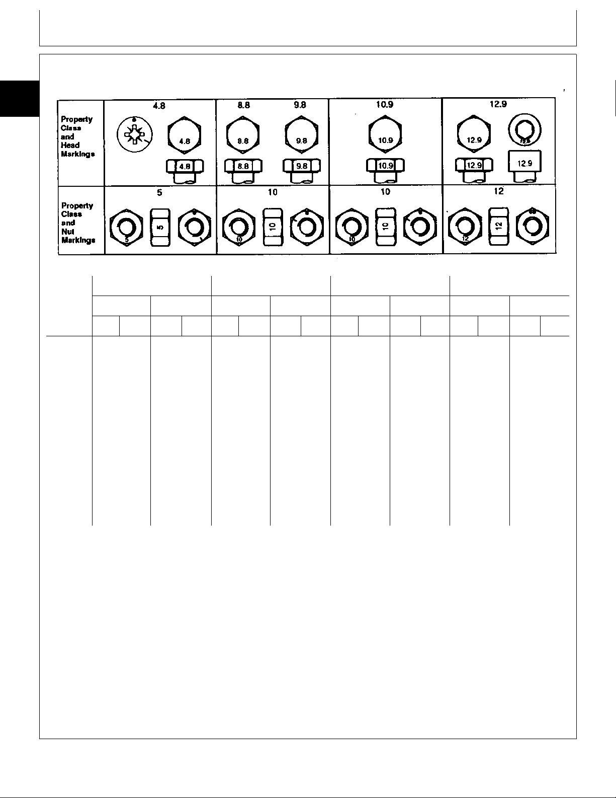
METRIC BOLT AND CAP SCREW TORQUE VALUES
10
10
4
Class 4.8 Class 8.8 or 9.8 Class 10.9 Class 12.9
TS1163 -19-04MAR91
Size Lubricated
N·m lb-ft N·m lb-ft N·m lb-ft N·m lb-ft N·m lb-ft N·m lb-ft N·m lb-ft N·m lb-ft
M6 4.8 3.5 6 4.5 9 6.5 11 8.5 13 9.5 17 12 15 11.5 19 14.5
M8 12 8.5 15 11 22 16 28 20 32 24 40 30 37 28 47 35
M10 23 17 29 21 43 32 55 40 63 47 80 60 75 55 95 70
M12 40 29 50 37 75 55 95 70 110 80 140 105 130 95 165 120
M14 63 47 80 60 120 88 150 110 175 130 225 165 205 150 260 190
M16 100 73 125 92 190 140 240 175 275 200 350 225 320 240 400 300
M18 135 100 175 125 260 195 330 250 375 275 475 350 440 325 560 410
M20 190 140 240 180 375 275 475 350 530 400 675 500 625 460 800 580
M22 260 190 330 250 510 375 650 475 725 540 925 675 850 625 1075 800
M24 330 250 425 310 650 475 825 600 925 675 1150 850 1075 800 1350 1000
M27 490 360 625 450 950 700 1200 875 1350 1000 1700 1250 1600 1150 2000 1500
M30 675 490 850 625 1300 950 1650 1200 1850 1350 2300 1700 2150 1600 2700 2000
M33 900 675 1150 850 1750 1300 2200 1650 2500 1850 3150 2350 2900 2150 3700 2750
M36 1150 850 1450 1075 2250 1650 2850 2100 3200 2350 4050 3000 3750 2750 4750 3500
a
DO NOT use these values if a different torque value
or tightening procedure is given for a specific
application. Torque values listed are for general use
Dry
a
Lubricated
a
Dry
a
Lubricated
a
Dry
a
Lubricated
a
Dry
a
Make sure fasteners threads are clean and that you
properly start thread engagement. This will prevent
them from failing when tightening.
only. Check tightness of fasteners periodically.
Tighten plastic insert or crimped steel-type lock nuts
Shear bolts are designed to fail under predetermined
loads. Always replace shear bolts with identical
property class.
to approximately 50 percent of the dry torque shown
in the chart, applied to the nut, not to the bolt head.
Tighten toothed or serrated-type lock nuts to the full
torque value.
Fasteners should be replaced with the same or
higher property class. If higher property class
fasteners are used, these should only be tightened to
the strength of the original.
a
“Lubricated” means coated with a lubricant such as engine oil, or
fasteners with phosphate and oil coatings. “Dry” means plain or zinc
plated without any lubrication.
DX,TORQ2 -19-16APR92
CTM5 (20OCT92) 10-10-4 K Series Air Cooled Engine
220596
PN=13
Page 22
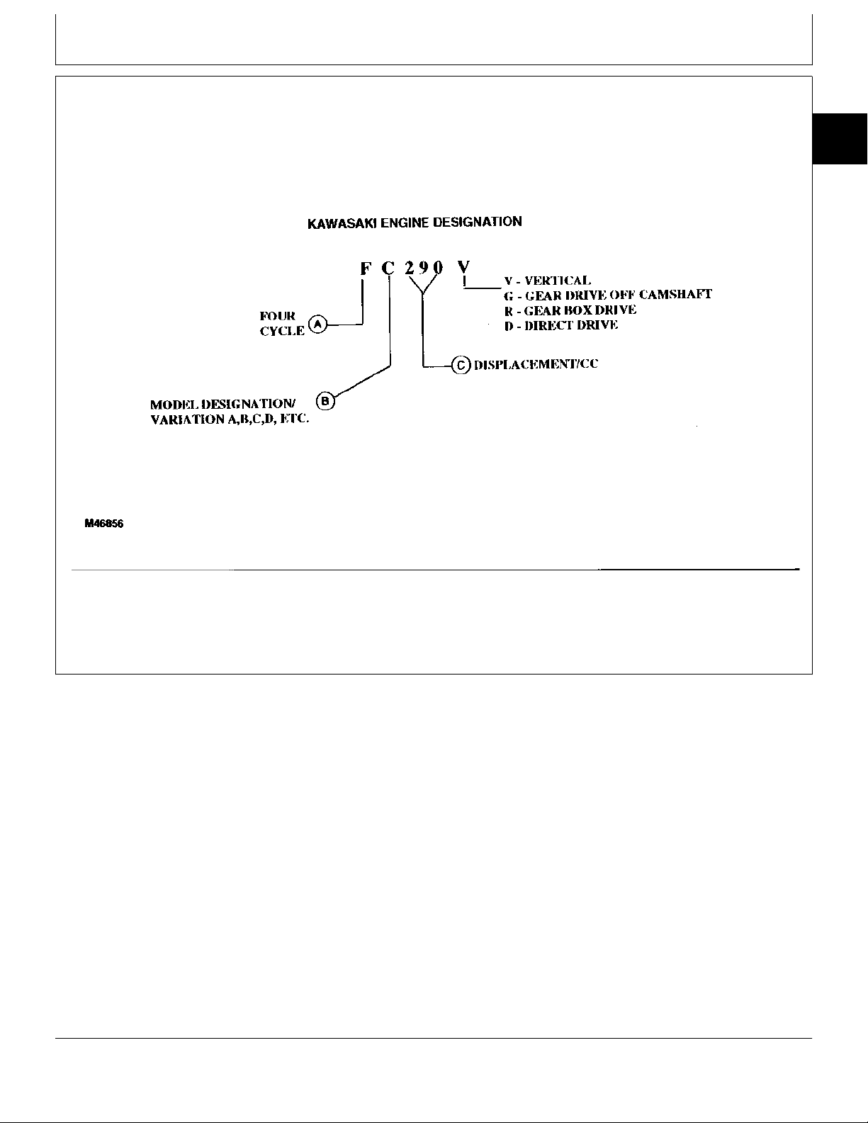
ENGINE DESIGNATION (KAWASAKI)
Group 15
Serial Number Locations
10
15
1
A—Four Cycle C—Displacement R—Gear Box Drive V—Vertical
B—Model Designation D—Direct Drive G—Gear Drive Off Camshaft
MX1020A1,A12 -19-21OCT92
M46856 -19-15OCT92
CTM5 (20OCT92) 10-15-1 K Series Air Cooled Engine
220596
PN=14
Page 23
Serial Number Locations/Serial Number Location
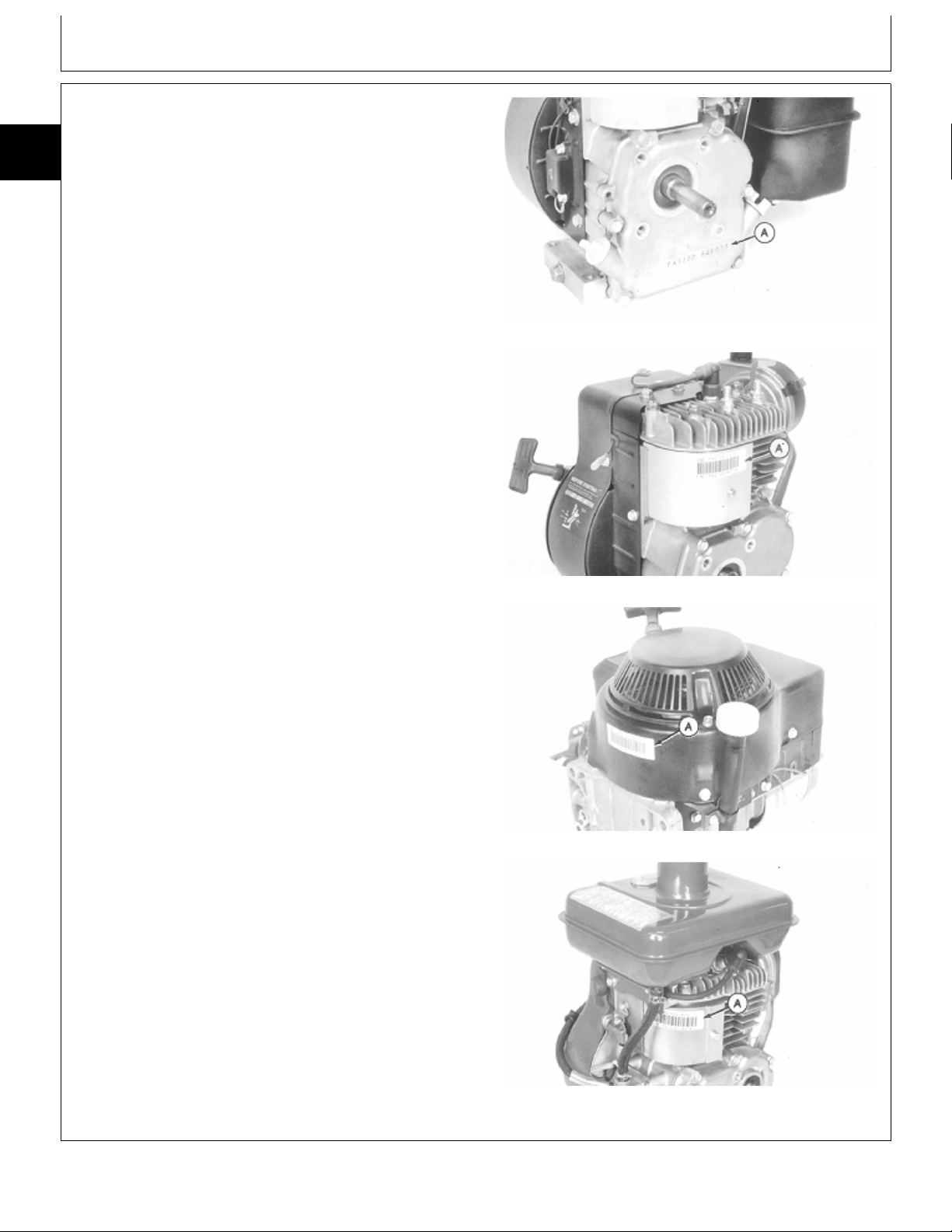
ENGINE SERIAL NUMBER LOCATION
10
The complete serial number (A) is used to identify the
15
engine model, series, configuration, and serial number
2
range. Have this number available when referring to a
particular engine or requesting parts or service
information.
M80492 -UN-07JUN91M80493 -UN-07JUN91M80494 -UN-07JUN91M80495 -UN-07JUN91
FA130D
FA210D
FA210V
FG150D/FG150G
MX,1015A1,A1 -19-21OCT92
CTM5 (20OCT92) 10-15-2 K Series Air Cooled Engine
220596
PN=15
Page 24
Serial Number Locations/Serial Number Location
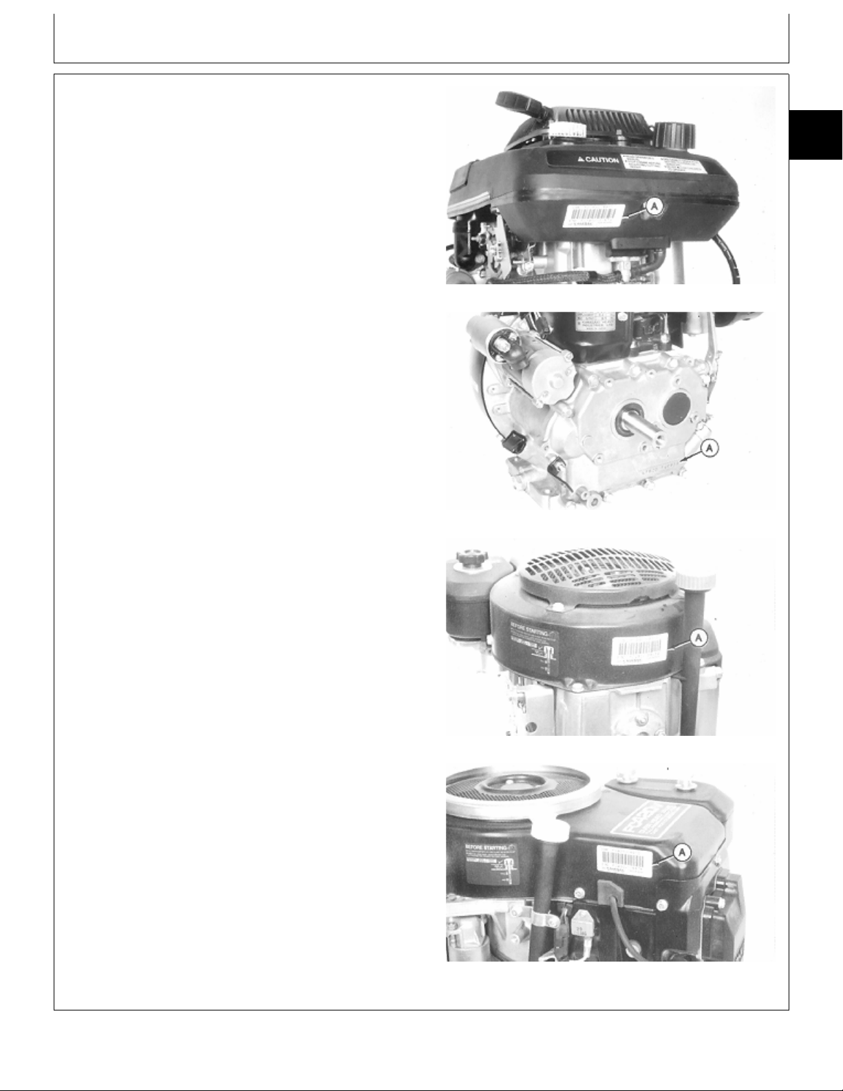
SERIAL NUMBER LOCATION—CONTINUED
A—Serial Number Location
10
15
3
M80496 -UN-07JUN91M80497 -UN-07JUN91M80498 -UN-07JUN91M80499 -UN-07JUN91
FC150V
KF82D/FZ340D
FC290V
FC400V/FC420V
MX,1015A1,A2 -19-21OCT92
CTM5 (20OCT92) 10-15-3 K Series Air Cooled Engine
220596
PN=16
Page 25
Serial Number Locations/Serial Number Location
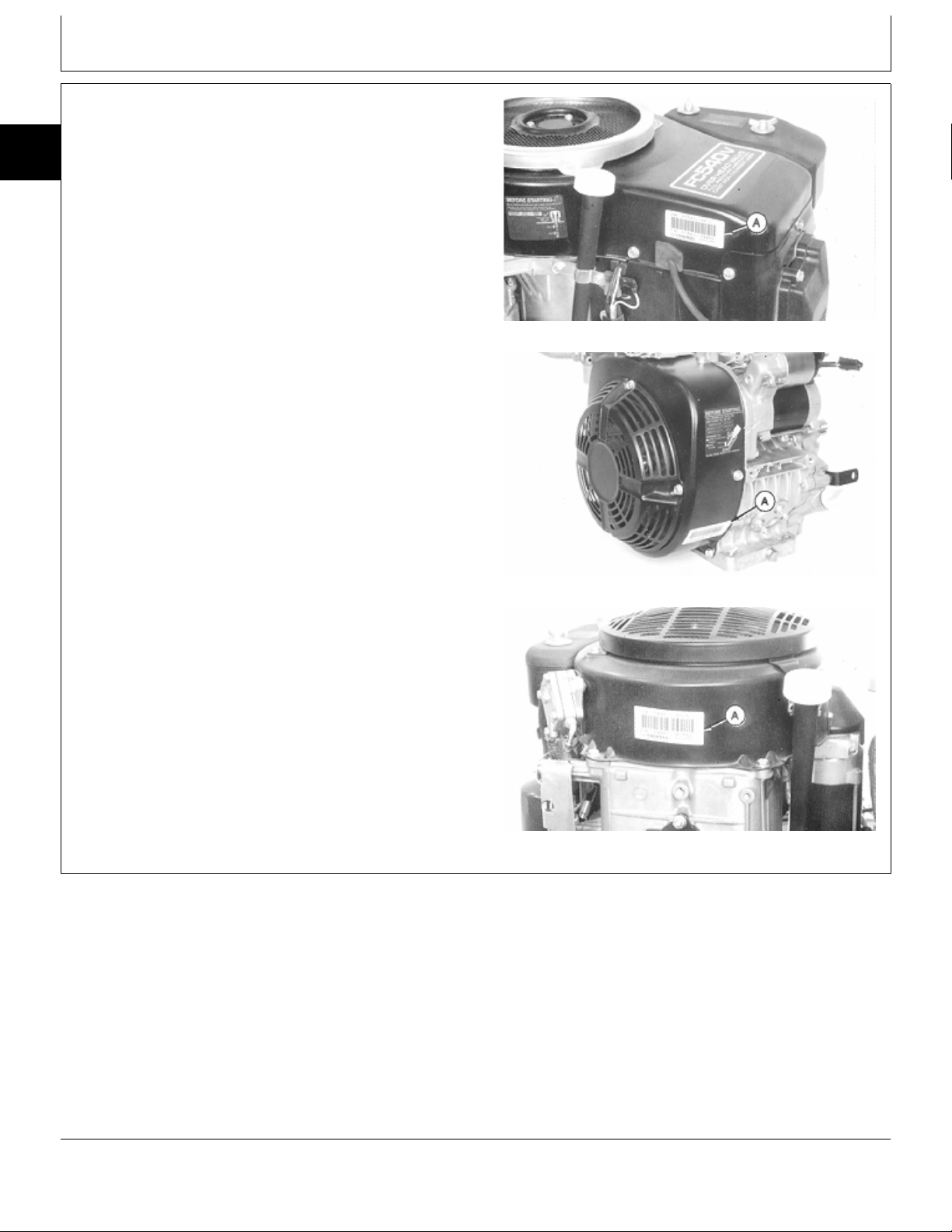
SERIAL NUMBER LOCATION—CONTINUED
10
15
4
A—Serial Number Location
M80500 -UN-07JUN91M80501 -UN-07JUN91M80502 -UN-07JUN91
FC540V
FE290D/FE290R
FB460V
MX,1015A1,A3 -19-21OCT92
CTM5 (20OCT92) 10-15-4 K Series Air Cooled Engine
220596
PN=17
Page 26
Serial Number Locations/Serial Number Location
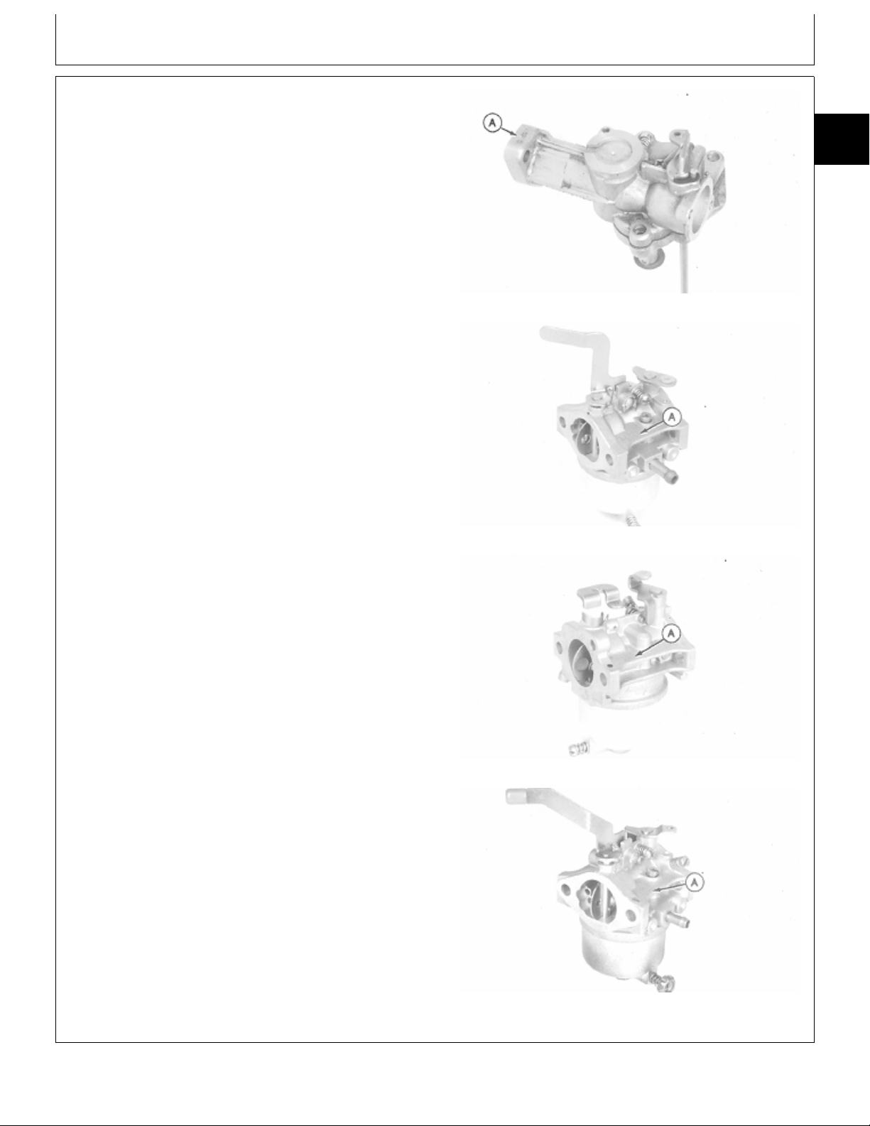
CARBURETOR SERIAL NUMBER LOCATION
NOTE: FA130D carburetor shown is used on
FA130D-AS16/AS19 and FA210D-AS20 engines.
FA130D-AN00 carburetor not shown.
FA210D carburetor shown is used on
FA210D-AS17/BS17/CS17 engines.
FA210D-AS19-01 carburetor not shown.
The serial number (A) is used to identify the carburetor.
Have this number available when requesting parts or
service information.
10
15
5
M80503 -UN-07JUN91M80504 -UN-07JUN91M80505 -UN-07JUN91M80506 -UN-07JUN91
FA130D
FA210D
FA210V
FG150G/FG150D
MX,1015A1,A4 -19-21OCT92
CTM5 (20OCT92) 10-15-5 K Series Air Cooled Engine
220596
PN=18
Page 27
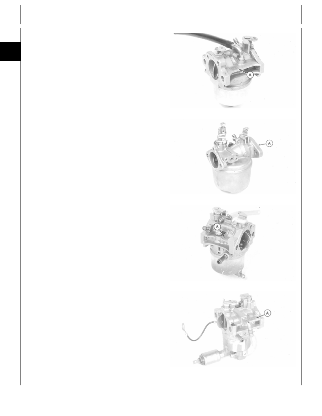
CARBURETOR SERIAL NUMBER
LOCATION—CONTINUED
10
15
6
A—Serial Number Location
Serial Number Locations/Serial Number Location
M80507 -UN-07JUN91M80508 -UN-07JUN91M80509 -UN-07JUN91M80510 -UN-07JUN91
FC150V
KF82D/FZ340D
FC290V
FC400V/FC420V
MX,1015A1,A5 -19-21OCT92
CTM5 (20OCT92) 10-15-6 K Series Air Cooled Engine
220596
PN=19
Page 28
Serial Number Locations/Serial Number Location
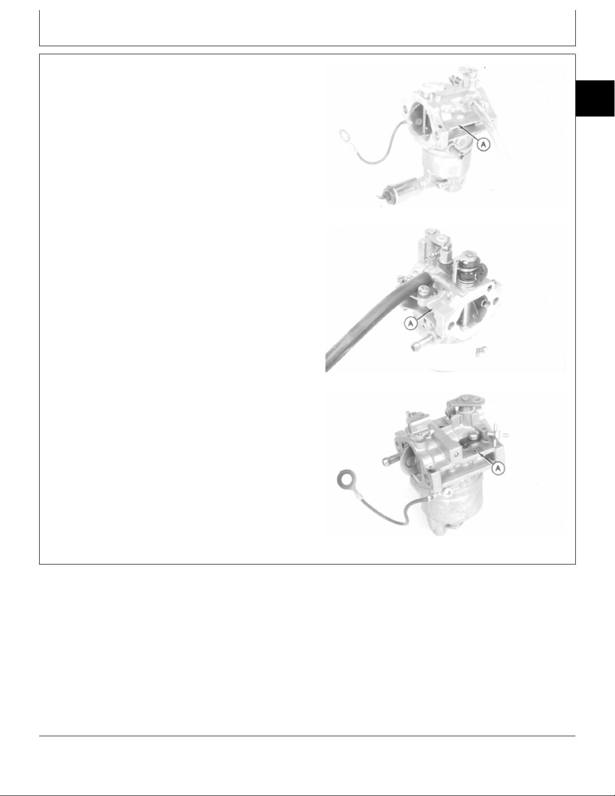
CARBURETOR SERIAL NUMBER
LOCATION—CONTINUED
A—Serial Number Location
10
15
7
M80511 -UN-07JUN91M80512 -UN-07JUN91M80513 -UN-07JUN91
FC540V
FE290D/FE290R
FB460V
MX,1015A1,A6 -19-21OCT92
CTM5 (20OCT92) 10-15-7 K Series Air Cooled Engine
220596
PN=20
Page 29

10
15
8
Serial Number Locations/Serial Number Location
CTM5 (20OCT92) 10-15-8 K Series Air Cooled Engine
220596
PN=21
Page 30
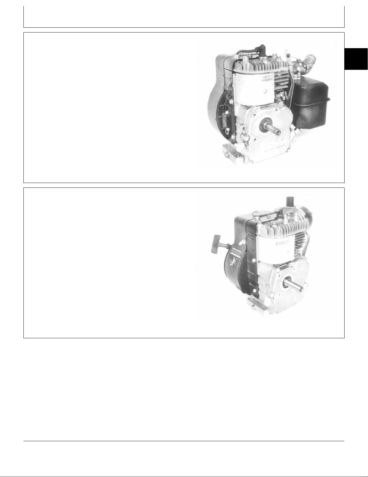
FA130D ENGINE FEATURES
Group 20
Features
•2.3 kW (3.1 hp)
•Pulse Pump carburetor (FA130D-AS16/AS19)
Float type carburetor (FA130D-AN00)
•Two stage air filter with dry paper filter
and foam precleaner (FA130D-AS16)
Single stage foam air filter (FA130D-AN00)
•Side valves
•Horizontal crankshaft
•Aluminum block
•Splash lubrication
•Low oil level sensor (FA130D-AN00)
•Electronic ignition
•Recoil starter
FA210D ENGINE FEATURES
•3.9 kW (5.2 hp)
•Fuel pump (FA210D-AS17/BS17/CS17)
•Pulse pump carburetor (FA210D-AS20)
Float type carburetor
(FA210D-AS17/BS17/CS17 & FA210D-AS19-01)
•Two stage air filter with dry paper
filter and foam precleaner
•Side valves
•Compression release mechanism
(FA210D-AS20)
•Horizontal crankshaft
•Aluminum block
•Splash lubrication
•Electronic ignition
•Recoil starter
10
20
1
M80514 -UN-07JUN91
MX,1020A1,A1 -19-21OCT92
M80515 -UN-07JUN91
MX,1020A1,A2 -19-21OCT92
CTM5 (20OCT92) 10-20-1 K Series Air Cooled Engine
220596
PN=22
Page 31

FA210V ENGINE FEATURES
10
•4.5 kW (6 hp)
20
•Float type carburetor
2
•Two stage air filter with dry paper
filter and foam precleaner
•Side valves
•Compression release mechanism
•Vertical crankshaft
•Aluminum block
•Splash lubrication
•Electronic ignition
•Recoil starter
Features/Engine Features
M80516 -UN-07JUN91
MX,1020A1,A3 -19-21OCT92
FG150G/FG150D ENGINE FEATURES
NOTE: Engines are the same except FG150G engine is
camshaft driven and FG150D engine is
crankshaft driven.
•2.7 kW (3.6 hp)
•Float type carburetor
•Two stage air filter with dry paper
filter and foam precleaner
•Side valves
•Horizontal crankshaft
•Aluminum block
•Cast-iron cylinder liner
•Electronic ignition
•Recoil starter
FG150G Shown
M80517 -UN-07JUN91
MX,1020A1,A4 -19-21OCT92
CTM5 (20OCT92) 10-20-2 K Series Air Cooled Engine
220596
PN=23
Page 32

FC150V ENGINE FEATURES
Features/Engine Features
•3.4 kW (4.5 hp)
•3.7 kW (5.0 hp) (FS01 and ES06)
•Float type carburetor
•Two stage air filter with dry paper
filter and foam precleaner
•Flywheel brake (option)
•Overhead valves
•Compression release mechanism
•Vertical crankshaft
•Aluminum block
•Cast-iron cylinder liner
•Splash (AS00 and AS01)
•Full pressure lubrication
•Oil filter (optional)
•Electronic ignition
•Regulated charging system
•Recoil starter
•Electric starter (option)
10
20
3
M80518 -UN-07JUN91
KF82D/FZ340D ENGINE FEATURES
•6.3 kW (8.5 hp)
•Float type carburetor
•Two stage air filter with dry paper
filter and foam precleaner
•Side valves
•Horizontal crankshaft
•Dynamic balancer shaft
•Cast-iron cylinder block
•Aluminum crankcase
•Splash lubrication
•CDI ignition
•Regulated charging system
•Electric starter
MX,1020A1,A5 -19-21OCT92
M80519 -UN-07JUN91
MX,1020A1,A6 -19-21OCT92
CTM5 (20OCT92) 10-20-3 K Series Air Cooled Engine
220596
PN=24
Page 33

FC290V ENGINE FEATURES
10
•6.7 kW (9 hp)
20
•Float type carburetor
4
•Two stage air filter with dry paper
filter and foam precleaner
•Overhead valves
•Compression release mechanism
•Vertical crankshaft with reciprocating
balancer
•Aluminum block
•Cast-iron cylinder liner
•Splash lubrication
•Electronic ignition
•Regulated charging system
•Recoil starter
•Electric starter (optional)
Features/Engine Features
M80213 -UN-19JUN91
MX,1020A1,A7 -19-21OCT92
FC400V ENGINE FEATURES
•9.3 kW (12.5 hp)
•Float type carburetor
•Two stage air-filter with dry paper
filter and foam precleaner
•Overhead valves
•Compression release mechanism
•Vertical crankshaft with reciprocating
balancer
•Aluminum block
•Cast-iron cylinder liner
•Full pressure lubrication
•Oil filter
•Solid-state ignition
•Regulated charging system
•Recoil start
•Electric starter (optional)
M80214 -UN-19JUN91
MX,1020A1,A8 -19-21OCT92
CTM5 (20OCT92) 10-20-4 K Series Air Cooled Engine
220596
PN=25
Page 34

FC420V ENGINE FEATURES
Features/Engine Features
•10.4 kW (14 hp)
•Float type carburetor
•Two stage air-filter with dry paper
filter and foam precleaner
•Overhead valves
•Compression release mechanism
•Vertical crankshaft with reciprocating
balancer
•Aluminum block
•Cast-iron cylinder liner
•Full pressure lubrication
•Oil filter
•Solid-state ignition
•Regulated charging system
•Recoil start
•Electric starter (optional)
FC540V ENGINE FEATURES
•12.6 kW (17 hp)
•13 kW (17.5 hp) (Engine version AS12)
•Float type carburetor
•Two stage air filter with dry paper
filter and foam precleaner
•Overhead valves
•Compression release mechanism
•Vertical crankshaft with reciprocating balancer
•Aluminum block
•Cast-iron cylinder liner
•Full pressure lubrication
•Oil filter
•Solid-state ignition
•Regulated charging system
•Electric starter
10
20
5
M80214 -UN-19JUN91
MX,1020A1,A8A -19-21OCT92
M80215 -UN-19JUN91
MX,1020A1,A9 -19-21OCT92
CTM5 (20OCT92) 10-20-5 K Series Air Cooled Engine
220596
PN=26
Page 35

Features/Engine Features
FE290D/FE290R ENGINE FEATURES
10
NOTE: Engines are the same except, FE290R can be
20
6
•7.5 kW (10 hp)
•Float type carburetor
•Overhead valves
•Compression release mechanism
•Horizontal crankshaft with reciprocating
balancer
•Aluminum block
•Cast-iron cylinder liner
•Full pressure lubrication
•Oil filter (optional)
•Solid-state ignition
•Regulated charging system
•Recoil starter (optional)
•Electric starter
equipped with a reduction gearbox. Gearbox
attaches to crankcase cover.
M80216 -UN-19JUN91
FB460V ENGINE FEATURES
•9.3 kW (12.5 hp)
•Fuel pump
•Float type carburetor
•Two stage air filter with dry paper
filter and foam precleaner
•Side valves
•Compression release mechanism
•Vertical crankshaft with reciprocating
balancer
•Aluminum block
•Cast-iron cylinder liner
•Full pressure lubrication
•Oil filter (optional)
•Electronic ignition
•Regulated charging system
•Recoil starter
•Electric starter (optional)
MX,1020A1,A10 -19-21OCT92
MX,1020A1,A11 -19-21OCT92
CTM5 (20OCT92) 10-20-6 K Series Air Cooled Engine
220596
PN=27
Page 36

Page
Group 00—Engine Application and Repair
Specifications
Engine Application Chart . . . . . . . . . . . . 20-00-1
Repair Specifications
FA130D . . . . . . . . . . . . . . . . . . . . . . 20-00-2
FA210D . . . . . . . . . . . . . . . . . . . . . . 20-00-4
Group 05—Fuel and Air Systems—FA130D
Service Parts Kits . . . . . . . . . . . . . . . . 20-05-1
Remove, Inspect and Install Fuel
Tank—FA130D-AS16/AS19 . . . . . . . . . 20-05-1
Remove and Install Carburetor
FA130D-AS16/AS19 . . . . . . . . . . . . . 20-05-2
FA130D-AN00 . . . . . . . . . . . . . . . . . 20-05-2
Disassemble, Clean, Inspect and
Assemble Carburetor
FA130D-AS16/AS19 . . . . . . . . . . . . . 20-05-3
FA130D-AN00 . . . . . . . . . . . . . . . . . 20-05-4
Service Breather
FA130D-AS16/AS19 . . . . . . . . . . . . . 20-05-5
FA130D-AN00 . . . . . . . . . . . . . . . . . 20-05-6
Service Air Cleaner . . . . . . . . . . . . . . . 20-05-7
Group 06—Fuel and Air Systems—FA210D
Service Parts Kits . . . . . . . . . . . . . . . . 20-06-1
Remove, Inspect and Install Fuel
Tank—FA210D-AS20 . . . . . . . . . . . . . 20-06-1
Remove and Install Fuel
Pump—FA210D-AS17/BS17/CS17 . . . . 20-06-2
Remove and Install Carburetor
FA210D-AS20 . . . . . . . . . . . . . . . . . 20-06-2
FA210D-AS17/BS17/CS17 . . . . . . . . . 20-06-3
FA210D-AS19-01 . . . . . . . . . . . . . . . 20-06-4
Disassemble, Clean, Inspect and
Assemble Carburetor
FA210D-AS20 . . . . . . . . . . . . . . . . . 20-06-5
FA210D-AS19-01/AS17/BS17/CS17 . . . 20-06-6
R & I Intake Manifold -
A210D-AS19-01/AS17/BS17/CS17 . . . . 20-06-10
Service Breather
FA210D-AS20 . . . . . . . . . . . . . . . . . 20-06-10
FA210D-AS19-01 . . . . . . . . . . . . . . . 20-06-11
FA210D-AS17/BS17/CS17 . . . . . . . . . 20-06-11
Service Air Cleaner . . . . . . . . . . . . . . . 20-06-12
Section 20
FA130D and FA210D
Contents
Page
20
Group 10—Blower Housing and Flywheel
Remove and Install Blower Housing
FA130D and FA210D-AS20 . . . . . . . . 20-10-1
FA210D-AS19-01/AS17/BS17/CS17 . . . 20-10-2
Flywheel Screen Adjustment . . . . . . . . . 20-10-2
Remove and Install Flywheel
FA130D and FA210D-AS20 . . . . . . . . 20-10-3
FA210D-AS19-01/AS17/BS17/CS17 . . . 20-10-3
Group 15—Cylinder Head
Other Material . . . . . . . . . . . . . . . . . . . 20-15-1
Remove and Install Cylinder Head . . . . . 20-15-2
Inspect Cylinder Head . . . . . . . . . . . . . . 20-15-3
Group 20—Cylinder Block, Valves and Internal
Components
Other Materials . . . . . . . . . . . . . . . . . . 20-20-1
Service Parts Kits . . . . . . . . . . . . . . . . 20-20-1
Remove and Install Valves and Springs . . 20-20-2
Inspect Valve Springs . . . . . . . . . . . . . . 20-20-3
Inspect Valve Guides . . . . . . . . . . . . . . 20-20-3
Recondition Valve Seats . . . . . . . . . . . . 20-20-4
Check Valve-To-Tappet Clearance . . . . . 20-20-5
Remove and Install Crankcase Cover . . . 20-20-6
Camshaft
Remove and Install . . . . . . . . . . . . . . 20-20-6
Inspect . . . . . . . . . . . . . . . . . . . . . . 20-20-7
Inspect Plain Bearings . . . . . . . . . . . . 20-20-7
Inspect Automatic Compression Release . 20-20-8
Remove, Inspect and Install Tappets . . . . 20-20-8
Piston and Connecting Rod
Remove and Install . . . . . . . . . . . . . . 20-20-9
Disassemble, Inspect and Assemble . . . 20-20-10
Inspect Piston . . . . . . . . . . . . . . . . . . . 20-20-11
Inspect Connecting Rod . . . . . . . . . . . . 20-20-13
Piston Rings
Remove and Install . . . . . . . . . . . . . . 20-20-14
Check End Gap . . . . . . . . . . . . . . . . 20-20-14
Crankshaft
Remove, Inspect and Install . . . . . . . . 20-20-15
Inspect Plain Bearings . . . . . . . . . . . . 20-20-16
Continued on next page
CTM5 (20OCT92) 20-1 K Series Air Cooled Engine
220596
PN=488
Page 37

Crankshaft—Continued
Replace Bearing Shell . . . . . . . . . . . . 20-20-16
Inspect Ball Bearing . . . . . . . . . . . . . 20-20-17
Check Alignment (TIR) . . . . . . . . . . . . 20-20-17
20
Measure End Play . . . . . . . . . . . . . . . 20-20-17
Inspect
Oil Seals . . . . . . . . . . . . . . . . . . . . . 20-20-18
Cylinder Block . . . . . . . . . . . . . . . . . 20-20-18
Rebore Cylinder Block . . . . . . . . . . . . . 20-20-19
Inspect and Replace Oil Splasher . . . . . . 20-20-20
Check Low Oil Level Sensor . . . . . . . . . 20-20-20
Inspect and Replace Governor . . . . . . . . 20-20-21
Inspect and Replace Governor Shaft . . . . 20-20-22
Governor Adjustment
FA130D-AS16/AS19 & FA210D-AS20 . . 20-20-22
FA210D-AS19-01/AS17/BS17/CS17 . . . 20-20-23
Group 25—Ignition and Charging System
Remove and Install Armature with Coil . . 20-25-1
Adjust Armature Air Gap . . . . . . . . . . . . 20-25-1
Replace Ignitor—FA130D and
FA210D-AS20 . . . . . . . . . . . . . . . . . 20-25-2
Contents
Page
Group 30—Starting Systems—FA130D
Recoil Starter—FA130D-AS16/AS19
Disassemble . . . . . . . . . . . . . . . . . . 20-30-1
Inspect . . . . . . . . . . . . . . . . . . . . . . 20-30-2
Replace Spring . . . . . . . . . . . . . . . . . 20-30-3
Assemble . . . . . . . . . . . . . . . . . . . . 20-30-3
Recoil Starter—FA130D-AN00
Disassemble . . . . . . . . . . . . . . . . . . 20-30-4
Inspect . . . . . . . . . . . . . . . . . . . . . . 20-30-6
Replace Spring . . . . . . . . . . . . . . . . . 20-30-7
Assemble . . . . . . . . . . . . . . . . . . . . 20-30-7
Group 31—Starting Systems—FA210D
Recoil Starter
Disassemble . . . . . . . . . . . . . . . . . . 20-31-1
Inspect . . . . . . . . . . . . . . . . . . . . . . 20-31-2
Replace Spring . . . . . . . . . . . . . . . . . 20-31-4
Assemble . . . . . . . . . . . . . . . . . . . . 20-31-4
CTM5 (20OCT92) 20-2 K Series Air Cooled Engine
220596
PN=489
Page 38

Group 00
Engine Application and Repair Specifications
ENGINE APPLICATIONS CHART
Refer to the engine application chart to identify
product-model/engine type-model relationship.
Machine Engine Model No.
3K Lawn Edger . . . . . . . . . . . . . . . . . . . . . . . . . . . . . . . . . . . . . . . . . . . . . . . . . . . . . . . FA130D-AS16
E35 Lawn Edger . . . . . . . . . . . . . . . . . . . . . . . . . . . . . . . . . . . . . . . . . . . . . . . . . . . . . . . FA130D-AS19
1000/1400 Generators . . . . . . . . . . . . . . . . . . . . . . . . . . . . . . . . . . . . . . . . . . . . . . . . . . . FA130D-AN00
20SR7 Reel Mower . . . . . . . . . . . . . . . . . . . . . . . . . . . . . . . . . . . . . . . . . . . . . . . . . . . . . FA130D-AS16
519 Walk-Behind Vertical Mower . . . . . . . . . . . . . . . . . . . . . . . . . . . . . . . . . . . . . . . . . . . . FA210D-AS20
529 Vacuum Blower . . . . . . . . . . . . . . . . . . . . . . . . . . . . . . . . . . . . . . . . . . . . . . . . . . FA210D-AS19-01
Power Pak Material Collection System
(Engine S.N. —254693) . . . . . . . . . . . . . . . . . . . . . . . . . . . . . . . . . . . . . . . . . . . . . . FA210D-AS17
(Engine S.N. 254694—289197) . . . . . . . . . . . . . . . . . . . . . . . . . . . . . . . . . . . . . . . . . . . FA210D-BS17
(Engine S.N. 289198— ) . . . . . . . . . . . . . . . . . . . . . . . . . . . . . . . . . . . . . . . . . . . . . . FA210D-CS17
MX,2000A1,A1 -19-21OCT92
20
00
1
CTM5 (20OCT92) 20-00-1 K Series Air Cooled Engine
220596
PN=28
Page 39

Engine Application and Repair Specifications/Repair Specifications
FA130D REPAIR SPECIFICATIONS
GROUP 10—BLOWER HOUSING AND FLYWHEEL
Item Specification
Flywheel Nut Torque . . . . . . . . . . . . . . . . . . . . . . . . . . . . . . . . . . . . . . . . . . . . . . . . . . 60 N·m (44 lb-ft)
20
GROUP 15—CYLINDER HEAD
00
2
Cylinder Head
Maximum Cylinder Head Warp . . . . . . . . . . . . . . . . . . . . . . . . . . . . . . . . . . . . . . . . 0.25 mm (0.010 in.)
Cap Screw Torque In Sequence
Initial Torque . . . . . . . . . . . . . . . . . . . . . . . . . . . . . . . . . . . . . . . . . . . . . . . . . . . . . . 10 N·m (89 lb-in.)
Final Torque . . . . . . . . . . . . . . . . . . . . . . . . . . . . . . . . . . . . . . . . . . . . . . . . . . . . . 21 N·m (186 lb-in.)
Spark Plug Torque . . . . . . . . . . . . . . . . . . . . . . . . . . . . . . . . . . . . . . . . . . . . . . . . . . 17 N·m (156 lb-in.)
GROUP 20—CYLINDER BLOCK, VALVES AND INTERNAL COMPONENTS
Valve Clearance (cold)
Intake . . . . . . . . . . . . . . . . . . . . . . . . . . . . . . . . . . . . . . . . . . . . . . . 0.12—0.18 mm (0.005—0.007 in.)
Exhaust . . . . . . . . . . . . . . . . . . . . . . . . . . . . . . . . . . . . . . . . . . . . . . 0.10—0.34 mm (0.004—0.013 in.)
Valves and Springs
Minimum Spring Free Length . . . . . . . . . . . . . . . . . . . . . . . . . . . . . . . . . . . . . . . . 23.50 mm (0.930 in.)
Maximum Valve Guide I.D.
Intake . . . . . . . . . . . . . . . . . . . . . . . . . . . . . . . . . . . . . . . . . . . . . . . . . . . . . . 6.10 mm (0.2401 in.)
Exhaust . . . . . . . . . . . . . . . . . . . . . . . . . . . . . . . . . . . . . . . . . . . . . . . . . . . . . 6.09 mm (0.2397 in.)
Minimum Valve Stem Diameter . . . . . . . . . . . . . . . . . . . . . . . . . . . . . . . . . . . . . . . 5.95 mm (0.234 in.)
Maximum Valve Stem Bend . . . . . . . . . . . . . . . . . . . . . . . . . . . . . . . . . . . . . . . . . . 0.03 mm (0.001 in.)
Valve Seating Surface Angle . . . . . . . . . . . . . . . . . . . . . . . . . . . . . . . . . . . . . . . . . . . . . . . . . . . . 45˚
Valve Seating Width . . . . . . . . . . . . . . . . . . . . . . . . . . . . . . . . . . . . . . 1.00—1.60 mm (0.039—0.063 in.)
Valve Margin . . . . . . . . . . . . . . . . . . . . . . . . . . . . . . . . . . . . . . . . . . . . . . . . . . . . 0.60 mm (0.020 in.)
Valve Narrowing Angle . . . . . . . . . . . . . . . . . . . . . . . . . . . . . . . . . . . . . . . . . . . . . . . . . . . . . . . . 30˚
Continued on next page
MX,2000A1,A2 -19-21OCT92
CTM5 (20OCT92) 20-00-2 K Series Air Cooled Engine
220596
PN=29
Page 40

Engine Application and Repair Specifications/Repair Specifications
GROUP 20—CYLINDER BLOCK, VALVES AND INTERNAL COMPONENTS—CONTINUED
Item Specification
Crankcase Cover
Oil Capacity . . . . . . . . . . . . . . . . . . . . . . . . . . . . . . . . . . . . . . . . . . . . . . . . . . . . . . . . 0.5 L (1.06 pt)
Cap Screw Torque . . . . . . . . . . . . . . . . . . . . . . . . . . . . . . . . . . . . . . . . . . . . . . . . . . 6 N·m (53 lb-in.)
Drain Plug Torque . . . . . . . . . . . . . . . . . . . . . . . . . . . . . . . . . . . . . . . . . . . . . . . . . 14 N·m (121 lb-in.)
Camshaft
Minimum End Journals O.D. . . . . . . . . . . . . . . . . . . . . . . . . . . . . . . . . . . . . . . . . 11.94 mm (0.469 in.)
Minimum Lobe Height . . . . . . . . . . . . . . . . . . . . . . . . . . . . . . . . . . . . . . . . . . . . . 23.25 mm (0.915 in.)
Maximum Cover and Crankcase Bearing I.D. . . . . . . . . . . . . . . . . . . . . . . . . . . . . . 12.04 mm (0.474 in.)
Piston
Maximum Ring Groove Clearance . . . . . . . . . . . . . . . . . . . . . . . . . . . . . . . . . . . . . . 0.15 mm (0.006 in.)
Minimum Ring End Gap . . . . . . . . . . . . . . . . . . . . . . . . . . . . . . . . . . . . . . . . . . . . 0.18 mm (0.007 in.)
Maximum Ring End Gap . . . . . . . . . . . . . . . . . . . . . . . . . . . . . . . . . . . . . . . . . . . . 1.00 mm (0.039 in.)
Minimum Pin O.D. . . . . . . . . . . . . . . . . . . . . . . . . . . . . . . . . . . . . . . . . . . . . . . . 12.98 mm (0.511 in.)
Maximum Pin Bore I.D. . . . . . . . . . . . . . . . . . . . . . . . . . . . . . . . . . . . . . . . . . . . . 13.04 mm (0.513 in.)
Maximum Piston-to-Piston Pin Clearance . . . . . . . . . . . . . . . . . . . . . . . . . . . . . . . . . 0.05 mm (0.002 in.)
Minimum Piston O.D. . . . . . . . . . . . . . . . . . . . . . . . . . . . . . . . . . . . 61.86—61.89 mm (2.435—2.437 in.)
Piston-to-Cylinder Bore Clearance
Maximum . . . . . . . . . . . . . . . . . . . . . . . . . . . . . . . . . . . . . . . . . . . . . . . . . . . 0.25 mm (0.0098 in.)
Standard . . . . . . . . . . . . . . . . . . . . . . . . . . . . . . . . . . . . . . . . 0.087—0.137 mm (0.0034—0.0054 in.)
Connecting Rod
Maximum Crankshaft Bearing I.D. . . . . . . . . . . . . . . . . . . . . . . . . . . . . . . . . . . . . . 24.05 mm (0.947 in.)
Maximum Piston Pin Bearing I.D. . . . . . . . . . . . . . . . . . . . . . . . . . . . . . . . . . . . . . 13.04 mm (0.513 in.)
Maximum Connecting Rod-to-Piston Pin Clearance . . . . . . . . . . . . . . . . . . . . . . . . . . 0.05 mm (0.002 in.)
Maximum Connecting Rod-to-Crankpin Clearance . . . . . . . . . . . . . . . . . . . . . . . . . . . 0.10 mm (0.004 in.)
End-Cap Screw Torque . . . . . . . . . . . . . . . . . . . . . . . . . . . . . . . . . . . . . . . . . . . . . . 12 N·m (106 lb-in.)
20
00
3
Crankshaft
Minimum Flywheel Side Journal O.D. . . . . . . . . . . . . . . . . . . . . . . . . . . . . . . . . . . 21.97 mm (0.865 in.)
Minimum Connecting Rod Journal O.D. . . . . . . . . . . . . . . . . . . . . . . . . . . . . . . . . . 23.95 mm (0.943 in.)
Maximum Crankcase Plain Bearing I.D. . . . . . . . . . . . . . . . . . . . . . . . . . . . . . . . . . 22.10 mm (0.869 in.)
Maximum T.I.R. . . . . . . . . . . . . . . . . . . . . . . . . . . . . . . . . . . . . . . . . . . . . . . . . . . 0.05 mm (0.002 in.)
End Play . . . . . . . . . . . . . . . . . . . . . . . . . . . . . . . . . . . . . . . . . . . . . . . . . . 0—0.30 mm (0—0.012 in.)
PTO Side Oil Seal Depth . . . . . . . . . . . . . . . . . . . . . . . . . . . . . . . . . . . . . . . . . . . . . . . 4 mm (0.158 in.)
Cylinder Bore
Standard Cylinder Bore I.D. . . . . . . . . . . . . . . . . . . . . . . . . . . . . . . . 61.90—62.00 mm (2.439—2.443 in.)
Maximum Cylinder Bore I.D. . . . . . . . . . . . . . . . . . . . . . . . . . . . . . . . . . . . . . . . . 62.07 mm (2.446 in.)
Low Oil Level Sensor Travel . . . . . . . . . . . . . . . . . . . . . . . . . . . . . . . . . 9.50—15.50 mm (0.374—0.610 in.)
GROUP 25—IGNITION AND CHARGING SYSTEM
Ignition Coil Air Gap . . . . . . . . . . . . . . . . . . . . . . . . . . . . . . . . . . . . . . . . . . . . . . . . 0.50 mm (0.019 in.)
See Ignition Tests in this Group.
MX,2000A1,A3 -19-21OCT92
CTM5 (20OCT92) 20-00-3 K Series Air Cooled Engine
220596
PN=30
Page 41

Engine Application and Repair Specifications/Repair Specifications
FA210D REPAIR SPECIFICATIONS
GROUP 10—BLOWER HOUSING AND FLYWHEEL
Item Specification
Flywheel Nut Torque . . . . . . . . . . . . . . . . . . . . . . . . . . . . . . . . . . . . . . . . . . . . . . . . . . 60 N·m (44 lb-ft)
20
Flywheel Screen Gap . . . . . . . . . . . . . . . . . . . . . . . . . . . . . . . . . . . . . . . . . . 1—3 mm (0.039—0.118 in.)
00
4
GROUP 15—CYLINDER HEAD
Cylinder Head
Maximum Cylinder Head Warp . . . . . . . . . . . . . . . . . . . . . . . . . . . . . . . . . . . . . . . . 0.40 mm (0.015 in.)
Cap Screw Torque In Sequence
Initial Torque . . . . . . . . . . . . . . . . . . . . . . . . . . . . . . . . . . . . . . . . . . . . . . . . . . . . 10 N·m (89 lb-ft)
Final Torque . . . . . . . . . . . . . . . . . . . . . . . . . . . . . . . . . . . . . . . . . . . . . . . . . . . 21 N·m (186 lb-in)
Spark Plug Torque . . . . . . . . . . . . . . . . . . . . . . . . . . . . . . . . . . . . . . . . . . . . . . . . . . 24 N·m (212 lb-in.)
GROUP 20—CYLINDER BLOCK, VALVES AND INTERNAL COMPONENTS
Valve Clearance (cold)
Intake . . . . . . . . . . . . . . . . . . . . . . . . . . . . . . . . . . . . . . . . . . . . . . . 0.12—0.18 mm (0.005—0.007 in.)
Exhaust . . . . . . . . . . . . . . . . . . . . . . . . . . . . . . . . . . . . . . . . . . . . . . 0.12—0.34 mm (0.005—0.013 in.)
Valves and Springs
Minimum Spring Free Length . . . . . . . . . . . . . . . . . . . . . . . . . . . . . . . . . . . . . . . . 23.50 mm (0.930 in.)
Maximum Valve Guide I.D.
Intake . . . . . . . . . . . . . . . . . . . . . . . . . . . . . . . . . . . . . . . . . . . . . . . . . . . . . . . 6.10 mm (0.240 in.)
Exhaust . . . . . . . . . . . . . . . . . . . . . . . . . . . . . . . . . . . . . . . . . . . . . . . . . . . . . . 6.13 mm (0.242 in.)
Maximum Valve Stem Bend . . . . . . . . . . . . . . . . . . . . . . . . . . . . . . . . . . . . . . . . . . 0.03 mm (0.001 in.)
Valve Seat and Face Angle . . . . . . . . . . . . . . . . . . . . . . . . . . . . . . . . . . . . . . . . . . . . . . . . . . . . . 45˚
Valve Seating Width . . . . . . . . . . . . . . . . . . . . . . . . . . . . . . . . . . . . . . . . . . . . . . . 1.30 mm (0.050 in.)
Valve Margin . . . . . . . . . . . . . . . . . . . . . . . . . . . . . . . . . . . . . . . . . . . . . . . . . . . . 0.60 mm (0.020 in.)
Valve Narrowing Angle . . . . . . . . . . . . . . . . . . . . . . . . . . . . . . . . . . . . . . . . . . . . . . . . . . . . . . . . 30˚
Continued on next page
MX,2000A1,A4 -19-21OCT92
CTM5 (20OCT92) 20-00-4 K Series Air Cooled Engine
220596
PN=31
Page 42

Engine Application and Repair Specifications/Repair Specifications
GROUP 20—CYLINDER BLOCK, VALVES AND INTERNAL COMPONENTS—CONTINUED
Item Specification
Crankcase Cover
Oil Capacity . . . . . . . . . . . . . . . . . . . . . . . . . . . . . . . . . . . . . . . . . . . . . . . . . . . . . . . . 0.6 L (1.27 pt)
Cap Screw Torque . . . . . . . . . . . . . . . . . . . . . . . . . . . . . . . . . . . . . . . . . . . . . . . . . 21 N·m (186 lb-in.)
Camshaft
Minimum End Journals O.D. . . . . . . . . . . . . . . . . . . . . . . . . . . . . . . . . . . . . . . . . 12.94 mm (0.509 in.)
Minimum Lobe Height
Intake . . . . . . . . . . . . . . . . . . . . . . . . . . . . . . . . . . . . . . . . . . . . . . . . . . . . . . 26.45 mm (1.041 in.)
Exhaust . . . . . . . . . . . . . . . . . . . . . . . . . . . . . . . . . . . . . . . . . . . . . . . . . . . . . 26.35 mm (1.037 in.)
Maximum Bearing I.D. . . . . . . . . . . . . . . . . . . . . . . . . . . . . . . . . . . . . . . . . . . . . 13.05 mm (0.514 in.)
Piston
Maximum Ring Groove Clearance
Top Ring . . . . . . . . . . . . . . . . . . . . . . . . . . . . . . . . . . . . . . . . . . . . . . . . . . . . . 0.15 mm (0.006 in.)
Second Ring . . . . . . . . . . . . . . . . . . . . . . . . . . . . . . . . . . . . . . . . . . . . . . . . . . 0.13 mm (0.005 in.)
Oil Ring . . . . . . . . . . . . . . . . . . . . . . . . . . . . . . . . . . . . . . . . . . . . . . . . . . . . . 0.12 mm (0.004 in.)
Minimum Ring End Gap . . . . . . . . . . . . . . . . . . . . . . . . . . . . . . . . . . . . . . . . . . . . 0.18 mm (0.007 in.)
Maximum Ring End Gap . . . . . . . . . . . . . . . . . . . . . . . . . . . . . . . . . . . . . . . . . . . . 1.00 mm (0.039 in.)
Minimum Pin O.D. . . . . . . . . . . . . . . . . . . . . . . . . . . . . . . . . . . . . . . . . . . . . . . . 14.98 mm (0.590 in.)
Maximum Pin Bore I.D. . . . . . . . . . . . . . . . . . . . . . . . . . . . . . . . . . . . . . . . . . . . . 15.04 mm (0.593 in.)
Maximum Piston-to-Piston Pin Clearance . . . . . . . . . . . . . . . . . . . . . . . . . . . . . . . . . 0.06 mm (0.003 in.)
Piston O.D. . . . . . . . . . . . . . . . . . . . . . . . . . . . . . . . . . . . . . . . . . . 71.86—71.89 mm (2.829—2.830 in.)
Piston-to-Cylinder Bore Clearance
Maximum . . . . . . . . . . . . . . . . . . . . . . . . . . . . . . . . . . . . . . . . . . . . . . . . . . 0.163 mm (0.0064 in.)
Standard . . . . . . . . . . . . . . . . . . . . . . . . . . . . . . . . . . . . . . . . 0.087—0.137 mm (0.0034—0.0054 in.)
20
00
5
Connecting Rod
Maximum Crankshaft Bearing I.D. . . . . . . . . . . . . . . . . . . . . . . . . . . . . . . . . . . . . . 27.06 mm (1.065 in.)
Maximum Piston Pin Bearing I.D. . . . . . . . . . . . . . . . . . . . . . . . . . . . . . . . . . . . . . 15.04 mm (0.592 in.)
Maximum Connecting Rod-to-Piston Pin Clearance . . . . . . . . . . . . . . . . . . . . . . . . . . 0.06 mm (0.002 in.)
Maximum Connecting Rod-to-Crankpin Clearance . . . . . . . . . . . . . . . . . . . . . . . . . . . 0.12 mm (0.005 in.)
End-Cap Screw Torque . . . . . . . . . . . . . . . . . . . . . . . . . . . . . . . . . . . . . . . . . . . . . . 19 N·m (168 lb-in.)
Crankshaft
Minimum PTO Side Journal O.D. . . . . . . . . . . . . . . . . . . . . . . . . . . . . . . . . . . . . . 24.96 mm (0.983 in.)
Minimum Flywheel Side Journal O.D. . . . . . . . . . . . . . . . . . . . . . . . . . . . . . . . . . . 24.96 mm (0.983 in.)
Minimum Connecting Rod Journal O.D. . . . . . . . . . . . . . . . . . . . . . . . . . . . . . . . . . 26.95 mm (1.061 in.)
Maximum T.I.R. . . . . . . . . . . . . . . . . . . . . . . . . . . . . . . . . . . . . . . . . . . . . . . . . . . 0.05 mm (0.002 in.)
End Play . . . . . . . . . . . . . . . . . . . . . . . . . . . . . . . . . . . . . . . . . . . . . . . . . . 0—0.30 mm (0—0.012 in.)
PTO Side Oil Seal Depth . . . . . . . . . . . . . . . . . . . . . . . . . . . . . . . . . . . . . . . . . . . . . . . 4 mm (0.158 in.)
Crankcase Plain Bearing . . . . . . . . . . . . . . . . . . . . . . . . . . . . . . . . . . . . . . . . . . . . 25.10 mm (0.988 in.)
MX,2000A1,A5 -19-21OCT92
CTM5 (20OCT92) 20-00-5 K Series Air Cooled Engine
220596
PN=32
Page 43

Engine Application and Repair Specifications/Repair Specifications
GROUP 20—CYLINDER BLOCK, VALVES AND INTERNAL COMPONENTS—CONTINUED
Item Specification
Cylinder Bore
Standard Cylinder Bore I.D. . . . . . . . . . . . . . . . . . . . . . . . . . . . . . . . 71.98—72.00 mm (2.834—2.835 in.)
Maximum Cylinder Bore I.D. . . . . . . . . . . . . . . . . . . . . . . . . . . . . . . . . . . . . . . . . 72.06 mm (2.837 in.)
20
GROUP 25—IGNITION AND CHARGING SYSTEM
00
6
Ignition Coil Air Gap . . . . . . . . . . . . . . . . . . . . . . . . . . . . . . . . . . . . . . . . . . . . . . . . 0.30 mm (0.012 in.)
See Ignition Tests in this Group.
MX,2000A1,A6 -19-21OCT92
CTM5 (20OCT92) 20-00-6 K Series Air Cooled Engine
220596
PN=33
Page 44

SERVICE PARTS KITS
The following kits are available through your parts
catalog:
Carburetor Gasket Kit—Engine Number FA130D-AS16
Group 05
Fuel and Air Systems—FA130D
Complete Carburetor
REMOVE, INSPECT AND INSTALL FUEL
TANK—FA130D-AS16/AS19
CAUTION: Gasoline vapor is explosive. Do not
N
expose to spark or flame. Serious personal
injury can result.
1. Remove air cleaner assembly or intake manifold and
gasket (A).
2. Remove choke lever and linkage (C).
3. Remove screws (B) and cap screw and washer (D).
Remove fuel tank and gasket.
4. Inspect fuel tank for cracks or damage. Repair or
replace as necessary.
5. Install fuel tank and gasket.
20
05
1
MX,2005A1,A1 -19-21OCT92
M80231 -UN-11MAR91
A—Intake Manifold and Gasket
B—Screw (3 used)
C—Choke Lever and Linkage
D—Cap Screw and Washer
6. Install choke lever and linkage.
7. Install intake manifold and gasket or air cleaner
assembly.
MX,2005A1,A2 -19-21OCT92
CTM5 (20OCT92) 20-05-1 K Series Air Cooled Engine
220596
PN=34
Page 45

Fuel and Air Systems—FA130D/Remove and Install Carburetor
REMOVE AND INSTALL
CARBURETOR—FA130D-AS16/AS19
1. Remove fuel tank. (See this group.)
2. Remove two nuts and washers (C).
3. Separate carburetor from spacer (A). Remove
20
05
carburetor.
2
4. Disconnect throttle control linkage (B).
5. Remove spacer (A) and gaskets.
6. Make repairs as necessary. (See this group.)
7. Install gaskets and spacer.
8. Connect linkage and install carburetor.
9. Install washers and nuts.
M80232 -UN-11MAR91M80233 -UN-11MAR91
10. Install fuel tank.
REMOVE AND INSTALL
CARBURETOR—FA130D-AN00
1. Remove air cleaner assembly and gasket.
2. Remove nuts and washers (A).
3. Separate carburetor from spacer (D). Remove
carburetor (B).
4. Disconnect throttle control linkage.
5. Remove spacer(D) and gaskets (C and E).
6. Make repairs as necessary. (See this group.)
7. Install gaskets and spacer.
8. Connect linkage and install carburetor.
MX,2005A1,A3 -19-21OCT92
TY15011 -UN-06DEC89
A—Mounting Nuts and Washers
B—Carburetor
C—Small Gasket
D—Spacer
E—Large Gasket
9. Install washers and nuts.
10. Install air cleaner assembly and gasket.
MX,2005A1,A4 -19-21OCT92
CTM5 (20OCT92) 20-05-2 K Series Air Cooled Engine
220596
PN=35
Page 46

Fuel and Air Systems—FA130D/Disassemble, Clean, Inspect and Assemble Carburetor
DISASSEMBLE, CLEAN, INSPECT AND
ASSEMBLE
CARBURETOR—FA130D-AS16/AS19
IMPORTANT: Do not clean holes or passages with
small drill bits or wire.
1. Soak carburetor body and all parts, except gaskets
and plastic rings, in carburetor cleaning solvent for 1/2
hour maximum.
2. Spray all passages with a carburetor cleaning spray to
verify that all internal passages are open.
IMPORTANT: Rinse carburetor body in warm water to
neutralize corrosive action of cleaner
on aluminum.
3. Rinse carburetor with warm water and dry with
compressed air. Do not use rags or paper to dry parts:
lint may plug holes or passages.
4. Inspect all parts for wear or damage, replace as
necessary.
A—Throttle Shaft
B—Choke Shaft
C—Pilot Screw
D—Spring
E—Bushing
F—Spring
G—Idle Screw
H—Screw
I—Gasket
J—Choke Valve
K—Spring
L—Spring Cap
M—Gasket
N—Diaphragm
O—Lower Housing
P—Main Jet
Q—Bushing
R—Strainer
S—Upper Housing
20
05
3
M51767 -UN-07SEP88
MX,2005A1,A5 -19-21OCT92
CTM5 (20OCT92) 20-05-3 K Series Air Cooled Engine
220596
PN=36
Page 47

Fuel and Air Systems—FA130D/Disassemble, Clean, Inspect and Assemble Carburetor
DISASSEMBLE, CLEAN, INSPECT AND
ASSEMBLE CARBURETOR—FA130D-AN00
IMPORTANT: To remove float, use a long nosed
pliers on end of pin (M). Do not strike
opposite end of pin. Damage to pin
holder may result.
20
05
4
1. Soak carburetor body and all parts, except gaskets
and plastic rings, in carburetor cleaning solvent for 1/2
hour maximum.
2. Spray all passages with a carburetor cleaning spray to
verify that all internal passages are open.
IMPORTANT: Rinse carburetor body in warm water to
Do not clean holes or passages with
small drill bits or wire.
neutralize corrosive action of cleaner
on aluminum.
3. Rinse carburetor with warm water and dry with
compressed air. Do not use rags or paper to dry parts:
lint may plug holes or passages.
4. Inspect all parts for wear or damage, replace as
necessary.
A—Throttle Plate N—Washer
B—Throttle Shaft O—Plug
C—Pilot Jet P—Drain Screw
D—Choke Shaft Q—Spring
E—Pilot Screw R—Float Chamber
F—Idle Screw S—Float
G—Spring (2 used) T—Bleed Pipe
H—Carburetor Body U—Main Nozzle
I—Spring V—Washer
J—Ball W—Main Jet
K—Choke Plate X—Needle Valve
L—Gasket Y—Washer
M—Float Pin
M80236 -UN-19MAR91
MX,2005A1,A6 -19-21OCT92
CTM5 (20OCT92) 20-05-4 K Series Air Cooled Engine
220596
PN=37
Page 48

Fuel and Air Systems—FA130D/Service Breather
IMPORTANT: Do not push on float or inlet needle
valve when adjusting float level.
5. Adjust float level. With carburetor upside down, float
surface must be parallel (A) to carburetor body. Bend
tang (B) to adjust float surface angle.
SERVICE BREATHER—FA130D-AS16/AS19
NOTE: The tappet chamber cover is an oil breather.
1. Remove fuel tank. (See this group.)
2. Remove throttle lever assembly (B).
20
05
5
TY15085 -UN-02SEP88
MX,2005A1,A7 -19-21OCT92
3. Remove tappet chamber cover/breather and gasket
(A).
4. Clean cover/breather and tube. Inspect for cracks or
damage. Replace if necessary.
5. Install new gasket and cover/breather.
6. Install throttle lever assembly.
7. Install fuel tank.
M80238 -UN-11MAR91
MX,2005A1,A8 -19-21OCT92
CTM5 (20OCT92) 20-05-5 K Series Air Cooled Engine
220596
PN=38
Page 49

Fuel and Air Systems—FA130D/Service Breather
SERVICE BREATHER—FA130D-AN00
NOTE: The tappet chamber cover is an oil breather.
1. Remove carburetor. (See this group.)
2. Remove tappet chamber cover/breather and gasket
(A).
20
05
6
3. Clean cover/breather and tube. Inspect for cracks or
damage. Replace if necessary.
4. Install new gasket and cover/breather.
5. Install carburetor.
TY15018 -UN-02SEP88
MX,2005A1,A9 -19-21OCT92
CTM5 (20OCT92) 20-05-6 K Series Air Cooled Engine
220596
PN=39
Page 50

Fuel and Air Systems—FA130D/Service Air Cleaner
SERVICE AIR CLEANER
NOTE: Replace elements yearly or every 25 hours as
required.
1. Remove and disassemble air cleaner.
IMPORTANT: Do not clean elements with solvent or
compressed air.
2. Wash foam element (A) in detergent and water. Dry
element.
3. Put 12—15 drops of engine oil on foam element (A).
Squeeze out excess oil.
4. Gently tap paper element (B) to remove dust:
—Element is still usable if you can see light through
element and paper appears clean.
—Install new element if element is oily, dirty, bent, torn,
crushed, or obstructed in any way.
5. Inspect cover (C), body (E), and base (D) for damage.
Replace if necessary.
IMPORTANT: Any time air cleaner base is removed,
check for free choke operation during
reassembly.
6. Assemble and install air cleaner.
20
05
7
M80240 -UN-11MAR91M80241 -UN-06APR91
FA130D-AS16
FA130D-AN00
A—Foam Element
B—Paper Element
C—Cover
D—Base
E—Body
MX,2005A1,A10 -19-21OCT92
CTM5 (20OCT92) 20-05-7 K Series Air Cooled Engine
220596
PN=40
Page 51

20
05
8
Fuel and Air Systems—FA130D/Service Air Cleaner
CTM5 (20OCT92) 20-05-8 K Series Air Cooled Engine
220596
PN=41
Page 52

SERVICE PARTS KITS
The following kits are available through your parts
catalog:
Carburetor Gasket Kit:
Group 06
Fuel and Air Systems—FA210D
Engine Number
FA210D-AS19-01
FA210D-AS17
FA210D-BS17
FA210D-CS17
Main Jet High Altitude Kit:
Engine Number
FA210D-AS17
FA210D-BS17
FA210D-CS17
Complete Carburetor
Complete Fuel Pump:
FA210D-AS17
FA210D-BS17
FA210D-CS17
REMOVE, INSPECT AND INSTALL FUEL
TANK—FA210D-AS20
20
06
1
MX,2006A1,A1 -19-21OCT92
CAUTION: Gasoline vapor is explosive. Do not
N
expose to spark or flame. Serious personal
injury can result.
1. Remove air cleaner assembly.
2. Remove choke lever and linkage (B).
3. Remove two screws (A) and cap screw and washer
(C). Remove fuel tank and gasket.
4. Inspect fuel tank for cracks or damage. Repair or
replace as necessary.
5. Install fuel tank and gasket.
6. Install choke lever and linkage.
7. Install air cleaner assembly.
MX,2006A1,A2 -19-21OCT92
CTM5 (20OCT92) 20-06-1 K Series Air Cooled Engine
220596
PN=42
M80289 -UN-11MAR91
Page 53

Fuel and Air Systems—FA210D/Remove and Install Carburetor
REMOVE AND INSTALL FUEL
PUMP—FA210D-AS17/BS17/CS17
1. Disconnect fuel hose (A) and vacuum hose (C). Close
all openings using caps and plugs.
2. Remove fuel pump (B).
20
06
3. Inspect pump for cracks or damage. Replace if
2
necessary.
4. Install fuel pump.
5. Connect hoses.
REMOVE AND INSTALL
CARBURETOR—FA210D-AS20
1. Remove fuel tank. (See this group.)
2. Remove two nuts and washers (C).
M80277 -UN-19MAR91M80278 -UN-19MAR91
FA210D-AS17
FA210D-BS17/CS17
MX,2006A1,A3 -19-21OCT92
3. Separate carburetor from spacer (A). Remove
carburetor.
4. Disconnect throttle control linkage (B).
5. Remove spacer (A) and gaskets.
6. Make repairs as necessary. (See this group.)
7. Install gaskets and spacer.
8. Connect linkage and install carburetor.
9. Install washers and nuts.
10. Install fuel tank.
MX,2006A1,A4 -19-21OCT92
CTM5 (20OCT92) 20-06-2 K Series Air Cooled Engine
220596
PN=43
M80232 -UN-11MAR91M80233 -UN-11MAR91
Page 54

Fuel and Air Systems—FA210D/Remove and Install Carburetor
REMOVE AND INSTALL
CARBURETOR—FA210D-AS17/BS17/CS17
1. Remove air cleaner elements.
2. Disconnect hose (B). Close all openings using caps
and plugs.
3. Remove cap screws and washers (C), air cleaner
base (D) and gasket.
20
06
3
4. Disconnect linkage (A).
5. Remove carburetor and gasket.
6. Make repairs as necessary. (See this group.)
7. Install carburetor and new gasket.
8. Connect throttle linkage.
9. Install new gasket, air cleaner base and cap screws
and washers.
10. Connect fuel hose.
11. Install air cleaner elements.
M80279 -UN-11MAR91
A—Throttle Control Linkage
B—Fuel Hose
C—Cap Screws and Washers
D—Air Cleaner Base
MX,2006A1,A5 -19-21OCT92
CTM5 (20OCT92) 20-06-3 K Series Air Cooled Engine
220596
PN=44
Page 55

Fuel and Air Systems—FA210D/Remove and Install Carburetor
REMOVE AND INSTALL CARBURETOR—FA210D-AS19-01
20
06
4
A—Crankcase C—Choke Control Linkage G—Intake Pipe J—Fuel Tank-to-Carburetor
Breather-to-Intake Pipe D—Air Cleaner Base H—Gasket Fuel Hose
Hose E—Cap Screw (3 used) I—Carburetor K—Gasket
B—Gasket F—Cap Screw and Washer (2
used)
1. Remove air cleaner elements.
2. Disconnect linkage (C).
3. Remove cap screws (E), air cleaner base (D) and
7. Make repairs as necessary. (See this group.)
8. Install carburetor and new gasket.
9. Install intake pipe and new gasket.
gasket (B).
10. Connect hoses.
4. Disconnect hoses (A and J). Close all openings
using caps and plugs.
5. Remove cap screws and washers (F), intake pipe
11. Install air cleaner base and new gasket.
12. Connect linkage.
(G) and gasket (H).
13. Install air cleaner elements.
6. Remove carburetor (I) and gasket (K).
M80280 -UN-06APR91
MX,2006A1,A6 -19-21OCT92
CTM5 (20OCT92) 20-06-4 K Series Air Cooled Engine
220596
PN=45
Page 56

Fuel and Air Systems—FA210D/Disassemble, Clean, Inspect and Assemble Carburetor
DISASSEMBLE, CLEAN, INSPECT AND
ASSEMBLE CARBURETOR—FA210D-AS20
IMPORTANT: Do not clean holes or passages with
small drill bits or wire.
1. Soak carburetor body and all parts, except gaskets
and plastic rings, in carburetor cleaning solvent for 1/2
hour maximum.
2. Spray all passages with a carburetor cleaning spray to
verify that all internal passages are open.
IMPORTANT: Rinse carburetor body in warm water to
neutralize corrosive action of cleaner
on aluminum.
3. Rinse carburetor with warm water and dry with
compressed air. Do not use rags or paper to dry parts:
lint may plug holes or passages.
4. Inspect all parts for wear or damage, replace as
necessary.
20
06
5
A—Throttle Shaft
B—Choke Shaft
C—Pilot Screw
D—Spring
E—Bushing
F—Spring
G—Idle Screw
H—Screw
I—Gasket
J—Choke Valve
K—Spring
L—Spring Cap
M—Gasket
N—Diaphragm
O—Lower Housing
P—Main Jet
Q—Bushing
R—Strainer
S—Upper Housing
M51767 -UN-07SEP88
MX,2006A1,A7 -19-21OCT92
CTM5 (20OCT92) 20-06-5 K Series Air Cooled Engine
220596
PN=46
Page 57

Fuel and Air Systems—FA210D/Disassemble, Clean, Inspect and Assemble Carburetor
DISASSEMBLE, CLEAN, INSPECT AND ASSEMBLE
CARBURETOR—FA210D-AS19-01/AS17/BS17/CS17
20
06
6
A—Throttle Plate H—Choke Shaft N—Valve T—Plug
B—Throttle Shaft I—Choke Plate O—Needle Valve U—Washer
C—Spring J—Carburetor Body P—Float Pin V—Spring
D—Screw K—O-Ring Q—Float W—Drain Screw
E—Idle Screw L—Washer R—Gasket X—Main Nozzle
F—Spring M—Spring S—Float Chamber Y—Main Jet
G—Pilot Jet
FA210D-AS19-01
MX,2006A1,A8 -19-21OCT92
CTM5 (20OCT92) 20-06-6 K Series Air Cooled Engine
220596
PN=47
M80281 -UN-19MAR91
Page 58

Fuel and Air Systems—FA210D/Disassemble, Clean, Inspect and Assemble Carburetor
20
06
7
CTM5 (20OCT92) 20-06-7 K Series Air Cooled Engine
220596
PN=48
Page 59

20
06
8
Fuel and Air Systems—FA210D/Disassemble, Clean, Inspect and Assemble Carburetor
A—Spring G—Choke Plate M—Needle Valve S—Spring
B—Screw H—Carburetor Body N—Float Pin T—Drain Screw
C—Idle Screw I—Throttle Shaft O—Gasket U—Float
D—Spring J—Seal P—Washer V—Bleed Pipe
E—Pilot Jet K—Throttle Plate Q—Plug W—Main Nozzle
F—Choke Shaft L—Main Jet R—Float Chamber
FA210D-AS17/BS17/CS17
MX,2006A1,A9 -19-21OCT92
CTM5 (20OCT92) 20-06-8 K Series Air Cooled Engine
220596
PN=49
M80282 -UN-19MAR91
Page 60

Fuel and Air Systems—FA210D/Disassemble, Clean, Inspect and Assemble Carburetor
IMPORTANT: To remove float, use a long nosed
pliers on end of pin. Do not strike
opposite end of pin. Damage to pin
holder may result.
Do not clean holes or passages with
small drill bits or wire.
1. Soak carburetor body and all parts, except gaskets
and plastic rings, in carburetor cleaning solvent for
1/2 hour maximum.
2. Spray all passages with a carburetor cleaning
spray to verify that all internal passages are open.
IMPORTANT: Do not push on float or inlet needle
valve when adjusting float level.
IMPORTANT: Rinse carburetor body in warm
water to neutralize corrosive action
of cleaner on aluminum.
3. Rinse carburetor with warm water and dry with
compressed air. Do not use rags or papers to dry
parts: lint may plug holes or passages.
4. Inspect all parts for wear or damage, replace as
necessary.
NOTE: Main jet high altitude kits are available for
FA210D-AS17, BS17 and CS17 engines only.
MX,2006A1,A10 -19-21OCT92
20
06
9
5. Adjust float level. With carburetor upside down, float
surface must be parallel (A) to carburetor body. Bend
tang (B) to adjust float surface angle.
M80283 -UN-11MAR91
MX,2006A1,A11 -19-21OCT92
CTM5 (20OCT92) 20-06-9 K Series Air Cooled Engine
220596
PN=50
Page 61

Fuel and Air Systems—FA210D/Service Breather
REMOVE AND INSTALL INTAKE
MANIFOLD—FA210D-AS19-01/AS17/BS17/CS17
1. Remove carburetor. (See this group.)
2. Remove nuts and washers (D).
3. Separate manifold (C) from spacer (B). Remove intake
20
06
manifold, spacer and gaskets (A).
10
4. Inspect parts for cracks or damage. Replace as
necessary.
5. Install new gaskets, spacer and manifold.
6. Install carburetor.
A—Gaskets (2 used)
B—Spacer
C—Intake Manifold
D—Nuts and Washers
M80284 -UN-06APR91M80285 -UN-11MAR91
FA210D-AS19-01
SERVICE BREATHER—FA210D-AS20
NOTE: The tappet chamber cover is an oil breather.
1. Remove fuel tank. (See this group.)
2. Remove throttle lever assembly (B).
3. Remove tappet chamber cover/breather and gasket
(A).
4. Clean cover/breather and tube. Inspect for cracks or
damage. Replace if necessary.
5. Install new gasket and cover/breather.
6. Install throttle lever assembly.
7. Install fuel tank.
FA210D-AS17/BS17/CS17
MX,2006A1,A12 -19-21OCT92
M80286 -UN-11MAR91
MX,2006A1,A13 -19-21OCT92
CTM5 (20OCT92) 20-06-10 K Series Air Cooled Engine
220596
PN=51
Page 62

Fuel and Air Systems—FA210D/Service Breather
SERVICE BREATHER—FA210D-AS19-01
NOTE: Tappet chamber cover is an oil breather.
1. Remove intake manifold (See this group.)
2. Remove throttle lever assembly (B).
3. Remove tappet chamber cover/breather and gasket
(A).
20
06
11
4. Clean cover/breather and tube. Inspect for cracks or
damage. Replace if necessary.
5. Install new gasket and cover/breather.
6. Install throttle lever assembly.
7. Install intake manifold.
SERVICE
BREATHER—FA210D-AS17/BS17/CS17
NOTE: Tappet chamber cover is an oil breather.
1. Remove throttle lever assembly (B).
M80286 -UN-11MAR91
MX,2006A1,A14 -19-21OCT92
2. Remove tappet chamber cover/breather and gasket
(A).
3. Clean cover/breather and tube. Inspect for cracks or
damage. Replace if necessary.
4. Install new gasket and breather/cover.
5. Install throttle lever assembly.
MX,2006A1,A15 -19-21OCT92
CTM5 (20OCT92) 20-06-11 K Series Air Cooled Engine
220596
PN=52
M80287 -UN-11MAR91
Page 63

Fuel and Air Systems—FA210D/Service Air Cleaner
SERVICE AIR CLEANER
NOTE: Replace elements yearly or every 25 hours as
required.
1. Remove and disassemble air cleaner.
IMPORTANT: Do not clean elements with solvent or
20
06
compressed air.
12
2. Wash foam element (A) in detergent and water. Dry
element.
3. Put engine oil on element (A). Squeeze out excess
oil.
4. Gently tap paper element (B) to remove dust:
—Element is still usable if you can see light through
element and paper appears clean.
—Install new element if element is oily, dirty, bent, torn,
crushed, or obstructed in any way.
M80240 -UN-11MAR91M80288 -UN-11MAR91
FA210D-AS20/AS19-01/AS17/BS17
5. Inspect cover (C) and base (D) for damage. Replace
if necessary.
IMPORTANT: Any time air cleaner base is removed,
check for free choke operation during
reassembly.
6. Assemble and install air cleaner.
FA210D-CS17
A—Foam Element
B—Paper Element
C—Cover
D—Base
MX,2006A1,A16 -19-21OCT92
CTM5 (20OCT92) 20-06-12 K Series Air Cooled Engine
220596
PN=53
Page 64

REMOVE AND INSTALL BLOWER
HOUSING—FA130D AND FA210D-AS20
NOTE: It is not necessary to remove recoil starter from
housing.
1. Disconnect spark plug cap (A).
2. Remove fuel tank, if equipped. (See this group.)
3. Disconnect wiring lead (C).
4. Remove blower housing (B).
5. Install blower housing.
6. Connect wiring lead.
7. Install fuel tank, if equipped.
8. Connect spark plug cap.
Group 10
Blower Housing and Flywheel
20
10
1
M80242 -UN-11MAR91
MX,2010A1,A1 -19-21OCT92
CTM5 (20OCT92) 20-10-1 K Series Air Cooled Engine
220596
PN=54
Page 65

Blower Housing and Flywheel/Flywheel Screen Adjustment
REMOVE AND INSTALL BLOWER
HOUSING—FA210D-AS19-01/AS17/BS17/CS17
1. Remove recoil starter.
2. Remove fuel pump, if equipped. (See Group 05.)
3. Disconnect wiring lead (A), if equipped.
20
10
2
4. Remove nut and washer (B), starter cup/screen
assembly (C), and spacer(s).
5. Remove blower housing (D).
M80290 -UN-11MAR91
6. Install blower housing.
7. Install spacer(s) and starter cup/screen assembly.
8. Adjust flywheel screen. (See this group.)
NOTE: Install washer with concave side toward flywheel.
9. Install washer and nut. Tighten nut to 60 N·m (44
lb-ft).
10. Connect wiring lead, if equipped.
11. Install fuel pump, if equipped.
12. Install recoil starter.
FLYWHEEL SCREEN ADJUSTMENT
Adjust gap (C) between the blades under screen (A) and
blower housing (B) to specifications using spacers.
A—Wiring Lead
B—Nut and Washer
C—Starter Cup/Screen Assembly
D—Blower Housing
MX,2010A1,A2 -19-21OCT92
FLYWHEEL SCREEN ADJUSTMENT
Gap . . . . . . . . . . . . . . . . . . . . . . . . . . 1—3 mm (0.039—0.118 in.)
MX,2010A1,A3 -19-21OCT92
CTM5 (20OCT92) 20-10-2 K Series Air Cooled Engine
220596
PN=55
M38037 -UN-29AUG88
Page 66

Blower Housing and Flywheel/Remove and Install Flywheel
REMOVE AND INSTALL
FLYWHEEL—FA130D AND FA210D-AS20
1. Remove blower housing. (See this group.)
2. Hold flywheel and remove nut and washer (A).
3. Remove starter cap (B) and bracket (C), if equipped.
4. Remove flywheel using a flywheel puller.
5. Install flywheel.
NOTE: Install washer with concave side toward flywheel.
6. Install bracket, starter cup, washer and nut. Tighten
nut to 60 N·m (44 lb-ft).
7. Install blower housing.
REMOVE AND INSTALL
FLYWHEEL—FA210D-AS19-01/AS17/BS17/CS17
20
10
3
M80243 -UN-11MAR91
MX,2010A1,A4 -19-21OCT92
1. Remove blower housing. (See this group.)
2. Remove flywheel using a two-jaw puller.
3. Install flywheel.
4. Install blower housing.
M80291 -UN-11MAR91
MX,2010A1,A5 -19-21OCT92
CTM5 (20OCT92) 20-10-3 K Series Air Cooled Engine
220596
PN=56
Page 67

20
10
4
Blower Housing and Flywheel/Remove and Install Flywheel
CTM5 (20OCT92) 20-10-4 K Series Air Cooled Engine
220596
PN=57
Page 68

OTHER MATERIAL
Number Name Use
SCOTCH-BRITE® Abrasive Clean cylinder head
Sheets/Pads
Group 15
Cylinder Head
20
15
1
SCOTCH-BRITE is a trade mark of the 3M Company.
MX,5015A1,A1 -19-21OCT92
CTM5 (20OCT92) 20-15-1 K Series Air Cooled Engine
220596
PN=58
Page 69

Cylinder Head/Remove and Install Cylinder Head
REMOVE AND INSTALL CYLINDER HEAD
1. Remove blower housing. (See Group 10.)
2. Remove cylinder head cover.
3. Remove spark plug.
20
15
4. Remove cylinder head and gasket.
2
5. Make repairs as necessary. (See procedures in this
group.)
IMPORTANT: Gasket surfaces are coated with
sealant. Do not damage surfaces or
gasket during installation.
6. Install cylinder head with new gasket.
7. Install cylinder head cover and cap screws. Tighten
finger tight.
M80244 -UN-19MAR91TY15016 -UN-06DEC89M51537 -UN-31AUG88
FA130D-AS16/AS19
8. Tighten cap screws in sequence shown. Tighten to
initial torque specifications.
9. Continue in sequence, 4 N·m (35 lb-in.) at a time,
until final torque is as specified.
10. Install spark plug and tighten to specification.
11. Install blower housing.
TORQUE SPECIFICATIONS
Cylinder Head Cap Screws
Initial Torque . . . . . . . . . . . . . . . . . . . . . . . . . 10 N·m (89 lb-in.)
Final Torque . . . . . . . . . . . . . . . . . . . . . . . . . 21 N·m (186 lb-in.)
Spark Plug
FA130D . . . . . . . . . . . . . . . . . . . . . . . . . . . 17 N·m (156 lb-in.)
FA210D . . . . . . . . . . . . . . . . . . . . . . . . . . . 24 N·m (212 lb-in.)
FA130D-AN00
FA210D
MX,2015A1,A1 -19-21OCT92
CTM5 (20OCT92) 20-15-2 K Series Air Cooled Engine
220596
PN=59
Page 70

Cylinder Head/Inspect Cylinder Head
INSPECT CYLINDER HEAD
1. Remove carbon deposits from combustion chamber
and gasket surface using SCOTCH-BRITE abrasive pads
or an equivalent.
2. Clean head with solvent.
3. Inspect for cracks or broken cooling fins.
4. Inspect gasket surface for burrs and nicks.
5. Inspect head gasket for burns and traces of gas
leakage. Replace if necessary.
6. Put cylinder head (A) on a surface plate. Check for
distortion at several points around the head using a
feeler gauge (B). Replace head if distortion is more than
specifications.
CYLINDER HEAD DISTORTION SPECIFICATIONS (MAX)
20
15
3
M80245 -UN-11MAR91M80292 -UN-11MAR91
FA130D
FA130D . . . . . . . . . . . . . . . . . . . . . . . . . . . . . 0.25 mm (0.010 in.)
FA210D . . . . . . . . . . . . . . . . . . . . . . . . . . . . . 0.40 mm (0.015 in.)
FA210D
MX,2015A1,A2 -19-21OCT92
CTM5 (20OCT92) 20-15-3 K Series Air Cooled Engine
220596
PN=60
Page 71

20
15
4
Cylinder Head/Inspect Cylinder Head
CTM5 (20OCT92) 20-15-4 K Series Air Cooled Engine
220596
PN=61
Page 72

Cylinder Block, Valves and Internal Components
OTHER MATERIAL
Number Name Use
Valve Guide Cleaner Clean valve guides.
Prussion Blue Compound Check valve seat contact.
Lithium Base Grease Pack oil seals.
Zinc Oxide/Wood Alcohol Check block for cracks.
SERVICE PARTS KITS
The following kits are available through your parts
catalogue.
Oversized Piston Ring Kit
Group 20
20
20
1
MX,2020A1,A1 -19-21OCT92
Oversized Pistons
Cylinder Block
Overhaul Gasket Kit
Short Block Kit
MX,2020A1,A2 -19-21OCT92
CTM5 (20OCT92) 20-20-1 K Series Air Cooled Engine
220596
PN=62
Page 73

Cylinder Block, Valves and Internal Components/Remove and Install Valves and Springs
REMOVE AND INSTALL VALVES AND SPRINGS
1. Remove carburetor. (See Group 05.)
2. Remove cylinder head. (See Group 15.)
3. Remove tappet chamber cover/breather and gasket.
20
20
2
4. Compress valve spring (B) with a spring compressor
(A) and move spring retainer (C) so larger hole is around
valve stem.
5. Remove compressor, valves, springs and retainers.
6. Inspect and analyze valves. (See Section 100, Group
05.)
7. Inspect springs, valve guides and seats. (See this
group.)
8. Check valve-to-tappet clearance. (See this group.)
M80246 -UN-11MAR91
A—Spring Compressor
B—Valve Spring
C—Spring Retainer
D—Drainback Hole
9. Check that drainback hole (D) is open.
10. Align valve springs, and retainers in tappet chamber.
11. Coat valve stems with oil and install in cylinder
block.
12. Compress each spring and position retainer so
smaller hole is around valve stem.
13. Install tappet chamber cover/breather and new
gasket.
14. Install cylinder head.
15. Install carburetor.
MX,2020A1,A3 -19-21OCT92
CTM5 (20OCT92) 20-20-2 K Series Air Cooled Engine
220596
PN=63
Page 74

Cylinder Block, Valves and Internal Components/Inspect Valve Guides
INSPECT VALVE SPRINGS
Inspect valve springs. Replace springs if damaged or if
free length is less than specification.
SPECIFICATION (MIN)
Valve Spring Free Length . . . . . . . . . . . . . . . . 23.50 mm (0.930 in.)
INSPECT VALVE GUIDES
Clean inside of valve guides with valve guide cleaner.
Measure inside diameter of valve guides. Replace
cylinder block if inside diameter is greater than
specifications.
SPECIFICATION (MAX) I.D.
FA130D
Intake . . . . . . . . . . . . . . . . . . . . . . . . . . . . 6.10 mm (0.2401 in.)
Exhaust . . . . . . . . . . . . . . . . . . . . . . . . . . 6.09 mm (0.2397 in.)
FA210D
Intake . . . . . . . . . . . . . . . . . . . . . . . . . . . . . 6.10 mm (0.240 in.)
Exhaust . . . . . . . . . . . . . . . . . . . . . . . . . . . 6.13 mm (0.242 in.)
20
20
3
M50036 -UN-31AUG88
MX,2020A1,A4 -19-21OCT92
M80247 -UN-11MAR91
MX,2020A1,A5 -19-21OCT92
CTM5 (20OCT92) 20-20-3 K Series Air Cooled Engine
220596
PN=64
Page 75

Cylinder Block, Valves and Internal Components/Recondition Valve Seats
RECONDITION VALVE SEATS
1. Inspect valve seats for damage. If seats are loose,
warped or distorted beyond reconditioning, replace
cylinder head. Pitted or worn seats can be refaced using
a seat cutter.
2. To recondition valve seat, cut at 45˚ angle (B) to
20
20
clean up seat. Cut narrowing angle (E) at 30˚. Finish cut
4
at 45˚ (B) to establish seating surface width (A).
3. Cut valve seating surface (A) as close as possible to
specifications.
4. Lap valves to seats after refacing. (See Section 100,
Group 05.)
SPECIFICATIONS
A—Valve Seating Surface:
FA130D . . . . . . . . . . . . . . . . 1.00—1.60 mm (0.039—0.063 in.)
FA210D . . . . . . . . . . . . . . . . . . . . . . . . . . 1.30 mm (0.050 in.)
B—Valve Seat Angle . . . . . . . . . . . . . . . . . . . . . . . . . . . . . . . 45˚
C—Valve Face Angle . . . . . . . . . . . . . . . . . . . . . . . . . . . . . . 45˚
D—Valve Margin . . . . . . . . . . . . . . . . . . . . . . . 0.60 mm (0.020 in.)
E—Valve Narrowing Angle . . . . . . . . . . . . . . . . . . . . . . . . . . . 30˚
5. Center valve seat on the valve face:
—(A) shows correct position.
—(B) shows incorrect.
6. Check seat for good contact using Prussian Blue
Compound.
M51558 -UN-31AUG88M9552 -UN-01SEP88
MX,2020A1,A6 -19-21OCT92
MX,3015A1,A9 -19-21OCT92
CTM5 (20OCT92) 20-20-4 K Series Air Cooled Engine
220596
PN=65
M18615 -UN-07SEP88
Page 76

Cylinder Block, Valves and Internal Components/Check Valve-To-Tappet Clearance
CHECK VALVE-TO-TAPPET CLEARANCE
NOTE: Valve grinding changes the valve-to-tappet
clearance. Check clearance when engine is cold.
1. Install valves in cylinder block.
2. Turn crankshaft until intake valve (A) is at its highest
position. Check clearance between valve (B) and tappet
(C), with feeler gauge (D) and compare to specifications.
3. Grind end of valve stem to obtain proper clearance.
VALVE CLEARANCE SPECIFICATIONS
FA130D
Exhaust . . . . . . . . . . . . . . . . . 0.10—0.34 mm (0.004—0.013 in.)
Intake . . . . . . . . . . . . . . . . . . . 0.12—0.18 mm (0.005—0.007 in.)
FA210D
Exhaust . . . . . . . . . . . . . . . . . 0.12—0.34 mm (0.005—0.013 in.)
Intake . . . . . . . . . . . . . . . . . . . 0.12—0.18 mm (0.005—0.007 in.)
20
20
5
M80248 -UN-11MAR91
A—Intake Valve
B—Exhaust Valve
C—Tappet
D—Feeler Gauge
MX,2020A1,A7 -19-21OCT92
CTM5 (20OCT92) 20-20-5 K Series Air Cooled Engine
220596
PN=66
Page 77

Cylinder Block, Valves and Internal Components/Camshaft
REMOVE AND INSTALL CRANKCASE COVER
NOTE: Approximate crankcase oil capacity is:
FA130D ......................0.5L (1.06 pt)
FA210D ......................0.6L (1.27 pt)
20
20
1. Drain crankcase.
6
2. Remove crankcase cover and gasket.
3. Clean crankcase and crankcase cover gasket
surfaces.
NOTE: Do not force cover. Gears must mesh for proper
positioning.
4. Install gasket and cover. Tighten cap screws using the
sequence shown.
TORQUE SPECIFICATIONS
M80249 -UN-19MAR91M80293 -UN-19MAR91
FA130D
Mounting Cap Screws
FA130D . . . . . . . . . . . . . . . . . . . . . . . . . . . . . 6 N·m (53 lb-in.)
FA210D . . . . . . . . . . . . . . . . . . . . . . . . . . . . 21 N·m (186 lb-in.)
Oil Drain Plug . . . . . . . . . . . . . . . . . . . . . . . . . . 14 N·m (121 lb-in.)
REMOVE AND INSTALL CAMSHAFT
1. Remove crankcase cover. (See this group.)
IMPORTANT: Align timing marks to prevent damage
to tappets when removing camshaft.
2. Rotate crankshaft until timing marks (A) align.
3. Remove camshaft (B).
4. Inspect camshaft. (See this group.)
FA210D
MX,2020A1,A8 -19-21OCT92
M80250 -UN-11MAR91
5. Apply clean engine oil to camshaft lobes and journals.
6. Align timing marks and install camshaft.
7. Install crankcase cover.
MX,2020A1,A9 -19-21OCT92
CTM5 (20OCT92) 20-20-6 K Series Air Cooled Engine
220596
PN=67
Page 78

Cylinder Block, Valves and Internal Components/Camshaft
INSPECT CAMSHAFT
Inspect camshaft for worn or broken teeth.
NOTE: Camshaft and tappets are a matched set.
Replace both camshaft and tappets if necessary.
Measure PTO side journal (A), flywheel side journal (B),
and lobes (C). Replace camshaft and tappets if less than
specifications.
SPECIFICATIONS (MIN)
PTO Side Flywheel Side Cam Lobes
Journal Journal
FA130D 11.94 mm 11.94 mm 23.25 mm
(0.469 in.) (0.469 in.) (0.915 in.)
FA210D 12.94 mm 12.94 mm Intake:
(0.509 in.) (0.509 in.) 26.45 mm
(1.041 in.)
Exhaust:
26.35 mm
(1.037 in.)
INSPECT CAMSHAFT PLAIN BEARINGS
1. Remove camshaft. (See this group.)
20
20
7
M80251 -UN-11MAR91
MX,2020A1,A10 -19-21OCT92
2. Measure camshaft bearings in cylinder block and
crankcase cover. Replace block or cover if diameter is
greater than specification.
3. Install camshaft.
SPECIFICATIONS (MAX)
Cylinder Block Crankcase Cover
Bearing Bearing
FA130D 12.04 mm 12.04 mm
(0.474 in.) (0.474 in.)
FA210D 13.05 mm 13.05 mm
(0.514 in.) (0.514 in.)
Cylinder Block
Crankcase Cover
MX,2020A1,A11 -19-21OCT92
CTM5 (20OCT92) 20-20-7 K Series Air Cooled Engine
220596
PN=68
M80252 -UN-11MAR91M80253 -UN-11MAR91
Page 79

Cylinder Block, Valves and Internal Components/Remove, Inspect and Install Tappets
INSPECT AUTOMATIC COMPRESSION
RELEASE (A.C.R.)—FA210D-AS20
1. Remove camshaft. (See this group.)
2. Inspect automatic compression release (A.C.R.) for
damage.
20
20
3. Inspect spring (A). Replace if worn or damaged.
8
4. Move weight (B) by hand to check for proper
operation.
5. Check that tab (C) sits slightly above cam lobe when
weight is released. Tab should drop below cam when
weight is operated.
6. Replace A.C.R. if it does not operate properly.
7. Install camshaft.
M54493 -UN-09JAN91
REMOVE, INSPECT AND INSTALL TAPPETS
1. Remove camshaft. (See this group.)
NOTE: Mark tappets so they can be installed in their
original bores during assembly.
2. Remove tappets (A).
3. Inspect tappets for wear or damage. Replace if
necessary.
4. Apply clean engine oil to tappets and bores.
5. Install tappets in original bores.
6. Install camshaft.
MX,2020A1,A12 -19-21OCT92
M80254 -UN-11MAR91
MX,2020A1,A13 -19-21OCT92
CTM5 (20OCT92) 20-20-8 K Series Air Cooled Engine
220596
PN=69
Page 80

Cylinder Block, Valves and Internal Components/Piston and Connecting Rod
REMOVE AND INSTALL PISTON AND CONNECTING ROD
1. Remove cylinder head. (See Group 15.)
2. Remove camshaft. (See this group.)
3. Remove carbon and varnish from top of cylinder bore
with a ridge reamer.
4. Bend open locking tabs (B).
5. Remove cap screws, lock plate (C), oil splasher (D)
and connecting rod cap (A).
6. Push piston and connecting rod from cylinder bore.
7. Make repairs as necessary. (See procedures in this
group.)
20
20
9
M80255 -UN-11MAR91
A—Connecting Rod Cap
B—Locking Tabs
C—Lock Plate
D—Oil Splasher
MX,2020A1,A14 -19-21OCT92
CTM5 (20OCT92) 20-20-9 K Series Air Cooled Engine
220596
PN=70
Page 81

Cylinder Block, Valves and Internal Components/Piston and Connecting Rod
8. Deglaze cylinder bore. (See Section 100, Group 15.)
9. Align piston assembly to cylinder bore with piston ring
end gaps as shown.
10. Apply a light film of oil to piston and rings. Compress
rings with a ring compressor.
20
20
11. Apply a light film of oil to cylinder bore, connecting
10
rod bearing surface and cap screws.
12. Install piston assembly in cylinder bore with notch on
piston head facing flywheel side.
13. Install connecting rod cap, oil splasher and lock
plate. Tighten cap screws to specifications.
14. Bend locking tabs over cap screws.
15. Install camshaft.
16. Install cylinder head.
TORQUE SPECIFICATIONS
FA130D . . . . . . . . . . . . . . . . . . . . . . . . . . . . . . 12 N·m (106 lb-in.)
FA210D . . . . . . . . . . . . . . . . . . . . . . . . . . . . . . 19 N·m (168 lb-in.)
M51530 -UN-31AUG88
A—First Ring End Gap
B—Second Ring End Gap
C—Oil Ring End Gap
D—Flywheel Side
E—45˚ Angle
F—Notch
MX,2020A1,A15 -19-21OCT92
DISASSEMBLE, INSPECT AND ASSEMBLE PISTON AND CONNECTING ROD
1. Remove circlip, piston pin (B) and connecting rod (A).
2. Inspect all parts for wear or damage. Replace as
necessary. (See procedures in this group.)
3. Apply a light film of oil to piston pin and connecting
rod bearing.
MX,2020A1,A16 -19-21OCT92
CTM5 (20OCT92) 20-20-10 K Series Air Cooled Engine
220596
PN=71
M80256 -UN-11MAR91
Page 82

Cylinder Block, Valves and Internal Components/Inspect Piston
4. Align notch (A) on piston head with MADE IN JAPAN
(B) on connecting rod.
5. Install piston pin and circlip.
INSPECT PISTON
1. Analyze piston and piston ring wear. (See Section
100, Group 10.)
2. Remove piston rings. (See this group.)
IMPORTANT: Do not use a caustic cleaning solution
or a wire brush to clean piston.
20
20
11
M80257 -UN-11MAR91
MX,2020A1,A17 -19-21OCT92
3. Remove all deposits from the piston.
4. Clean carbon from piston ring grooves with a ring
groove cleaner (A). If cleaning tool is not available, break
an old ring and use it carefully to clean groove.
5. Check that oil return passages in grooves are open.
M29946 -UN-06SEP88
MX,2020A1,A18 -19-21OCT92
CTM5 (20OCT92) 20-20-11 K Series Air Cooled Engine
220596
PN=72
Page 83

Cylinder Block, Valves and Internal Components/Inspect Piston
6. Inspect piston for scoring or fractures. Replace piston
if damaged.
NOTE: On FA130D engines, compression rings are
tapered and cannot be measured as shown.
Inspect clearance visually. Replace piston if
20
clearance appears excessive.
20
12
7. Check ring grooves for wear at several points around
piston. Replace piston if clearance is greater than
specification.
CLEARANCE SPECIFICATION (MAX)
Top Ring Second Ring Oil Control
Ring
FA130D — — 0.15
(0.006 in.)
FA210D 0.15 mm 0.13 mm 0.12 mm
(0.006 in.) (0.005 in.) (0.004 in.)
M38102 -UN-29AUG88
8. Measure piston pin outer diameter. Replace if less
than specification.
9. Measure piston pin bore. Replace piston if
measurement is greater than specification.
SPECIFICATIONS
Piston Pin O.D. Piston Bore I.D.
(MIN) (MAX)
FA130D 12.98 mm 13.04 mm
(0.511 in.) (0.513 in.)
FA210D 14.98 mm 15.05 mm
(0.590 in.) (0.593 in.)
MX,2020A1,A19 -19-21OCT92
M50064 -UN-31AUG88M80258 -UN-11MAR91
MX,2020A1,A20 -19-21OCT92
CTM5 (20OCT92) 20-20-12 K Series Air Cooled Engine
220596
PN=73
Page 84

Cylinder Block, Valves and Internal Components/Inspect Connecting Rod
10. Measure piston O.D. (A) perpendicular to piston pin
bore.
11. Measure cylinder bore. (See Inspect Block in this
group.)
12. Subtract piston O.D. measurement (A) from cylinder
bore measurement to determine piston-to-cylinder bore
clearance.
13. Replace piston and/or rebore cylinder block if not
within specifications. (See this group.)
SPECIFICATIONS
Piston O.D. (A)
FA130D . . . . . . . . . . . . . . . . 61.86—61.89 mm (2.435—2.437 in.)
FA210D . . . . . . . . . . . . . . . . 71.86—71.89 mm (2.829—2.830 in.)
Piston-to-Cylinder Bore Clearance
Maximum . . . . . . . . . . . . . . . . . . . . . . . . . 0.163 mm (0.0064 in.
Standard . . . . . . . . . . . . . . 0.087—0.137 mm (0.0034—0.0054 in.)
20
20
13
M80259 -UN-19MAR91
INSPECT CONNECTING ROD
1. Clean and inspect rod. Replace if scored.
2. Analyze crankshaft and connecting rod wear. (See
Section 100, Group 10.)
3. Install connecting rod cap. Tighten cap screws to
specification.
4. Measure connecting rod crankshaft bearing and piston
bearing (A). Replace connecting rod if either
measurement is greater than specifications.
BEARING I.D. SPECIFICATIONS (MAX)
Crankshaft Piston
Bearing Bearing
FA130D 24.05 mm 13.04 mm
(0.947 in.) (0.513 in.)
FA210D 27.06 mm 15.04 mm
(1.065 in.) (0.592 in.)
MX,2020A1,A20A -19-21OCT92
M50066 -UN-31AUG88
MX,2020A1,A21 -19-21OCT92
CTM5 (20OCT92) 20-20-13 K Series Air Cooled Engine
220596
PN=74
Page 85

Cylinder Block, Valves and Internal Components/Piston Rings
REMOVE AND INSTALL PISTON RINGS
1. Remove piston rings with a piston ring expander.
2. Inspect piston. Clean piston ring grooves. (See this
group.)
3. Check piston ring end gap. (See this group.)
20
20
14
4. Install top ring (A), second ring (B) and oil ring (C)
with R or NPR mark facing up. Rings should turn freely
in grooves.
M80234 -UN-06APR91M80260 -UN-19MAR91
FA130D
CHECK PISTON RING END GAP
1. Before installing rings on piston, check end gap in
cylinder bore.
2. Install each ring squarely in bore approximately 25.4
mm (1.0 in.) down from top of cylinder.
3. Check end gap. Replace ring if end gap is more than
specifications.
END GAP SPECIFICATIONS
Minimum End Gap . . . . . . . . . . . . . . . . . . . . . 0.18 mm (0.007 in.)
Maximum End Gap . . . . . . . . . . . . . . . . . . . . . 1.00 mm (0.039 in.)
FA210D
MX,2020A1,A22 -19-21OCT92
M80261 -UN-11MAR91
MX,2020A1,A23 -19-21OCT92
CTM5 (20OCT92) 20-20-14 K Series Air Cooled Engine
220596
PN=75
Page 86

Cylinder Block, Valves and Internal Components/Crankshaft
REMOVE, INSPECT AND INSTALL CRANKSHAFT
1. Remove piston and connecting rod. (See this group.)
2. Remove crankshaft.
IMPORTANT: A bent crankshaft must be replaced; it
cannot be straightened.
3. Check crankshaft alignment (T.I.R.). (See this group.)
4. Clean and inspect crankshaft. Replace if parts are
scratched or damaged.
5. Analyze crankshaft and connecting rod wear. (See
Section 100, Group 10.)
6. Measure crankshaft main bearing journals and
connecting rod journal. Replace crankshaft if
measurements are less than specifications.
7. Cover keyway on flywheel end of crankshaft with tape
to prevent seal damage when installing crankshaft.
8. Apply clean engine oil to crankshaft bearings and
journal.
9. Pack lithium based grease in oil seals.
10. Install crankshaft.
20
20
15
M80262 -UN-11MAR91M80295 -UN-11MAR91
FA130D
FA210D
11. Install piston and connecting rod.
JOURNAL SPECIFICATIONS (MIN)
Main Bearing Journal Connecting
PTO Side Flywheel Rod Journal
Side
FA130D — 21.97 mm 23.95 mm
(0.865 in.) (0.943 in.)
FA210D — 24.96 mm 26.95 mm
(0.983 in.) (1.061 in.)
MX,2020A1,A24 -19-21OCT92
CTM5 (20OCT92) 20-20-15 K Series Air Cooled Engine
220596
PN=76
Page 87

Cylinder Block, Valves and Internal Components/Crankshaft
INSPECT CRANKSHAFT PLAIN BEARING
NOTE: Cylinder block is fitted with a replaceable bearing
shell.
1. Remove crankshaft. (See this group.)
2. Measure crankshaft bearing in cylinder block. Replace
20
20
shell, if diameter is greater than specifications. (See this
16
group.)
3. Install crankshaft.
BEARING I.D. SPECIFICATIONS (MAX)
FA130D . . . . . . . . . . . . . . . . . . . . . . . . . . . . 22.10 mm (0.869 in.)
FA210D . . . . . . . . . . . . . . . . . . . . . . . . . . . . 25.10 mm (0.988 in.)
REPLACE CRANKSHAFT BEARING SHELL
1. Drive old bearing (A) from crankcase using an
appropriate bushing tool (B) and an arbor press.
2. Align new bearing so arrow head formed by oil
grooves (C) points opposite to engine rotation (D). Align
oil hole (E) in bearing with oil passage (F) in crankcase.
3. Install new bearing to depth (G) 1 mm (0.039 in.)
below flange surface.
A—Bearing
B—Bushing Tool
C—Oil Grooves
D—Engine Rotation
E—Oil Hole
F—Oil Passage
G—Installation Depth
M80263 -UN-11MAR91
MX,2020A1,A25 -19-21OCT92
M51527 -UN-31AUG88M51526 -UN-31AUG88
MX,2020A1,A26 -19-21OCT92
CTM5 (20OCT92) 20-20-16 K Series Air Cooled Engine
220596
PN=77
Page 88

Cylinder Block, Valves and Internal Components/Crankshaft
INSPECT CRANKSHAFT BALL BEARING
1. Remove PTO end oil seal. (See Inspect Oil Seals in
this group.)
2. Remove crankshaft bearing from crankcase cover
using a bearing, bushing and seal driver set.
3. Thoroughly clean bearing in solvent. Dip bearing in
light weight oil.
20
20
17
4. Spin the bearing by hand and check for axial (A) and
radial (B) free play.
5. Replace the bearing if it is noisy or has too much
play.
6. Install bearing flush to inside of crankcase cover using
a bearing, bushing and seal driver set.
7. Install oil seal.
CHECK CRANKSHAFT ALIGNMENT (TIR)
Place crankshaft into an alignment jig and rotate
crankshaft slowly. Use dial indicators (A) to measure
maximum total indicated runout (TIR). If not according to
specification replace crankshaft.
M38073 -UN-29AUG88
MX,2020A1,A27 -19-21OCT92
SPECIFICATIONS
Maximum TIR . . . . . . . . . . . . . . . . . . . . . . . . . 0.05 mm (0.002 in.)
MX,2020A1,A28 -19-21OCT92
MEASURE CRANKSHAFT END PLAY
1. Measure end play using dial indicator (A).
2. Move crankshaft in and out. Record this
measurement. Replace block or crankshaft if end play is
not within specifications.
SPECIFICATIONS
End Play . . . . . . . . . . . . . . . . . . . . . . . 0—0.30 mm (0—0.012 in.)
MX,2020A1,A29 -19-21OCT92
CTM5 (20OCT92) 20-20-17 K Series Air Cooled Engine
220596
PN=78
M51761 -UN-07SEP88
M80264 -UN-19MAR91
Page 89

Cylinder Block, Valves and Internal Components/Inspect
INSPECT OIL SEALS
NOTE: Pack lithium base grease in new or used seals.
1. Remove flywheel. (See Group 10.)
2. Inspect oil seals (A and B) at flywheel end and PTO
end for wear or damage. Replace if necessary.
20
20
18
3. Remove crankshaft. (See this group.)
4. Remove worn or damaged seals with a screwdriver.
5. Install seals with lip to inside of engine using a
bushing, bearing and seal driver set.
Press in seal on flywheel side until flush with hub.
Press in PTO side seal below crankcase cover flange
surface, to specification.
6. Install crankshaft.
7. Install flywheel.
SPECIFICATIONS
Seal Depth . . . . . . . . . . . . . . . . . . . . . . . . . . . . . 4 mm (0.150 in.)
M80265 -UN-11MAR91M80266 -UN-11MAR91
Flywheel Side
PTO Side
MX,2020A1,A30 -19-21OCT92
INSPECT CYLINDER BLOCK
1. Remove crankshaft. (See this group.)
2. Clean and check block for cracks.
3. Cracks not visible to the eye may be detected by
coating the suspected area with a mixture of 25 percent
kerosene and 75 percent light engine oil.
4. Wipe area dry and immediately apply coating of zinc
oxide dissolved in wood alcohol. If crack is present,
coating becomes discolored at the defective area.
Replace block if any cracks are found.
MX,2020A1,A31 -19-21OCT92
CTM5 (20OCT92) 20-20-18 K Series Air Cooled Engine
220596
PN=79
Page 90

Cylinder Block, Valves and Internal Components/Rebore Cylinder Block
NOTE: A bare block is available for service.
5. Measure cylinder bore parallel with crankshaft and
right angles to crankshaft at top and bottom of ring
travel.
6. If cylinder bore exceeds wear limit, replace cylinder
block or rebore cylinder. (See this group.)
NOTE: If cylinder is rebored, oversize piston and rings
must be installed.
7. Install crankshaft.
CYLINDER BORE SPECIFICATIONS
Standard Wear Limit
FA130D 61.98—62.00 mm 62.07 mm
(2.442—2.443 in.) (2.446 in.)
FA210D 71.98—72.00 mm 72.06 mm
(2.834—2.835 in.) (2.837 in.)
20
20
19
M51745 -UN-23FEB89M80267 -UN-11MAR91
REBORE CYLINDER BLOCK
NOTE: The cylinder block can be rebored to use 0.25 or
0.50 mm (0.010 or 0.020 in.) oversize pistons
and rings. Have a reliable repair shop rebore the
block to initial and final bore specifications. The
repair shop must have proper equipment to
handle cylinders made of high silicon content
aluminum.
MX,2020A1,A32 -19-21OCT92
MX,2020A1,A33 -19-21OCT92
CTM5 (20OCT92) 20-20-19 K Series Air Cooled Engine
220596
PN=80
Page 91

Cylinder Block, Valves and Internal Components/Check Low Oil Level Sensor
INSPECT AND REPLACE OIL SPLASHER
1. Remove camshaft. (See this group.)
2. Bend open locking tab (A).
3. Remove cap screw (B).
20
20
4. Remove oil splasher (C).
20
5. Inspect splasher for wear or damage. Replace if
necessary.
6. Install splasher and cap screw. Tighten cap screw to
specifications.
7. Bend locking tab over cap screw.
8. Install camshaft.
TORQUE SPECIFICATIONS
M80268 -UN-11MAR91
Cap Screws
FA130D . . . . . . . . . . . . . . . . . . . . . . . . . . . . 12 N·m (106 lb-in.)
FA210D . . . . . . . . . . . . . . . . . . . . . . . . . . . . 19 N·m (168 lb-in.)
CHECK LOW OIL LEVEL
SENSOR—FA130D-AN00
1. Remove crankcase cover. (See this group.)
2. Remove screws (A) and float cover (B).
3. Connect multimeter test leads to low oil sensor lead
(A) and case (B). Set multimeter selector switch to Rx1
ohm position.
MX,2020A1,A34 -19-21OCT92
TY15052 -UN-02SEP88
MX,2020A1,A35 -19-21OCT92
Slide float (C) to top of shaft. Multimeter should indicate
infinite resistance.
M98,2045A,A11 -19-21OCT92
CTM5 (20OCT92) 20-20-20 K Series Air Cooled Engine
220596
PN=81
TY15053 -UN-02SEP88
Page 92

Cylinder Block, Valves and Internal Components/Inspect and Replace Governor
4. Slowly slide float down shaft until needle of multimeter
swings to 0 ohms.
Measure distance (A) with float at point where needle
rapidly moves from infinite resistance to 0 ohms.
Replace switch if not according to specification.
5. Install cover.
SPECIFICATIONS
Distance (A) . . . . . . . . . . . . . . . . . 9.5—15.5 mm (0.374—0.610 in.)
INSPECT AND REPLACE GOVERNOR
IMPORTANT: Removal damages governor. If not
damaged, do not remove.
1. Remove crankcase cover. (See this group.)
2. Inspect governor. If necessary to replace, remove with
screwdriver.
3. If removed, press shaft (C) back into block until it
protrudes 32.2—32.8 mm (1.267—1.291 in.).
NOTE: Assemble sleeve and gear before installing
assembly on shaft.
4. Install sleeve (A) onto governor gear (B).
20
20
21
TY15055 -UN-02SEP88
M98,2045A,A12 -19-21OCT92
M51762 -UN-07SEP88
5. Install governor assembly onto shaft. Push down on
assembly until it snaps into place.
MX,2020A1,A36 -19-21OCT92
CTM5 (20OCT92) 20-20-21 K Series Air Cooled Engine
220596
PN=82
Page 93

Cylinder Block, Valves and Internal Components/Governor Adjustment
INSPECT AND REPLACE GOVERNOR SHAFT
NOTE: It is not necessary to remove governor shaft
unless damaged.
1. Remove crankcase cover. (See this group.)
20
20
2. Inspect shaft (A). Replace if damaged.
22
3. To replace shaft, loosen nut (E) on lever (D).
4. Remove retaining pin (C), governor shaft and washer
(B).
5. Install washer, shaft and retaining pin. Tighten nut.
6. Install crankcase cover.
M80269 -UN-11MAR91
A—Governor Shaft
B—Washer
C—Retaining Pin
D—Governor Lever
E—Nut
MX,2020A1,A37 -19-21OCT92
GOVERNOR
ADJUSTMENT—FA130D-AS16/AS19 AND
FA210D-AS20
NOTE: Fuel tank is removed for photo clarity only.
1. Move throttle control lever (A) to fast position.
2. Loosen nut (C).
3. Hold governor arm fully clockwise.
4. Using a small pin, rotate shaft (B) clockwise as far as
it will go.
5. Tighten nut.
M80364 -UN-17MAY91
MX,2020A1,A38 -19-21OCT92
CTM5 (20OCT92) 20-20-22 K Series Air Cooled Engine
220596
PN=83
Page 94

Cylinder Block, Valves and Internal Components/Governor Adjustment
GOVERNOR ADJUSTMENT—FA130D-AN00
AND FA210D-AS19-01/AS17/BS17/CS17
1. Move throttle control lever (A) to fast position.
2. Loosen nut (C).
3. Hold governor arm fully clockwise.
4. Using a small pin, rotate shaft (B) clockwise as far as
it will go.
5. Tighten nut.
20
20
23
M80366 -UN-17MAY91
MX,2020A1,A39 -19-21OCT92
CTM5 (20OCT92) 20-20-23 K Series Air Cooled Engine
220596
PN=84
Page 95

20
20
24
Cylinder Block, Valves and Internal Components/Governor Adjustment
CTM5 (20OCT92) 20-20-24 K Series Air Cooled Engine
220596
PN=85
Page 96

REMOVE AND INSTALL ARMATURE WITH COIL
1. Remove blower housing. (See Group 10.)
2. Disconnect wiring lead (C).
Group 25
Ignition and Charging System
3. Remove cap screws (A) and armature with coil (B).
4. Loosely install armature with coil.
5. Connect wiring lead.
6. Adjust armature air gap. (See this group.)
7. Install blower housing.
ADJUST ARMATURE AIR GAP
1. Turn flywheel magnet away from armature.
20
25
1
M80270 -UN-11MAR91M80297 -UN-11MAR91
FA130D and FA210D-AS20
FA210D-AS19-01/AS17/BS17/CS17
MX,2025A1,A1 -19-21OCT92
2. Insert feeler gauge blade (B), between flywheel and
armature.
3. Push armature against flywheel and tighten screws
(A).
4. Turn flywheel to remove gauge.
AIR GAP SPECIFICATIONS FA130D and FA210D-AS20
Feeler Gauge Blade
FA130D . . . . . . . . . . . . . . . . . . . . . . . . . . . 0.50 mm (0.019 in.)
FA210D . . . . . . . . . . . . . . . . . . . . . . . . . . . 0.30 mm (0.012 in.)
FA210D-AS19-01/AS17/BS17/CS17
MX,2025A1,A2 -19-21OCT92
CTM5 (20OCT92) 20-25-1 K Series Air Cooled Engine
220596
PN=86
M80271 -UN-11MAR91M80298 -UN-11MAR91
Page 97

Ignition and Charging System/Replace Ignitor—FA130D and FA210D-AS20
REPLACE IGNITOR—FA130D AND
FA210D-AS20
1. Disconnect wiring lead (A).
2. Remove ignitor.
NOTE: When installing ignitor, put wiring lead (B) under
20
25
screw and washer.
2
3. Install ignitor.
4. Connect wiring lead.
M80299 -UN-11MAR91
MX,2025A1,A3 -19-21OCT92
CTM5 (20OCT92) 20-25-2 K Series Air Cooled Engine
220596
PN=87
Page 98

DISASSEMBLE RECOIL
STARTER—FA130D-AS16/AS19
1. Remove starter.
2. Pull handle out about 30 cm (1 ft). Tie knot (A) to
prevent rope from winding back onto reel.
3. Pry knot (B) out of handle and untie.
4. Remove handle from rope.
5. While holding reel with thumb, untie knot (A). Slowly
release reel tension. Do not let rope get wedged
between reel and housing.
CAUTION: Wear gloves and protective goggles
N
for remaining steps.
6. Remove cap screw (C) and ratchet cover.
Group 30
Starting Systems—FA130D
20
30
1
M80272 -UN-11MAR91
7. Remove pawl and springs.
CAUTION: A loaded spring operates under
N
great pressure. Make sure spring tension
between reel and housing is released before
removing reel.
8. Turn the reel one half turn clockwise so no spring
tension can be felt.
9. Spring is stored in reel. Carefully remove while
holding spring in underside of reel.
10. Inspect starter for wear or damage. (See this group.)
MX,2030A1,A1 -19-21OCT92
M80273 -UN-11MAR91
MX,2030A1,A2 -19-21OCT92
CTM5 (20OCT92) 20-30-1 K Series Air Cooled Engine
220596
PN=88
Page 99

Starting Systems—FA130D/Recoil Starter—FA130D-AS16/AS19
INSPECT RECOIL STARTER—FA130D-AS16/AS19
20
30
2
A—Screw D—Reel G—Handle J—Spring
B—Retainer E—Spring H—Clip K—Pawl
C—Spring F—Housing I—Rope
Inspect all parts for wear or damage. Replace as
necessary.
M80274 -UN-19MAR91
MX,2030A1,A3 -19-21OCT92
CTM5 (20OCT92) 20-30-2 K Series Air Cooled Engine
220596
PN=89
Page 100

REPLACE SPRING
CAUTION: Spring is wound under great tension
N
in reel or spring case. Do not let spring fly
loose. Hold spring firmly in place while
replacing.
Starting Systems—FA130D/Recoil Starter—FA130D-AS16/AS19
1. Working from the center out, carefully unwind spring
from reel.
2. Hook outside loop (A) over peg (B) in reel. Wind
spring into reel, working toward center.
ASSEMBLE RECOIL
STARTER—FA130D-AS16/AS19
1. Wind rope counterclockwise onto reel.
2. Apply multipurpose grease to spring.
3. Install reel with spring in housing. Align inner tang (A)
with catch (B).
20
30
3
TY15097 -UN-06DEC89
MX,2030A1,A4 -19-21OCT92
4. Turn reel counterclockwise until you feel tang hook on
catch.
M80275 -UN-11MAR91
MX,2030A1,A5 -19-21OCT92
CTM5 (20OCT92) 20-30-3 K Series Air Cooled Engine
220596
PN=90
 Loading...