

Page 1

Operation, Safety, Maintenance
and service Manual
Original Instructions - Keep this manual with the machine at all times.
Boom Lift Models
X14JH
X14JHR022
March, 2011
Page 2

JLG LIFT
FOREWORD
For:
• Accident Reporting
• Product Safety Publications
• Current Owner Updates
• Questions Regarding Product Safety
• Standards and Regulations Compliance Information
• Questions Regarding Special Product Applications
• Questions Regarding Product Modifications
Contact:
Product Safety and Reliability Department
JLG Industries, Inc.
13224 Fountainhead Plaza
Hagerstown, MD 21742
or Your Local JLG Office
(See addresses on manual cover)
In USA:
Toll Free: 877‑JLG‑SAFE (877‑554‑7233)
Outside USA:
Phone: 240‑420‑2661
Fax: 301‑745‑3713
E‑mail: ProductSafety@JLG.com
X14JHR022
Page 3

X14JHR022
REVISION LOG
Rev. Manual code Date
Original Issue X14JHR002 January, 2011
01 X14JHR012 February, 2011
02 X14JHR022 March, 2011
JLG LIFT
FOREWORD
Page 4

BOOM LIFT MODELS X14JH
JLG
INDEX
CHAPTER 1 INTRODUCTION ..............................................................................................Page 07
CHAPTER 2 OPERATOR’S MANUAL .................................................................................Page 07
2.1 DESCRIPTION OF THE MACHINE ................................................................Page 07
2.1.1 MACHINE IDENTIFICATION PLATE............................................................Page 08
2.1.2 OVERALL DIMENSIONS OF THE MACHINE .............................................Page 09
2.1.2.1 DIMENSIONS......................................................................................................Page 09
2.1.3 TECHNICAL DATA............................................................................................Page 10
2.1.3.1 PLATFORM TECHNICAL DATA.....................................................................Page 10
2.1.3.2 PETROL ENGINE TECHNICAL DATA ..........................................................Page 11
2.1.3.3 DIESEL ENGINE TECHNICAL DATA ............................................................Page 11
2.1.3.4 HYDRAULIC SYSTEM TECHNICAL DATA..................................................Page 11
2.1.3.5 ELECTRIC SYSTEM TECHNICAL DATA.......................................................Page 12
2.1.4 TERMINOLOGY..................................................................................................Page 12
2.1.4.1 KEY.......................................................................................................................Page 13
2.2 GENERAL SAFETY RULES...............................................................................Page 14
2.3 SAFETY ADVICE ................................................................................................Page 16
2.3.1 GENERAL ADVICE............................................................................................Page 16
2.3.2 PICTOGRAMS SITUATED ON THE MACHINE ..........................................Page 17
2.3.3 NOISE AND VIBRATIONS................................................................................Page 25
2.4 INSTRUMENTS AND CONTROLS .................................................................Page 25
2.4.1 BASKET CONTROL DEVICE............................................................................Page 25
2.4.1.1 BASKET ELECTRIC PANEL..............................................................................Page 25
2.4.1.2 BASKET HYDRAULIC CONTROLS .................................................................Page 28
2.4.1.4 CRAWLER HYDRAULIC CONTROLS..............................................................Page 30
2.4.1.5 GROUND EMERGENCY CONTROLS SITUATED ON THE
REVOLVING TURRET .......................................................................................Page 33
2.5 SAFETY DEVICES...............................................................................................Page 35
2.5.1 BATTERY CUTOUT ............................................................................................Page 36
2.5.2 DISTRIBUTOR OVERPRESSURE VALVES .....................................................Page 36
2.5.3 CYLINDER STOP VALVES ................................................................................Page 37
2.5.4 PHOTOELECTRIC CELL AND SWITCH ALIGNMENT OVERHEAD
PART OF THE FRAME AND MACHINE BASE ...........................................Page 37
2.5.5 ENABLING DEVICE OF THE FRAME OVERHEAD PART........................Page 38
2.5.6 SENSOR OF CONTROL CAR LOAD...............................................................Page 38
2.5.7 CONTROL GUARDS..........................................................................................Page 39
2.5.8 THE WATER LEVEL..........................................................................................Page 39
2.5.9 LOCKING PIN SCREWS AND NUTS .............................................................Page 40
2.5.10 FOOTSWITCH.....................................................................................................Page 40
2.6 EMERGENCY DEVICES ....................................................................................Page 40
2.6.1 EMERGENCY STOP PUSHBUTTON...............................................................Page 41
2.6.2 SWITCH ENABLING EMERGENCY CONTROLS.......................................Page 41
2.6.3 HAND PUMP ......................................................................................................Page 42
2.6.4 SOLENOID VALVES FOR EMERGENCY DESCENT....................................Page 43
2.7 SAFETY REGULATIONS TO OBSERVE BEFORE USING THE PLATFORM......Page 44
2.7.1 DANGER OF ELECTRIC FULMINATION .....................................................Page 44
2.7.2 DANGER DUE TO BAD WEATHER CONDITIONS ....................................Page 45
2.7.3 DANGER DUE TO THE WORKING AREA ...................................................Page 45
2.8 PROCEDURES FOR A PROPER USE ...............................................................Page 46
2.8.1 OPERATOR’S RECAPITULATORY TABLE OF SAFETY REGULATIONS .....Page 46
2.8.2 WORKING AREA ...............................................................................................Page 47
2.9 USE OF THE OVERHEAD PLATFORM..........................................................Page 48
2.9.1 PRELIMINARY CHECKS BEFORE STARTING OPERATING....................Page 49
2.9.2 START OF THE PETROL/DIESEL (OPTIONAL) ENGINE ..........................Page 50
2.9.3 START OF THE ELECTRIC ENGINE ..............................................................Page 51
2.9.4 TRANSLATION ...................................................................................................Page 51
2.9.4.1 PARKING OF THE MACHINE ON A SOLPE OR DISCONNECTED
GROUND..............................................................................................................Page 53
2.9.5 STABILISING AND LEVELLING THE MACHINE.......................................Page 53
2.9.6 MOVING THE CONTROL CAR.......................................................................Page 54
2.9.7 MANUAL LEVELLING OF THE CONTROL CAR .......................................Page 56
2.9.8 MANOEUVRING THE BASKET EMERGENCY DESCENT........................Page 57
2.9.8.1 ACTIVATING THE BASKET EMERGENCY DESCENT...............................Page 57
1
X14JHR0220311
Page 5

2.9.8.2 ACTIVATING THE GROUND EMERGENCY DESCENT WITH
THE MACHINE IN PERFECT WORKING ORDER......................................Page 58
2.9.8.3 ACTIVATING THE GROUND EMERGENCY DESCENT WITH THE
HAND PUMP IN CASE OF ALL THE ENERGY SYSTEMS BREAKDOWN ....Page 58
2.9.9 MAIN USES PLANNED FOR THE PLATFORM ...........................................Page 60
2.9.9.1 SYSTEMS ..............................................................................................................Page 60
2.9.9.2 CLOSED PREMISES............................................................................................Page 60
2.9.9.3 USING FOR PRUNING......................................................................................Page 60
2.9.9.4 USE FOR REPAIRS AND MAINTENANCE OF ROOFS AND RAIN PIPES......Page 60
2.9.9.5 USE FOR PAINTING, SAND BLASTING AND PLASTERING...................Page 61
2.9.9.6 USE IN SALTY ENVIRONMENT....................................................................Page 61
2.10 REMOVAL OF THE BASKET............................................................................Page 61
2.11 TRANSPORT SAFETY REGULATIONS..........................................................Page 62
2.11.1 LOADING AND UNLOADING ON RAMPS.................................................Page 62
2.11.2 LIFTING THE MACHINE .................................................................................Page 63
2.11.2.1 HOW AND WHERE TO HOOK THE PLATFORM.......................................Page 64
2.11.2.2 WHAT TO USE FOR HOOKING THE PLATFORM......................................Page 64
2.11.3 TRANSPORT OF THE MACHINE...................................................................Page 65
CHAPTER 3 SPECIFICATIONS FOR GREASING AND LUBRICATING ...................Page 65
3.1 SAFETY RULES FOR GREASING AND LUBRICATING.............................Page 65
3.2 LUBRICATING POINTS ....................................................................................Page 66
3.3 GREASING POINTS ..........................................................................................Page 66
3.3.1 GREASING THE TELESCOPIC ARM..............................................................Page 67
CHAPTER 4 MAINTENANCE OF THE MACHINE ..........................................................Page 67
4.1 SAFETY REGULATIONS FOR MAINTENANCE OPERATIONS...............Page 67
4.2 PERIODIC GENERAL CONTROL ...................................................................Page 68
4.2.1 PERIODICAL MAINTENANCE TIMES..........................................................Page 69
4.3 RUBBER TRACK MAINTENANCE.................................................................Page 71
4.3.1 CHECKING TRACK TENSION........................................................................Page 71
4.3.2 OPERATIONS TO LOOSEN OR TIGHTEN TRACK.....................................Page 71
4.3.3 CHECKING RUBBER TRACKS ........................................................................Page 72
4.3.4 REPLACING RUBBER TRACKS.......................................................................Page 74
4.4 CHECKING BOLTS AND NUTS TIGHTNESS...............................................Page 75
4.5 CHECKING HYDRAULIC OIL LEVEL...........................................................Page 79
4.6 CHECKING LEAKS FROM THE HYDRAULIC SYSTEM............................Page 79
4.7 CHECKING FILTER CARTRIDGE...................................................................Page 79
4.8 CHECKING THE MACHINE PLATES INTEGRITY ...................................Page 80
4.9 CHECKING WORKING PRESSURES OF THE HYDRAULIC SYSTEM....Page 80
4.10 CHECKING THE TIGHTENING OF THE FIXING SCREWS OF
THE PIN STOPS AND THE RING NUTS ...........................................................Page 81
4.11 CHECKING WEAR AND TEAR OF THE TELESCOPIC ARM
SLIDING BLOCKS ..............................................................................................Page 81
4.12 CONTROL OF WEAR AND TEAR OF THE INTERIOR SLIDING
RING EXTENSION .............................................................................................Page 81
4.13 BATTERY: CHECKS AND MAINTENANCE.................................................Page 82
4.13.1 CHECKING ELECTROLYTE.............................................................................Page 82
4.13.2 RECHARCHING THE BATTERY .....................................................................Page 82
4.13.3 REPLACING THE BATTERY ............................................................................Page 83
4.13.4 DISCARDING THE BATTERY ..........................................................................Page 83
4.14 ENGINE MAINTENANCE................................................................................Page 83
CHAPTER 5 TROUBLESHOOTING .....................................................................................Page 84
CHAPTER 6 CHECKING THE MACHINE AFTER REPAIRS .........................................Page 85
6.1 CHECKING THE PROPER WORKING OF THE CONTROLS....................Page 85
6.2 CHECKING THE PROPER WORKING OF THE SAFETY DEVICES.........Page 85
CHAPTER 7 HYDRAULIC SYSTEM .....................................................................................Page 86
7.1 HYDRAULIC SYSTEM DIAGRAM..................................................................Page 86
7.2 KEY DIAGRAM HYDRAULIC SYSTEM........................................................Page 87
7.3 HYDRAULIC SYSTEM WITH 2
ND
SPEED .......................................................Page 88
7.4 KEY DIAGRAM HYDRAULIC SYSTEM WITH 2
ND
SPEED ................................Page 89
CHAPTER 8 ELECTRIC SYSTEM ..........................................................................................Page 90
2
X14JHR0220311
Page 6

3
FOREWORD
The aim of this manual is to provide the customer with all the necessary instructions and
operating procedures essential for the proper use of the machine in order to avoid serious
damages to the machine or others.
IMPORTANT
ALL THE INFORMATION IN THIS MANUAL IS MANDATORY AND MUST BE READ
CAREFULLY AND UNDERSTOOD BEFORE STARTING ANY OPERATION ON THE
MACHINE.
Being an important working tool, this manual must always be kept in a safe and easy to
reach place to be available at any time for further explanations.
Since it is not possible for the manufacturer to check the application of the machine and its
operation.
THE OPERATOR IS RESPONSIBLE to observe the safety instructions described in this
manual.
Before delivery, each machine is checked and tested carefully so that the operator does not
need to do any further adjustments.
IT IS ABSOLUTELY FORBIDDEN AND THE RESPONSIBILITY IS AT THE OPERATOR’S
OWN RISK to do any alterations and/or adjustments without any prior authorisation from
the Constructor.
IT IS THE EMPLOYER’S RESPONSIBILITY TO MAKE SURE THE OPERATOR HAS THE
NECESSARY SKILLS AND ABILITIES TO OPERATE PROPERLY THE MACHINE AND
THAT HE HAS READ AND UNDERSTOOD THE CONTENTS OF THIS INSTRUCTION
AND OPERATING MANUAL.
IT IS ALSO THE EMPLOYER’S RESPONSIBILITY TO TRAIN THE OPERATOR ACCOR‑
DING TO NATIONAL LAWS WHICH MIGHT BE SUPPLEMENTARY TO THE CONTENTS
OF THIS MANUAL.
If this manual gets damaged or lost, ask directly JLG for a replacement copy.
Note: all the pictures and drawings in the manual have been added to simplify the com‑
prehension of the texts. The machine in your possession may differ from the pictures and the
drawings in some details.
BOOM LIFT MODELS X14JH
JLG
X14JHR0220311
Page 7

APPLIED STANDARDS
The machine has been designed, built and inspected according to that prescribed in the
EN280 prA2:2009 harmonised standard, which supplies the presumption of conformity with
the Essential Safety Requisites of the 2006/42/CE Machinery Directive even if a type C Volun‑
tary Technical Standard.
According to that stated in EN280 prA2, the platform is classified in GROUP B, as the verti‑
cal projection of the centre of gravity of the load can be outside of the tilting lines and in
TYPE 1 as traversing is only allowed with the platform at rest.
The stability tests of the machine have been made in accordance with what described in
paragraph 6.1.4.2 of the EN280 with load test calculated in conformity with 5.2.4 and have
been successful.
WARRANTY
When purchasing a platform you are given a warranty and test certificate where the war‑
ranty terms are clearly stated and where there must be specified any interventions on the
machine.
LIABILITY
The Constructor declines any responsibility or obligations for any damages caused to people
or things due to the following reasons:
• Not observing the instructions indicated in this INSTRUCTION AND OPERATING
MANUAL with regard to the operating, use and maintenance of the machine;
• Any sudden or violent actions or wrong manoeuvres in the use and maintenance of the
machine;
• Any alterations done to the structure and the components of the machine without any
prior authorisation from the Constructor and/or without using proper equipment;
• Any foreign events not related to the ordinary and proper use of the machine as descri‑
bed in this INSTRUCTION AND OPERATING MANUAL;
• Using non original and non authorised manufactured spare parts.
BOOM LIFT MODELS X14JH
JLG
4
X14JHR0220311
Page 8

5
DECLARATION OF CONFORMITY
BOOM LIFT MODELS X14JH
JLG
X14JHR0220311
EC DECLARATION OF
CONFORMITY
Manufacturer
Address
Technical File:
Authorised contact
Machine Type:
Model Type: ...
Serial Number:
Notified Body:
EC Number:
Address
JLG Industries Inc
1 JLG Drive
McConnellsburg
PA17233
USA
JLG Industries Inc
JLG Technology & Development Centre
Bruntingthorpe Aerodrome & Proving Ground
Lutterworth, Leicestershire
LE17 5QS
United Kingdom.
Alan S. McInt
Mobile Elevating Work Platform
...
ECO Certificazioni S.p.A
0714
Via Mengollna
33 - 48108
Faenza
Italy
yre
Position:
Manager, Engineering
Support - Europe
Certificate Number:
Reference Standards:
JLG Industries hereby declare that the above mentioned machine conforms
with the requirements of:
2006/42/EC Machiner
2004/108/EC EMC Directive
2000/14/EC Outdoor Noise
Signed:
Name: Alan S. McIntyre Position: Manager,Engineering Support-
Remark:
An
y modification to the above described machine violates the validity of this declaration.
This declaration conforms with the requirements of annex II-A of the council directive
2006/42/EC
Machine manufactured for JLG Industries Inc. by HINOWA S.p.a via Fontana 37054
NOGARA VR Ital
y
To Be Advised
EN12100-1 & 2:2003 + A1:2009
EN280:2001 + A2:2009
y
Date: ...
Europe
Place: Bruntingthorpe, UK
Page 9
BOOM LIFT MODELS X14JH
JLG
6
X14JHR0220311
y
y
EC DECLARATION OF
CONFORMITY
Manufacturer
Address
Machine Type:
Model Type:
Serial Number:
Document Control:
Measured
Lwa
Guaranteed
Lwa ...dB(A)
Engine Power:
...kW
Lwa = (Sound Power Level)
JLG Industries Inc
1 JLG Drive
McConnellsburg
PA17233
USA
Mobile Elevating Work Platform
...
...
HINOWA S.p.A
Via Fontana - 37054
Nogara
Italy
...dB(A)
Technical File:
JLG Industries Inc
JLG Technology &
Development Centre
Bruntingthorpe
Aerodrome & Proving
Ground
Lutterworth,
Leicestershire
LE17 5QS
United Kingdom.
Applicable Procedure:
Applicable Directive:
EN ISO 3744:1995
2000/14/EC Annex V Internal Control of Production.
We hereby declare that the above mentioned machine
conforms with the requirements of the "Noise Emission in
the Environment by Equipment for Use Outdoors"
Directive 2000/14/EC & 2005/88/EC
Remark:
This declaration conforms with the requirements of Annex II of the council directive
2000/14/EC
An
modification to the above described machine violates the validity of this declaration.
Machine manufactured for JLG Industries Inc. by HINOWA S.p.a via Fontana 37054
NOGARA VR Ital
Page 10

7
1. INTRODUCTION
In this manual, you can see safety‑warning signs used to bring the reader’s attention to some
warnings of particular importance.
The warning signs comes under two main types identified and described below.
DANGER
This sign accompanied by the word DANGER indicates that the situation descri‑
bed below, if not avoided, can cause serious injuries or even death to the people
concerned (operator, ground staff, people near the platform, people assigned to
maintenance etc.).
WARNING
This sign accompanied with the word WARNING indicates that the situation
described below indicates a potential risk to the structure of the machine. This
condition could cause dangerous conditions (even injuries and death) to the peo‑
ple concerned.
2. OPERATOR’S MANUAL
2.1. DESCRIPTION OF THE MACHINE
The machine is a self‑propelled hydraulic lifting device, equipped with a working control car
situated at the top of a rotating and extensible articulated structure. The lifting device is
meant for PLACING PEOPLE AND THEIR TOOLS AND MATERIALS IN PLACES HIGHER
THAN GROUND LEVEL.
The main control station of all the movements of the lifting device is situated on the control
car. Thanks to the main control station the operator can drive the machine, lift or lower the
extensible structure and rotate it towards the left or the right for an overall 300° angle.
The machine is equipped with a ground control station that excludes the main control sta‑
tion by means of a switch. The ground controls check the movements of the extensible struc‑
ture and are used in case of emergency to bring the control car back to the ground when the
operator is not able to do it.
The ground emergency controls can be used when doing control checks before starting ope‑
rating.
The machine is a self‑propelled machine able to move easily on any type of ground, able to
overcome big slopes and, seen its contained dimensions, to enter into narrow places. The
control car is the only control location planned by the manufacturer that prevents the opera‑
tor from being injured during all the translation operations of the machine. In fact, the con‑
trols have been studied to be used from the said position to have a proper sight of the invol‑
ved area.
The travel function can be controlled from the ground position only when the machine has to
pass pass through reduced‑height or narrow spaces. In these cases, to allow the machine to
access these spaces, the two‑place cage must be removed. The machine must travel only
lengthwise and must be controlled by a specialist operator.
BOOM LIFT MODELS X14JH
JLG
X14JHR0220311
I
Page 11

When controlling the translation of the machine from the control car, take the maximum care
of elements like cornices, terraces, lintels, branches etc. that could come into contact with the
operator.
If the machine translation is controlled from the ground (see the a.m. admitted cases),
remember that the machine must be orientated with the control car part towards the back so
that, in case of a wrong manoeuvre, the operator does not come into contact with the rubber
tracks.
Controlling the travel of the machine from the ground with the cage removed is conside‑
red an extraordinary procedure that should be adopted only when the work area cannot be
reached in any other way.
It is absolutely forbidden to do manoeuvres different from the above mentioned ones by con‑
trolling translation from the ground as a possible sharp movement of the machine could
crush the operator between itself and the elements present on the manoeuvring area or make
the operator come into contact with the rubber tracks or the platform stabilisers.
After reinstalling the cage, put back the iron caps immediately.
2.1.1 MACHINE IDENTIFICATION PLATE
The Manufacturer plate is situated on the right
side of the metallic frame sustaining the transla‑
tion/stabilising controls.
You can see the drawing below.
BOOM LIFT MODELS X14JH
JLG
8
X14JHR0220311
200
Manufactured by
HINOWA S.p.A.
Via Fontana
37054 NOGARA (VR)
ITALY
kg
2x80
kg
1°
kg
kg
40
N400
JLG Industries. Inc - McConnellsburg. PA - USA
Model
Serial number
Date of manufacture
G.V.W. (Dry)
MAXIMUM ALLOWABLE OPERATING INCLINATION
MAX
12.5
M/S
=+
MAX
12.5
M/S
120
1x80
kg
40
kg
200
kg
07041700
N
Page 12

9
2.1.2 OVERALL DIMENSIONS OF THE MACHINE
2.1.2.1 DIMENSIONS
Maximum length in running conditions........................3975 mm
Carriage width ..................................................................786‑1086 mm
Maximum height in running conditions........................1980 mm
Maximum ramp angle ......................................................18.5°
Maximum stabilising angle..............................................10°
Stabiliser base side ............................................................2700 mm
N.B. Standard version with two‑seater basket.
BOOM LIFT MODELS X14JH
JLG
X14JHR0220311
Page 13

2.1.3 TECHNICAL DATA
2.1.3.1 PLATFORM TECHNICAL DATA
....................................................................................................LOAD 200 kg ....LOAD 120 kg
PLATFORM HEIGHT (tread level ) ......................................10,58 m ..........11,90 m
MAXIMUM WORKING HEIGHT ............................................12,68 m ..........14,00 m
STANDARD CONTROL CAR DIMENSIONS ..............................1330x694 H1100 mm
HORIZONTAL RANGE ..........................................................5,16 m ............6,50 m
MAXIMUM WORKING HORIZONTAL RANGE ..........................5,66 m ............7,00 m
ROTATION (non continuous) ....................................................300°................300°
PLATFORM CAPACITY ..........................................................200 kg, ............120 kg
MAX GROUND REACTION PER STABILISER ..............................................1330 daN
MAX GROUND PRESSURE PER STABILISER ..........................................1,9 daN/cm
2
OPERATORS N° ............................................................................2 ....................1
OPERATOR N° IN SINGLE- SEATER BASKET (OPTION) ..................1 ....................1
JIB-TYPE ARTICULATION ............................................................../ ......
80° (+0°/-80°)
MAX WORKING INCLINATION ..................................................................1°/1,75%
MAX STABILISING INCLINATION ......................................................................10°
OVERALL WEIGHT IN TRANSPORT POSITION..............................................1700 kg
THERMIC ENGINE....................................................HONDA GX270-9 CV-3000 rpm
............................................................HONDA GX390-13 CV-3000 rpm (Optional)
....................................................................................HATZ 1B30-7 CV-3000 rpm
ELECTRIC ENGINE......................................................2,2 kw/230V/50Hz 1500 rpm
..................................................................2,2 kw/110V/50Hz 1500 rpm (Optional)
ELECTRIC SYSTEM VOLTAGE............................................................................12 V
PUMPS ....................................................................................................2x3,15 cc
MAX TRANSLATION SPEED (thermic engine) ............................................1,4 km/h
MAX TRANSLATION SPEED (thermic engine) with 2
nd
speed (optional) ........1,4/2,8 km/h
STAB/TRANSLATION SYSTEM PRESSURE ....................................................175 bar
OVERHEAD PART PRESSURE ......................................................................180 bar
MAX UPPER SLANT IN RUNNING CONDITIONS (angle of attack) ........18,5°/33,5%
MAX WIND SPEED ....................................................................................12,5 m/s
MAX ADMITTED MANUAL FORCE ..................................................................40 kg
RUBBER CRAWLER WIDTH- OPEN/CLOSE ........................................786/1086 mm
NB: The side range is measured from the centre of the fifth wheel to the outer
side of the control car.
BOOM LIFT MODELS X14JH
JLG
10
X14JHR0220311
Page 14

11
It is absolutely forbidden to translate and/or manoeuvre on transversal slopes with the craw‑
ler not extended as the machine could turn over and cause serious damages to the operator.
2.1.3.2 PETROL ENGINE TECHNICAL DATA
Make/ModelHONDA GX270
Fuel/coolant ........................................................................PETROL/AIR
Power SAEJ1349 ................................................................6,6 kW (9 CV) / 3600 Giri/min
Max regulated rpm............................................................3000 giri/min
Maximum torque ..............................................................17,7 Nm/2500 Giri/min (80/1269/EC)
Cylinder n° ..........................................................................1
Cubic capacity....................................................................270 cm
3
Make/Model ......................................................................HONDA GX390
Fuel/coolant ........................................................................PETROL/AIR
Power SAEJ1349 ................................................................9,6 kW (13 CV) / 3600 Giri/min
Max regulated rpm............................................................3000 giri/min
Maximum torque ..............................................................25,1 Nm/2500 Giri/min (80/1269/EC)
Cylinder n° ..................................................................................1
Cubic capacity....................................................................389 cm
3
2.1.3.3 DIESEL ENGINE TECHNICAL DATA
Make/Model ......................................................................HATZ 1B30
Fuel/coolant ........................................................................DIESEL/AIR
Power SAEJ1349 ................................................................5,0 kW (6,8 CV) / 3600 Giri/min
Max regulated rpm............................................................3000 giri/min
Maximum torque ..............................................................18,2 Nm/2000 Giri/min (80/1269/EC)
Cylinder n° ........................................................................1
Cubic capacity....................................................................347 cm
3
2.1.3.4 HYDRAULIC SYSTEM TECHNICAL DATA
Hydraulic oil tank capacity..............................................25 litres
Pump ..................................................................................double 2x3,15cm
3
Hydraulic system max pressure......................................180 bar
For further information please consult the hydraulic diagram annexed to this manual or the
paragraph relative to the maintenance of the relative components.
BOOM LIFT MODELS X14JH
JLG
X14JHR0220311
DANGER
PERICOLO
Page 15
2.1.3.5 ELECTRIC SYSTEM TECHNICAL DATA
Battery ................................................................................35 Ah ‑ 240 A ‑ 12V
Alternator: ‑ petrol engine..............................................10 A (3000rpm)
‑ diesel engine ..............................................14 A (3000rpm)
Electric engine: ‑ electrical connection..........................230 V
‑ frequency............................................50 Hz
‑ power ..................................................2,2 kW
For further information please consult the electric diagram annexed to this manual or the
paragraph relative to the maintenance of the relative components.
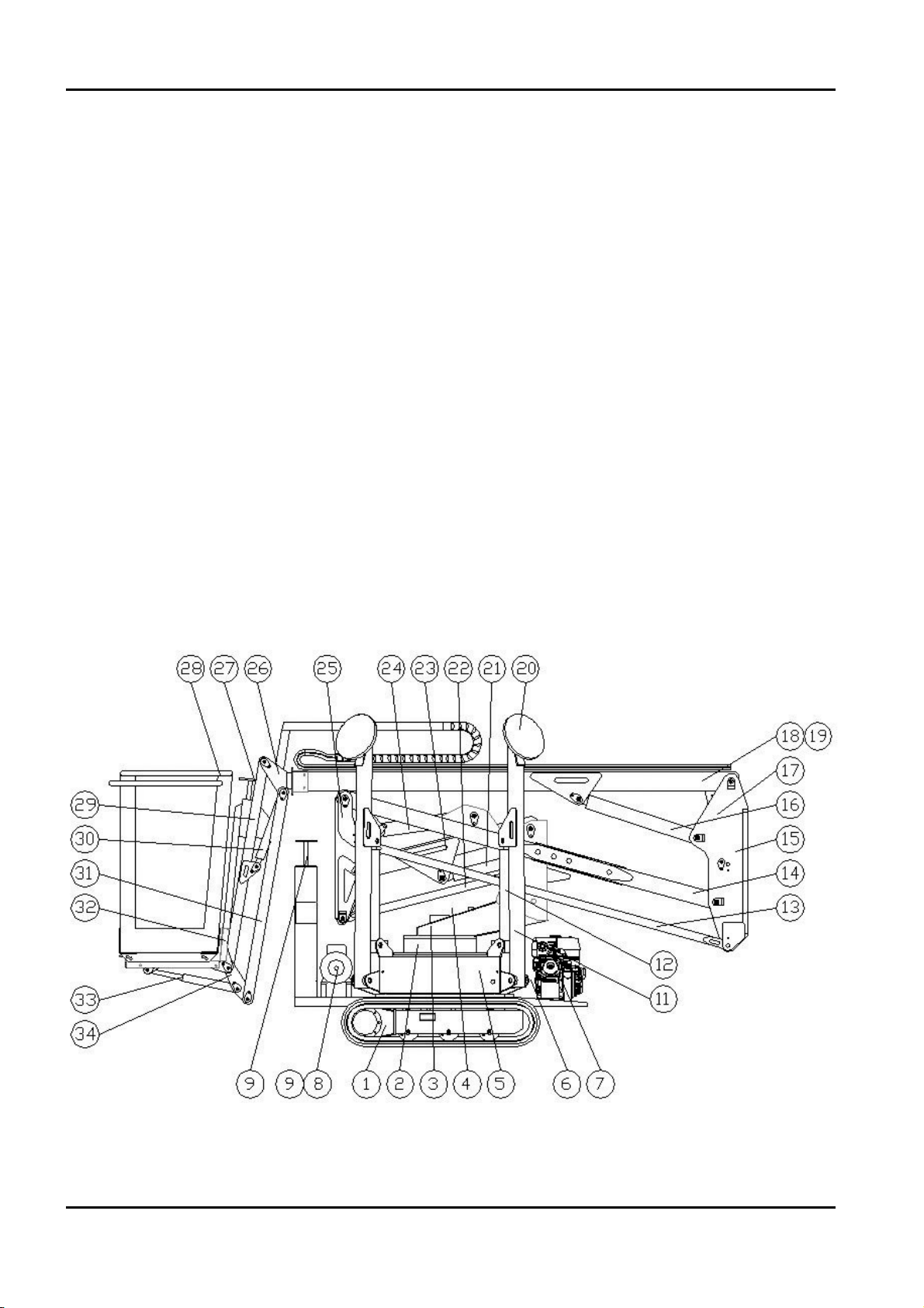
2.1.4 TERMINOLOGY
To make this manual easier to understand, there is a diagram that gives all the exact terms
identifying the different parts of the platform.
BOOM LIFT MODELS X14JH
JLG
12
X14JHR0220311
Page 16

13
2.1.4.1 KEY
1 Extensible rubber crawler
2 Fifth wheel + rotation engine
3 Revolving turret
4 Overhead part emergency controls
5 Base + electric components box + oil tank
6 Triple gear pump
7 Diesel/petrol engine
8 Electric engine
9 Triple gear pump
10 Translation and stabilisers controls
11 Stabilizer
12 Stabilizer cylinder
13 Second arm tie‑rod
14 Second arm
15 Second transmission
16 Third arm cylinder
17 Basket levelling cylinder on transmission
18 Third arm
19 Extraction cylinder
20 Stabilizer cap
21 First arm cylinder
22 First arm tie‑ rod
23 First arm
24 Second arm cylinder
25 First transmission
26 Extraction arm
27 Controls
28 Basket or control car
29 Jib arm
30 Jib cylinder
31 Jib tie‑rods
32 Basket support
33 Basket levelling cylinder on jib
34 Jib transmission
BOOM LIFT MODELS X14JH
JLG
X14JHR0220311
Page 17

2.2 GENERAL SAFETY RULES
NOT OBSERVING THE SAFETY PRECAUTIONS LISTED IN THIS SECTION AND
SHOWN ON THE MACHINE CAN CAUSE INJURIES OR DEATH TO THE STAFF AND
DAMAGES TO THE MACHINE AND IS A SERIOUS VIOLATION OF SAFETY RULES.
This section of this INSTRUCTION AND OPERATING MANUAL describes the dangerous
procedures or situations that could cause damages to things and/or people and what the
operator must do to avoid them.
• The operator must always work professionally, observing all the safety rules, taking care
not to underestimate their own responsibility towards themselves and all the things and
people around them.
• Before starting work it is essential that the operator makes sure the safety devices are in
perfect conditions, that they make the necessary checks on the machine and become fami‑
liar with the ground conditions where they must manoeuvre and stabilise.
• When working it is essential that one specialised person with knowledge of the use of the
machine and the contents of this INSTRUCTION AND OPERATING MANUAL stays on
the ground.
• It is absolutely forbidden to do any alterations to the machine without any prior written
authorisation from the Constructor as this could damage its functioning and its safety.
The Constructor declines any responsibility for injury or damage caused by such beha‑
viour.
Clothing and protective wear
Avoid wearing loose clothes, rings, watches or anything that
could get entangled inside the rotating parts.
When operating the machine or doing maintenance jobs,
wear a helmet, safety glasses and safety shoes, gloves and
noise protection earmuffs after checking their integrity.
Wear the homologated and certified safety belt
Before operating at height it is necessary to correctly wear the safety belts and to fasten them
to the anchorages of the basket.
The use of the safety belts is compulsory in connection with the local regulatins of every sin‑
gle State. In those States where the law does not require the use of holding systems, the choi‑
ce is of the employer or/and user.
BOOM LIFT MODELS X14JH
JLG
14
X14JHR0220311
ATTENZIONE
IMPORTANTE
IMPORTANT
WARNING
Page 18
15
Safety valves
Never alter and/or tamper with the safety valves and the controls in the main hydraulic
system. The Constructor declines any responsibility for damages to people, things or the
machine when the hydraulic valve standard gauging has been tampered with.
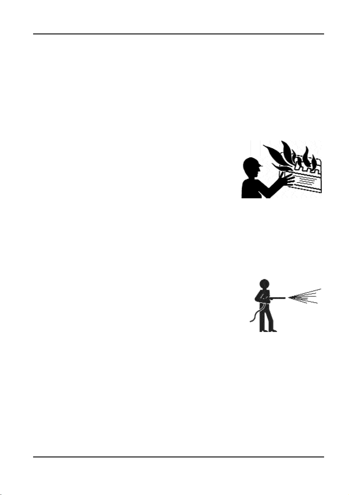
Fire prevention
Keep the engine compartment clean. Remove any pieces of
wood, paper and other flammable products; clean properly
any fuel leaks as they can be potential fire risks.
Petrol is extremely flammable and explosive under certain
conditions. Refuel in a well‑ventilated place and when the
engine is off.
Never smoke or cause sparks in the refuelling place or the fuel
storage place.
After refuelling, make sure that the cap is closed safely and
properly.
Take care not to touch the exhaust pipe when it is hot, as it remains hot during the working
of the machine and also after turning off the engine.
Preventing damages caused by washing the machine
When washing the machine do not direct high‑ pressure jets
onto the electric components. Do not use chemical or petrol
detergents that could cause serious damages to the plastic
components and the paint.
Preventing damages when the machine is at work.
When the machine has been stabilized and starts working, avoid entering in its working
range.
Manoeuvre systematically the controls slowly and regularly. Do not invert movements sharply.
BOOM LIFT MODELS X14JH
JLG
X14JHR0220311
Page 19
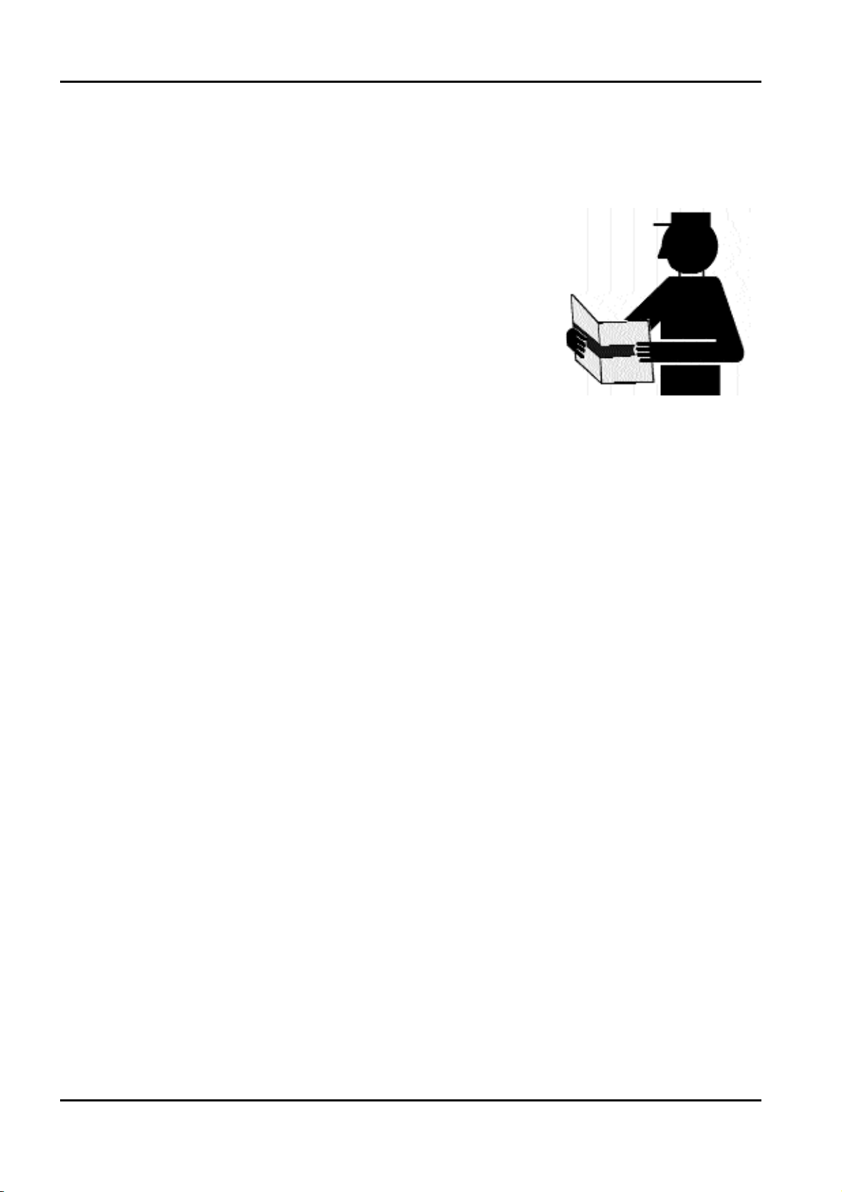
2.3 SAFETY ADVICE
2.3.1 GENERAL ADVICE
To avoid accidents, before starting work and before doing any
operations of maintenance, read, understand and follow all
the warnings and instructions given in this manual. The
machine operator/user cannot be held responsible if they have
not read this manual and learnt how to manoeuvre the machi‑
ne under the supervision of a qualified operator.
Carefully read all the safety warnings in this manual and the
safety signs on your machine.
Keep the safety signs in proper order and replace them when
they are damaged.
Make sure that the new components on the machine have the proper safety signs.
BOOM LIFT MODELS X14JH
JLG
16
X14JHR0220311
Page 20

17
2.3.2 PICTOGRAMS SITUATED ON THE MACHINE
Here we report the positions of the various boards with pictograms on the machine.
BOOM LIFT MODELS X14JH
JLG
X14JHR0220311
62
34
56X56 MM56X56 MM56X56 MM56X56 MM
3637
57
65x41 MM
58
30
65x41 MM
40 40
64
32
53
3
15
19
28
Ed. 03-05-2011
Tav. 01
cod.17065000
46
2929
26
50 51
180X93MM
1717
1212
35
4
1
21
18
57
10
27
ADHESIEKIT - X14J-H
KIT ADHESIVOS - X14J-H
9
54
14
19
SET OF DECALS - X14J-H
KIT COLLANTS - X14J-H
KIT ADESIVI - X14J-HAUFKLEBERSATZ - X14J-H
66
3
19
15
28
38
47
16
48
Page 21

BOOM LIFT MODELS X14JH
JLG
18
X14JHR0220311
5
6
63
65
30
60
11
56
Ed. 03-05-2011
2
66
50
51
65x41 MM
25
13
55
56X56 MM56X56 MM56X56 MM56X56 MM
Tav. 0 2
cod.17065000
65x41 MM
31
3
60
19
65
15
28
ADHESIEKIT - X14J-H
KIT ADHESIVOS - X14J-H
17
43
1212
23
21
26
37
2929
180X93MM
1
4
8
33
45
25
45
KIT ADESIVI - X14J-HAUFKLEBERSATZ - X14J-H
KIT COLLANTS - X14J-H
SET OF DECALS - X14J-H
17
19
30
60
28
38
48
47
3
15
14
19
16
Page 22

19
BOOM LIFT MODELS X14JH
JLG
X14JHR0220311
Pos. Code Q.ty
01 07060500 02
02 06924300 01
03 1603940004 04
04 1603940005 02
05 07059200 01
06 06555300 01
07
08 1603940015 01
09 1603940016 01
10 1603940017 01
11 06039500 01
12 06039600 08
13 06039700 01
14 06086700 02
15 06039900 04
16 06040000 02
17 06040100 08
18 06040200 01
19 06040300 06
20
21 06040500 02
22
23 1702155 01
24
25 06040900 02
26 1703814 02
27 1701504 01
28 06041200 04
29 06041300 04
30 06561200 03
31 06041500 01
32 1701505 01
32 1701542 01
33 06041800 01
33 07034200 01
34 06041900 01
35 06042000 01
36 06042100 01
37 07060600 02
38 1704277 02
39
Pos. Code Q.ty
40 06044000 04
41
42
43 06056300 01
44
45 07056600 02
46 07064500 01
47 06448200 02
48 06448100 02
49
50 07056700 02
51 1701499 02
52
53 06232100 01
54 06165000 01
55 1603940025 01
56 1603940013 01
57 1706898 02
58 06068600 01
59
60 1001125483 03
61
62 1706493 01
63 1705828 01
64 1706098 01
65 07050700 02
66 07060900 02
Page 23

LANGUAGE STICKERS
BOOM LIFT MODELS X14JH
JLG
20
X14JHR0220311
Pos. Code Q.ty
170650IT
06 06555300 01
30 06561200 04
45 07056600 02
46 07064500 01
47 06448200 02
48 06448100 02
55 1603940025 01
170650GB
06 06562600 01
30 06561200 04
30 06042400 04
30 not install 04
47 06462700 02
48 06462100 02
55 1603940026 01
170650FR
06 06562700 01
30 06561200 04
47 06462800 02
48 06462200 02
55 1603940019 01
170650DE
06 06562800 01
30 06561200 04
47 06462900 02
48 06462300 02
55 1603940024 01
170650ES
06 06562900 01
30 06561200 04
47 06463000 02
48 06462400 02
55 1603940027 01
Pos. Code Q.ty
170650NL
06 06563000 01
30 06561200 04
47 06463100 02
48 06462500 02
55 1603940014 01
170650PT
06 06563100 01
30 06561200 04
47 06463200 02
48 06462600 02
55 1603940028 01
Page 24

21
BOOM LIFT MODELS X14JH
JLG
X14JHR0220311
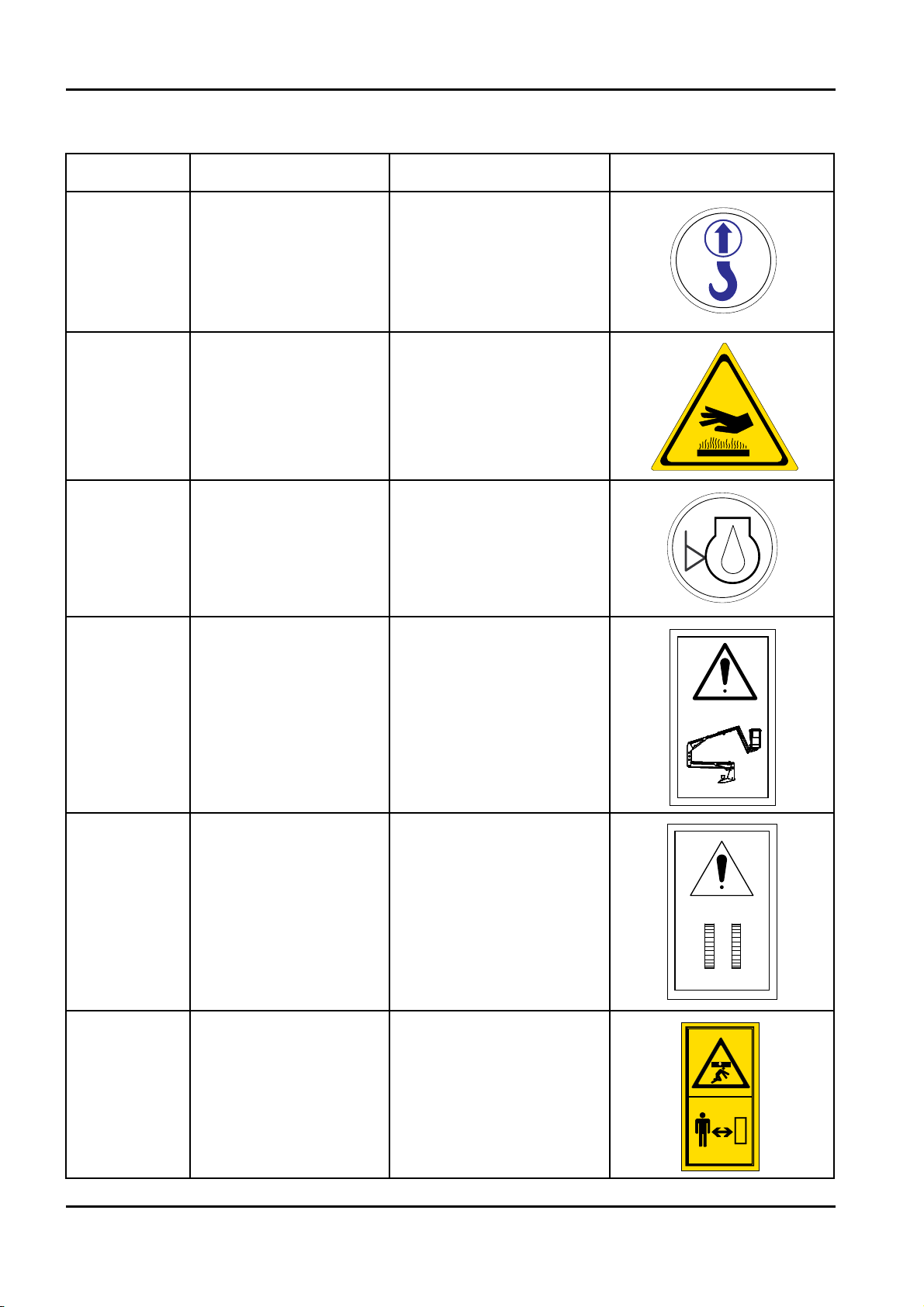
Code Name Description Identikit
06040300
WARNING KEEP SAFE
DISTANCE
06040500
SENSE OF MOVING
UNDERCARRIAGE
DEFINED AS THE
DIRECTION FORWARD
06040800
CRUSHING HAZARD
PERSON
06040900
OBLIGATION TO
READ THE MANUAL
BEFORE USE OF
MACHINE
1703814
FIXING POINT FOR
TRANSPORT
INDICATES CORRECT
FIXING POINT FOR
TRANSPORT OF THE
MACHINE
06041200
CRUSHING HAZARD
FEET
INDICATES AREAS
WHERE THERE IS A
DANGER OF CRUSHING
LOWER LIMBS FOR THE
OPERATOR
06041300
CRUSHING HAZARD
PERSON
INDICATES AREAS
WHERE THERE IS A
DANGER OF CRUSHING
UPPER LIMBS FOR THE
OPERATOR
06040300
06040500
06040800
06040900
1703814A
06041200
06041300
Page 25
BOOM LIFT MODELS X14JH
JLG
22
X14JHR0220311
Code Name Description Identikit
06044000 LIFTING POINT
INDICATES CORRECT
LIFTING POINTS FOR
LIFT THE MACHINE
06056300
DANGER HIGHT
TEMPERATURE
06060000 ENGINE OIL LEVEL
06085900
EMERGENCY DEVICE
FOR AERIAL PART
DEVICE THAT ALLOWS
TO EXCLUDE THE
SAFETY OF THE
AEREAL PART IN CASE
OF EMERGENCY OPE‑
RATIONS
06086000
EMERGENCY DEVICE
FOR UNDERCARRIA‑
GE
DEVICE THAT ALLOWS
TO EXCLUDE THE
SAFETY OF THE
UNDERCARRIAGE IN
CASE OF EMERGENCY
OPERATIONS
06086600
WARNING KEEP SAFE
DISTANCE AND CRU‑
SHING HAZARD PER‑
SON
0
6
0
4
4
0
0
0
06056300
0
0
0
0
6
0
6
0
06085900
06086000
06086600
Page 26
23
BOOM LIFT MODELS X14JH
JLG
X14JHR0220311
Code Name Description Identikit
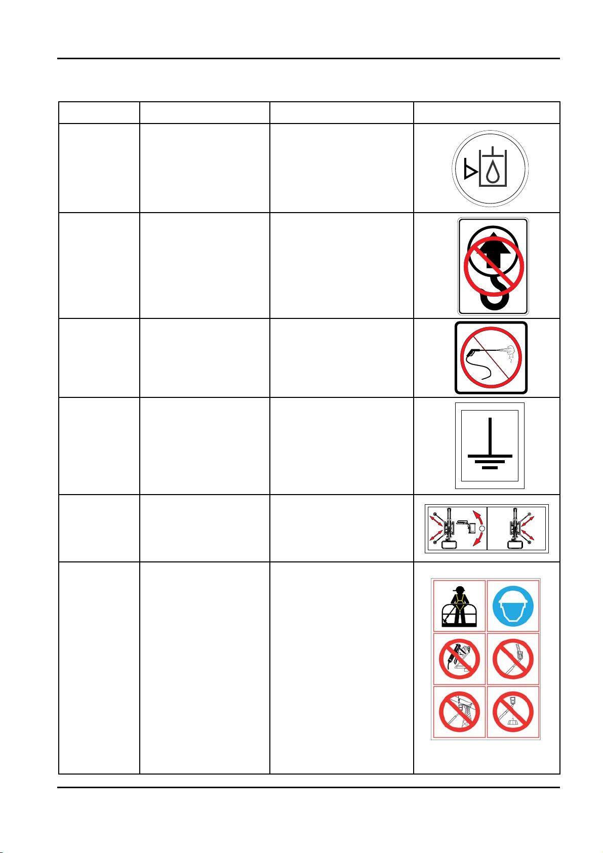
06165000
HYDRAULIC OIL
LEVEL
1701499
FORBIDDEN LIFTING
POINT
1001125483
DO NOT WASH WITH
WATER
06560500 GROUNDING
06040200
HAND PUMP
LEGEND
QUICK INSTRUCTIONS
FOR USING THE EMER‑
GENCY HAND PUMP
06924300
BE CAREFULL AT
WORK
USING SAFETY HAR‑
NESSES, USE PROTECTI‑
VE EQUIPMENT (HEL‑
MET), PROHIBITION OF
WELD ON THE MACHI‑
NE, PROHIBITION OF
USE SYSTEMS TO
INCREASE THE AREA
OF WORK INSIDE THE
BASKET , PROHIBITION
OF WORKING IN THE
VICINITY OF VOLTAGE
ELECTRIC, PROHIBI‑
TION OF USE OF THE
PLATFORM FOR RAI‑
SING LOADS
1701499
1001125483
0
0
0
5
6
1
6
0
06560500
06040200
0692430006924300
Page 27

REPLACE ALL STICKERS AND PLATES AS SOON AS THEY GET WORN.
NOT OBSERVING INSTRUCTIONS REGARDING WEAR AND TEAR, LOST OR NOT
CONSULTING A SAFETY STICKER CAN CAUSE SERIOUS ACCIDENTS.
BOOM LIFT MODELS X14JH
JLG
24
X14JHR0220311
Page 28

25
2.3.3 NOISE AND VIBRATIONS
JLG platforms with thermic engine have been field‑tested according to the parameters of the
European Regulations 2000/14 CE and have registered a guaranteed 97dB (A) acoustic pres‑
sure level.
During overhead operations, this figure decreases as the control car moves away from the
main source of noise.
The vibrations figures transmitted to the operator both through the controls and directly
from the control car floor were assessed as lower than the maximum authorised limits.
2.4 INSTRUMENTS AND CONTROLS
You will find below the indication for all the control functions and the indicators on the
platform. Each device has a sticker nearby which describes briefly its applied function, but
there are very often symbols used for encouraging a quick and safe use. Before operating the
platform, read the description below to understand further the functions of each device and
possibly learn the manufacturer’s advice.
Before starting operating the platform the operator must read and understand perfectly the
instructions given in this manual.
2.4.1 BASKET CONTROL DEVICE
2.4.1.1 B
ASKET ELECTRIC PANEL
BOOM LIFT MODELS X14JH
JLG
X14JHR0220311
Page 29

BOOM LIFT MODELS X14JH
JLG
26
X14JHR0220311
REF. DESCRIPTIONS PICTOGRAMS NEAR THE
CONTROL
1 Starter pushbutton
2
Engine starting pushbutton
It allows a selected start of the engine by means
of selector 4 directly from the control place on the
control car.
3
Work selector
For the machine, you can select two working methods by
using the jib or not.
Without the jib method the maximum admitted
load on the control car is 200 kg (2 x 80 kg people + 40kg
equipment) in std two‑seater basket.
Using the jib method the maximum admitted load on
the control car is 120 kg (1 x 80kg person + 80kg equip‑
ment).
4
Engine type and emergency descent selector
This selector allows to choose either electric or
petrol/diesel engine or, in case of emergency to excite, for
emergency descent, the solenoid valves situated on the
cylinders on the first, second and third arm descending
the frame overhead part through gravity. The particular
construction of this selector forces the operator, in case of
emergency descent, to keep it continuously rotating,
otherwise the selector would go back automatically to
the pre‑selected position.
5
Emergency stop pushbutton
It allows stopping all the machine functions.
Turn the pushbutton to make the machine operative.
6
PLC feeding pilot light
This green light indicates voltage in the electric system of
the machine and therefore in the PLC which controls all
its functions.
THERMIC ENGINE
ELECTRIC ENGINE
EMERGENCY DESCENT
Page 30

27
BOOM LIFT MODELS X14JH
JLG
X14JHR0220311
REF. DESCRIPTIONS PICTOGRAMS NEAR THE
CONTROL
7
Load cell pilot light.
This red light indicates that the maximum admitted load
on the platform control car has been exceeded.
On the machine the light comes on when:
‑ you exceed 120 kg on the control car and the jib method
has been selected with selector 4.
‑ you exceed 200 kg on the control car and no jib method
has been selected with selector 4.
When the light comes on, it is accompanied by an inter‑
mittent alarm.
8
Machine closed pilot light
This red light indicates that the overhead part of the
machine frame has been completely lowered and aligned
with the base and that the withdrawing has completely
happened. When this light comes on, the stabiliser
controls and the crawler movements have been enabled.
Two golden arrows, situated near the hydraulic controls
on the crawler, visually signal the machine alignment.
9
Stabilised machine pilot light
This green light indicates that the stabiliser cylinders are
completely opened and therefore all the stabilisers are
resting on the ground.
Once the machine is stabilised the controls for moving
the overhead part of the frame and rotating the fifth
wheel are enabled.
The operator must make sure that the machine is
stabilised without the 1° maximum limit admitted by
the manufacturer.
10
Second speed button (optional)
If pressed and kept in position during the machine’s
translation it controls the switching of the second speed.
Page 31

2.4.1.2 BASKET HYDRAULIC CONTROLS
BOOM LIFT MODELS X14JH
JLG
28
X14JHR0220311
REF. DESCRIPTION OPERATION/
MOVEMENT
PICTOGRAM NEAR THE
CONTROL
1 Basket levelling control
This lever allows acting on the levelling
cylinder of the control car to adjust any
misalignments due to possible anomalies
in the system.
Being an emergency device and a dange‑
rous manoeuvre, the operator must use a
tool (e.g. screwdriver) to activate the
distributor.
Lever forward:
basket rotating
toward the machine
Lever backward:
basket rotating away
from the machine
2 Lever controlling movement of third arm
This lever allows the operator to raise or
lower the platform third arm.
Lever forward:
raising third arm
Lever backward:
lowering third arm
3 Lever controlling first and second arm
This lever allows the operator to raise and
lower the first and second arm of the
platform. The synchronisation of the
movement between the first and the
second arm allows to always have the
maximum range when working and can
be obtained thanks the particular configu‑
ration of the system and does not depend
on the operator.
lever forward:
synchronised raising
of the first and
second arm
lever backward:
synchronised lowe‑
ring of the first and
second arm
4 Jib control lever
This lever allows the operator to raise and
lower the jib.
lever forward:
raising jib arm
lever backward:
lowering jib arm
Page 32

29
BOOM LIFT MODELS X14JH
JLG
X14JHR0220311
REF. DESCRIPTION OPERATION/
MOVEMENT
PICTOGRAM NEAR THE
CONTROL
5 Withdrawal control lever
This lever allows the operator to extract
and insert back the arm.
lever forward:
re‑entry withdrawal
toward the machine.
lever backward:
withdrawal towards
the outside
6 Rotation lever
This lever allows the operator to rotate
the overhead part of the platform frame
around the fifth wheel axis.
The machine alignment is indicated in
paragraph 2.4.1.1
lever forward:
anticlockwise rota‑
tion of the overhead
part
lever backward:
clockwise rotation of
the overhead part
Page 33

2.4.1.4 CRAWLER HYDRAULIC CONTROLS
The controls for translating and stabilising the machine have been designed to be operated
from the basket. This way the operator is protected from any risks caused by contact with the
rubber tracks and the stabilisers and they are able to see clearly the levelling indicator for
stabilising the control car.
When controlling the translation of the machine from the control car, take the maximum care
to elements like cornices, terraces, lintels, branches etc. that could come into contact with the
operator.
If the machine translation is controlled from the ground (see par.2.1), remember that the
machine must be orientated with the part of the control car toward the back so that, in case
of a wrong manoeuvre, the operator does not come into contact with the rubber tracks.
It is absolutely forbidden to do manoeuvres different from those mentioned above, by con‑
trolling translation from the ground as a possible sharp movement of the machine could
crush the operator between itself and the elements present on the manoeuvring area or could
make the operator come into contact with the platform rubber tracks.
BOOM LIFT MODELS X14JH
JLG
30
X14JHR0220311
WARNING
WARNING
WARNING
ATTENZIONE
ATTENZIONE
ATTENZIONE
Page 34

31
BOOM LIFT MODELS X14JH
JLG
X14JHR0220311
REF. DESCRIPTION OPERATION/
MOVEMENT
PICTOGRAM NEAR THE
CONTROL
1 Track widening lever
This lever allows the operator to
increase the width of the rubber
crawler to increase the stability of
the machine in particular on une
ven and soft ground.
By putting the width back into
shape you can obtain a narrower
machine able to enter narrow places.
lever forward:
track widening
lever backward:
track narrowing
2 Lever controlling left rear stabiliser
This lever allows the operator to raise
and lower the left rear stabiliser.
lever forward:
raising left rear stabi‑
liser
lever backward:
lowering left rear sta‑
biliser
3 Lever controlling left front stabiliser
This lever allows the operator to raise and
lower the left front stabiliser
lever forward:
raising left front sta‑
biliser
lever backward:
lowering left front
stabiliser
4 Lever controlling left track movement
This lever allows the operator to move the
track back and forward
lever forward:
moving forward left
track
lever backward:
moving backward
left track
Page 35

ATTENTION!
Only use the acceleration lever located on the hydraulic control panel on the undercarriage,
and not the lever located on the engine as indicated in the picture.
BOOM LIFT MODELS X14JH
JLG
32
X14JHR0220311
REF. DESCRIPTION OPERATION/
MOVEMENT
PICTOGRAM NEAR THE
CONTROL
5 Lever controlling right track movement
This lever allows the operator to move the
right track forward or backward.
lever forward:
moving right track
forward
lever backward:
moving right track
backward
6 Lever controlling the right front stabiliser
This lever allows the operator to raise or
lower the right front stabiliser.
lever forward:
raising right front
stabiliser
lever backward:
lowering right front
stabiliser
7 Lever controlling right rear stabiliser
This lever allows the operator to raise or
lower the right front stabiliser
lever forward:
raising right rear sta‑
biliser
lever backward:
lowering right rear
stabiliser
8 Accelerator lever
This lever allows the operator to accelera‑
te the diesel/petrol engine
lever forward:
accelerating
lever backward:
decelerating
YES
NO
Page 36

33
2.4.1.5 GROUND EMERGENCY CONTROLS SITUATED ON THE REVOLVING TURRET
These controls have been designed to manoeuvre the overhead part of the control car from
the ground only in case of emergency after putting on the proper switch.
BOOM LIFT MODELS X14JH
JLG
X14JHR0220311
REF. DESCRIPTION OPERATION/
/
MOVEMENT
PICTOGRAM NEAR THE
CONTROL
1 Rotation lever
This lever allows the operator to rotate
the overhead part of the platform structu‑
re around the axis of the fifth wheel
The machine alignment is indicated in
paragraph 2.4.1.1
lever forward:
rotating anticlockwi‑
se the overhead part
lever forward:
rotating clockwise
the overhead part
2 Lever controlling first and second arm
This lever allows the operator to raise and
lower the first and second arm of the
platform. The synchronisation of the
movement between the first and second
arm allows having the maximum working
range and this is obtained thanks to the
particular configuration of the system and
does not depend on the operator.
lever forward:
synchronised raising
first and second arm
lever backward:
synchronised lowe‑
ring of the first and
second arm
Page 37

BOOM LIFT MODELS X14JH
JLG
34
X14JHR0220311
REF. DESCRIPTION OPERATION/
/
MOVEMENT
PICTOGRAM NEAR THE
CONTROL
3 Lever controlling third arm movement
This lever allows the operator to raise or
lower the platform third arm.
lever forward:
raising third arm
lever backward:
lowering third arm
4 Withdrawing lever control
This lever allows the operator to pull out
and reenter the withdrawing arm
lever forward:
pulling out toward
the outside
lever backward:
re‑entering toward
the machine
Page 38

35
2.5 SAFETY DEVICES
The instructions reported below regarding the safety devices are given to the user in order to
understand the machine behaviour and the possible working sequences; it will also be possi‑
ble to identify possible breakdowns and to be able to give more detailed information to the
customer service and thus obtaining quicker and cheaper interventions.
The machine is equipped with safety devices able to prevent dangerous situations for the
operator. Before starting any operation, the operator should check the perfect working of
these devices.
If a safety device does not work, either due to a breakdown or tampering, this could cause
serious damage to the machine and could jeopardise the operator’s life. The Constructor has
designed the machine and the safety devices to guarantee the maximum to its customers.
Anyhow the devices must be checked periodically according what described in this manual
and must never be tampered with.
Never intervene, on one’s initiative, on the safety devices. In case of tampering, the manufac‑
turer declines any responsibly regarding possible accidents resulting from such interven‑
tions.
It is absolutely forbidden to tamper with the lead seal or the calibration of the maximum val‑
ves. In case of tampering, the manufacturer declines any responsibility for any possible acci‑
dents resulting from such interventions.
The Constructor declines any responsibility for any damages caused by the machine to
things and/or people if the above mentioned has not been observed.
BOOM LIFT MODELS X14JH
JLG
X14JHR0220311
IMPORTANTE
DANGER
DANGER
DANGER
IMPORTANT
IMPORTANT
PERICOLO
PERICOLO
PERICOLO
IMPORTANTE
Page 39

2.5.1 BATTERY CUTOUT
This device situated on the right side of the electric components box cuts the electric circuit of the
machine locking all its movements. It can be seen easily and is of easy access without any tools. It
must be put on every time you leave the machine at the end of a work shift or for longer periods.
By turning the key clockwise you cut the electric circuit of the machine. By turning the key anti‑
clockwise you cut the electric circuit of the machine and you can remove the key.
2.5.2 DISTRIBUTOR OVERPRESSURE VALVES
All the distributors on the platform are equipped with an overpressure valve that limits the
pressure reached inside the system to the calibration pressure of the valve itself. These valves
are calibrated by qualified people, when testing the platform and they must never be tampe‑
red with.
BOOM LIFT MODELS X14JH
JLG
36
X14JHR0220311
Page 40

37
2.5.3 CYLINDER STOP VALVES
The stabiliser cylinders are equipped with a double stop valve that, in case of breakdown of
the system or breaking of the tubes, stop the cylinder avoiding dangerous situations of
platform instability.
All the cylinders that move the overhead part of the platform structure are equipped with
stop valves that, in case of breakdown of the system or breakage of the tubes, stop the cylin‑
der avoiding that the control car drops through gravity.
Qualified people calibrate these valves when testing the platform and they must never be
tampered with.
2.5.4 PHOTOCELLS AND SWITCH ALIGNMENT OVERHEAD PART OF THE STRUC‑
TURE AND MACHINE BASE
The machine is provided with a double safety photocell which controls that the aerial part of
the structure of the machine is completely lowered and aligned with the base and that the
telescopic arm is completely retracted.
If one of these conditions does not occur, a signal is given to a switch that deactivates the
translation and the stabiliser movement and feeds the overhead part of the structure.
BOOM LIFT MODELS X14JH
JLG
X14JHR0220311
Page 41

2.5.5 ENABLING DEVICE OF THE STRUCTURE OVERHEAD PART
When all the stabilisers are properly placed on the ground, the stabiliser cylinder goes
towards the end of course releasing the micro‑switches situated at the end of the rods. The
micro‑switches send a signal to a solenoid valve that sends oil coming from the carry‑over
device to the controls for the movement of the overhead part of the structure. If for any rea‑
son a micro‑switch should reactivate during the movement of the basket (for example the
raising of a stabiliser or the sinking of the ground) all the movements of the overhead part of
the machine would be inhibited.
2.5.6 SENSOR OF CONTROL CAR LOAD
The load sensor present on the basket made up of a two‑shaft basket support that allows
exclusively vertical movement of the basket. Basket support is supplied by the load cell itself.
Two extensometers are positioned inside the sensor positioned under the basket, which swit‑
ch the relative weight inside the basket to an electric signal. The electric signal is sent to a
card (see photo) that elaborates it and identifies any dangerous conditions.
The maximum load depends on the work modality selected (par. 2.4.1.1 point 3). If the work
mode with jib has been selected, the load equals 120 kg. For the work mode with jib closed
jib the max. accepted load is 200 kg.
When the max. accepted load is reached, a flashing red light appears on the electric control
board as well as an acoustic signal and all platform movement is obstructed.
To restore platform functioning it is necessary to remove excess weight so as to fall within
the max. accepted weight.
BOOM LIFT MODELS X14JH
JLG
38
X14JHR0220311
Page 42

39
• Another alarm is triggered off, obstucting any aerial movement, in case, for any reason, the
basket is lifted by the loading sensor.
The Constructor recommends the maximum care in the proper keep of the entire safety com‑
ponents and in particular the system of the load sensor on the control car. Always check its
proper working if the basket should hit objects when doing jobs as this could cause problems
to the system (e.g. pruning, painting etc.).
2.5.7 CONTROL GUARDS
The control levers of all the distributors are protected against the
accidental falls of objects from the top and from involuntary acti‑
vating from the operator of special welded protection structures
and plate protections.
2.5.8 THE WATER LEVEL
The water level is situated near the control levers in a well visi‑
ble place from the basket. This is the manufacturer’s established
place to carry out all the translating, stabilising and raising ope‑
rations. The water level must be used to check that when the
platform is working, it is levelled at the maximum 1° admitted
inclination. To reach this, the water level must never be out of
the white zone.
An approximate levelling outside the limits imposed by the manufacturer can be seriously
dangerous and can jeopardise the stability of the platform causing risks, even mortal, to the
operator and the other people operating nearby and on the machine.
Never alter the regulations on the water level; this device has been calibrated by the Con‑
structor during the test prior to the sale. Only technicians having the proper tools and autho‑
rised by the Constructor can intervene on the water level.
BOOM LIFT MODELS X14JH
JLG
X14JHR0220311
IMPORTANTE
DANGER
DANGER
IMPORTANT
PERICOLO
PERICOLO
Page 43

2.5.9 LOCKING PIN SCREWS AND NUTS
All the pins used in the platform have been treated against wear and are provided with wel‑
ded flanges (1) to prevent them from rotating inside their seat.
Some pins are provided with rotation locking screws (2) while others are provided with a
retaining block that is welded on the machine body (3).
The pins located in the most delicate positions have threaded ends and are provided with
self‑locking nuts (4) or self‑locking threaded ring nuts (4) to prevent the structure from colla‑
psing.
The correct tightening of all the pin locking devices must be checked carefully and regularly,
according to the intervals indicated by the machine manufacturer.
Never loosen the pin blocks and check regularly their proper tightening. Even If a pin comes
partially out of its seat, this could cause sudden and uncontrollable movements and also the
lost of stability of the machine and/or the falling of the control car.
2.5.10 FOOTSWITCH
To allow the aerial, undercarriage and stabilization movement
of the machine the footswitch device inside the basket must be
pushed.
2.6 EMERGENCY DEVICES
The emergency instructions reported below regarding the emergency devices are supplied to
the user so that they can understand the behaviour of the machine and the possible working
sequences; it will also be easier to identify them clearer and thus act quickly in case of emer‑
gency.
Before starting any operations, it is important that the operator checks the perfect working
order of the emergency devices.
BOOM LIFT MODELS X14JH
JLG
40
X14JHR0220311
4
1
1
2
3
DANGER
IMPORTANT
PERICOLO
IMPORTANTE
Page 44

41
2.6.1 EMERGENCY STOP PUSHBUTTON
It allows the complete stop of any function of the machine in case of emergency.
There are two devices on the machine for emergency stop. The first one is situated on the
platform crawler near the controls just above the fifth wheel (1), the second one is situated on
the basket and is directly fixed on the electric control panel of the control car (2). When the
device is on, turn the pushbutton to make the machine operative.
It is strongly recommended to follow the rule that forbids operating the platform without
anyone on the ground. In fact, an incidental operation (e.g. the falling of a branch) or volun‑
tary from strangers of the emergency stop pushbutton on the revolving turret would put the
occupants of the basket in the difficult situation of not been able to operate any movements,
except the descent with the emergency descent devices (par.2.4.1.5.).
2.6.2 SWITCH ENABLING EMERGENCY CONTROLS
These devices (1‑3) is a tap that allows the operator on the ground to switch the controls
from the control car to the emergency position situated on the revolving turret (2).
It is strongly recommended to follow the rule that forbids operating the platform without anyone
on the ground. In fact, activating the switch by unqualified people could put the occupants of the
basket in a difficult situation of not been able to operate any movements and to be dependable on
the operating movements from the ground. If this was to happen, activate the emergency push‑
button and ask for help, or use the emergency descent devices (par. 2.9.8).
BOOM LIFT MODELS X14JH
JLG
X14JHR0220311
2
1
IMPORTANTE
2
1
IMPORTANTE
IMPORTANT
IMPORTANT
3
Page 45

To avoid this danger there is a lever locking system by means of a padlock. You are remin‑
ded that the ground staff must always have a padlock key to intervene when needed.
2.6.3 HAND PUMP
The hand pump (2) serves to send the oil under pressure to do the manoeuvres in case of
emergency due to breakdowns of the main hydraulic system.
The hand pump is equipped with a manual switch (1) which allows to select the control of
the two right stabilisers (position 1) or the control of the two left stabilisers and the overhead
part of the structure (position 2).
The stabiliser control is only allowed if there are no anomalies in the electric system and
when the ignition key is ON.
In case of breakdown of the electric system, the overhead ‑
undercarriage change over switch must be manually applied
by using the mechanical switch inside the electrical compo‑
nents opening (see photo).
Always remember to remove the mechanical switch and restore the standard configuration
of the switch as soon as you finish the emergency operations. If there is the mechanical swit‑
ch when doing ordinary working operations this will compromise the safety of the machine,
causing possible dangerous situations.
Manoeuvring the stabilisers in case of emergency is only allowed in case of breakdown
of the machine and requires the closing the stabilisers for road transport.
BOOM LIFT MODELS X14JH
JLG
42
X14JHR0220311
1
2
DANGER
IMPORTANT
IMPORTANTE
PERICOLO
Page 46

43
To control the overhead part of the structure without electric current, always remove the nip‑
ple (3) of the electric valve (4 ) (the outer lead seal automatically breaks by unscrewing and
taking off the cap) and arm it manually pushing and turning the knob (5) underneath, il the
inner lead‑covered cable automatically breaks by reinforcing the electrovalve.
The manoeuvre of the stabilisers can be done through the hand pump by only turning the
ignition key ON and making sure that there is no failure of the electric system.
Remember to put back the solenoid valve knob (5) in the originary position paying attention
to reassemble the protective cap and to restore the double lead seal.
When manoeuvring the platform with the emergency controls you are without any safety
devices. It is therefore necessary and mandatory to act on the controls only to bring back the
basket to the ground and making sure to do these manoeuvres without causing the instabi‑
lity of the working platform.
2.6.4 SOLENOID VALVES FOR EMERGENCY DESCENT
The cylinders of the first, second and third arm are equip‑
ped with solenoid valves for emergency descent (1). Acting
on the emergency descent selector on the electric panel con‑
trols situated on the control car excites this solenoid valves
allowing the descent of the overhead part of the structure
through gravity.
The use of this emergency device is bound to the presence of
voltage in the platform electric system.
Follow the same precautions as reported at point 2.6.3
BOOM LIFT MODELS X14JH
JLG
X14JHR0220311
3
4
5
IMPORTANTE
1
DANGER
IMPORTANT
PERICOLO
Page 47

2.7 SAFETY REGULATIONS TO OBSERVE BEFORE USING THE PLATFORM
2.7.1 DANGER OF ELECTRIC FULMINATION
If the operator uses the machine near electrical lines, they must keep a clear distance. In the
chart below are the relative values for keeping a minimum distance from the electrical lines
according to their voltage.
Keep a safety distance from the distribution lines and electrical installations bearing in mind
the possible arc movements and oscillations of your working platform. Also bear in mind the
electric lines own oscillations.
Before starting operating, inspect the working area, taking note of the overhead electric lines,
of moving machinery like for example bridge cranes or road, railway or building equipment.
BOOM LIFT MODELS X14JH
JLG
44
X14JHR0220311
SAFETY DISTANCE NEAR ELECTRIC LINES
TYPE OF VOLTAGE SAFETY DISTANCE
FROM TO (METRES)
0 V 300 V 5
300 V 50 KV 5
50 KV 200 KV 5
200 KV 350 KV 6,1
350 KV 500 KV 7,6
500 KV 750 KV 10,7
750 KV 1000 KV 13,7
ATTENZIONE
ATTENZIONE
WARNING
WARNING
Page 48

45
2.7.2 DANGER DUE TO BAD WEATHER CONDITIONS
NEVER OPERATE IN BAD WEATHER
Never operate when there are storms, snow, fog and wind exceeding 12m/s. Never start the
machine when the ambient temperature is below –20°C and over +40°C.
In case of unexpected rain, always check that the machine is properly stabilised and that the
ground has a proper consistency before starting work again.
2.7.3 DANGER DUE TO THE WORKING AREA
THE MACHINE CAN EXCLUSIVELY WORK ON COMPACT AND LEVELLED GROUND.
Always check that the ground slope where the platform is positioned does not exceed 10°.
When stabilising, check with the water level near the main controls that the maximum incli‑
nation of the fifth wheel plane with respect to the horizontal line does not exceed 1°.
In running conditions, check if there are no people, holes, juttings, obstacles, rubble or things
that might cover holes.
Before entering high risk areas (petrol refineries, supply‑stations etc…), check its feasibility
with the plant safety staff.
BOOM LIFT MODELS X14JH
JLG
X14JHR0220311
ATTENZIONE
IMPORTANTE
IMPORTANT
WARNING
Page 49

2.8 PROCEDURES FOR A PROPER USE
You will find below the using procedures of JLG platforms. Any use different from what is
specified here, unless previously authorised the Constructor, is absolutely forbidden.
2.8.1 OPERATOR’S RECAPITULATORY TABLE OF SAFETY REGULATIONS
You will find below the recapitulatory table with the general safety regulations that the ope‑
rator must follow carefully before starting operating the platform.
We remind you that there is a sticker showing this table near the controls on the control car,
which can easily be seen from the control place.
• The operating of the platform is only meant for assigned and previously trained staff.
• All the controlling manoeuvres of translation, stabilisation of the machine and move‑
ment of the extensible structures must be done from the control place on the control car.
• Follow carefully all the instructing and operating instructions indicated in the
INSTRUCTING AND OPERATING MANUAL annexed to the machine.
• Never exceed the maximum admitted load indicated on the INSTRUCTING AND OPE‑
RATING MANUAL and on the machine with well visible indications applied on the
control car.
• The operator must wear a helmet and fasten safety belts on proper anchors on the con‑
trol car.
Remember that the safety belts must be checked.
The use of the safety belts is compulsory in connection with the local regulatins of every
single State. In those States where the law does not require the use of holding systems,
the choice is of the employer or/and user.
• Before starting work, the operator must make sure that the safety devices are in perfect
working condition, that the main mechanical parts and the fuel and oil level are in
working order.
• Never operate on sinking, uneven and slippery grounds or with slopes exceeding the
maximum admitted inclination as this could make the platform unstable.
• Level perfectly the machine frame observing the maximum admitted inclination as indi‑
cated in the INSTRUCTING AND OPERATING MANUAL and visible on the water
level.
• Before doing any movement, check that there are no obstacles and no people in the
trajectory on the working area.
• It is forbidden to work within a 5 m distance from the distribution lines and electric
equipment.
• It is forbidden to operate in bad weather conditions unless it is absolutely necessary.
• It is forbidden to anchor cables, ropes or other on the platform.
• It is forbidden to fix ladders, tools or other on the control car to increase the working hei‑
ght.
BOOM LIFT MODELS X14JH
JLG
46
X14JHR0220311
Page 50

47
• Always manoeuvre the controls slowly and regularly without inverting sharply the
movements.
2.8.2 WORKING AREA
BOOM LIFT MODELS X14JH
JLG
X14JHR0220311
200kg MAX. LOAD
(2x80kg people + 40kg
tool box)
120kg MAX. LOAD
(1 x80kg person + 40kg
tool box)
Page 51

2.9 USE OF THE OVERHEAD PLATFORM
When giving the explanations contained in this manual, it is implied that the operator has
read and understood what has already been said in the previous paragraphs in this manual.
There will be therefore fewer repetitions of warnings and photographs than in the previous
parts of the manual.
The Constructor overhead platforms are suitable for doing overhead jobs operating from
inside the control car. The platform must only be used by trained staff who knows the place
and the function of all the controls, tools, indicators, pilot lights and the meaning of the
stickers and indications on the machine.
The operator must have understood the manoeuvring procedures of the platform before ope‑
rating it.
The proper use of the platform foresees, beside the operator (or operators) in the control car,
that there is an experienced ground operator, supervising the machine, ready to intervene in
case of dangerous situations and for any emergency manoeuvres. This implies that the
ground staff must also be properly trained regarding the control functions and the using
procedures and that they have read the manual.
‑ Ignoring even a single safety instruction could cause damages to the operator and/or the
machine.
‑ Place a first aid kit and a fire extinguisher near the working area. Use them according to
current regulations.
‑ Never stay within the platform working range. The area underneath the working field
must be surrounded by a barrier. Anyhow it is forbidden to throw objects from the con‑
trol car or towards it.
‑ It is compulsory to wear close‑fitting clothes and to use safety equippment provided
with all the PPE as foreseen by the risks analysis of every single yard (shoes, helmet,
protective gloves and belts).
‑ When the work is carried out by two or more people, always agree on the correct proce‑
dure to follow before starting. Always inform your working colleagues before starting
operating.
‑ Before starting operating at low temperature, turn on the engine for a few minutes to cir‑
culate the hydraulic oil so that it reaches at least 5°C.
‑ Before doing any manoeuvre and when climbing onto the control car, fasten immedia‑
tely the seat belts to their fixing points. Remember that the safety belts must be checked.
BOOM LIFT MODELS X14JH
JLG
48
X14JHR0220311
IMPORTANTE
IMPORTANTE
IMPORTANTE
IMPORTANT
IMPORTANT
IMPORTANT
Page 52

49
‑ If the stabiliser ground pressure should exceed the ground admitted pressure, increase
the resting surface interposing slabs or a foundation of stable material (e.g. wood)
between the ground and the stabilizer cap.
FOOTSWITCH
To allow the aerial, undercarriage and stabilization movement of the machine the foot‑
switch device inside the basket must be pushed. If you try to move the machine without
the footswitch pushed the movement will be prohibited.
2.9.1 PRELIMINARY CHECKS BEFORE STARTING OPERATING
Do the following every day before starting work:
‑ Check that there are no oil leaks from the machine hydraulic system. In case of leaks do
the necessary repairs and top up the level of hydraulic oil (see paragraph about mainte‑
nance operations). Clean the area with a solvent or a detergent and water under pressu‑
re.
‑ Check that there are no starts of corrosion and that there are no cracks near welding.
‑ Check the integrity and the proper working of the rubber tracks belts (see paragraph
about maintenance operations).
‑ Check that there are no broken, damaged or missing components. Check the proper
tightening of the pin locking screws and nuts or safety ring nuts. Replace, tighten and
adjust according to the platform manufacturer’s instructions before operating the machi‑
ne.
‑ Eliminate debris that could cause fires or breakage taking care to the machine control
area and the area around the diesel/petrol engine.
‑ Clean the handrail, footboards and control levers from any oil residues or debris that
could compromise the execution of the manoeuvres in complete safety putting the ope‑
rator at risk. Check the integrity of the pilot lights and the electric control on the electric
panel situated on the control car.
‑ Check the state of the stickers placed on the machine in a well visible way.
‑ Check that there is enough gasoil/petrol in the fuel tank to avoid any useless stops with
relative emergency descents.
‑ Check the proper working condition of the safety devices.
BOOM LIFT MODELS X14JH
JLG
X14JHR0220311
Page 53

2.9.2 START OF THE PETROL/DIESEL (OPTIONAL) ENGINE
‑ Before starting the engine, you must know and have clear all the procedures of the
machine and the engine as described in this INSTRUCTING AND OPERATING
MANUAL given with the machine and know the meaning of the safety stickers.
‑ Read on the manual the recapitulary table of the operator’s safety regulations and apply
all its prescriptions.
‑ Before starting the engine, make sure that the selector on the electrical control panel on
the control car (Part 4 on fig.3) is positioned on the thermic engine.
‑ Starting the DIESEL engine (optional) can be done from the ground by means of the
ignition key lateral to the engine, or directly from the control place on the basket. In this
case, place the engine ignition key to ON before climbing on the control car using the
proper handrails to reach the control position. Then act on the green pushbutton on the
electrical control panel on the control car (re: part 2 on fig.3).
‑ The start of the PETROL engine can only occur from the ground by means of the engine
ignition key (in this case it is impossible to act on the starter), or directly from the control
place. In this case turn the engine ignition key to ON before climbing onto the control
car using the proper handrails to reach the control position. Then act on the green push‑
button on the control electric panel in the control car (part 2 in fig.3). To control the star‑
ter, press the yellow pushbutton on the control electric panel on the control car (re: part 1
in fig.3).
Before starting the engine, make sure that the accelerator control is in the proper position
(about the minimum). Starting a cold engine at an excessive rpm could cause serious dama‑
ges to the engine itself.
STARTING THE ENGINE MUST ALWAYS HAPPEN WITH ALL LEVERS OF THE CON‑
TROL DISTRIBUTORS IN NEUTRAL.
Always check that there are no foreign elements (e.g. branches) activating accidentally a con‑
trol. This might move the platform suddenly independently from the operator’s will and
cause damages to things and/or people.
BOOM LIFT MODELS X14JH
JLG
50
X14JHR0220311
IMPORTANTE
ATTENZIONE
IMPORTANT
WARNING
Page 54

51
2.9.3 START OF THE ELECTRIC ENGINE
‑ Before starting the engine, make sure you know and have clear all the procedures descri‑
bed in the INSTRUCTING AND OPERATING MANUAL of the machine and you know
the meaning of the safety stickers.
‑ Read in the manual the recapitulatory table of the operator’s safety regulations and
apply all its prescriptions.
‑ Feed the machine with an electric cable by means of the clutch situated at the bottom on
the ground control support.
Before this:
‑ Make sure that the features of the electric lines match the voltage and the frequency indi‑
cated on the electric engine plate.
‑ Check the state of the electrical power wire and that its section must be suitable for
2.2kW. To connect use a “3x2.5mm2”three‑pole cable with type F47 earth plate, double
insulation with 16A plug. The maximum length of the cable must be 15 m.
‑ Fit in the ground a ground plate and connect it to the clamp of the machine earth plate,
or check the working order of the connecting net, in case the soil does not allow such
operation (e.g. inside premises).
‑ Before starting the engine, make sure that the selector on the control electric panel on the
control car (re: part.4 in fig.3) is positioned on the electric engine.
‑ Act on the green pushbutton on the control electric panel on the control car (re: part.2 in
fig.3).
THE ENGINE START MUST ALWAYS OCCUR WHEN ALL THE LEVERS OF THE CON‑
TROL DISTRIBUTORS ARE IN NEUTRAL.
Always check that there are no foreign elements (e.g. branches) activating accidentally a con‑
trol. This might move the platform suddenly independently from the operator’s will and
cause damages to things and/or people.
2.9.4 TRANSLATION
The machine is a self propelled machine able to move easily on any type of soils, able to
overcome big slopes (up to 18 degrees) and, seen the contained dimensions, to enter in nar‑
row places.To translate, it is absolutely necessary that the machine is closed and aligned. The
basket is the only control place planned by the manufacturer that prevents the operator from
accidents when doing the operations connected to the translation of the machine. In fact, the
controls have been designed to be used from that place in order to have a good sight of the
involved area.
BOOM LIFT MODELS X14JH
JLG
X14JHR0220311
ATTENZIONE
WARNING
Page 55

The travel function can be controlled from the ground position only when the machine has to
pass pass through reduced‑height or narrow spaces. In these cases, to allow the machine to
access these spaces, the two‑place cage must be removed.
In this case the machine can be moved forward by an operator in the ground position, but
only lengthwise AND ONLY FROM THE RIGHT SIDE AND WITH THE CAGE REMOVED.
In such conditions it is absolutely forbidden to use the 2
nd
travel speed.
Always choose a proper rpm to have a precise control of the movements and also according
to the operating area.
Never climb or get off the basket if it is not completely lowered.
Controlling the travel of the machine from the ground with the cage removed is conside‑
red an extraordinary procedure that should be adopted only when the work area cannot be
reached in any other way.
The standard machines have not been homologated for road circulation. The working areas
and autonomous transfers must be circumscribed and signalled according to current regula‑
tions. For transfers even short ones on public road, the machine must be carried on homolo‑
gated vehicles.
After reinstalling the cage, put back the iron caps immediately.
‑ When controlling the translation of the machine from the control car, take the maximum
care of elements like cornices, terraces, lintels, branches etc. that could come into contact
with the operator.
‑ In case of ground control of the machine (see the a.m. admitted cases), remember that
the machine must have the control car removed.
‑ It is absolutely forbidden to do manoeuvres different from the above mentioned ones by
controlling translation from the ground as a possible sharp movement of the machine
could crush the operator between itself and the elements present on the manoeuvring
area or make the operator come into contact with the rubber tracks or the platform stabi‑
lisers.
‑ You must not translate when the stabilisers are not completely raised and placed in tran‑
sport position.
‑ The second translation speed (optional) can be used only on a straight and levelled sur‑
face on a solid ground.
BOOM LIFT MODELS X14JH
JLG
52
X14JHR0220311
DANGER
DANGER
DANGER
IMPORTANT
PERICOLO
PERICOLO
IMPORTANTE
PERICOLO
Page 56

53
2.9.4.1 PARKING OF THE MACHINE ON A SOLPE OR DISCONNECTED GROUND
When parking the machine on a slope or disconnected ground with the stabilizers closed
make sure to stall the corners with wedges in order to avoid unintentional movements of the
machine.
‑ It is absolutely forbidden translating with the second speed on a non‑levelled or ravel‑
led surface and on curved surfaces.
2.9.5 STABILISING AND LEVELLING THE MACHINE
Once the machine has been placed, proceed with its stabilising and levelling. Above all make
sure that the surfaces where you are can bear the specified ground pressure exercised from
the machine (see technical data paragraph).
‑ Always remember to keep away from escarpments or ditches of the same depth and
keep at the prescribed distance from the electric lines.
‑ Make sure not to hit things or people when lowering the stabilisers.
To proceed with the stabilising and levelling operations, act from the basket on the controls
relative to each stabiliser to lift the crawler from the ground as much as possible; once done
act softly on the control levers of the stabilisers to bring the machine to the best levelling. To
check that such condition has been met, there is a water level on the machine; when the air
bubble is completely inside the green area (see the photo below) the machine is in the condi‑
tion admitted for its use. Remember that the maximum slant the machine can be levelled is
within a 1° tolerance signalled on the water level at 10 degrees. Grounds with higher slopes
do not allow a proper stabilisation and are a serious risk for the users.
On each stabiliser (see photo below), near the cylinder connection to the stabiliser itself, there
is an orange light. This light flashes when the stabiliser is resting on the ground.
BOOM LIFT MODELS X14JH
JLG
X14JHR0220311
DANGER
PERICOLO
Page 57

NOTE: it is important that when the machine is stabilized the undercarriage is ALWAYS lif‑
ted from the ground.
An improper stabilisation of the machine does not allow a proper working stability. The
Constructor forbids the use of the machine if not stabilised as prescribed in this manual. The
turning over of the machine can cause serious injuries or death to its occupants and ground
staff.
If one of the orange lights on each stabiliser does not flash even when the stabiliser is raised
from the ground, stop the machine immediately and call the customer service as this signals
the breakage of the micro‑switches of the relative stabiliser.
If working on the machine stabilised on slippery surfaces (marble, porphyry, smoothed con‑
crete, wet smooth surfaces etc.), check that the basket movements do not induce the moving
of the crawler. In this case, stop the operations and go back to the operating safety conditions
established by the manufacturer.
2.9.6 MOVING THE CONTROL CAR
Once the machine has been correctly stabilized it is possible to proceed with the motion of
the basket:
‑ Climb onto the basket alone with the tools necessary for the operations for an overall
load not exceeding 120kg;
‑ Position properly the machine;
‑ Stabilise the machine within the limits planned by the manufacturer according the pro‑
cedure described in this manual;
‑ Select option 120kg on the electric panel on the control car;
‑ Lift the third arm;
‑ Raise the pantograph composed of 1st and 2nd arm (to do so act on the lever which con‑
trols them automatically);
‑ Lengthen the withdraw;
‑ Lift the jib.
BOOM LIFT MODELS X14JH
JLG
54
X14JHR0220311
IMPORTANTE
DANGER
DANGER
DANGER
IMPORTANT
PERICOLO
PERICOLO
PERICOLO
Page 58

55
Never rotate the platform with the control car completely lowered; to avoid hitting the stabi‑
lisers with lower part of the basket, it is necessary and mandatory to lift it of about 1 metre.
If the machine does not allow the opening of the jib, check the overall load introduced on the
control car as the load sensor has probably sensed a higher load; if it were not the case, the
proper 120kg option has not been selected with the proper control and in this case the machi‑
ne does not allow the movement of the jib. If instead all the conditions have been met, check
the working order of the platform and contact the customer service.
To close the machine, follow these movements:
‑ Lower the jib;
‑ Re‑enter the withdraw;
‑ Close the third arm;
‑ Lower the pantograph;
‑ Bring the arm on the support;
‑ Raise the stabilisers.
• It is absolutely forbidden to carry any types of material on the control car if the
machine has not been stabilised and completely closed. Loading material in the con‑
trol car when it is overhead from for example roofs or balconies etc. can cause the una‑
voidable turning over of the machine exposing the occupants and ground staff to a
probable death risk.
• Never use the machine to carry loads; the machine can carry two people (80kg each)
plus 40 kg tools or in 1470 version using the jib one person (80kg) and 40kg tools.
• When lowering the machine near the column, the potential risk of shearing the arms
is signalled on stickers. Anyhow it is the user’s responsibi‑
lity to make people move away from this area.
Never use the machine to carry objects with a large surface to the force of the wind (e.g. large
signboards) even if there are within the machine load limits.
BOOM LIFT MODELS X14JH
JLG
X14JHR0220311
IMPORTANTE
DANGER
DANGER
IMPORTANT
PERICOLO
PERICOLO
Page 59

2.9.7 MANUAL LEVELLING OF THE CONTROL CAR
The platforms are equipped with an automatic levelling device of the control car; this device
has been designed so that the basket floor remains always parallel to the ground indepen‑
dently from the arm movements of the platforms.
Anyhow, due to causes relative to possible blow‑by, it could be necessary to operate manual‑
ly to bring back the basket to its best position. To regulate do the following:
‑ Bring back the basket into the translation position by resting the third arm on the sup‑
port (only if you discover the problem when you are on the overhead control car);
‑ Loosen the safety screws by loosening first the lock nut (you
need two fixed 13 wrenches for this operation) until you free the
control (see photo);
‑ Raise the safety device against accidental activating of the con‑
trol. Act on it softly until you reach the levelling and also lowe‑
ring the engine rpm;
‑ Release the lever softly until the neutral point and bring back the safety screw into posi‑
tion. Finally tighten the lock nut.
Levelling the control car has been designed:
‑ As an exceptional manoeuvre in case a slight troubleshooting of the automatic levelling.
If the trouble was to repeat itself frequently have the control car checked in an authori‑
sed workshop;
‑ Activating the manual levelling control is only admitted from the control car; otherwise
the operator could suffer serious damages from the contact with the mobile parts of the
machine;
‑ Never do the levelling manoeuvre with aims different from the above‑described ones
(e.g. lifting objets, to increase the working range of the platform etc.). Such a use could
cause serious accidents even mortal.
BOOM LIFT MODELS X14JH
JLG
56
X14JHR0220311
WARNING
ATTENZIONE
Page 60

57
2.9.8 MANOEUVRING THE BASKET EMERGENCY DESCENT
The machine has been planned considering any possible emergency situations such as
mechanical breakdowns, electric breakdowns, the operator’s sudden illness etc.). In these
cases it is possible to intervene on the machine both from the basket and the ground place in
order to bring back the machine to transport configuration or anyhow to bring assistance to
the occupant(s) of the control car. You will find below the intervention procedures.
Remember that it is mandatory to have staff on the ground when the platform is working.
2.9.8.1 ACTIVATING THE BASKET EMERGENCY DESCENT
The emergency descent of the control car can be activated from the control car itself only if
the machine electric system has not be compromised; to proceed do the following:
‑ Press the manual selector;
‑ Act on the arm descent controls used normally until the desired height;
‑ Release the manual selector.
Being a descent through gravity obviously it is not possible to have a rotation movement
from the platform and to re‑enter or withdraw the telescopic arm. Therefore the basket
descents vertically at a distance from the rotation centre that is conditioned by the configura‑
tion the machine had at the moment of emergency.
During the emergency descent, the jib cylinder cannot be activated. Therefore with the arm
completely lowered, the control car comes to be at 1.80m from the ground. In this case, to
bring assistance to the person on the control car you need to use an external tool (e.g. lad‑
der).
BOOM LIFT MODELS X14JH
JLG
X14JHR0220311
IMPORTANTE
IMPORTANTE
IMPORTANT
IMPORTANT
Page 61

2.9.8.2 ACTIVATING THE GROUND EMERGENCY DESCENT WITH THE MACHINE
IN PERFECT WORKING ORDER
This emergency descent is only allowed in case of:
‑ the control car operator is taken ill.
The only aim for using the ground emergency descent is to bring assistance to the operator
(s) on board of the control car and to bring the control car near the ground. Any other use is
forbidden.
To do the emergency descent in the above mentioned conditions operate as below:
a) Shift the distributor switch of the distributor control on the basket to the ground distri‑
butor.
b) Turn the key switch to enable the emergency aerial movements from the ground.
c) Operate the arm movement arms until you bring back the operator on the basket to the
ground.
2.9.8.3 ACTIVATING THE GROUND EMERGENCY DESCENT WITH THE HAND
PUMP IN CASE OF ALL ENERGY SYSTEM BREAKDOWN
This emergency descent is only done in case of:
‑ breakdown of the machine electric system as it is not possible to do the emergency
manoeuvre from the control car;
The only aim for using the ground emergency descent is to compensate a breakdown of the
system and therefore to bring the control car near the ground. Any other use is forbidden.
The ground emergency descent can occur using the hydraulic hand pump (par.2.6.3); To move
the basket, pump the oil manually while using at the same time the ground controls relative
to the arm movements.
Never do manoeuvres different from the above mentioned like withdrawing the telescopic
arm, moving the jib, moving the stabilisers and in general all the manoeuvres that could
make the machine unstable.
BOOM LIFT MODELS X14JH
JLG
58
X14JHR0220311
IMPORTANTE
IMPORTANTE
ATTENZIONE
IMPORTANT
IMPORTANT
WARNING
Page 62

59
To carry out the emergency descent in the above‑ mentioned conditions operate as follow:
Case 1: voltage on rotating the ignition key to ON and with the emergency stop pushbutton deactiva‑
ted:
1. Position the switch on the hand pump in the position matching the arms movement;
2. Shift the distributor selection switch from the distributor control on the basket to the
ground distributor;
3. Turn the key switch to enable the emergency aerial movements from the ground..
4. Act on the hand pump and at the same time operate on the levers of the arms move‑
ments individually to bring the operator on the basket to the ground.
Case 2: no voltage or emergency stop pushbuttons activated:
1. Remove the protection cap from the blue safety solenoid valve near the electric engine,
the lead‑covered cable breaks by unscrewing the cap (par. 2.6.3).
2. Arm the mechanical working of the solenoid valve by pushing and rotating (par.2.6.3)
the golden coloured hand grip near the solenoid valve coil. The leaded wire will break
operating the emergency without the use of tools;
3. Position the switch on the hand pump to the position matching the arm movements;
4. Shift the distributor selection switch from the basket distributor to the ground distribu‑
tor;
5. Act on the hand pump and at the same time operate on the levers of the arm movements
individually until you bring the operator aboard the basket to the ground.
6. Deactivate the emergency, restore the leading and put back the protection nipple (par.
2.6.3).
BOOM LIFT MODELS X14JH
JLG
X14JHR0220311
Page 63

2.9.9 MAIN USES PLANNED FOR THE PLATFORM
You will find below the specific warnings for the most frequent uses of the platform. What
follows is integrative and does not replace the contents of the Instructing and operating
manual.
2.9.9.1 SYSTEMS
A simple but important recommendation is to always check that the parts you intervene on
are not under tension. When in doubt, ask the ground staff to check. Remember also not to
come close to the electric lines keeping at a proper distance from the voltage they carry (see
specifications given in this manual).
2.9.9.2 CLOSED PREMISES
To operate in closed premises, the Constructor recommends to opt as much as possible for
the electric engine; If it is not possible make sure there is a sufficient change of air to avoid
accumulating gases harmful to people’s health.
Always remember that if the light in the working place is not sufficient, you must equip
yourself with extra lighting devices.
2.9.9.3 USING FOR PRUNING
This use requires caution to avoid the lost of the machine stability. Remember that:
‑ if branches or trunks fall on the safety devices of the machine this could cause breakage;
‑ the fall of plant parts could damage the machine;
‑ the fall of plant parts could press the ground emergency pushbutton. In this case you
lose control of the machine and you need to ask the ground staff to intervene;
‑ the pruning tools like chain saws exercise a strong force toward the outside of the basket
edge;
‑ Always check beforehand that the shrub to cut cannot fall on any parts of the platform
or the basket.
2.9.9.4 USE FOR REPAIRS AND MAINTENANCE OF ROOFS AND RAIN PIPES
Always remember that the platform must not be used for transporting material in the air
even if is within the load limits indicated by the manufacturer. The platform is not a lifting
equipment.
Always remember that once the basket has been raised from the frame you must never carry
BOOM LIFT MODELS X14JH
JLG
60
X14JHR0220311
Page 64

61
objects. Remember that no safety device can help you when you are in the air with the over‑
loaded basket, as its emergency descent does not guarantee against turning over. The only
way to be safe is to go back as soon as possible within the admitted load limits for the basket
according to the working configuration by unloading the basket.
2.9.9.5 USE FOR PAINTING, SAND BLASTING AND PLASTERING
This type of use requires a meticulous protection of the delicate parts of the machine like the
rods of the hydraulic cylinders, their gaskets, safety devices, telescopic hydraulic withdraws
and inscriptions on the machine (e.g. manufacturer’s plate, warning stickers, load chart etc.).
If sand gets mixed with the protection grease of the withdraws it becomes an extremely abra‑
sive mixture compromising the quality of the machine movements and its life.
2.9.9.6 USE IN SALTY ENVIRONMENT
If the machine is used in environments with a particular corrosive atmosphere, do more fre‑
quent checks regarding rust and the state of greasing and lubrication of the mobile parts
than the ones recommended by the manufacturer in normal conditions.
Cover the machine every time you are not using it even for short periods to protect it from
salt and sand carried by the wind.
2.10 REMOVAL OF THE BASKET
The basket can only be removed to allow passage through holes measuring 1500 and 790 mm.
IF THE MACHINE DOES NOT HAVE A BASKET, YOU CAN ONLY MOVE THE TRACKS AS DESCRIBED ON
PARAGRAPHS
2.1 AND 2.9.4.
To remove the basket act as follows:
‑ Unscrew the aluminium lids on the two basket mounting trunnions (see photo);
‑ SRemove the basket from above.
Re‑assemble the basket as follows:
‑ Insert the basket into the fixing screws on the basket sup‑
BOOM LIFT MODELS X14JH
JLG
X14JHR0220311
ATTENZIONE
WARNING
Page 65

port, paying attention to allow it to descend as parallel as possible to the basket support;
‑ Screw on the two aluminium lids.
2.11 TRANSPORT SAFETY REGULATIONS
Make sure that the means of transport for the platform has a suitable capacity and that no
part of the platform comes out of the limits prescribed by the Highway Code.
2.11.1 LOADING AND UNLOADING ON RAMPS
The platform has a very high manoeuvrability and stability even when translating. However
we recommend the user to operate carefully even during operations apparently simple.
For example to load on a lorry do the following:
‑ park the lorry or the trailer on a flat surface;
‑ make sure that the ramps and the trailer are strong enough to bear the weight of the
machine and that there are no debris or slippery material;
‑ if the vehicles are not properly equipped put blocks under the ramps;
‑ widen the platform crawler;
‑ place the ramps parallel between each other at a distance equal to the one between the
tracks;
‑ climb onto the ramps proceeding with the machine orientated with the control car
toward the rear part;
‑ near the arrival place, proceed carefully to avoid strong jolts when passing from the
slant plane to the arrival plane;
‑ park the machine so that no parts come out of the outline of the mean of transport.
To get off proceed following the above‑mentioned indications and prescriptions.
BOOM LIFT MODELS X14JH
JLG
62
X14JHR0220311
IMPORTANTE
IMPORTANT
RAMPS
CHOCKS
Page 66

63
During the translating and the changing of slant phases, take care not to damage the safety
devices situated below the basket and near the first withdraw end. If the change of slant was
to be too excessive, change the inclination of the ramps or use longer ramps.
2.11.2 LIFTING THE MACHINE
To lift the machine you need lifting equipment with a proper load according to the distance
and the height you want to lift the platform.
• For the lifting operations necessary for maintenance or loading on means of transport
only use machinery (e.g. cranes, overhead travelling cranes etc.) and loading devices
(e.g. cables, chains, hooks) of proper load and in perfect state of preservation; to check
the machine weight consult the paragraph relative to the platform technical data.
In the photograph below, you can see how and where the platform must be hooked.
• When you lift the machine, it must be in transport configuration (arms completely clo‑
sed and lowered, stabilisers completely raised and crawler widened). If not the machine
would be unbalanced and the lifting dangerous.
• Never lift the machine with an operator on board.
• During the lifting phases make sure that no one is in the operating area and always
avoid transiting the suspended machine over people.
Never lift the machine slinging it differently than the one shown; if for example it was lifted
with one arm hooked exploiting the ground anchoring devices (not planned to bear the
platform weight) or simply passing a sling around any arm elements, this would load force‑
fully the fifth wheel and other elements of the machine for which they have not been plan‑
ned. It is highly probable that this will cause structural damages to the machine.
BOOM LIFT MODELS X14JH
JLG
X14JHR0220311
IMPORTANTE
ATTENZIONE
IMPORTANTE
IMPORTANT
IMPORTANT
WARNING
Page 67

2.11.2.1 HOW AND WHERE TO HOOK THE PLATFORM
To lift the platform, hook it to each support pin of the stabiliser cap as indicated on the pho‑
tograph below.
Always hook all four feet as the machine could become unbalanced. Always use four separa‑
te cables, chains or slings; this way, the breakage or an improper anchoring of a connecting
device would not cause dangerous movements of the load.
2.11.2.2 WHAT TO USE FOR HOOKING THE PLATFORM
The lifting device must be in a good state of preservation and used according to the specifi‑
cations supplied by its manufacturer. As the platform weight is not divided equally on the
four stabilisers, the maximum requested load for each of the four cables, chains or slings
used must be:
no lower than 600 kg and their length not shorter that 2,5 m and identical between each
other.
The width of the slings must not be over 40 mm, the chains must not be over 25 mm, the
cable diameters must not be over 25 mm not to exercise a pressure on the stabiliser cap in an
anomalous direction.
Using cables, chains or slings with lengths lower than 2.5m could cause permanent damages
to the machine stabilisers.
BOOM LIFT MODELS X14JH
JLG
64
X14JHR0220311
DANGER
IMPORTANT
PERICOLO
IMPORTANTE
Page 68

65
2.11.3 TRANSPORT OF THE MACHINE
Once loaded on the trailer, fix the machine with tie‑rods as shown on the photo below.
Check that the dimensions of the machine and the trailer match the prescriptions of the
Highway Code.
3. SPECIFICATIONS FOR GREASING AND LUBRICATING
3.1 SAFETY RULES FOR GREASING AND LUBRICATING
• Errors can be extremely dangerous. Before greasing or doing repairs, read carefully the
instructing and maintenance manual.
• Handle any part with maximum care. Keep hands and fingers away from gaps, gearing
and similar. Always use the approved protective devices, like safety glasses, safety glo‑
ves and shoes.
• Never discard lubricants in the environment but collect and discard such products
according to the current regulations in each country.
• Never do any maintenance operations when the working arm is not completely lowered
and/or the machine is stabilised.
• When intervening on the machine, put a visible sign with “DANGER. Do not move the
machine, ongoing checks” on the ignition panel.
BOOM LIFT MODELS X14JH
JLG
X14JHR0220311
DANGER
PERICOLO
Page 69

3.2 LUBRICATING POINTS
Recommended oils and lubricants chart.
3.3 GREASING POINTS
BOOM LIFT MODELS X14JH
JLG
66
X14JHR0220311
MAKE
HYDRAULIC
OIL
ENGINE OIL
‑15° +40°
TRACTION
REDUCTION
UNIT
GREASE
ESSO
CALTEX
AGIP
I P
NUTO H 46
SIRIUS H 46
OSO H 46
HYDRUS H 46
TD 15 W 40
SIGMA TURBO
15 W 40
TARUS TURBO
15 W 40
EP 150
WRP150
BLASIA 150
MELLANA 150
BEACON2
EP 2
GR MUEP 2
GREP 2
M = ENGINE OIL
T = TRANSMISSION OIL
I = HYDRAULIC OIL
G = GREASE
* according to the shortest
(or one week)*
(or a period of team work)*
Page 70

67
RESPECT THE GREASING INTERVALS IN ORDER TO PROTECT PINS AND CONNECTION PIVOTS FROM
THE WEAR AND TEAR
.
3.3.1 GREASING THE TELESCOPIC ARM
AND CHECKING THE WEAR AND TEAR OF THE SLI‑
DING BLOCKS
• Using a brush, spread grease over the
telescopic arm.
• Check visually the play between the
telescopic arm and the sliding blocks.
• In case the play exceeds 3 mm it is neces‑
sary to operate on the plastic registers,
screwing them to lean on the arm in case
of the upper ones, or to bring them to 1
mm in case of the bottom ones.
Control the support and the correct distance slipping off and closing the arm.
• The possible replacement of the sliding shoes has to be made in an JLG authorized work‑
shop
4. MAINTENANCE OF THE MACHINE
4.1 SAFETY REGULATIONS FOR MAINTENANCE OPERATIONS
• The spare parts must match the technical prescriptions established by The Constructor.
This is guaranteed by the use of original spare parts.
• Errors are extremely dangerous. Before greasing or doing any repairs, read carefully the
instructing and operating manual.
• Handle parts with great care. Do not put hands or fingers between two parts. Wear
homologated safety garments like safety glasses, gloves and shoes.
• Handle each item with maximum care. Keep hands and fingers away from gaps, gearing
and similar. Always use the approved protective devices, like safety glasses, safety glo‑
ves and shoes.
• When working on the electric system, always wear protective gloves and remove any
rings, wristwatches or any other metallic jewels. As a general rule, never clean parts with
BOOM LIFT MODELS X14JH
JLG
X14JHR0220311
IMPORTANTE
ATTENZIONE
IMPORTANT
WARNING
Page 71

petrol.
• The interventions on the auxiliary electric system must exclusively be done by our Assi‑
stance Centre to guarantee the conformity of what prescribed in current legislation (EN
60204 and home legislation).
• Always disconnect the battery before intervening on the electric system.
• The hydraulic tubes must always be laid and fitted in a correct manner.
• Tampering with the hydraulic circuit can represent a serious danger for the use of the
platform.
• Never discard lubricants in the environment but collect and discard such products
according the current regulations in every country.
• Check the vehicle at least once a day or every work shift for any identifiable outer dama‑
ges (corrosion, integrity of the structural parts, welding). Any identified variations
(included the functional behaviour) should be signalled immediately to the person in
charge. Stop and block immediately the vehicle and carry out accurate checks.
• A fluid that leaks under pressure can penetrate the skin. Always release under pressure
before removing the hydraulic tubes and tighten properly the pipefittings before letting
in pressure. Keep hands and body away from small holes and nozzles from which comes
out high‑pressure liquid. Use a piece of cardboard or paper to find leaks.
Heavy parts must be lifted by means of lifting equipment of suitable capacity.
• Never do any maintenance operations when the working arm is not completely lowered
and/or the machine is stabilised.
• When intervening on the machine, put a visible sign with “DANGER. Do not move the
machine, ongoing checks” on the ignition panel.
4.2 PERIODIC GENERAL CONTROL
After the first 2000 hours, it becomes necessary a general control of the machine, at a certifi‑
cated centre, which examines the state of the machine and fills in a form furnished by the
Constructor.
The following controls to this first control have to be carried out every 1000 hours.
For locating the JLG certificated assistance centre, please refer you to your own reseller.
BOOM LIFT MODELS X14JH
JLG
68
X14JHR0220311
IMPORTANTE
IMPORTANT
Page 72

69
4.2.1 PERIODICAL MAINTENANCE TIMES
H
ONDA PETROL ENGINE
* First intervention.
BOOM LIFT MODELS X14JH
JLG
X14JHR0220311
DETAIL
INTERVEN‑
TION
BEFORE
STAR‑
TING.
SECOND
NEED
INTERVAL (HOURS)
PAGE
10 50 100 250 500 1000 2000
AIR FILTER
CLEANING
CONTROL
•
REPLACEMENT
•
ENGINE OIL
LEVEL CON‑
TROL
• •
REPLACEMENT
•* •
ENGINE SUMP
CLEANING
•
FUEL TANK
AND NET
CLEANING
•
HYDRAULIC
OIL
LEVEL CON‑
TROL
• •
REPLACEMENT
•
HYDR. OIL
FILTER
CARTRIDGE
REPLACEMENT
•* •
ARTICULATION
POINTS
GREASING
•* •
BATTERY
ELECTROLYTE
LEVEL CON‑
TROL
• •
REDUCTION
GEAR DRIVES
OIL
LEVEL CON‑
TROL
•
REPLACEMENT
•* •
MACHINE
GENERAL
PERIODIC CON‑
TROL
• •*
EXTENSION SLI‑
DING INNER
RING
WEAR CON‑
TROL
•
REPLACEMENT
•
Page 73

PERKINS DIESEL ENGINE
* First intervention.
BOOM LIFT MODELS X14JH
JLG
70
X14JHR0220311
DETAIL
INTERVEN‑
TION
BEFORE
STAR‑
TING.
SECOND
NEED
INTERVAL (HOURS)
PAGE
10 50 100 250 500 1000 2000
FLAT AIR FIL‑
TER
CLEANING
CONTROL
•
REPLACEMENT
•
ENGINE OIL
LEVEL CON‑
TROL
• •
REPLACEMENT
•* •
ENGINE OIL
FILTER
CLEANING
•
REPLACEMENT
•
FUEL FILTER
CLEANING
•
REPLACEMENT
•
WATER SEPA‑
RATOR
WATER CLEA‑
NING AND
DRAIN
• •
HYDRAULIC
OIL
LEVEL CON‑
TROL
• •
REPLACEMENT
•
HYDRAULIC
OIL FILTER
CARTRIDGE
REPLACEMENT
•* •
ARTICULATION
POINTS
GREASING
•* •
BATTERY
ELECTROLYTE
LEVEL CON‑
TROL
• •
REDUCTION
GEAR DRIVES
OIL
LEVEL CON‑
TROL
•
REPLACEMENT
•* •
MACHINE
GENERAL
PERIODIC CON‑
TROL
• •*
EXTENSION SLI‑
DING INNER
RING
WEAR CON‑
TROL
•
REPLACEMENT
•
Page 74

71
4.3 RUBBER TRACK MAINTENANCE
4.3.1 CHECKING TRACK TENSION
Park the machine on a solid and flat surface. Lift machine safety and put stable blocks under
the crawler frame to support it. Measure distance A from the roller bottom to the rubber
track rigid inner part. The track tension is correct if measurement A is between 10 and 15
mm.
If the track tension is not within the above‑mentioned measurements, not too loose nor too
tight, follow the instructions given in the following paragraph.
4.3.2 OPERATIONS TO LOOSEN OR TIGHTEN TRACK
The grease contained in the hydraulic track is under pressure. Therefore never loosen grea‑
sing valve 1 for more than one turn. If the valve is too loose, it might get expelled under the
grease pressure, exposing the operator to risk. Never loosen grease nipple 2.
Remove any mud or gravel jammed between the sprocket and the track links before loose‑
ning them.
1. Remove screws and plate 3 to have access to regulation.
2. To loosen track, slowly unscrew valve 1 anti clockwise for no more than one turn. One
turn of valve 1 is sufficient to loosen track.
3. If the grease does not start draining, make the track turn slowly.
BOOM LIFT MODELS X14JH
JLG
X14JHR0220311
DANGER
A
2
1
3
PERICOLO
5
2
0
2
0
2
B
H
1
9
Page 75

4. Once the right tension is obtained, turn valve 1 clockwise and then tighten it. Clean any
grease leaks.
5. To stretch a track, put a grease gun inside grease nipple 2 and add grease until the track
deflection is within specifications.
There is something wrong if the track remains stretched once valve 1 has been turned anti‑
clockwise or loose after putting grease in grease nipple 2. In any case, never try to remove
tracks or dismantle the track tension cylinder, as the high pressure of the grease inside the
track is very dangerous.
4.3.3 CHECKING RUBBER TRACKS
The rubber track structure is shown in fig.A. The steel ropes and the metal core are buried in
rubber.
The engraved threads are meant to give stability when moving on soft soil. They are situated
in the lower part of the ground support. The wheel guides, situated inside the track, prevent
the track from coming out of the guide rollers.
Causes of damages
A) Steel ropes breakage
An excessive tension causes the breaking of the steel ropes under the following conditions:
‑ When there is an excess of stones and foreign material between the track and the crawler
frame;
‑ When the track comes out of its guide;
‑ When there is strong friction like quick changes of direction.
BOOM LIFT MODELS X14JH
JLG
72
X14JHR0220311
CARVED PROFILE
WEEL SIDE
METAL CORE
STEEL ROPES
SPROCKET HOLE
DANGER
PERICOLO
SCULTURA
Fig. A
CORDE
D'ACCIAIO
ANIMA METALLICA
FORO RUOTA
DENTATA
LATO RUOTA
Page 76

73
B) Wear and tear of metallic cores
As in the case of the a.m. breakage of steel ropes, an excessive stress might cause the bending
or the breaking of the metallic cores, which can also be caused by the following:
‑ Improper contact between sprocket and track;
‑ Rotation of the inner rollers;
‑ Working in sandy soil.
C) Parting of the metallic cores
The metallic core acts as rubber adhesive between itself and the steel ropes.
Parting can be caused by excessive stress like the
breakage of the ropes, as a result of the following:
‑ The metallic cores have been wound up by the worn
sprocket as shown in the figure.
If the sprocket shows this wear and abrasion, replace it
as soon as possible.
In case of breakage as per paragraphs A‑B‑C‑, it is
necessary to replace the track as this could cause a
complete lost of functionality.
D) Abrasion and fatigue cracks
1. The cracks at the base of the thread are the result of rubber fatigue bending caused by the
sprocket and the track tensioner.
2. The cracks and the curves on the rubber edge are due to
manoeuvring the track where there are concrete kerbs and sharp
edges.
3. The cracks and abrasions on the rubber of the roller guide slides are caused by fatigue due
to the compression of the rubber under the wheel weight combined to working in sandy
soil, or repeated sharp changes of direction.
4. The abrasion of the engraved thread can originate especially in case of rotations on con‑
crete surfaces, gravel or hard surfaces.
The conditions for damage indicated in paragraph D point 1, 2, 3 are not to be considered
deadly for the track and even if there is a gradual or progressive damage, the track will con‑
tinue to work.
If the damage indicated at point 3 worsens, this will expose the metallic cores. If this exposi‑
tion is more than half the track circumference, it is time to replace it. However you can still
use it.
BOOM LIFT MODELS X14JH
JLG
X14JHR0220311
WORN PARTS
PARTI USURATE
CRACK
Page 77

E) Cracks due to external factors
The cracks on the track outer surface (the one in contact with the ground) are very often due
to contacts with gravel, sharp stones, sharp material such as metal plates, nails, glass, which
can cause cuts. From the point of view of rubber property this cannot be avoided although it
depends from working conditions.
The cracks on the circumference outer surface and on the rubber edge come from the contact
the track has with the crawler body or with concrete sharp edges. The crack increases quite
slowly.
Even if it does not look good, the track can still be used in hard working conditions.
4.3.4 REPLACING RUBBER TRACKS
The grease inside the hydraulic track is under pressure. Therefore never loosen grease nipple
valve 1 for more than one turn; otherwise it might be expelled under the pressure of the
grease, putting the operator at risk. Never loosen grease nipple 2.
In case of gravel or mud jammed between the sprocket and the track link, remove them
before loosening.
Removing rubber track
1. Park the machine on a solid and flat surface, lift it and support it safely by means of the
stabilisers.
2. Remove screws and take off plate 3 to have access to regulation.
3. To loosen the track, slowly unscrew valve 1 in an
anti‑clockwise direction for no more than one turn.
One turn of valve 1 is sufficient to loosen the track.
4. If the grease does not start to drain, turn the track
slowly.
5. Insert 3 steel pipes (4) inside the track in the space
between the rollers. Turn the driving wheel backwards
(5) in a way that the steel pipes proceed with the track
BOOM LIFT MODELS X14JH
JLG
74
X14JHR0220311
DANGER
PERICOLO
2
5
2
0
2
0
2
B
H
1
9
1
3
5
5202
0
2B
H1
9
4
6
Page 78

75
and engage on the track‑tensioning wheel. Apply force (6) laterally to allow the track to run
and lift it from the track‑tensioning wheel.
Fitting rubber track
1. Make sure that all the safety conditions are met when the machine is lifted to fit the track.
2. Check that the grease inside the hydraulic cylinder has been removed.
3. Mesh the track links with the sprocket and place the other end of the track on the track
tensioning sprocket.
4. Rotate driving wheel backward (7) pushing the track shoes inside the frame (8).
5. Using a steel tube, position track and rotate driving wheel again.
6. Make sure the track links are properly meshed onto
the sprocket and the track‑tensioning sprocket.
7. Adjust track tension (see paragraph 4.3.2 ‑“Opera‑
tions to loosen/stretch track”).
8. Place rubber crawler on the ground.
4.4 CHECKING BOLTS AND NUTS TIGHTNESS
According to the use of the platform, it is necessary to check all the parts and bolts and nuts
that could become loose.
Pay special attention to the frame parts such as the track tensioning wheels, the translation
gearmotor, the drive wheels and guide rollers. Check them for tightness as per chart beside.
BOOM LIFT MODELS X14JH
JLG
X14JHR0220311
DANGER
PERICOLO
7
5
2
02
0
2B
H
1
9
8
Page 79

BOOM LIFT MODELS X14JH
JLG
76
X14JHR0220311
or Vibra-
TM
131)
TM
K=0.15
Torque
TITE
(Loctite® 262
TM
111 or
or 271
TM
TM
Torque
OR Vibra-TITE
(Loctite® 242
140) K=.18
Torque
K= 0.20
(Dry or Loctite® 263)
SAE GRADE 8 (HEX HD) BOLTS & GRADE 8 NUTS*
or Vibra-
TM
131)
TM
Torque
TITE
(Loctite® 262
TM
111 or
or 271
TM
TM
140)
Torque
OR Vibra-TITE
(Loctite® 242
Values for Zinc Yellow Chromate Fasteners (Ref 4150707)
Torque
Lubricated
(Dry)
SAE GRADE 5 BOLTS & GRADE 2 NUTS
Torque
Clamp Load Clamp Load
Tensile
Stress Area
Size TPI Bolt Dia
In Sq In LB IN-LB [N.m] IN-LB [N.m] IN-LB [N.m] IN-LB [N.m] LB IN-LB [N.m] IN-LB [N.m] IN-LB [N.m]
In Sq In LB FT-LB [N.m] FT-LB [N.m] FT-LB [N.m] FT-LB [N.m] LB FT-LB [N.m] FT-LB [N.m] FT-LB [N.m]
24 0,3125 0,0580 3700 19 26 14 19 21 29 17 23 5220 25 35 25 35 20 25
24 0,3750 0,0878 5600 35 47 25 34 40 54 32 43 7900 50 70 45 60 35 50
20 0,4375 0,1187 7550 55 75 40 54 60 82 50 68 10700 80 110 70 95 60 80
20 0,5000 0,1599 10700 90 122 65 88 100 136 80 108 14400 120 165 110 150 90 120
18 0,5625 0,2030 12950 120 163 90 122 135 184 109 148 18250 170 230 155 210 130 175
18 0,6250 0,2560 16300 170 230 130 176 190 258 153 207 23000 240 325 215 290 180 245
16 0,7500 0,3730 23800 300 407 220 298 330 449 268 363 33600 420 570 380 515 315 430
14 0,8750 0,5090 32400 470 637 350 475 520 707 425 576 45800 670 910 600 815 500 680
12 1,0000 0,6630 42200 700 949 530 719 735 1000 633 858 59700 995 1355 895 1215 745 1015
12 1,1250 0,8560 47500 880 1193 660 895 925 1258 802 1087 77000 1445 1965 1300 1770 1085 1475
12 1,2500 1,0730 59600 1240 1681 920 1247 1300 1768 1118 1516 96600 2015 2740 1810 2460 1510 2055
12 1,3750 1,3150 73000 1680 2278 1260 1708 1750 2380 1506 2042 118100 2705 3680 2435 3310 2030 2760
1 3/8 6 1,3750 1,1550 64100 1460 1979 1100 1491 1525 2074 1322 1792 104000 2385 3245 2145 2915 1785 2430
12 1,5000 1,5800 87700 2200 2983 1640 2224 2300 3128 1974 2676 142200 3555 4835 3200 4350 2665 3625
1 1/2 6 1,5000 1,4050 78000 1940 2630 1460 1979 2025 2754 1755 2379 126500 3165 4305 2845 3870 2370 3225
3. * ASSEMBLY USES HARDENED WASHER
NOTES: 1. THESE TORQUE VALUES DO NOT APPLY TO CADMIUM PLATED FASTENERS
2. ALL TORQUE VALUES ARE STATIC TORQUE MEASURED PER STANDARD AUDIT METHODS TOLERANCE = ±10%
Torque Specs
48 0,1120 0,00661 420 9 1,0 7 0,8
40 0,1380 0,01015 610 18 2,0 13 1,5
36 0,1640 0,01474 940 31 3,5 23 2,6 1320 43 5
32 0,1900 0,02000 1285 49 5,5 36 4 1800 68 8
28 0,2500 0,0364 2320 120 13,5 86 10 135 15 3280 164 19 148 17
4 40 0,1120 0,00604 380 8 0,9 6 0,7
6 32 0,1380 0,00909 580 16 1,8 12 1,4
8 32 0,1640 0,01400 900 30 3,4 22 2,5
10 24 0,1900 0,01750 1120 43 4,8 32 3,5 1580 60 7
1/4 20 0,2500 0,0318 2020 96 10,8 75 9 105 12 2860 143 16 129 15
3/8 16 0,3750 0,0775 4940 30 41 23 31 35 48 28 38 7000 45 60 40 55 35 50
1/2 13 0,5000 0,1419 9050 75 102 55 75 85 116 68 92 12750 105 145 95 130 80 110
5/16 18 0,3125 0,0524 3340 17 23 13 18 19 26 16 22 4720 25 35 20 25 20 25
7/16 14 0,4375 0,1063 6800 50 68 35 47 55 75 45 61 9550 70 95 65 90 50 70
9/16 12 0,5625 0,1820 11600 110 149 80 108 120 163 98 133 16400 155 210 140 190 115 155
5/8 11 0,6250 0,2260 14400 150 203 110 149 165 224 135 183 20350 210 285 190 260 160 220
3/4 10 0,7500 0,3340 21300 260 353 200 285 388 240 325 30100 375 510 340 460 280 380
7/8 9 0,8750 0,4620 29400 430 583 320 434 475 646 386 523 41600 605 825 545 740 455 620
1 8 1,0000 0,6060 38600 640 868 480 651 675 918 579 785 51500 860 1170 770 1045 645 875
1 1/8 7 1,1250 0,7630 42300 800 1085 600 813 840 1142 714 968 68700 1290 1755 1160 1580 965 1310
1 1/4 7 1,2500 0,9690 53800 1120 1518 840 1139 1175 1598 1009 1368 87200 1815 2470 1635 2225 1365 1855
Page 80

77
BOOM LIFT MODELS X14JH
JLG
X14JHR0220311
or Vibra-
TM
Torque
131) K=0.15
TM
TITE
(Loctite® 262
TM
111 or
or 271
TM
TM
Torque
Zinc Yellow Chromate Fasteners (Ref 4150707)*Magni Coating (Ref 4150701)*
K=0.18
140 OR Precoat 85®
OR Vibra-TITE
(Loctite® 242
(Dry)
Torque
K = .20
See Note 4
Clamp Load
or Vibra-
TM
Torque
131) K=0.15
TM
TITE
SOCKET HEAD CAP SCREWS
(Loctite® 262
TM
111 or
or 271
TM
TM
Torque
K=0.16
140 OR Precoat 85®
OR Vibra-TITE
(Loctite® 242
Torque
(Dry) K = .17
See Note 4
Clamp Load
Tensile
Stress Area
In Sq In LB IN-LB [N.m] IN-LB [N.m] IN-LB [N.m] LB IN-LB [N.m] IN-LB [N.m] IN-LB [N.m]
In Sq In LB FT-LB [N.m] FT-LB [N.m] FT-LB [N.m] LB FT-LB [N.m] FT-LB [N.m] FT-LB [N.m]
Size TPI Bolt Dia
48 0,1120 0,00661
4 40 0,1120 0,00604
40 0,1380 0,01015
6 32 0,1380 0,00909
36 0,1640 0,01474
8 32 0,1640 0,01400
32 0,1900 0,02000
10 24 0,1900 0,01750
28 0,2500 0,0364 3280 139 16 131 15 3280 164 19 148 17
24 0,3125 0,0580 5220 25 35 20 25 20 25 5220 25 35 25 35 20 25
24 0,3750 0,0878 7900 40 55 40 55 35 50 7900 50 70 45 60 35 50
20 0,4375 0,1187 10700 65 90 60 80 60 80 10700 80 110 70 95 60 80
20 0,5000 0,1599 14400 100 135 95 130 90 120 14400 120 165 110 150 90 120
18 0,5625 0,2030 18250 145 195 135 185 130 175 18250 170 230 155 210 130 175
18 0,6250 0,2560 23000 205 280 190 260 180 245 23000 240 325 215 290 180 245
16 0,7500 0,3730 33600 355 485 335 455 315 430 33600 420 570 380 515 315 430
14 0,8750 0,5090 45800 570 775 535 730 500 680 45800 670 910 600 815 500 680
12 1,0000 0,6630 59700 845 1150 795 1080 745 1015 59700 995 1355 895 1215 745 1015
12 1,1250 0,8560 77000 1225 1665 1155 1570 1085 1475 77000 1445 1965 1300 1770 1085 1475
12 1,2500 1,0730 96600 1710 2325 1610 2190 1510 2055 96600 2015 2740 1810 2460 1510 2055
12 1,3750 1,3150 118100 2300 3130 2165 2945 2030 2760 118100 2705 3680 2435 3310 2030 2760
12 1,5000 1,5800 142200 3020 4105 2845 3870 2665 3625 142200 3555 4835 3200 4350 2665 3625
1/4 20 0,2500 0,0318 2860 122 14 114 13 2860 143 16 129 15
3/8 16 0,3750 0,0775 7000 35 50 35 50 35 50 7000 45 60 40 55 35 50
5/16 18 0,3125 0,0524 4720 20 25 20 25 20 25 4720 25 35 20 25 20 25
1/2 13 0,5000 0,1419 12750 90 120 85 115 80 110 12750 105 145 95 130 80 110
7/16 14 0,4375 0,1063 9550 60 80 55 75 50 70 9550 70 95 65 90 50 70
9/16 12 0,5625 0,1820 16400 130 175 125 170 115 155 16400 155 210 140 190 115 155
5/8 11 0,6250 0,2260 20350 180 245 170 230 160 220 20350 210 285 190 260 160 220
3/4 10 0,7500 0,3340 30100 320 435 300 280 380 30100 375 510 340 460 280 380
7/8 9 0,8750 0,4620 41600 515 700 485 660 455 620 41600 605 825 545 740 455 620
1 8 1,0000 0,6060 51500 730 995 685 930 645 875 51500 860 1170 775 1055 645 875
1 1/8 7 1,1250 0,7630 68700 1095 1490 1030 1400 965 1310 68700 1290 1755 1160 1580 965 1310
1 1/4 7 1,2500 0,9690 87200 1545 2100 1455 1980 1365 1855 87200 1815 2470 1635 2225 1365 1855
1 3/8 6 1,3750 1,1550 104000 2025 2755 1905 2590 1785 2430 104000 2385 3245 2145 2915 1785 2430
1 1/2 6 1,5000 1,4050 126500 2690 3660 2530 3440 2370 3225 126500 3165 4305 2845 3870 2370 3225
2. ALL TORQUE VALUES ARE STATIC TORQUE MEASURED PER STANDARD AUDIT METHODS TOLERANCE = ±10%
NOTES: 1. THESE TORQUE VALUES DO NOT APPLY TO CADMIUM PLATED FASTENERS
*3. ASSEMBLY USES HARDENED WASHER OR FASTENER IS PLACED AGAINST PLATED STEEL OR RAW ALUMINUM
4. CLAMP LOAD LISTED FOR SHCS IS SAME AS GRADE 8 OR CLASS 10.9 AND DOES NOT REPRESENT FULL STRENGTH CAPABILITY OF SHCS. IF HIGHER LOAD IS REQUIRED, ADDITIONAL TESTING IS REQUIRED.
Torque Specs
Page 81

BOOM LIFT MODELS X14JH
JLG
78
X14JHR0220311
TM
TM
131)
Torque
Torque
Spec #4150701Values for Zinc Yellow Chromate Fasteners (Ref 4150707)
M6 AND ABOVE*
K = .15
(Loctite® 262
OR Vibra-TITE
TM
TM
or 271
K = .16
TM
111 or 140)
242
OR Vibra-TITE
(Lub OR Loctite®
)
TM
263
Torque
K = .17
(Dry or Loctite®
CLASS 12.9 SOCKET HEAD CAP SCREWS
CLASS 10 METRIC NUTS
See Note 4
Clamp Load
OR
131)
TM
TM
Torque
K=0.15
Vibra-TITE
(Loctite® 262
OR
TM
111 or
TM
Torque
140)
or 271
TM
(Lub OR Loctite®
242
Vibra-TITE
)
TM
263
Torque
K = 0.20
(Dry or Loctite®
K= 0.18
CLASS 10.9 METRIC (HEX HEAD) BOLTS
Load
CLASS 12.9 SOCKET HEAD CAP SCREWS M3 - M5*
Clamp
TM
or 271
Torque
TM
(Loctite®
242
TM
Torque
(Loctite® 262
111 or
TM
140)
OR Vibra-
TITE
131)
TM
OR Vibra-
TITE
315 280 235 97,8 265 250 235
97,8
(Lub)
Torque
)
CLASS 8 METRIC NUTS
TM
263
Torque
(Dry or Loctite®
CLASS 8.8 METRIC (HEX HEAD) BOLTS
Load
Clamp
Area
Stress
Tensile
Size PITCH
Sq mm KN [N.m] [N.m] [N.m] [N.m] KN [N.m] [N.m] [N.m] kN [N.m] [N.m] [N.m]
3 0,5 5,03 2,19 1,3 1,0 1,2 1,4 3,13
3.5 0,6 6,78 2,95 2,1 1,6 1,9 2,3 4,22
4 0,7 8,78 3,82 3,1 2,3 2,8 3,4 5,47
5 0,8 14,20 6,18 6,2 4,6 5,6 6,8 8,85
6 1 20,10 8,74 11 7,9 9,4 12 12,5 12,5 13 12 11
7 1 28,90 12,6 18 13 16 19 18,0 25 23 19 18,0 21 20 19
8 1,25 36,60 15,9 26 19 23 28 22,8 37 33 27 22,8 31 29 27
10 1,5 58,00 25,2 50 38 45 55 36,1 70 65 55 36,1 61 58 54
219 164 197 241
18 2,5 192 83,5 301 226 271 331 119,5 430 385 325 119,5 365 345 325
20 2,5 245 106,5 426 320 383 469 152,5 610 550 460 152,5 520 490 460
22 2,5 303 132,0 581 436 523 639 189,0 830 750 625 189,0 705 665 625
24 3 353 153,5 737 553 663 811 222,0 1065 960 800 220,0 900 845 790
27 3 459 199,5 1080 810 970 1130 286,0 1545 1390 1160 286,0 1315 1235 1160
30 3,5 561 244,0 1460 1100 1320 1530 349,5 2095 1885 1575 349,5 1780 1680 1575
33 3,5 694 302,0 1990 1490 1790 2090 432,5 2855 2570 2140 432,5 2425 2285 2140
36 4 817 355,5 2560 1920 2300 2690 509,0 3665 3300 2750 509,0 3115 2930 2750
12 1,75 84,30 36,7 88 66 79 97 52,5 125 115 95 52,5 105 100 95
14 2 115 50,0 140 105 126 154 71,6 200 180 150 71,6 170 160 150
16 2 157 68,3
42 4,5 1120 487,0 4090 3070 3680 4290 698,0 5865 5275 4395 698,0 4985 4690 4395
NOTES: 1. THESE TORQUE VALUES DO NOT APPLY TO CADMIUM PLATED FASTENERS
2. ALL TORQUE VALUES ARE STATIC TORQUE MEASURED PER STANDARD AUDIT METHODS TOLERANCE = ±10%
4. CLAMP LOAD LISTED FOR SHCS IS SAME AS GRADE 8 OR CLASS 10.9 AND DOES NOT REPRESENT FULL STRENGTH CAPABILITY OF SHCS. IF HIGHER LOAD IS REQUIRED, ADDITIONAL TESTING IS REQUIRED.
*3. ASSEMBLY USES HARDENED WASHER OR FASTENER IS PLACED AGAINST PLATED STEEL OR RAW ALUMINUM
Torque Specs
Page 82

79
4.5 CHECKING HYDRAULIC OIL LEVEL
The check is done when the platform (PLE) and the stabilisers are at rest on flat ground.
Check that the oil level is about half the inspection hole A.
If not, top up through filling tap B. See par.3.2 for oil specifications.
4.6 CHECKING LEAKS FROM THE HYDRAULIC SYSTEM
Check visibly all the flexible tubes, the pipefittings and all the other components of the
hydraulic system, for any leaks.
Usually, you can eliminate the leaks on the tubes by tightening properly the pipefittings
You cannot eliminate the leaks in the sealing areas with gaskets (o‑rings, sealing rings etc) by
single tightening as the gasket leaks because it is damaged or hardened.
You can only restore the sealing by replacing the gasket.
4.7 CHECKING FILTER CARTRIDGE
BOOM LIFT MODELS X14JH
JLG
X14JHR0220311
A
B
A
Page 83

Replace the cartridge at each oil replacement and according to the intervals indicated by the
maintenance chart (par.4.2)
NOTE: Always do the first replacement of the cartridge after the first 50 working hours, to
eliminate working residues of tubes and hydraulic components from the hydraulic system.
1. Unscrew cap A and extract the filter cartridge.
2. If the cartridge is very dirty, replace it with a new one with the same features.
3. Tighten cap A.
4.8 CHECKING MACHINE PLATES
‑ Check if the prohibition, warning, danger and control plates are on the machine and that
they are legible.
‑ Consult the pictogram paragraph to identify any missing or damaged plates.
4.9 CHECKING WORKING PRESSURES OF THE HYDRAULIC SYSTEM
To do this check, use a pressure gauge with a 200 bar minimum at the bottom of the scale.
‑ Make sure the machine is closed and at rest.
‑ Make sure that no one is within the machine working range.
‑ All the controls must be made as defined in this manual from the driver’s place on the
basket.
a) Connect the pressure gauge to the pressure socket situated on the aluminium block of
the delivery manifold, situated above the electric engine
First connect the MB inlet (ref. Hydraulic system).
b) Place yourself at the driver’s place and turn on the machine.
c) Close completely one of the two left stabilisers and keep the lever on.
Read the pressure gauge figure. This figure is relative to the distributor left movement.
Turn off the machine.
d) Connect the pressure gauge to the MA inlet (ref. Hydraulic system).
e) Place yourself at the driver’s seat and turn on the machine.
f) Close completely one of two right stabilisers and keep the lever on.
Read the pressure figure. This figure is relative to the distributor right movement.
g) Stabilise the machine.
h) Act upon the CLOSING third arm cylinder.
Keep the lever in position and read the pressure figure. This figure is relative to the
overhead part of the distributor on the basket.
BOOM LIFT MODELS X14JH
JLG
80
X14JHR0220311
ATTENZIONE
WARNING
Page 84

81
i) Turn off the machine and move near the overhead part of the distributor from the
ground.
l) Shift the switch to control the ground overhead and turn on the machine again.
m) Act upon the CLOSING third arm cylinder. Keep the lever in position and read the pres‑
sure figure. This figure is relative to the ground overhead part of the distributor.
4.10 CHECKING THE TIGHTENING OF THE FIXING SCREWS OF THE PIN STOPS
AND THE RING NUTS
‑ Make sure that the fixing screws and the ring nuts of the pin stops are not loose.
‑ If they are loose, it is necessary to tighten screws or ring nuts to a torque of 4 kgm.
‑ Never try to tighten ring nuts or pin stops to a higher torque, as this could affect the cor‑
rect operation of the pins.
4.11 CHECKING WEAR AND TEAR OF THE TELESCOPIC ARM SLIDING BLOCKS
‑ Check visibly the wear and tear of the sliding block at the end of the first arm.
‑ If the sliding block shows wear and tear exceeding 3 mm, replace it.
‑ The screwhead and the upper part of the stops that hold the sliding blocks on the arm
must never come out of the upper outline of the sliding blocks.
‑ The replacement of the sliding blocks must always be done in an authorised workshop.
4.12 CONTROL OF WEAR AND TEAR OF THE INTERIOR SLI‑
DING RING EXTENSION
Respecting the indicated time in the schedule for the periodic
maintenance (see 4.2.1) it’s important to verify the wear and tear
of the interior sliding ring of the extension which is fixed at the
extremity of the drum extension.
If the wear and tear exceeds 3mm on the radius of the ring, it has
to be replaced.
BOOM LIFT MODELS X14JH
JLG
X14JHR0220311
RING
IMPORTANTE
IMPORTANT
Page 85

4.13 BATTERY: CHECKS AND MAINTENANCE
‑ Never approach flames or cause sparks near the battery (explosive gas).
‑ The battery contains sulphuric acid that is highly explosive.
‑ Therefore act with maximum care and protect eyes and face.
‑ In case of any accidental contact with the skin, wash immediately with abundant run‑
ning water.
4.13.1 CHECKING ELECTROLYTE
The battery does not need topping up.
Anyhow if the electrolyte level, with the machine flat,
was below the minimum level (MIN), you can top it up
by removing cover “A” and add distilled water without
exceeding the level (MAX).
If the inactivity period is more than a month, it is advised to isolate the battery:
‑ Remove the battery terminals, always starting by the negative pole (‑).
‑ Connect again the electric cables always starting from the positive pole (+).
4.13.2 RECHARCHING THE BATTERY
‑ Recharging the battery must always be done in a ventilated place and away from free
flames and any spark sources.
‑ Never remove the cables when the engine is on.
‑ Remove the battery cover (fig.1) and put it back after the battery has been recharged.
This is to avoid explosion risks.
To recharge the battery, operate as follows:
1) Disconnect the terminals of the machine electric system from the battery poles.
2) Remove cover “A” (fig.1).
3) Connect the recharging cables to the battery poles and turn on the recharging equip‑
ment.
4) Once the recharging done, disconnect the equipment before disconnecting it from the
battery.
BOOM LIFT MODELS X14JH
JLG
82
X14JHR0220311
IMPORTANTE
Fig. 1
ATTENZIONE
ATTENZIONE
IMPORTANT
WARNING
WARNING
Page 86

83
5) Fix back the terminals to the battery poles. Then spread them with pure petroleum jelly
or other suitable protections.
6) Close back the battery with cover “A” (fig.1).
The recharging voltage must never exceed 14,7 Volt and the recharging intensity must
always be limited to 0,2 of the figure indicated on the cover.
4.13.3 REPLACING THE BATTERY
‑ Never remove the cables when the engine is on.
‑ Remove the battery terminals, always starting by the negative pole (‑).
‑ Connect again the electric cables always starting from the positive pole (+).
When the battery does not accumulate electric energy anymore, replace it with one having
the same features.
See the specifications table on the battery.
4.13.4 DISCARDING THE BATTERY
Always discard batteries according to current environmental laws.
4.14 ENGINE MAINTENANCE
See the instructing and operating manual annexed to this one.
BOOM LIFT MODELS X14JH
JLG
X14JHR0220311
IMPORTANTE
ATTENZIONE
IMPORTANT
WARNING
Page 87

5. TROUBLESHOOTING
BOOM LIFT MODELS X14JH
JLG
84
X14JHR0220311
PROBLEM CAUSE SOLUTION
The pump is very noisy • The pump does not suck
• Worn pump
• The pump sucks air
• Replace pump
• Check oil level in the relative
tank
With the pump activated, the
oil does not reach the hydrau‑
lic system or arrives at a pres‑
sure too low to move the
machine
• See point 1
• Maximum pressure valves
not calibrated or dirty
• Worn maximum pressure
valves
• The solenoid protection
fuses of the solenoid power
valves are burnt‑out
• The hydraulic switch situa‑
ted under the column is faulty
• See point 1
• Calibrate again or clean the
maximum pressure valves
• Replace maximum pressure
valves
• Replace the control solenoid
of the emergency solenoid val‑
ves
• Clean or replace the emer‑
gency solenoid valves
• Replace solenoid fuses
Once the equipment is stabi‑
lised, you cannot detach the
overhead part from the sup‑
ports at rest
• See point 2
• The solenoid of the emer‑
gency solenoid valves does not
get excited (only movement of
the overhead part)
• The stabiliser microswitches
do not close the contact
• See point 2
• Regulate the microswitches
on the stabilisers
The machine superstructure
does not hold the working
platform with the rated load
on board
• Locking valves dirty or
faulty
• Dismantle and clean the
locking valves on the jacks
that hold the load
When working with the
overhead part, the machine
stops
• Accidental pressing of the
emergency pushbutton
• The general protection fuse
of the electric system is burnt‑
out
• The load cell has been acti‑
vated
• Put back the pressed push‑
button to neutral position
• Replace the general protec‑
tion fuse
• Unload the machine
Page 88

85
6. CHECKING THE MACHINE AFTER REPAIRS
6.1 CHECKING THE PROPER WORKING OF THE CONTROLS
‑ Check that the ground, working platform and emergency controls are working smoothly
and easily and that the levers go back automatically to the central position.
‑ Check that the lever protections are not bent preventing a proper working of the control.
‑ See par.2.4 for a proper working of the controls.
6.2 CHECKING THE PROPER WORKING OF THE SAFETY DEVICES
Check that all the safety devices are working as per par.2.5 and 2.6.
BOOM LIFT MODELS X14JH
JLG
X14JHR0220311
PROBLEM CAUSE SOLUTION
After finishing work, it is
impossible to destabilise the
equipment
• The overhead part has not
been put completely at rest or
the column switch has not
been properly positioned
• Repeat the procedure of put‑
ting the overhead part at rest
and check the correct position
of the switch
When using the overhead
part, there are vibrations and
variability in the speed of the
withdrawing and re‑entering
manoeuvres of the working
arm
• Telescopic arm and sliding
blocks insufficiently lubricated
• Worn sliding blocks
• Lubricate arm and sliding
blocks
• Replace sliding blocks
The working platform does
not remain levelled when
shifting the arm
• Air in the levelling system
• The balancing valve on the
levelling system is faulty or
not calibrated
• Remove the air from the level‑
ling system of the working
platform (contact our technical
assistance service)
•Replace the balancing valve
of the levelling system of the
working platform
Page 89

7. HYDRAULIC SYSTEM
7.1 HYDRAULIC SYSTEM DIAGRAM
BOOM LIFT MODELS X14JH
JLG
86
X14JHR0220311
LIVELLAMENTO
CESTO SU RINVIO
CILINDRO
CESTO SU CESTO
LIVELLAMENTO
CILINDRO
32
180 Bar
P
B
A
AAB BBA AB AB
T
34
26
30
28
JIB
CILINDRO
27
SFILO CESTO
CILINDRO
CILINDRO
3× BRACCIO
22
V1
24
V2 V1
2× BRACCIO
CILINDRO
CILINDRO
1× BRACCIO
22 22
BRACCI
ROTAZIONE
29
31
ÿ=0.3mm
V2
23
V1
V2
V2 V1
V1
V2
V2 V1
V2
V1
18
33
25
V2
17
V1
M
T
ABABABBA
21
145 Bar
20
M M
19
16
CINGOLO
CINGOLO
SINISTRO DESTRO
POSTERIORE DX
STABILIZZATORE
ANTERIORE DX
STABILIZZATORE
14
R
14
R
ANTERIORE SXPOSTERIORE SX
STABILIZZATORESTABILIZZATORE
CINGOLI
ALLARGAMENTO
15
T
1313
12
CP
12
BABABA
B
A
B
A
10
T
BA
BAABAB
8
7
12 12
V2 V1 V2 V1 V2 V1 V1V2
13 13
11
145 Bar 145 Bar
P
9
5
B
MB
B1
B2
B3
6
A
MA
4
A1
A2
A3
3
M
4
2
M
1
Page 90

87
7.2 LEGENDA HYDRAULIC SYSTEM
1 Hand pump
2 2.2 W, 4 IP55 poles, electric engine
3 GX270 QME2 petrol engine
3 1B30 Diesel engine
4 Double geared pump
5 Pump inlet manifold block
6 6 way switch
7 Exhaust filter
8 Solenoid valve
9 Distributor
10 Distributor
11 Crawler widening cylinder
12 Stabiliser cylinder
13 Stabiliser locking valve
14 Gearmotor
15 Non return valve
16 Switch
17 Distributor
18 Rotation engine
19 Manifold
20 First arm cylinder
21 Second arm cylinder
22 Arm balancing valve
23 Third arm cylinder
24 Withdraw cylinder
25 Withdraw balancing cylinder
26 Jib cylinder
27 Jib balancing valve
28 Basket levelling cylinder with jib
29 Basket levelling cylinder on transmission
30 Manifold
31 Double balancing valve
32 Distributor
33 Shock‑proof valve with cartridge
34 Unidirectional valve with cartridge + cross joint
BOOM LIFT MODELS X14JH
JLG
X14JHR0220311
Page 91

7.3 HYDRAULIC SYSTEM WITH 2
ND
SPEED
BOOM LIFT MODELS X14JH
JLG
88
X14JHR0220311
32
P
190 Bar
B
A
30
AAB BBA AB AB
T
34
LIVELLAMENTO
CESTO SU RINVIO
CILINDRO
CESTO SU CESTO
LIVELLAMENTO
CILINDRO
26
28
JIB
CILINDRO
27
SFILO CESTO
CILINDRO
CILINDRO
3° BRACCIO
22
24
V2 V1
2° BRACCIO
CILINDRO
CILINDRO
1° BRACCIO
22 22
ROTAZIONE
V1
BRACCI
29
31
Ø=0.3mm
V2
23
V1
V2
33
25
V2
17
V1
M
T
ABABABBA
21
V2 V1
V1
V2
20
M M
V2 V1
V2
V1
180 Bar
19
18
16
POSTERIORE DX
STABILIZZATORE
ANTERIORE DX
STABILIZZATORE
14
CINGOLO
CINGOLO
SINISTRO DESTRO
14
Dr
Dr
ANTERIORE SXPOSTERIORE SX
STABILIZZATORESTABILIZZATORE
CINGOLI
ALLARGAMENTO
15
T
1313
12
CP
12
V2 V1 V1V2
B
A
Pp
B
A
Pp
BABABA
10
T
BA
BAABAB
8
7
6
175 Bar 175 Bar
P
12 12
V2 V1 V2 V1
11
9
A
T
V
B
13 13
T
5
MA
MB
B1
B2
B3
4
A1
A2
A3
3
M
4
2
V
M
1
Page 92

89
7.4 LEGENDA HYDRAULIC SYSTEM WITH 2
ND
SPEED
1 Hand pump
2 2.2 W, 4 IP55 poles, electric engine
3 GX270 QME2 petrol engine
3 1B30 Diesel engine
4 Double geared pump
5 Pump inlet manifold block
6 6 way switch
7 Exhaust filter
8 Solenoid valve
9 Distributor
10 Distributor
11 Crawler widening cylinder
12 Stabiliser cylinder
13 Stabiliser locking valve
14 Gearmotor
15 Non return valve
16 Switch
17 Distributor
18 Rotation engine
19 Manifold
20 First arm cylinder
21 Second arm cylinder
22 Arm balancing valve
23 Third arm cylinder
24 Withdraw cylinder
25 Withdraw balancing cylinder
26 Jib cylinder
27 Jib balancing valve
28 Basket levelling cylinder with jib
29 Basket levelling cylinder on transmission
30 Manifold
31 Double balancing valve
32 Distributor
33 Shock‑proof valve with cartridge
34 Unidirectional valve with cartridge + cross joint
BOOM LIFT MODELS X14JH
JLG
X14JHR0220311
Page 93

8. ELECTRIC SYSTEM
ELECTRIC DIAGRAM (Valid from serial number G23)
DESCRIPTION REFERENCE
• How to read the electric wiring diagrams 01
• Photocells and ground part electro valve A
• Outriggers lights B
• Aerial part safety chain ‑ Outriggers C
• Aerial part safety chain ‑ Load cell D
• Lamps and emergency descend E
• Starting and stop ‑ Thermic engine (petrol), Hours meter F
• Starting and stop ‑ Thermic engine (diesel), Hours meter F2
• Electric power supply and electric engine G
• Control schedule and LCP power supply H
• Control schedule layout I
• Load cell control unit, LCP and CPC layout L
• Components location M
01. HOW TO READ THE WIRING DIAGRAMS
The wiring diagram is shown divided by individual application, so as make it easier to read
and as straightforward as possible.
Some considerations are valid for all machines, unless otherwise specified. Specifically, the
following should be remembered:
• Each component is identified by a code; the meaning of this code is shown in the key at
the bottom left.
• Each component only describes the identification of the connector used and the pins cor‑
responding to the application in question. The wiring references are shown on the outsi‑
de of the connector.
• Each cable describes the colour or the identifier number. Where the colour is not shown,
the cable is black. Where the number is used, two digits are shown: the first identifies
the wire and is also marked on the wire itself, the second identifies the number of wires
in the cable (e.g.: 14/18=wire number 14 in an 18‑wire cable).
• The Y/G (=yellow and green) wires are always earth wires. The general earth connectors
are located in the control panel, in the control board box and in the mains power supply
box (220V).
BOOM LIFT MODELS X14JH
JLG
90
X14JHR0220311
Page 94

91
• The control board manages all the machine safety functions and is always shown with a
dashed perimeter. To make the system easier to understand, the wiring diagram is also
shown inside the control board boxes.
• The location of the connectors and the pins on the control board, on the load cell control
unit and on the PLC is shown in sections "I and L".
• The location of the electrical components is shown in section "M".
COLOUR CODES
B = BLACK
BL = BLUE
BR = BROWN
G = GREEN
GR = GREY
OR = ORANGE
R = RED
W = WHITE
Y = YELLOW
BOOM LIFT MODELS X14JH
JLG
X14JHR0220311
Page 95

BOOM LIFT MODELS X14JH
JLG
92
X14JHR0220311
Page 96

93
BOOM LIFT MODELS X14JH
JLG
X14JHR0220311
Page 97

BOOM LIFT MODELS X14JH
JLG
94
X14JHR0220311
Page 98

95
BOOM LIFT MODELS X14JH
JLG
X14JHR0220311
Page 99

BOOM LIFT MODELS X14JH
JLG
96
X14JHR0220311
Page 100

97
BOOM LIFT MODELS X14JH
JLG
X14JHR0220311
 Loading...