


Cinema ProPack 600
SUB135S
Amplifier/Subwoofer
PRELIMINARY SERVICE MANUAL
JBL Consumer Products
250 Crossways Park Dr.
Woodbury, New York 11797

Note: The SUB135S is part of the SCS135S system, which is part of the JBL Cinema Propack 600 system.
Satellite loudspeakers 135SAT are replacement-only; order JBL part# SAT135.
- CONTENTS -
BASIC SPECIFICATIONS……………….……….……………….1 DETAILED SPECIFICATIONS ……..…………………………..2 OPERATION ………….…………………………….…………….3
EXPLODED VIEW..………………………..……………….……...4 TEST SET-UP AND PROCEDURE……..……………………….5 PCB DRAWINGS…………… …..……………...………….……...6 ELECTRICAL PARTS LIST …………… …..….………….……...8 MECHANICAL PARTS LIST……………... .…………………….10 SCHEMATICS ………..……………………………………………11
BASIC SPECIFICATIONS
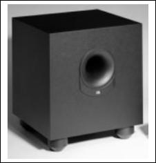
SUB135S Subwoofer
Configuration: |
Floor-firing, bass-reflex ported enclosure |
Woofer: |
8" cone |
Amplifier Power output: |
100W Continuous RMS power |
|
@ 0.8% THD, 20Hz to 100Hz |
LFE Input Voltage/Impedance: |
2V p-p/47k ohms |
Dimensions: |
Width: 13 inches (330mm) |
|
Height: 15 inches (381mm) |
|
Depth: 14 inches (356mm) |
Weight: |
30 lb/13.6kg |
Occasional refinements may be made to existing products without notice but will always meet or exceed original specifications unless otherwise stated
1
SUB135S |
100W Powered Amplifier |
|
|
||
|
|
|
|
|
|
LINE VOLTAGE |
Yes/No |
Hi/Lo Line |
Unit |
Notes |
|
EU 230vac/50Hz |
Yes |
108-132 |
Vrms |
Normal Operation |
|
Asia 100vac/50Hz |
Yes |
90-110 |
Vrms |
Normal Operation |
|
|
|
|
|
|
|
Parameter |
Specification |
Unit |
QA Test Limits |
Conditions |
Notes |
Amp Section |
|
|
|
|
|
Type (Class AB, D, other) |
AB |
AB |
n/a |
|
External Sink required for Class AB |
Load Impedance (speaker) |
4 |
Ohms |
n/a |
Nominal |
Z-curve required |
Rated Output Power |
100 |
Watts |
90 |
1 input driven |
|
THD@ Rated Power |
0.08 |
% |
0.3 |
22k filter |
|
THD @ 1 Watt |
0.1 |
% |
0.5 |
22k filter |
|
DC Offset |
10 |
mV-DC |
20 |
@ Speaker Outputs |
|
|
|
|
|
|
Measured at speaker terminals, Output power |
Damping factor |
>75 |
DF |
50 |
|
90 Watts THD 0.1 % |
|
|
|
|
|
|
Input Sensitivity |
|
|
|
|
|
Input Frequency |
50 |
Hz |
50 |
Nominal Freq. |
1 input driven |
LFE Input |
550 |
mVrms |
±2dB |
To Rated Power |
LFE input |
|
|
|
|
|
|
Signal to Noise |
|
|
|
|
|
SNR-A-Weighted |
100 |
dBA |
85 |
rel. to rated powe |
A-Weighting filter |
SNR-unweighted |
85 |
dBr |
85 |
rel. to rated powe |
22k filter |
SNR @ 1W-unweighted |
65 |
dBr |
60 |
rel. to 1W Output |
22k filter |
Residual Noise Floor |
1 |
mVrms |
1.5 |
Using RMS reading DMM/VOM (or A/P) |
LFE Input termintated with 600 Ohms |
|
|
|
|
UsingA/P Swept Bandpass Measurement |
|
Residual Noise Floor |
1 |
mVrms(max) |
1.5 |
(Line freq.+ harmonics) |
|
|
|
|
|
|
|
Input Impedance |
|
|
|
|
|
Line input L&R , LFE |
>15 |
K ohms |
n/a |
Nominal |
|
|
|
|
|
|
|
Filters |
|
|
|
|
|
Low Pass (fixed or variable) |
fixed |
-- |
±2dB |
|
|
Slope & Q |
|
dB/Octave |
n/a |
|
|
Subsonic filter (HPF) |
|
Hz |
±2dB |
|
|
Slope & Q |
|
dB/Octave |
n/a |
|
|
|
|
|
|
|
|
|
|
|
|
|
Limiter dirotrytion should not exceed 5% |
|
|
|
|
|
when input is overloaded by 3 times its input |
Limiter (yes/no) |
YES |
-- |
n/a |
|
sensistivity |
|
|
|
|
|
|
Features |
|
|
|
|
|
LFE Input |
YES |
|
functional |
|
BW Limited to 500 Hz |
ATO |
YES |
|
functional |
|
|
|
|
|
|
|
|
Signal Sensing (ATO) |
|
|
|
|
|
Auto-Turn-On (yes/no) |
YES |
-- |
functional |
|
|
ATO Input Frequency |
50 |
Hz |
functional |
|
|
ATO Level |
2 |
mV |
functional |
2mV@50Hz into Line Input w/ 1 ch. driven |
|
|
|
|
|
Amp connected and AC on, then input |
|
ATO Turn-on time |
5 |
ms |
functional |
signal applied |
|
Auto Mute/ Turn-OFF Time |
15 |
minutes |
functional |
T before muting, after signal is removed |
Auto turn of time (T) must be 10 > T <15 |
|
|
|
|
|
|
Power on Delay time |
3 |
sec. |
functional |
AC Power Applied |
|
|
|
|
|
|
|
Transients/Pops |
|
|
|
|
|
ATO Transient |
5 |
mV-peak |
10 |
@ Speaker Outputs |
|
Turn-on Transient |
50 |
mV-peak |
100 |
@ Speaker Outputs |
AC Line cycled from OFF to ON |
Turn-off Transient |
50 |
mV-peak |
100 |
@ Speaker Outputs |
AC Line cycled from ON to OFF |
|
|
|
|
|
|
Efficiency |
|
|
|
|
|
|
|
|
|
|
Maximum allowable input power under |
|
|
|
|
|
nominal Input voltage and frequency, HOT or |
Stand-by Input Power |
13 |
Watts |
15 |
@ nom. line voltage |
COLD operation. |
Power Cons.@rated power |
185 |
Watts |
195 |
@ nom. line voltage |
100 Watts @ 4 Ohms nominal line voltage |
|
|
|
|
|
|
Protection |
|
|
|
|
|
Short Circuit Protection |
YES |
-- |
functional |
Direct short at output |
|
Thermal Protection |
65 deg. C |
-- |
functional |
@1/8 max unclipped Power |
Temperature rise should not exceed 35K rise |
DC Offset Protection |
YES |
-- |
functional |
DC present at Speaker Out leads |
Relay or crowbar (for driver/fire protection |
Line Fuse Rating |
2.5 |
Amps |
2.5 |
Type-T or Slo Blo |
External fuse with UL/SEMKO rated holde |
2

Operating the SUB135S Subwoofer
1 2
LFE 
GREEN: ON
RED: STAND-BY
SUB135S |
|
POWER |
JBL, Incorporated |
|
3 |
This area is designed to become quite warm |
NRTL/C |
|
CSA 22-2 No.1 |
|
|
during normal operation |
UL 1492 |
|
CAUTION |
4 |
|
OF ELECTRIC SHOCK |
||
RISK DO NOT OPEN |
||
AVIS: RISQUE DE CHOC ELECTRIQUE-NE PAS OUVRIR |
FUSE |
|
T1.25A/250V |
||
|
||
|
TYPE T |
|
"WARNING: FOR CONTINUED |
AC 230V~50Hz |
|
|
PROTECTION AGAINST RISK |
||
"WARNING: TO REDUCE THE RISK OF FIRE OR ELECTRIC SHOCK, |
OR FIRE, REPLACE ONLY WITH |
||
200 Watts |
|||
DO NOT EXPOSE THIS APPLIANCE TO RAIN OR MOISTURE." |
SAME TYPE 2.5A, 250 VOLT |
||
"AVERTISSEMENT: POUR PR VENIR LES RISQUES D’INCENDIE OU |
"AVERTISSEMENT: UTILISEZ UN |
|
|
DE CHOC LECTRIQUE, VITER D’EXPOSER CET APPAREIL A LA |
FUSIBLE DE RECHANGE DE MEME |
|
|
PLUIE OU A L’HUMIDIT . " |
TYPE 2.5A, 250V" |
|
1 LFE Input: Connect to LFE/Subwoofer |
3 Power Switch: Turn the power switch to |
|
the subwoofer will not be used, turn this switch |
|||||
|
off to conserve electricity and for safety. |
|||||||
Output on rear panel of DCR600 receiver |
the “•” (dot) position to power the unit on. The |
|
||||||
|
|
|
|
|
|
|
||
using the single-lead RCA cable with brown |
SUB135S subwoofer will automatically turn |
|
4 |
AC Power Cord: Plug the power cord into |
||||
connectors. |
itself on and go into Standby (Sleep) mode |
|
||||||
|
an unswitched |
outlet. |
||||||
|
when left in the On position. When your |
|||||||
2 LED: Lights green when a low-frequency |
|
|
|
|
|
|
||
DCR600 is off, or is not sending program materi- |
|
|
|
|
|
|
||
signal is present and the subwoofer is playing. |
al to the subwoofer, the subwoofer will be in |
|
|
|
|
|
|
|
Lights red when no low-frequency audio signal |
Standby mode. When the subwoofer senses an |
|
|
|
|
|
|
|
is present to indicate that the subwoofer is |
audio signal, it will automatically turn itself on. |
|
|
|
|
|
|
|
plugged in, powered on and in the Standby |
If the subwoofer does not sense a signal after |
|
|
|
|
|
|
|
mode. |
approximately twenty minutes, it will automati- |
|
|
|
|
|
|
|
|
|
|
|
|
|
|||
|
cally go into Standby mode. If you will be away |
|
|
|
3 |
|
|
|
|
from home for an extended period of time, or if |
|
|
|
|
|
||
|
|
|
|
|
|
|
||
|
|
|
|
|
|
|
|
|
|
|
|
|
|
|
|
|
|
|
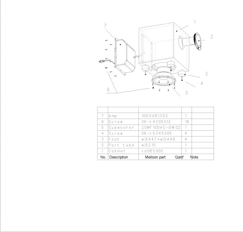
Num |
Description |
Part # |
Quantity |
|
|
|
|
|
|
|
|
1 |
Cabinet |
Not for Sale |
1 |
|
|
2 |
Port Tube |
Not for Sale |
1 |
|
|
3 |
Main Foot |
WI5447 |
4 |
|
|
|
Rubber pad for Foot |
WI5448 |
|
|
|
4 |
Screw |
|
4 |
|
|
5 |
8” Woofer |
20MF10DAG-DW02-01 |
1 |
|
|
6 |
Screw |
|
18 |
|
|
7 |
Amplifier Assembly |
Not for Sale |
1 |
|
|
|
|
|
|
|
|
|
|
|
|
|
SUB135S Test Set Up and Procedure
SYSTEM AURAL SWEEP TEST
Equipment needed:
•Function/signal generator/sweep generator
•Integrated Amplifier
•Multimeter
General Unit Function (UUT = Unit Under Test)
1.From the signal generator (set initially at 0 volts), connect one line level (RCA) cable to the SUB135S LFE jack on the UUT.
2.Plug in the power cord; turn the power switch ON. LED should be Red.
3.Turn up the generator and adjust to 300mV, 40 Hz. LED should now be Green.
4.Immediate bass response should be heard and felt from port tube opening.
Sweep Function
1.Follow steps 1-4 above, using a sweep generator as a signal source.
2.Sweep generator from 20Hz to 1kHz. Listen to the cabinet and drivers for any rattles, clicks, buzzes or any other noises. If any unusual noises are heard, remove woofer and test.
Driver Function (Woofer)
1.Remove woofer from cabinet; detach the + and - wire clips.
2.Check DC resistance of woofer; it should be 3.4 ohms ±10%.
3.Connect a pair of speaker cables to driver terminals. Cables should be connected to an integrated amplifier fed by a signal generator. Turn on generator and adjust so that speaker level output is 5.0V.
5.Sweep generator from 20Hz to 1kHz. Listen to driver for any rubbing, buzzing, or other unusual noises.
Caution: take care to replace the + and - wire clips on the correct terminals, as they are the same size. Red wire should connect to the red dot on the terminal.
5
 Loading...