


SUB200
Surround Cinema
SUB200
Amplifier/Subwoofer
SERVICE MANUAL
JBL Consumer Products
250 Crossways Park Dr.
Woodbury, New York 11797 Rev1 3/2005

SUB200 (SCS200.7 sys)
1
Note: The SUB200 is part of the SCS200.7 system
Satellite loudspeakers SCS200SAT order JBL part# SCS200SAT-1
Center channel SCS200CEN order JBL part# SCS200/300 CEN-1
- CONTENTS -
BASIC SPECIFICATIONS……………….….….….….…………….1
DETAILED SPECIFICATIONS ……..…………….……………..2
OPERATION ………….……………………………..…………….4
CONNECTIONS..………………………..………….…….………...5
BASIC TROUBLESHOOTING…..…………….….….…….……...7
TEST SET-UP AND PROCEDURE……..……….…….………….8
EXPLODED VIEW/PARTS LIST…………………………………..9
120V BLOCK DIAGRAM..……………………….…………….....10
230V BLOCK DIAGRAM..………………………….………….....11
PCB DRAWINGS………………..………………………………...12
120V ELECTRICAL PARTS LIST …………….…….…………..18
230V ELECTRICAL PARTS LIST …………….….……………..22
INTEGRATED CIRCUIT/TRANSISTOR PINOUTS…………..26
120V SCHEMATICS.……….………………………..…. ………27
230V SCHEMATICS.………..……………………….…. ………29
PACKAGING…………………………….………………………...31
BASIC SPECIFICATIONS
SUB200 Subwoofer
Configuration: Floor-firing, bass-reflex ported enclosure
Woofer: 8" (203mm) cone
Amplifier Power output: 100W Continuous RMS power
Frequency response: 35Hz – 160Hz (-6dB)
Dimensions (including feet): 16 ¼ x 11 x 13 ¾” (413 x 279 x 349mm)
Weight: 28 lb/12.7kg
Occasional refinements may be made to existing products without notice but will always meet or exceed original
specifications unless otherwise stated
P
A
SUB200 (SCS200.7sys)
2
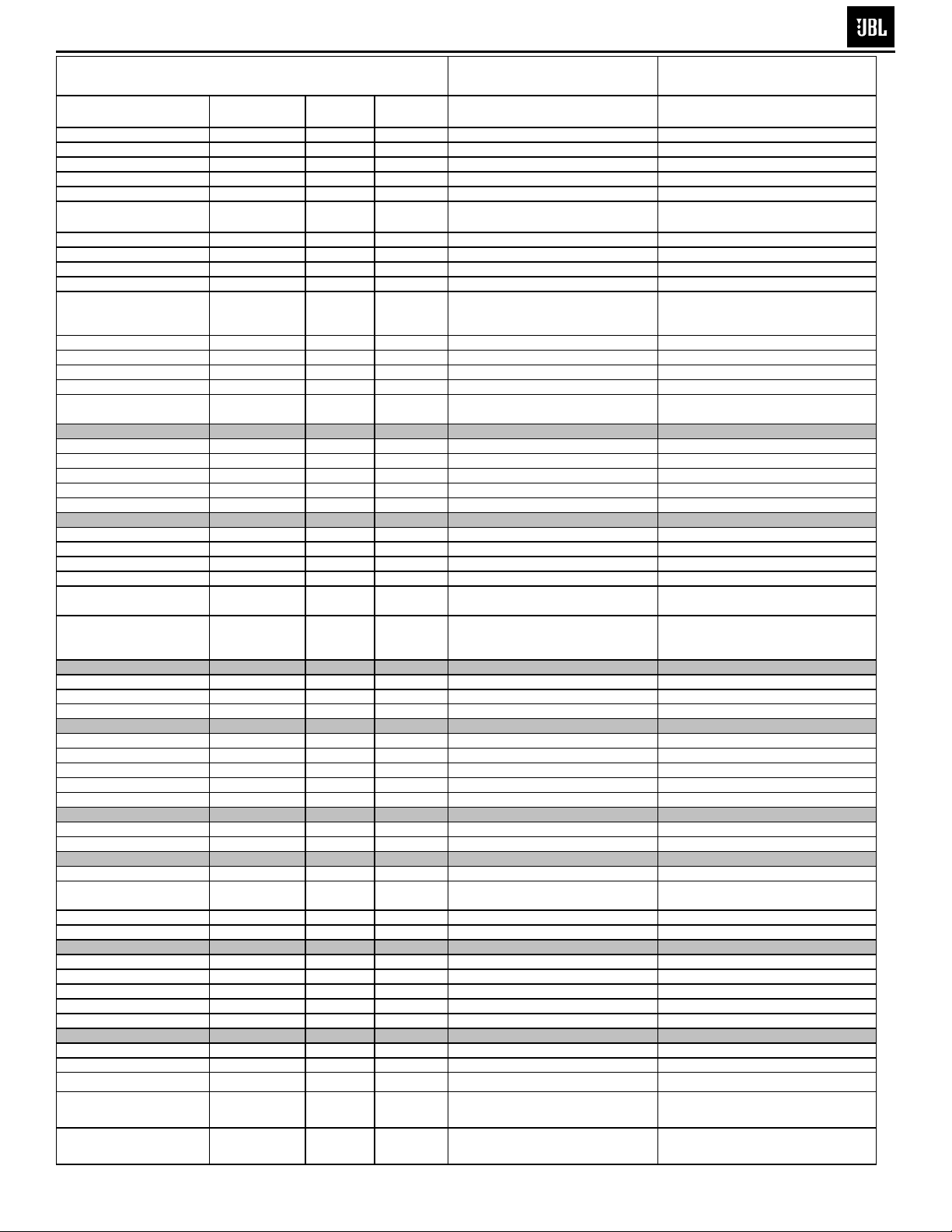
JBL SUB200 100W Powered Sub/ Plate Amp
LINE VOLTAGE Yes/No Hi/Lo Line Unit Notes
Parameter Specification Unit
Amp Section
Type (Class AB, D, other) AB AB
Type (Class AB, D, other) H H
Load Impedance (speaker) 4 Ohms
Rated Output Power 120V 100 Watts
Rated Output Power 230V 105 Watts
THD@ Rated Power 0.5 %
THD @ 1 Watt 0.1 %
DC Offset 10 mV-DC
Damping factor >100 DF
Input Sensitivity
Signal to Noise
SNR-A-Weighted 90 dBA
SNR-unweighted 80 dBr
SNR @ 1W-unweighted 65 dBr
Residual Noise Floor 1.5 mVrms
Residual Noise Floor 1
US 120VAC/60Hz Yes 108-132 Vrms
Asia 100VAC/50Hz Yes 90-110 Vrms
EU 230VAC/50-60Hz Yes 207-264 Vrms Normal Operation Normal operation, MOMS required
QA Test
Limits Conditions Notes
N/A 120V System is Class AB
N/A 230V System is Class H
N/A Nominal
100 @ Nominal input voltage
0.3 22K filter
Input Frequency 50 Hz
Line Input (L&R) 15 mVrms
LFE Input 9.5 mVrms
Speaker/Hi Level Input 245 mVrms
mVrms(max)
±2dB To 1 Watt 1 input driven
±2dB To 1 Watt LFE input driven only
±2dB To 1 Watt (-20 dB below Line In)...1 input driven
2.5
Normal Operation
Normal Operation
Different output power due to differences
85 @ Nominal input voltage
1 22K filter
50 @ Speaker Output
50
50 Nominal Freq.
85 To Rated power A-Weighting filter
80 To Rated power 22KHz filter
60 To 1 Watt 22KHz filter
Volume @max, using RMS reading
DMM/VOM (or A/P)
Volume @max, w/ A/P Swept
Bandpass Measurement (Line freq.+
2
harmonics)
in amp configuration between 120V and
230V
Measured at speaker terminals, Output
power 90 Watts THD 0.1 %
Input Impedance
Line input L&R , LFE >10 K ohms
Speaker/Hi Level Input 4.7 K ohms
Filters
Low Pass (fixed or variable) fixed --
Subsonic filter (HPF) Hz
Limiter (yes/no) YES -THD at Max. Output Power N/A --
Features
LFE Input YES
Volume pot Taper (lin/log) LOG -ATO YES
Input Configuration
Line In (L,R) L ,R -Line level in LFE LFE
Spkr/Hi Level In
Spkr Out: Level out (L,R)Hi
Signal Sensing (ATO)
Auto-Turn-On (yes/no) YES -ATO Input Frequency 50 Hz
TO Level Line Level in (L,R 2 mV
Slope & Q dB/Octave
Slope & Q dB/Octave
(L,R)
L,R -L,R
N/A Nominal over the audio BW Reference only
N/A Nominal over the audio BW Reference only
±2dB
N/A
±2dB
N/A
N/A
N/A
Functional
Functional
Functional
Functional RCA inputs: L , R Summed to Mono
Functional
Functional L R Summed to Mono
Functional Direct by pass from Speaker in
Functional
Functional
Functional
2mV@50Hz into Line Input w/ 1 ch.
driven
BW Limited to 500 Hz, refer to
ECR00031 & AP Curves
ATO Level Speaker in 40 mV
Functional
SUB200 (SCS200.7sys)
3
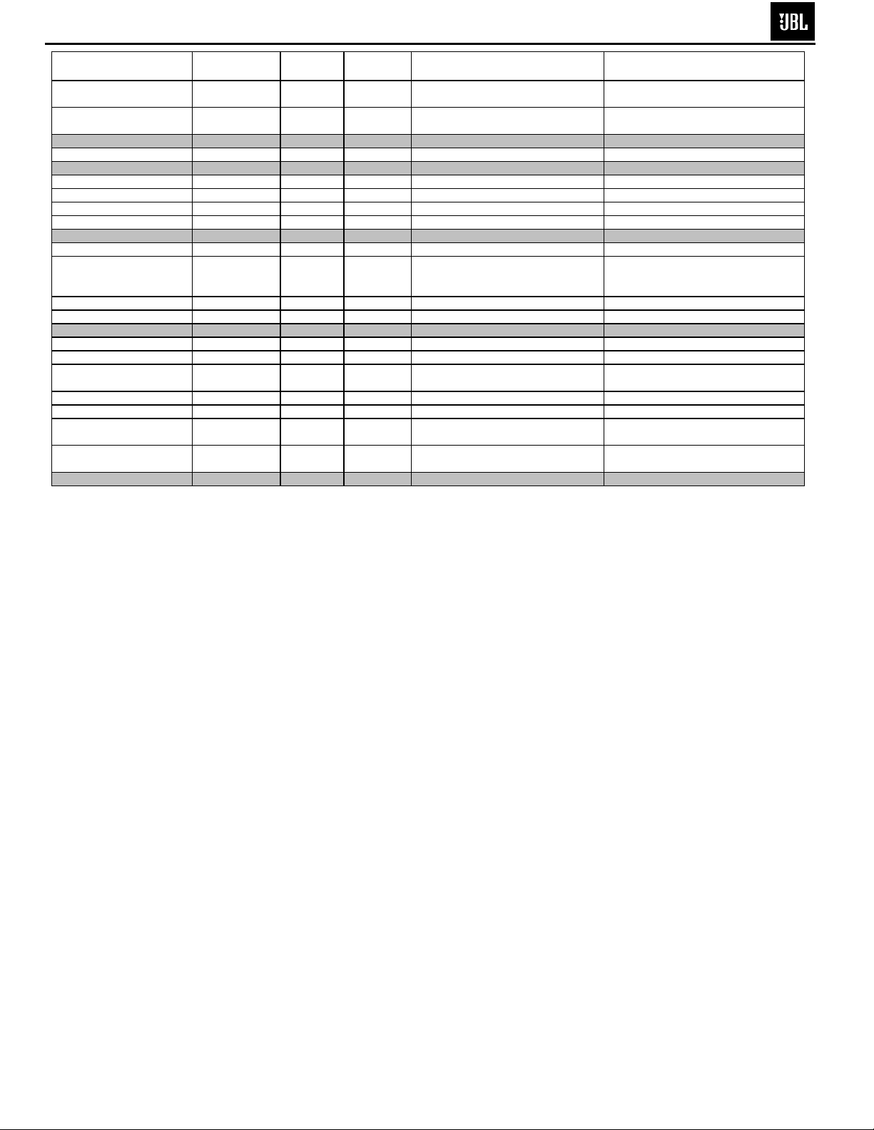
Parameter Specification Unit
ATO Turn-on time 5 ms
Auto Mute/ Turn-OFF Time 15 minutes
QA Test
Limits Conditions Notes
Functional
Functional
Amp connected and AC on, then input
signal applied
T before muting, after signal is
removed Auto turn of time (T) must be 10 > T <15
Power on Delay time 3 sec.
Transients/Pops
ATO Transient 5 mV-peak
Turn-on Transient 50 mV-peak
Turn-off Transient 50 mV-peak
Efficiency
Stand-by Input Power 12 Watts
Power Cons.@rated power 180 Watts
Power Cons.@rated power 195 Watts
Protection
Short Circuit Protection YES --
Thermal Protection 65 deg. C -DC Offset Protection YES -Line Fuse Rating
120VAC 2.5 Amps
230VAC 1.25 Amps
Functional AC Power Applied
10 @ Speaker Outputs
100 @ Speaker Outputs AC Line cycled from OFF to ON
100 @ Speaker Outputs AC Line cycled from ON to OFF
Maximum allowable input power under
13 @ nom. line voltage
187 @ 120V-60 Hz (Nom.line voltage)
200 @ 230V-50 Hz (Nom.line voltage)
Functional Direct short at output
Functional @1/8 max unclipped Power
Functional DC present at Speaker Out leads Relay or crowbar (for driver/fire
Type-T or Slo Blo
Type-T or Slo Blo
nominal Input voltage and frequency,
HOT or COLD operation.
90 Watts @ 4 Ohms nominal line voltage
90 Watts @ 4 Ohms nominal line voltage
Temperature rise should not exceed 35K
rise
External fuse with UL/SEMKO rated
holder
External fuse with UL/SEMKO rated
holder
10
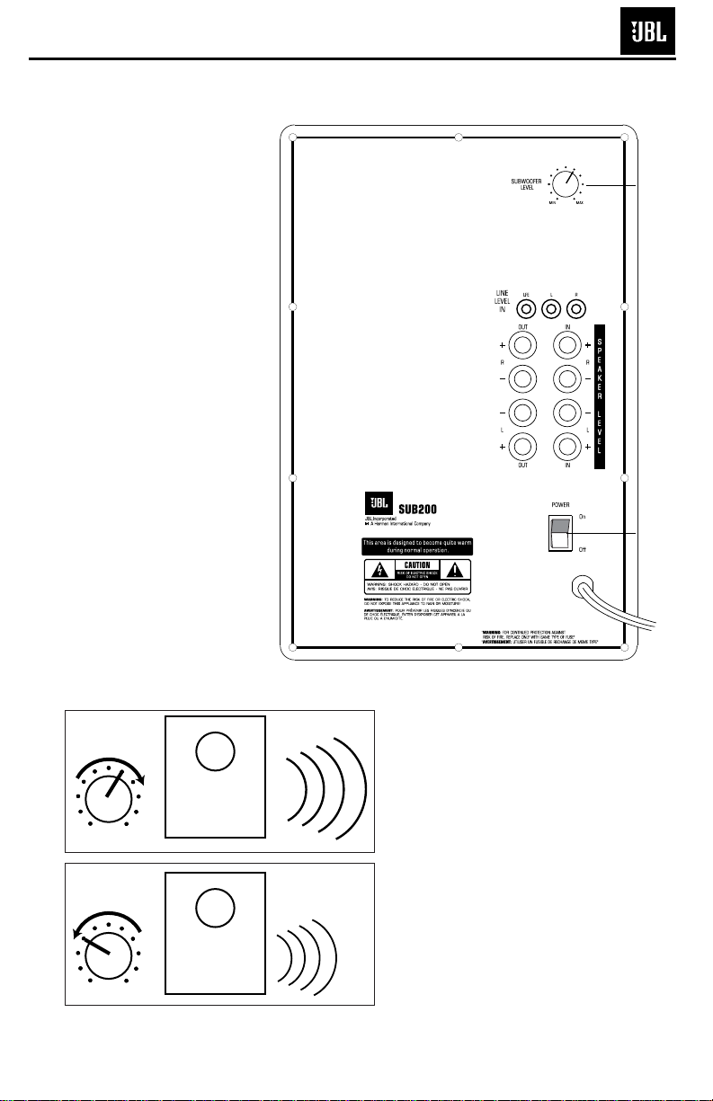
OPERATION
MIN MAX
Subwoofer
Level
MIN MAX
Subwoofer
Level
Move the Master Power
switch (marked “Power”
å)
to the “•” (On) position to
use the SUB200 subwoofer.
If you will be away from
home for an extended period
of time, or if the subwoofer
will not be used, switch the
Master Power switch
å to
the Off position.
VOLUME
Volume may be adjusted
using the Subwoofer Level
control
∫ as shown.
SUB200 (SCS200.7sys)
4
∫
å
8
DOLBY PRO LOGIC* (NON-DIGITAL)
–
LINE LEVEL
Use this installation method
for Dolby Pro Logic applications (not Dolby Digital, DTS
or other digital processing),
where the receiver/processor is equipped with a subwoofer output, or a volumecontrolled preamp (line-)
level output:
Use RCA-type interconnects
to connect the line-level
subwoofer outputs on your
receiver or amplifier to the
line-level inputs on the subwoofer. IMPORTANT: Do not
use the LFE input on the subwoofer with Dolby Pro Logic
processors.
NOTE: If your receiver or
amplifier only has one subwoofer output jack, then you
will need to use a Y-connector (not included). Plug the
male end of the Y-connector
into your receiver or amplifier’s subwoofer output jack,
and connect each of the two
female ends to separate
RCA-type interconnects.
Finally, plug the RCA-type
interconnects into the linelevel inputs on the subwoofer.
Connect each speaker to
the corresponding speaker
terminals on your receiver
or amplifier.
Make sure your receiver or
processor is correctly configured to indicate that the
subwoofer is “On.”
Note for advanced users: If
your receiver/processor has
a built-in low-pass crossover
filter for the subwoofer output, you may use the LFE
input to bypass the subwoofer’s internal crossover.
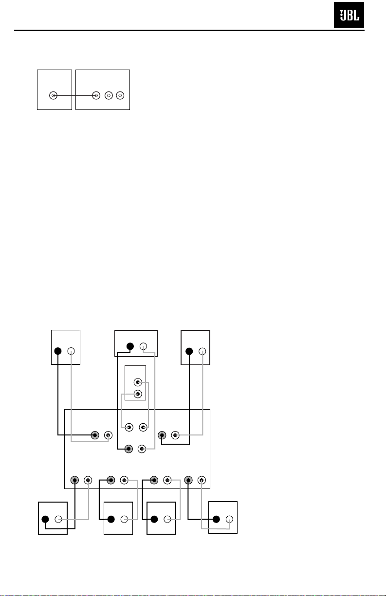
Use this installation method
for Dolby Digital, DTS or
other digital surround
processors:
Use the line-level input jack
marked “LFE” for the LowFrequency Effects channel.
Connect this jack to the LFE
output or subwoofer output
on your receiver or amplifier.
Connect each speaker to the
corresponding speaker
terminals on your receiver
or amplifier.
Make sure that you have
configured your surround
sound processor for “Subwoofer On.” Also configure
your receiver for 5.1-, 6.1- or
7.1-channel operation as
appropriate. The front left,
front right, center and rear
speakers should all be set to
“Small.” If your receiver
allows you to set the crossover frequency between the
subwoofer and the main
speakers, select
120Hz or the
setting that is the closest frequency below it.
DOLBY* DIGITAL OR DTS
®
(OR OTHER DIGITAL SURROUND MODE) CONNECTION
LINE
LEVEL
IN
LFE L R
LFE OUT
SUBWOOFER
RECEIVER
– +
– +
– +
– +
– +
– +
– +
– +– +
Receiver
Subwoofer
Out
Left
Front
Left
Surround
– +
Right
Front
Right
Surround
Subwoofer
R L
Center
Surround Back
Left
Line-
Level In
Right Surround
Right Front
Left Surround
Left Front
Center
R
L
– +
Surround Back
Left
– +
– +
Surround Back
Right
– +
Surround Back
Right
SUB200 (SCS200.7sys)
5
9
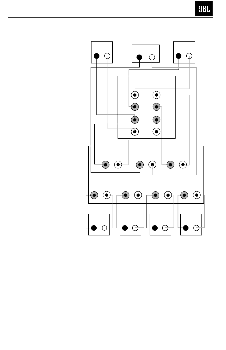
DOLBY PRO LOGIC (NON-DIGITAL) –SPEAKER LEVEL
Use this installation method
for Dolby Pro Logic applications (not Dolby Digital, DTS
or other digital processing),
where the receiver/processor
does not have a subwoofer
output, or a volume-controlled
preamp (line-) level output:
Connect your receiver or
amplifier’s front left and right
speaker terminals to the left
and right terminals on the
subwoofer that are marked
“Speaker Level In.” Connect
the left and right terminals
on the subwoofer that are
marked “Speaker Level Out”
to the corresponding terminals on the back of your front
left and right speakers.
Connect your receiver or
amplifier’s center, surround
and surround back speaker
terminals to the corresponding terminals on the back of
your center and surround
speakers.
Right Front
Right Surround
Left Front
Left Surround
Center
– + – +
– +
– + – +
– +
– +
– + – +
– +
Left Front Center
Left Surround
Right Front
Right Surround
Surround Back
Left
Surround Back
Left
Subwoofer
Receiver
SPEAKER LEVEL
OUT IN
+
R
–
+
R
–
–
L
+
–
L
+
– +
– +
Surround Back
Right
Surround Back
Right
– + – +
SUB200 (SCS200.7sys)
6

If there is no sound from any
of the speakers:
• Check that receiver/amplifier is on and a source is
playing.
• Check that the powered
subwoofer is plugged in,
and its
Power switch å is
switched on (“•” position).
• Check all wires and connections between receiver/
amplifier and speakers.
Make sure all wires are connected. Make sure none of
the speaker wires are
frayed, cut or punctured, or
touching each other.
• Review proper operation of
your receiver/amplifier.
If there is no sound coming
from one speaker:
• Check the “Balance” control
on your receiver/amplifier.
• Check all wires and connections between receiver/
amplifier and speakers.
Make sure all wires are connected. Make sure none of
the speaker wires are
frayed, cut or punctured, or
touching each other.
• In Dolby Digital or DTS
modes, make sure that the
receiver/processor is configured so that the speaker in
question is enabled.
• Turn off all electronics
and switch the speaker in
question with one of the
other speakers that is working correctly. Turn everything back on, and determine whether the problem
has followed the speaker, or
has remained in the same
channel. If the problem is
in the same channel, the
source of the problem
is most likely with your
receiver or amplifier, and
you should consult the
owner’s manual for that
product for further information. If the problem has followed the speaker, consult
your dealer for further assistance or, if that is not possible, visit www.jbl.com.
If there is no sound from the
center speaker:
• Check all wires and connections between receiver/
amplifier and speaker. Make
sure all wires are connected.
Make sure none of the
speaker wires are frayed,
cut or punctured, or touching each other.
• If your receiver/processor
is set in Dolby Pro Logic mode,
make sure the center speaker
is not in phantom mode.
• If your receiver/processor
is set in one of the Dolby
Digital or DTS
modes, make
sure the receiver/
processor
is configured so that the
center speaker is enabled.
If the system plays at low
volumes but shuts off as
volume is increased:
• Check all wires and connections between receiver/
amplifier and speakers.
Make sure all wires are connected. Make sure none of
the speaker wires are
frayed, cut or punctured, or
touching each other.
• If more than one pair of
main speakers is being used,
check the minimum impedance requirements of your
receiver/amplifier.
If there is low (or no) bass
output:
• Make sure the connections
to the left and right “Speaker
Inputs” have the correct
polarity (+ and –).
• Make sure the subwoofer
is plugged into an active
electrical outlet
, and is
turned on (Power switch å
in the “•” position).
• In Dolby Digital or DTS
modes, make sure your
receiver/processor is configured so that the subwoofer
and LFE output are enabled.
If there is no sound from
the surround speakers:
• Check all wires and connections between receiver/
amplifier and speakers.
Make sure all wires are connected. Make sure none of
the speaker wires are
frayed, cut or punctured, or
touching each other.
• Review proper operation of
your receiver/amplifier and
its surround sound features.
• Make sure the movie or
TV show you are watching
is recorded in a surround
sound mode. If it is not,
check to see whether your
receiver/amplifier has other
surround modes you may use.
•
In Dolby Digital or DTS
modes, make sure your
receiver/processor is configured so that the surround
speakers are enabled. When
five satellites are in use,
remember to configure your
receiver or processor for
6.1-channel operation, and
when all six satellites are in
use, configure your receiver
or processor for 7.1 channels.
• Review the operation of
your DVD player and the
jacket of your DVD to make
sure that the DVD features
the desired Dolby Digital or
DTS mode, and that you
have properly selected that
mode using both the DVD
player’s menu and the DVD
disc’s menu.
TROUBLESHOOTING
11
SUB200 (SCS200.7sys)
7

SUB200 (SCS200.7sys)
8
SUB200 Test Set Up and Procedure
Equipment needed:
• Function/signal generator/sweep generator
• Integrated Amplifier
• Multimeter
• Speaker cables
General Unit Function (UUT = Unit Under Test)
1) From the signal generator, connect one line level (RCA) cable to the Subwoofer Line Level Input jacks L/R
on the UUT. Use a Y-cable from a mono source if necessary to connect to both inputs. Do not connect to
the single LFE input.
2) Turn the LEVEL control on the UUT to completely counterclockwise (MIN).
3) Turn on generator; adjust to 100mV, 50 Hz.
4) Plug in UUT; turn the power switch ON. LED should switch from Red to Green. Turn LEVEL control full
clockwise (MAX)
5) LED should Green; immediate and vigorous bass response should be heard and felt from port tube
opening.
6) Turn off generator, turn LEVEL control full counterclockwise (MIN), and disconnect RCA cable.
7) Connect one pair
of speaker cables to Speaker Level input terminal (IN) on UUT. Cables should be
connected to an integrated amplifier fed by the signal generator.
8) Turn on generator and adjust so that speaker level input at the amplifier is 2.0V, 50 Hz. Turn LEVEL control
full clockwise (MAX).
9) Green LED should light; immediate and vigorous bass response should be heard and felt from the port
tube opening.
Sweep Function
1) Follow steps 6-8 above, using a sweep generator as a signal source.
2) Sweep generator from 20Hz to 300Hz. Listen to the cabinet and drivers for any rattles, clicks, buzzes or
any other noises. If any unusual noises are heard, remove woofers and test.
Driver Function
1) Remove woofer from cabinet (instructions on exploded view drawing); detach + and - wire clips.
2) Check DC resistance of woofer; it should be 3.4 ohms ±10%
3) Connect a pair of speaker cables to driver terminals. Cables should be connected to an integrated amplifier
fed by a signal generator. Turn on generator and adjust so that speaker level output is 5.0V.
4) Sweep generator from 20Hz to 1kHz. Listen to driver for any rubbing, buzzing, or other unusual noises.
SUB200 (SCS200.7sys)
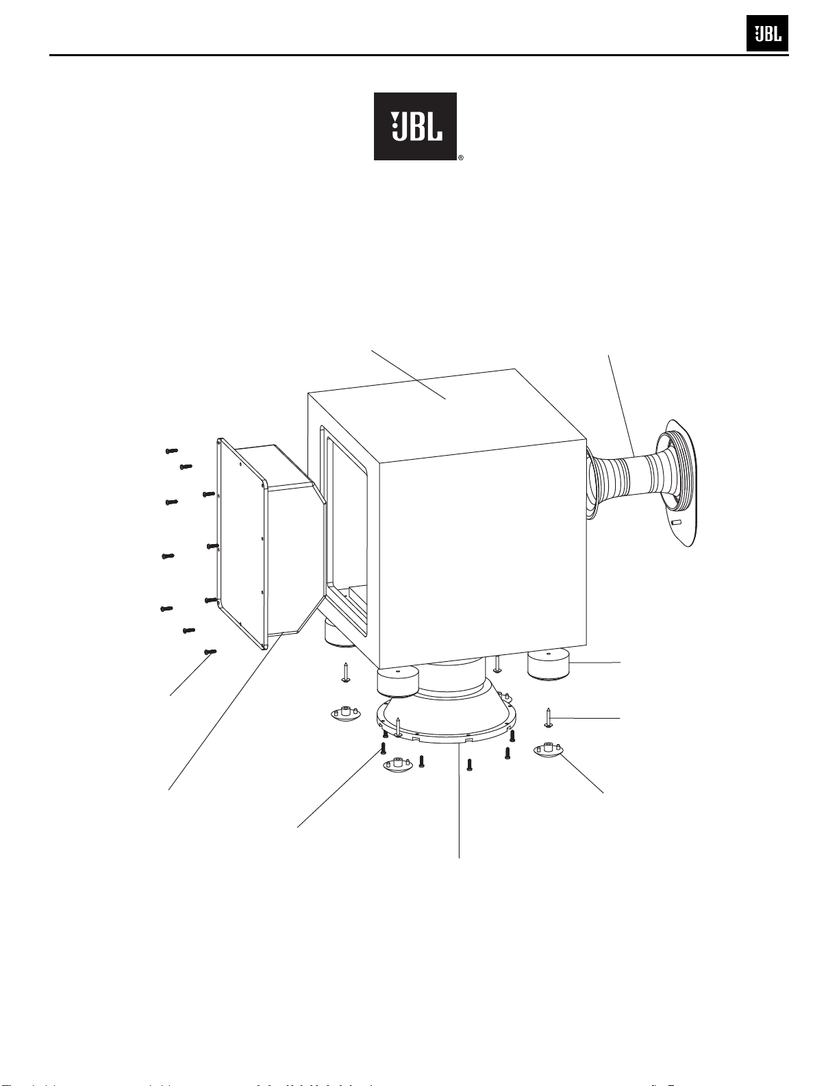
9
SUB200
Exploded View
Amplifier Screw (10)
352-AM04020D210
SUB200 Cabinet
Not For Sale
Port Tube
249-ABS-00174
Main Body Plastic Foot (4)
321-ABS-00008
Foot Screw (4)
352-HM04030D500
SUB200 Amplifier
Not For Sale
Woofer Screw (8)
352-FM04020D605
8" Woofer DCR=3.4Ω
20MF10DAG-DW04
Rubber Foot Base (4)
321-ABS-00009
 Loading...