


User’s Guide
SRX812P SRX815P SRX835P SRX818SP SRX828SP

2

|
CONTENTS |
|
|
Safety Instructions..................................................................................................................................... |
4 |
Declaration Of Conformity.......................................................................................................................... |
5 |
Quick Setup Guide...................................................................................................................................... |
6 |
SRX812P, SRX815P, SRX835P Back Panel.................................................................................................. |
8 |
SRX828SP, SRX818SP Back Panel........................................................................................................... |
10 |
Overview - SRX800 Family....................................................................................................................... |
12 |
SRX812P, SRX815P - Block Diagram....................................................................................................... |
13 |
SRX835P - Block Diagram....................................................................................................................... |
14 |
SRX818SP - Block Diagram..................................................................................................................... |
15 |
SRX828SP - Block Diagram..................................................................................................................... |
16 |
SRX812P Specifications .......................................................................................................................... |
17 |
SRX815P Specifications .......................................................................................................................... |
18 |
SRX835P Specifications .......................................................................................................................... |
19 |
SRX818SP Specifications ........................................................................................................................ |
20 |
SRX828SP Specifications ........................................................................................................................ |
21 |
Purposeful Product Design...................................................................................................................... |
22 |
Component Elements............................................................................................................................... |
23 |
Back Panel LCD........................................................................................................................................ |
25 |
SRX Presets.............................................................................................................................................. |
27 |
Premium DSP Technology........................................................................................................................ |
29 |
Networking............................................................................................................................................... |
30 |
Smart Device App..................................................................................................................................... |
32 |
Loudspeaker Placement and Suspension............................................................................................... |
33 |
TroubleShooting....................................................................................................................................... |
34 |
Warranty Information............................................................................................................................... |
35 |
Contact Information................................................................................................................................. |
36 |
3

Safety Instructions
Before You Begin - Important Safety Information
Before using your SRX800® speaker system please review the following for important information on safety and protection of your investment in quality loudspeakers.
1.Read these instructions.
2.Keep these instructions.
3.Follow all instructions.
4.Heed all warnings.
5.Do not use this apparatus near water.
6.Clean only with dry cloth.
7.Do not block any ventilation openings. Install in accordance with the manufacturer’s instructions.
8.Do not install near any heat sources such as radiators, heat registers, stoves, or other apparatus (including amplifiers) that produce heat.
9.Do not defeat the safety purpose of the polarized or grounding-type plug. A polarized plug has two blades with one wider than
the other. A grounding-type plug has two blades and a third grounding prong. The wide blade or the third prong is provided for your safety. If the provided plug does not fit into your outlet, consult an electrician for replacement of the obsolete outlet.
10.Protect the power cord from being walked on or pinched, particularly at plugs, convenience receptacles, and the point where they exit from the apparatus.
11.Only use attachments/accessories specified by the manufacturer.
12.Use only with the cart, stand, tripod, bracket, or table specified by the manufacturer, or sold with the
apparatus. When a cart is used, use caution when moving the cart/apparatus combination to avoid injury from tip-over.
13. Unplug this apparatus during lightning storms or when unused for long periods of time.
14.Refer all servicing to qualified service personnel. Servicing is required when the apparatus has been damaged in any way, such as power supply cord or plug is damaged, liquid has been spilled or objects
have fallen into the apparatus, the apparatus has been exposed to rain or moisture, does not operate normally, or has been dropped.
15.CAUTION - DO NOT PERFORM ANY SERVICING UNLESS YOU ARE QUALIFIED TO DO SO.
16.To completely disconnect this apparatus from the AC mains, disconnect the power supply cord plug from the AC receptacle.
17.WARNING – TO REDUCE THE RISK OF FIRE OR ELECTRIC – SHOCK, DO NOT EXPOSE THIS APPARATUS TO RAIN OR MOISTURE.
18.Do not expose this equipment to dripping or splashing and ensure that no objects filled with liquids, such as vases, are placed on the equipment.
19.THE MAINS PLUG OF THE POWER SUPPLY CORD SHALL REMAIN READILY OPERABLE.
4

|
Declaration Of Conformity |
|
|
Safety And EMC Compliance Specifications |
|
Report No. |
Description |
EN 55103-1:2009 +A1:2012 |
EMC Compatibility – Product Family Standard for Audio, Video, Audio-Visual and Entertainment Lighting Control |
|
Apparatus for Professional Use, Part 1: Emissions |
EN 55103-1:2009 +A1:2012 |
Magnetic Field Emissions – Annex A @ 10cm and 20cm |
EN 61000-3-2:2006 +A1:2008 +A2:2009 Limits for Harmonic Current Emissions (equipment input current less than or equal to 16A |
|
EN 61000-3-3:2013 |
Limitation of Voltage Fluctuations and Flicker in Low-Voltage Supply systems Rated Current less than |
|
or equal to 16A |
EN 55022:2010 |
Limits and Methods of Measurement of Radio Disturbance Characteristics of ITE: Radiated, Class B Limits; |
|
Conducted, Class A |
EN 55103-2:2009 |
EMC Compatibility – Product Family Standard for Audio, Video, Audio-Visual and Entertainment Lighting Control |
|
Apparatus for Professional Use, Part 2: Immunity |
EN 61000-4-2:2008 Ed 2.0 |
Electrostatic Discharge Immunity (Environment E2-Criteria B, 4k V Contact, 8k V Air Discharge) |
EN 61000-4-3:2010 Ed 3.2 |
Radiated, Radio-Frequency, EMC Immunity (Environment E2, Criteria A) |
EN 61000-4-4:2007 |
Electrical Fast Transient/Burst Immunity (Criteria B) |
EN 61000-4-5:2006 |
Surge Immunity (Criteria B) |
EN 61000-4-6:2006 |
Immunity to Conducted Disturbances Induced by Radio-Frequency Fields (Criteria A) |
EN 61000-4-11:2004 |
Voltage Dips, Short Interruptions and Voltage Variation |
Safety Standard: |
|
EN60065:2002 +A12:2011, |
Safety Requirements – Audio, Video, and Similar Electronic Apparatus |
IEC 60065:2001 Ed 7 |
|
+A1:2005 +A2:2010 |
|
CAN/CSA 60065-03 incl. A1 |
Safety Requirements – Audio, Video, and Similar Electronic Apparatus |
UL Std No. 60065-2007 |
Safety Requirements – Audio, Video, and Similar Electronic Apparatus |
UL Compliance Specifications
UL 60065 7th Ed. CAN/CSA 22.2 No.60065_2003
FCC Statement
1.This device complies with Part 15 of the FCC Rules. Operation is subject to the following two conditions:
(1)This device may not cause harmful interference.
(2)This device must accept any interference received, including interference that may cause undesired operation.
2.Changes or modifications not expressly approved by the party responsible for compliance could void the user’s authority to operate the equipment.
NOTE: This equipment has been tested and found to comply with the limits for a Class B digital device, pursuant to Part 15 of the FCC Rules. These limits are designed to provide reasonable protection against harmful interference in a residential installation.
This equipment generates uses and can radiate radio frequency energy and, if not installed and used in accordance with the instructions, may cause harmful interference to radio communications. However, there is no guarantee that interference will not occur in a particular installation. If this equipment does cause harmful interference to radio or television reception, which can be determined by turning the equipment off and on, the user is encouraged to try to correct the interference by one or more of the following measures:
•Reorient or relocate the receiving antenna.
•Increase the separation between the equipment and receiver.
•Connect the equipment into an outlet on a circuit different from that to which the receiver is connected.
•Consult the dealer or an experienced radio/TV technician for help.
FCC Radiation Exposure Statement
This equipment complies with FCC radiation exposure limits set forth for an uncontrolled environment. This equipment should be installed and operated with
minimum distance 20cm between the radiator & your body.
IC Warning
1.This device complies with Industry Canada licence-exempt RSS standard(s). Operation is subject to the following two conditions:
(1)this device may not cause interference, and
(2)this device must accept any interference, including interference that may cause undesired operation of the device.
2.Changes or modifications not expressly approved by the party responsible for compliance could void the user’s authority to operate
the equipment.
Le présent appareil est conforme aux CNR d’Industrie Canada applicables aux appareils radio exempts de licence. L’exploitation est autorisée aux deux conditions suivantes :
(1)l’appareil ne doit pas produire de brouillage, et
(2)l’utilisateur de l’appareil doit accepter tout brouillage radioélectrique subi, même si le brouillage est susceptible d’en compromettre le fonctionnement.”
5
Quick Setup Guide
Congratulations on your purchase of JBL Professional SRX800 Series loudspeakers! We know you are anxious to get up and running as fast as possible, which is why you are reading this section. The following will help you get set up as soon as possible.
Packaging Contents
Your SRX800 system should include the following: 1 x SRX800 speaker
1 x 10'(3m) IEC Power Cable
1 x Quick Start Guide
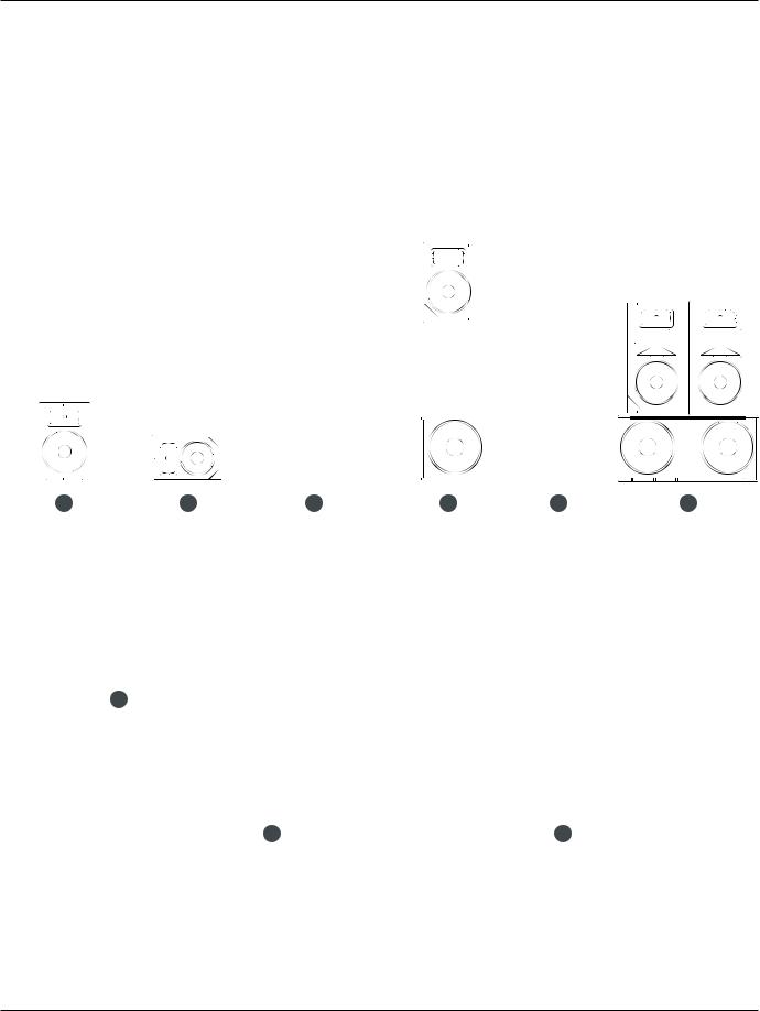
Configuration Options
1 |
2 |
3 |
4 |
5 |
6 |
--Standing (SRX812P, SRX815P, SRX835P)
--Monitor (SRX812P, SRX815P)
--Pole Mounted (SRX12P, SRX815P, SRX835P)
--Sub Mounted (SRX812P, SRX815P, SRX835P)
--Suspended (SRX812P, SRX815P, SRX835P)
--Stacked Subs (SRX818SP, SRX828SP)
--Cardiod Subs (SRX818SP, SRX828SP)
7
|
|
----Standing(SRX812P, SRX815P,, SRX835P), |
|
|
|
----Monitor(SRX812P, SRX815P), |
|
|
|
----PolePoleMounted(SRX12P, SRX815P,, SRX835P), |
|
|
|
----SubMounted(SRX812P, SRX815P,, SRX835P), |
|
|
|
----Suspended(SRX812P, SRX815P,, SRX835P), |
|
|
|
----Stacked8Subs(SRX818SP, SRX828SP), |
9 |
|
|
----CardiodSubs(SRX818SP, SRX828SP), |
|
1. |
Floor Standing |
6. |
Subs with 3-way splayed |
X815P,2P, SRX815P,--SRX835P)StandingSRX835P)(SRX812P, SRX815P, SRX835P) |
7. |
Stacked Subs |
|
2. |
Monitor |
||
815P), SRX815P)-- Monitor (SRX812P, SRX815P) |
|
|
|
RX12P,, SRX815P,--SRX815PoleSRX835P)Mounted, SRX835P)(SRX12P, SRX815P, SRX835P) |
8. |
Cardiod Subs |
|
3. |
Pole Mounted |
||
RX812P,SRX815P,--, SubRX815P,SRX835P)MountedSRX835P)(SRX812P, SRX815P, SRX835P) |
|
|
|
SRX815P,812P, SRX815P,-- SuspendedSRX835P)SRX835P)(SRX812P, SRX815P, SRX835P) |
9. |
Cardiod Subs Vertical |
|
4. |
Sub Mounted |
||
SP,X818SP,SRX828SP)-- StackedSRX828SP)Subs (SRX818SP, SRX828SP) |
|
|
|
SP,X818SP,SRX828SP)-- CardiodSRX828SP)Subs (SRX818SP, SRX828SP) |
|
|
|
5. |
Suspended |
|
|
|
|
-- Standing (SRX812P, SRX815P, SRX835P) |
|
6 |
|
-- Monitor (SRX812P, SRX815P) |
|
|
-- Pole Mounted (SRX12P, SRX815P, SRX835P) |
||
-- Sub Mounted (SRX812P, SRX815P, SRX835P)
-- Suspended (SRX812P, SRX815P, SRX835P)
-- Stacked Subs (SRX818SP, SRX828SP)

Quick Setup Guide
LCD Screen |
|
Power LED |
|
Power Button |
Master Encoder |
|
CH1 Direct Out
CH1 Input
CH1 Encoder 
CH2 Encoder 
|
MAIN MENU |
|
|
|
PRESET |
2 |
MAIN |
|
AUTO DIM |
|
OFF |
POWER |
AUTO SLEEP |
|
ON |
METERS |
|
|
|
MASTERLEVEL
BACK
IN OUT
CH 1 |
MIX OUT |
CH2
 Back Button
Mix Out
IN |
OUT |
NETWORK |
|
|
|
||
CH2 Input |
|
|
Ethercon Connector |
CH2 Direct Out |
|
LINK |
Link LED |
|
|
DATA |
|
SERIAL NO. |
JBL PROFESSIONAL NORTHRIDGE, CA USA |
|
|
A HARMAN INTERNATIONAL COMPANY DESIGNED AND ENGINEERED IN THE USA |
Data LED |
||
|
MADE IN MEXICO |
|
|
Locking IEC Inlet
|
Power it on |
|
way before plugging in your audio source. Turn CH1 and/or |
|
|
|
CH2 Encoders to the left until the level reads “- 100” on |
|
|
|
the LCD. |
|
|
2. |
Connect XLR or TRS cable from audio source to CH1 and/or |
|
|
|
CH2 Inputs. |
|
|
3. |
Select LINE, CONSUMER or MIC gain setting by pushing the |
|
|
|
correct CHANNEL ENCODER twice. You will see a rectangle |
1. |
Connect the supplied power cord to the Blue IEC inlet on |
|
highlighting the sensitivity setting. Simply roll the encoder |
|
left or right to select the correct setting. Once the correct |
||
|
the rear of the speaker |
|
|
|
|
setting is shown, push the encoder one more time to make |
|
|
|
|
|
2. |
Connect the power cord to an available power outlet. |
|
your selection. |
|
|
||
|
Once the power cord is plugged into the power source, |
|
Set output levels |
|
the Green Power LED will illuminate. |
|
|
3. |
Once the Green Power LED illuminates, press the Power |
1. |
Set the gain level for each input using the CH1 and/or CH2 |
|
Button. After several seconds, you will notice the LCD |
|
ENCODER. The input level meter on the LCD will allow you to |
|
|
monitor your input level. |
|
|
Screen boot and you will now be on the main screen. |
|
|
|
|
|
|
|
Plug in the inputs |
2. |
Once the input level is set, user the MASTER ENCODER to |
|
|
|
turn up (Right) or turn down (Left) the overall level until the |
1. |
The CH1 and CH2 Input levels and Master Level default |
|
desired volume is reached. |
|
|
to -20dB. It’s a good idea to turn the inputs down all the
7

SRX812P, SRX815P, SRX835P Back Panel
LCD Screen
Power LED
Power Button
CH1 Direct Out
CH1 Input
CH1 Encoder
CH2 Encoder
CH2 Input
CH2 Direct Out
|
MAIN MENU |
|
|
|
PRESET |
2 |
MAIN |
|
AUTO DIM |
|
OFF |
POWER |
AUTO SLEEP |
|
ON |
METERS |
|
|
|
|
|
MASTERLEVEL |
IN |
OUT |
BACK |
|
||
CH 1 |
|
MIX OUT |
CH2 |
|
|
IN |
OUT |
NETWORK |
|
LINK
DATA
SERIAL NO. JBL PROFESSIONAL NORTHRIDGE, CA USA
 A HARMAN INTERNATIONAL COMPANY DESIGNED AND ENGINEERED IN THE USA
MADE IN MEXICO
Master Encoder
Back Button
Mix Out
Ethercon Connector
Link LED
Data LED
Locking IEC Inlet
8

SRX812P, SRX815P, SRX835P Back Panel
LCD Screen
Allows users to access presets and basic controls for the system without a network connection. Controlled with the Master Encoder and the Back Button.
Power LED
This LED (Green) lights to indicate that the speaker is plugged in and that power is going to the speaker. .
Power Button
Turns the power on.
CH1 Input
These balanced inputs accepts a standard XLR (female) connector and also a 1/4” TRS phone plug. A broad range of signals from microphones, audio mixing consoles and electronic musical instruments may be connected here.
CH1 Direct Out
Male balanced XLR output connector. Passes signal directly from the input to the output, bypassing DSP for zero latency. This connector provides a fullrange signal which can be daisy chained to another speaker.
CH1 Encoder
Controls the gain of CH1. By turning the signal counter-clockwise you will be lowering the gain of your source material. By turning the control clockwise you will be increasing the gain.
CH2 Input
These balanced inputs accepts a standard XLR (female) connector and also a 1/4” TRS phone plug. A broad range of signals from microphones, audio mixing consoles and electronic musical instruments may be connected here.
CH2 Direct Out
Male balanced XLR output connector. Passes signal directly from the input to the output, bypassing DSP for zero latency. This connector provides a fullrange signal which can be daisy chained to another speaker.
CH2 Encoder
Controls the gain of CH2. By turning the signal counter-clockwise you will be lowering the gain of your source material. By turning the control clockwise you will be increasing the gain.
Locking IEC Inlet
Standard IEC AC mains input connector.
Master Encoder
Controls the master volume of the unit. By turning the knob counter-clockwise you will be lowering the overall volume of the speaker. By turning the control clockwise you will be increasing the overall volume of the speaker. See page 25 for instructions on using the Master Encoder to control LCD screen.
Back Button
Used in conjunction with the Master Encoder to control the LCD Screen.
Mix Out
This XLR (male) output connector provides a method of sending audio
out to an external source. Passes signal based on the input levels of channels 1 and 2 post DSP, adding some latency (approx. 2 milliseconds) to the signal.
Ethercon Connector
Allows network connection with a standard Ethernet cable for networking multiple units and controlling the system. This connector is not to be connected to a LAN line.
Link LED
This LED lights to indicate that the speaker is connected to a network.
Data LED
This LED blinks to indicate that data is being sent and received by the system.
9

SRX828SP, SRX818SP Back Panel
LCD Screen
Power LED
Power Button
CH1 Direct Out
CH1 Input
CH2 Input
CH2 Direct Out
|
MAIN MENU |
|
|
|
PRESET |
2 |
MAIN |
|
AUTO DIM |
|
OFF |
POWER |
AUTO SLEEP |
|
ON |
METERS |
|
|
|
MASTERLEVEL
BACK
IN OUT
CH 1
CH2
IN |
OUT |
NETWORK |
|
LINK
DATA
SERIAL NO. JBL PROFESSIONAL NORTHRIDGE, CA USA
 A HARMAN INTERNATIONAL COMPANY DESIGNED AND ENGINEERED IN THE USA
MADE IN MEXICO
Master
Encoder
 Back Button
Ethercon Connector
Link LED
Data LED
Locking IEC Inlet
10
SRX828SP, SRX818SP Back Panel
LCD Screen
Allows users to access presets and basic controls for the system without a network connection. Controlled with the Master Encoder and the Back Button.
Power LED
This LED (Green) lights to indicate that the speaker is plugged in and that power is going to the speaker.
Power Button
Turns the power on.
CH1 Input
These balanced inputs accepts a standard XLR (female) connector and also a 1/4” TRS phone plug. A broad range of signals from microphones, audio mixing consoles and electronic musical instruments may be connected here.
CH1 Direct Out
Male balanced XLR output connector. Passes signal directly from the input to the output, bypassing DSP for zero latency. This connector provides a fullrange signal which can be daisy chained to another speaker.
CH2 Input
These balanced inputs accepts a standard XLR (female) connector and also a 1/4” TRS phone plug. A broad range of signals from microphones, audio mixing consoles and electronic musical instruments may be connected here.
CH2 Direct Out
Male balanced XLR output connector. Passes signal directly from the input to the output, bypassing DSP for zero latency. This connector provides a fullrange signal which can be daisy chained to another speaker.
Locking IEC Inlet
Standard IEC AC mains input connector.
Master Encoder
Controls the master volume of the unit. By turning the knob counter-clockwise you will be lowering the overall volume of the speaker. By turning the control clockwise you will be increasing the overall volume of the speaker. See page 25 for instructions on using the Master Encoder to control LCD screen.
Back Button
Used in conjunction with the Master Encoder to control the LCD Screen.
Ethercon Connector
Allows network connection with a standard Ethernet cable for networking multiple units and controlling the system. This connector is not to be connected to a LAN line.
Link LED
This LED lights to indicate that the speaker is connected to a network.
Data LED
This LED blinks to indicate that data is being sent and received by the system.
11
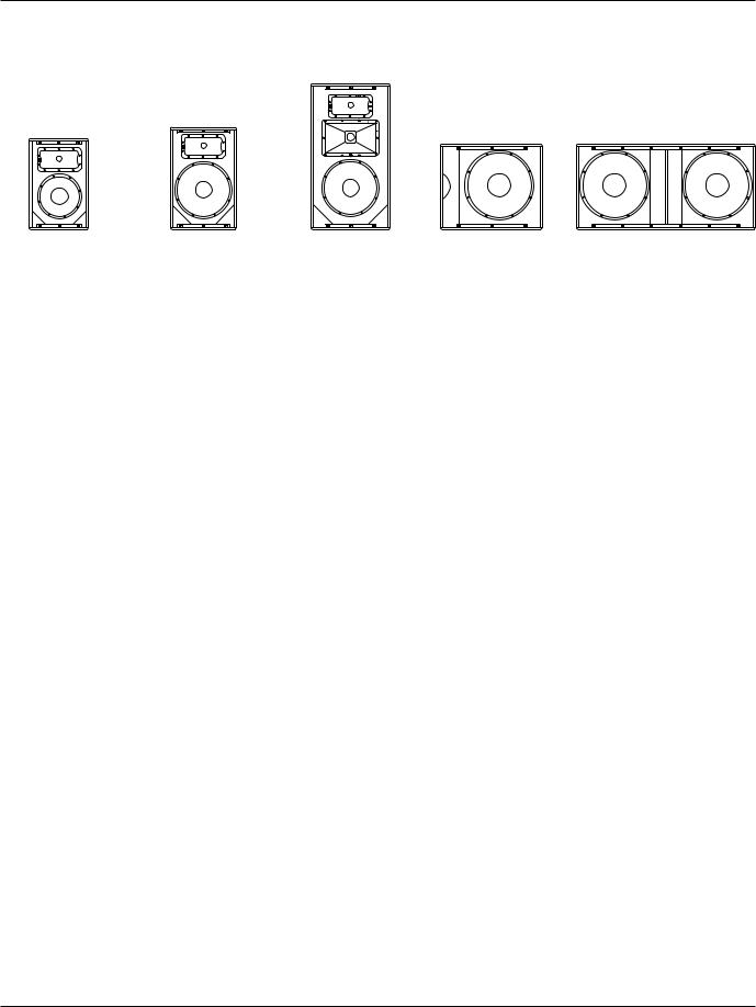
Overview - SRX800 Family
SRX812P |
SRX815P |
SRX835P |
SRX818SP |
SRX828SP |
Thank you for purchasing the new JBL SRX800!
The SRX800 Series is the next generation high performance powered loudspeaker system from JBL Professional. Comprising three full range and two subwoofers, the SRX800 boasts an array of premium features that make it the very best system in its class. Drawing on JBL’s long history of groundbreaking technology and innovative loudspeaker design, the SRX800 Series
meets the needs of the most demanding applications where high performance, comprehensive control and legendary JBL sound are required. Each component in the SRX800 Series was purposefully designed and thought through with full consideration for its intended use, each component carefully matched to achieve a perfectly tuned system that is both powerful and easy to use.
The full range 12” two-way, 15” two-way and 15” three-way systems are powered by proprietary 2,000 Watt Crown amplification. The 18” subwoofer and 18” dual subwoofer feature 1,000 and 2,000 Watt Crown amplifiers. All models integrate Crown’s Proprietary Front-End DriveCore Technology, premium JBL user-configurable DSP, including V5 Tunings compatible with our flagship Vertec and VTX touring systems, and full HiQnet Network control with Mac and PC software and standalone applications for iOS and Android. Now, local touring houses and smaller to medium installations can deploy a no-compromise, all-in-one solution configurable as a full range system with monitors and subs, either floor standing, tripod mounted, stacked, or pole mounted, and fully flyable with the SRX800’s integrated suspension points.
12
 Loading...