


SYNTHESIS
SDEC-1000/2500
INSTALLATION GUIDE

TABLE
OF
CONTENTS
SECTION ___________________________________________________________PAGE
1.0_________________________________________________________PRECAUTIONS
5.5Important Safeguards for Audio Products _________________________________________7–10
2.0_____________________________________________INTRODUCTION TO THE SDEC
2.0Introduction __________________________________________________________________________11 The Concept __________________________________________________________________________11
2.1SDEC-1000 and SDEC-2500 Rear Panels ____________________________________________________12
2.2What the SDEC does _________________________________________________________________13–17 Driver EQ ____________________________________________________________________________13 Driver Time Correction __________________________________________________________________14 Channel-to-Channel Distance Correction (Auto-Time Correction)__________________________________15 Crossovers ___________________________________________________________________________15 Screen Correction ______________________________________________________________________16 Modes_______________________________________________________________________________16 Room Correction EQ_________________________________________________________________16–17
3.0__________________________________________________INSTALLING THE SDEC
3.1Location, Location, Location . . . ___________________________________________________________18
3.2A Note On Wiring ______________________________________________________________________19
3.3Wiring Connections to the SDEC________________________________________________________20–22 Case I – Replacing an analog equalizer in an existing Synthesis system _________________________20–21 Case II – Installing an SDEC as part of a new Synthesis system installation_______________________21–22 Power the system up for the first time ______________________________________________________22
4.0_______________________________THE DIGITAL ACOUSTIC CALIBRATION SYSTEM
4.1Operational Overview ________________________________________________________________23–27 Stimulus _____________________________________________________________________________23 Data Acquisition ____________________________________________________________________23–24 Data Post-Processing ___________________________________________________________________24 Display Data __________________________________________________________________________24 Make Corrections ______________________________________________________________________25
Target Curves ______________________________________________________________________25 Ideal Low-Frequency Response __________________________________________________25–26 Ideal High-Frequency Response __________________________________________________26–27
4.2DACS4 Connections and Use __________________________________________________________28–32 Things To Consider When Selecting A Location For DACS4 ______________________________________28 Hookup ______________________________________________________________________________29 AC/Power Connections _______________________________________________________________29 Audio Connections __________________________________________________________________30 Other Connections __________________________________________________________________30 Microphone Connection and Placement _______________________________________________30–32
3
TABLE
OF
CONTENTS
SECTION ___________________________________________________________PAGE
Room Placement ________________________________________________________________30 How is the Room Used?________________________________________________________31 Microphone #1 _______________________________________________________________31 Now Place the Remaining Microphones _________________________________________31–32
4.3Power Up Synthesis and DACS4 ___________________________________________________________33
4.4Preliminary Surround Processor Settings____________________________________________________34 I. Global Settings ______________________________________________________________________34 II. Mode Specific Settings________________________________________________________________34
4.5DACS4 Operation ___________________________________________________________________35–40 Notational Conventions__________________________________________________________________35 About Online Help___________________________________________________________________35 [F-1] Help ______________________________________________________________________35 Starting DACS4________________________________________________________________________35 Initial DACS4 Screen_________________________________________________________________36 Enter Customer Information ___________________________________________________________37 Synthesis Model ____________________________________________________________________38 Select a Surround Processor __________________________________________________________38 Center Screen Compensation __________________________________________________________39 Left/Right Compensation _____________________________________________________________39 Confirm DACS4 Connections __________________________________________________________40
4.6DACS4 Main Screen _________________________________________________________________41–45 Response Graph _______________________________________________________________________42 Filters at a Glance ______________________________________________________________________42 Individual Filter Control__________________________________________________________________43 Channel and Mode Selection/Status ________________________________________________________43 Overlay Previously Tested Channels ________________________________________________________44 Online Help ___________________________________________________________________________44 Special Function Keys________________________________________________________________44–45
4.7Calibration Walk-Through _____________________________________________________________46–56 Auto-Time Correction ___________________________________________________________________47 Cinema, Subwoofer Calibration_________________________________________________________48–50 Setting the Level ____________________________________________________________________49 Auto-Equalization ___________________________________________________________________50 Cinema, Left – Center – Right Calibration _________________________________________________48–50 Setting the Level ____________________________________________________________________51 Run Auto-EQ_______________________________________________________________________52 Left and Right Ambient Calibration ______________________________________________________52–53 Setting The Level ___________________________________________________________________53 Music Mode Calibration _________________________________________________________________53
4

TABLE
OF
CONTENTS
SECTION ___________________________________________________________PAGE
Quitting DACS4________________________________________________________________________54 After A Complete Calibration __________________________________________________________54 Quitting When Some Channels Are Not Accepted___________________________________________54 SDEC Maintenance _____________________________________________________________________54 Using the Loader Utility ______________________________________________________________54 Troubleshooting ____________________________________________________________________55–56 Correcting Hum Problems ____________________________________________________________55 Why Does It Hum In The First Place?_________________________________________________55 What You Can Do During Installation _________________________________________________55 Video Devices ___________________________________________________________________56
5.0_______________________________________________________SPECIFICATIONS
5.0Specifications _________________________________________________________________________57
6.0 ___________________________________________INTERCONNECTION DIAGRAMS
Synthesis One Interconnection Diagram _____________________________________________________58–59 Synthesis Two and Three Interconnection Diagram ____________________________________________60–61
7.0 ____________________________________________CONTROL WIRING DIAGRAMS
Synthesis One Control Wiring Diagram______________________________________________________62–63 Synthesis Two and Three Control Wiring Diagram _____________________________________________64–65
8.0__________________________________________SYNTHESIS LIMITED WARRANTY
6.0Synthesis Limited Warranty ______________________________________________________________66
JBL Synthesis SDEC-1000/2500
Installation Guide
©1998 Harman Digital Systems Group
“Dolby” and “Pro Logic” are trademarks of Dolby Laboratories. Confidential Unpublished Works. ©1992–1997
Dolby Laboratories, Inc. All Rights Reserved THX is a registered trademark of Lucasfilm, Ltd.
JBL and Synthesis are registered trademarks of JBL Incorporated. All Rights Reserved
Design and digital production by Harman Digital Systems Group Design and Production Center, Woodbury, New York
JBL Consumer Products
250 Crossways Park Drive, Woodbury, NY 11797
8500 Balboa Boulevard, Northridge, CA 91329
800-336-4JBL
Printed on Recycled Paper
Part Number: 1113-SDECInstal
5
TABLE
OF
Figures
Figure 1: Raw Driver Response/Corrected Driver Response _________________________________________13 Figure 2: System With & Without Driver Time Correction___________________________________________14 Figure 3: Effect of Auto-Time Correction ________________________________________________________15 Figure 4: Effect of Screen Correction EQ ________________________________________________________16 Figure 5: Effect of Room EQ _________________________________________________________________17 Figure 6: System Response In 5 Locations ______________________________________________________26 Figure 7: Synthesis 1 Main Target Curve, Below 1kHz______________________________________________28 Figure 8: Complete Synthesis 1 Target Curve ____________________________________________________29 Figure 9: DACS4 Connection to Synthesis_______________________________________________________31 Figure 10: Microphone Placement: Large Listening Area ____________________________________________33 Figure 11: DACS4 Opening Screen _____________________________________________________________37 Figure 12: Customer Information Window _______________________________________________________38 Figure 13: Customer Information Window: Select A Synthesis Model___________________________________39 Figure 14: Select A Surround Processor _________________________________________________________39 Figure 15: Identify Screen Type, Center Channel ___________________________________________________40 Figure 16: Identify Screen Type, Left & Right Front_________________________________________________40 Figure 17: DACS4 On Screen Wiring Diagram_____________________________________________________41 Figure 18: DACS4 Main Calibration Screen _______________________________________________________42 Figure 19: Response Graph Window____________________________________________________________43 Figure 20: Filter Setting and Control Field ________________________________________________________43 Figure 21: Filter Control Field _________________________________________________________________44 Figure 22: Direct Channel and Mode Access ______________________________________________________44 Figure 23: Channel Display Control Field_________________________________________________________45 Figure 24: Continuously Updated Online Help_____________________________________________________45 Figure 25: Function Keys and Status Line ________________________________________________________45 Figure 26: Channel Gain and Delay Information ___________________________________________________46 Figure 27: Fresh Install, First Screen____________________________________________________________47 Figure 28: Auto-Time Correction Dialog Box ______________________________________________________48 Figure 29: Ready For Subwoofer Level Test ______________________________________________________49 Figure 30: Setting Level______________________________________________________________________50 Figure 31: Without Smoothing Filter ____________________________________________________________50 Figure 32: Results of Auto-EQ_________________________________________________________________51 Figure 33: Left Cinema Level Set_______________________________________________________________52 Figure 34: Auto-EQ _________________________________________________________________________53 Figure 35: Ambient Target ____________________________________________________________________54
6

1.1
IMPORTANT SAFEGUARDS
1.1 Important Safeguards
For Audio Products
PLEASE READ CAREFULLY ALL THE FOLLOWING IMPORTANT SAFEGUARDS THAT ARE APPLICABLE TO YOUR EQUIPMENT
1.Read Instructions – All the safety and operating instructions should be read before the product
is operated.
2.Retain Instructions – The safety and operating instructions should be retained for future reference.
3.Heed Warnings – All warnings on the product and in the operating instructions should be adhered to.
4.Follow Instructions – All operating and use instructions should be followed.
5.Water and Moisture – The product should not be used near water – for example, near a bathtub, washbowl, kitchen sink, laundry tub, in a wet basement, or near a swimming pool, and the like.
6.Carts and Stands – The product should be used only if a cart or stand is recommended by the manufacturer.
6a. A product and cart combination should be moved with care. Quick stops, excessive force, and uneven surfaces may cause the product and cart combination to overturn.
7.Wall or Ceiling Mounting – The product should be mounted on a wall or ceiling only when and as recommended by the manufacturer.
8.Ventilation – The product should be situated
so that its location or position does not interfere with its proper ventilation. For example, the product should not be situated on a bed, sofa, rug, or similar surface that may block the ventilation openings; or placed in a built-in installation, such as a bookcase or cabinet, that may impede the flow of air through the ventilation openings.
PRECAUTIONS1.0
9.Heat – The product should be situated away
from heat sources such as radiators, heat registers, stoves, or other products that produce heat. If placed near an amplifier, check with the manufacturer for applicability.
10.Power Sources – The product should be connected to a power supply only of the type described in the operating instructions or as marked on the product.
11.Grounding or Polarization – Precautions should be taken so that the grounding or polarization means of a product is not defeated.
12.Power-Cord Protection – Power-supply cords should be routed so that they are not likely to be walked on or pinched by items placed upon or against them, paying particular attention to cords at plugs, convenience receptacles, and the point where they exit from the product.
13.Cleaning – The product should be cleaned only as recommended by the manufacturer.
14.Power Lines – An outdoor antenna should be located away from power lines.
CAUTION: TO PREVENT ELECTRIC SHOCK, DO NOT USE THIS (POLARIZED) PLUG WITH AN EXTENSION CORD RECEPTACLE OR OTHER OUTLET UNLESS THE BLADES CAN BE FULLY INSERTED TO PREVENT BLADE EXPOSURE.
ATTENTION: POUR PREVENIR LES CHOCS ELECTRIQUES NE PAS UTILISER AVEC UN PROLONGATEUR. UNE PRISE DE COURANT OU UNE AUTRE SORTIE DE COURANT SAUF SI LES LAMES PEUVENT ETRE INSEREES A FOND SANS EN LAISSER AUCUNE PARTIE A DECOUVERT.
CAUTION |
RISK OF ELECTRIC SHOCK |
DO NOT OPEN |
CAUTION: TO REDUCE THE RISK OF ELECTRIC SHOCK, DO NOT REMOVE COVER (OR BACK). NO USER-SERVICEABLE PARTS INSIDE. REFER SERVICING TO QUALIFIED SERVICE PERSONAL.
|
The lightning flash with arrowhead |
|
The exclamation point within an |
|
symbol, within an equilateral trian- |
|
equilateral triangle is intended to |
|
gle, is intended to alert the user to |
|
alert the user to the presence of |
|
the presence of uninsulated ”dan- |
|
important operating and mainte- |
|
gerous voltage” within the product's |
|
nance (servicing) instructions in |
enclosure that may be of sufficient magnitude to |
|
|
|
the literature accompanying the unit.. |
|||
constitute a risk of electric shock to persons. |
|
|
|
WARNING: TO REDUCE THE RISK OF FIRE OR ELECTRIC SHOCK, DO NOT EXPOSE THIS UNIT TO RAIN OR MOISTURE.
7
1.1
IMPORTANT SAFEGUARDS
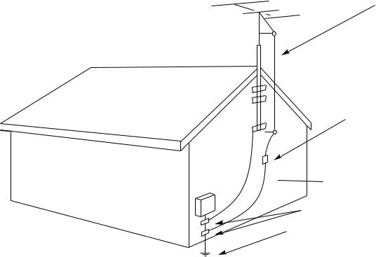
ANTENNA
LEAD-IN
WIRE
Example of Antenna Grounding as per National Electrical Code
ANTENNA DISCHARGE UNIT (NEC SECTION 810-20)
 GROUNDING CONDUCTORS
  (NEC SECTION 810-21)
GROUND CLAMPS
POWER SERVICE GROUNDING ELECTRODE SYSTEM
(NEC ART 250, PART H)
15.Nonuse Periods – The power cord of the product should be unplugged from the outlet when left unused for a long period of time.
16.Object and Liquid Entry – Care should be taken so that the objects do not fall and liquids are not spilled into the enclosure through the openings.
17.Outdoor Antenna Grounding – If an outside antenna is connected to the receiver, be sure the antenna system is grounded so as to provide some protection against voltage surges and built-up static charges. Article 810 of the National Electrical Code, ANSI/NFPA 70, provides information with regard to proper grounding of the mast and supporting structure, grounding of the lead-in wire to an antenna-discharge unit, size of grounding conductors, location of antenna-discharge unit, connection to grounding electrodes, and requirements for the grounding electrode (see above figure).
18.Damage Requiring Service – The
product should be serviced by qualified service personnel when:
a.The power supply or the plug has been damaged; or
b.Objects have fallen on, or liquid has been spilled into, the product; or
c.The product has been exposed to rain; or
d.The product does not appear to operate normally or exhibits a marked change in performance; or
e.The product has been dropped, or the enclosure damaged.
19.Servicing – The user should not attempt to service the product beyond what is described in the operating instructions. All other servicing should be referred to qualified service personnel.
Note To CATV System Installer:
This reminder is provided to call the CATV system installer’s attention to Article 820-22 of the NEC that provides guidelines for proper grounding and, in particular, specifies that the cable ground shall be connected to the grounding system of the building, as close to the point of cable entry as practical.
8

Deutsch
Wichtige Sicherheitsanweisungen
Heben Sie sich diese Sicherheitsanweisungen auch für später auf.
Befolgen Sie alle auf der Vorrichtung stehenden Anweisungen und Warnungen.
Immer nur mit der richtigen Spannung verwenden! Die Gebrauchsanweisungen des Herstellers informieren Sie über die elektrischen Anforderungen. Vergessen Sie nicht daß bei vershiedenen Betrievsspannungen ggf. auch verschiedene Leitungskabel und/oder Verbindungsstacker zu verwenden sind.
Stellen Sie die Vorrightung nicht in ein unbelüftetes Getell oder unmittelbar über wärmeerzeugende Geräte wie z.B. Tonverstärker. Halten Sie die in den Produktspezifikationen angegebene maximale Umgebungstemperatur bei Betrieb ein.
Schlitze und Öffnungen im GehUause dienen der Belüfung; um verläßlichen Betrieb sicherzustellen und Überheizen zu vermeiden dürfen diese Öffnungen nich verstopft oder abgedeckt werden. Stecken Sie nie irgend einen Gegenstand durch die Belüftungsschlitze. Vergießen Sie keine Flüssigkeiten auf den Apparat.
Dieses Produkt is mit einem 3-drahtigen Erdungsstecher ausgerüstet. Diese Sicherheitsmaßnahme darf nicht unwirksam gemacht werden.
Schließen Sie nie Tonverstärker unmittelbar an einen Anschluß des Apparates an.
Um elektrischen Schlag oder Feuer zu vermeiden, setaen Sie den Apparat weder Regen noch Feuchtigkeit aus und betreiben Sie ihn nicht dort wo Wasser eindringen könnte.
Versuchen Sie nicht den Apparat zu betreiben falls er fallen gelassen, beschädigt, oder Flüssigkeiten ausgesetzt wurde, oder falls sich seine Arbeitsweise derart ändert daß daraus ein Bedarf nach Raparatur zu schließen ist.
Dieser Apparat sollte nur von qualifizierten Fachleuten geöffnet werden. Das Abnehmen von Abdeckungen setzt Sie gefährlichen Spannungen aus.
Dieses Dreick auf ihrem Apparat warnt Sie voe nicht-isolierter, gefährlicher Spannung im Gehäuse…stark genug um eine Berührungsgefahr darzustellen.
Diese Dreick auf ihram Apparat bedeutet daß wichtige Betriebsund Wartungsanweisungen in der mitgelieferten Dokumentation zu finden sind.
Français
Instructions de Sûreté Importantes
Gardex ces instructions pour réference future.
Observez toutes les instructions et tous les avertissements marqués sur l’appareil.
Branchez uniguements sur un réseau de tension indiquée. Consultez le manuel d’instruction du fabriquant pour les spécifications de courant. N’oubliez pas que différentes tensions peuvent nécessiter l’utilisation de cables et/ou de fiches deconnexion différents.
N’installez pas l’appareil en un compartiment non-aéré ou directement au-dessus d’équipements générateurs de chaleur, tels qu’amplificateurs de courants, etc. Ne dépassez pas la température ambiante maximale de fonctionnement indiquée dans les spécifications du produit.
Des fentes et ouvertures sont prévues dans le boîtier pour l’aération; Pour assurer le bon fonctionnement et pour prévenir l’échauffement, ces ouvertures ne doivent pas être couvertes ou bloquées. N’insérez pas d’objets dans les fentes d’aération. Empêchez tout liquide de se répandre sur l’appareil.
Ce produit est muni d’une fiche à trois fils pour la mise à terreee. Ceci est une mesure de sécurité et ne doit pas être contrariée.
Ne connectez jamais d’amplificateurs audio directement aux connecteurs de l’appareil.
Pour empêcher les chocs électriques et le danger d’incendie, évitez d’exposer l’appareil à la pluie ou à l’humidité, et ne le mettez pas en marche en un endroit où il serait exposé aux éclaboussures d’eau.
N’essayez pas de faire fonctionner l’appareil s’il est tombé à terre, a été endommangé, exposé à un liquide, ou si vous observez des différences nettes dans son fonctionnement, indiquant la nécessité de réparations.
Cet appareil ne doit être ouvert que par un personnel de service qualifié. En enlevant les couvercles vous vous exposez àdes tensions électriques dangereuses.
Ce triangle, sur votre appaeil vous avertit de la présence de tension dangereuse, non-isolée à l’intérieur du boîtier…une tension suffisante pour représenter un danger d’electrocution.
Ce triangle sur sur votre appareil vous invite de suivre d’importantes instructions d’utillisation et d’entretien dans la documentation livrée avec le produit.
Español
Instrucciones importantes de sequiridad
Guarde esta instrucciones para uso posterior.
Utilice siempre el voltaje correcto. Diríjase a las instrucciones de operación del fabricante para obtener las especificaciones de potencia. Esté al tanto de que voltajes de operación distintos requieren el uso de cable y/o enchufes distintos.
No instale esta unidad en un estante sin vntilación, ni tampoco directamente encima de equipose que generen calor tales como amplificadores de potencia. Fíjese en las temperaturas ambientales máximas de operación que se mencionan en las especificaciones del producto.
Las aperturas y ranuras del chasis sirven para proveer la ventilación necesaria para operar la unidad con sequridad y para prevenir sobrecalentamiento, y por lo tanto no pueden ser obstruidas o cubiertas. No introcuzca objetos de ningún tip a través de las ranuras de ventilación, y nunca deje caer ningún líquido sobre
la unidad.
Este producto está equipado con un enchufe de 3 clavijas con conexión a ierra. Este es un elemento de seguridad que no debe ser eliminado.
Nunca conecte ningùn tipo de salida de amplificadores de sonido directamente a los conectores de la unidad.
Para prevenir descargas eléctricas o incendios, mantenga la unidad alejada de la lluvia, humedad o cualquier lugar en el que pueda entrar en contacto con ague.
No trate de hacer funcionar la unidad si se ha caído, está dañada, ha entrado en contacto con lítuidos, o si nota cualquir cambio brusco en su funcionamiento que indique la necesidad de hacerle un servicio de mantenimiento.
Esta unidad deberá ser abierta únicamente por personal calificado. Si usted quita las coberturas se expondrá a voltajes peligrosos.
Este triángulo que apaece en su componente le advierte sobre la existencia dentro del chasis de voltajes peligrosos sin aislantes…voltajes que son lo suficientemente grandes como para causar electrocución.
Este triángulo que aparece en su componente lo alerta sobre las instrucciones de operación y mantenimiento importantes que están en los materiales de lectura que se incluyen.
Italiano
Importanti norme di sicurezza
Conservare le presenti norme per l’utilizzo futuro.
Osservare tutte le istruzioni e le avvertenze apposte sull’unita.
Utilizzare esclusivamente con la tensione di rete corretta. Consultare le istruzioni operative fornite dal fabbricante per i dati riguardanti la tensione e l’assorbimento di corrente. Potrebbe essere necessario l’uso di cavi di rete e/o di spine diverse a seconda della tensione utilizzata.
Non installare l’unità in uno scaffale privo di ventilazione oppure direttamente sopra una fonte di calore, come, ad esempio, un amplificatore. Non superare la temperatura ambientale massima di funzionamento riportata nei dati tecnici del prodotto.
Le fessure e le altre aperture nella scatola servono alla ventilazione. Per un funzionamento affidabile, e per evitare un eventuale surriscaldamento, queste aperture non vanno ostruite o coperte in nessun modo. Evitare in tutti i casi di inserire oggetti di qualsiasi genere attraverso le fessure di ventilazione. Non versare mai del liquido di nessun tipo sull’unità.
Questo pordotto viene fornito con una spina a 3 fili con massa. Tale dispositivo di sicurezza non va leiminato.
Evitare sempre di collegare le uscite dell’amplificatore auio direttamente ai connettori dell’unità.
Per prevenire il pericolo di folgorazione e di incendio non esporre l’unità alla pioggia o ad un’umidtà eccessiva; evitare di adoperare l’unità dove potrebbe entrare in contatto con acqua.
Evitare di adoperare l’unità se la stessa è stata urtata violentemente, se ha subito un danno, se è stata esposta ad un liquido o in caso di un evidente cambiamento dell prestazioni che indichi la necessità di un intervento di assistenza tecnica.
Ogni intervnto sull’unità va esqguito esclusivamente da personale qualificato. La rimozione della copertura comporta l’esposizione al pericolo di folgorazione.
ll present triangolo impresso sul componente avverte della presenza di tensioni pericolose non isolate all’interno della copertura…tali tensioni rappresentano un pericolo di folgorazione
ll presente triangolo imprsso sul componente avverte l’utente della presenza nella documentazione allegata di importanti istruzioni relative al funzionament ed alla manutenzione.

Dansk
Vigtig information om sikkerhed
Gem denne vejledning til senere brug.
Følg all anvisninger og advaresler på apparatet.
Apparatet skal altid tilslttes den korrekte spænding. Der henvises til brugsanvisningen, der indeholder specifikationer for strømforsyning. Der gøres opmærksom på, at ved varierende driftsspændinger kan det blive nødvendigt at bruge andre ledningsog/eller stiktyper.
Apparated må ikke monteres i et kabinet uden ventilation eller lige over andet udstyr, der udvikler varme, f.eks. forstærkere. Den maksimale omgivelsestemperatur ved drift, der står opført i specifikationerne, skal overholdes.
Der er ventilationsåbninger i kainettet. For at sikre apparatets drift og hindre overophidning må disse åbninger ikke blokeres elle tildækkes. Stik aldrig noget ind igennem ventilationsåbningerne, og pas på aldrig at spilde nogen form for væske på apparatet.
Dette apparat er forsynet med et stik med jordforbindelse. Denne sikkerhedsforanstaltning må aldrig omgås.
Udgangsstik fra audioforstærkere må aldrig sættes direkte i apparartet.
Apparatet må ikke udsættes for regn eller fugt og må ikke bruges i nærheden af vand for at undgå risiko for elektrisk stød og brand.
Apparatet må aldrig bruges, hvis det er blevet stødt, beskadiget eller vadt, eller hvis ændringer i ydelsen typer på, at det trænger til eftersyn.
Fette apparat må kun åbnes af fagfolk, Hvis dækslet tages af, udsættes man for livsfarlig højspænding.
Denne mærkat på komponenten advarer om uisoleret, farlig spænding i apparatet… høj nok til at give elektrisk stød.
Denne mærkat på komponenten advarer om vigtig driftsog vedligeholdsinformation i den tilhørende litteratur.
Suomi
Tärkeitä varten
Säilytä nämä ohjeet tulevaa käyttoöä varten.
Seuraa kaikkia yksikköön merkittyjä ohjeita ja varoituksia.
Käytä aina oikeaa verkkojännitettä. Tehovaatimukset selviävät valmistajan käyttöohjjeista. Huomaa, että eri käyttöjännitteet saattavat vaatia toisenlaisen verkkojohdon ja/taipistokkeen käytön.
Älä asenna yksikköä telineeseen jossa ei ole tuulet usta, tai välittömästi lämpöä tuottavien laitteiden, esim. tehovahvistimien, yläpuolelle. Ympäristön Iämpötila käytössä ei saa ylittää twotespesifikaation maksimilämpötilaa.
Kotelo on varustettu tuuletusreiillä ja -aukiooa. Luotettavan toiminnan varmistamisksi ja ylilämiseksi näitä aukkoja ei saa sulkea tai peittää. Mitään esineitä ei saa työntää tuuletusaukkoihin. Mitään nestritä ei saa kaataa yksikköön.
Tuote on varustettu 3-jjohtimisella maadoitetulla verkkipistokkeella. Tämä on turvallisuustoiminne eikä sitä saa poistaa.
Älä kytke audiotehovahvistimen lähtöjä suoraan mihinkään yksikön liittimeen.
Sähköiskun ja palovaaran välttämiseksi yksikkö ei saa olla sateessa tai kosteassa, eikä sitä saa käyttää märässä ympäristössa.
Älä käytä yksikköä jos se on pudonnut, vaurioitunut, kostunut, tai jos sen suorituskkyky on huomattavasti muuttunut, maikä vaatii huoltoa.
Yksikön saa avata vain laitteeseen perehtynyt huoltohenkilö. Kansien poisto altistaa sinut vaarallisille jännittelille.
Tämä kolmio, joka esiintyy homponentissasi, varoittaa siua eristämättömän vaarallisen jännitteen esiintymisestä yksikön sisällä. Tämä jännite saattaa olla riittävä korkea aiheuttamaan sähköiskuvaaran.
Tämä koimio, joka esiintyy komponentissasi, kertoo sinulle, että tässä tuotedokumentoinnissa esiintyy tärkeitä käyttö-ja ylläpite-ohjeita.
Norsk
Viktig informasjon om sikkerhet
Ta vare pådenne veiledningen for senere bruk.
Følg alle anvisningene og advarslene som er angitt på apparatet.
Apparatet skal alltid anvendes med korrekt spenning.
Produktbeskrivelsen inneholder spesifikasjoner for strømkraav. Vær oppmerksom på at det ved ulike driftsspenninger kan være nødvendig å bruke en annen ledningog/eller støpseltype.
Apparatet skai ikke monteres i skap uten ventilasjon, eller direkte over varmeproduserende utstyr, som for eksempel kraftforsterkere. Den maksimale romtemperaturen som står oppgitt i produktbeskrivelsen, skal overholdes.
Apparatet er utstyrt med ventilasjonsåpninger. For at apparatet skal være pålitelig i bruk og ikke overopphetes, må disse åpningene ikke blikkeres eller tildekkes. Stikk aldri noe inn i ventilasjonsåpningene, og pass på at det aldri søles noen form for væske på apparatet.
Dette apparatet er utstyrt med et jordet støpsel. Dette er en sikkerhetsforanstaltning som ikke må forandres.
Utgangsplugger fra audioforsterkere skai aldri koples direkte til apparatet.
Unngå brannfare og elektrisk støt ved å sørge for at apparatet ikke utsettes for regn eller fuktighet og ikke anvendes i næheten an vann.
Apparatet skal ikke brukes hvis det har blitt utsatt for støt, er skadet eller blitt vått, eller hvis endringer i ytelsen tyder på at det trenger service.
Dette apparatet skal kun åpnes av fagfolk. Hvis dekselet fjernes, utsettes man for livsfarlig høyspenning.
Komponenten er merket med denne trekanten, som er en advarsel om at det finnes uisolert, farlig spenning inne i kabinettet…høy nok til å utgjøre en fare for elektrisk støt.
Komponenten er merket med denne trkanten, som betyr at den tilhørende litteraturen inneholder viktige opplysninger om drift og vedikehold.
Svenska
Viktiga säkerhetsföreskrifter
Spara dess föreskrifter för framtida bruk.
Följ alla anvisningar och varningar som anges på engeten.
Använd alltid rätt nätspänning. Se tillverkarens bruksanvisningar för information om effektkrav. Märkväl, att andra matningsspänningar eventuellt kräver att en annan typs nätsladd och/eller kontakt anänds.
Installera inte enheten i ett oventilerat stativ, eller direkt ovanför utrustningar som avger värme, t ex effektförstärkare. Se till att omgivningens temperatur vid drift inte överskrider det angivna värdet i produktspecifikationen.
Behållaren är försedd med hål och öppningar för ventilering. För att garantera tillförlitlig funktion och förhindra överhettning får dessa oppningar inte blockeras eller täckas. Inga föremål får skuffas in genom ventilationshålen. Inga vätskor får spillas på enheten.
Produkten är försedd med en jordad 3-trådskontakt. Detta ä en säkerhetsfunktion som inte får tas ur bruk.
Anslut aldrig audioeffektförstärkarutgångar direkt till någon av enhetens kontakter.
För att undvika elstöt eller brandfara får eenheten inte utsättas för reegn eller fukt, eller användas på ställen där den blir våt.
Använd inte enheten om den far fallit i golbet, skadats, blivit våt, eller om dess prestanda förändrats märkbart, vilket kräver service.
Enheten får öppnas endast av behörig servicepersonal. Farliga spänningar blir tillgängliga när locken tas bort.
Denna triangel, som visas på din komponent, varnar dig om en oisolerad farlig spänning inne i engeten. Denna spänning är eventuellt så hög att fara för elstöt föreligger.
Denna triangel, som visas på din komponent, anger att viktiga bruksanvisningar och servideanvisningar ingår i dokumentationen i fråga.
10
2.0
INTRODUCTION 2.0
INTRODUCTION
JBL Synthesis SDEC-1000/ SDEC-2500 Installation Guide:
The SDEC-1000/2500 is a dealer installed digital equalizer and time correction unit. It is part of the Synthesis home theater package. This Installation Guide will supply all the necessary information for the operation of the SDEC-1000 with Synthesis 1, or the SDEC-2500 with Synthesis 2 and 3.
Introduction:
From its inception, JBL Synthesis has been the answer to the questions: “How do you build a state-of-the-art home theater system and make it sound superb in every installation? How can you be sure all the hardware is compatible?” These were the big questions five years ago – Synthesis was the answer.
Once again, JBL Synthesis moves beyond the competition and is the answer. The JBL Synthesis Digital Equalizer (SDEC) is a six channel in/seven channel out 20-bit digital audio signal processor. Unlike nearly all other audio components on the market, the SDEC has been designed to work specifically with other Synthesis System components. This narrow application focus has allowed our engineers to design a product with far fewer compromises, resulting in unequalled system performance. By reading the following pages, you will become familiar with the technological features and unique capabilities incorporated within the SDEC and available nowhere else.
The Concept:
Visualize a speaker system with the highest performance components available. Imagine that you have the power of 20-bit digital signal processing available to correct any remaining system non-linearity. Fantasize about crossovers that are theoretically perfect, and time-domain correction delivering idealized impulse response.
The fun doesn’t stop there. Now that this perfected speaker is in the room, you’ve got arrival time correction, multipositional spatially averaged measurements and scientifically derived target response curves for each speaker, multiband parametric equalizers, auto-EQ algorithms and compensation for perforated video projection screens! How good would all this be? In a few words, “very, very good”!
Okay, stop dreaming. It’s here, now. (It’s in that box over there, and you’re going to install it and make someone very happy!) The JBL Synthesis Solution™. The SDEC and the Digital Acoustic Calibration System (DACS) together can achieve what others only dream about.
Properly used, a high-quality equalizer can improve the overall sound quality of most systems. However, there are many areas of a speaker’s behavior that can be improved, but only if you know, in advance, what the speaker needs. The Synthesis solution allows this to be a reality. Until now, anything beyond the most basic equalization has been impossible without expensive acoustical instrumentation and the knowledge to use it. This is why, traditionally, equalizers have been general-purpose devices, designed to be applicable to any audio system, usually of doing more harm than good!
Add to this situation the fact that equalizing a speaker system by ear is truly a futile exercise. This helps to account for the generally low acceptance of equalizers outside of professional audio applications.
11
2.1
SDEC-1000 REAR PANEL SDEC-2500 REAR PANEL
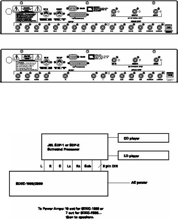
SDEC-1000 Rear Panel
SDEC-2500 Rear Panel
System connection after dealer installation and calibration.
12

2.2
WHAT THE SDEC DOES
The SDEC, available in two models that differ only slightly in function, is a digital signal processor capable of performing several functions simultaneously. In general, the device is fed signals from the surround processor (the Synthesis SDP-1, 2 or 2D) that have been separated into discrete left, center, and right front channels, side and/or rear surround signals, and subwoofer/lfe (low-frequency effects) signals.
By converting these six signals into digital bitstreams, and feeding them into a DSP (digital signal processing) engine using extremely powerful Motorola processors, the signals can be manipulated in the digital domain to achieve several desired results.
Driver correction, arrival time manipulation, room correction, and frequency division are some of the tricks easily done by what amounts to a powerful, special-purpose computer, but which would require inordinate complexity (and would result in signal-quality degradation) if done in the analog domain. After processing, high-quality digital-to-analog converters return the signals to the analog domain, and pass them on to Synthesis amplifiers.
What the SDEC does:
Driver EQ:
The drivers used in Synthesis systems are designed and manufactured to reproduce both music and the audio associated with cinema as faithfully as possible. But real-world mechanisms, however well crafted, have limitations imposed on their operation due to the nature of available materials and the inescapable laws of physics. Because the SDEC is used only in Synthesis systems and, therefore, is only used with a small number of different drivers, programs can be loaded into it to smooth out response irregularities, compensate for manufacturing tolerances, etc. Tell the system during installation whether it’s a Synthesis I, II, or III and corrections, programmed at the factory by JBL engineers, are instantly applied to make very good drivers sound even better.
Figure 1:
Raw Driver Response/Corrected Driver Response
13
2.2
WHAT THE SDEC DOES
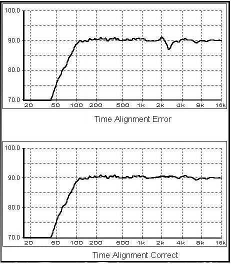
Driver Time Correction:
Once again, because the SDEC “knows” what speakers it’s being used with, it can correct for the different arrival times of sounds from lowand high-frequency drivers. Arrival times are slightly different because the horns, tweeters, and midrange drivers are mounted at somewhat different distances from the listener. The SDEC can delay the sound coming from the closer drivers slightly, so that all frequencies impinge on the listener’s ears simultaneously, reducing acoustic “smear”. All the frequency components that comprise complex waveforms arrive together; the end result is greater fidelity to the original waveshape.
Figure 2:
System With and Without Driver Time Correction
14

2.2
WHAT THE SDEC DOES
Channel to Channel Distance Correction (Auto-Time Correction):
The listener’s preferred listening location doesn’t always coincide with the “acoustically best” position; furniture placement, screen location, traffic patterns and other factors can keep us from sitting where “sound sounds best”, typically determined by speaker placement geometry. The SDEC can compensate for unequal distances to loudspeakers and move the “sweet spot” to the listener. This feature is called “Auto-time arrival correction” in the Synthesis system.
Figure 3:
Effect of Auto-Time Correction
Crossovers:
The SDEC-1000 (used in bi-amplified Synthesis I systems) performs the function of electronic crossover in addition to its other tasks. This allows for more precise transducer correction and all other attendant advantages of bi-amplification. The crossovers are 24dB per octave (4th order) Linkwitz-Riley type. This high-performance class of filter is rarely attempted in passive crossover designs due to its inherent complexity.
15

2.2
WHAT THE SDEC DOES
Screen Correction:
The computational power of the SDEC allows it to compensate for the effects of placing the front center channel loudspeaker behind any of several popular types of projection perforated screen material.
Figure 4:
Effect of Screen Correction EQ
Modes:
Although not a major consideration before the advent of home theater, inherent differences exist between an idealized music-only and an idealized cinema sound reproduction system. Cinema sound is produced with using
theater speakers that employ horn-loaded compression drivers. The directivity-index of horn-loaded drivers is significantly different from that of direct radiator designs. The best way to reproduce cinema audio is with speakers that exhibit similar directivity characteristics.
Synthesis systems employ horn-loaded drivers for cinema and direct radiators for music.
The SDEC contains two sets of equalization curves selected by the system controller for each of the Synthesis I, II, and III systems. Sources identified by the SDP-2 or the more recent DTS-equipped SDP-2D as music-only are fed through conventional midrange cone drivers and dome tweeters; theatrical audio is automatically fed to horn-based transducers, and equalization is changed to the appropriate settings.
Room Correction EQ:
The parameter (or, more accurately, set of parameters) more responsible for overall sound quality than almost any other is the acoustic signature, or characteristics, of the listening environment. Absolute room dimensions, the ratio of the room dimensions, the shape of the room, absorption/reflection characteristics of the walls, and room furnishings can make
the most expensive equipment sound mediocre or enhance the sound of mediocre equipment. In this area, the SDEC is
16

2.2
WHAT THE SDEC DOES
nothing less than magic! With 90 available bands of parametric equalization (each adjustable for center frequency, amount of boost or cut, and bandwidth (the reciprocal of Q), its ability to address the specific problems of a given environment is far beyond any graphic equalizer. Typically, such devices are two-edged swords, able to cause at least as many problems as they solve. In this case, however, a preprogrammed computer, using proprietary algorithms developed over a period of several years by JBL, guides the automatic adjustment process, transforming acoustic torture chambers into acoustically superior environments. The essential ingredient necessary for success is knowledge of what can and cannot be corrected with equalization.
Figure 5:
Effect of Room EQ
17
3.1 |
3.0 |
|
LOCATION, LOCATION, LOCATION ... |
||
INSTALLING THE SDEC |
||
|
Location, location, location…
(Please note that this installation guide assumes a U.S. location, in which the power source is 120 volt, 60Hz. JBL can supply the SDEC for use in 230 volt, 50Hz environments on special order. Contact JBL for details and delivery information.)
Pick a location, determined by the relationship to other equipment and power availability. Note that there are NO user controls on the SDEC: it need NOT be located where the user can easily reach it. Once programmed, it is turned On AND Off by trigger signals from the Synthesis SDP-1, 2 or 2D, and, in turn, triggers the power amplifiers on and off. It can be located close to the surround processor/decoder or close to the power amplifiers, although it should NOT be subject to the heat they generate. For this reason, it may be better to locate it near the surround processor.
To simplify the following discussion, it will be assumed that the surround processor/decoder is a Synthesis SDP-2D, although it may be an earlier SDP-1 or SDP-2. The SDP-1 is a Dolby® Pro Logic® decoder and control system, while the SDP-2 incorporates the ability to decode AC-3® signals from DVD players or laser disc players equipped with RF demodulators, such as the Synthesis SDP-RFD. The SDP-2D, the newest addition to the Synthesis family of controller/ processors, adds DTS decoding capability, while retaining AC-3 and Pro-Logic modes of operation. In subsequent discussion, the word “controller” will be used to indicate the SDP-1, 2 or 2D, or whatever alternate equipment is being used to select input sources and control power to ”downstream” pieces of signal processing equipment.
Frequently, the SDEC will be retrofitted to a Synthesis system previously equipped with an analog equalizer. It can be mounted in place of the old equalizer and mode switching equipment, and will require considerably less space. A minor amount of rewiring will be necessary. This is covered in CASE I, below. CASE II covers new installations of Synthesis systems.
18
3.2
A NOTE ON WIRING
A note on wiring:
There are four types of wiring systems associated with all Synthesis systems:
•Signal wiring: RCA-to-RCA type interconnects will serve to route analog audio signals between the surround processor, the SDEC and the power amplifiers. Only high-performance interconnects should be used. A pre-fabricated set of cables is provided with the SDEC. Any additional interconnects added to the system should be of equal or greater quality to ensure trouble-free operation.
•Speaker wiring: Only high-performance, heavy gage speaker wire should be used. Any wire-runs through or within walls must conform to local flammability requirements and be appropriately marked; CL-3 is one example of such a rating. Refer to the Synthesis S-400/S-650 Power Amplifier User’s Manual for more information about selecting appropriate speaker wires.
•AC power: It is recommended that the system be connected to a dedicated 20-amp AC circuit. If this is not an option, try to avoid using an AC circuit that is shared with heavy appliances. Never connect any Synthesis equipment into a switched outlet. Removing the AC power while the system is ON will cause no permanent damage, but may lock up its microprocessors, necessitating turning the system fully off, then on again. It may also cause loud pops and clicks in the loudspeakers.
•Control lines: All Synthesis components communicate with one another via a standard DIN connection cable. This cable enables automatic power an mode switching of the entire system from the surround processor.
19
 Loading...