

Janome 1600P, 1600-DB, 1600-DBX Servicing Manual
Servicing Manual
1600P, 1600-DB &1600-DBX

Replacing the External Parts
Face plate .................................................................................................... 1
Top Cover .....................................................................................................1
Belt Cover ....................................................................................................1
Motor Cover .................................................................................................1
Base ............................................................................................................. 1
Mechanical Adjustment
Needle Bar Height ........................................................................................ 2
Presser Bar Height .......................................................................................2
Feed Dog Height ..........................................................................................3
Feed Dog Alignment .................................................................................... 3
Feed Cam Timing.........................................................................................4
Feed Lifting Cam Timing ..............................................................................5
Needle to Hook Timing................................................................................. 6
Clearance between Needle and Hook Point ................................................6
Hook Stopper Position ................................................................................. 7
Bobbin Winder Stopper ................................................................................8
Check Spring Stroke ....................................................................................9
Pretension Dial ............................................................................................. 9
Knee Lifter Lever ........................................................................................ 10
Needle Stop Position.................................................................................. 11
Needle Threader (1600P only) ................................................................... 12
Replacing the Electronic Components
Location of the Electronic Components .....................................................13
Location of the Connectors ........................................................................14
Internal Wiring ............................................................................................15
Circuit Board-A ........................................................................................... 16
Circuit Board-F and Slide Volume ..............................................................16
Driving Motor ........................................................................................ 17-18
Power Transformer ..................................................................................... 19
Machine Socket .......................................................................................... 19
Light Bulb ................................................................................................... 20
Adjustment of the Thread Cutter Mechanism
(1600P and 1600-DBX only)
Static Cutter Blade .....................................................................................21
Thread Cutter Blade................................................................................... 22
Thread Guide Plate .................................................................................... 23
Needle to Cutter Cam Timing..................................................................... 24
Thread Drawing Lever ................................................................................25
Auto Tension Release ................................................................................ 26
Thread Cutter Troubleshooting................................................................... 27
Table of Contents
1
Replacing the External Parts
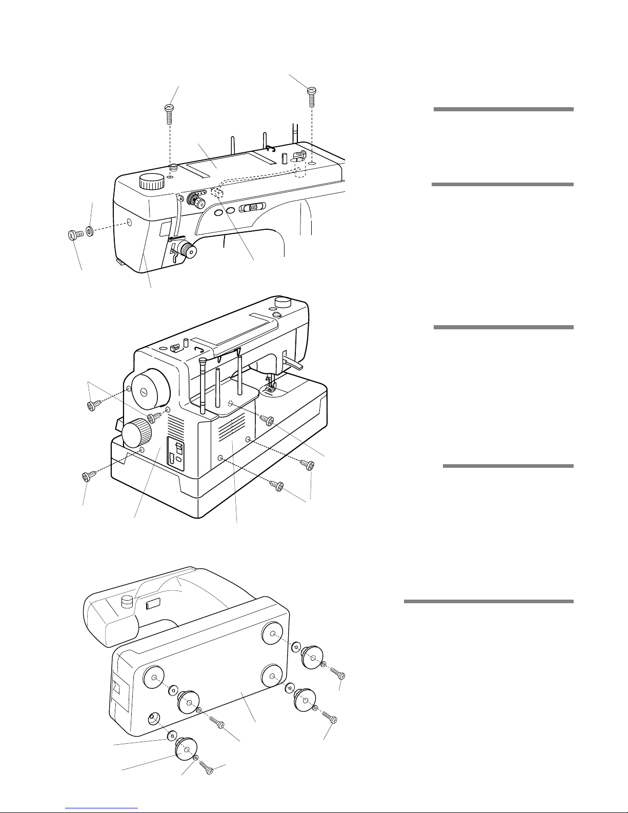
1. Face Plate
2. Top Cover
3. Belt Cover
4. Motor Cover
5. Base
Remove the setscrew (1) and washer (2). Remove the face plate (3).
Remove the 2 setscrews (4).
Lift the top cover (5) and pull out the motor
connector (6). Remove the top cover.
Remove the 3 setscrews (7) and remove the belt
cover (8).
NOTE:
When attaching the belt cover, engage the hooks
with the motor cover.
Remove the 3 setscrews (9) and remove the
motor cover (10).
Remove the 4 hinge screws (11), washers (12),
rubber feet (13) and base washers (14). Remove
the base (15).
(1)
(2)
(3)
(4)
(4)
(5)
(6)
(7)
(7)
(8)
(10)
(9)
(9)
(11)
(15)
(11)
(11)
(11)
(12)
(13)
Follow the above procedures in reverse.
To attach:
To remove:
(14)
2
Mechanical Adjustment
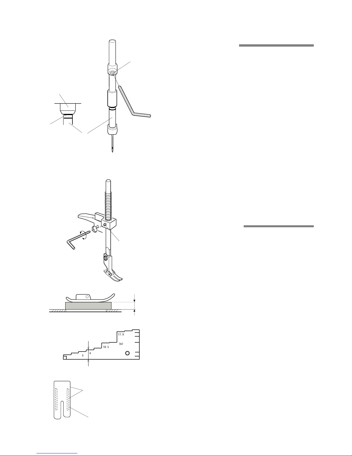
1. Needle Bar Height
2. Presser Bar Height
[1] Remove the face plate.
[2] Turn the handwheel to bring the needle bar (1) to the
lowest position.
[3] Loosen the setscrew (2). Move the needle bar (1) up
or down and match the upper hairline (3) with the
bottom edge of the needle bar bushing (4).
NOTE:
Be sure not to rotate the needle bar when adjusting the
needle bar height. The needle clamp screw should be
parallel to the upper shaft.
[4] Tighten the setscrew and attach the face plate.
(1)
(3)
(4)
(2)
The distance between the bottom of the presser foot in
up position and the needle plate should be 5.7 - 6.3 mm.
[1] Remove the face plate and needle.
[2] Lower the feed dog below the needle plate. Place a
block 6 mm thick under the presser foot and lower
thepresser foot lifter.
(Use the 4th step from the left of the Gauge 767G-
001).
[3] Loosen the setscrew (1). Raise the presser foot lifter
while holding presser bar. Tighten the setscrew (1)
firmly.
Attach the needle and face plate.
NOTE:
Make sure that the presser foot should be parallel to the
feed dog slots (2) in the needle plate and that the needle
does not touch the presser foot.
6 mm
(1)
(2)
Presser foot should be parallel
to the feed dog slots.
6mm
3
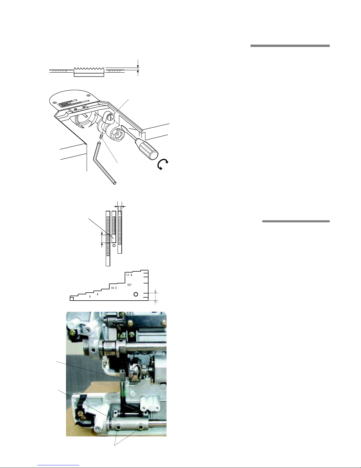
3. Feed Dog Height
When the feed dog is fully raised the height should be
0.8 - 1.0 mm above the needle plate.
[1] Set the stitch length dial at 6 (Maximum). Turn the
hand wheel to bring the feed dog to the highest
position.
[2] Loosen the setscrew (1).
[3] Turn the eccentric pin (2) to adjust the feed dog height
to 0.9 mm.
- If the feed dog is too low, turn the pin to the right (3).
- If the feed dog is too high, turn the pin to the left (4).
[4] Tighten the setscrew (1).
0.8 - 1.0
mm
(1)
(3)
(4)
(2)
4. Feed Dog Alignment
The lateral gaps between both sides of feed dogs and
needle plate slots should be even.
The clearance between the front end of the center feed
dog and center slot should be 4.2 - 4.8 mm when the
stitch length dial is set at 0.
[1] Remove the base and lay the machine on its back.
[2] Set the stitch length dial at 0.
[3] Loosen the setscrews (1). Move the feed base (2) up
or down to adjust the clearance (3) between the front
end of the center feed dog and center slot to 4.5 mm.
(Use the marking on the Gauge 767G-001). Adjust the
lateral position of the feed dogs by moving the feed
rock shaft (4) to the right or left if necessary.
[4] Tighten the setscrews (1). Set the stitch length dial
at 6 and turn the handwheel to check if the feed dogs
do not touch the needle plate.
[5] Attach the base.
(1)
(3)
(4)
(2)
Lateral gaps should be even.
4.2 - 4.8
mm
4.5 mm
4
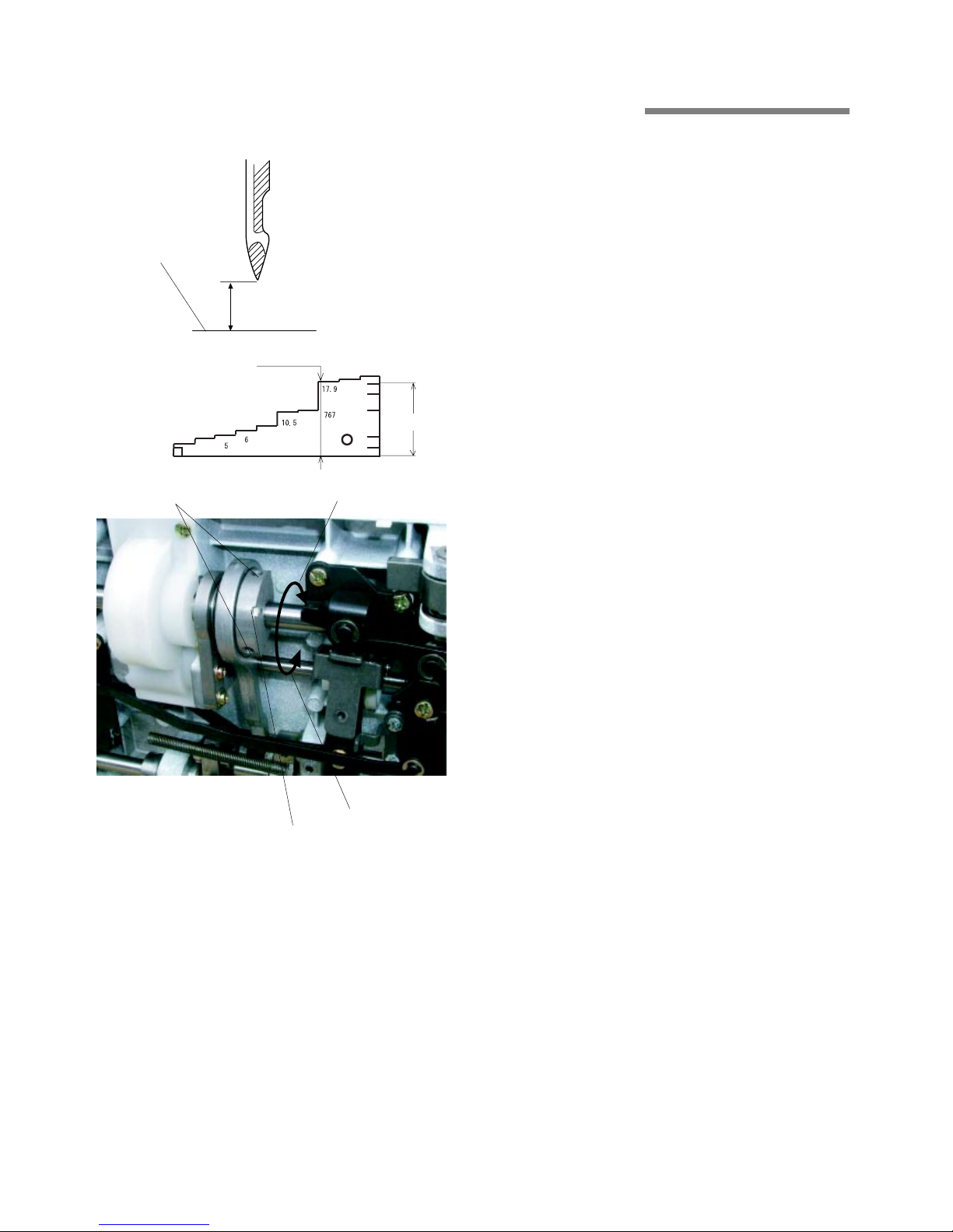
5. Feed Cam Timing
To Check:
[1] Lower the needle bar by turning the handwheel until
the point of the needle is 17.9 mm (for 1600P-DB/
DBX) or 17.5 mm (for 1600P) above the upper
surface of the needle plate (1).
[2] The feed dogs should not move when moving the
reverse stitch lever up and down.
If the feed dogs move, adjust the feed cam timing as
follows.
To Adjust:
[1] Remove the base and lay the machine on its back.
[2] Lower the needle bar until the needle point is 17.9
mm (for 1600P-DB/DBX) or 17.5 mm (for 1600P)
above the needle plate (1).
(Use the third step from the right for 17.9 mm or the
marking for 17.5 mm on the Gauge 767G-001).
[3] Loosen the setscrews (2).
While moving the reverse stitch lever, turn the feed
cam (3) in the direction either A or B until the feed
dogs stop moving.
[4] Tighten the setscrews (2) and attach the base.
(1)
(3)
(2)
A
B
17.9 mm (1600P-DB/DBX)
17.5 mm (1600P)
17.9 mm
17.5 mm
5
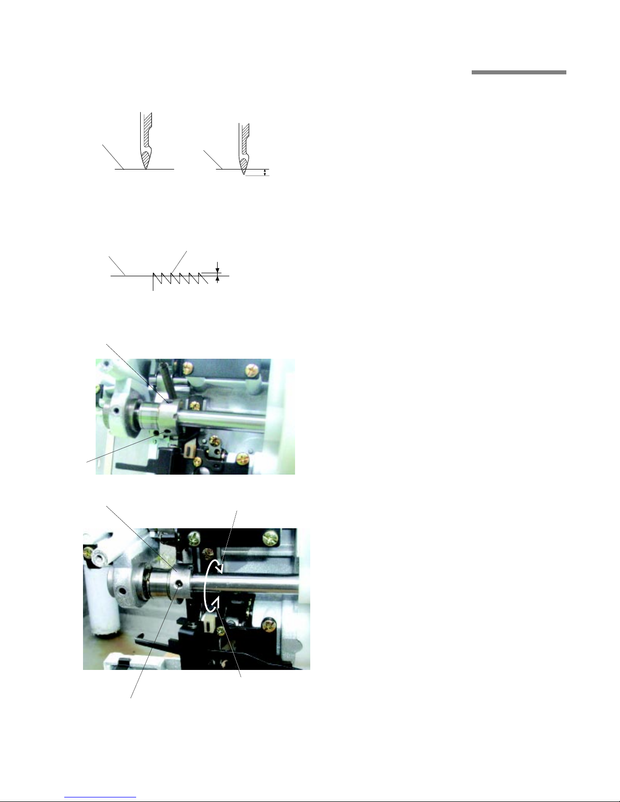
6. Feed Lifting Cam Timing
To check:
[1] Lower the needle bar until the point of needle is level
with the upper surface of the needle plate (1) (1600PDB/DBX) or 0.4 mm below the needle plate (1600P).
[2] The top of the feed dogs (2) should be 0 - 0.1 mm
above the needle plate.
To adjust:
[1] Remove the base and lay the machine on its back.
* You may set the stitch length dial at any position.
[2] Loosen the setscrew (3).
Lower the needle bar until the needle point is level
with the needle plate (1)(1600P-DB/DBX) or 0.4 mm
below the needle plate (1600P).
[3] Loosen the setscrew (4).
[4] If the feed dogs are higher, turn the feed lifting cam
(5) in the direction A.
If the feed dogs are lower, turn the feed lifting cam (5)
in the direction B.
[5] Tighten the setscrew (3) and attach the base.
(1)
(4)
(2)
(1)
(1)
(5)
A
B
0.4 mm
0 - 0.1 mm
1600P-DB/DBX
1600P
(3)
(4)
6
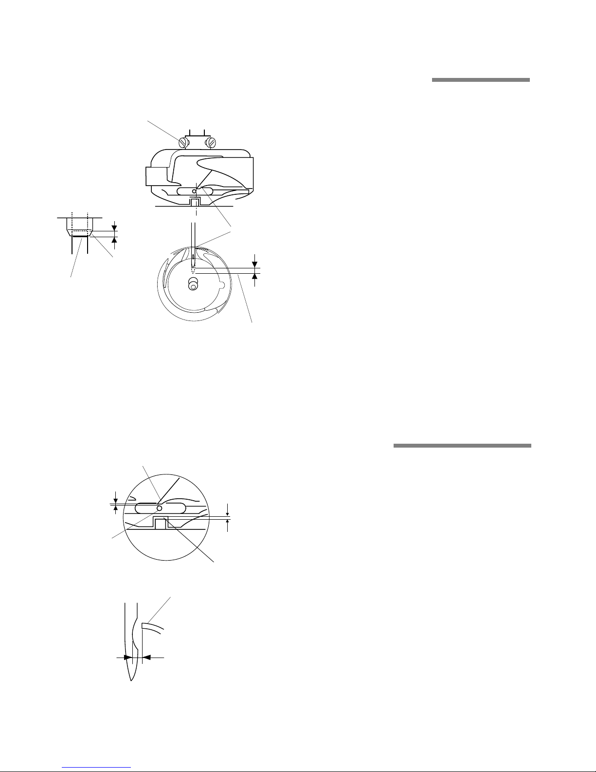
7. Needle to Hook Timing
8. Clearance between Needle
and Hook Point
[1] Remove the needle plate.
[2] Loosen the 3 setscrews (1). Pull out the hook race
very slightly (less than 0.5 mm).
[3] Raise the needle bar from the lowest position until the
lower hairline (2) of the needle bar matches the edge
of the needle bar bushing (3).
NOTE:
The needle bar rises 2 mm from the lowest position.
[4] Rotate the hook to match the hook point (4) with the
right side of the needle.
[5] Tighten the setscrews (1) slightly and proceed with
the adjustment of the clearance between the needle
and hook point.
(4)
(1)
(2)
(3)
Lowest position
2 mm
2 mm
The clearance between the needle and hook point
should be 0 - 0.1 mm.
[1] Turn the handwheel to bring the hook point (1) behind
the needle (2).
[2] Knock on the hook race rim lightly to make a slight
clearance between the needle and hook point.
NOTE:
Do not knock on the hook body.
[3] Tighten the setscrews firmly and check the needle to
hook timing and the thread path (3) (0.4 - 0.8 mm). If
not, replace the hook race stopper with new one.
(There is no way to adjust.)
[4] Attach the needle plate.
(1)
(2)
(1)
0 - 0.1
mm
0 - 0.1
mm
0.4 - 0.8 mm
(3)
7
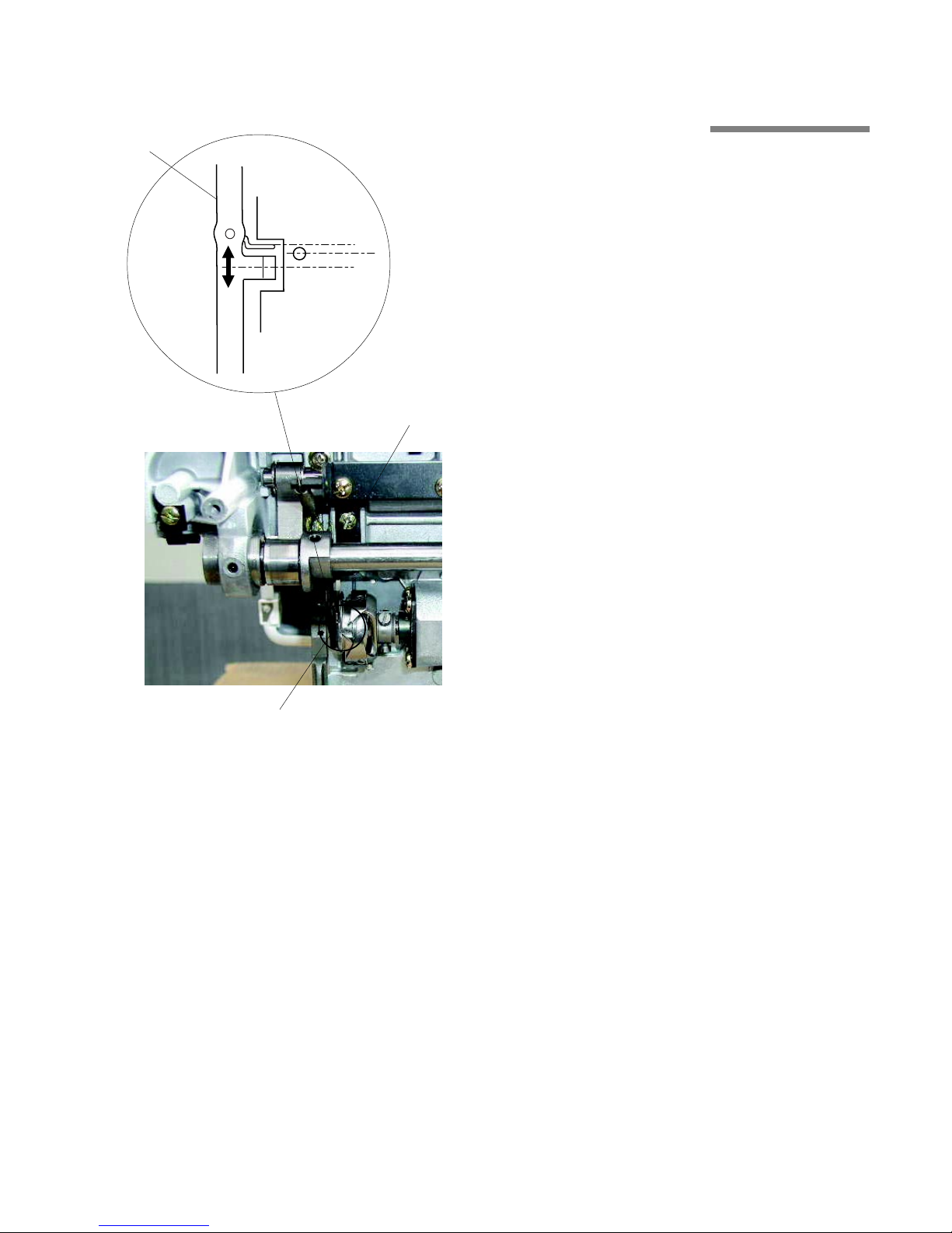
9. Hook Stopper Position
[1] Remove the base, needle plate and feed dog.
[2] Loosen the setscrew (1) and move the hook stopper
(2) so that the center of the needle (3) is located
between the center of the hook stopper (4) and outer
side of the hook stopper spring (5).
[3] Tighten the setscrew (1) and attach the feed dog,
needle plate and base.
(1)
(2)
(3)
(5)
(4)
(2)
 Loading...