


AVD4.6
User Guide
2
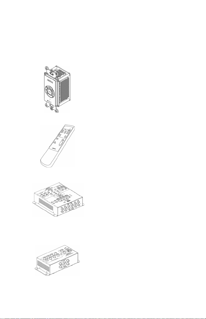
Component overview
KP4.6
Wall mounted keypad in each zone.
Can be used in both main and subzones.
RC4.6
Basic system remote control. Can
control same functions as KP4.6.
AM4.6
Audio module. Located next to the
source equipment and distributes 2
channel audio to all zones.
VM4.6 (optional)
Video module. Located next to the
source equipment and distributes
video to all zones.

Congratulations
Congratulations on your new Jamo AVD4.6 distribution
system.
The many different options and features of your new audio and video*
distribution system will be a source of pleasure for you for many years to
come.
The Jamo AVD4.6 system is a distributed, multi-room home entertainment system capable of delivering high quality audio and video to multiple rooms and locations in your home.
After it is installed, you have access to all your centrally located audio
and video equipment through stylish wall-mounted control panels or
remote controls from each location with a control panel installed. Sound
is delivered to in-wall or ceiling speakers (or conventional speakers if
preferred) and video is delivered to televisions or monitors.
*Video distribution requires the optional VM4.6 module installed.
3
Content
Component overview
KP4.6 wall control unit
RC4.6 system remote control
System details
Limited warranty
2
4
5
6+7
7
4
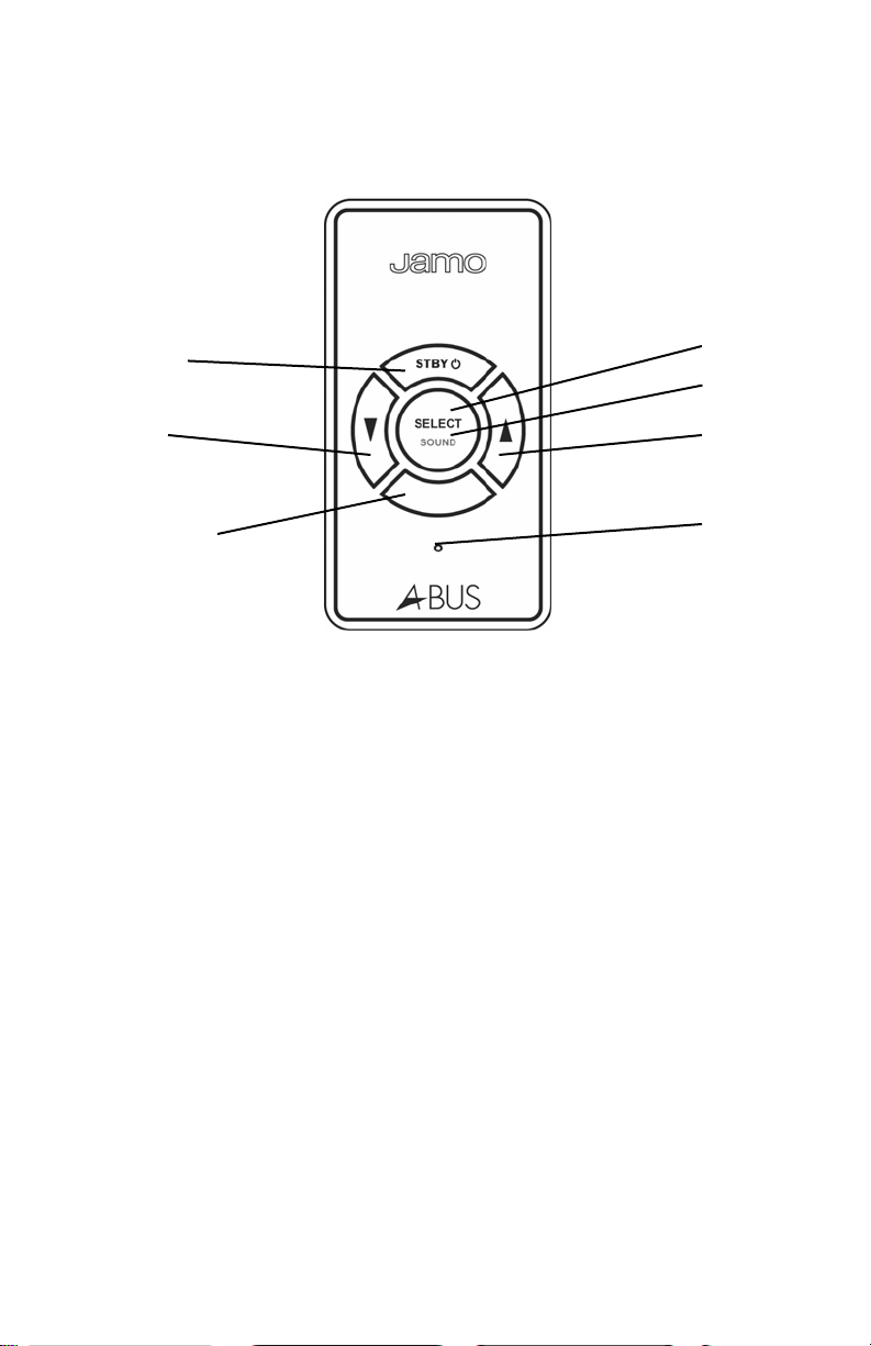
KP4.6 wall module
Standby
Select
Sound
Down
IR win-
Up
Status
Standby Short push to turn keypad/system on.
Short push to turn keypad off.
Long push (approx. 2 sec.) to turn system off (ALL OFF)*
Down Adjusts volume, bass and treble down
Adjusts balance to left and fader to sub-woofer/amplifier
IR Window Receives signals from remote controls
Blinks red to indicate signal received
Select Short push to change source*
Sound Long push to enter Sound Adjustment functions (page 5)
Up Adjusts volume, bass and treble up
Adjusts balance to right and fader to main speakers
LED Keypad on: Solid green
Keypad off: Off
Keypad in mute: Blinks green
Adjusting volume or sound: Blinks orange
End points on volume or sound: Blinks red
Change source: Blinks twice for each push
Sound adjustment functions: Blinks red
*Only in Jamo enhanced A-BUS mode. See page 5 of AVD4.6 Installation Guide.
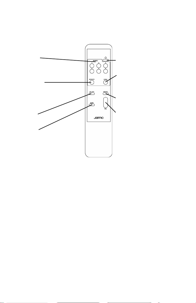
RC4.6 remote control
5
Source
Turns the keypad/system
on and selects source 1 - 6
to be played
EXT/CCTV
Turns the keypad/system
on and selects additional
source (e.a. CCTV) if installed
All off
Turns system off
Standby
Turns the keypad off
Local
Turns the keypad/system on
and selects local input if installed (avail. spring 2005)
Select
Enters Sound Adjustments
Volume
See page 4
Mute
Mutes the keypad
Volume adjustment
The LED blinks orange when adjusting volume up and down. When
reaching full volume the LED blinks red. When reaching minimum volume (Mute) the LED blinks green.
Sound adjustments
To enter Sound Adjustments push and hold Sound (4 sec.) to reach the
desired function. The LED blinks red once for Bass, twice for Treble, three
times for Balance and four times for Fader. If still held it will return to Bass
and cycle through again. Start to adjust the desired function within 2 sec.
or the system goes back to volume adjustment (LED green).
When adjusting Bass, Treble, Balance and Fader the LED blinks orange.
The led blinks red when reaching the top or bottom end and blinks
green at the mid point (no adjustment to sound).
If no adjustment is made the system will automatically go back to volume adjustment (LED green) after 2 sec.

6
System details
Main zone/room details Sub zone/room details
1 ______________________ _____________________
2 ______________________ _____________________
3 ______________________ _____________________
4 ______________________ _____________________
5 ______________________ _____________________
6 ______________________ _____________________
7 ______________________ _____________________
8 ______________________ _____________________
9 ______________________ _____________________
10 ______________________ _____________________
11 ______________________ _____________________
12 ______________________ _____________________
13 ______________________ _____________________
14 ______________________ _____________________
15 ______________________ _____________________
16 ______________________ _____________________
AM4.6 Serial No/s. ________________________________
VM4.6 Serial No/s. ________________________________

System details
Source equipment details
Source 1 ______________________________________
Source 2 ______________________________________
Source 3 ______________________________________
Source 4 ______________________________________
Source 5 ______________________________________
Source 6 ______________________________________
7
Limited Warranty
Jamo loudspeakers and accessories are covered by a limited warranty in
respect to manufacturing and equipment defects. Other claims are not
covered. This warranty is a national warranty in accordance with relevant
legislation. Period of the warranty is as stated below and is in effect from
the date of purchase.
Customer sales slip with date of purchase is the only document needed
for warranty claims.
Jamo warranty on all loudspeakers and accessories is seven (7) years except in-wall and in-ceiling loudspeakers, which carry Limited Lifetime
Warranty. Electronics (receivers, amplifiers, screens, distribution systems,
sub-woofer amplifier etc.) carries a two (2) year warranty.
For a complete Statement of Limited Warranty see page 11 in the
AVD4.6 Installation Guide.

www.jamo.com

AVD4.6
1

Important safety information
Before installing cables or the Jamo AVD4.6 system it is important that you check and comply with all building
regulations or codes applicable to your area. If you are in any doubt contact your local building regulations/code offi ce
and/or seek professional advice.
Read instructions - All the safety and operating instructions should be read before the AVD4.6 system is operated.
Keep instructions - The safety and operation instructions should be kept for future reference.
Heed warnings - All warnings on the product and the operating instructions should be adhered to.
Follow instructions - All operating and use instructions should be followed.
Cleaning - Unplug all system components from the wall outlet before cleaning any part of the system. Do not use liquid cleaners
or aerosol cleaners. Use a damp cloth for cleaning.
Attachments - Do not use attachments which are not recommended by the manufacturer as they may cause hazards.
Water and moisture - Do not install the AVD4.6 modules and power supply near water, for example, near a bath tub or sink; in a
wet basement, or near a swimming pool etc.
Accessories - Do not install any part of the system on an unstable surface, stand, bracket or table. The product may fall, causing
serious injury to a child or adult, and may damage the product. Any mounting of the product should follow the manufacturer’s
instructions, and should use a mounting accessory if recommended by the manufacturer.
Ventilation - Slots and openings in cabinets/enclosures are provided for ventilation and to ensure reliable operation of the product and to protect them from overheating. These openings must not be blocked or covered. The openings should never be blocked
by placing the product on a soft surface. The AM4.6 should not be placed in a built-in installation such as a bookcase or rack unless
proper ventilation is provided and the manufacturer’s instructions have been adhered to. For all components, the manufacturers
instructions on ventilation must be adhered to.
Power Sources - The PS24 or PS 4.6 should be operated only from the type of power source indicated on the marking label.
If you are not sure of the type of power supply to your home, consult your product dealer or local power company.
Grounding or Polarization - In some countries the PS24 or PS4.6 may be equipped with a polarized mains plug (a plug having one
pin wider than the other). This plug will fi t into the power outlet only one way. This is a safety feature. If you are unable to insert the
plug into the outlet, try reversing the plug. If the plug still does not fi t, contact your electrician to replace your obsolete outlet. Do
not defeat the safety purpose of the polarized plug.
Power-Cord Protection - Power cords should be routed so that they are not likely to be walked on or pinched by items placed
upon or against them, paying particular attention to cords at plugs, mains sockets/outlets, and the point where they exit from the
product.
Protective Attachment Plug - In some countries product may be equipped with a plug having overload protection (fuse). This is
a safety feature. If replacement of the plug is required, be sure the service technician has used a replacement plug specifi ed by the
manufacturer that has the same overload protection as the original plug.
Lightning - For added protection for this product during a lightning storm, or when it is left unattended and unused for long periods of time, unplug it from the wall outlet. This will prevent damage to the product due to lightning or power-line surges.
Overloading - Do not overload wall outlets, extension cords, or integral mains sockets/outlets as this can result in a risk of fi re or
electric shock.
Object and Liquid Entry - Never push objects of any kind into this product through openings as they may touch dangerous voltage points or short-out parts that could result in a fi re or electric shock. Never spill liquid of any kind on the product.
Servicing - Do not attempt to service this product yourself as opening or removing covers may expose you to dangerous
voltage or other hazards. Refer all servicing to an authorized service agent.
Damage Requiring Service - Refer any part of this system requiring service to an authorized Jamo service agent only.
Heat - The product should be situated away from heat sources such as radiators, heat registers, stoves, or other products
2

Contents
Important safety information 2
Planning your system 4
Pre-installation 5
Audio connections 6
Video connections 7
Linking modules 8
Advanced system connections 9
System specifications 10
FAQs 11
Limited warranty 11
Congratulations on your new Jamo AVD4.6 distribution system.
The many different options and features of your new audio and video* distribution system will be a source of
pleasure for you for many years to come. The Jamo AVD4.6 system is a distributed, multi-room home entertainment
system capable of delivering high quality audio and video to multiple rooms and locations in
your home. After it is installed, you have access to all your centrally located audio and video equipment through
stylish wall-mounted control panels or remote controls from each location with a control panel installed. Sound is
delivered to in-wall or ceiling
speakers (or conventional speakers if preferred) and video is delivered to televisions or monitors.
*Video distribution requires the optional VM4.6 module installed.
3

Planning your system
Detailed advanced planning should be done before installing the AVD4.6 system. It is therefore strongly recommended that the complete instructions are read before starting any installation.
KP4.6
KP4.6
KP4.6
KP4.6
KP4.6
KP4.6
AM4.6
KP4.6
KP4.6
KP4.6
Fig. 1
AM4.6
The main module (AM4.6) should be located close to the source components. This gives two location options.
1. Locate the AM4.6 and source components in a convenient location with adequate ventilation such as a closet,
utility room, cabinet or other. Fig.1.
2. It is possible to feed the signal from source equipment through the AM4.6 to existing hi-fi or surround amplifier
while at the same time distributing the signal to the rest of the home. This is done by connecting the source equipment to the AM4.6 and take the signal from the six Loop Out sockets to the amplifier/receiver in the system.
For this configuration the AM4.6 should be located behind the existing system.
The AM4.6 can be mounted either horizontally or vertically. It is powered by the dedicated power supply PS24 or
PS4.6. Try to use the same mains outlet to power both the AM4.6 and the source equipment.
VM4.6
The VM4.6 video switching module works together with the AM4.6 to send video signals to all connected zones via
RG6 or other coaxial cables. Up to 6 video sources and a CCTV may be connected and distributed.
Video source equipment can be routed from the six Loop Out socket on the VM4.6 to the receiver in a home theater
system using phono/RCA cables designed for video use. Both AM4.6 and VM4.6 can therefore be added into an
existing system. The VM4.6 can be mounted horizontally or vertically and power is provided via a CAT5e cable from
the AM4.6.
KP4.6
Each zone is controlled by a KP4.6 wall unit. They should be located in a convenient location in each zone. Fig. 1.
A KP4.6 can be used as either a main zone or a sub-zone controller. A sub-zone must listen to/watch the same source
as the main zone it is associated with, however it has independent volume, bass, treble, balance and fader adjustments. The KP4.6 has a line level pre-amp output for connection of an extra amplifier if needed in a zone, or to connect an active subwoofer in that zone. See the manual supplied with the KP4.6 for complete installation instructions.
CCTV Connection
A CCTV camera can be connected to your Multi-Room distribution system. See page 9 for details. Extra cables will be
required in addition to the listed cables under the pre-installation phase.
4
Pre-installation
Please read all of these instructions before mounting any products or installing any wires and cables.
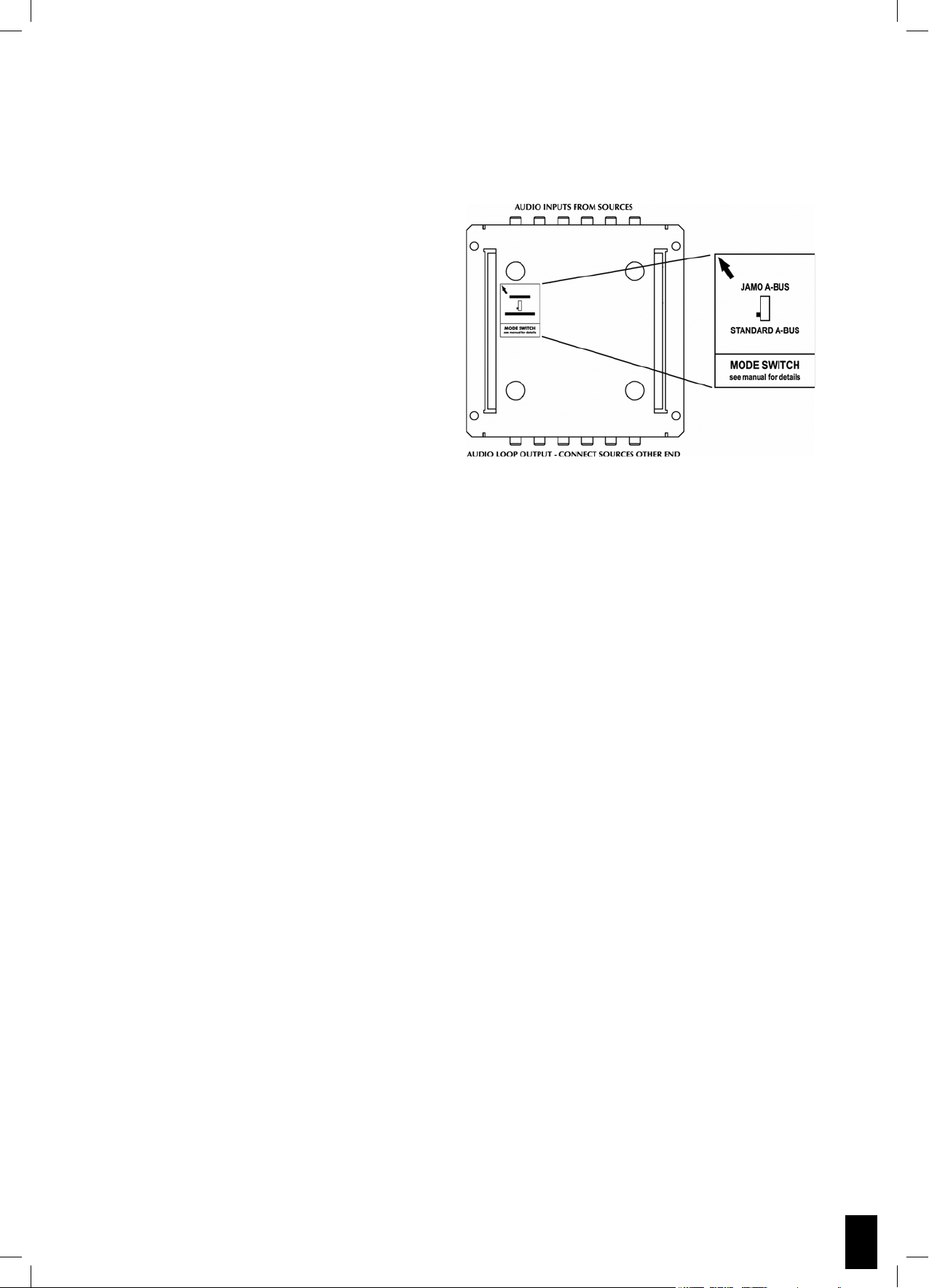
AM4.6
IMPORTANT. The AM4.6 can be switched between
Jamo A-BUS® or standard A-BUS® mode. The Jamo
A-BUS® position is used with the Jamo KP4.6 keypad
and gives extra functions. When used with other ABUS keypads it should be set to Standard A-BUS® or
they will not work. The switch is located on the rear
of the AM4.6.
The AM4.6 should be mounted on a hard surface. Do
not mount on a carpeted surface as this may limit the
airflow through the unit. It should be located within
10 feet from a power outlet.
It should not be located close to any product or installation which produces excessive electrical noise
as these could interfere with the AM4.6. These could
be dimmer racks etc.
A-BUS® is a registered trademark of LeisureTech Electronics Pty Ltd
VM4.6
Install the VM4.6 within 15 feet from the AM4.6. The same surface instructions as the AM4.6 should be followed as well
as the consideration of electrical noise sources.
Wiring and Cabling
Install a single-gang 2” or deeper J box or a P ring at each KP4.6 location. If using a J box all knock outs must be removed to provide ventilation.
Run a CAT5e cable from the AM4.6 to each KP4.6 location.
Run two speaker wires from the KP4.6 location to the speaker locations for that zone.
For video distribution (optional) run RG6 or other coaxial cable from the VM4.6 to the TV/Monitor location. It can be
terminated directly to the TV/Monitor or to a suitable wall plate fitted with a co-axial connector.
CAT5e cables should be run through conduits whenever possible, however when not available or practical special
care should be taken not to install the cable close to sharp edges and avoid risk of kinking or trapping. Do not over
tighten cable ties. Similar precaution should be taken to installation of speaker wires.
Make sure and re-check that the color code on the CAT5e cable connections are correct.
KP4.6
The KP4.6 should be located around 55” off the floor and 10-15” from door frames or wall edges, taking into account
the location of light switches etc. It should not be located where exposed to direct sunlight as this can interfere with
the infra-red sensor.
The KP4.6 should be installed in a single-gang 2” or deeper J box or in a P ring.
The CAT5e cable is connected to the KP4.6 at the color coded 8-way screw terminal on the rear.
Speaker wires are connected to screw terminals on the rear of the KP4.6.
See the manual supplied with the KP4.6 for complete installation instructions.
5

Audio connections
Audio Source Connections
It is possible to connect a total of six audio source components to the AM4.6. The connections are made from a line
level output on the source equipment to one of the six inputs on the AM4.6 using RCA to RCA cables.
Jamo emitter(s)
AM4.6
Audio Connection(s)
RCA - RCA cables
Fig. 2
Source equipment
Remote control
The source equipment can be remote controlled from all main and subzones with the remote control supplied with
the source equipment.
An IR emitter is used for each source component. The IR emitter is plugged in to the appropriate IR output on the
AM4.6 and the emitter itself is stuck onto the source equipment in front of the receiving sensor.
The ALL COMMANDS sends remote signals from any remote control, and not only from the remote control associated
with the source selected.
Two Jamo IF5 emitters are included with the AVD4.6 system.
Speakers
Sub-zone
Speakers
Main zone
KP4.6
Cat5e
PS24 or PS4.6
Sub-zones
(if installed)
PS24 or PS4.6 to AM4.6
Each AM4.6 requires one PS24 or PS4.6 for the
four main zones. In addition it needs another
PS24 or PS4.6 if any sub-zones are connected.
Fig. 2.
KP4.6 to AM4.6
Each KP4.6 is connected to the AM4.6 using a
CAT5e cable. It is plugged in to the AM4.6 using
an RJ45 plug, and connected to the KP4.6 via a
8-way color coded screw terminal.
Main zones and sub-zones are determined by
PS24 or PS4.6
Main zones
choosing a main zone or sub-zone socket on
the AM4.6.
KP4.6 to Loudspeakers
AM4.6
Fig. 3
6
Use a pair of high-quality speakercable to connect the KP4.6 to any pair of in-wall, ceiling or
other suitable speakers.
See the manual supplied with the KP4.6 for complete installation instructions.

Video connections
Video Source Connection
A total of six video sources may be connected to the VM4.6.
The video output of the source equipment is connected to the RCA sockets on the VM4.6 labeled video inputs 1-6.
Use quality 75 ohm coaxial cable with RCA plugs in each end. The control signals are sent over the CAT5e cable as
described below
Cat5e
VM4.6
Video Connection(s)
RCA - RCA cables
AM4.6
Fig. 4
Source equipment
TV/Monitor Connection
If video distribution is also part of the system the VM4.6 is connected to the AM4.6 with a CAT5e cable.
The CAT5e cable is connected at both ends with an RJ45 plug to the expansion sockets. This provides power to the
VM4.6 and input switching commands from the KP4.6 wall keypads or RC4.6 system remote control.
The TV/Monitors are connected with RG6 or other coax cable using RCA plugs to the main or sub-zone sockets on the
VM4.6
end.
AM4.6
enozniaMVTenoz-buSVT
Cat5e
VM4.6
Fig. 5
7

Linking modules
AM4.6 Linking
In an installation with more then 4 main zones and 4 sub-zones the linking facility of the AM4.6 is used.
The AM4.6’s are linked with a CAT5e cable to the Hub Link in and out sockets on each AM4.6.
The audio signals from the source equipment can be shared by joining the AM4.6’s using 12 pcs. Jamo C4.6 couplers.
The couplers connect the loop outs of the first AM4.6 to the audio inputs of the second AM4.6. This makes is possible
to access the same sources and distribute them to all main and sub-zones.
A maximum of four AM4.6 can be linked together to generate a total of 16 main zones and 16 sub-zones.
AM4.6
12 pcs.
C4.6 couplers
Cat5e
AM4.6
Fig. 6
VM4.6 Linking
The VM4.6 can be linked the same way as the AM4.6 if more then 4 main zones and 4 sub-zones are required.
To be able to provide power and switching commands each VM4.6 must be connected to a corresponding AM4.6
with a CAT5e cable.
The video signals can be shared and controlled the same way the audio signals are shared and controlled on the
AM4.6s. Connect the loop out sockets on the first VM4.6 to the video inputs on the second VM4.6 using 6 pcs. Jamo
C4.6 couplers.
As with the AM4.6 a maximum of four VM4.6 can be linked together for a 16 main zone and 16 sub-zone system.
Cat5e
6 pcs.
C4.6 couplers
VM4.6
VM4.6
Fig. 7
AM4.6
Cat5e
12 pcs.
C4.6 couplers
Cat5e
AM4.6
8

Advanced system options
Amplifier or Subwoofer
The KP4.6 has a line level pre-amp
output on the back for connection of
an external amplifier if more power
is required or connection of an active
subwoofer (shown in Fig.8) to provide
extra bass.
This makes it possible to use a local
stereo or surround sound amplifier to
play any source selected by the KP4.6
in that zone.
The KP4.6 has a fader function to balance the level between the speakers
connected to the KP4.6 and the external amplifier or subwoofer.
Use high quality audio interconnect
cables from the pre-amp out screw terminals to the external equipment
12 Volt trigger
A 12 V trigger output on the AM4.6
can turn on external equipment
(source or other) which has 12 V trigger input. Fig 9.
Subwoofer
KP4.6
To main speakers
Wall plate
Cat5e from AM4.6
Fig. 8
CCTV Link
Inputs on the AM4.6 and VM4.6 make
it possible to connect a CCTV (Closed
Circuit Television/ surveillance) camera
to the AVD4.6 system.
The TV/monitor output from the camera is connected to the EXT/ CCTV in
on the VM4.6. Live video can then be
seen in each zone with a TV or monitor
installed.
The audio output (if available) from the
camera is connected to the EXT/ CCTV
inputs on the AM4.6.
The camera can be remote controlled
from any zone. Connect a Jamo infrared emitter to the ALL COMMANDS
output on the AM4.6 and stick the
emitter over the IR receiver on the
CCTV system.
AM4.6
12 V trigger
(if applicable)
Jamo
emitter
CTTV Hub
Audio
(if available)
Video
VM4.6
Cat5e
Fig. 9
9

Specifications
KP4.6
20Hz - 20kHz frequency range
-80dB, 32 step volume control
+/- 16dB, 2db steps bass con-
trol
+/- 16dB, 2db steps treble con-
trol
+/- 40dB, 9 steps both ways
balance control
34 - 40kHz & 54 - 58kHz modu-
lation IR pass-through
Powered from AM4.6 via
CAT5e cable
0.28 lbs
RC4.6
2 AA alkaline batteries
1¾”Wx¾”Hx7”D
¼ lbs (incl. batteries)
0.25 lbs
AM4.6
6 source inputs
6 loop outputs
1 external input/loop output
4 main & 4 sub-zones
Max 16 main & 16 sub-zones
20Hz - 20kHz frequency range
12V @ 100mA trigger
24V DC required
6½” W x 6¾” D x 1 7/8” H
2.56 lbs
PS24 / PS4.6
100-240V AC 50/60Hz input
24V DC @ 2.5A output/24V DC @ 4.2A output
80% efficiency
5% line/load regulation
6"W x 2¾"D x 1½"H / 7.4"W x 3.9"D x 2.3"H
UL and CE approved
1.42 lbs
VM4.6 (optional)
7 source inputs (6 + CCTV)
75 Ohm composite video in
10MHz video bandwidth
150 feet max cable to zone
75 Ohm coaxial cable to zone
Powered by AM4.6
6½” W x 3” H x 1¾” D
1.30 lbs
C4.6 (optional)
1½” audio and video coupler
Sold in 6 pcs. Packs
0.29 lbs
10

FAQs
What equipment can be connected to the AVD4.6 system?
The Jamo AVD4.6 system is compatible with almost any type of audio and video equipment.
What is the difference between a main zone and a sub-zone?
A sub-zone can only listen to/watch the same source as the main zone it is linked to. The sub-zone has independent
power, volume and tone controls from the main zone.
How many zones can the AVD4.6 serve?
Each AM4.6 can serve 4 main & 4 sub-zones. 4 AM4.6 can be linked together to serve a maximum of 16 main & 16
sub-zones.
Can any CAT5e cable be used?
Yes, any type of CAT5e cable can be used.
Can any speakers be connected to the KP4.6 keypad?
Any speaker with a 4 Ohm or higher impedance can be connected. All Jamo speakers are 4 Ohm or higher.
How many remote controls can the system have?
There is no limit to the number of remote controls. If needed there could be a remote control in each zone.
Where should KP4.6 keypads not be located?
Do not place the KP4.6 in direct sunlight or close to plasma screens. Also, do not place it close to devices that produce electrical noise like light dimmers.
What is the maximum CAT5e cable length from the AM4.6 to the KP4.6?
The maximum length of CAT5e cable is 100 feet from the AM4.6 to the KP4.6.
Is it possible to add video switching later?
Yes, however it is recommended to run the cables for video when installing the system to avoid cutting
into walls later.
The scope of the warranty
Service. In case of warranty enquiries, please contact your dealer/installer. In case of request for service under warranty, please enclose your
original receipt and make sure that the serial number on the product is readable. Important: Never send the product to be repaired without
the prior agreement of your dealer. The product must always be packed properly. If the product is NOT UNDER WARRANTY, all costs including
without limit costs of repair and freight must be paid for by the customer.
Warranty certifi cate. Jamo provides a eightyfour (84) month warranty from the date of purchase against material and manufacturing defects
on passive speakers and a twenty-four (24) month warranty on electronics; in the US only, Jamo provides a limited lifetime warranty on in-wall
and in-ceiling speakers (each, a warranty period). For defects covered by the warranty, the product must be returned to the dealer/installer
that sold the product.
Terms of Warranty
Nothing in this warranty shall limit your statutory rights.
1.
The warranty is only valid on presentation of the original sales receipt or other valid proof of purchase, and provided that the serial
2.
number on the product is fully legible.
Warranty repairs must be carried out by an authorised Jamo dealer, or an authorised service centre. No payment will be made for
3.
repairs performed by unauthorised persons. This warranty does not extend to products which have been repaired or otherwise altered by
unauthorised persons, and any damage to the product caused by work by unauthorised persons is not covered by this warranty.
This product will not be considered defective, either in materials or in manufacture, to the extent that faults are caused by adaptation to
4.
national, local, technical or safety related requirements in countries other than the specifi c country where the product was purchased.
Jamo shall at its option during the relevant warranty period either repair or replace defective components. If the component repair or
5.
replacement cannot be performed, the product will be replaced.
In no circumstances shall Jamo be liable in contract, tort (including negligence) or breach of statutory duty or otherwise for loss of profi ts,
6.
loss of revenue, loss of data, loss of business or loss of anticipated savings or for any consequential loss whatever.
The warranty does not cover the following:
7.
a) Periodic inspection, maintenance and repair or replacement of parts resulting from normal wear and tear.
b) Costs connected to delivery to the dealer, disassembly or re-installation of the product.
c) Misuse, including use for purposes other than was intended, or faulty installation.
d) Damage caused by lightning, water, fi re, natural catastrophes, war, insurrection, incorrect line voltage, insuffi cient ventilation, transport or
other causes outside of the control of Jamo.
This warranty applies to every legal owner of the product during the warranty period.
8.
11

12
www.jamo.com
 Loading...