

Page 1
Page 1 of 5
Evaporative Emissions - Evaporative Emissions
Description and Operation
To reduce the emission of fuel vapour, the fuel tank is vented to atmosphere through activated evaporative emission canisters which collect the fuel vapor. The evaporative emission
canister is periodically purged of fuel vapor when the evaporative emission canister purge valve opens the vapor line between the evaporative emission canister and the air intake induction
elbow. This action allows manifold depression to draw air through the evaporative emission canister atmospheric vent, taking up the deposited fuel vapor from the charcoal adsorber inside
the evaporative emission canister and burning the resulting fuel vapor in the engine.
There are two variants of the evaporative emissions system. All systems use the charcoal adsorber storage evaporative emission canisters and purge valve and operate as described
above. The specific features of each system are described below. The evaporative systems are designated as:
Vehicles with on-board refueling vapor recovery
Vehicles without on-board refueling vapor recovery
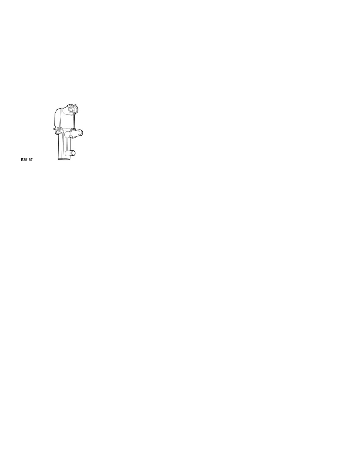
Evaporative Emissions Canister Purge Valve
The evaporative emission canister purge valve controls the flow rate of fuel vapor drawn into the engine during the canister purge operation. The valve is operated via inputs from the
engine control module (ECM).
With no ECM signal applied to the valve solenoid, the valve remains closed.
Published: 11-May-2011
Canister Purge Operation
The following pre-conditions are necessary for purging to commence:
after battery disconnection/reconnection, engine management adaptations must be re-instated.
engine has run for at least 8 seconds.
engine coolant temperature is not less than 70°C.
engine not running in the fuel cut off condition (eg overrun).
the adaptive fuel correction function has not registered a rich or lean failure.
the evaporative emission leak test has not failed.
no faults have been diagnosed in the relevant sensor and valve circuits - mass air flow (MAF) sensor, engine coolant temperature (ECT) sensor, evaporative canister purge valve
and evaporative emission canister vent solenoid.
If these conditions have been satisfied, purging is started. If any failures are registered, purging is inhibited.
The canisters are purged during each drive cycle at various rates in accordance with the prevailing engine conditions. The engine management software stores a map of engine speed
(RPM) against engine load (grams of air inducted/rev). For any given engine speed and load, a vapor purge rate is assigned (purge rate increases with engine speed and load).
The preset purge rates are based on the assumption of a vapor concentration of 100%. The actual amount of vapor is measured by the closed loop fueling system: the input of evaporative
fuel into the engine causes the outputs from the upstream oxygen sensors to change, the amount of change providing a measure of the vapor concentration. This feedback causes the
original purge rate to be adjusted and also reduces the amount of fuel input via the injectors to maintain the correct air to fuel ratio.
Engine speed/load mapping and the corresponding purge rates are different for vehicles with on-board refueling vapor recovery and vehicles without on-board refueling vapor recovery .
Vehicles With On-board Refue ling Vapor Recovery.
6/8/2011https://connect.jlrext.com/topix/service/procedure/67186/ODYSSEY/G275587/,DanaInf...
Page 2
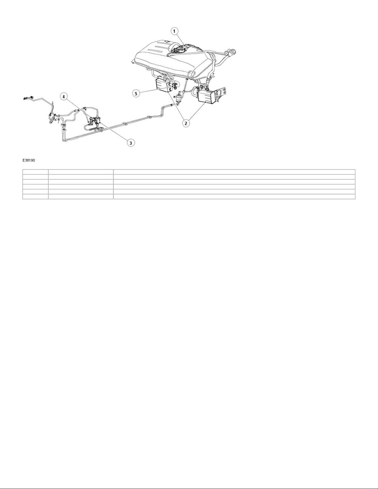
Item Part Number Description
1 — Fuel level vent valve housing
2 — Evaporative emission canisters
3 — Evaporative emission canister purge valve resonator
4 — Evaporative emission canister purge val ve
5 - Evaporative emission canister vent solenoid
The system has the following features :
Page 2 of 5
on-board refueling vapor recovery to reduce the fuel vapor vented directly to atmosphere from the filler nozzle when refueling.
a fuel tank pressure sensor and an evaporative emission canister vent solenoid are fitted to allow the on-board diagnostic facility to test for leaks in the fuel and evaporative
system.
The evaporative emission canister vent solenoid is a solenoid operated device controlled by the ECM. The valve is normally open and is closed only during the leak test sequence.
The fuel tank pressure sensor is fitted to the fuel vapor vent valve housing and provides a voltage to the ECM which is proportional to tank vapor pressure.
Operation Of On-board Refueling Vapor Re covery
The on-board refueling vapor recovery system enables fuel vapor generated during refueling to be collected by the charcoal canisters. During normal running of the vehicle, the vapor is
collected and purged in the same way as for vehicles without on-board refueling vapor recovery.
The on-board refueling vapor recovery system features are:
Narrow fuel filler pipe and tank check valve.
Fuel level vent valve fitted to the fuel vapor vent valve housing and consisting of a two stage shut-off valve with rollover protection and a pressure relief valve.
Grade vent valve with rollover protection, fitted to the fuel vapor vent valve housing and with an outlet pipe connected to the fuel level vent valve vapor outlet pipe.
Large bore vapor vent pipes.
The fuel filler pipe has a reduced diameter between the nozzle guide and the tank, providing a liquid seal when refueling and preventing the fuel vapor venting directly to atmosphere.
There is no breather tube fitted between the tank and the filler nozzle. To prevent spit back when refueling, a check valve is fitted at the lower end of the filler pipe inside the tank.
During refueling, the tank is vented via the fuel level vent valve, large bore vapor pipes and the charcoal canisters. The fuel level vent valve incorporates a float valve which is closed by
the rising fuel level, creating a back pressure and causing the fuel delivery to stop. In the closed position, the fuel level vent valve also sets the fuel level.
With the fuel level vent valve closed (tank full), any increase in pressure or overfilling is relieved by a separate rollover protected grade vent valve. The outlet from this valve feeds into the
main fuel level vent valve vapor outlet pipe, by-passing the closed fuel level vent valve.
When the fuel level is below full, the fuel level vent valve opens to allow unrestricted venting via the canisters.
A pressure relief valve is incorporated into the fuel level vent valve assembly and has an outlet pipe to the filler nozzle. If a blockage or other restriction (eg, evaporative emission canister
vent solenoid in the closed position) occurs in the vapor vent system, the pressure relief valve opens to allow venting to atmosphere via the filler nozzle guide and fuel filler cap.
Canister purge operation is as described in Evaporative Emissions.
Fuel Vapor Vent Valve Housing - Vehicles With On-Board Refueling Vapor Reco very
6/8/2011https://connect.jlrext.com/topix/service/procedure/67186/ODYSSEY/G275587/,DanaInf...
Page 3

Page 3 of 5
Item Part Number Description
1 — Grade vent valve
2 — Fuel pump module electrical connector
3 — Fuel tank pressure sensor
4 — Fuel level vent valve
5 — Fuel vapor vent valve housing locking ring
The fuel vapor vent valve housing is fitted to the top of the tank via a seal and locking ring arrangement identical to that used for vehicles without on-board refueling vapor recovery. The
fuel vapor vent valve housing is removable complete with the fitted components.
The fuel level vent valve is mounted in the fuel vapor vent valve housing via a bayonet fitting. It is turned approximately 90° clockwise to release. The grade vent valve and pressure
sensor are push in fits via sealing grommets. Note that, due to the tight fit, removal of these components may require cutting the grommets. The fuel pump/sender electrical connector is
push fitted and crimped into a location tube on the underside of the flange.
Evaporative Emission Canister, Evaporative Emission Canister Vent Solenoid and Fittings
The evaporative emission canisters are fixed to the underside of the vehicle either via semi-enclosed mounting brackets. Two fixing bolts are used at the front of the bracket and a single
rear bolt supports the evaporative emission canister and the evaporative emission canister vent solenoid.
The vapor pipes to the canisters, other than the evaporative emission canister vent solenoid, use multi-tang connectors which are push fitted and pulled out without the use of tools.
The evaporative emission canister vent solenoid has a stub pipe with 'O' ring seal which is a simple push fit into the canister. A mounting bracket on the evaporative emission canister vent
solenoid enables it to be secured to the underbody via the canister rear mounting bolt.
Standard Federal Testing Procedures (SFTP) Test Port
To comply with Standard Federal Testing Procedures (SFTP) a test port is provided in the evaporative emission canisters to purge valve resonator line to enable leak test diagnosis of the
fuel system.
Vehicles Without On-board Refueling Vapor Recovery.
6/8/2011https://connect.jlrext.com/topix/service/procedure/67186/ODYSSEY/G275587/,DanaInf...
Page 4

Page 4 of 5
Item Part Number Description
1 - Evaporative emission canister purge val ve
2 - Evaporative emission canister purge valve resonator
3 - Fuel vapor vent valve housing
4 - Evaporative emission canisters
This system uses two evaporative emission canisters. The vapor outlet from the fuel tank is taken via a rollover valve fitted to the removable flange at the top of the tank.
Canister purge operation is as described in Evaporative Emissions.
Fuel Vapor Vent Valve Housing - Vehicles Without On-board Refueling Vapor Recovery
Item Part Number Description
1 — Fuel vapor vent valve
2 — Fuel pump module electrical connector connector
6/8/2011https://connect.jlrext.com/topix/service/procedure/67186/ODYSSEY/G275587/,DanaInf...
Page 5

Page 5 of 5
3 — Fuel vapor vent valve housing locking ring
The fuel vapor vent valve housing is fitted to the top of the tank via a seal and locking ring. The assembly is removable complete with the fitted components.
The fuel vapor vent valve is a push fit via a sealing grommet. The fuel pump module electrical connector is push fitted and crimped into a location tube on the underside of the flange.
6/8/2011https://connect.jlrext.com/topix/service/procedure/67186/ODYSSEY/G275587/,DanaInf...
 Loading...