

Page 1

OWNER’S HANDBOOK
Publication Part No. JJM 10 02 30 901
Page 2

This handbook forms part of the Owner literature supplied with your new vehicle. Left-hand drive
and right-hand drive conditions may be shown in the graphics and where information is specific to
a particular country, it is indicated as such.
Please take the time to study the operating instructions with your vehicle as soon as you can.
Important
The information contained in this handbook covers all vehicle derivatives and optional equipment.
Some of the options may not be fitted to your vehicle unless they formed part of the original vehicle
specification. Therefore some parts of this handbook may not apply to your vehicle. Furthermore,
due to printing cycles, it may include descriptions of options before they become generally
available.
The options, hardware and software in your vehicle are from the available specifications for the
market in which the vehicle was intended for sale. If your vehicle is to be used in another
geographical area you may have to modify the vehicle specification to suit local conditions.
Jaguar Cars Limited is not responsible for the cost of any modifications.
The information contained in this publication was correct when it went to print. Vehicle design
changes may have been made after this handbook was printed. When this occurs a handbook
supplement is added to the literature pack. Subsequent updates can be viewed on the Jaguar
Internet site at: www.ownerinfo.jaguar.com.
In the interest of development, the right is reserved to change specifications, design or equipment
at any time without notice and without incurring any obligations. This publication, or part thereof,
may not be reproduced nor translated without our approval. Errors and omissions excepted.
© Jaguar 2008
All rights reserved.
Published by Jaguar Technical Communications.
2
Page 3

Introduction
SYMBOLS GLOSSARY ...................................... 7
LABEL LOCATIONS ........................................... 7
FACIA AND CONTROLS..................................... 8
HEALTH AND SAFETY ..................................... 10
DATA RECORDING.......................................... 10
DISABILITY MODIFICATIONS......................... 10
PARTS AND ACCESSORIES............................ 11
Keys and remote controls
PRINCIPLE OF OPERATION ............................ 13
GENERAL INFORMATION ON RADIO
FREQUENCIES ................................................ 13
USING THE REMOTE CONTROL ..................... 14
DOCKING/UNDOCKING THE JAGUAR
SMART KEY .................................................... 17
JAGUAR SMART KEY SYSTEM
TRANSMITTERS ............................................. 18
USING THE KEY .............................................. 19
CHANGING THE REMOTE CONTROL
BATTERY ........................................................ 20
PROGRAMMING THE REMOTE CONTROL...... 21
Supplementary restraints system
PRINCIPLE OF OPERATION ............................ 38
OCCUPANT SENSING ..................................... 40
DRIVER AIRBAG............................................. 42
PASSENGER AIRBAG ..................................... 43
SIDE AIRBAGS ............................................... 44
AIRBAG WARNING LAMP .............................. 44
WHIPLASH PROTECTION ............................... 44
ROLLOVER BARS ........................................... 45
AIRBAG LABELS............................................. 45
AIRBAG SERVICE INFORMATION................... 46
Child safety
CHILD SEATS ................................................. 47
CHILD SEAT POSITIONING ............................ 49
BOOSTER CUSHIONS..................................... 52
ISOFIX ANCHOR POINTS................................ 52
Pedestrian protection
PRINCIPLE OF OPERATION ............................ 56
AFTER DEPLOYMENT OF THE PEDESTRIAN
PROTECTION SYSTEM................................... 56
Locks
KEYLESS ENTRY ............................................ 23
LOCKING AND UNLOCKING............................ 23
GLOBAL OPENING AND CLOSING .................. 26
Alarm
ARMING THE ALARM ..................................... 27
DISARMING THE ALARM ............................... 28
TILT SENSOR.................................................. 28
Seats
SITTING IN THE CORRECT POSITION ............ 29
ELECTRIC SEATS............................................ 30
HEAD RESTRAINTS ........................................ 32
HEATED SEATS............................................... 33
Seat belts
GENERAL INFORMATION ............................... 34
SEAT BELT REMINDER ................................... 36
FASTENING THE SEAT BELTS ........................ 36
USING SEAT BELTS DURING PREGNANCY.... 37
Steering wheel
ADJUSTING THE STEERING WHEEL .............. 57
HORN ............................................................. 58
HEATED STEERING WHEEL............................ 58
AUDIO CONTROL ........................................... 58
CRUISE CONTROL.......................................... 59
Lighting
LIGHTING CONTROL ...................................... 60
FRONT FOG LAMPS........................................ 62
REAR FOG LAMPS.......................................... 63
HEADLAMPS - DRIVING ABROAD.................. 63
HEADLAMP LEVELLING ................................. 64
HAZARD WARNING FLASHERS...................... 64
ADAPTIVE FRONT LIGHTING
SYSTEM (AFS) ............................................... 64
DIRECTION INDICATORS ............................... 66
INTERIOR LAMPS .......................................... 67
CONVENIENCE HEADLAMPS.......................... 68
CHANGING A BULB ........................................ 68
BULB SPECIFICATION CHART ........................ 76
3
Page 4

Wipers and washers
WINDSCREEN WIPERS .................................. 77
RAIN SENSOR ................................................ 78
WINDSCREEN WASHERS............................... 78
HEADLAMP WASHERS................................... 79
CHECKING THE WIPER BLADES .................... 80
CHANGING THE WIPER BLADES.................... 80
Windows and mirrors
ELECTRIC WINDOWS ..................................... 81
EXTERIOR MIRRORS ..................................... 84
INTERIOR MIRROR ........................................ 86
Instruments
INSTRUMENT PANEL OVERVIEW .................. 89
WARNING LAMPS AND INDICATORS ............ 90
AUDIBLE WARNINGS AND INDICATORS ....... 94
Information displays
GENERAL INFORMATION ............................... 95
TOUCH-SCREEN ............................................. 96
PERSONALISED SETTINGS............................ 98
TRIP COMPUTER ......................................... 101
INFORMATION MESSAGES .......................... 103
CENTRE CUBBY BOX .................................... 124
GARAGE DOOR TRANSCEIVER..................... 125
PORTABLE AUDIO INTERFACE ..................... 128
Starting the engine
GENERAL INFORMATION.............................. 129
KEYLESS STARTING ..................................... 130
SWITCHING OFF THE ENGINE....................... 130
Transmission
AUTOMATIC TRANSMISSION....................... 131
Brakes
PRINCIPLE OF OPERATION .......................... 137
HINTS ON DRIVING WITH ABS..................... 137
ELECTRIC PARKING BRAKE (EPB) ............... 139
Parking aid
PRINCIPLE OF OPERATION .......................... 140
USING THE PARKING AID ............................. 140
Driving hints
RUNNING-IN ................................................. 143
ECONOMICAL DRIVING ................................ 144
Climate control
PRINCIPLE OF OPERATION .......................... 104
AIR VENTS ................................................... 105
AUTOMATIC CLIMATE CONTROL................. 105
HEATED WINDOWS AND MIRRORS ............ 109
Convertible top
OPENING THE CONVERTIBLE TOP............... 110
CLOSING THE CONVERTIBLE TOP ............... 115
Convenience features
MEMORY FUNCTION .................................... 119
INSTRUMENT LIGHTING DIMMER............... 120
SUN VISORS ................................................ 120
CLOCK .......................................................... 121
CIGAR LIGHTER ........................................... 122
ASHTRAY ..................................................... 122
AUXILIARY POWER SOCKETS ..................... 122
CUP HOLDERS ............................................. 123
STORAGE COMPARTMENTS ........................ 123
Cruise control
PRINCIPLE OF OPERATION .......................... 145
USING CRUISE CONTROL............................. 145
Adaptive cruise control (ACC)
PRINCIPLE OF OPERATION .......................... 147
USING ACC ................................................... 147
FORWARD ALERT FUNCTION ....................... 152
Automatic speed limiter (ASL)
PRINCIPLE OF OPERATION .......................... 154
USING THE ASL ............................................ 155
Stability control
PRINCIPLE OF OPERATION .......................... 157
4
Page 5

Fuel and refuelling
SAFETY PRECAUTIONS ................................ 159
FUEL QUALITY .............................................. 160
ALTERNATIVE FUELS ................................... 160
RUNNING OUT OF FUEL ............................... 161
FUEL FILLER FLAP........................................ 162
REFUELLING................................................. 162
FUEL TANK CAPACITY.................................. 163
FUEL CONSUMPTION ................................... 164
Load carrying
GENERAL INFORMATION ............................. 165
LUGGAGE COVERS (Coupe only).................. 165
Vehicle care
CLEANING PRODUCTS ................................. 166
CLEANING THE EXTERIOR ........................... 166
CLEANING THE INTERIOR ............................ 169
CLEANING ALLOY WHEELS .......................... 171
REPAIRING MINOR PAINT DAMAGE ............ 171
Maintenance
GENERAL INFORMATION ............................. 172
SAFETY IN THE GARAGE .............................. 174
OPENING AND CLOSING THE BONNET ........ 175
ENGINE COMPARTMENT OVERVIEW ........... 176
ENGINE OIL CHECK ...................................... 177
ENGINE COOLANT CHECK ............................ 179
BRAKE FLUID CHECK ................................... 181
POWER STEERING FLUID CHECK ................ 182
WASHER FLUID CHECK ................................ 183
TECHNICAL SPECIFICATIONS ...................... 185
Vehicle battery
BATTERY WARNING SYMBOLS ................... 186
BATTERY CARE ............................................ 186
USING BOOSTER CABLES ............................ 187
CHARGING THE VEHICLE BATTERY ............. 189
CHANGING THE VEHICLE BATTERY ............. 189
EFFECTS OF BATTERY DISCONNECTION...... 190
Wheels and tyres
GENERAL INFORMATION ............................. 191
TYRE CARE................................................... 192
TYRE PRESSURES ....................................... 193
TYRE WEAR ................................................. 195
USING WINTER TYRES ................................ 198
CHANGING A ROAD WHEEL......................... 199
TYRE REPAIR KIT......................................... 204
TYRE PRESSURE MONITORING SYSTEM.... 208
USING SNOW CHAINS ................................. 212
TYRE GLOSSARY ......................................... 212
TECHNICAL SPECIFICATIONS ...................... 213
Fuses
CHANGING A FUSE....................................... 214
FUSE BOX LOCATIONS................................. 215
FUSE SPECIFICATION CHARTS .................... 219
Emergency equipment
HAZARD WARNING FLASHERS.................... 223
WARNING TRIANGLE ................................... 223
FIRE EXTINGUISHER .................................... 223
FIRST AID KIT .............................................. 223
Status after a collision
DRIVING AFTER A COLLISION ..................... 224
ATTEMPTING TO START THE VEHICLE........ 224
MOVING THE VEHICLE ................................. 224
INSPECTING SAFETY SYSTEM COMPONENTS...
224
Vehicle recovery
TRANSPORTING THE VEHICLE .................... 226
TOWING POINTS .......................................... 227
TOWING ON FOUR WHEELS ........................ 228
Vehicle identification
VEHICLE CERTIFICATION LABEL.................. 229
VEHICLE IDENTIFICATION NUMBER (VIN)... 229
ENGINE NUMBER ......................................... 229
TRANSMISSION NUMBER ........................... 229
VEHICLE BUILT DATE................................... 229
5
Page 6

Technical specifications
ENGINE SPECIFICATIONS ............................ 230
WEIGHTS...................................................... 230
DIMENSIONS................................................ 231
WHEEL ALIGNMENT DATA (CHINA ONLY) .. 232
Audio introduction
RADIO RECEPTION....................................... 233
Audio unit overview
AUDIO UNIT OVERVIEW............................... 234
Audio unit operation
ON/OFF CONTROL ........................................ 238
AUDIO CONTROL ......................................... 238
JAGUAR PREMIUM SURROUND SOUND..... 241
WAVEBAND BUTTON ................................... 243
AUTOSTORE CONTROL ................................ 243
STATION PRESET BUTTONS ........................ 244
TRAFFIC INFORMATION CONTROL .............. 244
Audio unit menus
RADIO DATA SYSTEM (RDS) ....................... 246
REGIONAL MODE (REG) .............................. 248
ENHANCED OTHER NETWORK
(RDS-EON) ................................................... 248
ALTERNATIVE FREQUENCIES ...................... 249
Telephone
GENERAL INFORMATION.............................. 263
TELEPHONE CONTROLS............................... 265
TELEPHONE PAIRING AND DOCKING........... 266
SETTINGS MENUS ........................................ 270
USING THE TELEPHONE ............................... 272
PHONEBOOK ................................................. 275
Appendices
TYPE APPROVALS ........................................ 277
Compact disc player
LOADING COMPACT DISCS ......................... 250
EJECTING COMPACT DISCS ........................ 251
COMPACT DISC SELECTION ........................ 252
TRACK SELECTION....................................... 252
COMPACT DISC PAUSE................................ 253
REPEAT COMPACT DISC TRACKS ............... 253
SHUFFLE/RANDOM ...................................... 253
COMPACT DISC DISPLAY OPTIONS ............ 254
MP3 FILE PLAYBACK ................................... 254
Portable audio
PORTABLE AUDIO ........................................ 256
PORTABLE AUDIO DEVICES......................... 258
6
Page 7

Introduction
1
2
6
1
2
3
5
4
E90641
SYMBOLS GLOSSARY
Warnings
WARNING
Safety warnings are included in this
handbook. These indicate either a
procedure which must be followed
precisely, or information that should be
considered with great care in order to avoid
the possibility of personal injury.
Warning labels
Labels are attached to your vehicle at several
positions. These are applied to draw your
attention to important subjects, e.g. tyre
pressures, airbags, engine compartment
hazards, etc.
Cautions
CAUTION
Cautions are included in this handbook.
These indicate either a procedure which
must be followed precisely, or information that
should be considered with great care in order
to avoid the possibility of damage to your
vehicle.
Symbols
This recycling symbol identifies
those items that must be disposed
of safely in order to prevent
unnecessary damage to the environment.
This symbol identifies those
features that can be adjusted,
disabled or enabled by a Jaguar
Dealer/Authorised Repairer.
LABEL LOCATIONS
instructions in the handbook.
while the starter switch is turned on.
Warning labels attached to your
vehicle bearing this symbol mean:
Do not touch or adjust components
until you have read the relevant
Labels showing this symbol
indicate that the ignition system
utilises very high voltages. Do not
touch any ignition components
1. Vehicle certification, Airbag, Child
restraint, Tyre placard, E. Approval.
2. Air conditioning.
3. Under bonnet warnings.
4. Coolant warnings.
5. Fuel warnings.
6. Battery.
It is important that you are familiar with these
subjects to ensure that your vehicle and its
features are used safely. Using the index at the
back of this handbook, refer to the relevant
topic for more information.
7
Page 8
Introduction
Au
k
Ist u
10k
2017
19
18
16
21
Au
l
Ist u
E92027
23
25
27
28
26
1 2 3 4 5 6 7 8 9 10 11 12 13 14
1720
19
18
22
24
16
15
29
21
1 2 3 4 5 6 7 8 9 10
22
23
25
27
28
26
24
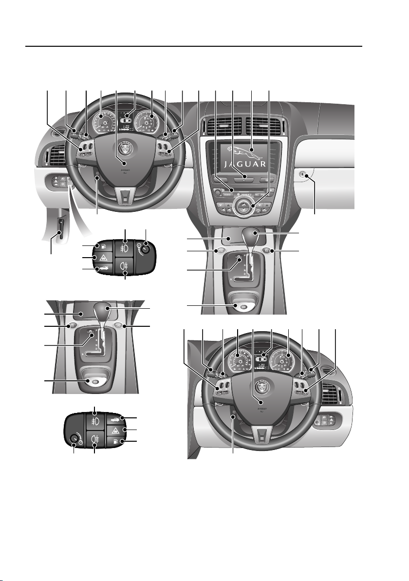
FACIA AND CONTROLS
8
Page 9

Introduction
1. Steering wheel audio switches. See AUDIO
CONTROL (page 58).
2. External lamp switches. See LIGHTING
CONTROL (page 60).
3. Jaguar sequential gear change down
paddle. See AUTOMATIC TRANSMISSION
(page 131).
4. Speedometer. See INSTRUMENT PANEL
OVERVIEW (page 89).
5. Driver’s horn and airbag. See HORN
(page 58).
6. Message centre. See GENERAL
INFORMATION (page 95).
7. Tachometer. See INSTRUMENT PANEL
OVERVIEW (page 89).
8. Jaguar sequential gear change up paddle.
See AUTOMATIC TRANSMISSION
(page 131).
9. Wiper and washer switch. See
WINDSCREEN WIPERS (page 77).
10. Cruise control or Adaptive Cruise Control
switches. See USING CRUISE CONTROL
(page 145). See USING ACC (page 147).
11. Audio panel. See AUDIO UNIT OVERVIEW
(page 234).
12. Hazard warning switch. See HAZARD
WARNING FLASHERS (page 64).
13. Touch-screen display. See
TOUCH-SCREEN (page 96).
14. Climate control panel. See AUTOMATIC
CLIMATE CONTROL (page 105).
15. Glove box compartment release button.
See STORAGE COMPARTMENTS
(page 123).
16. Gear selector. See AUTOMATIC
TRANSMISSION (page 131).
17. Automatic speed limiter switch. See
USING THE ASL (page 155).
18. Electric parking brake switch. See
ELECTRIC PARKING BRAKE (EPB)
(page 139).
19. Dynamic stability control mode switch.
See Stability control (page 157).
20. Engine Start and Stop switch. See
K
EYLESS STARTING (page 130).
21. Ashtray and cigar lighter. See CIGAR
LIGHTER (page 122).
22. Steering column adjustment switch. See
ADJUSTING THE STEERING WHEEL
(page 57).
23. Front fog lamps. See FRONT FOG LAMPS
(page 62).
24. Dimmer switch. See INSTRUMENT
LIGHTING DIMMER (page 120).
25. Rear fog lamp switch. See REAR FOG
LAMPS (page 63).
26. Luggage compartment release switch. See
LOCKING AND UNLOCKING (page 23).
27. Forward alert switch. See FORWARD
ALERT FUNCTION (page 152).
28. Fuel filler flap release switch. See FUEL
FILLER FLAP (page 162).
29. Bonnet release lever. See OPENING AND
CLOSING THE BONNET (page 175).
Page numbers (shown in brackets) refer to
pages in this handbook that have further
relevant information.
9
Page 10

Introduction
HEALTH AND SAFETY
WARNINGS
The vehicle should not be parked over
long dry grass or other combustible
material, particularly during dry
weather. As the heat generated by the exhaust
and emission control systems may be
sufficient to start a fire.
Before exiting the vehicle, ensure the
P park is selected and the parking
brake is applied. When exiting the
vehicle make sure that the Jaguar Smart Key is
removed from the vehicle.
DATA RECORDING
Service data recording
Service data recorders in your vehicle are
capable of collecting and storing diagnostic
information about your vehicle. This potentially
includes information about the performance or
status of various systems and modules in the
vehicle such as engine, throttle, steering or
brakes.
In order to properly diagnose and service your
vehicle, Jaguar Cars Limited and service and
repair facilities may access vehicle diagnostic
information through a direct connection to
your vehicle.
Event data recording
Event data recorders are capable of collecting
and storing data during a crash or near-crash
event. The recorded information may assist in
the investigation of such an event. The
modules may record information about both
the vehicle and the occupants, potentially
including information such as:
• How various systems in your vehicle were
operating.
• Whether or not the driver and passenger
seat belts were buckled.
• How far, if at all, the driver was depressing
the accelerator and/or the brake pedal.
• How fast the vehicle was travelling.
• Where the driver was positioning the
steering wheel.
To access this information special equipment
must be connected directly to the recording
modules. Jaguar Cars Limited do not access
event data recorder information without
obtaining consent, unless pursuant to court
order or where required by law enforcement,
other government authorities or third parties
acting with lawful authority.
Other parties may seek to access the
information independently of Jaguar Cars
Limited.
DISABILITY MODIFICATIONS
Occupants with disabilities which may require
modifications of the vehicle must contact a
Jaguar Dealer/Authorised Repairer before any
modifications are made.
10
Page 11

Introduction
PARTS AND ACCESSORIES
WARNINGS
The fitting of non-approved parts and
accessories, or the carrying out of
non-approved alterations or
conversions, may be dangerous and could
affect the safety of the vehicle and occupants
and also invalidate the terms and conditions of
the vehicle warranty.
Jaguar will not accept any liability for
death, personal injury or damage to
property which may occur as a direct
result of fitment of non-approved accessories
or the carrying out of non-approved
conversions to Jaguar vehicles.
Jaguar strongly advise against
making any modifications to the
suspension or steering system. This
could seriously affect the handling and
stability of the vehicle leading to loss of control
or rollover.
The vehicle has been designed, built and tested
to cope with a variety of driving conditions,
some of which can place the severest possible
demands on control systems and components.
As such, fitting replacement parts and
accessories that have been developed and
tested to the same stringent standards as the
original components will safeguard the
continued reliability, safety and performance of
your vehicle.
To augment the vehicle's already impressive
performance, a comprehensive range of Jaguar
approved spare parts and accessories is
available.
Jaguar parts are the only parts built to original
equipment specifications and approved by
Jaguar designers; this means that every single
part and accessory has been rigorously tested
by the same engineering team that designed
and built the vehicle.
A full list and description of all accessories is
available from your Jaguar Dealer/Authorised
Repairer.
Electrical equipment
WARNING
It is extremely hazardous to fit or
replace parts or accessories, the
installation of which requires the
dismantling of, or addition to, either the
electrical or fuel systems.
Always consult a Jaguar Dealer/Authorised
Repairer before fitting any accessory.
Fitting inferior quality parts or accessories,
may be dangerous and could invalidate the
vehicle warranty.
It is recommended that you always consult a
Jaguar Dealer/Authorised Repairer for advice
regarding the approval, suitability, installation
and use of any parts or accessories before
fitting.
11
Page 12
Introduction
E90644
Airbag system
WARNING
The components that make up the
airbag system are sensitive to
electrical or physical interference,
either of which could easily damage the
system and cause inadvertent operation or a
malfunction of the airbag module.
To prevent malfunction of the airbag system
always consult a Jaguar Dealer/Authorised
Repairer before fitting any of the following:
• Electronic equipment such as a mobile
phone, two-way radio or in-car
entertainment system.
• Accessories attached to the front of the
vehicle.
• Any modification to the front of the vehicle.
• Any modification involving the removal or
repair of any wiring or component in the
vicinity of any of the airbag system
components, including the steering
column, instrument or facia panels.
• Any modification to the facia panels or
steering wheel.
Travelling abroad
In certain countries, it is a legal requirement to
fit parts made to the vehicle manufacturers'
specification.
Owners should ensure that any parts or
accessories fitted to the vehicle while travelling
abroad will also conform to the legal
requirements of their own country when they
return home.
After-sales service
The After Sales Parts service is of paramount
importance, with franchised representation in
over 100 countries worldwide, Jaguar are able
to support your vehicle wherever you go.
12
Page 13
Keys and remote controls
E90670
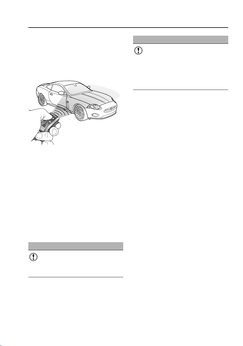
PRINCIPLE OF OPERATION
The security system and entry to the vehicle are
controlled by the Jaguar Smart Key. Both doors
and the luggage compartment can be locked
and unlocked using the remote control
buttons.
Keyless entry is an enhancement of the Jaguar
Smart Key. It allows entry to the vehicle
without any button pressing.
Full security integrity of the vehicle is still
maintained.
The remote control also allows the vehicle to be
started without the use of an ignition key. See
KEYLESS STARTING (page 130).
Two handsets, comprising of a transmitter
body with a detachable metal emergency key
blade are supplied. Separate emergency key
blades are available from Jaguar Dealers/
Authorised Repairers.
CAUTIONS
If a remote control is lost, a replacement
can be obtained and programmed to the
vehicle by a Jaguar Dealer/Authorised
Repairer. Notify a Jaguar Dealer/Authorised
Repairer as soon as a remote control is lost or
stolen and have the remaining remote
control(s) reprogrammed.
The emergency key blade number is recorded
on an attached label. Peel off the label and
attach it to the designated area on the Security
Card supplied in the vehicle literature pack.
Keep the Security Card safe, but not in the
vehicle.
GENERAL INFORMATION ON RADIO
FREQUENCIES
Note: The radio frequency used by your Jaguar
Smart Key may be used by other devices. For
example: amateur radios, medical equipment,
wireless headphones, or other remote control
devices. This may cause the frequency to be
jammed, and prevent your Jaguar Smart Key
from operating correctly.
Environmental conditions can affect the
operation of your Jaguar Smart Key and the
operating range may vary considerably
depending on the vehicle's location.
CAUTIONS
Remove all remote controls from the
vehicle when it is left unattended. This
will ensure the vehicle is left in a secure
condition.
13
Page 14
Keys and remote controls
4 3 2
1
7
6
5
E90683
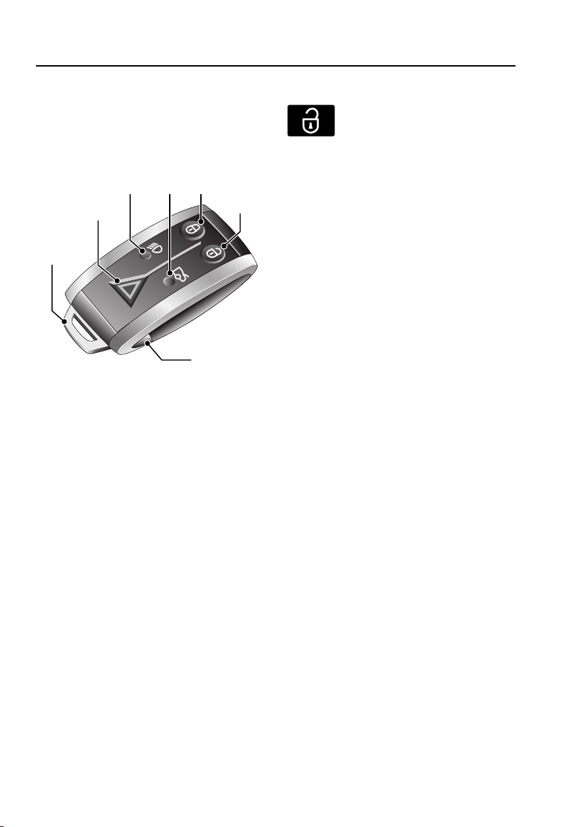
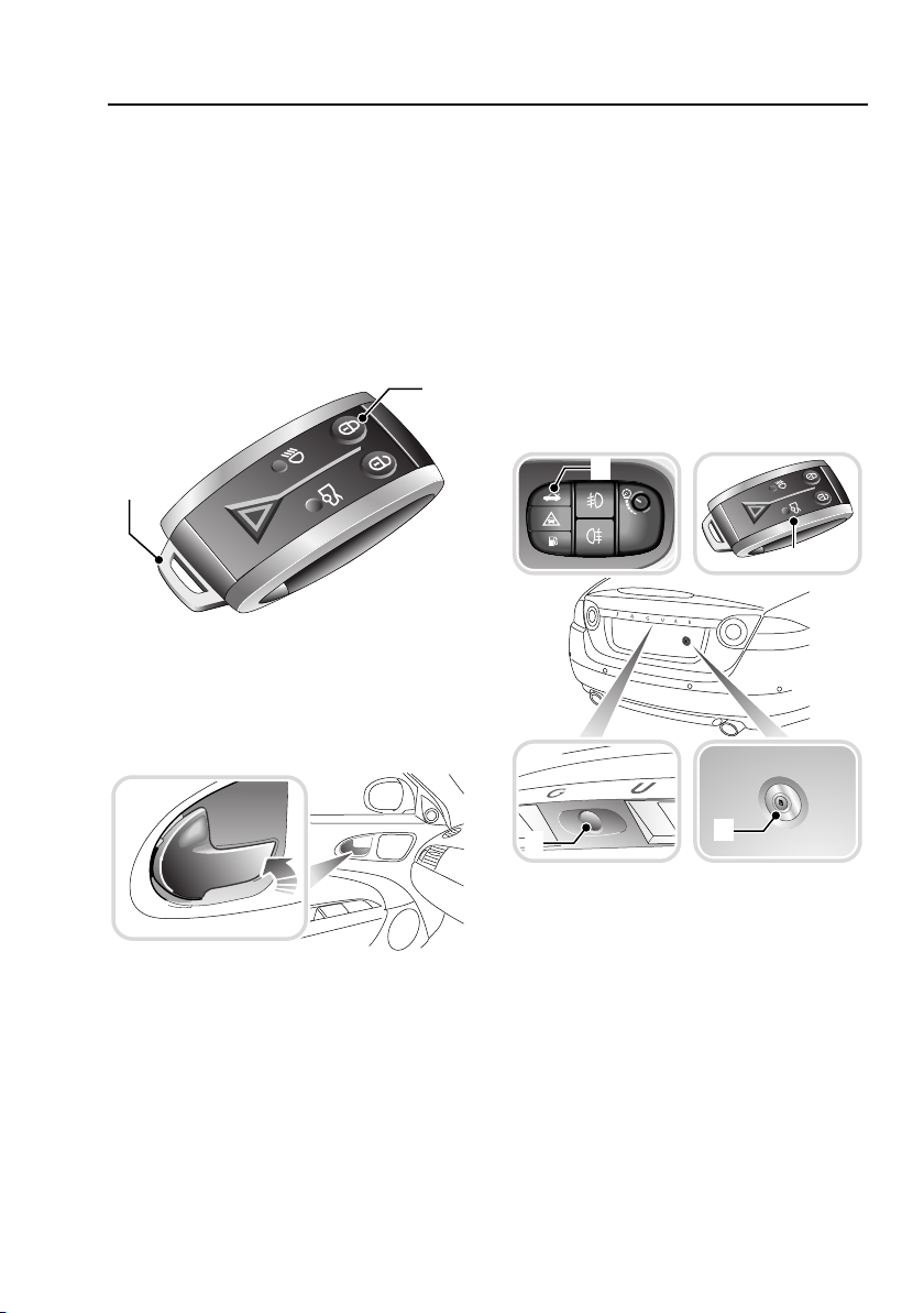
USING THE REMOTE CONTROL
Some features of the remote control can be
programmed via the touch-screen settings.
See PROGRAMMING THE REMOTE CONTROL
(page 21).
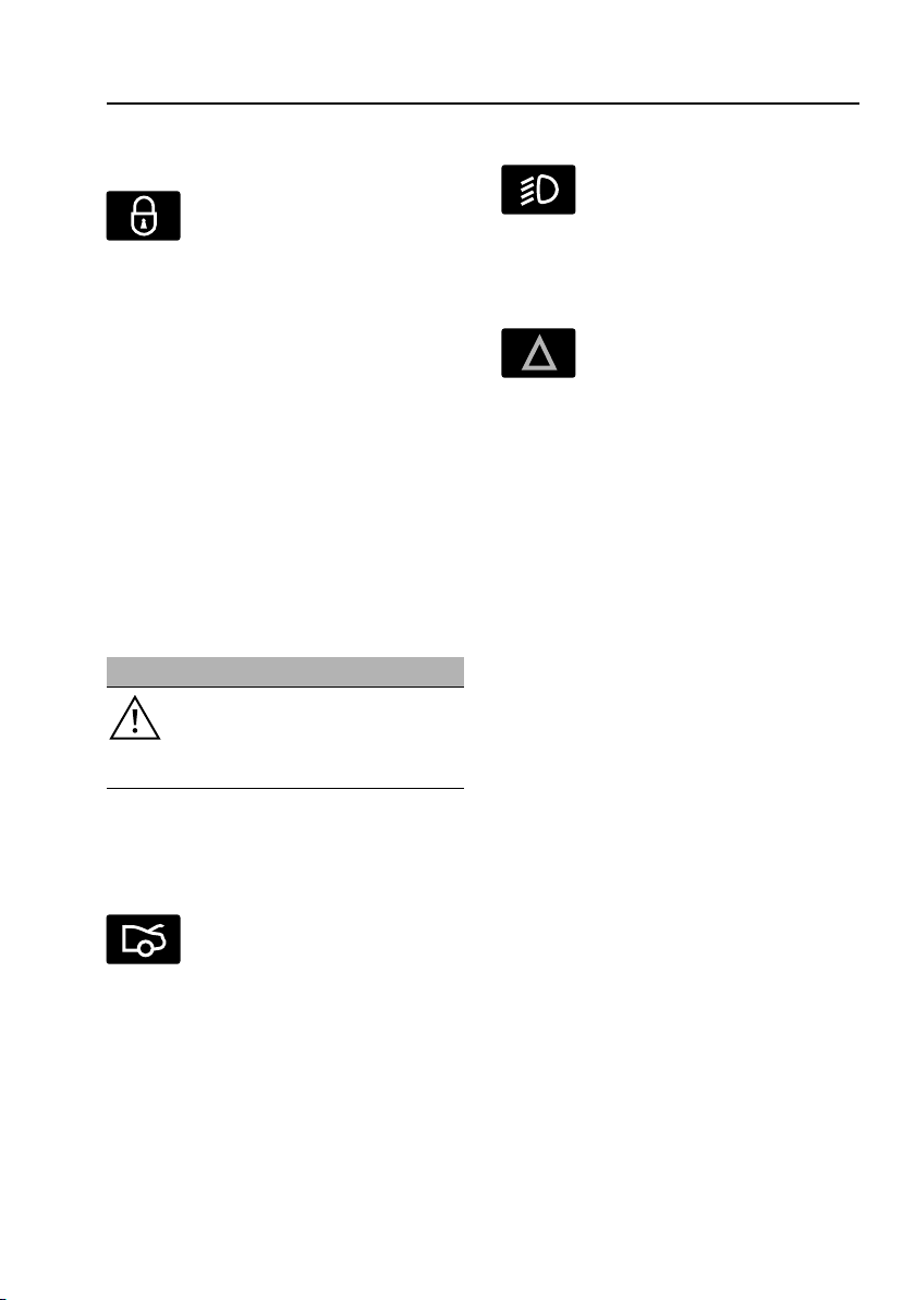
1. Unlock.
2. Lock.
3. Luggage compartment release.
4. Convenience headlamp feature.
5. Panic button.
6. Emergency key blade.
7. Emergency key blade release button.
Unlocking and disarming the vehicle
One press: Unlocks all doors and
the luggage compartment. The
direction indicators will flash twice.
Two stage unlocking
One press: Unlocks the driver’s door and the
luggage compartment. The direction indicators
will flash twice (in certain markets two audible
warnings will be emitted).
Two presses (within three seconds): Unlocks
the passenger door.
The door mirrors will unfold if this option is
selected using the touch-screen. See
EXTERIOR MIRRORS (page 84).
Note: The door mirrors will not unfold if they
have been folded via the door mirror switches.
Note: Changing from central locking to two
stage locking and back again can be carried out
by pressing the lock and unlock buttons
simultaneously for four seconds or via the
touch-screen. See PROGRAMMING THE
REMOTE CONTROL (page 21). The direction
indicators will flash twice to confirm that the
change has been carried out.
Press and hold the button to activate global
opening, if enabled. See PROGRAMMING THE
REMOTE CONTROL (page 21). This opens all
windows as well as the programmed door
opening.
14
Page 15
Keys and remote controls
Locking, double-locking and arming the
alarm
One press: Locks all doors,
luggage compartment and sets the
alarm system. The direction
indicators will flash once (in certain markets an
audible warning will be emitted).
Two presses (within three seconds of first
press): Double-locks all doors and sets the
alarm system to provide the highest level of
security - use whenever possible.
The direction indicators will flash once for lock
and an additional long flash for double-lock. In
certain markets, two warning tones will
indicate that the doors are doubled-locked.
Note: The interior door handles are
immobilised.
Press and hold: Globally closes the vehicle’s
windows, if enabled. See PROGRAMMING THE
REMOTE CONTROL (page 21).
WARNING
Double-locking should never be used
when persons or animals are to
remain inside the vehicle. In an
emergency they would not be able to escape.
The door mirrors will fold back if the powerfold
option is selected using the touch-screen
setting. See EXTERIOR MIRRORS (page 84).
Activating the convenience headlamps
Press to switch on the headlamps.
The headlamps will remain on for
25 seconds, or until the button is
pressed again, or until the engine START/STOP
button is pressed.
Activating the panic alarm
Press and hold the panic button for
three seconds or press the button
three times within three seconds.
The horn and hazard warning lamps will
operate.
The alarm is stopped by:
• Pressing the button again three times
within three seconds.
• Inserting the Jaguar Smart Key into the
starter control unit.
• The vehicle detecting a valid Jaguar Smart
Key when the START/STOP button is
pressed.
Note: The panic alarm cannot be cancelled
within the first five seconds of the alarm
activating.
Unlocking the luggage compartment
Press to open the luggage
compartment lid. When the vehicle
alarm system is armed and the
luggage compartment only is opened, the door
and bonnet security is still active. The doors
will remain locked and armed. See LOCKING
AND UNLOCKING (page 23).
15
Page 16
Keys and remote controls
E90689
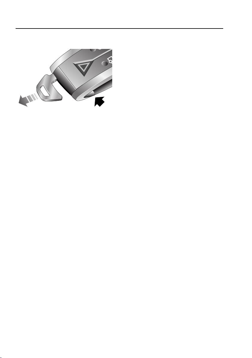
Releasing the emergency key blade
To extract: press the release button and hold
while withdrawing the key blade.
To insert: press and hold the button and push
the key blade into the Jaguar Smart Key
transmitter housing.
The key blade operates the door lock on the
left-hand side of the vehicle, the luggage
compartment lock and glove compartment
lock. See USING THE KEY (page 19).
Care of the remote handset
Do not expose to extremes of heat, dust,
humidity or allow contact with fluids. Do not
leave the transmitter exposed to direct
sunlight.
Until the battery can be replaced, or until the
vehicle is outside the local electrical
interference zone, the Jaguar Smart Key can be
inserted into the starter control unit. See
DOCKING/UNDOCKING THE JAGUAR SMART
KEY (page 17).
Coded keys
This vehicle is equipped with a Passive
Anti-Theft System (PATS) which prevents it
from being driven away by an unauthorised
person.
A sophisticated decoding process is used to
validate the Jaguar Smart Key. The engine can
only be started by the key that is programmed
to the vehicle electronic systems.
Irregular remote control operation
If difficulty is experienced with remote keyless
entry, passive entry, passive starting or Jaguar
Smart Key operation, it may be caused by:
• Internal battery low voltage and therefore
the battery should be replaced. See
CHANGING THE REMOTE CONTROL
BATTERY (page 20). or
• High levels of localised external electrical
interference e.g. radio transmitter.
16
Page 17

Keys and remote controls
1
2
3
E90690
E90691
1
3
2
DOCKING/UNDOCKING THE JAGUAR
SMART KEY
Docking the Jaguar Smart Key
1. Lift the lid of the centre console stowage
compartment.
2. Slide open the cover of the starter control
unit.
3. Insert the Jaguar Smart Key into the recess
with the emergency key release button
facing forward.
Note: This is not a Jaguar Smart Key internal
battery recharging procedure. The battery is
non-rechargeable.
Undocking the Jaguar Smart Key
To remove the Jaguar Smart Key from the
starter control unit:
1. Ensure that the vehicle is at rest with the
gear selector in the P position and the
engine not running.
2. Carefully depress the Jaguar Smart Key
and release. The key will eject into its rest
position.
3. Remove the Jaguar Smart Key from the
starter control unit.
17
Page 18
Keys and remote controls
5
6
5
6
1
2
2
1
4
4
4
3
3
E90692
Message centre information displays
Message Warning
indicator
SMART KEY NOT
FOUND, PLEASE
INSERT IN SLOT
CHECK SMART KEY None None Check that the Jaguar Smart Key is
WRONG SMART KEY
FOUND
REMOVE SMART KEY None None Remove the Jaguar Smart Key from
None None The Jaguar Smart Key has not been
None None The Jaguar Smart Key detected by
Priority
indicator
Meaning
detected, insert into the starter
control unit.
in the vehicle.
the in-vehicle systems is not the
one belonging to the vehicle.
the starter control unit.
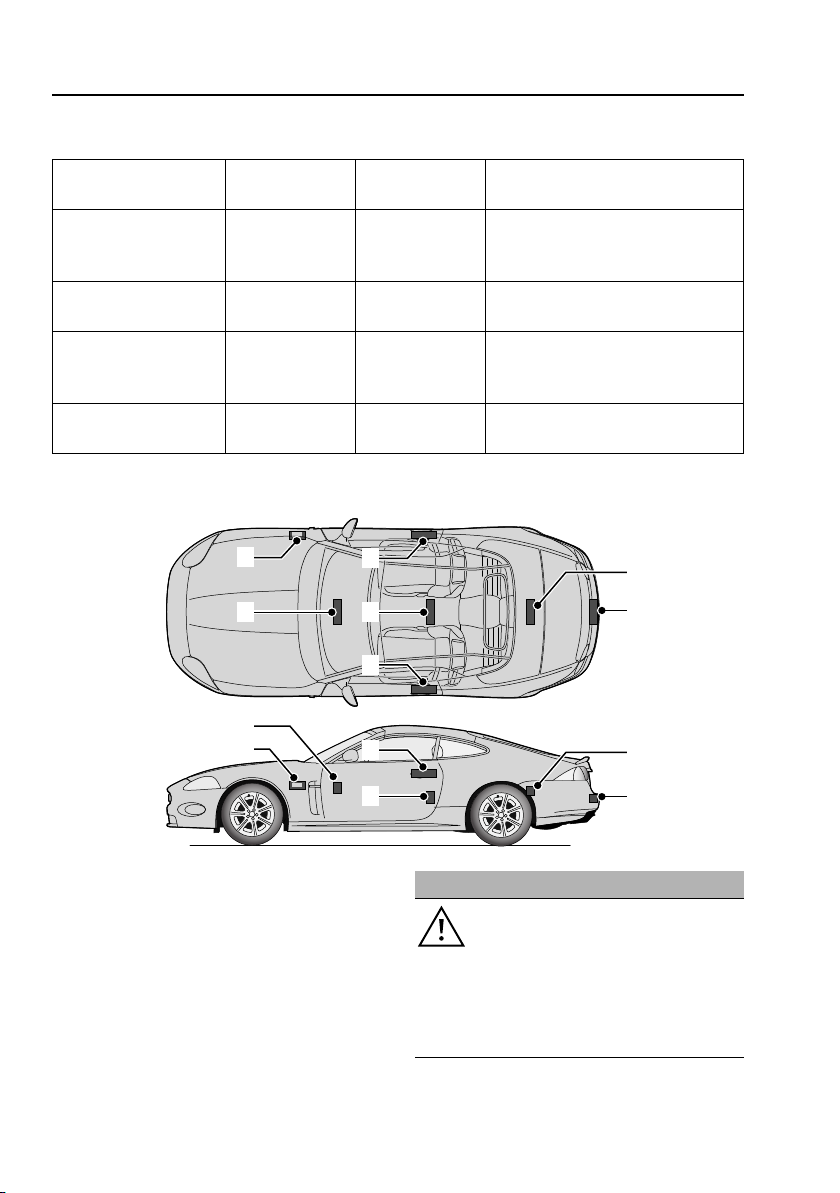
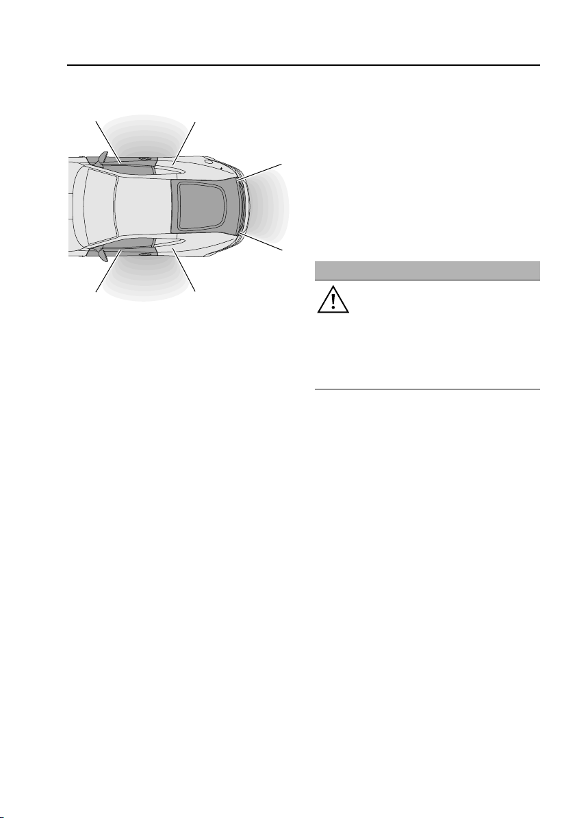
JAGUAR SMART KEY SYSTEM TRANSMITTERS
1. Cabin front transmitter.
2. Keyless vehicle module.
3. Cabin rear transmitter.
4. Exterior door handle transmitters.
5. Luggage compartment interior
transmitter.
6. Luggage compartment exterior
transmitter.
Any person fitted with an implanted
medical device should ensure that the
device is kept at a distance of at least
22 cm (8.7 inches) away from any transmitter
mounted in the vehicle. This is to avoid any
possibility of interference between the system
and device.
18
WARNING
Page 19

Keys and remote controls
E93156
USING THE KEY
Emergency key blade use
Remove the left-hand door lock cover by
inserting a suitable tool into the slot on the
underside of the cover. Push upwards and
twist to release the cover retaining clips. Insert
the key blade into the exposed lock.
To refit the door lock cover, reposition the top
of the cover, locating it over the upper tab.
Keeping the top of the cover in position, push
firmly on the right-hand end and then the
bottom of the cover, so that it clicks into place.
Note: Ensure that the emergency key blade is
kept safely at all times.
To lock the vehicle
Ensure all the doors are closed, then turn the
key blade towards the front of the vehicle and
release.
This will lock the doors and the luggage
compartment, but will not arm the alarm.
To unlock the vehicle
Turn the key blade towards the rear of the
vehicle and release. If the security system is
disarmed, all doors and the luggage
compartment will be unlocked. If the security
system is armed, only the front left-hand door
will unlock. The interior lighting will be turned
on at a reduced level for two minutes.
If the vehicle is unlocked using the emergency
key blade with the security system armed, the
alram will sound when a door is opened. To
deactivate the alarm, press the unlock button
on the Jaguar Smart Key or dock the Jaguar
Smart Key into the starter control unit. See
USING THE REMOTE CONTROL (page 14).
Alternatively, press the engine START/STOP
button. The direction indicators give two
flashes (in certain markets two audible
warnings will be given).
Valet mode
Valet mode allows the vehicle to be parked by a
parking attendant who can lock the vehicle
after parking, but cannot open the luggage or
glove compartments.
The key blade is used to lock the glove
compartment. Use the touch-screen to set the
valet mode and secure the luggage
compartment. See PROGRAMMING THE
REMOTE CONTROL (page 21).
19
Page 20
Keys and remote controls
2
3
5
2
4
1
E90710
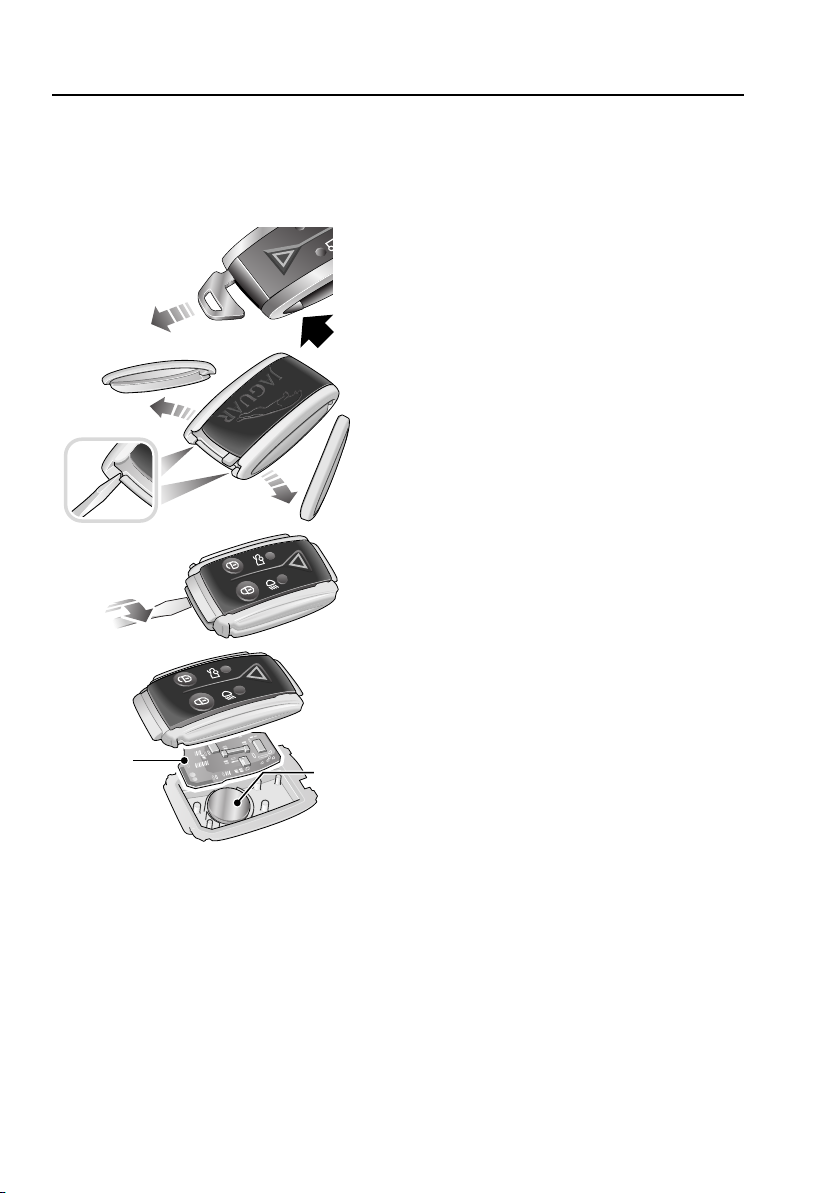
CHANGING THE REMOTE CONTROL
BATTERY
Battery renewal
To renew the battery, follow the procedure
below:
1. Remove the key blade from the Jaguar
Smart Key. See USING THE REMOTE
CONTROL (page 14).
2. Remove the two side covers, one at a time,
by inserting a small, flat-bladed,
screwdriver between the cover and body
and twist the screwdriver.
3. Insert a small, flat-bladed, screwdriver
between the two body halves of the remote
handset. Apply light pressure to the
screwdriver and separate the two halves.
4. Remove the printed circuit board, taking
care not to touch the battery terminals.
Remove the old battery and dispose of it
safely.
5. Fit a new battery cell, type CR2032
(available from your Jaguar Dealer/
Authorised Repairer), with the side marked
with the positive symbol (+) downwards in
the battery receptacle. Avoid touching the
new battery as moisture and oil from the
fingers can reduce the life of the battery
and corrode the contacts.
Refit the parts in the reverse order making sure
that they click securely into place.
When the battery needs renewing there will be
a significant decrease in the effective range of
the key transmitter and the message SMART
KEY BATTERY LOW is displayed on the
message centre.
20
Page 21
Keys and remote controls
Vehicle
Security
Parking
Valet mode
2 stage unlock Off On
Intrusion/tilt Off On
Vehicle
Security
Parking
Valet mode
Off On
Global close Off On
Off On
Global open
Drive away
locking
12 : 26 pm
12 : 26 pm
Off On
Mirror fold back
E90740
Vehicle
Security
Parking
Valet mode
2 stage unlock Off On
Intrusion/tilt Off On
12 : 26 pm
Off On
Mirror fold back
E90741
Vehicle
Security
Parking
Valet mode
2 stage unlock Off On
Intrusion/tilt Off On
12 : 26 pm
Off On
Mirror fold back
E90742
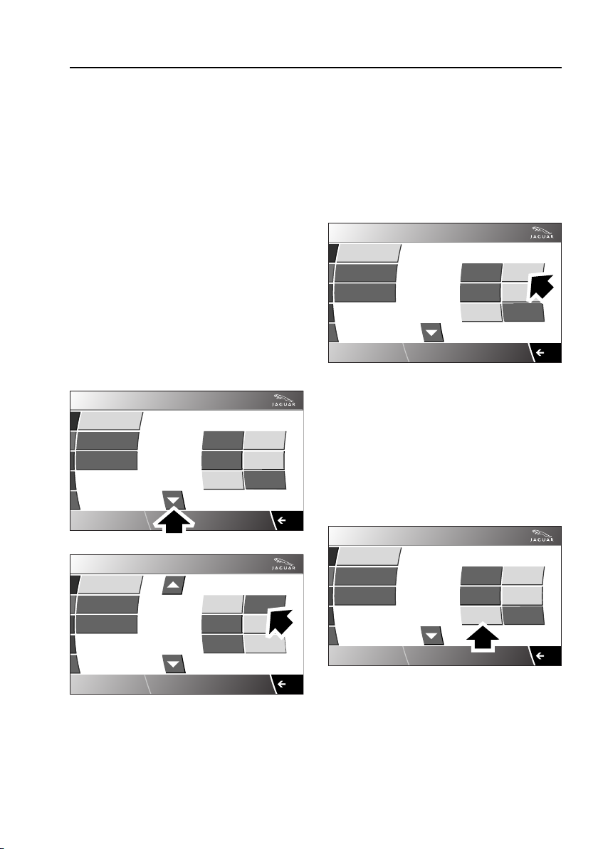
PROGRAMMING THE REMOTE
CONTROL
The remote handset, Jaguar Smart Key, and
various features of the vehicle security system
can be programmed to your individual
requirements by use of the touch-screen.
The programmable features are as follows:
• Drive-away locking.
• Central or two stage locking.
• Sensor override.
• Window global open or close, passive
entry vehicles only.
• Valet key mode.
Selecting drive-away locking
From the touch-screen Home menu, select
Vehicle:
2. The Security menu is displayed
automatically as the default.
3. Scroll down to Drive away locking and
select either On or Off.
Selecting central or two stage locking
From the touch-screen Home menu, select
Vehicle:
1. Select Veh. settings.
2. The Security menu is displayed
automatically as the default.
3. Select 2 stage unlock On or Off.
Selecting intrusion-tilt sensor
From the touch-screen Home menu, select
Vehicle:
1. Select Veh. settings.
1. Select Veh. settings.
2. The Security menu is displayed
automatically as the default.
3. Select Intrusion/tilt On or Off.
21
Page 22

Keys and remote controls
Valet off - enter pin
Vehicle
Security
Parking
Valet mode
12 3
4 6
78 9
0
C
OK
12 : 26 pm
E90743
Valet on - enter pin
Vehicle
Security
Parking
Valet mode
12 3
4 6
78 9
0
C
OK
12 : 26 pm
E90744
This will override the interior and tilt sensors
until the engine is next started. It is normally
used for recovery of the vehicle or when
travelling on a ferry.
Selecting global opening or closing
From the touch-screen Home menu, select
Vehicle:
1. Select Veh. settings.
2. The Security menu is displayed
automatically as the default.
3. Scroll down to Global open or Global
close and select either On or Off.
Valet mode
From the touch-screen Home menu, select
Vehicle:
1. Select Veh. settings.
2. The Security menu is displayed
automatically as the default.
3. Select Valet mode.
4. Enter a four digit Personal Identification
Number (PIN) (personally chosen) by
touching the digit screen pad. On
completion touch the OK button. The
screen indicates that the PIN has been
accepted by displaying Valet on. If you
wish to cancel the PIN, touch the C button
at any time during entering the number.
• The luggage compartment is now securely
locked in the valet mode.
• On exiting and securing the vehicle, hand
the Jaguar Smart Key, less the key blade,
to the attendant.
Note: Ensure that the emergency key blade is
kept safely at all times.
De-selecting valet mode: When entry into the
vehicle has been gained, access the Valet mode
screen.
1. Enter your four digit PIN and touch the OK
button. The screen will indicate that your
PIN has been accepted by displaying Valet
off.
2. The luggage compartment will return to
the previously set security requirement.
3. Unlock the glove box using the key blade.
4. Insert the key blade into the Jaguar Smart
Key.
Note: If the PIN number has been forgotten,
the luggage compartment can be unlocked by
using the key blade in the luggage
compartment lock. This will cancel the valet
mode. See LOCKING AND UNLOCKING
(page 23).
• Using the key blade, lock the glove box.
22
Page 23
Locks
E90715
KEYLESS ENTRY
The Keyless entry function operates in the
following manner:
1. As a door handle is operated, the vehicle
emits a search signal.
2. As long as the Jaguar Smart Key is within
approximately 1.0 metre (3 feet 3 inches)
of the operated door handle, the signal will
be acknowledged.
• The Jaguar Smart Key requires only to
be on the driver's person or in a bag or
non-metallic briefcase; it does not
require to be exposed or handled.
3. The vehicle accepts the valid response and
allows access via either door. The direction
indicators will flash twice (in certain
markets two audible warnings will be
emitted).
• You are unlikely to notice a time lag
during this momentary process.
Two stage unlocking: Access to the vehicle is
via the first door handle operated. The other
door can be opened by releasing the internal
door lock or via operating the exterior door
handle with the Jaguar Smart Key present.
Jaguar Smart Key check
When the last open door is closed, the vehicle
will perform a search of the vehicle interior for
the Jaguar Smart Key. If one is not found a
message SMART KEY NOT FOUND, PLEASE
INSERT IN SLOT will be displayed for four
seconds on message centre. This is to alert the
driver that the Jaguar Smart Key may have
been inadvertently removed from the vehicle.
LOCKING AND UNLOCKING
WARNING
The door windows partially lower and
raise automatically when the door is
opened and closed. Keep fingers
away from the windows when closing the
door. Closing an electrically operated window
on fingers, hands or any vulnerable part of the
body, can result in serious injury.
Note: It will not be possible to lock the vehicle
if any door, bonnet or luggage compartment is
ajar or if the inertia switch has been tripped.
See DRIVING AFTER A COLLISION (page 224).
An audible warning will be emitted.
Convenience mode
As the door is opened, the vehicle’s electrical
system initiates convenience mode. The
following systems become functional:
• Memory.
• Seat and steering column adjustment.
• Interior and exterior lighting.
• Message centre.
• Cigar lighter and power socket.
23
Page 24
Locks
E90717
Steering column lock
An electronic steering column lock is fitted to
the steering column.
It is unlocked when a recognised remote
handset, Jaguar Smart Key, is inside the
vehicle.
The steering column is automatically locked
when the engine and ignition systems are off,
the gear selector is in P (Park) and the driver’s
door is opened.
CAUTION
During vehicle recovery the remote
handset must remain inside the vehicle
or be stowed in the starter control unit in the
centre console so that the steering remains
unlocked.
Any malfunction of the steering column lock
will be indicated by the message STEERING
COLUMN LOCKED displayed by the message
centre. If this occurs:
1. Press the engine START/STOP button to
return to convenience mode.
2. Try again to unlock the steering column by
turning the steering wheel gently to the left
and right.
3. If the malfunction still persists, seek
qualified assistance as soon as possible.
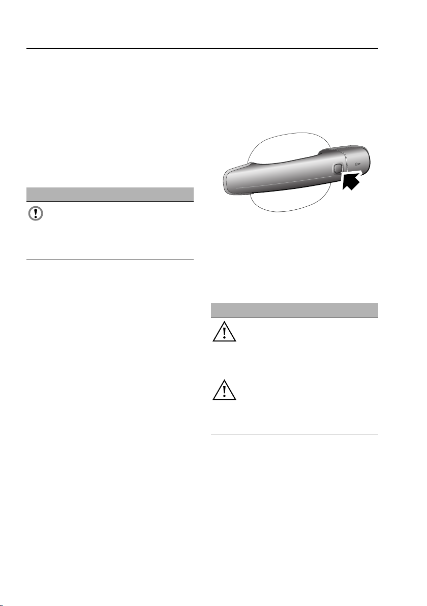
External door lock operation - with
keyless entry
Note: The keyless locking system will only
activate if the remote handset is outside the
vehicle.
To lock the vehicle and set the alarm
1. Press the door handle button once, or;
2. Use the Jaguar Smart Key.
Note: The vehicle will not lock automatically.
To double-lock the vehicle
WARNINGS
When the vehicle is double-locked the
doors cannot be opened, either from
inside or outside the vehicle, except
with the correct remote handset. Breaking a
window will not allow a door to be opened.
Double-locking should not be used
when persons or animals are inside
the vehicle as they will not be able to
vacate, or be released from the vehicle if an
emergency arises.
• Press the door handle button twice within
three seconds, or;
• Use the Jaguar Smart Key.
When double-locking is completed, the
direction indicators will flash once and an
audible signal may be heard.
This is then followed by a long flash of the
direction indicators and a longer audible signal.
24
Page 25
Locks
1
2
E90718
E90719
1
2
3
4
E90720
Anti-slam locking
This feature helps prevent locking the remote
handset in the vehicle.
If a door is open and an attempt is made to lock
the doors using the interior locking levers, they
will not lock.
External door lock operation - without
keyless entry
Press the remote control lock button (1) or use
the emergency key blade (2). See USING THE
KEY (page 19).
Door interior lock operation
Drive-away door locking
This feature locks all unsecured locks when the
gear selector is moved out of the P position
and the vehicle is moving forward above
7 km/h (5 mph).
Drive-away locking can be disabled or
reinstated by use of the touch-screen. See
PROGRAMMING THE REMOTE CONTROL
(page 21).
Luggage compartment locking and
unlocking
To lock: Press the door release lever inwards to
lock both doors and the luggage compartment.
To unlock: Pull the door release lever.
The luggage compartment can be opened by:
• Pressing the luggage compartment release
switch (1) on the facia switchpack.
• Pressing the luggage compartment release
button (2) on the remote handset.
If the vehicle is armed the alarm will not
activate, but will re-arm when the luggage
compartment lid is closed again.
25
Page 26

Locks
• With the vehicle unlocked, press the
release button (3) on the luggage
compartment lid. However, it will be
inhibited if valet mode is set.
• The key blade can be used to open the
luggage compartment release lock (4),
located behind the number plate, but this
will cause the alarm to sound.
CAUTION
If the luggage compartment is opened
after the driver and passenger doors are
locked, ensure the Jaguar Smart Key remains
outside the vehicle when it is closed again.
Vehicles without keyless entry
If the Jaguar Smart Key is inadvertently left
inside the vehicle, you will be locked out. You
should contact your Jaguar Dealer/Authorised
Repairer
Vehicles with keyless entry
CAUTION
If the Jaguar Smart Key is inadvertently
left inside the vehicle, an audible alarm
will sound and the luggage compartment lid
will re-open after 3 seconds.
Note: If the Jaguar Smart Key is placed in a
metal container, it will not be detected.
All Jaguar Smart Keys must be removed from
the vehicle before locking.
GLOBAL OPENING AND CLOSING
WARNINGS
Accidental closing of an electrically
operated window on fingers, hands or
any vulnerable part of the body, can
result in serious injury.
Make sure that you have a clear view
of all open apertures on the vehicle
and that all apertures are
unobstructed, before activating the global
closing.
Global opening and closing is set via the
touch-screen. See PROGRAMMING THE
REMOTE CONTROL (page 21).
Global opening
Press the Jaguar Smart Key unlock button for
an extended period (approximately 2 seconds),
the alarm will disarm, all access points will
unlock and the windows will open and access
to the luggage compartment will be available.
Global closing
Press the door handle exterior lock button for
an extended period, the alarm system will arm,
the windows will close and the doors and
luggage compartment will be locked.
In certain markets, window global closing can
only be carried out by pressing the Jaguar
Smart Key lock button for an extended period
(approximately two seconds), the alarm will
arm, the windows will close.
26
Page 27

Alarm
ARMING THE ALARM
Some items may not be available, you should
contact your Jaguar Dealer/Authorised
Repairer if you are unsure.
Passive arming of the automatic alarm system
can be programmed by a Jaguar Dealer/
Authorised Repairer. This ensures that the
security system arms itself 30 seconds after
the doors, bonnet and luggage compartment
are closed, following removal of the remote
handset from the vehicle.
Standard alarm features cover the perimeter
sensing of the bonnet, doors and luggage
compartment.
Note: Passive arming does not lock the doors.
Audible signals
Note: In certain markets, legislation prohibits
the use of audible confirmation signals.
Two audible warnings will sound if an attempt
is made to lock the vehicle if a door, bonnet or
luggage compartment is not fully closed.
If the vehicle is unlocked with a key when it is
armed, a full alarm will be activated when a
door is unlocked. The security system can be
disarmed with either the remote handset
unlock button or by entering the vehicle with
the remote handset and closing the door or by
inserting the remote handset in to the starter
control unit.
On disarm the direction indicators will flash
twice (in certain markets two audible chirps
will be emitted).
Full alarm
Once armed, any of the following
circumstances will create a full alarm state,
sound the siren and horns and flash the
direction indicators:
• Opening a door, luggage compartment
(except with remote handset) or bonnet.
• Intrusion sensors detect movement in the
passenger area.
• Using a remote handset in the starter
control unit which is not programmed to
the vehicle.
• If the inclination sensor is activated.
Remote headlamp convenience
By pressing the remote handset transmitter
button with the dipped headlamp symbol once,
the headlamps will illuminate for 25 seconds,
unless the headlamp button is pressed again or
the engine START/STOP button is pressed.
Battery-backed sounder
In certain markets a separate, self-contained,
battery-backed sounder is fitted. This device
will sound the full alarm if the vehicle alarm is
activated or if the vehicle battery or the sounder
is disconnected when the security system is
armed.
Intrusion sensing
When the vehicle is armed and double-locked,
movement within the vehicle interior will
activate the alarm. When the security system is
disarmed, the intrusion sensors are also
disarmed.
The luggage compartment can be unlocked,
using the remote handset transmitter button,
without sounding the alarm.
27
Page 28

Alarm
DISARMING THE ALARM
When the vehicle is unlocked using the Jaguar
Smart Key or by valid keyless entry, the alarm
is automatically disabled. The direction
indicators will flash twice to indicate that the
alarm is disabled.
TILT SENSOR
This feature protects against unauthorised
towing away or jacking up. When the vehicle is
armed and double-locked, any tilting of the
vehicle, such as jacking or lifting, will activate
the alarm.
Note: If the vehicle is being transported by
road, rail or sea, the vehicle should not be
double-locked. Sensor override functionality
should be used via the touch-screen. See
PROGRAMMING THE REMOTE CONTROL
(page 21). This prevents the tilt sensor from
being activated and sounding the alarm as the
vehicle pitches and rolls.
When the security system is disarmed the tilt
sensor is also disarmed.
28
Page 29

Seats
1
E81931
2
SITTING IN THE CORRECT POSITION
WARNINGS
An inflating airbag may cause serious
injury or death if the seats are
positioned, or adjusted incorrectly.
Adjust the head restraint so that it is
behind your head and never behind
your neck.
Do not adjust the seat while the
vehicle is moving. Doing so could
cause loss of vehicle control and
personal injury.
Driver and front seat passenger
should always move their seats as far
rearwards as is practical.
The seat, head restraint, seat belt and airbags,
all contribute to the protection of the user.
Correct use of these components will give you
greater protection, therefore you should
observe the following points:
1. Sit in an upright position with the base of
your spine as far back as possible and the
seatback reclined no more than 30
degrees.
2. Do not move the driver's seat too close to
the steering wheel. Ideally, a minimum
distance of 254 mm (10 inches) is
recommended between the breastbone
and the steering wheel airbag cover. Hold
the steering wheel in the correct position
with your arms slightly bent.
• Adjust the head restraint so that its highest
point is level with the top of your head.
• Position the seat belt so that it is mid way
between your neck and your shoulder. Fit
the strap tightly across your hips, not
across your stomach.
• Ensure that your driving position is
comfortable, and enables you to maintain
full control of the vehicle.
29
Page 30
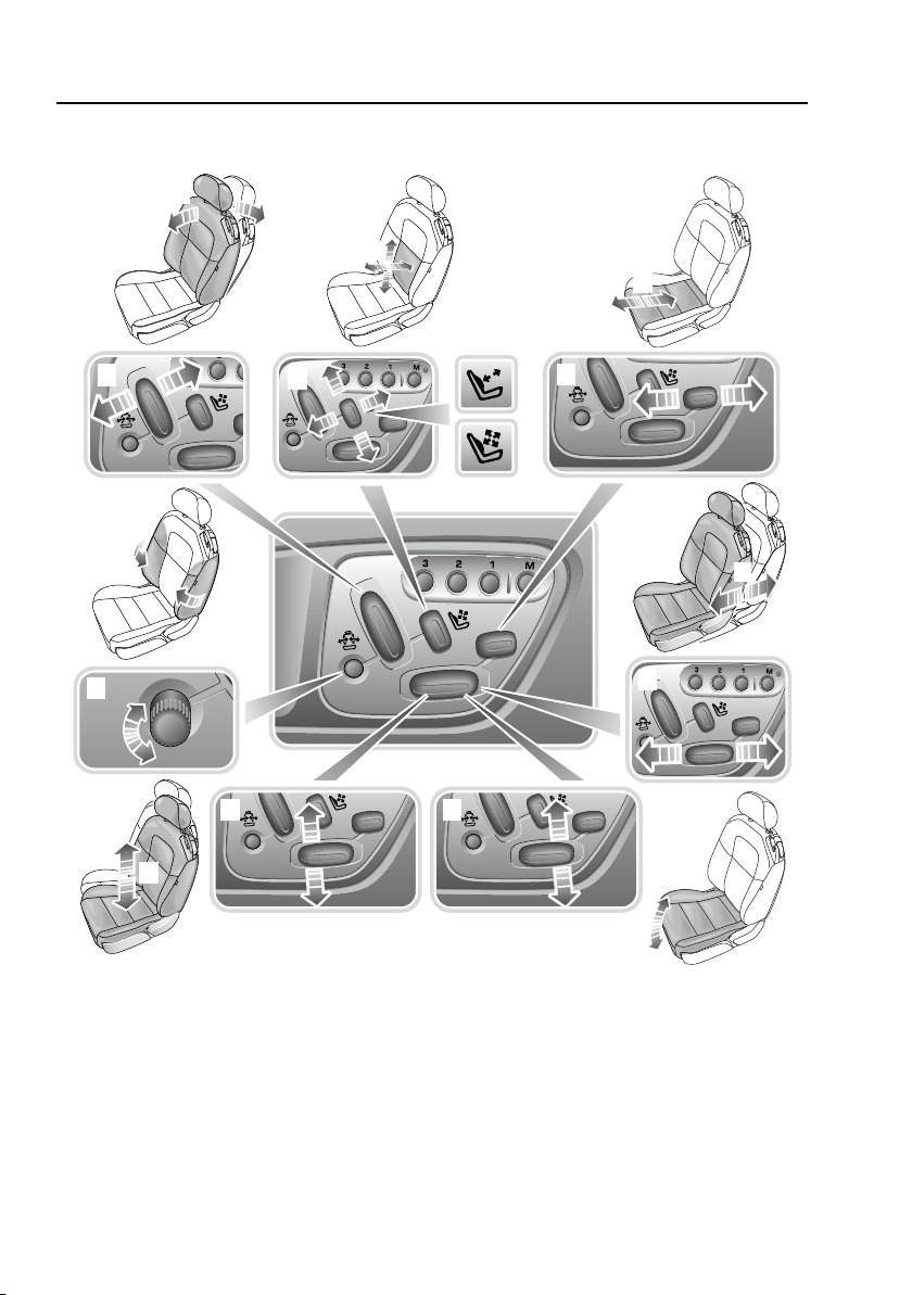
ELECTRIC SEATS
4
1
6
5
3
2
7
1
2
3
4
5
6
7
E90761
Seats
1. Seat back angle adjustment.
2. Lumbar support adjustment.
3. Cushion length adjustment.
4. Fore and aft adjustment.
5. Cushion front tilt adjustment.
6. Height adjustment.
7. Side bolster support adjustment.
30
Page 31

Seats
E90762
WARNINGS
Do not adjust the seat while the
vehicle is moving. Failure to follow
this instruction could potentially
cause personal injury or loss of vehicle
control.
Do not travel with the seatbacks
reclined steeply rearwards. Optimum
benefit is obtained from the seat belt
with the seatback angle set to no more than 30
degrees from the upright (vertical) position.
Failure to maintain the correct seatback angle
will reduce the effectiveness of the seat belts
and increase the risk of serious injury or death
in a crash.
Do not wedge objects (e.g. luggage)
between the front seat backrest and
the rear seat cushion.
The front seats are adjusted by switches on the
door.
Seat adjustments for three people may be
stored and recalled by the driver position
memory system. See MEMORY FUNCTION
(page 119).
Seatback tilt
The front seats tilt forward to allow access to
the rear seats.
To tilt the seat forward: Remove the seat belt
from the seat belt guide. Lift the lever and push
the seatback forwards to allow easy access.
The seatback will latch when returned to the
up-right position. Make sure that the seat belt
is returned to the seat belt guide. See
FASTENING THE SEAT BELTS (page 36).
31
Page 32

Seats
E90764
HEAD RESTRAINTS
WARNINGS
Head restraints are designed to
support the head, not the back of the
neck. The restraint must be
positioned correctly to restrain rearward
movement of the head in a collision. An
incorrectly adjusted head restraint increases
the risk of death or serious injury in the event
of a collision.
Adjust the head restraint so that the
top of the head restraint is above the
centre line of the head. An incorrectly
adjusted head restraint increases the risk of
death or serious injury in the event of a
collision. See SITTING IN THE CORRECT
POSITION (page 29).
Do not drive, or carry passengers with
the head restraints removed from
occupied seats. The absence of a
correctly adjusted head restraint increases the
risk of death or serious injury in the event of a
collision.
Never adjust the head restraints while
the vehicle is in motion. An incorrectly
adjusted head restraint increases the
risk of death or serious injury in the event of a
collision.
Each head restraint can be adjusted to give the
correct height for the seat occupant. They may
also be tilted.
• To lower: Press the button inwards and
push the head restraint into the seatback to
the required height.
• To raise: Pull the head restraint upwards.
• Swivel the head restraint forwards or
backwards until it is comfortably
positioned behind your head.
32
Page 33

Seats
Home
Audio
Climate
Phone
Navigatio
Vehicle
External
Left Right
20 21
C C
12
C
.0 .5
Radio
98.9 FM1
BC R1
A PTY
Valet
12 : 26 pm
E90765
Settings
Temp. sync.
External
12
C
Auto
Left Right
23 21
C .5 C
Auto
Econ
ate
.5
Auto
Climate
12 : 26 pm
E90766
HEATED SEATS
The front seat heating is activated via the
touch-screen main Home menu or the Climate
menu.
From the main Home menu, select either the
left-hand or right-hand seat icon and
repeatedly press to adjust for the required
temperature. With the engine running, first
press is fully on.
From the Climate main touch-screen select
either left-hand or right-hand seat icon and
repeatedly press to adjust for the required
temperature. With the engine running, first
press is fully on.
33
Page 34

Seat belts
E82942
GENERAL INFORMATION
WARNINGS
Seat belts are life saving equipment.
In a collision, occupants not wearing
a seat belt can be thrown around
inside, or possibly thrown out of the vehicle.
This is likely to result in more serious injuries
than would have been the case had a seat belt
been properly worn. It may even result in loss
of life.
The seat belts fitted to your vehicle
are designed for adults and larger
children. For their safety, it is very
important that all infants and children under
12 years of age are restrained in a suitable
child safety seat appropriate to their age and
size. See CHILD SEATS (page 47).
Make sure all occupants are securely
strapped in at all times - even for the
shortest journeys.
Do not adjust the seat belt while
driving.
Belts should not be worn with the
straps twisted.
Each belt assembly must only be used
by one occupant; it is dangerous to
put a belt around a child being carried
on the occupant’s lap.
WARNINGS
Seat belts are designed to bear upon
the bony structure of the body, and
should be worn low across the front
of the pelvis or the pelvis, chest and shoulders,
as applicable; wearing the lap section of the
belt across the abdominal area must be
avoided.
Seat belts should be adjusted as
firmly as possible, consistent with
comfort, to provide the protection for
which they have been designed. A slack belt
will greatly reduce the protection afforded to
the wearer.
Care should be taken to avoid
contamination of the webbing with
polishes, oils and chemicals, and
particularly battery acid. Cleaning may safely
be carried out using mild soap and water. The
belt should be replaced if webbing becomes
frayed, contaminated or damaged.
It is essential to replace the entire
assembly after it has been worn in a
severe impact even if damage to the
assembly is not obvious.
No modifications or additions should
be made by the user which will either
prevent the seat belt adjusting devices
from operating to remove slack, or prevent the
seat belt assembly from being adjusted to
remove slack.
Replacement and renewal of seat
belts should be carried out by Jaguar
Dealers/Authorised Repairers only.
Do not carry hard, fragile, or sharp
items between your person and the
seat belt. In an impact the pressure
from the seat belt on such items can cause
them to break, which in turn may cause death
or serious injuries.
34
Page 35

Seat belts
E90773
WARNINGS
When using seat belts to restrain
items other than occupants, take care
to make sure that the seat belts are
not damaged, or exposed to sharp edges.
The use of comfort clips or devices that would
create slackness in the seat belt system is not
advised.
Ensure that the webbing is midway between
the neck and the edge of the shoulder. Correct
tension is controlled by automatic retraction of
the reel.
Always wear seat belts without slack or twists,
since any slack in a seat belt reduces the
effectiveness of the belt and the level of
protection it can provide. For optimum
protection, the seat belts should fit tightly
around the body. Do not recline the front seats
excessively. Optimum benefit is obtained from
the seat belt with the seat back angle set to no
more than 30 degrees from the upright.
Note: If the vehicle is parked on unlevel
ground, the seat belt mechanism may lock.
This is not a fault, allow the seat belt to retract
a small amount before gently easing the belt
from its attachment to unlock it.
Front occupants only: The front seat belts are
equipped with an automatic webbing tension
relieving device. This device will reduce the
webbing loads experienced by the occupant
when the seat belt is correctly worn without
inducing any slack webbing.
The device is activated when, with the ignition
system on and the seat belt tongue engaged in
the buckle, webbing is extracted on occupant
lean forward (a series of clicks indicate the
range of movement with reduced tension).
If the engine is turned off with the seat belts
still fastened, a slight increase in seat belt
tension may be felt. This is normal, it is part of
the seat belt assembly’s tension control device.
Seat belt guide and retainer
To assist with both access and positioning of
the front seat belt webbing, a guide-retainer is
incorporated into each front seat.
When access to the rear of the vehicle is
required, remove the seat belt from the guide.
When returning the front seat to the previous
upright position ensure that the seat belt is
returned to the seat belt guide.
35
Page 36

Seat belts
E82905
Inertia reel mechanism test
• With the seat belt fastened, give the
webbing near the buckle a quick upward
pull. The buckle must remain securely
locked.
• With the seat belt unfastened, unreel the
webbing to the limit of its travel. Check that
the unreeling is free from snatches and
snags and then allow the belt to FULLY
retract.
• Partially unreel the webbing, then hold the
tongue plate and give it a quick forward
pull. The mechanism must lock
automatically and prevent any further
unreeling.
If a seat belt should fail any of these tests, you
should contact your Jaguar Dealer/Authorised
Repairer immediately.
SEAT BELT REMINDER
The belt reminder feature provides additional
reminders to the driver that an occupant’s seat
belt is unbuckled. A chime will sound
intermittently.
Note: Not all countries have the warning
chime.
Seat belt warning indicator
A warning indicator on the
instrument panel is illuminated
when:
• The driver’s seat belt is not fastened.
• A passenger is sitting in the front seat and
their seat belt is not fastened.
In some countries a warning signal sounds for
six seconds.
FASTENING THE SEAT BELTS
1. Draw the belt out smoothly, making sure
that the seat and your position on the seat
are correct. The belt should lay flat across
the pelvis, chest, and mid-point of the
collar bone between the neck and
shoulder.
2. With the seat belt correctly positioned,
place the metal tongue into the buckle
nearest to you. Press it in until a click is
heard.
Releasing the seat belts
To release the seat belt, press the red button.
Note: When releasing the seat belt it is
advisable to hold the belt before pressing the
release button. This will prevent the belt from
retracting too quickly.
36
Page 37

Seat belts
E82643
USING SEAT BELTS DURING
PREGNANCY
WARNINGS
Position the seat belt correctly for the
safety of the mother and unborn child.
Never wear just the lap strap, and
never sit on the lap strap whilst using just the
shoulder strap. Both of these actions are
extremely dangerous, and may increase your
risk of serious injury in the event of an accident
or during emergency braking.
Never place anything between you
and the seat belt in an attempt to
cushion the impact in the event of an
accident. It can be dangerous, and will reduce
the effectiveness of the seat belt in preventing
injury.
Position the lap strap comfortably across the
hips beneath the abdomen. Place the diagonal
part of the seat belt between the breasts and to
the side of the abdomen. Make sure that the
seat belt is not slack or twisted.
37
Page 38

Supplementary restraints system
PRINCIPLE OF OPERATION
Introduction
WARNINGS
High speed impacts may cause
serious injury or death irrespective of
safety features fitted to the vehicle.
Always drive with caution and consideration
for the vehicle's characteristics, road and
weather conditions and do not exceed any
speed limits in force.
Airbags inflate at high speeds and can
cause injuries. To minimise the risk of
injury, ensure that all vehicle
occupants wear correctly positioned seat
belts, sit correctly in the seats and position the
seats as far back as is practical.
Airbag inflation takes place
instantaneously, and cannot protect
against the effects of secondary
impacts. Under these circumstances the only
protection will be provided by a correctly worn
seat belt.
In the event of a collision, the airbag control
unit monitors the rate of deceleration caused
by the collision. This information is then used
to determine whether airbags should be
deployed.
Airbag deployment is dependent on the rate at
which the passenger compartment changes
velocity following the collision. The
circumstances affecting different collisions
(vehicle speed, angle of impact, type and size
of object hit, etc.) vary considerably and will
affect the rate of deceleration accordingly.
Advanced Restraint Technology System
(ARTS)
WARNINGS
Seat belts should be worn at all times,
by the driver and passengers in all
seating positions. The Advanced
Restraint Technology System (ARTS) cannot
provide protection in some types of impact.
Under these circumstances the only protection
will be provided by a correctly worn seat belt.
Phone systems should only be
installed by qualified persons familiar
with the operation of, and
requirements for, vehicles fitted with ARTS. If
you are in doubt, seek advice from your Jaguar
Dealer/Authorised repairer.
The airbags and seat belt pretensioners are
electrically controlled by an Advanced
Restraints Technology System (ARTS).
Various sensors determine the direction and
severity of an impact. The system analyses this
information then deploys only the appropriate
airbags (e.g. the side airbags where the impact
is on that side only).
38
Page 39

1
3
6
7
8
14
9
13
12
11
5
4
2
10
E90776
Supplementary restraints system
The ARTS components include :-
1. Dual front crash sensors.
2. Passenger dual stage airbag.
3. Passenger buckle pretensioner.
4. Passenger seat occupancy sensor.
5. Passenger belt tension sensor.
6. Passenger side head and thorax airbag.
7. Passenger side crash sensor.
8. Right-hand rollover protection bar
9. Left-hand rollover protection bar
10. Restraint control module.
11. Driver side crash sensor.
12. Driver side head and thorax airbag.
13. Driver buckle pretensioner.
14. Driver dual stage airbag (Steering wheel).
(convertible only).
(convertible only).
Note: The ARTS is not designed to operate as a
result of:
• Rear impacts.
• Minor front impacts.
• Minor side impacts.
• Heavy braking.
• Driving at very low speeds and over bumps
and pot holes.
Therefore, it follows that considerable
superficial damage to the vehicle can occur
without causing the airbags to deploy.
39
Page 40

Supplementary restraints system
1
2
3
E90780
Airbag location
1. Driver’s airbag.
2. Front passenger airbag.
3. Combined head and thorax side airbags.
OCCUPANT SENSING
WARNINGS
No objects whatsoever should be
attached to the centre cover of the
steering wheel, the passenger facia
panel, the sides of the front seats or the
interior trim. Placing objects on or over the
airbag inflation area may cause those objects
to be propelled inside the vehicle causing
serious injury to the occupants.
Occupants with disabilities who may
require the vehicle to be modified
should contact a Jaguar Dealer/
Authorised Repairer before any modifications
are made.
Several airbag system components
get hot after inflation. Do not touch
them after they have deployed.
WARNINGS
If an airbag has inflated, it will not
function again and must be renewed
immediately. Until a new airbag is
fitted, no protection is available in that
position.
In order to provide optimum protection this
vehicle is equipped with front and side airbags.
They are used in conjunction with the seat belts
to help protect occupants from upper body
(thorax) and head injuries.
40
Page 41

Supplementary restraints system
E90781
Occupancy classification sensor
A weight sensor is located in the front
passenger seat to determine the weight acting
upon the seat.
In certain conditions, e.g. where no passenger
is present, the appropriate airbags will be
deactivated and the airbag deactivation
indicator will illuminate. In a collision, these
airbags would not be deployed.
The occupancy weight sensor operates as
follows:
Passenger
occupancy
status
Completely
empty
Low weight
occupant or
object
Heavy occupant
or object
* It is possible to receive an intermittent
indicator illumination with an empty seat
condition.
Passenger
airbag status
Deactivated No*
Deactivated Yes**
Activated No
Indicator
active
This is part of the system’s adaptive behaviour,
and does not affect the status of the passenger
airbag. However, if the indicator becomes
permanently illuminated when the seat is
definitely empty and the seat belt is unbuckled,
then contact your nearest Jaguar Dealer/
Authorised Repairer immediately.
** In some cases, a small child placed in a
child seat will not activate the airbag
deactivation indicator (PASS AIR BAG OFF). If
this occurs, the passenger airbag status will be
as described previously for an empty seat, i.e.
passenger airbag not active, but the airbag
deactivation indicator will not illuminate.
• If the seat is empty and the seat belt
unbuckled, the front passenger airbag will
not be activated and the airbag indicator
will not be illuminated.
• If the seat is occupied by, for example, a
small child or object with the seat belt
buckled, the front passenger airbag will
not be activated and the indicator will be
illuminated.
• If the seat is occupied by a larger child or
adult, the front passenger airbag will be
activated and the airbag indicator will not
be illuminated.
Note: The occupancy sensing system is
designed to confirm that a front passenger is
properly seated as recommended:
• Always sit centrally in the seat, remaining
in contact with the seat back which for
comfort should be rearwards of the vertical
position.
• Adjust the seat to be as far back from the
facia as is practical. See ELECTRIC SEATS
(page 30).
• Always wear seat belts.
41
Page 42

Supplementary restraints system
E90782
Airbag deactivation indicator
The airbag indicator, on the centre console, is
associated with the deployment conditions for
front seat passenger airbags only.
Whenever the airbag indicator is illuminated,
the front passenger airbag will not be deployed
in the event of an impact. Where the airbags are
not deployed, protection is provided by the seat
belts.
Note: The airbag indicator will illuminate when
the ignition system initially comes on as part of
the warning lamp check and will extinguish
after approximately six seconds.
DRIVER AIRBAG
WARNING
The airbag is a supplementary
restraint system that provides
additional protection in a severe
impact only - it does not replace the need to
wear seat belts. For maximum safety
protection in all crash situations, a seat belt
must be worn.
Note: Provided front seat occupants are
correctly seated, with seat belts worn, the
airbag will give additional protection to the
chest and facial areas in the event of an
accident.
Both front airbags use a dual inflation
technology which means, if activated, the
airbags will deploy as appropriate for the
severity of frontal impact.
Airbag deployment
WARNINGS
Activation of an airbag creates dust,
causing possible breathing difficulties
for asthma sufferers or other people
with respiratory problems. If an airbag is
activated, any occupant who suffers from
breathing difficulties should; either leave the
vehicle as quickly as possible, or obtain fresh
air by fully opening the windows and doors.
Following inflation, some airbag
components are hot - do not touch
until they have cooled.
Even with airbag equipment fitted,
seat belts must always be worn
because an airbag will only provide
additional protection in certain types of frontal
collision. No protection is afforded against the
effects of rear impacts, or minor frontal
impacts.
Inflation and deflation takes place
instantaneously and will not provide
protection against the effects of
secondary impacts that can occur during
multiple vehicle collisions.
An inflating airbag can cause facial
abrasions and other injuries.
Minimise the risk of injury by
ensuring that front seat occupants are wearing
their seat belts and are seated correctly, with
the seat as far back as is practical.
42
Page 43

Supplementary restraints system
E91027
E91030
When an airbag inflates, a fine powder is
released. This is not an indication of a
malfunction. However, the powder may cause
irritation to the skin and should be thoroughly
flushed from the eyes and any cuts or
abrasions of the skin. After inflation, front and
side airbags deflate immediately (head airbags
deflate slowly). This provides a gradual
cushioning effect for the occupants and also
ensures that the driver’s forward vision is not
obscured.
Front protection
With a front impact of sufficient force,
the restraints system will trigger the front
airbag(s) and seat belt pretensioners, which
immediately tighten the seat belts.
The seat belts then ease, allowing the head and
chest to contact the inflated airbag. The airbag
absorbs the remaining energy of the impact
and then deflates rapidly via vent holes.
Front airbags are designed to inflate only in
frontal and near frontal collisions.
PASSENGER AIRBAG
WARNINGS
To minimise the risk of injury if the
airbag deploys, the front passenger
must sit as upright as possible with
feet on the floor and back against the seat
backrest. The seatbelt must be secured.
Do not put objects in front of or above
the dashboard where the passenger
airbag is located.
The passenger airbag is fitted and stowed
above the glove compartment. This panel is
marked AIRBAG. See OCCUPANT SENSING
(page 40).
43
Page 44

Supplementary restraints system
E91039
E91049
SIDE AIRBAGS
WARNING
To ensure that the side airbags are
fully effective do not sit too close to,
or lean against the door trim. The side
airbag could injure you as it deploys from the
side of the seat.
The airbags, in combination with the seat belts,
can help reduce the risk of severe injuries in the
event of a significant side impact collision.
When the seat mounted head and thorax airbag
inflates, it breaks through the seat bolster
stitching, giving protection to the side of the rib
cage and head of the driver or front seat
passenger.
The combined head and thorax side airbags are
designed to inflate only in a side impact
collision, unless the collision causes sufficient
lateral deceleration.
AIRBAG WARNING LAMP
The airbag warning indicator in the
driver's instrument panel will be lit
for approximately six seconds
when the ignition is turned on.
If the indicator remains on, it indicates a fault.
You should report the fault to a Jaguar
Dealer/Authorised Repairer immediately. It is
safe to drive the vehicle; however, in an
accident the airbags may not operate. See
WARNING LAMPS AND INDICATORS
(page 90).
WHIPLASH PROTECTION
Both front seats are equipped with Active Head
Restraints (AHR) which reduce the risk of neck
and spinal injury (whiplash) in the event of a
rear impact. When activated, the head restraint
moves upwards and forwards, supporting the
occupant's head.
After activation, the whiplash protection
mechanism automatically resets and does not
need to be replaced.
44
Page 45

Supplementary restraints system
E91055
E91056
ROLLOVER BARS
WARNINGS
Do not place any objects on top of the
system trim covers behind the rear
passenger head restraints as they
could prevent correct deployment of the
system.
Do not try to reset the system if it
deploys.
Do not let anyone sit on the top cover.
The Rollover Protection Device (RPD) consists
of two inverted U-shaped bars, that are
concealed underneath the rear parcel shelf, and
sensors that monitor the attitude of the vehicle.
AIRBAG LABELS
Airbag warning information is printed on the
driver’s and passenger’s sunvisor.
If the sensors determine that a risk of rollover
is imminent, the RPD will be deployed.
Note: If the convertible roof is closed when the
RPD is deployed, the bars are designed to
break through the rear screen.
If the RPD has been deployed, you should
proceed to your nearest Jaguar Dealer/
Authorised Repairer to have the vehicle
checked for any damage and to have the
system reset.
45
Page 46

Supplementary restraints system
AIRBAG SERVICE INFORMATION
WARNINGS
Do not attempt to service, repair,
replace, modify, or tamper with, any
part of the Advanced Restraints
Technology System (ARTS). This includes
wiring or components in the vicinity of ARTS
components. Doing so may cause the system
to trigger, or render the system inoperative,
either of which may result in death or serious
injuries.
Do not use any electrical test
equipment, or devices in the vicinity
of ARTS components or wiring. Doing
so may cause the system to trigger, or render
the system inoperative, either of which may
result in death or serious injuries.
All of the following operations should only be
carried out by a Jaguar Dealer/Authorised
Repairer, or suitably qualified person:-
• Removal or repair of any wiring or
component in the vicinity of any ARTS
components.
• Installation of electrical, or electronic,
equipment and accessories.
• Modification to the front or sides of the
vehicle exterior.
• Attachment of accessories to the front or
sides of the vehicle.
In the event of the vehicle being dismantled,
airbag module removal and disposal must be
carried out by a qualified person.
46
Page 47

Child safety
E91074
CHILD SEATS
General safety information
WARNINGS
Original text according to ECE
R94.01.
Extreme hazard! Do not use a
rearward facing child restraint on a seat
protected by an airbag in front of it!
Children must be restrained by a child
safety restraint that is suitable for
their weight and size.
The rear seat is the safest place for
properly restrained children.
WARNINGS
Do not install a rearward-facing child
seat in the front passenger seat
position since deployment of the
passenger facia airbag could cause death or
serious injury to the child. If, however,
you have no alternative but to place a child in
the front passenger seat, use only a
forward-facing child seat with the passenger
seat set fully rearward and in its lowest
position.
In many countries legislation governs how and
where children should be carried when
travelling in a vehicle.
It is the responsibility of the driver to comply
with all regulations in force in the country
where the vehicle is being used.
Holding a baby or child in a person’s arms is
not a substitute for a child restraint system.
In an accident, a baby or child held in this
manner can be crushed between the vehicle’s
interior and a restrained person.
The child can be injured by hitting the interior
or by being thrown from the vehicle during a
sudden manoeuvre or impact.
The seat belts fitted to your vehicle are
designed for adults and larger children. For
their safety, it is very important that all infants
and children under 12 years of age are
restrained in a suitable child safety seat
appropriate to their age and size. See CHILD
SEAT POSITIONING (page 49).
47
Page 48

Child safety
Choosing a suitable child seat
WARNING
Choose a child seat that sits securely
on the seat cushion and against the
seat back.
Before you buy a child seat, it is important to
note that your child’s weight, rather than age,
determines the type of seat that is required.
Jaguar strongly recommends the use of ISOFIX
seats. See ISOFIX ANCHOR POINTS (page 52).
Babies and small children who cannot sit up by
themselves should be carried in an approved
rear facing infant carrier, which should always
be installed in a rear seat position.
Jaguar recommends that a rear-facing seat
with a harness is used for as long as your
infant’s development allows.
Note: For approved child restraints, you should
contact your Jaguar Dealer/Authorised
Repairer.
Do not use a forward-facing seat until your
child is above the minimum weight of 9 kg
(20 lb) and able to sit up unaided. Up to the age
of two, a child’s spine and neck are not
sufficiently developed to avoid injury in a
frontal impact.
We strongly advise that you do not buy or use
a second-hand child seat. The seat may have
been used inappropriately, or involved in an
accident. In such circumstances, the seat may
not protect your child.
Always check that the child seat can be
mounted securely in the required position: if in
doubt, you should speak to your Jaguar Dealer/
Authorised Repairer.
Look for the following when selecting a child
restraint system:
• It should have a label certifying that it
meets the applicable regulations.
• Carefully read the instructions supplied
with the restraint. Be sure you understand
them and can install and use the device
properly and safely in the vehicle.
• Ensure that the child restraint system is
appropriate for the child’s weight and
development. See CHILD SEAT
POSITIONING (page 49).
48
Page 49

Child safety
CHILD SEAT POSITIONING
Suitability of each passenger seat position for the carriage of children up to 12 years of age or
1.35m (approx. 4.4 ft.) tall and the installation of child restraint systems.
Mass group (with approximate age) as
indicated on child restraint
0 = Up to 10 kg (22 lb) (birth to 9 months) X U**
0+ = Up to 13 kg (28 lb) (birth to 18 months) X U**
I = 9 to 18 kg (20 - 40 lb) (9 months to 4 years) UF* U
II = 15 to 25 kg (33 to 55 lb) (4 to 9 years) U* U
III = 22 to 36 kg (48 to 80 lb) (8 to 12 years) U* U
• U = Suitable for Universal category
restraints approved for use in this mass
group.
• UF = Suitable for forward-facing Universal
category restraints approved for use in this
mass group.
• X = Seat position not suitable for child
restraint in this mass group.
Note: * When installing a child restraint in the
front passenger seat, the front passenger seat
should be positioned fully rearward with the
cushion height adjustment set to front fully
down and rear fully up. Also the backrest must
be set as far forward as possible.
Note: ** Rear passenger space is restricted.
The front seat must be moved forward and
upwards to install any rearward facing infant
carrier. Care must be taken not to load any part
of the child seat or carrier when repositioning
the front seat. The space available for front seat
occupants will be reduced by the fitment of any
rearward facing infant carrier.
Note: If there is any doubt about which
age/weight category the child conforms to,
then always use a child seat or carrier
appropriate to the weight of the child.
Front passenger Rear
Automatic locking reel (ALR)
The rear passenger seat belts have an
automatic locking device for use with child
seats. When engaged, this device allows the
belt to be retracted (tightened) but not
extended. When used to secure a child seat,
therefore, the belt will automatically lock at any
point to which it has retracted.
1. Pull the seat belt all the way out to engage
2. Insert the metal tongue plate into the
3. To fix the seat firmly, retract the belt back
4. Push down on the child seat to ensure any
The above is a guide only. Depending on the
features of a particular child seat, e.g. forward
or rearward-facing, engage the locking device
before or after attaching the belt, as
convenient.
Unbuckling the belt and releasing the child seat
will allow the belt to resume its normal
operation.
Vehicle seating position
the locking device.
buckle. A positive click indicates that it is
safely locked.
to the reel, a ratchet operation may be felt
as the belt retracts. Continue to feed the
belt back onto the reel until it fits snugly
around the child seat.
slack is taken in by the mechanism.
49
Page 50

Child safety
E91105
General check list
Follow the check list each time your child
travels in the vehicle:
• Carefully follow the instructions provided
by the manufacturer of the restraint
system.
• Make sure your child falls into the correct
weight range for the seat.
• Always use the appropriate child restraints
and adjust harnesses for every child, every
trip.
• Avoid dressing your child in bulky clothing
and do not place any objects between the
child and the restraint system.
• Regularly check the fit of your child seat
and replace seats or harnesses that show
signs of wear.
• No child seat is completely child-proof.
Encourage your child not to play with the
buckle or harness.
• Never leave a child unsupervised in the
vehicle.
• Ensure your child does not exit the vehicle
from the side where there is traffic.
• Set your child a good example - always
wear your seat belt.
• Ensure that you have removed all slack
from the adult seat belt.
Child restraint top tether anchorages
WARNING
Child restraint anchorages are
designed to withstand only those
loads imposed by correctly fitted child
restraints. Under no circumstances are they to
be used for adult seat belts, harnesses or for
attaching other items or equipment to the
vehicle.
Coupe
The top tether anchorages are positioned on
the rear parcel shelf, under access covers, at
the centre-line of each rear seating position.
Lift the cover and connect the top tether to the
anchorage on the rear shelf. Adjust the length
of the top tether strap to hold the top of the
child seat against the vehicle seat back.
Ensure the child seat is securely fitted.
50
Page 51

Child safety
E91106
E91107
E91108
E91109
Convertible
Two child restraint anchorages are provided.
These are located under top tether covers in the
rear tonneau.
Refer to the child restraint manufacturer’s
fitting and operating instructions prior to
installation. Other child restraint devices may
not offer the same level of protection and it is
recommended that only the supplied device is
used in the convertible.
To expose a top tether:
2. Remove the top tether cover and close the
tonneau panel by briefly pressing and
holding the rear of the convertible
overhead console switch.
3. Ensure that the tonneau top tether cover is
safely stowed in the glove compartment.
1. Open the tonneau panel by briefly pressing
and holding the front of the convertible top
overhead console switch.
4. Attach the child restraint top tether clip to
the top tether anchorage bracket.
If an additional child restraint device is
required, please enquire through your
Authorised Jaguar Retailer or contact the
Jaguar Customer Service area on 1300 787
803.
51
Page 52

Child safety
BOOSTER CUSHIONS
In a situation where a child is too large to fit
into a child safety seat, but is still too small to
safely fit the three point belt properly, a booster
seat is recommended for maximum safety.
Follow the manufacturer's instructions for
fitting and use, then adjust the seat belt to rest
on the child's shoulder, not the neck.
ISOFIX ANCHOR POINTS
WARNINGS
If the restraint is not correctly
anchored, there is a significant risk of
injury to the child in the event of a
collision or emergency braking.
Child restraint anchorages are
designed to withstand only those
loads imposed by correctly fitted child
restraints. Under no circumstances are they to
be used for adult seat belts, harnesses or for
attaching other equipment or items to the
vehicle.
If removing a head restraint in order
to fit a child restraint, always secure
the head restraint when storing it. If
left loose in the vehicle it may cause death or
serious injury during sudden braking or an
impact.
The rear seats of your vehicle are fitted with
anchor bars that comply with International
Standard Organisation regulations (ISO). They
allow the ISOFIX child seats to be secured
directly and easily to the vehicle body without
the use of adult seat belts.
The ISOFIX system reduces the likelihood of
incorrect fitting and is also quicker and simpler
to use.
When installing either a front or rear facing
ISOFIX child seat in the rear seats, the seat
directly in front of the rear seat being used,
must be set in its most forward position and
with the seat in its most upright position.
Therefore, it is not recommended that the front
seat is occupied while using an ISOFIX child
seat.
52
Page 53

Child safety
ISOFIX child seat positioning
Mass group* Size classes Fixtures Vehicle ISOFIX
positions
Rear seats
Carrycot F/G ISO L1/L2 X
0 = Up to 10 kg (26.8 lb) E ISO R1 IL*
0+ = Up to 13 kg (34.8 lb) E ISO R1 IL*
0+ = Up to 13 kg (34.8 lb) C/D ISO R2/R3 X
I = 9 kg to 18 kg (24 lb to 48 lb) C/D ISO R2 X
A/B ISO F2/F3 X
B1 ISO F2X IL*
II = 15 kg to 25 kg (40.2 lb to 67 lb) - Not Applicable Not Applicable
III = 22 kg to 36 kg (59 lb to 96.5 lb) - Not Applicable Not Applicable
• IL = Suitable for particular ISOFIX child
restraint systems (CRS) given in the
attached list*. These ISOFIX CRS are those
of the specific vehicle, restricted, or
semi-universal categories.
• X = ISOFIX positions not suitable for
ISOFIX child restraint systems in this mass
group and/or this size class.
• * = Child seats recommended for use in
these locations are Britax or Roemer Duo
Plus Isofix, Britax Cosy-tot Isofix or
Roemer Baby-safe Isofix.
Note: ISOFIX anchorages are provided for rear
seats only. ISOFIX child restraints should be
securely attached, following the
manufacturer's instructions, at these locations
only.
53
Page 54

Child safety
E91111
E91112
Installing an ISOFIX child seat
CAUTION
Always follow the manufacturer’s
instructions supplied with the ISOFIX
child seat.
The anchorage loops are accessible through
two trimmed apertures at the back of the rear
seat cushion.
Their location is highlighted by the small tag
labels with a child seat graphic. The anchorage
loops are located approximately 60 mm (2.5
inches) below each label. Pull back the side of
the trim to reveal the aperture and the
anchorage loops.
Fit the seat as follows (the following is to be
considered only as a guide):
1. Push the adult seat belt buckles into their
stowage recesses, to ensure they do not
interfere with the fitment of the child seat.
2. Make sure there is nothing obstructing the
seat mounting mechanism at the
anchorage points.
3. Fully extend the two attachment legs on
the child seat. Ensure the hook at the end
of each leg is open.
4. Position the attachment legs just in front of
the trimmed apertures for the ISOFIX
anchorage loops. Push the anchorage leg
through the trimmed aperture to engage
with the vehicle’s anchorage loop. There
should be an audible click.
5. Repeat Step 4 for the child seat’s second
anchorage leg.
6. Using firm and even pressure on both
sides, push the child seat rearwards until it
is secured firmly against the seat back.
Make sure you do not trap the top tether
strap behind the child seat.
7. If your vehicle is fitted with top tether
anchorage brackets, make sure that the
top tether strap is secured.
8. As a final check, firmly pull both sides of
the seat to confirm that it is correctly
locked into position.
54
Page 55

Child safety
Removing the ISOFIX seat
To remove the ISOFIX child seat, press the
locking button on each side of the seat to
release anchorage legs. If your vehicle is fitted
with top tether anchorages, undo the top tether
strap and lift the child seat from the vehicle.
55
Page 56

Pedestrian protection
E91119
PRINCIPLE OF OPERATION
The pedestrian protection system has been
designed to reduce lower leg and head injuries
in the event of a frontal collision with a
pedestrian.
The bumper includes energy absorbing foam
and plastics in its construction to reduce leg
injuries and sensors that detect the collision
with a pedestrian.
Deployment
During a pedestrian collision, the sensors
initiate a bonnet deployment system that
releases the bonnet latches and raises the rear
edge of the bonnet by approximately 130 mm
(5.1 inches).
This increases the gap between the bonnet and
the components within the engine
compartment e.g. engine, suspension etc. This
increased gap creates a cushion which reduces
injuries caused to the pedestrian.
The bonnet deployment system is active only
when the ignition is on and the vehicle is driven
between the speeds of approximately 15 km/h
(9 mph) and 45 km/h (28 mph).
AFTER DEPLOYMENT OF THE
PEDESTRIAN PROTECTION SYSTEM
The bonnet will remain in its unlatched position
and cannot be relatched.
The vehicle must be stopped as soon as it is
safe to do so.
The hazard warning lamps will be activated and
can only be switched off by pressing the engine
START/STOP button to turn the engine off and
on again.
The warning message CHECK PEDESTRIAN
SYSTEM will appear on the message centre
and the vehicle should be transported to the
nearest Jaguar Dealer/Authorised Repairer.
The vehicle must not be driven when the
bonnet has been deployed. See DRIVING
AFTER A COLLISION (page 224).
Note: If the warning message CHECK
PEDESTRIAN SYSTEM appears on the
message centre when there has been no
deployment of the bonnet, the vehicle can be
driven and should be taken to the nearest
Jaguar Dealer/Authorised Repairer
immediately.
If any significant damage occurs to the front
bumper it should be inspected by a Jaguar
Dealer/Authorised Repairer as soon as
possible.
56
Page 57

Steering wheel
E91122
ADJUSTING THE STEERING WHEEL
WARNING
Never adjust the steering wheel
position whilst the vehicle is in
motion. Doing so will reduce control
of the vehicle, and may cause unpredictable
steering movements.
CAUTION
Do not use steering wheel mounted
security devices since movement of the
steering wheel in entry or exit mode could
result in damage to the vehicle (e.g. the
windscreen) or possible injury to the
occupant.
The steering wheel can be adjusted for tilt and
reach.
1. Turn the switch to the COLUMN or AUTO
position.
2. Move the switch forwards or backwards to
adjust reach.
3. Move the switch up or down to adjust tilt.
Three steering wheel positions can be stored
and recalled by the driver position memory
system. See MEMORY FUNCTION (page 119).
The message centre will indicate which switch
position has been selected, by displaying the
message COLUMN ADJUST or COLUMN
ADJUST AUTO.
Entry and exit mode
Entry and exit mode provides automatic
movement of the steering column to allow
easier entry to or exit from the vehicle.
Entry and exit mode is selected by setting the
steering column adjustment switch to the
AUTO position.
Exit: If the ignition system is in the
convenience mode position and the driver’s
door is opened, the steering column will move
to the uppermost tilt position, unless already in
that position.
Entry: When the door is closed and the
START/STOP button is pressed, the steering
column will return to the previous position.
Notes on entry and exit mode operation
• If the steering column switch is moved
away from AUTO whilst the steering
column is tilted away, the steering column
will move back to its previous position
when the driver’s door is closed and the
START/STOP button is pressed.
• If the steering column is adjusted during
entry and exit operation, steering column
movement will stop.
57
Page 58

Steering wheel
E91123
Home
Audio
Climate
Phone
Navigation
Vehicle
External
Left Right
20
C C
12
C
.0
Radio
98.9 FM1
BBC R1
TP TA PTY
Valet
12 : 26 pm
E91124
Settings
Temp. sync.
External
12
C
Auto
Left Right
23
C C
Auto
Econ
Climate
.5
Auto
Climate
12 : 26 pm
E91125
1 2
4 3
E91129
HORN
The dual tone horn is operated by pressing the
centre pad on the steering wheel.
The horn also operates as a warning horn if the
vehicle alarm system is activated.
HEATED STEERING WHEEL
The heated steering wheel is activated via the
touch-screen from the Home menu.
The heated steering wheel can also be activated
in the same way via the Climate menu.
AUDIO CONTROL
With the engine running, touch the steering
wheel icon to turn the steering wheel heater on
or off.
1. Increase or decrease volume.
2. Cycle through preset radio stations or next
CD track. A short press will seek up or
down to next preset station or next CD
track. Press and hold for two seconds to
select next strong radio station or next CD.
3. Cycle through radio FM, AM and CD
changer. Press and hold for two seconds
to select Phone Ready mode.
4. Select mute or answer phone call when
ringing.
58
Page 59

Steering wheel
1
23
E91130
CRUISE CONTROL
The cruise (speed) control system can be used
by the driver to maintain a selected vehicle
speed without the driver having to use the
accelerator.
Controls on the steering wheel allow the driver
manual control of the system.
1. Speed adjustment control: The thumb
wheel is used to engage cruise control
initially. It is also used to increase or
decrease the set speed.
2. CANCEL: cancels cruise control but retains
the set speed in memory.
3. RESUME: engages cruise control after it
has been cancelled.
For further information:
See USING CRUISE CONTROL (page 145).
See USING ACC (page 147).
59
Page 60

Lighting
E91137
E91138
E91139
E91140
E91141
LIGHTING CONTROL
Note: If the ignition system is off and the lamps
are left on, the message centre will display
LIGHTS ON.
The exterior lamps are controlled by the
left-hand column stalk switch.
The rotary collar on the stalk has three
positions for turning the exterior lamps on or
off and positions for autolamps and exit delay.
These are:
Off
All exterior lamps off (except vehicles provided
with daylight running lamps).
Headlamp flash: Pull the switch towards the
steering wheel and release, to flash the high
beam on and off. The high beam will remain on
for as long as the switch is held.
Side lamps
Switches on the side, tail and number plate
lamps and marker lamps required by local
legislation. The instruments will also be lit.
Headlamps
With the ignition in convenience mode, select
this position to switch on the headlamps
High beam: With the headlamps on, push the
switch away from the steering wheel to switch
to high beam.
The blue warning indicator on the instrument
panel will illuminate.
To turn high beam off and return to low beam,
pull the column switch towards the steering
wheel.
Note: If the rotary control switch is turned ot
the OFF position, with high beam still activated,
the headlamps will be extinguished. The
headlamps will illuminate at high beam when
the headlamps are turned on again.
60
Page 61

Lighting
E91142
E91143
Autolamps
A light sensor, mounted on the front of the
facia, monitors exterior light levels and
automatically switches the side lamps and low
beam headlamps on or off.
The ignition system must be on for full
automatic light operation.
When light fades towards dusk, the side lamps
and headlamps will switch on automatically.
At dawn, as light increases, the side lamps and
headlamps switch off automatically.
Do not cover the sensor and keep the
windscreen clean. Obstructing the light in this
area of the sensor may lead to unwanted
operation of the side lamps and headlamps.
Windscreen wiper detection
This function only operates when autolamps is
selected. The side lamps and headlamps will
switch on automatically if the windscreen
wipers are switched on for 20 seconds or
more. Once the windscreen wipers are
switched off, the side lamps and headlamps
will automatically switch off two minutes later.
Autolamps with exit delay
Three settings on the rotary collar set the time
that the headlamps will remain on after the
driver’s door has closed:
• 30 seconds.
• 60 seconds.
• 120 seconds.
The message centre will display the change set
delay AUTOLAMP DELAY X:XX or AUTOLAMP
DELAY OFF when the autolamp delay function
has been turned off.
Note: If the lamp switch rotary collar is in the
AUTO position there will be no exit delay and
the headlamps will turn off when the ignition
system is off.
61
Page 62

Lighting
E91155
Daylight running lamps
In certain countries it is a legal requirement for
the lamps to be on during the hours of daylight.
With the rotary collar in the OFF position, low
beam headlamps, side lamps, tail, number
plate lamps and, where fitted, side marker
lamps will switch on automatically with the
following conditions:
• The ignition is in on (Scandinavia only).
• The vehicle gear selector out of P (Park).
• The parking brake is not applied (is
released).
Door guard and puddle lamps
Door guard lamps are fitted to each door to
give warning of an open door to passing
vehicles. Puddle lamps illuminate the step out
area at night.
Each lamp comes on automatically when the
door is opened. If the door is left open the
lamps remain on for approximately 15 minutes
after returning from convenience mode to
power off.
Condensation
In certain circumstances, misting may occur
on the inside of a lamp lens. This is caused by
natural changes in environmental conditions.
This misting is not detrimental to lamp
performance and will clear during normal
usage.
FRONT FOG LAMPS
The fog lamps can only be switched on when
the ignition system is on and when side lamp
or low beam is selected.
With the lighting control switch in side lamp or
low beam position, press the switch to turn on
the front fog lamps. Pressing the switch again
will turn off the front fog lamps.
Note: The rear fog lamps will be turned off
when the ignition system is turned off, but will
need to be reselected when the ignition system
is turned on again.
The front fog lamps should only be used when
visibility is severely restricted by fog.
62
Page 63

Lighting
E91156
E91157
REAR FOG LAMPS
Depending on market, the single rear fog lamp
is located on either the rear left-hand or
right-hand side of the vehicle.The rear fog lamp
can only be switched on if the low beam
headlamps are on or if the side lamps and front
fog lamps are switched on.
Press the switch to turn on the rear fog lamp.
Pressing the switch again will turn off the rear
fog lamp.
Note: The rear fog lamps will be turned off
when the ignition system is turned off, but will
need to be reselected when the ignition system
is turned on again.
The rear fog lamp should only be used when
visibility is severely restricted by fog.
HEADLAMPS - DRIVING ABROAD
The tourist levers allow you to adjust the
headlamps to the correct beam pattern for
driving in left or right-hand drive territories.
When new, the levers will be set to the correct
position for the country in which the vehicle is
sold. To change the pattern for driving on the
other side of the road, move the levers to the
opposite position.
To adjust the headlamp beam pattern:
Note: When changing the beam pattern,
ensure that you change the lever position on
both headlamps.
1. Remove the headlamp unit. See
CHANGING A BULB (page 68).
2. Twist the headlamp unit rear cover
counterclockwise and lift off.
3. Locate the adjustment lever, as shown.
4. Move the lever to the opposite position.
5. Refit the headlamp rear cover and the
headlamp unit. See CHANGING A BULB
(page 68).
Remember to place the levers back in their
original position when you have returned to
your country of origin.
63
Page 64

Lighting
E91158
1
2
E91159
HEADLAMP LEVELLING
Headlamp levelling is adjusted automatically.
Automatic levelling of the headlamps is a
feature which avoids dazzling oncoming
drivers. A control unit adjusts the aim of the
lamps to account for acceleration, deceleration
and vehicle load conditions.
HAZARD WARNING FLASHERS
Press the switch to turn the hazard warning
lamps on. When the hazard warning flashers
are operating, the indicator warning lamps will
flash in time with the hazard warning flashers.
Press again to turn the hazard warning flashers
off.
Hazard warning flashers should only be used in
an emergency, to warn traffic of a vehicle
breakdown or approaching danger.
Note: Hazard warning flashers can be used
when the ignition is on or off.
ADAPTIVE FRONT LIGHTING SYSTEM
(AFS)
The Adaptive Front Lighting System (AFS) is
designed to give the driver improved visibility
under varying driving conditions.
1. Light spread of a vehicle not fitted with
AFS.
2. Light spread of a vehicle fitted with AFS.
The main light source consists of bi-functional
(high and low beam) xenon projector units.
The projector units are swivelled left or right to
improve the light spread on bends in the road.
64
Page 65

Lighting
50
100
3
4
E91160
1
2
E91161
Cornering or static bending lamps
Additional lighting comes from the cornering
or static bending lamps which are angled
outwards from the centre line of the vehicle.
These lamps broaden the beam of the
headlamps when cornering during normal
night driving.
Bi-Xenon lamps (3) provide significantly
improved visibility over halogen lamps (4).
They also react dynamically in the vertical
plane to the vehicle’s braking or acceleration to
maximise headlamp performance.
The units operate when the engine is running
and the lighting control switch set to
headlamps or AUTO, if the ambient light has
fallen below a preset level.
The system takes inputs from the vehicle’s
road speed, steering angle to determine the
amount of horizontal swivel. The amount of
swivel is highest at low speed, manoeuvring
speeds and reduces as speed increases.
If reverse gear is selected, the lamps return to
the central position and the swivelling
capability is disabled.
When the engine is started, the headlamps can
be seen to swivel as they initiate a
self-calibration cycle for a few seconds.
1. Light spread of a vehicle not fitted with
static bending lamps.
2. Light spread of a vehicle fitted with static
bending lamps.
The system switches on the lamp if it has
received an input from the vehicle’s direction
indicators. Only the lamp on the same side as
the operating direction indicator illuminates.
65
Page 66

Lighting
E91163
As the system is ignition based, the lamp will
not stay on, even if the vehicle is parked (and
the ignition switched off) with the direction
indicator lever in the operating position.
Note: Excessive rotation of the steering wheel
while the ignition system is off, may cause
incorrect calibration of the static bending
lamps. In extreme situations, the lamps may
operate earlier than previously experienced.
However, correct calibration of the lamps is
automatically re-established within 30 seconds
of the vehicle being driven.
If a system fault is detected the
headlamps will attempt to move to
the central position, and remain
stationary. The AFS warning indicator will
illuminate to indicate that a fault is present.
If the warning indicator illuminates, contact
your Jaguar Dealer/Authorised Repairer as
soon as possible.
DIRECTION INDICATORS
The direction indicators are operated using the
indicator stalk. Move the stalk up or down, to
indicate a right or left turn. A green warning
indicator will flash in the instrument panel.
The indicators will operate three times (e.g. to
indicate a lane change) if the stalk is briefly
pushed up or down. Lane change flash can be
disabled or enabled by a Dealer/Authorised
Repairer.
Note: Should a direction indicator bulb fail, the
corresponding green warning indicator will
flash at twice the normal rate and the audible
ticking will sound at twice the normal rate.
66
Page 67

Lighting
2 1 2
3
E91164
INTERIOR LAMPS
1. Courtesy lamp and footwell lamps.
2. Left and right-hand reading and map
lamps.
3. Centre console illumination.
Interior lighting comprises, front overhead
courtesy lamps, two front reading and map
lamps and front puddle lamps. Vanity mirrors,
glove compartment, footwell and luggage
compartment lamps are also provided.
Press the centre switch (1) in the front roof
console to turn the courtesy lamps, puddle
lamps and footwell lamps on. A second press
turns the lamps off. The lamps also operate to
illuminate the vehicle interior when a door is
opened.
The interior courtesy lamp and footwell
lamps can be de-activated by pressing the
centre switch for more than two seconds. The
courtesy lamp will flash, then switch off.
The courtesy lamp and footwell lamp will come
on again when the lamp switch is pressed
again for more than two seconds.
The centre console area is illuminated by a
small lamp from the overhead console (3). This
is on whenever the side lamps are on and can
be controlled by the dimmer switch.
Reading lighting
The reading and map lamps are turned on and
off by individual switches (2) on the front
overhead console.
Illuminated entry and exit
The interior lamps will gradually illuminate
when a door is opened and go out when the
engine is started or approximately 30 seconds
after the last door is closed. If any door is left
open, the lamps will fade off approximately 15
minutes after returning from convenience
mode to power off.
When the vehicle is unlocked, the courtesy
lamps will come on at maximum brightness for
approximately 30 seconds, if a door is not
opened.
With the engine running, opening any door will
put on all interior lamps, they will go out
immediately after the last door is closed.
Glove compartment
The glove compartment will illuminate when
opened.
Luggage compartment lighting
The luggage compartment will be illuminated
when opened.
Battery saver
To prevent battery discharge, the interior, glove
compartment, luggage compartment, reading,
map and vanity lamps will automatically turn
off after approximately 15 minutes, once the
ignition is turned off.
67
Page 68

Lighting
21 3 4 5
E91167
CONVENIENCE HEADLAMPS
This feature is activated by
pressing the headlamp icon button
on the Jaguar Smart Key. See
USING THE REMOTE CONTROL (page 14).
The headlamps will remain on for 25 seconds
or until the button is pressed again, or until the
engine START/STOP button is pressed.
CHANGING A BULB
General information
CAUTION
Alway replace bulbs with the correct
type and specification. If you are in any
doubt contact your Jaguar Dealer/Authorised
Repairer for advice.
Seek advice about the correct
disposal of Xenon lamp units from
a Jaguar Dealer/Authorised
Repairer, or your local authority.
The message centre will display a message
indicating which bulb requires to be replaced.
Before renewing bulbs, switch off the ignition
system and lamp switches.
To change the bulbs within the headlamp and
taillamp, the complete units require to be
removed from the vehicle.
Note: In most countries it is illegal to use a
vehicle with a defective exterior lamp bulb.
Headlamp unit
WARNINGS
Replacement or maintenance of
Xenon lamps should be carried out by
a Jaguar Dealer/Authorised Repairer.
Used Xenon lamp units contain
mercury which is hazardous and can
be injurious to health.
Xenon lamp units operate at a high
temperature. If they have recently
been in use, allow sufficient time for
them to cool down before touching them.
The Xenon system generates up to
28,000 volts and contact with this
voltage could lead to a fatality. Ensure
that headlamps are switched off before
working on the system.
1. Side marker.
2. Direction indicator.
3. Low and high beam projector unit.
4. Side lamp.
5. Cornering lamp.
68
Page 69

Removal of the headlight unit
5 3
1
4
2
2
E91168
Lighting
1. Remove the lower headlamp securing bolt
located in the front of the wheel arch.
For improved access, turn the steering
wheel to the left when removing the
right-hand headlamp, and to the right
when removing the left-hand headlamp.
2. Open the bonnet and remove the upper
securing bolts.
3. Disconnect the headlamp powerwash
connector by pressing the button and
pulling the pipe apart, some washer fluid
may drain from the pipe when it is
disconnected.
4. Release the headlamp locating peg by
lifting the tongue upwards.
5. Carefully ease the headlamp unit forward,
to gain access to the wiring multi-plug
connector. Release the connector by
pressing upwards on the release button
and pull the wiring multi-plug from the
headlamp. Place the headlamp unit on a
flat surface covered in a soft material to
prevent damage to the lens.
69
Page 70

Lighting
3
E91169
2
3
E91171
Refitting the headlamp unit
1. Reconnect the wiring multi-plug
connector.
2. Offer up the unit into position.
3. Ensure that the locating peg is fitted into
the in-board locating hole.
4. To secure the headlamp unit, first secure
the wheel arch screw, then repeat the
removal procedure in the reverse order,
ensuring that the powerwash pipe is
reconnected.
Note: After the replacement of any bulb and the
fitting of the headlamp unit, the aim of the
headlamps should be checked by a Jaguar
Dealer/Authorised Repairer.
Front direction indicator lamp
1. Remove the headlamp unit.
2. Twist the bulb holder counterclockwise
and pull out the bulb complete with the
electrical connector.
3. Twist and pull the bulb out of the bulb
holder.
4. Insert the new bulb (PY21W) and repeat
the above procedure in reverse order.
70
Page 71

Lighting
2
4
E91172
3
2
4
5
E91173
Side lamp
1. Remove the headlamp unit.
2. Twist and lift off the side domed cap.
3. Pull out the bulb complete with bulb
holder.
4. Pull the bulb out of the bulb holder.
5. Insert the new bulb (W5W) and repeat the
above procedure in the reverse order.
Ensure that the cover is fitted correctly to
retain the water tightness.
High and low beam projector unit
CAUTION
It is strongly advised that the High
Intensity Discharge (HID) Xenon low
and high beam project unit (D1S35W) should
be replaced by a Jaguar Dealer/
Authorised Repairer.
1. Remove the headlamp unit.
2. Twist and lift off the rear domed cap.
3. Twist the bulb unit counterclockwise to
unlock it. Pull the bulb unit clear of the
headlamp unit.
4. Press the electrical connector release lever
and disconnect the bulb unit.
5. Press the bulb unit adaptor ring catch and
remove the adaptor ring from the bulb unit.
6. Secure the bulb unit adaptor ring onto the
new bulb (D1S35W) and repeat the above
procedure in the reverse order. Ensure that
the cover is fitted correctly to retain the
water tightness.
71
Page 72

Lighting
2
3
4
E91174
Cornering or static bending lamp
CAUTION
Halogen bulbs will be damaged if
touched by hand or contaminated with
oil or grease. It is important to use clean
gloves or lint free cloth when handling a bulb
which is to be used again. A contaminated
bulb may be cleaned with methylated spirit
before refitting.
4. To release the bulb unit, lift the two
catches of the electrical connector, then
pull to remove the bulb unit.
5. Insert the new bulb unit (H8) and repeat
the above procedure in the reverse order.
Ensure that the cover is fitted correctly to
retain the water tightness.
Rear fog, reverse and high level brake
lamps
WARNING
LED lamp units operate at a high
temperature. If they have recently
been in use, allow sufficient time for
them to cool down before touching them.
These lamps are LED units and are integral to
the luggage compartment lid. They should be
replaced by a Jaguar Dealer/Authorised
Repairer.
1. Remove the headlamp unit.
2. Twist and lift off the side domed cap.
3. Twist the bulb holder counterclockwise to
unlock, then pull out the bulb complete
with electrical connector.
72
Page 73

Lighting
1
3
E91175
E91176
1
3
Number plate lamp
1. Insert a wide flat bladed suitable tool, twist
and lever the lens out of the surround
panel. Ensure that the lens moves to the
outer edge of the surround panel to release
the securing tangs.
2. Twist and pull out the bulb holder
complete with bulb.
3. Pull the bulb out of the bulb holder.
4. Insert the new bulb (W5WL).
5. Refit the lens by locating the outboard
securing tangs first and then pressing it
firmly into the recess until it clicks.
Side repeater lamp
1. Push the lens firmly towards the rear of the
vehicle and withdraw the lamp unit from
the wing panel.
2. Twist to release the bulb holder from the
lens unit.
3. Pull the bulb out of the bulb holder.
4. Insert the new bulb (WY5W) and repeat
the above procedure in the reverse order.
73
Page 74

Removal of the rear lamp unit
1
3
2
E91177
Lighting
The rear lamp unit contains four lamp bulbs
and it is necessary to remove the unit from the
vehicle in order to change any of the bulbs.
1. Open the luggage compartment. For the
right-hand side unit, detach the interior
lamp unit from the trim panel (Convertible)
or the vent trim panel (Coupe) and remove
the two rear lamp unit securing nuts. For
the left-hand side unit, detach the vent trim
panel and remove the rear lamp unit
securing nut.
2. Firmly pull the rear lamp unit trim panel
from the vehicle.
3. Firmly pull the rear lamp unit away from
the vehicle and disconnect the wiring
multi-plug connector. Remove the lamp
unit from the vehicle and place the unit on
a flat surface covered in a soft material to
prevent damage to the unit’s lens. Each
bulb is now accessible by twisting off its
bulb holder and removing the bulb.
4. Insert a new bulb and repeat the above
procedure in the reverse order.
74
Page 75

Lighting
1 2
3
4
E91178
Rear lamp unit replacement bulbs
1. Side marker.
2. Direction indicator.
3. Stop and Tail.
4. Tail.
75
Page 76

Lighting
BULB SPECIFICATION CHART
CAUTION
Before attempting to replace a bulb
make sure that both the affected lamp
and the vehicle's ignition system are turned
off. If the circuit is live a short circuit can occur
which may damage the vehicle's electrical
system.
Lamp Specification Power
(Watts)
Xenon headlamp
(Low and High
beam).
Front side lamps. W5W 5
Front direction
indicators.
Cornering lamps. H8 55
Side repeater
lamps.
Stop/tail lamps. P21/5W 21/5
Number plate
lamps.
Rear direction
indicators.
Rear side marker
lamps.
Tail lamp. W5W 5
D1S35W 35
PY21W 21
WY5W 5
W5WL 5
PY21W
Silver Vision
W5W 5
21
76
Page 77

Wipers and washers
1
2
3
4
5
E91182
E91183
E91184
WINDSCREEN WIPERS
CAUTIONS
Do not operate the windscreen wipers
on a dry screen. The drag on the wiper
mechanism may cause damage.
In freezing or very hot conditions ensure
that the wipers have not stuck to the
windscreen before operating. The drag on the
wiper mechanism may cause damage.
Remove any snow, ice or frost from the
windscreen, around the wiper arms and
blades and the screen scuttle before operating
the wipers. Snow and ice can cause damage to
the wiper mechanism if not cleared.
Note: If the wiper blades become stuck or
jammed, an electronic cut-out may temporarily
stop the wipers. If this happens, switch off the
wipers and the ignition. Clear any obstructions
and free the wiper blades, before attempting to
switch on the ignition.
Wiper operation
Intermittent variable delay
When intermittent wipe (2) is selected, the
delay between wipes can be varied by turning
the rotary collar (5) to the required delay
position. Rain sensor wiper operation is
selected by turning the collar to AUTO.
Note: If configured, the delay period for each
collar position (excluding AUTO), automatically
increases and decreases with vehicle speed.
Flick wipe
1. Windscreen wipers off and parked.
2. Intermittent wipe.
3. Normal wipe speed.
4. Fast speed wipe.
5. Intermittent wipe rotary collar.
Pull the stalk towards the steering wheel for a
single wipe. Holding the stalk in this position
will operate the wipers continuously at normal
speed until released.
77
Page 78

Wipers and washers
E91189
Speed dependent mode
If speed dependent mode is configured, the
operation of all wiper modes will be affected by
the vehicle speed.
Speed dependent mode becomes active when
the wipers are operating and the vehicle speed
exceeds 10 km/h (6 mph). If the vehicle
subsequently comes to a stop, the wiper
automatically changes to the next lowest
operating speed. When the vehicle starts
moving again, the original wiper speed setting
is automatically restored.
Speed dependent mode can be configured by
your Jaguar Dealer/Authorised Repairer.
RAIN SENSOR
CAUTIONS
Ensure that AUTO is not selected when
entering a car wash or damage to the
wiper blades or arms can occur as they will
operate in the car wash.
During frosty conditions ensure that
AUTO is not selected before operating
the ignition system as damage to the wiper
blades can occur when the windscreen is
frozen.
When AUTO and intermittent wipe (2) are
selected, the wipers will automatically operate
when rain falls on to the windscreen, or when
moisture is present.
For the wipers to operate, the ignition must be
on.
Note: When starting a journey with a wet
windscreen, the rain sensing wipers may not
operate immediately when the ignition is
switched on. Therefore, a flick wipe should be
used to clear the windscreen of any moisture.
WINDSCREEN WASHERS
WARNING
Some screenwash products are
flammable, do not allow screenwash
to come into contact with sources of
ignition.
CAUTION
Only screenwash products which are
approved for automotive use should be
used, and only in accordance with the
manufacturer's instructions.
Program wash and wipe
Timed jet function: If timed jet function is
configured, the windscreen washer jets
(located on the wiper arms) only spray on the
up stroke of the wiper arms. This function can
be configured by your Jaguar
Dealer/Authorised Repairer.
With the stalk in the OFF or intermittent
position, the program wash and wipe sequence
is activated by pushing the button on the end of
the column switch.
Short press: The wipers will perform five
normal speed wipes, followed by a drip wipe.
The washer jets will spray on the first two
wipes.
78
Page 79

Wipers and washers
Extended press: The wipers and washers will
operate continuously at normal speed until the
button is released. When released, the wipers
will complete their current wipe and then
complete three further wipes, followed by a
drip wipe.
Drip wipe: If drip wipe is configured, following
completion of the program wash and wipe
cycles, the wipers will pause for four seconds
then complete a drip wipe to clear any
remaining drips from the windscreen.
This function can be configured by your Jaguar
Dealer/Authorised Repairer.
Washer
If normal or fast wipe is selected, pressing the
program wash and wipe button will operate the
washer jets.
• Short press: The washer jets spray for two
wipes.
• Extended press: The washer jets spray
until the button is released or a 10 second
timer has elapsed.
Note: If the button is pressed during the
up-stroke of the wipers, the washer jets may
spray for the completion of that wipe, prior to
spraying for the required number of wipes or
duration.
If the rotary collar is set to AUTO, the wipers
will operate until no moisture is detected.
Note: If the low washer fluid warning is on, the
windscreen wipers will not operate when
program wash and wipe is activated even
though there may be washer fluid remaining in
the reservoir and sprayed onto the screen. This
is to prevent damage to the blades, scratching
of the glass, or smearing dirt across the
screen. Flick wiper, normal or fast operation,
can be selected to clear any spray from the
windscreen.
HEADLAMP WASHERS
Note: Telescopic headlamp powerwash units
are contained within the front headlamp units.
If the ignition system is on, dipped beam
headlamps are switched on and there is
sufficient fluid in the washer reservoir,
pressing the program wash and wipe button
will also operate the headlamp powerwash;
directing two short bursts of washer fluid onto
the headlamps.
After the first headlamp powerwash operation,
the headlamp powerwash will operate on every
fourth press of the program wash and wipe
button, provided that the headlamps are still
switched on and a 10 minute timer has elapsed
since the last headlamp powerwash.
Note: The powerwash sequence is reset when
the headlamps or ignition is turned off and on
again.
Note: The headlamp powerwash function is
inhibited when the low washer fluid warning is
on.
79
Page 80

Wipers and washers
E80573
E91190
CHECKING THE WIPER BLADES
WARNING
Only use cleaning products which
have been approved for use on
automotive glass and rubber.
Inappropriate products can cause smearing,
and increase glare.
Grease, silicone and petrol-based products
impair the blade’s wiping capability.
The wiping edge of the blades should be
checked, and cleaned periodically. Lift the
wiper blades clear of the windscreen and wipe
the blades with a clean, soft cloth moistened
with warm water mixed with a mild liquid
detergent.
If signs of hardness or cracking in the rubber
are found, or if the wipers leave streaks or
unwiped areas on the windscreen during use,
then the wiper blades should be replaced
immediately to prevent damage to the glass.
Note: The wiper arms have a restricted lift of
10 degrees.
Use Jaguar Screen Clean Paste to remove
contamination from the windscreen to ensure
effective wiping or if smearing or juddering
becomes evident.
A more aggressive cleaning agent may be
required to remove stubborn contamination.
You should contact a Jaguar Dealer/Authorised
Repairer for advice.
CHANGING THE WIPER BLADES
Only fit replacement wiper blades that are
identical to the original specification.
Lift the locking tab to release the blade
assembly and slide the wipe assembly off the
end of the wiper arm. Carefully replace the
wiper arm assembly to its stowed position.
To replace the wiper blade, position the wiper
arm into the aperture in the middle of the new
blade assembly and fully locate the blade into
the wiper arm. Push the lock tab firmly into
position so that the wiper blade is locked into
the wiper arm.
80
Page 81

Windows and mirrors
E91191
ELECTRIC WINDOWS
WARNINGS
Before operating power windows you
should verify they are free of
obstructions and ensure that children
and or pets are not in the proximity of window
openings. Failure to do so could result in
serious personal injury. It is the primary
responsibility of the supervising adults to
never leave a child unattended in a vehicle.
When raising windows ensure all
occupants are clear.
When leaving the vehicle take the
ignition keys to prevent misuse of the
window switches by remaining
occupants, especially children.
The ignition system requires to be on to
operate the windows.
The driver and passenger door windows are
controlled by switches in the driver’s door
control panel. The passenger door window can
also be operated using the switch in the
passenger door control panel.
The windows will operate for five minutes after
the engine is switched off, provided neither
door is opened.
Raise and lower
To lower a window, press and hold the front of
the switch until the desired position is reached,
then release.
To raise a window, pull up and hold the front of
the switch until the desired position is reached,
then release.
Release the switch at any point to stop window
movement.
If the switches are held for longer than six
seconds (e.g. when attempting to overcome
frozen or jammed windows), the window drive
will be switched off for a few seconds to
protect the window drive motors.
One-touch operation
Each window has a one-touch facility enabling
the occupant to fully open or close the window
in one quick movement.
Press (or pull) the switch briefly to open (or
close) the window in one movement. Window
travel can be stopped at any time by operating
the switch again.
Automatic window drop for door opening
The frameless door windows create a seal
against the convertible top or the roof seals.
If fully raised, the door windows will drop
partially when the door release lever is
operated, this is to allow easy door opening.
When the door is closed the windows rise to
the fully closed position.
The doors must not be opened if power for
automatic window drop is not available
(e.g. with battery disconnected). However,
in an emergency the doors can be opened with
the windows fully up.
81
Page 82

Windows and mirrors
Window anti-trap protection
WARNING
If the battery is disconnected or
discharged the window anti-trap
protection feature is lost. When the
battery is reconnected or recharged the
window anti-trap protection system must be
reset.
Each electrically operated window has an
anti-trap protection feature. If the upward
movement of the window detects an obstacle
the anti-trap detection system will immediately
stop the window closing, then move it
downwards for a short distance.
Anti-trap protection override
WARNING
While the window is being closed for
the third time, the anti-trap detection
function is disabled. Make sure there
are no obstacles in the way of the closing
window.
The anti-trap protection will also stop the
window closing if a blockage or resistance
occurs (e.g. in the window guide channels).
Typically this might be due to icing in winter
but could also be caused by damage or
misalignment of the guide channels or seals.
• After the initial attempt to close the
window and the anti-trap detection has
initiated, operate the close switch a second
time. This action must be carried out
within 10 seconds.
• The window will attempt to close again and
operate the anti-trap detection. The
window will now close again for the third
time, but will only operate by pressing and
holding the switch with the anti-trap
detection disabled. The window will now
close with full power. The icing in the seal
can now be broken and dispersed.
• Repeat the override action until the
window has closed. Each time the window
stops, the switch must be operated
immediately to initiate further override
action.
If this procedure fails to move the blockage, the
anti-trap detection feature will be lost and must
be reset after the blockage has been cleared.
Reset window anti-trap protection
Ensure that the respective door is closed and,
if fitted, the convertible roof closed.
• Fully close the window, then release the
switch. Again pull the switch to close the
window and hold for two seconds.
• Open the window fully and release the
switch. Again press the switch to open the
window and hold for two seconds.
• Check to confirm the operation by opening
the window and then use one-touch
operation to close the window.
• Repeat for the remaining electrically
operated windows.
Thermal overload
If the windows are repeatedly opened and
closed (e.g. by a child), a protection system
will deactivate window operation for a short
period to avoid overheating of the window
motors.
82
Page 83

Windows and mirrors
E91192
CAUTION
Do not close the door with the windows
fully up as damage to the seals and the
glass will occur.
Rear quarter window operation
(Convertible only)
The rear quarter windows operate
automatically in conjunction with convertible
roof opening or closing.
The rear quarter windows may also be
operated independently of the convertible roof
when the convertible roof is closed, by means
of the convertible roof switch on the overhead
console, as follows:
To lower: Press the rear of the switch for less
than a second and the rear quarter windows
will be driven down fully.
To raise: Press the front of the switch and hold
and the rear quarter windows will rise for as
long as the switch is held.
Note: When the convertible roof is opened, the
rear quarter windows are automatically
lowered and cannot be operated until the roof
is closed. When the roof is closed, the rear
quarter windows are automatically raised.
Note: The rear quarter windows operate
together and cannot be operated individually.
Window tinting
CAUTION
Do not have your vehicle windows tinted
with a metal oxide tinting (for maximum
heat reduction from the sun), if you have a
telephone or navigation system fitted to your
vehicle.
Metal oxide tinting prevents the reception of
the Global Positioning System (GPS) signals
by the antenna, causing the navigation system
to stop functioning.
A non-metal tinting should be used if you
require window tinting and if in doubt, contact
your Jaguar Dealer/Authorised Repairer for
advice.
83
Page 84

Windows and mirrors
E91194
2
2
1
mirror dip
Vol. presets
Off
On
Vehicle
Security
Parking
Valet mode
Reverse
12 : 26 pm
E91195
EXTERIOR MIRRORS
Both door mirrors are adjusted from the
driver’s door control panel.
The four-way adjustment button (1) moves the
mirrors to the required position. The selector
button (2) selects the mirror to be adjusted.
Note: Dependent on market requirements,
both exterior mirrors are convex, providing a
wider field of vision. As a result, objects viewed
in the mirrors are closer than they appear.
The mirror housings are designed to pivot
against the vehicle upon impact. If this should
occur, reposition powerfold mirrors using the
door switch buttons.
Reposition non-powerfold mirrors manually.
Mirror heating
CAUTION
Do not use a scraper to remove ice from
the mirrors as this will damage the
surface.
The door mirrors have heating elements which
operate automatically based on the external
ambient temperature of the vehicle. The mirror
heater will clear all ice from the mirror surface.
Mirror dip when reversing
Reverse mirror dipping is selected via the
touch-screen.
From the main Home menu, select Vehicle:
• Select Veh. settings.
• The Security screen is selected
automatically as the default.
• Select Parking.
• Select Reverse mirror dip On.
When reverse gear is selected, the passenger
mirror inclines downwards to provide a close
up view of the rear side area. When the gear
selector is moved out of reverse, the mirror will
return to its original position.
The reverse mirror dip alignment can be
adjusted by using the four-way adjustment
button (1) when the mirror has completed
movement to its reverse dip position. This new
selected position is maintained until
re-adjusted.
Note: When reversing, if a speed of greater
than 7 km/h (4 mph) is achieved, then the
mirrors will revert to the previous position.
However, if the speed is then reduced to below
7 km/h (4 mph), then the mirrors will revert to
the dipped position.
84
Page 85

Windows and mirrors
E91196
Vehicle
Security
Parking
Valet mode
2 stage unlock Off On
Intrusion/tilt Off On
12 : 26 pm
Off On
Mirror fold back
E91197
Mirror powerfold
WARNING
Do not drive the vehicle with the door
mirror in the folded position, except
when parking.
To assist parking by reducing the overall
vehicle width, an optional facility enables the
door mirrors to be folded back.
To fold the mirrors, press both left and
right-hand mirror selector buttons at the same
time. The mirrors automatically stop in the fully
folded position. Press both buttons again to
unfold the mirrors.
Powerfold and unfold can be cancelled by
pressing both mirror selector buttons again,
while the mirrrors are folding/unfolding.
Note: If the button is pressed repeatedly, a
thermal cut-out will prevent damage to the
vehicle’s electronics. If this occurs, wait for five
minutes for the cut-out to reset, before
operating the button.
Note: If the thermal cut-out operates and
leaves the mirrors in the folded position, the
mirrors can be folded outwards manually.
Note: If the door mirrors are repositioned
manually (or knocked out of position), the
mirror head will be loose. To re-engage the
mechanism, power the mirror to the foldback
position, then outwards to the drive position.
Note: Mirror foldback will only activate when
the vehicle is stationary or travelling at 20 km/h
(12 mph) or less.
Note: The door mirrors will not unfold
automatically when the Jaguar Smart Key
unlock button is pressed, if they have been
folded via the door mirror switches.
Automatic powerfold
The mirrors can be configured to automatically
fold when the vehicle is locked and unfold
when unlocked.
Note: If the miroors were folded using the
switches, they will not unfold automatically
when the vehicle is unlocked.
To select automatic mirror powerfold via the
touch-screen:
From the main Home menu, select Vehicle:
• Select Veh. settings.
• The Security screen is selected
automatically as the default.
• Select Mirror fold back On or Off.
85
Page 86

Windows and mirrors
E91200
E91201
INTERIOR MIRROR
Auto dimming
The interior mirror dimming is adjusted
automatically according to the amount of
ambient light when the ignition is on. If reverse
gear is selected, the automatic dimming
feature is turned off to allow maximum
visibility for reversing.
Note: If the mirror becomes detached from the
windscreen it should be re-attached by a
Jaguar Dealer/Authorised Repairer.
Note: Ensure that the windscreen in front of the
mirror is kept clean. Where fitted, the rain
sensor for wiper operation is located to the
front of the mirror casing. Any dirt may affect
the operation of this sensor.
Note: The automatic darkening of the mirror
will not operate properly if the light that would
otherwise strike the mirror is obstructed.
Interior mirror (with compass)
When switched on, the compass display on the
right-hand side of the mirror surface shows the
direction the vehicle is pointing. Eight main
directions can be displayed, e.g. N for North,
SW for South-West etc.
Setting the compass
With the ignition system on, depress and hold
the button under the mirror. The setting that is
accessed is dependent on how long the button
is pressed, as follows:
• 0 to 2 seconds, the display will be blank.
• 3 to 5 seconds, use this to set the zone for
geographic location.
• 6 to 8 seconds, will cause the compass to
RESET the calibration of the compass. The
letter C will be displayed in the mirror.
• 9 seconds will set either L for left-hand
drive or R for right-hand drive.
86
Page 87

Windows and mirrors
Calibrating the compass
If C is displayed in the compass window
instead of the direction, or if the compass
displays the wrong heading even when the
compass variance zone is correctly set, the
compass must be calibrated.
Note: The compass may not indicate the
correct compass point in tunnels or whilst
driving up or down a steep hill (the compass
will show the correct reading when the vehicle
moves to an area where geomagnetism is
stabilised).
Find a large open space away from traffic, for
example an empty car park.
Start the engine and depress and hold the
button under the mirror for approximately 6 to
8 seconds until a C appears in the compass
display.
Drive the vehicle in a complete circle, 360
degrees, at less than 10 km/h (5 mph) until a
direction of travel appears in the compass
display.
Alternatively, you can calibrate the compass by
driving your vehicle on your everyday routine.
Calibration will be completed once the vehicle
has completed a full circle.
The calibration process is now complete.
Holding the button depressed for longer than
nine seconds enables left-hand drive (L) or
right-hand drive (R) to be set.
Inaccurate compass direction
With the ignition on, push the button for 3 to 5
seconds until the Zone selection is shown (a
number will be displayed in the mirror
compass).
Now press the button repeatedly until the
appropriate variance zone number (from the
map illustration that follows) appears in the
compass display.
The compass is now set to your new location
and will give a steady direction heading after
about five seconds.
If adjusting the zone setting did not correct the
compass heading error, or if the zone was
already correctly set for your area, then the
compass must be recalibrated.
87
Page 88

Windows and mirrors
12
5
6
8
7
3
1
4
2
6
5
1
2
4
6
3
5
8
6
9
7
9
1
3
2
13
14
11
10
15
10
9
11
12
11
11
12
10
10
11
12
13
14
15
10
9
9
9
8
8
7
7
6
8
9
8
7
6
4
5
6
7
8
9
15
14
13
12
11
10
8
E91202
88
Page 89

Instruments
l/100km
AVE FUEL
A
3
4
1 2
E91211
INSTRUMENT PANEL OVERVIEW
1. Speedometer.
2. Message centre.
3. Tachometer.
4. Fuel gauge.
None of the instruments will show correct
indications until the ignition system turned on.
Speedometer
Speed indication is in either:
• Miles per hour and kilometres per hour or;
• Kilometres per hour only.
Message centre
Displays warnings and information messages
by the vehicle systems.
Message centre illumination
The message centre is lit at all times when the
ignition is on. See KEYLESS STARTING
(page 130).
Tachometer
Indicates engine speed in revolutions per
minute (x 1 000) and is calibrated in
increments of 250 rev/min.
CAUTION
Do not allow the needle to enter the red
sector.
Fuel gauge
The small arrow on the top of the fuel pump
symbol denotes which side of the vehicle the
fuel filler cap is located.
The message centre will display the message
FUEL LEVEL LOW when the fuel level is
approximately 1/16 tank capacity,
approximately a distance range of 48 to 64 km
(30 to 40 miles).
89
Page 90

Instruments
l/100km
AVE FUEL
A
3 4 5
12
6789
13151618 17 1011
1 2
14
E91223
WARNING LAMPS AND INDICATORS
1. Anti-lock Braking System (ABS).
2. Adaptive Cruise Control (ACC).
3. Adaptive Front lighting System (AFS).
4. Engine malfunction.
5. Tyre Pressure Monitoring System (TPMS).
6. Airbag.
7. Right-hand direction indicator.
8. Front fog lights.
9. Rear fog light.
10. Dynamic Stability Control (DSC).
11. High beam.
12. Sidelamps.
13. Seat belt.
14. Message centre.
15. Automatic Speed Limiter (ASL).
16. Forward alert.
17. Electric Parking Brake (EPB) on.
Brake fluid low.
18. Left-hand direction indicator.
RED warning indicators are for primary
warnings. A primary warning must be
investigated immediately by the driver or seek
qualified assistance as soon as possible.
AMBER warning indicators are for secondary
warnings. Some indicate that a vehicle system
is in operation, others indicate that the driver
must take action and then seek qualified
assistance as soon as possible
Other indicators within the instrument panel
indicate system status, such as blue for main
beam and green for direction indicators, when
in operation.
Lamp check
A lamp check is initiated when the ignition is
turned on and lasts for three seconds (except
the airbag warning indicator which will remain
on for six seconds). If any warning indicator
remains on after this period, investigate the
cause before driving.
Some warning indicators have associated
messages displayed on the message centre.
90
Page 91

Instruments
Note: Not all lamps are included in the lamp
check, for example main beam headlamps or
direction indicators.
Brake (Red)
WARNING
If the message LOW BRAKE FLUID is
displayed, do not drive the vehicle
until the brake fault is rectified. Seek
qualified assistance before continuing.
Illuminates as a bulb check when
the ignition is turned on.
The indicator also illluminates to
signify the following:
• The parking brake is on.
• and/or the brake fluid is low.
• and/or there is a fault with the brake
system.
If the lamp is on and there are no associated
messages, it means that the parking brake is
applied.
If the indicator lamp flashes, there is a fault
with the parking brake system and the parking
brake cannot be applied.
If the indicator lamp is on and the message
PARK BRAKE ON is displayed, it means that the
parking brake is applied but the vehicle is
moving. Release the parking brake or stop the
vehicle when it is safe to do so.
If the indicator lamp is on and the message
LOW BRAKE FLUID with a red priority lamp is
displayed on the message centre, low brake
fluid is indicated. In this case, loss of braking in
one or both brake circuits may be imminent.
Stop the vehicle gently and seek qualified
assistance.
Seat belt (Red)
The warning indicator illuminates
when the ignition is on and also
illuminates to signify the following:
• The driver’s seat belt is not fastened.
• A passenger is sitting in the front seat and
their seat belt is not fastened.
The indicator lamp should go out when the
driver’s seat belt is fastened (and the front
passenger’s, if the seat is occupied).
Beltminder (Red)
The beltminder feature, which uses
the same indicator as the seat belt
warning, provides reminders to the
driver that the driver’s and/or front passenger’s
seat belt is unbuckled.
If the vehicle is moving at or above 16 km/h
(10 mph) and the seat belt of an occupied front
seat is not fastened, the indicator lamp will
flash.
The flashing will last for ten seconds and then
repeat every 30 seconds for approximately five
minutes or until the belt(s) is fastened or the
vehicle stops.
If the warning indicator stays on with the seat
belt(s) fastened, seek qualified assistance as
soon as possible. It is safe to drive the vehicle
with the lamp on, provided that the seat belt(s)
is properly fastened.
Ensure that all occupants fasten their seat belt
before driving.
Note: If a heavy object is placed on the front
passenger seat, it may activate the Beltminder
feature. It is recommended that the object be
placed in the luggage compartment or is
secured on the seat using the seat belt.
91
Page 92

Instruments
Anti-lock Braking System (ABS) (Amber)
WARNING
If the ABS and brake warning
indicators are on at the same time, do
not drive the vehicle until the fault is
rectified. Seek qualified assistance
immediately.
Illuminates if a fault has been
detected in the ABS or EPB system.
A warning message will appear to
indicate either an ABS or EPB fault.
The brake system will continue to function
normally, but without ABS braking.
If the indicator comes on or stays on after the
bulb check cycle, seek qualified assistance as
soon as possible.
Adaptive Front lighting System (AFS)
(Amber)
Illuminates when there is a system
fault. Seek qualified assistance as
soon as possible.
Engine malfunction (Amber)
Illuminates when the ignition is on
and remains illuminated until the
engine is started.
If the indicator illuminates when the engine is
running, an engine malfunction has occurred.
Specialised diagnostic equipment is required
to repair such faults. Seek qualified assistance
as soon as possible.
The vehicle may go to limp-home mode, with
the possibility of reduced engine performance.
Drive with caution. See AUTOMATIC
TRANSMISSION (page 131).
Dynamic Stability Control (DSC) (Amber)
The indicator will flash twice every
second when DSC is operating.
The message DSC NOT AVAILABLE
will be displayed and the indicator lamp
illuminates continuously if a fault is detected.
When Trac DSC is selected, the message TRAC
DSC is displayed for four seconds and the
warning indicator remains illuminated.
Rear fog lamp (Amber)
Illuminates when the rear fog lamp
is switched on.
Adaptive Cruise Control (ACC) (Amber)
Illuminates when adaptive cruise
control is active to indicate that the
vehicle is in follow mode.
Forward alert (Amber)
Illuminates when the forward alert
function is active.
Airbag (Amber)
Flashes if the airbag system or the
Rollover Protection System
(Convertible only) develops a fault,
then illuminates continuously until the fault has
been diagnosed and cleared.
Seek qualified assistance as soon as possible.
92
Page 93

Instruments
Tyre Pressure Monitoring System
(TPMS) (Yellow)
Illuminates when one or more tyres
are significantly under-inflated. The
vehicle should be stopped as soon
as possible and the tyres checked and inflated
to the recommended pressure.
The indicator flashes when a fault with TPMS is
detected. See TYRE PRESSURE MONITORING
SYSTEM (page 208).
High beam (Blue)
Illuminates when the headlamps
are switched to high beam or
flashed.
Automatic Speed Limiter (ASL) (Green)
Illuminates when Automatic Speed
Limiter is active.
Front fog lamp (Green)
Illuminates when the front fog
lamps are switched on. Fog lamps
should only be used when visibility
is severely restricted by fog.
Side lamps (Green)
Illuminates when the side (parking)
lamps are switched on.
Direction indicators (Green)
The appropriate indicator will flash
when the column stalk is moved up
or down to signal a turn. If a
direction indicator bulb fails, the audible ticking
and lamp will sound and flash at twice the
normal rate when that indicator is selected.
Hazard warning indicators
When the hazard warning switch is used, both
direction indicators flash simultaneously, in
conjunction with the hazard warning lamp
switch illumination.
93
Page 94

Instruments
AUDIBLE WARNINGS AND INDICATORS
Hazard or condition Chime or tone/remedy
External lamps remain on when the driver’s
door is opened.
Memory 1, 2 or 3 configuration saved. A short tone as the memory selection is saved.
Airbag system failure. A tone sequence is repeated five times. Seek qualified
Seat belt reminder. A chime will sound until an unfastened seat belt is
Electric parking brake (EPB). If the EPB is applied while the vehicle is moving a
Adaptive Cruise Control (ACC) driver
intervene and Forward Alert.
ACC low speed automatic switch off. A chime will sound to indicate that the ACC system is
Speed is over 15 km/h (9 mph) above the
set limit speed.
Gear selector is not in Park with ignition
off.
Entry delay warning (European markets
only).
Convertible roof starting to open or close. High-pitched single chime.
The Jaguar Smart Key cannot be detected. A chime will sound. The remote handset should be
The Jaguar Smart Key is to be removed
from the starter control unit.
DSC OFF A chime will sound.
A chime will sound until the lamps are switched off or
driver’s door is closed. The chime will not sound if the
lighting control is in AUTO position.
assistance as soon as possible.
fastened. The warning will cease if all the front seats
are occupied and the seat belts are buckled, the
vehicle is brought to a halt, the ignition is turned off
or more than approximately five minutes has elapsed
with the vehicle in motion, the ignition on and an
occupied seat belt unbuckled.
continuous chime will sound; release the EPB. If there
is a fault with the system which would prevent the
application of the EPB, a brief sequence of chimes is
initiated.
Multiple chime. Apply the brakes.
no longer operating.
A short warning chime. Reduce speed.
A chime will sound. Select Park .
Intermittent slow, low pitched chime. Disarm vehicle.
inserted into the starter control unit.
A chime will sound for 60 seconds if the Jaguar Smart
Key is in the starter control unit and the driver’s door
is opened. The remote handset should be removed
from the starter control unit.
94
Page 95

Information displays
km
18402
A :
392.4
SETSPEED km/h
92
1
2
4
5
6
7
3
E91236
GENERAL INFORMATION
The driver message and information centre
display panel is situated within the instrument
panel, between the tachometer and
speedometer gauges.
The message and information centre is active
as soon as a door is opened for access.
The primary function of the message centre is
to inform the driver of the following:
• Warning messages
• Temporary alert messages
• Information messages.
4. Warning messages (red or amber), if
system faults are detected. Status
messages are displayed to indicate
changes in state of certain vehicle
functions (e.g. navigation, telephone). The
clock can be shown when no other
information is required to be displayed.
See CLOCK (page 121).
5. Trip computer information, including total
distance covered by the vehicle. See TRIP
COMPUTER (page 101).
6. Set trip computer information display to A,
B or Auto trip computer. See TRIP
COMPUTER (page 101).
7. The fuel level gauge, which changes colour
from blue to red when the fuel level drops
to the reserve fuel level indicator. The
small arrow on the top of the fuel pump
symbol denotes which side of the vehicle
the fuel filler cap is located.
The message centre screen is divided into
various zones displaying the following:
1. Gear selection, automatic or manual.
2. Speed control related information.
3. Priority warning indicators.
95
Page 96

TOUCH-SCREEN
Home
Audio
Climate
Phone
Navigation
Vehicle
External
Left Right
12 : 26 pm
20 21
C C
12
C
.0 .5
Radio
98.9 FM1
BBC R1
TP TA PTY
Valet
32
1
E91270
Information displays
Note: When the engine is stopped, for the
touch-screen to remain active, press the
engine START/STOP button again without
pressing the brake pedal (ignition system on).
1. Touch-screen: When initially activated, the
touch-screen will display the main Home
menu. From this menu, all touch-screen
facilities and operations are initiated by
touching the relevant buttons and icons.
2. Touch-screen on/off: Press once to turn
the screen on, press again to revert to
screen-saver mode. A further press will
turn off the touch-screen.
3. Home menu: Press to return to the main
Home menu from all facilities.
System facilities
There are five major systems controlled via the
touch-screen, with their individual levels of
operation and settings. They are as follows:
• Audio: Radio display AM/FM, CD or
portable audio.
• Climate: Air conditioning, distribution,
Seats, heated steering wheel, automatic air
recirculation.
• Phone: Digit dialler, phone book, last ten
calls (made, received, missed).
• Navigation: Destination, stored locations,
navigation setup, route options. Refer to
the Navigation System Handbook.
• Vehicle: Security, parking, valet mode, trip
computer, clock, brightness, contrast and
system, vehicle and display settings.
Touch-screen use
WARNING
In the interest of road safety, only
operate, adjust or view the system
when it is safe to do so.
CAUTION
Always run the engine during prolonged
use of the touch-screen. Failure to do so
may discharge the vehicle battery, preventing
the engine from starting.
When the engine START/STOP button is
pressed, the touch-screen can be activated by
the on/off switch on the touch-screen console.
96
Page 97

Information displays
Valet
The buttons surrounding the touch-screen
display are referred to as hard buttons and
should be pressed firmly. The touch-screen
buttons are referred to as soft buttons or icons
and only require short, light pressure to
function. Do not use excessive pressure.
When operating touch-screen buttons, always
extend the tip of one finger, and withhold the
thumb and remaining fingers from the screen.
Touching the screen with more than one finger
at a time, may cause false inputs.
Throughout the handbook, the expression
Select an item (or similar wording) means
touch the on-screen button to select or alter
the required item.
The handbook shows the on-screen menus,
explains how to operate the controls and
illustrates how to select or alter settings and
requirements. After becoming familiar with the
controls, follow the on-screen menus and
prompts, to operate the system as required.
Where it is thought that guidance through the
touch-screen menus is necessary, additional
information has been given within that section
or subject.
Touch-screen display icons
Touch-screen display icons are as follows
(they may not all be displayed at the same
time):
Return to the previous screen
displayed.
Warning triangle icon, indicating
a warning pop-up message.
Touch the pop-up to cancel. The
warning message will be
displayed in the message centre.
Telephone: start call/send button.
Telephone: end call.
Page up or increase setting to
required value.
Page down or decrease setting to
required value.
Direct access to the valet mode
setting screen.
Telephone signal strength
indicator.
Telephone battery charge
indicator.
No phone connected.
Touch-screen care
CAUTION
Care must be taken to avoid spilling or
splashing fluids onto the touch-screen.
Do not use any abrasive cleaners to clean your
touch-screen. For approved screen cleaners,
you should contact your Jaguar
Dealer/Authorised Repairer.
The touch-screen inner bezel must be kept
clean to maintain optimum performance.
Finger marks and attracted dust should be
regularly removed using a soft cloth and a
Jaguar approved cleaning agent.
Where possible, avoid exposing the
touch-screen to direct sunlight for long
periods.
97
Page 98

Information displays
Home
Audio
Climate
Phone
Navigation
Vehicle
External
Left Right
20 21
C C
12
C
.0 .5
Radio
98.9 FM1
BBC R1
TP TA PTY
Valet
12 : 26 pm
E91327
Vehicle
Off
On
Auto dimming
Trip computer
Clock adjust
Cont./Bright.
Syst. settin
Veh. settings
Brightness
Contrast
12 : 26 pm
E91328
Vehicle
Off
On
Auto dimming
Trip computer
Clock adjust
Cont./Bright.
Syst. settings
Veh. settings
Brightness
Contrast
12 : 26 pm
E91329
PERSONALISED SETTINGS
General information
The touch-screen provides touch-control of the
vehicle Audio, Climate, Phone, Navigation and
Vehicle systems, as fitted.
Note: When the engine is stopped, the
touch-screen reverts to stand-by mode. To
activate the touch-screen press the engine
START/STOP button again.
Home menu
When initially activated, the touch-screen will
display the main Home menu. The Home menu
may also be displayed at any time by pressing
the Home button on the screen surround.
Screen settings: The touch-screen brightness
and contrast can be set to individual
requirements, including dimming for night
driving. This is accessed via the Vehicle menu.
Select Cont./Bright.
Select Auto dimming.
Auto: Select On. Brightness and contrast are
automatically adjusted by the ambient light
level. As the light level decreases, the
touch-screen brightness will decrease, until the
full night screen level of brightness is initiated.
98
Page 99

Information displays
Vehicle
Off
On
Auto dimming
Trip computer
Clock adjust
Cont./Bright.
Syst. settings
Veh. settings
Brightness
Contrast
12 : 26 pm
E92167
Audio
Sound
Options
PTY
On
OnOff
Off
Audio
Cancel
AutoStore
Please wait..
Settings
12 : 26 pm
E91330
Touch-screen systems
There are five major systems controlled via the
touch-screen with their individual levels of
operation and settings. They are as follows:
• Audio
• Climate
• Phone
• Navigation
• Vehicle.
Further adjustment of the touch-screen
brightness can be achieved by using the + or buttons on the Cont./Bright. menu, or by
adjustment of the instrument panel dimmer
switch. See INSTRUMENT LIGHTING DIMMER
(page 120).
Pop-up messages
The operation of certain functions will cause a
small message (pop-up) to appear overlaying
the touch-screen display.
The pop-up is mainly for information, and will
disappear automatically after a few seconds or
can be dismissed manually, by touching the
pop-up screen area.
If any action or adjustment is required, the
message will clearly indicate what is required
and which button to touch.
Audio system
The vehicle Audio system interacts with
Navigation, In-car Telephone and Climate
control systems.
The Audio system can be controlled from the
switches on the touch-screen console, the
touch-screen buttons and from the
multi-function controls on the left-hand side of
the steering wheel. See AUDIO CONTROL
(page 238).
The system structure is shown as a flow chart
at the end of this section.
Automatic climate control
The automatic climate control system can be
controlled from the touch-screen buttons. See
AUTOMATIC CLIMATE CONTROL (page 105).
Phone
The communications system is composed of
the following facilities:
• Phone
• Digit dialler
• Phone book
• Last ten calls made, received, missed.
The telephone system is controlled from the
touch-screen and the multi-function controls
on the left-hand side of the steering wheel. See
AUDIO CONTROL (page 58).
99
Page 100

Information displays
Vehicle
Display set
Preferences
Button audio
Mls. MPH MPG
km km/h 1/100
F
C
0
0
Display language
English UK
Vol. presets
Change
12 : 26 pm
E91331
Vehicle
Display set
Preferences
Button audio
Mls. MPH MPG
km km/h 1/100
F
C
0
0
Display language
English UK
Vol. presets
Change
Veh cle
Dutch
Danish
Finnish
French
Norwegian
12 : 26 pm
12 : 26 pm
E91332
Navigation system
See the Navigation System Handbook for
detailed information on the operation of the
navigation system.
Vehicle system
The following system functions are set using
the touch-screen:
• Trip computer
• Clock adjust
• Contrast and brightness
• System settings
• Vehicle settings.
Languages and distance units
The screen text and distance units, are
available in various languages and either
Imperial or Metric units.
The required languages and units are accessed
by selecting Vehicle on the main Home menu,
then selecting:
• Trip computer
• Unit change
• Preferences and then selecting from the
menu.
Note: Celsius or Fahrenheit may be selected
independently of metric or Imperial units.
To change the language: The language
choices are displayed as a list. Scroll up or
down through the list using the up or down
arrows.
Note: The navigation system is not affected by
the language change. To change the navigation
system language display, refer to the
Navigation System Handbook.
To change the units: The unit choices are
selected by touching the relevant button (either
km, km/h l/100, or Mls. MPH MPG).
Temperature display is selected by touching
either °C or °F.
100
 Loading...