

Page 1

XK8 Range 2000 Model Year
Electrical Guide
XK8 Range 2000
Publication number S 1/XK8
Date of Issue: September 1999
© 1999 Jaguar Cars
PRINTED IN USA
All rights reserved. All material contained herein is based on the latest information available
at the time of publication. The right is reserved to make changes at any time without notice.
Page 2

Page 3

XK8 Range 2000
Introduction
Electrical Guide Format
This Electrical Guide is made up of two major sections. The first section, at the front of the book, provides general information
for and about the use of the book, and information and illustrations to aid in the understanding of the XK8 electrical / electronic
systems, as well as the location and identification of components.
The second section includes the Figures, which are the basis of the book. Each Figure is identified by a Figure Number (i.e.
Fig. 01.1) and Title, and is accompanied by a page of data containing information specific to that Figure.
It is recommended that the user read through the front section of the book to develop a familiarity with the layout of the book
and with the system of symbols and abbreviations used. The Table of Contents on the following pages should help to guide
the user.
Standard Abbreviations
The following abbreviations are used throughout this Electrical Guide:
B+ Battery Voltage
CAN Controller Area Network
COUPE Coupe Vehicles
CONV. Convertible Vehicles
DI Direction Indicator
LH Left-Hand
LHD Left-Hand Drive
N/A Normally Aspirated
NAS North American Specification
RH Right-Hand
RHD Right-Hand Drive
ROW Rest of World
SC Supercharged
SCP Standard Corporate Protocol Network
VIN Vehicle Identification Number
Vehicle Identification Numbers (VIN)
VIN ranges are presented throughout the book in the following manner:
VIN 123456 indicates “up to VIN 123456”; VIN 123456 ➞ indicates “from VIN 123456 on”.
➞
XK8 Electrical System Architecture
The XK8 system “architecture” incorporates two data networks: a controller area network (CAN) for the engine, drive train and
related systems, and a standard corporate protocol network (SCP) for the body systems. Any vehicle subsystem depicted on
the figures with the CAN or SCP included uses data derived from the network, or transmits data via the network to achieve control. Messages for both networks are cataloged in the Appendix of this book. When appropriate, the user will be referred to the
Appendix by a note on the Data page. In addition to the two networks, the XK8 uses a serial data bus (ISO) for diagnostics and for
the programming of certain control modules.
The XK8 uses both power and logic grounds; however, it does not use a common logic ground stud connection as in
previous vehicles.
DATE OF ISSUE: September 1999
1
Page 4

Table of Contents
Table of Contents: Figures ........................................................................................... 3 – 4
Component Index ........................................................................................................ 5 – 9
User Instructions........................................................................................................ 10 – 11
Symbols and Codes ................................................................................................... 12 – 15
Connectors ................................................................................................................ 16
Main Power Distribution............................................................................................. 17
Harness Layout .......................................................................................................... 18 – 19
Ground Point Location................................................................................................ 20
Relay and Fuse Box Location ..................................................................................... 21
Control Module Location ............................................................................................ 22 – 23
Control Module Pin Identification ............................................................................... 24 – 31
Electrical Guide Figures and Data .................................................. follows after page 31
(pages are numbered by Figure number)
Appendix (CAN and SCP messages) ........................................follows Figures and Data
XK8 Range 2000
2
DATE OF ISSUE: September 1999
Page 5

XK8 Range 2000
FIGURES
Fig. Description Variant
01 Power Distribution
01.1 ...... Main Power Distribution ................................................................All Vehicles
01.2 ...... Battery Power Distribution: Driver and Passenger Fuse Boxes .......All Vehicles
01.3 ...... Battery Power Distribution: Trunk, Engine Compartment and
EMS Fuse Boxes ........................................................................... All Vehicles
01.4 ...... Ignition Switched Power Distribution ............................................. All Vehicles
01.5 ...... Engine Management Switched Power Distribution ........................ All Vehicles
02 Ground Distribution
02.1 ...... Ignition Switched Ground Distribution ............................................ All Vehicles
03 Battery; Starter; Generator
03.1 ...... Battery; Starter; Generator: AJ27 N/A ............................................ AJ27 N/A Vehicles
03.2 ...... Battery; Starter; Generator: AJ27 SC .............................................. AJ27 SC Vehicles
04 Engine Management
04.1 ...... AJ27 N/A NAS Engine Management: Part 1 ...................................AJ27 N/A NAS Vehicles
04.2 ...... AJ27 N/A ROW Engine Management: Part 1 ................................. AJ27 N/A ROW Vehicles
04.3 ...... AJ27 N/A Engine Management: Part 2 ...........................................AJ27 N/A Vehicles
04.4 ...... AJ27 SC NAS Engine Management: Part 1 .................................... AJ27 SC NAS Vehicles
04.5 ...... AJ27 SC ROW Engine Management: Part 1................................... AJ27 SC ROW Vehicles
04.6 ...... AJ27 SC Engine Management: Part 2 ............................................ AJ27 SC Vehicles
Table of Contents: Figures
05 Transmission
05.1 ...... AJ27 N/A Automatic Transmission .................................................AJ27 N/A Vehicles
05.2 ...... AJ27 SC Automatic Transmission .................................................. AJ27 SC Vehicles
05.3 ...... Gearshift Interlock.......................................................................... All Vehicles
06 Chassis
06.1 ...... Anti-Lock Braking; Traction Control ................................................ All Vehicles
06.2 ...... Power Assisted Steering................................................................ All Vehicles
06.3 ...... Suspension Adaptive Damping ......................................................Adaptive Damping Vehicles
06.4 ...... Adaptive Speed Control ................................................................. Adaptive Speed Control Vehicles
07 Climate Control
07.1 ...... Climate Control: Part 1 ................................................................... All Vehicles
07.2 ...... Climate Control: Part 2 ................................................................... All Vehicles
08 Instrumentation; Audible Warnings
08.1 ...... Instrument Packs ...........................................................................All Vehicles
08.2 ...... Audible Warnings........................................................................... All Vehicles
09 Exterior Lighting
09.1 ...... Exterior Lighting: Front................................................................... All Vehicles
09.2 ...... Exterior Lighting: Rear.................................................................... All Vehicles
09.3 ...... Headlamp Leveling ........................................................................ Headlamp Leveling Vehicles
DATE OF ISSUE: September 1999
3
Page 6

Table of Contents: Figures
FIGURES
Fig. Description Variant
10 Interior Lighting
10.1 ...... Interior Lighting.............................................................................. All Vehicles
10.2 ...... Dimmer-Controlled Lighting ...........................................................All Vehicles
11 Steering Column; Mirrors
11.1 ...... Steering Column Movement ..........................................................All Vehicles
11.2 ...... Mirror Movement ..........................................................................All Vehicles
11.3 ...... Interior and Exterior Mirrors; Fold-Back Mirrors .............................. All Vehicles
12 Seat Systems
12.1 ...... Driver Seat: Memory...................................................................... Memory Seat Vehicles
12.2 ...... Driver Seat: Non Memory .............................................................. Non Memory Seat Vehicles
12.3 ...... Passenger Seat: 3-Way Movement ................................................3-Way Movement Vehicles
12.4 ...... Passenger Seat: 2-Way Movement ................................................2-Way Movement Vehicles
13 Door Locking; Security
13.1 ...... Central Door Locking .....................................................................All Vehicles
13.2 ...... Security System: ROW .................................................................. ROW Vehicles
13.3 ...... Security System: NAS.................................................................... NAS Vehicles
XK8 Range 2000
14 Wash / Wipe System
14.1 ...... Wash / Wipe System .....................................................................All Vehicles
15 Window Lifts; Convertible Top
15.1 ...... Window Lifts ................................................................................. All Vehicles
15.2 ...... Convertible Top.............................................................................. Convertible Vehicles
16 In-Car Entertainment
16.1 ...... Standard In-Car Entertainment .......................................................Standard ICE Vehicles
16.2 ...... Premium In-Car Entertainment....................................................... Premium ICE Vehicles
17 Communications; Navigation
17.1 ...... Telephone...................................................................................... All Vehicles
17.2 ...... Navigation System .........................................................................Navigation Only Vehicles
17.3 ...... Navigation System with TV and VICS ............................................. TV and VICS Vehicles
18 Supplementary Restraint System
18.1 ...... Airbag System ............................................................................... All Vehicles
19 Ancillaries
19.1 ...... Ancillaries: Horns; Cigar Lighters; Accessory Connectors;
Garage Door Opener...................................................................... All Vehicles
20 Vehicle Multiplex Systems
20.1 ...... CAN (Network); SCP Network; Serial Data Links: AJ27 N/A ........... AJ27 N/A Vehicles
20.2 ...... CAN (Network); SCP Network; Serial Data Links: AJ27 SC............. AJ27 SC Vehicles
4
DATE OF ISSUE: September 1999
Page 7

XK8 Range 2000
Component Index
ABS / Traction Control Control Module ..........................................Fig. 06.1
......................................................................................................Fig. 20.1
......................................................................................................Fig. 20.2
Accelerometers .............................................................................Fig. 06.3
Active Security Sounder ................................................................Fig. 13.2
......................................................................................................Fig. 20.1
......................................................................................................Fig. 20.2
Adaptive Damping Control Module ................................................Fig. 06.3
......................................................................................................Fig. 20.1
......................................................................................................Fig. 20.2
Adaptive Speed Control Booster Control Module ..........................Fig. 06.4
......................................................................................................Fig. 20.2
Adaptive Speed Control Brake Booster..........................................Fig. 06.4
Adaptive Speed Control Control Module........................................Fig. 06.4
......................................................................................................Fig. 20.2
Adaptive Speed Control Master Switch .........................................Fig. 06.4
Air Assist Close Valve ....................................................................Fig. 04.1
......................................................................................................Fig. 04.2
Air Conditioning Compressor Clutch ..............................................Fig. 04.3
......................................................................................................Fig. 04.6
......................................................................................................Fig. 07.2
Air Conditioning Control Module ....................................................Fig. 04.3
......................................................................................................Fig. 04.6
......................................................................................................Fig. 07.1
......................................................................................................Fig. 07.2
......................................................................................................Fig. 20.1
......................................................................................................Fig. 20.2
Air Conditioning Control Panel .......................................................Fig. 07.1
......................................................................................................Fig. 10.2
Air Intake – LH & RH Blower .........................................................Fig. 07.1
Airbag / SRS Control Module .........................................................Fig. 18.1
......................................................................................................Fig. 20.1
......................................................................................................Fig. 20.2
Airbag Interrogation Connector ......................................................Fig. 18.1
Airbag – Driver Side (Steering Wheel) ............................................Fig. 18.1
Airbag – Passenger Side ................................................................ Fig. 18.1
Ambient Temperature Sensor........................................................Fig. 07.1
Antenna Motor ..............................................................................Fig. 16.1
......................................................................................................Fig. 16.2
Aspirator Assembly .......................................................................Fig. 07.1
Audible Warning Speaker (Column Switchgear..............................Fig. 08.2
Auto Tilt Switch (Column Switchgear)............................................Fig. 11.1
Battery...........................................................................................Fig. 03.1
......................................................................................................Fig. 03.2
Blower Motors ..............................................................................Fig. 07.2
Body Processor Module ................................................................Fig. 03.1
......................................................................................................Fig. 03.2
......................................................................................................Fig. 05.3
......................................................................................................Fig. 08.2
......................................................................................................Fig. 09.1
......................................................................................................Fig. 09.2
......................................................................................................Fig. 10.1
......................................................................................................Fig. 11.1
......................................................................................................Fig. 11.2
......................................................................................................Fig. 11.3
......................................................................................................Fig. 12.1
......................................................................................................Fig. 12.2
......................................................................................................Fig. 12.3
......................................................................................................Fig. 12.4
......................................................................................................Fig. 13.1
......................................................................................................Fig. 13.2
......................................................................................................Fig. 13.3
......................................................................................................Fig. 14.1
......................................................................................................Fig. 15.1
......................................................................................................Fig. 15.2
......................................................................................................Fig. 19.1
......................................................................................................Fig. 20.1
......................................................................................................Fig. 20.2
Brake Booster Pressure Sensors ...................................................Fig. 06.4
Brake Cancel Switch...................................................................... Fig. 04.3
......................................................................................................Fig. 04.6
......................................................................................................Fig. 06.4
Brake Fluid Reservoir.....................................................................Fig. 06.1
Brake Switch .................................................................................Fig. 04.1
......................................................................................................Fig. 04.2
......................................................................................................Fig. 04.4
......................................................................................................Fig. 04.5
......................................................................................................Fig. 05.3
......................................................................................................Fig. 06.1
......................................................................................................Fig. 06.3
......................................................................................................Fig. 09.2
Canister Close Valve (CCV) ............................................................Fig. 04.1
......................................................................................................Fig. 04.4
CD Auto-Changer...........................................................................Fig. 16.1
......................................................................................................Fig. 16.2
......................................................................................................Fig. 17.2
Cellular Telephone Control Module ................................................Fig. 17.1
Center Console Switch Pack..........................................................Fig. 09.1
......................................................................................................Fig. 09.2
......................................................................................................Fig. 10.2
Cigar Lighter ..................................................................................Fig. 10.2
......................................................................................................Fig. 19.1
Crankshaft Position Sensor (CKPS) ................................................Fig. 04.1
......................................................................................................Fig. 04.2
......................................................................................................Fig. 04.4
......................................................................................................Fig. 04.5
Camshaft Position Sensors (CMPS)...............................................Fig. 04.1
......................................................................................................Fig. 04.2
......................................................................................................Fig. 04.4
......................................................................................................Fig. 04.5
Column Joy Stick (Column Switchgear) .........................................Fig. 11.1
Convertible Top Closed Switch ......................................................Fig. 15.2
Convertible Top Down Switch .......................................................Fig. 15.2
Convertible Top Latch Closed Switch ............................................Fig. 15.2
Convertible Top Pump ...................................................................Fig. 15.2
DATE OF ISSUE: September 1999
5
Page 8

Component Index
XK8 Range 2000
Convertible Top Raised Switch ......................................................Fig. 15.2
Convertible Top Ready-To-Latch Switch ........................................Fig. 15.2
Convertible Top Switch..................................................................Fig. 10.2
......................................................................................................Fig. 15.2
Coolant Level Switch .....................................................................Fig. 08.1
D – 4 Switch ..................................................................................Fig. 05.1
Damper Solenoids .........................................................................Fig. 06.3
Data Link Connector ......................................................................Fig. 20.1
......................................................................................................Fig. 20.2
Dimmer Control (Column Switchgear) ...........................................Fig. 10.2
Dimmer Module ............................................................................Fig. 10.2
Diode (BT29) – Trunk Switch .........................................................Fig. 10.1
Door Control Module – Driver ........................................................Fig. 10.1
......................................................................................................Fig. 11.1
......................................................................................................Fig. 11.2
......................................................................................................Fig. 11.3
......................................................................................................Fig. 12.1
......................................................................................................Fig. 13.1
......................................................................................................Fig. 13.2
......................................................................................................Fig. 13.3
......................................................................................................Fig. 15.1
......................................................................................................Fig. 15.2
......................................................................................................Fig. 20.1
......................................................................................................Fig. 20.2
Door Control Module – Passenger .................................................Fig. 10.1
......................................................................................................Fig. 11.2
......................................................................................................Fig. 13.1
......................................................................................................Fig. 13.2
......................................................................................................Fig. 13.3
......................................................................................................Fig. 15.1
......................................................................................................Fig. 15.2
......................................................................................................Fig. 20.1
......................................................................................................Fig. 20.2
Door Lock Actuator – Driver...........................................................Fig. 13.1
Door Lock Actuator – Passenger....................................................Fig. 13.1
Door Lock Switch – Passenger ......................................................Fig. 13.1
Door Lock Switches – Driver .........................................................Fig. 10.1
......................................................................................................Fig. 13.1
......................................................................................................Fig. 13.2
......................................................................................................Fig. 13.3
......................................................................................................Fig. 15.1
Door Mirror Motors – Driver ..........................................................Fig. 11.2
Door Mirror Motors – Passenger ...................................................Fig. 11.2
Door Mirror – Driver.......................................................................Fig. 11.3
Door Mirror – Passenger................................................................Fig. 11.3
Door Switch – Driver......................................................................Fig. 10.1
......................................................................................................Fig. 11.1
......................................................................................................Fig. 11.2
......................................................................................................Fig. 13.1
......................................................................................................Fig. 13.2
......................................................................................................Fig. 13.3
Door Switch – Passenger ..............................................................Fig. 10.1
......................................................................................................Fig. 13.1
......................................................................................................Fig. 13.2
......................................................................................................Fig. 13.3
Dual Linear Switch.........................................................................Fig. 03.2
......................................................................................................Fig. 05.2
ECM and TCM Cooling Fan ...........................................................Fig. 04.1
......................................................................................................Fig. 04.2
......................................................................................................Fig. 04.4
......................................................................................................Fig. 04.5
Engine Coolant Temperature Sensor (ECTS).................................. Fig. 04.1
......................................................................................................Fig. 04.2
......................................................................................................Fig. 04.4
......................................................................................................Fig. 04.5
EGR Valve......................................................................................Fig. 04.4
Engine Compartment Security Switch ........................................... Fig. 13.2
......................................................................................................Fig. 13.3
Engine Control Module ..................................................................Fig. 03.1
......................................................................................................Fig. 03.2
......................................................................................................Fig. 04.1
......................................................................................................Fig. 04.2
......................................................................................................Fig. 04.3
......................................................................................................Fig. 04.4
......................................................................................................Fig. 04.5
......................................................................................................Fig. 04.6
......................................................................................................Fig. 05.3
......................................................................................................Fig. 06.4
......................................................................................................Fig. 07.2
......................................................................................................Fig. 13.2
......................................................................................................Fig. 13.3
......................................................................................................Fig. 20.1
......................................................................................................Fig. 20.2
Engine Oil Temperature Sensor (EOTS) .........................................Fig. 04.1
......................................................................................................Fig. 04.2
......................................................................................................Fig. 04.4
......................................................................................................Fig. 04.5
Evaporator / Heater Matrix Assembly ............................................Fig. 07.1
Evaporative Emission Control Valve (EVAPP) .................................Fig. 04.1
......................................................................................................Fig. 04.2
......................................................................................................Fig. 04.4
......................................................................................................Fig. 04.5
Fascia Accessory Connector..........................................................Fig. 19.1
Footwell Lamps .............................................................................Fig. 10.1
Front Fog Lamps ...........................................................................Fig. 09.1
Front Lamp Units...........................................................................Fig. 09.1
Front Side Markers (NAS only).......................................................Fig. 09.1
Fuel Tank Pressure Sensor (FTPS) .................................................Fig. 04.1
......................................................................................................Fig. 04.4
Fuel Fill Flap Solenoid ....................................................................Fig. 13.1
Fuel Injectors .................................................................................Fig. 04.3
......................................................................................................Fig. 04.6
Fuel Level Sensor ..........................................................................Fig. 08.1
Fuel Pump .....................................................................................Fig. 04.3
Fuel Pumps ...................................................................................Fig. 04.6
Fuse Box – Driver Side ..................................................................Fig. 01.2
......................................................................................................Fig. 01.4
Fuse Box – Engine Compartment ..................................................Fig. 01.3
......................................................................................................Fig. 01.4
......................................................................................................Fig. 07.2
......................................................................................................Fig. 09.1
......................................................................................................Fig. 13.2
......................................................................................................Fig. 13.3
......................................................................................................Fig. 14.1
......................................................................................................Fig. 19.1
6
DATE OF ISSUE: September 1999
Page 9

XK8 Range 2000
Component Index
Fuse Box – Engine Management ...................................................Fig. 01.3
......................................................................................................Fig. 01.5
Fuse Box – Passenger Side ...........................................................Fig. 01.2
......................................................................................................Fig. 01.4
Fuse Box – Trunk...........................................................................Fig. 01.3
......................................................................................................Fig. 01.4
......................................................................................................Fig. 04.3
......................................................................................................Fig. 04.6
......................................................................................................Fig. 07.2
......................................................................................................Fig. 09.2
......................................................................................................Fig. 19.1
Garage Door Opener (Roof Console) .............................................Fig. 19.1
Gear Selector Illumination Module .................................................Fig. 05.1
......................................................................................................Fig. 05.2
......................................................................................................Fig. 05.3
......................................................................................................Fig. 10.2
......................................................................................................Fig. 20.1
......................................................................................................Fig. 20.2
Gearshift Interlock Solenoid ...........................................................Fig. 05.3
Generator ......................................................................................Fig. 03.1
Glass Breakage Sensor (Roof Console)..........................................Fig. 13.2
Glove Box Lamp ............................................................................Fig. 10.1
Handset .........................................................................................Fig. 17.1
Headlamp Leveling Actuators ........................................................Fig. 09.3
Heated Backlight ...........................................................................Fig. 07.2
Heater Pump .................................................................................Fig. 07.2
Heater Valve ..................................................................................Fig. 07.2
High Mount Stop Lamp .................................................................Fig. 09.2
High Power Protection Module......................................................Fig. 03.1
......................................................................................................Fig. 03.2
Heated Oxygen Sensors (HO2S) ...................................................Fig. 04.1
......................................................................................................Fig. 04.2
......................................................................................................Fig. 04.4
......................................................................................................Fig. 04.5
Horn Switches (Steering Wheel)....................................................Fig. 19.1
Horns.............................................................................................Fig. 13.2
......................................................................................................Fig. 13.3
......................................................................................................Fig. 19.1
Intake Air Temperature Sensor 2 (IATS 2) ......................................Fig. 04.4
......................................................................................................Fig. 04.5
Ignition Coils ..................................................................................Fig. 04.3
......................................................................................................Fig. 04.6
Ignition Switch (Key-In Switch) ......................................................Fig. 02.1
......................................................................................................Fig. 03.1
......................................................................................................Fig. 03.2
......................................................................................................Fig. 10.1
......................................................................................................Fig. 11.1
......................................................................................................Fig. 13.1
Impact Sensors..............................................................................Fig. 18.1
Inclination Sensor ..........................................................................Fig. 13.2
Inertia Switch.................................................................................Fig. 02.1
Intercooler Pump ...........................................................................Fig. 04.6
Interior Rear View Mirror ...............................................................Fig. 11.3
......................................................................................................Fig. 14.1
Key Fob Antenna ...........................................................................Fig. 13.1
......................................................................................................Fig. 13.2
......................................................................................................Fig. 13.3
Key Transponder Module...............................................................Fig. 03.1
......................................................................................................Fig. 03.2
......................................................................................................Fig. 13.2
......................................................................................................Fig. 13.3
......................................................................................................Fig. 20.1
......................................................................................................Fig. 20.2
Keylock Solenoid (Column Switchgear)..........................................Fig. 05.3
Kickdown Switch ...........................................................................Fig. 05.2
Knock Sensors (KS) .......................................................................Fig. 04.1
......................................................................................................Fig. 04.2
......................................................................................................Fig. 04.4
......................................................................................................Fig. 04.5
Lamp Control Module ....................................................................Fig. 09.2
Latch Control Valve........................................................................ Fig. 15.2
Leveling Switch (Center Console Switch Pack) ..............................Fig. 09.3
Lighting Stalk (Column Switchgear) ...............................................Fig. 09.1
......................................................................................................Fig. 09.2
......................................................................................................Fig. 10.2
......................................................................................................Fig. 11.3
......................................................................................................Fig. 14.1
Mass Air Flow Sensor (MAFS).......................................................Fig. 04.1
......................................................................................................Fig. 04.2
......................................................................................................Fig. 04.4
......................................................................................................Fig. 04.5
Main Control Valve ........................................................................Fig. 15.2
Major Instrument Pack ..................................................................Fig. 05.3
......................................................................................................Fig. 08.1
......................................................................................................Fig. 09.1
......................................................................................................Fig. 09.2
......................................................................................................Fig. 10.2
......................................................................................................Fig. 11.2
......................................................................................................Fig. 11.3
......................................................................................................Fig. 12.1
......................................................................................................Fig. 13.2
......................................................................................................Fig. 13.3
......................................................................................................Fig. 15.1
......................................................................................................Fig. 15.2
......................................................................................................Fig. 16.1
......................................................................................................Fig. 16.2
......................................................................................................Fig. 20.1
......................................................................................................Fig. 20.2
Manifold Absolute Pressure Sensor (MAPS).................................. Fig. 04.4
Microphone ...................................................................................Fig. 17.1
Minor Instrument Pack ..................................................................Fig. 08.1
......................................................................................................Fig. 10.2
Mirror Joy Stick (Driver Door Switch Pack) ....................................Fig. 11.3
......................................................................................................Fig. 11.2
Mirrors...........................................................................................Fig. 07.2
Mode Switch (Transmission) .........................................................Fig. 05.1
......................................................................................................Fig. 05.2
......................................................................................................Fig. 10.2
Navigation Control Module ............................................................Fig. 10.2
......................................................................................................Fig. 17.2
......................................................................................................Fig. 17.3
DATE OF ISSUE: September 1999
7
Page 10

Component Index
XK8 Range 2000
Navigation Display .........................................................................Fig. 10.2
......................................................................................................Fig. 17.2
......................................................................................................Fig. 17.3
Navigation GPS Antenna................................................................Fig. 17.2
......................................................................................................Fig. 17.3
Neutral Switch ...............................................................................Fig. 03.1
Not-In-Park Microswitch ................................................................Fig. 05.3
......................................................................................................Fig. 11.1
......................................................................................................Fig. 11.2
......................................................................................................Fig. 13.1
Number Plate Lamps .....................................................................Fig. 09.2
Oxygen Sensors (O2S) ..................................................................Fig. 04.1
......................................................................................................Fig. 04.2
Oil Pressure Switch .......................................................................Fig. 08.1
Parking Brake Switch.....................................................................Fig. 04.1
......................................................................................................Fig. 04.2
......................................................................................................Fig. 17.3
Passive Security Sounder ..............................................................Fig. 13.2
......................................................................................................Fig. 13.3
Power Amplifier.............................................................................Fig. 16.2
......................................................................................................Fig. 17.2
......................................................................................................Fig. 17.3
Power Assisted Steering Control Module ......................................Fig. 06.2
Powerwash Pump .........................................................................Fig. 14.1
Pedal Position Sensors (PPS) .........................................................Fig. 04.1
......................................................................................................Fig. 04.2
......................................................................................................Fig. 04.4
......................................................................................................Fig. 04.5
Pre-Tensioner Control Module ....................................................... Fig. 18.1
Puddle Lamps................................................................................Fig. 10.1
Quarter Light Lifts..........................................................................Fig. 15.2
Radiator Fan Control Relay Module................................................Fig. 04.3
......................................................................................................Fig. 04.6
......................................................................................................Fig. 07.2
Radiator Fans.................................................................................Fig. 04.3
......................................................................................................Fig. 04.6
......................................................................................................Fig. 07.2
Radio / Cassette Head Unit............................................................Fig. 10.2
......................................................................................................Fig. 16.1
......................................................................................................Fig. 16.2
......................................................................................................Fig. 17.2
......................................................................................................Fig. 17.3
Vehicle Speed Interface Module ....................................................Fig. 17.2
Radio / Cassette Head Unit............................................................Fig. 17.3
Radio Antenna ...............................................................................Fig. 16.1
......................................................................................................Fig. 16.2
Radio Control Switches (Steering Wheel) ......................................Fig. 16.1
......................................................................................................Fig. 16.2
Rain Sensing Module.....................................................................Fig. 14.1
Rain Sensor ...................................................................................Fig. 14.1
Reader / Exciter Coil (Column Switchgear).....................................Fig. 13.2
......................................................................................................Fig. 13.3
Rear Interior Lamp (Coupe Only)....................................................Fig. 10.1
Rear Side Markers (NAS Only) .......................................................Fig. 09.2
Refrigerant 4-Way Pressure Switch ............................................... Fig. 04.3
......................................................................................................Fig. 04.6
......................................................................................................Fig. 07.2
Regulator (Generator) ....................................................................Fig. 03.1
......................................................................................................Fig. 03.2
Roof Console .................................................................................Fig. 10.1
......................................................................................................Fig. 13.3
Seat Belt Pre-Tensioners ...............................................................Fig. 18.1
Seat Belt Switch ............................................................................Fig. 12.1
......................................................................................................Fig. 12.2
......................................................................................................Fig. 12.3
Seat Control Module – Driver.........................................................Fig. 11.3
......................................................................................................Fig. 12.1
......................................................................................................Fig. 12.2
......................................................................................................Fig. 20.1
......................................................................................................Fig. 20.2
Seat Control Module – Passenger..................................................Fig. 11.3
......................................................................................................Fig. 12.3
......................................................................................................Fig. 12.4
......................................................................................................Fig. 20.1
......................................................................................................Fig. 20.2
Seat Cushion (Heater) – Driver.......................................................Fig. 12.1
......................................................................................................Fig. 12.2
Seat Cushion (Heater) – Passenger................................................Fig. 12.3
......................................................................................................Fig. 12.4
Seat Heater Switch (Center Console Switch Pack) ........................Fig. 12.1
......................................................................................................Fig. 12.2
......................................................................................................Fig. 12.3
......................................................................................................Fig. 12.4
Seat Lumbar Pump – Driver...........................................................Fig. 12.1
......................................................................................................Fig. 12.2
Seat Lumbar Pump – Passenger....................................................Fig. 12.3
Seat Motors – Driver......................................................................Fig. 12.1
......................................................................................................Fig. 12.2
Seat Motors – Passenger ..............................................................Fig. 12.3
......................................................................................................Fig. 12.4
Security Active Indicator ................................................................Fig. 13.2
......................................................................................................Fig. 13.3
Security and Locking Control Module ............................................Fig. 09.2
......................................................................................................Fig. 11.3
......................................................................................................Fig. 13.1
......................................................................................................Fig. 13.2
......................................................................................................Fig. 13.3
......................................................................................................Fig. 15.1
......................................................................................................Fig. 15.2
......................................................................................................Fig. 20.1
......................................................................................................Fig. 20.2
Side DI Repeaters (ROW) ..............................................................Fig. 09.1
Solar Sensor ..................................................................................Fig. 07.1
Speakers – Mid-Bass .....................................................................Fig. 16.1
......................................................................................................Fig. 16.2
Speakers –Tweeter........................................................................Fig. 16.2
Speakers – Fascia ..........................................................................Fig. 16.1
......................................................................................................Fig. 16.2
Speakers – Rear (Convertible) ........................................................Fig. 16.1
......................................................................................................Fig. 16.2
8
DATE OF ISSUE: September 1999
Page 11

XK8 Range 2000
Component Index
Speakers – Rear Quarter................................................................Fig. 16.1
......................................................................................................Fig. 16.2
Speaker – Rear (Coupe) .................................................................Fig. 16.2
Speed Control On / Off Switch ......................................................Fig. 04.3
......................................................................................................Fig. 04.6
......................................................................................................Fig. 10.2
Speed Control Switches (Steering Wheel) ..................................... Fig. 04.3
......................................................................................................Fig. 04.6
......................................................................................................Fig. 06.4
Squab (Heater) – Driver..................................................................Fig. 12.1
......................................................................................................Fig. 12.2
Squab (Heater) – Passenger...........................................................Fig. 12.3
......................................................................................................Fig. 12.4
Stability / Traction Control Switch ..................................................Fig. 06.1
Starter Motor .................................................................................Fig. 03.1
......................................................................................................Fig. 03.2
Steering Column Motors ...............................................................Fig. 11.1
Suppression Module......................................................................Fig. 03.1
......................................................................................................Fig. 03.2
Switch Pack – Driver Door .............................................................Fig. 10.2
Switch Pack – Driver Door Memory...............................................Fig. 10.2
......................................................................................................Fig. 11.1
......................................................................................................Fig. 11.2
......................................................................................................Fig. 12.1
Switch Pack – Driver Seat..............................................................Fig. 12.1
......................................................................................................Fig. 12.2
Switch Pack – Passenger Door ...................................................... Fig. 10.2
Switch Pack – Passenger Seat.......................................................Fig. 12.3
......................................................................................................Fig. 12.4
Tail Lamp Units..............................................................................Fig. 09.2
Telephone Antenna .......................................................................Fig. 17.1
Television Antenna Amplifier .........................................................Fig. 17.3
Television Antennas ......................................................................Fig. 17.3
Television Module .........................................................................Fig. 17.3
Throttle Motor ...............................................................................Fig. 04.1
......................................................................................................Fig. 04.2
......................................................................................................Fig. 04.4
......................................................................................................Fig. 04.5
Throttle Position Sensors (TPS)......................................................Fig. 04.1
......................................................................................................Fig. 04.2
......................................................................................................Fig. 04.4
......................................................................................................Fig. 04.5
Transmission Control Module: AJ27 N/A .......................................Fig. 05.1
......................................................................................................Fig. 20.1
......................................................................................................Fig. 20.2
Transmission Control Module: AJ27 SC.........................................Fig. 05.2
......................................................................................................Fig. 20.1
......................................................................................................Fig. 20.2
Transmission Rotary Switch ..........................................................Fig. 05.1
Trip Computer Switch Pack ...........................................................Fig. 08.1
......................................................................................................Fig. 10.2
Trip Cycle Switch (Column Switchgear) .........................................Fig. 08.1
Trunk Accessory Connector...........................................................Fig. 19.1
Trunk and Fuel Fill Release Switch ................................................Fig. 10.2
......................................................................................................Fig. 13.1
Trunk Lamps..................................................................................Fig. 10.1
Trunk Release Solenoid .................................................................Fig. 13.1
Trunk Switch .................................................................................Fig. 10.1
......................................................................................................Fig. 13.1
......................................................................................................Fig. 13.2
......................................................................................................Fig. 13.3
Valet Switch ..................................................................................Fig. 10.2
......................................................................................................Fig. 13.1
......................................................................................................Fig. 13.2
......................................................................................................Fig. 13.3
Vanity Lamps .................................................................................Fig. 10.1
Variable Steering Converter ...........................................................Fig. 06.2
Vehicle Information Control Beacon Module.................................. Fig. 17.3
Vehicle Information Control Infrared Sensor ..................................Fig. 17.3
Vehicle Information Control Module ..............................................Fig. 17.3
Vehicle Speed Interface Module ....................................................Fig. 17.3
......................................................................................................Fig. 20.1
......................................................................................................Fig. 20.2
Vent Assembly ..............................................................................Fig. 07.1
Variable Valve Timing Solenoid Valves (VVT Solenoid Valves) ........Fig. 04.1
......................................................................................................Fig. 04.2
Wash / Wipe Stalk (Column Switchgear)........................................Fig. 14.1
Wheel Speed Sensors ...................................................................Fig. 06.1
Window Lift Switches – Driver Door..............................................Fig. 15.1
Window Lift Switches – Passenger Door.......................................Fig. 15.1
Window Lift – Driver......................................................................Fig. 15.1
Window Lift – Passenger...............................................................Fig. 15.1
Windshield Heaters .......................................................................Fig. 07.2
Windshield Wash Pump and Fluid Level Sensor ............................Fig. 14.1
Wiper Motor ..................................................................................Fig. 14.1
DATE OF ISSUE: September 1999
9
Page 12

User Instructions
XK8 Range 2000
Figure and Data Page Layout
Figure Pages
Each Figure represents a specific electrical system of the vehicle. The Figures are arranged numerically by system
(01 – Power Distribution, 02 – Ground Distribution, etc.) with variations in the system identified by a numeral following a
decimal point (01.1, 01.2, etc.). Refer to the Table of Contents for a complete list of the Figures.
The Figures 01 – Power Distribution detail the distribution of power to each of the systems. Numbered reference symbols refer
the user to a specific Figure and from a specific Figure back to the Power Distribution Figures. This method eliminates the need
to include detailed Power Distribution information on each of the Figures. Similarly, the Figure 02 – Ground Distribution details
the ignition switched ground distribution. The reference symbols are defined on page 12.
Each Figure appears on a right-hand page with a corresponding Data page to the left. The Figure and Data pages are folding
pages. The user must fold out both pages in order to access all the information provided.
Data Pages
The Data page includes information to assist the user in identifying and locating components, connectors and grounds. This information is supplemented by the illustrations in this front section of the book.
When network data is required for the understanding of a particular circuit, the user is directed to the Appendix.
Where circuits include a Control Module, Pin Out information is provided with values for “active” and “inactive” states. The
values listed are approximately those that can be expected at the control module connector pins with all circuit connections
made and all components connected and fitted. “Active” means a load is applied or a switch is ON; “inactive” means a load is
not applied or a switch is OFF. This information is provided to assist the user in understanding circuit
operation and should be used FOR REFERENCE ONLY.
10
DATE OF ISSUE: September 1999
Page 13

XK8 Range 2000
User Instructions
CONTROL MODULE PIN OUT INFORMATION FIGURE NUMBER COMPONENT, RELAY, CONNECTOR AND
CONTROL MODULE PIN OUT INFORMATION
BODY PROCESSOR MODULE
P Pin Description Active Inactive
I FC14-7 NEUTRAL SWITCH STATUS GROUND (N) B+ (P, R, D, 4, 3, 2)
D FC14-39 SECURITY ACKNOWLEDGE ENCODED COMMUNICATIONS
I FC14-41 STARTER ENGAGE REQUEST GROUND (CRANKING) B+
O FC14-73 STARTER RELAY ACTIVATE GROUND (CRANKING) B+
I FC14-80 BATTERY SUPPLY VOLTAGE B+ B+
D FC14-92 ENCODED COMMUNICATIONS
ENGINE CONTROL MODULE
P Pin Description Active Inactive
I EM81-12 PARK / NEUTRAL CONFIRMATION B+ (P, N) GROUND (R,D,4,3,2)
I EM82-2 ENGINE CRANK GROUND (CRANKING)
D EM82-15 OK TO START ENCODED COMMUNICATIONS
D EM82-16 SECURITY ACKNOWLEDGE ENCODED COMMUNICATIONS
KEY TRANSPONDER MODULE
P Pin Description Active Inactive
D FC22-9 GLASS BREAKAGE / OK TO START (ENCODED COMMUNICATION)
D FC22-16 OK TO START (ENCODED COMMUNICATION)
D FC22-17 SECURITY ACKNOWLEDGE (ENCODED COMMUNICATION)
Fig. 03.1
COMPONENTS
Component Connector / Type / Color Location / Access
BATTERY BT66 / EYELET TRUNK, RIGHT HAND SIDE
BODY PROCESSOR MODULE FC14 / 104-WAY AMP EEEC / GREY PASSENGER SIDE FASCIA / AIRBAG BRACKET
ENGINE CONTROL MODULE EM80 / 31-WAY AMP 403 / NATURAL ENGINE COMPARTMENT / CONTROL MODULE ENCLOSURE
GENERATOR AN1 / EYELET ENGINE COMPARTMENT / RIGHT FRONT
HIGH POWER PROTECTION MODULE BT60 / EYELET TRUNK / ADJACENT TO BATTERY
IGNITION SWITCH (KEY-IN SWITCH) FC4 / 8-WAY MULTILOCK 070 / WHITE STEERING COLUMN
KEY TRANSPONDER MODULE FC22 / 20-WAY MULTILOCK 040 / GREEN ADJACENT TO DRIVER SIDE FUSE BOX
NEUTRAL SWITCH FC89 / 3-WAY MULTILOCK 070 / GREY GEAR SELECTOR ASSEMBLY
REGULATOR (GENERATOR) PI50 / 3-WAY SUMITOMO 0902 / BLACK ENGINE COMPARTMENT / GENERATOR
STARTER MOTOR ST2 / EYELET ENGINE BLOCK
SUPPRESSION MODULE AN3 / 2-WAY ECONOSEAL III LC/ RED REARWARD OF RIGHT FRONT HEADLAMP
RELAYS
Relay Color / Stripe Connector / Color Location / Access
STARTER RELAY BROWN EM50 / BROWN RH ENCLOSURE RELAYS
HARNESS-TO-HARNESS CONNECTORS
Connector Type / Color Location / Access
BT80 EYELET ENGINE COMPARTMENT / FALSE BULKHEAD, RIGHT HAND SIDE
EM1 20-WAY MULTILOCK 070 / WHITE ENGINE COMPARTMENT / ADJACENT TO RIGHT HAND ENCLOSURE
EM2 20-WAY MULTILOCK 070 / YELLOW ENGINE COMPARTMENT / ADJACENT TO RIGHT HAND ENCLOSURE
EM3 14-WAY MULTILOCK 070 / GREY ENGINE COMPARTMENT / ADJACENT TO RIGHT HAND ENCLOSURE
EM60 2-WAY ECONOSEAL III HC / BLACK ENGINE COMPARTMENT / BEHIND LEFT INNER FENDER HEAT SHIELD
PI1 57-WAY SUMITOMO TS090 / BLACK ENGINE COMPARTMENT / BRACKET ON TOP OF TRANSMISSION
ST1 EYELET ENGINE COMPARTMENT / FALSE BULKHEAD, RIGHT HAND SIDE
GROUNDS
Ground Location / Type
BT68 BATTERY GROUND STUD
FC3BR EYELET (PAIR) – RIGHT HAND LEG / TRANSMISSION TUNNEL, LEFT HAND SIDE
GROUND INFORMATION
BT67 / EYELET
EM81 / 24-WAY AMP 403 / NATURAL
EM82 / 17-WAY AMP 403 / NATURAL
EM83 / 28-WAY AMP 403 / NATURAL
EM84 / 22-WAY AMP 403 / NATURAL
EM85 / 12-WAY MULTILOCK 070 / WHITE
AN2 / EYELET
ST11 / EYELET
BT61 / EYELET
BT62 / EYELET
BT63 / EYELET
ST3 / EYELET
ST10 / EYELET
FOR CONTROL MODULE PIN OUT INFORMATION, UNFOLD PAGE TO LEFT.
The following abbreviations are used to represent values for Control Module Pin-Out data
I Input D Serial and Encoded Data B+ Battery Voltage kHz Frequency x 1000
O Output C CAN (Network) V Voltage (DC) ms Milliseconds
SG Signal Ground S SCP Network Hz Frequency mV Millivolts
CAUTION: The information on this data page is furnished to aid the user in understanding circuit operation. THIS INFORMATION SHOULD BE USED FOR
REFERENCE ONLY.
NOTE: The values listed are approximately those that can be expected at the control module connector pins with all circuit connections made and all components
connected and fitted. “Active” means a load is applied or a switch is ON; “Inactive” means a load is not applied or a switch is OFF.
Refer to the front of this book for detailed information and illustrations regarding the location and identification of harnesses, relays, grounds, control
modules and control module pins.
DATE OF ISSUE: September 1999
DATA PAGE
DATE OF ISSUE
FIGURE MODEL RANGE AND YEAR TITLE FIGURE NUMBER
BT68
PARK, NEUTRAL
(CIRCUIT CONTINUED)
16
15
II E
B
05.1
Fig. 01.1
XK8 Range 2000
250A x 2
R
BT67 BT66 BT60 BT63
BATTERY HIGH POWER
FCS48
BK
FC3BL
FCS47
BK
FC3BR
G
EM81-12
MAJOR INSTRUMENT PACK: CHARGE INDICATOR
752
53 92
PROTECTION MODULE
BK
FC4-5
IGNITION SWITCH
(III)
BK
FC89-3 FC89-1
NEUTRAL SWITCH
ENGINE
START
FUEL PUMP
CONTROL
AND IGNITION
SECURITY
ACKNOWLEDGE
I
OK TO START
ENGINE CONTROL
MODULE
(CIRCUIT CONTINUED)
652
Fig. 01.2
II II
53 67
Fig. 01.3
EE
250A
III
FC4-1
II
FC4-3
I
FC4-2
RUBK
I
D
D D
BT61
BT62
41
II
08.1
Fig. 01.4
Fig. 01.5
RW
WU
WR
GO
EM82-2
EM82-16
R
R
R
1
02.1
02.1
Y
EM3-8
O
EM2-18
WU
Y Y
SUPPRESSION
MODULE
1
Battery; Starter; Generator: AJ27 N/A
01.1
01.1
N
15
FC14-80
RW
FC14-41
Y
FC14-39
YB
FC14-92
RU
FC14-7
BODY PROCESSOR
YB
FC22-9
Y
Y
FCS74
FC22-17
O
FC22-16EM82-15
KEY TRANSPONDER MODULE
PI50-2
REGULATOR
Y
PI50-1
PI1-11EM1-14
R
AN3-1
B
AN3-2
I
Fig. 02.1
Input
O
Output
19
I
B+
O
I
D
D
ENGINE
CRANKING
CONTROL
LOGIC
I
POWER
MODULE
GLASS BREAKAGE
SECURITY
D
ACKNOWLEDGE
SECURITY
D
ACKNOWLEDGE
OK TO START
ST11
AN1
AN2
GENERATOR
Signal Ground (SG)
D
Serial and Encoded Communications
Battery; Starter; Generator: AJ27 N/A
FALSE BULKHEAD
STUD CONNECTOR
BT80RST1
GO
FC14-73
GO
EMS28
EM1-15
STARTER MOTOR
GO
EM50
315
82
49
II
ST3
ST2
ST10
2
W
STARTER RELAY
WR
EM60-2
R
B
Fig. 03.1
WRNW
GO
WR
R
6
B
C
CAN (Network)
S
SCP Network
VARIANT:
VIN RANGE:
DATE OF ISSUE:
AJ27 N/A Vehicles
A00116
➞
September 1999
FIGURE PAGE
KEY TO REFERENCE SYMBOLS VARIANT, VIN RANGE AND DATE OF ISSUE
DATE OF ISSUE: September 1999
11
Page 14

Symbols and Codes
XK8 Range 2000
NOTE: In the examples shown on this page, an ‘X’ is used where a number would appear on an actual Figure.
Reference Symbols
Reference symbols are used for three purposes:
• to allow the user to complete the individual system circuit to power supply or ground
• to refer the user to a related circuit
• to identify control module inputs, outputs and signal grounds
X
Battery Power Supply
This symbol represents a direct battery power supply and refers the user to Figure 01.1, 01.2 or 01.3.
X
X
X
This symbol represents ignition switched power supply and refers the user to Figure 01.1, 01.4 or 01.5.
The suffix I indicates auxiliary power. Power is supplied in ignition switch key positions I (AUXILIARY) and II (IGNITION).
The suffix II indicates ignition power. Power is supplied in ignition switch key positions II (IGNITION) and III (ENGINE CRANK).
The suffix E indicates engine management switched power. Power is supplied in ignition switch key positions II (IGNITION) and
III (ENGINE CRANK) under ECM control.
X
Ignition Switched Ground
Ignition Switched Power Supply
E
II
I
XXIXX
II
This symbol represents an ignition switched ground and refers the user to Figure 02.1.
This symbol without a suffix indicates CRANK. Ground is completed in ignition switch key position III (ENGINE CRANK).
The suffix I indicates auxiliary ground. Ground is completed in ignition switch key positions I (AUXILIARY) and II (IGNITION).
The suffix II indicates ignition ground. Ground is completed in ignition switch key positions II (IGNITION) and III (EN-
GINE CRANK).
BPMXX.X
Figure Number Reference Flag
This symbol refers the reader to a figure number only. It does not refer to a flag with the same number on a different figure.
As used in Figures 01.1 through 02.1, the reference flag refers the user to a continuation of the circuit. In this instance,
the user matches the number to a Power Supply or Ground symbol to trace the circuit.
In most other cases, it is not necessary to refer to another figure for completion of a circuit, as the reference flags are
used to indicate parallel circuits and circuits that share components. Most of the circuits where this situation occurs are
overlapped to avoid the necessity for cross-referencing to another figure. Exceptions to this rule are instances where signals are transmitted to or received from other system circuits. When circuits are not overlapped, they are noted by (CIRCUIT CONTINUED).
BPM Because the Body Processor Module appears numerous times, the abbreviation BPM is used in the reference
flags on Figures 01.2 and 02.1 in order to conserve space.
Control Module Input, Output, Data Link, Signal Ground and Network(s)
Input Output Serial and Encoded Signal Ground (SG) CAN (Network) SCP Network
DI O
Communications
SC
These six symbols are employed to assist the user in visualizing the ‘logic’ of circuits containing control modules. The
symbols identify control module input, output, data link, signal ground and network pins. These symbols are also employed on the corresponding data page.
12
DATE OF ISSUE: September 1999
Page 15

XK8 Range 2000
Wiring Symbols Wiring Color Codes
N Brown O Orange
SPLICE
SIMPLIFIED SPLICE
BULB
CAPACITOR
B Black S Slate
W White L Light
K Pink U Blue
G Green P Purple
R Red BRD Braid
Y Yellow
Symbols and Codes
CONNECTOR
DIODE
DIODE (IN HARNESS)
EYELET AND STUD
FUSE
LOGIC GROUND
POWER GROUND
LED
MOTOR
POTENTIOMETER
PRESSURE TRANSDUCER
RESISTOR
SOLENOID
SUPPRESSION DIODE
SUPPRESSION RESISTOR
THERMISTOR
XX1-X XX1-X
XX1
When a wire has two color code letters, the first letter indicates the main color and the subsequent letter indicates the
tracer color.
Wiring Harness Codes
Code Description
AC Air Conditioning (Climate Control)
AN Generator Suppression Module
AS Generator to Starter
BB Trunk Bridging Link
BC Main Power Distribution
BL Trunk Lid
BT Trunk
DD Door, Driver
DP Door, Passenger
EL Engine Management Speed Control Link
EM Engine Management
EN Engine Management Side Marker Link
FC Fascia
FL LH Front Wheel
FR RH Front Wheel
IC In-Car Entertainment
IS Inclination Sensor Link
LF Left Forward
LL Power Steering Link
PI Engine
QL Convertible LH Quarter Light Link
QR Convertible RH Quarter Light Link
RF Roof
RH Rearward
RL LH Rear Wheel
RR RH Rear Wheel
RT Radio Telephone
SA Starter to Generator Link
SC Column Switchgear
SD Seat, Driver
SP Seat, Passenger
SW Steering Wheel
TL Telephone
TRANSISTOR
WIRE CONTINUED
ZENER DIODE
DATE OF ISSUE: September 1999
Code Numbering
When numbering connectors, grounds and splices, Jaguar
Engineering uses a three-position format: AC001, AC002,
etc. Because space is limited in this Electrical Guide, the
codes have been shortened. Thus AC001-001 becomes
AC1-1, AC002-001 becomes AC2-1, etc.
13
Page 16

Symbols and Codes
XK8 Range 2000
Harness Component Numbers
Connectors
HARNESS CODE + CONNECTOR NUMBER + PIN NUMBER
EXAMPLE: FC7-24 (pin number is separated by a dash)
Where the pin number differs from LHD to RHD, the connector number will be further identified by (LHD) or (RHD).
Harness code
Connector number
FC7-24 FC7-24 (LHD)
Pin number
FC7-15 (RHD)
Splices
HARNESS CODE + S (SPLICE) + SPLICE NUMBER
EXAMPLE: RHS3 (no dash is used)
NOTE: In order to avoid unnecessary circuit complication, multiple splices (more than two wires) within components, in
wires leading from input components to multiple circuits and in harness ‘ground’ sides, are simplified so as not to show
wires from other circuits.
RHS3 RHS3
Harness code
Splice
Splice number
SIMPLIFIED SPLICE
Diodes
Harness diodes occur at connectors and are depicted as components and identified by a connector number.
EXAMPLE:
BT29-1 BT29-2
BT29
Relay Connectors
Relay connector numbers are shown within the relay. The connector number is shown in the upper portion of the relay;
the pin (terminal) number is shown adjacent to the pin. Certain relays are paired and share a modular connector. In this
instance, the connector number remains the same for both relays while the pin numbers of the second relay are identified by numbers 6 – 10.
EXAMPLE:
14
AC20
3
1
4
5
2
AC20
8
6
9
10
7
DATE OF ISSUE: September 1999
Page 17

XK8 Range 2000
Symbols and Codes
Grounds
HARNESS CODE + GROUND STUD NUMBER + EYELET STUD POSITION (A,B,C) + EYELET DESIGNATION (S,L,R)
Eyelet stud position
There may be up to three eyelets on one stud. A, B and C are used to indicate the position of the eyelet on the stud:
A – first (bottom), B – second (middle), C – third (top).
Eyelet designation
Two eyelet variations are used: a single eyelet and an eyelet pair. The single eyelet has a single ‘leg’, which is identified
by an S; the eyelet pair has two ‘legs’, identified as L (left) or R (right).
SLR
SINGLE EYELET EYELET PAIR
EXAMPLES:
Harness code
Ground stud number
FC2S LF1AR BT1CS
Single leg eyelet
Harness code
Ground stud number
RH leg of eyelet
First eyelet on stud
Harness code
Ground stud number
Single leg eyelet
Third eyelet on stud
Where the ground designation differs from LHD to RHD, the RHD ground is shown in parentheses. If the ground designation is the same for LHD and RHD, only one ground designation is used.
EXAMPLES:
EM2AR
(EM1AR)
LHD Vehicles
RHD Vehicles
BT1AL
Same for LHD & RHD Vehicles
DATE OF ISSUE: September 1999
15
Page 18

Connectors
The following connectors are the common harness-to-harness connectors used throughout the vehicle.
XK8 Range 2000
Multilock 040
Low current (used as harness and ‘direct’ connection
connector).
Econoseal III LC
Low current sealed connector.
Multilock 070
High current (used as harness and ‘direct’ connection
connector).
Econoseal III HC
High current sealed connector.
Ford Card
Used for SRS only.
16
DATE OF ISSUE: September 1999
Page 19

XK8 Range 2000
Main Power Distribution
ENGINE COMPARTMENT
ENGINE MANAGEMENT
FUSE BOX (RHD)
DRIVER SIDE FUSE BOX (LHD)
PASSENGER SIDE FUSE BOX (RHD)
FUSE BOX
EM70 EM70
LF70
RHD
RHD
BT79
EM71
FC91
LF71
FC90
FC93
TUNNEL STUD CONNECTOR
STARTER
MOTOR
ST11
ST3
GENERATOR
FALSE BULKHEAD STUD CONNECTOR
BT80
ST1
ENGINE MANAGEMENT
FUSE BOX (LHD)
PASSENGER SIDE FUSE BOX (LHD)
FC90
FC92
DRIVER SIDE FUSE BOX (RHD)
DATE OF ISSUE: September 1999
HIGH POWER
PROTECTION MODULE
BT62
BT63
BT61
BT60
BATTERY
TRUNK FUSE BOX
+
BT66
BT67
BT68
BT64
17
Page 20

Harness Layout
XK8 Range 2000
LHD
FRONT OF VEHICLE
FL – LH FRONT WHEEL
PI – ENGINE
LF – LEFT FORWARD
AC – AIR CONDITIONING
(CLIMATE CONTROL)
DD – DRIVER’S DOOR
SC – COLUMN SWITCHGEAR
SW – STEERING WHEEL
DD1
FC4
LF3
LF3
LF40
LF1
LF2
LF60
SW1
SW2
LF41
LF2
PI1
PI2
EM2 EM1
AC16
FC3
SC1
SC2
SC3
SC4
FC1
LF1
LF42
LL1EM60
AC12
AC13
AC14
AC15
RF1
EL1
EM1
EM2
EM3
FC2
FR – RH FRONT WHEEL
ST – STARTER LINK
LL – POWER STEERING LINK
EL – ENGINE MANAGEMENT
CRUISE CONTROL LINK
OR
EN – ENGINE MANAGEMENT
SIDE MARKER LINK
EM – ENGINE MANAGEMENT
DP1
DP – PASSENGER’S DOOR
RF – ROOF
FC – FASCIA
IC – IN-CAR ENTERTAINMENT
SD – DRIVER’S SEAT
BT – TRUNK
QL – CONVERTIBLE
LH QUARTER LIGHT LINK
RL – LH REAR WHEEL
BB – TRUNK BRIDGING LINK
IC4
BT3
RH2
IC1
IC2
FC6
SD1
SD2
RH5 RH6
RH1
RH2
RH12
RH14
BB1
BL1BT72
SP1
SP2
FC5
RH1
BT2
BT1
BT1
BT2
BT3
BT4
BT58
BT73
SP – PASSENGER’S SEAT
RH – REARWARD
QR – CONVERTIBLE
RH QUARTER LIGHT LINK
RR – RH REAR WHEEL
BL – TRUNK LID
18
DATE OF ISSUE: September 1999
Page 21

XK8 Range 2000
Harness Layout
RHD
FRONT OF VEHICLE
FL – LH FRONT WHEEL
PI – ENGINE
LF – LEFT FORWARD
AC – AIR CONDITIONING
(CLIMATE CONTROL)
DP – PASSENGER’S DOOR
FC – FASCIA
DP1
FC4
LF3
LF3
LF40
LF1
LF2
LF60
LF41
AC16
LF2
FC3
EM2
PI1
PI2
EM60
FC1
RF1
EM1
LF1
AC12
AC13
AC14
AC15
SC1
SC2
SC3
SC4
SW1
SW2
LF42
EL1
EM1
EM2
EM3
FC2
FR – RH FRONT WHEEL
ST – STARTER LINK
EL – ENGINE MANAGEMENT
CRUISE CONTROL LINK
OR
EN – ENGINE MANAGEMENT
SIDE MARKER LINK
EM – ENGINE MANAGEMENT
DD1
DD – DRIVER’S DOOR
SC – COLUMN SWITCHGEAR
SW – STEERING WHEEL
RF – ROOF
IC – IN-CAR ENTERTAINMENT
SP – PASSENGER’S SEAT
BT – TRUNK
QL – CONVERTIBLE
LH QUARTER LIGHT LINK
RL – LH REAR WHEEL
BB – TRUNK BRIDGING LINK
IC4
BT3
RH2
IC1
IC2
FC6
SP1
SP2
RH5 RH6
RH1
RH2
RH12
RH14
BB1
BL1BT72
SD1
SD2
FC5
RH1
BT2
BT1
BT1
BT2
BT3
BT4
BT58
BT73
SD – DRIVER’S SEAT
RH – REARWARD
QR – CONVERTIBLE
RH QUARTER LIGHT LINK
RR – RH REAR WHEEL
BL – TRUNK LID
DATE OF ISSUE: September 1999
19
Page 22

Ground Point Location
LF2
XK8 Range 2000
LF1
EM2
LF3
FC4
(QUIET GROUND)
(KEYFOB ANTENNA)
FC3
FC6
RH3
EM1
FC2
FC1
CE2
RADIO / CASSETTE
HEAD UNIT GROUND
FC5
20
RH2
BT3
RH1
RADIO ANTENNA GROUND
BT68
BATTERY GROUND
BT1
BT2
DATE OF ISSUE: September 1999
Page 23

ENGINE COMPARTMENT
FUSE BOX RELAYS
Engine compartment fuse box
Ignition positive relay
Horn relay
Dip beam relay
Powerwash relay
Main beam relay
Front fog relay
Heater pump relay
CONTROL MODULE
ENCLOSURE RELAYS (RHD)
O2S heaters relay
Engine management fuse box
Ignition coil relay
Throttle motor power relay
Fuel injection relay
EMS control relay
XK8 Range 2000
Relay and Fuse Box Location
CONTROL MODULE
ENCLOSURE RELAYS (LHD)
O2S heaters relay
Engine management fuse box
Intercooler pump relay (LHD)
Fuel injection relay
Throttle motor power relay
Ignition coil relay
EMS control relay
LH ENCLOSURE RELAYS
A/C compressor clutch relay
Wiper RUN/STOP relay
Wiper FAST/SLOW relay
LH FASCIA RELAYS
Ignition positive relay (LHD)
Auxiliary positive relay (RHD)
Door mirror heater relay
Driver side fuse box (LHD)
Passenger side fuse box (RHD)
DRIVESHAFT TUNNEL
RELAYS
LH blower motor relay
RH blower motor relay
RH ENCLOSURE RELAYS
Starter relay
LH windshield heater relay
RH windshield heater relay
Intercooler pump relay (RHD)
RH FASCIA RELAYS
Auxiliary positive relay (LHD)
Ignition positive relay (RHD)
Door locking relay
Air conditioning isolate relay
Passenger side fuse box (LHD)
Driver side fuse box (RHD)
NOTE: All relays are brown, with the exception of the microrelays, which are black.
DATE OF ISSUE: September 1999
TRUNK RELAYS
Heated backlight relay
Tail lamp relay
Top up relay
Top down relay
LH quarter up relay / LH quarter down relay
Fuel pump 2 relay
RH quarter up relay / RH quarter down relay
Trunk fuse box
Ignition positive relay
Accessory connector relay
Stop lamp relay
Fuel pump 1 relay
Rear fog relay
21
Page 24

Control Module Location
ADAPTIVE SPEED CONTROL
CONTROL MODULE
XK8 Range 2000
LHD
RADIATOR FAN CONTROL
ABS / TRACTION CONTROL
BODY PROCESSOR MODULE
ADAPTIVE SPEED CONTROL
BOOSTER CONTROL MODULE
MAJOR INSTRUMENT PACK
KEY TRANSPONDER MODULE
SEAT BELT PRE-TENSIONER
RELAY MODULE
CONTROL MODULE
AIR CONDITIONING
CONTROL MODULE
DRIVER DOOR
CONTROL MODULE
GEAR SELECTOR
ILLUMINATION MODULE
DRIVER SEAT
CONTROL MODULE
CONTROL MODULE
TRANSMISSION
CONTROL MODULE
ENGINE CONTROL MODULE
VEHICLE SPEED
INTERFACE MODULE (ABOVE)
AIRBAG / SRS
CONTROL MODULE
POWER ASSISTED STEERING
CONTROL MODULE
DIMMER MODULE
PASSENGER DOOR
CONTROL MODULE
RAIN SENSING MODULE
PASSENGER SEAT
CONTROL MODULE
22
NAVIGATION
CONTROL MODULE
ADAPTIVE DAMPING
CONTROL MODULE
CELLULAR TELEPHONE
CONTROL MODULE
SECURITY AND LOCKING
CONTROL MODULE
LAMP CONTROL MODULE
DATE OF ISSUE: September 1999
Page 25

XK8 Range 2000
RHD
Control Module Location
ADAPTIVE SPEED CONTROL
CONTROL MODULE
RADIATOR FAN CONTROL
ABS / TRACTION CONTROL
ENGINE CONTROL MODULE
INTERFACE MODULE (ABOVE)
MAJOR INSTRUMENT PACK
SEAT BELT PRE-TENSIONER
RELAY MODULE
CONTROL MODULE
TRANSMISSION
CONTROL MODULE
VEHICLE SPEED
RAIN SENSING MODULE
PASSENGER DOOR
CONTROL MODULE
GEAR SELECTOR
ILLUMINATION MODULE
PASSENGER SEAT
CONTROL MODULE
CONTROL MODULE
BODY PROCESSOR MODULE
AIR CONDITIONING
CONTROL MODULE
ADAPTIVE SPEED CONTROL
BOOSTER CONTROL MODULE
AIRBAG / SRS
CONTROL MODULE
KEY TRANSPONDER MODULE
DIMMER MODULE
DRIVER DOOR
CONTROL MODULE
POWER ASSISTED STEERING
CONTROL MODULE
DRIVER SEAT
CONTROL MODULE
NAVIGATION
CONTROL MODULE
ADAPTIVE DAMPING
CONTROL MODULE
CELLULAR TELEPHONE
CONTROL MODULE
DATE OF ISSUE: September 1999
SECURITY AND LOCKING
CONTROL MODULE
LAMP CONTROL MODULE
23
Page 26

9
GW
8
GW
7
R
6
R
5
G
4
G
3
B
2
O*
1
UY
21
B
20
U
19
W
18
W
17
O
16
YU
15
YG
14
—
13
—
12
U
11
UY
10
WU
31
B
30
—
29
BK
28
BW*
27
U
26
—
25
RW
24
—
23
UY
22
Y
12
GU
11
W
10
Y
9
W
8
OG
7
BG
6
GR
5
G
4
R
3
—
2
GO
1
OY
17
O
16
Y
15
O
14
UY
13
WR
19
G
18
B
17
O
16
G
15
G
14
S
13
BG
12
BR
11
YG
10
YG
9
N
8
Y
7
P
6
BG
5
OY
4
WR
3
RU
2
—
1
—
28
GW
27
BW
26
BW
25
Y
24
Y
23
N
22
N
21
U
20
NR
15
UY
14
BG
13
BR
12
GU
11
GR
10
GO
9
GW
8
—
7
U
6
BW
5
BW
4
BW
3
BO
2
BG
1
B
22
B
21
BO
20
GB
19
GW
18
GO
17
GU
16
B
7
RG
6
OG
5
W
4
WU
3
U
2
RW
1
OY
16
RG*
15
YG
14
YR
13
WU
12
G
11
—
10
U
9
K
8
B
24
BG
23
O
22
OY
21
B
20
—
19
G
18
R
17
WR
5
U
4
YG*
3
YU*
2
UY
1
RU
12
—
11
—
10
YR*
9
YR*
8
WG
7
B
6
B
EM80 EM81 EM82 EM83 EM84
EM85
EM80 EM81 EM82 EM83 EM84
EM85
9
GW
8
GW
7
R
6
R
5
G
4
G
3
B
2
O*
1
UY
21
B
20
U
19
W
18
W
17
O
16
YU
15
YG
14
—
13
—
12
U
11
UY
10
WU
31
B
30
—
29
BK
28
—
27
U
26
—
25
RW
24
—
23
UY
22
Y
12
GU
11
W
10
Y
9
W
8
OG
7
BG
6
GR
5
G
4
R
3
—
2
GO
1
OY
17
O
16
Y
15
O
14
UY
13
WR
19
G
18
B
17
O
16
G
15
G
14
S
13
BG
12
BR
11
YG
10
YG
9
N
8
Y
7
P
6
BG
5
OY
4
WR
3
RU
2
—
1
—
28
GW
27
BW
26
BW
25
Y
24
Y
23
N
22
N
21
U
20
NR
15
UY
14
BG
13
BR
12
GU
11
GR
10
GO
9
GW
8
—
7
U
6
BW
5
BW
4
BW
3
BO
2
BG
1
B
22
B
21
BO
20
GB
19
GW
18
GO
17
GU
16
B
7
RG
6
OG
5
W
4
WU
3
U
2
RW
1
OY
16
RG*
15
YG
14
YR
13
WU
12
G
11
—
10
U
9
K
8
B
24
BG
23
—
22
OY
21
B
20
—
19
G
18
R
17
WR
5
U
4
—
3
—
2
UY
1
RU
12
—
11
—
10
—
9
—
8
WG
7
B
6
B
Control Module Pin Identification
EM84 / 22-WAY / NATURAL
EM83 / 28-WAY / NATURAL
EM85 / 312-WAY / WHITE
XK8 Range 2000
EM84 / 22-WAY / NATURAL
EM85 / 12-WAY / WHITE
* Not used – ROW Vehicles.
24
ENGINE CONTROL MODULE: AJ27 N/A
EM82 / 17-WAY / NATURAL
EM81 / 24-WAY / NATURAL
* Not used – ROW Vehicles.
EM80 / 31-WAY / NATURAL
ENGINE CONTROL MODULE: AJ27 SC
EM82 / 17-WAY / NATURAL EM83 / 28-WAY / NATURAL
EM81 / 24-WAY / NATURAL
EM80 / 31-WAY / NATURAL
DATE OF ISSUE: September 1999
* Not used – ROW Vehicles.
Page 27

XK8 Range 2000
EM7
1
BY
2
—
3
ND
4
—
5
—
6
BRD
7
UY
8
BU
9
—
10
—
11
BS
12
—
13
U
14
BRD
15
N
16
US
17
RP
29
WB
30
WB
31
RU
32
RY
33
OB
34
—
35
—
36
—
37
—
38
—
39
RG
40
R
41
—
42
G
43
—
44
—
45
—
56
—
57
—
58
Y
59
G
60
—
61
Y
62
G
63
—
64
—
65
—
66
—
67
—
68
—
69
—
70
—
71
—
72
—
18
—
19
—
20
W
21
RB
22
—
23
B
24
OG
25
OK
26
—
27
RS
28
OU
46
—
47
Y
48
S
49
—
50
B
51
YP
52
YU
53
—
54
YB
55
OR
73
—
74
—
75
—
76
—
77
—
78
—
79
—
80
—
81
—
82
—
83
—
84
—
85
—
86
—
87
—
88
—
1
G
2
BW
3
RU
4
–
5
–
6
–
7
–
8
–
9
–
10
–
23
–
24
–
25
GB
26
GU
27
GU
28
GR
29
WB
30
B
12
G
13
BG
14
YB
15
YU
16
YU
17
OG
33
BW
34
UY
35
U
36
O
37
O
38
RW
L
G
H
Y
EM73 EM72
Control Module Pin Identification
DATE OF ISSUE: September 1999
TRANSMISSION CONTROL MODULE: AJ27 N/A
EM7 / 88-WAY / BLACK
EM72 / 14-WAY / BLACK
TRANSMISSION CONTROL MODULE: AJ27 SC
EM73 / 18-WAY / BLACK
25
Page 28

Control Module Pin Identification
LF37
17
W
18
R
19O20WU21W22
U
23
—
24
B
25
NW
10—11
—
12
—
13
U
14R15G16
RW
1
UY
2
OG
3Y4
G
5Y6Y7
O
8B9
NR
BT69
19
—
20
BG
21
U
22
R
23
—
24
OG
25
U
26
OG
27
NW
28
W
29
—
30
O
31
OY
32
O
33
GU
34
OY
35
—
1
YR
2
—
3
OY
4
—
5
—
6
—
7
—
8
—
9
—
10
O
11
WR
12
—
13
R
14
OG
15
OG
16
—
17
—
18
B
ADAPTIVE DAMPING CONTROL MODULE
XK8 Range 2000
BT69 / 35-WAY / BLACK
26
LF37 / 25-WAY / BLACK
ABS / TRACTION CONTROL CONTROL MODULE
DATE OF ISSUE: September 1999
Page 29
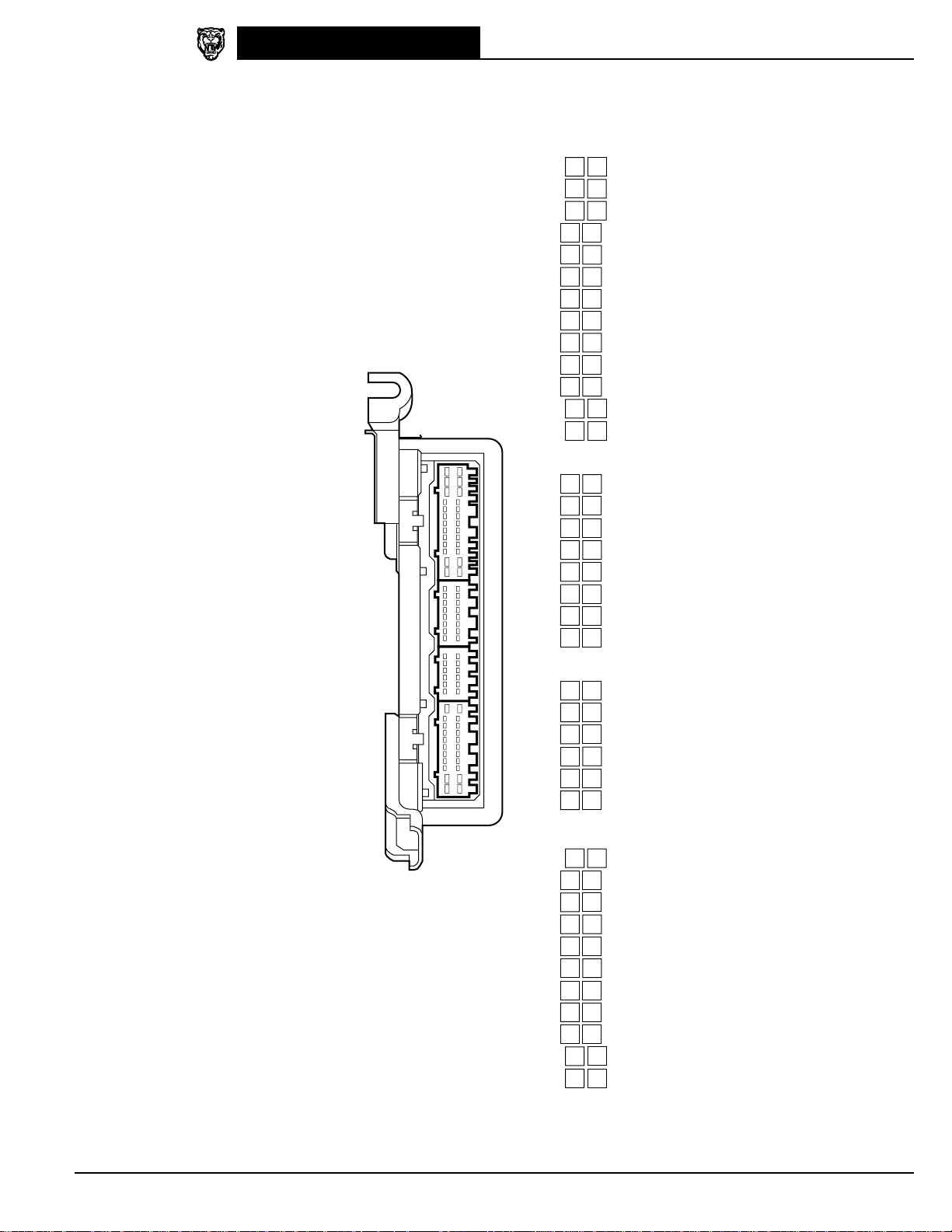
XK8 Range 2000
12
WR
13
B
14
B
15
—
16
—
17
U
18
GW
19
BW
20
BK
21
O
22
—
1
—
2
—
3
—
4
WU
5
—
6
—
7
U
8
U
9
UY
10
W
11
—
7
Y
8
YR
9
—
10
—
11
U
12
WU
1
UY
2
Y
3
YG
4
—
5
OY
6
U
14
—
15
—
16
GR
17
RW
18
GU
19
RU
20
YR
21
Y
22
NR
23
—
24
—
25
O
26
GU
1
RG
2
U
3
UY
4
UY
5
GR
6
RW
7
UY
8
RW
9
—
10
O
11
YG
12
—
13
UY
14
—
15
U
16
GU
1
OG
2
RG
3
Y
4
—
5
YB
6
—
7
OG
8
GO
9
R
10
—
11
—
12
OY
13
UY
AC4 AC3 AC2 AC1
Control Module Pin Identification
AC1 / 26-WAY / GREY
DATE OF ISSUE: September 1999
AC2 / 16-WAY / GREY
AIR CONDITIONING CONTROL MODULE
AC4 / 22-WAY / GREY AC3 / 12-WAY / GREY
27
Page 30

Control Module Pin Identification
1
WG
2
RG
3
YR
4
BK
5
—
6
RU
7
YB
8
UY
9
R
10
Y
11
Y
12
—
13
Y
14
U
15
R
16
B
17
RW
18
Y
19
O
20
—
21
—
22
—
23
G
24
G
25
BR
26
—
13
BW
12
RU
11
R
10
O
9
RU
8
RG
7
OG
6
U
5
OY
4
YG
3
RW
2
OY
1
R
26
—
25
—
24
—
23
OG
22
Y
21
RG
20
OY
19
G
18
OG
17
OY
16
Y
15
OY
14
RW
FC25 FC26
XK8 Range 2000
MAJOR INSTRUMENT PACK
FC26 / 26-WAY / YELLOW
28
FC25 / 26-WAY / BLACK
DATE OF ISSUE: September 1999
Page 31

FC14
79
NG
80
N
81
GR
82
GR
83
GB
84
U
85
Y
86
OG
87
Y
88
YG
89
GR
90
BG
91
BW
53
R
54
G
55
YU
56
OY
57
—
58
YB
59
Y
60
RW
61
WG
62
GU
63
Y
64
—
65
—
27
GO
28
RW
29
Y
30
U
31
Y
32
WR
33
RG
34
GO
35
G
36
GW
37
GR
38
O
39
Y
1
RW
2
GW
3
W
4
GU
5
YR
6
Y
7
RU
8
—
9
GU
10
YR
11
YB
12
W
13
GO
92
YB
93
Y
94
G
95
RU
96
N
97
WG
98
GB
99
UY
100
BR
101
RW
102
N
103
—
104
NW
66
RU
67
O
68
OG
69
O
70
GW
71
YR
72
—
73
GO
74
RW
75
—
76
GO
77
GU
78
U
40
WU
41
RW
42
UY
43
BG
44
OY
45
U
46
—
47
—
48
OG
49
—
50
GW
51
RW
52
BW
14
U
15
WU
16
RW
17
OY
18
YB
19
WG
20
OG
21
—
22
WB
23
WU
24
NW
25
B
26
YG
13
—
12
—
11
—
10
BK
9
—
8
GW
7
YU
6
—
5
RW
4
—
3
GW*
2
—
1
R
26
YR
25
—
24
—
23
—
22
—
21
—
20
—
19
YR
18
—
17
—
16
—
15
—
14
—
8
Y
7
OG
6
NR
5
Y
4
GW*
3
U*
2
O
1
O
16
U
15
NW
14
BK
13
BK
12
—
11
—
10
UY*
9
GR*
BT41 BT40
10
—
9
YB
8
OG
7
O
6
O
5
—
4
NR
3
—
2
—
1
YB
20
—
19
—
18
—
17
Y
16
O
15
—
14
WU
13
WR
12
BK
11
—
FC22
1
—
2
—
3
—
4
—
5
—
6
—
7
—
8
—
9
—
10
—
11
—
12
—
13
—
14
O
15
UY
16
RW
17
R
18
RU
19
U
20
OY
21
RU
22
RG
23
RW
24
WG
25
R
26
BK
BT18
XK8 Range 2000
LAMP CONTROL MODULE
BT18 / 26-WAY / YELLOW
Control Module Pin Identification
KEY TRANSPONDER MODULE
FC22 / 20-WAY / GREEN
BODY PROCESSOR MODULE
DATE OF ISSUE: September 1999
FC14 / 104-WAY / GREY
* Not used – COUPE Vehicless.
SECURITY AND LOCKING CONTROL MODULE
BT41 / 26-WAY / BLACK BT40 / 16-WAY / BLACK
29
Page 32

Control Module Pin Identification
DD11 DD10
7
BR
6
WU
5
GU
4
NG
3
YR
2
U
1
NR
15
WG
14
—
13
—
12
OY
11
—
10
WB
9
Y
8
BK
22
UY
21
O
20
GW
19
—
18
—
17
O
16
—
7
O
6
YB
5
Y
4
UY
3
U
2
BW
1
N
15
OY
14
GW
13
UY
12
RW
11
U
10
BG
9
U
8
BK
22
OG
21
RU
20
WU
19
GB
18
BO
17
B
16
Y
DP11 DP10
7
—
6
—
5
GU
4
—
3
—
2
—
1
—
15
—
14
—
13
—
12
—
11
—
10
—
9
—
8
—
22
—
21
—
20
GW
19
—
18
—
17
—
16
—
7
O
6
YB
5
Y
4
UY
3
U
2
BW
1
N
15
OY
14
GW
13
UY
12
RW
11
U
10
BG
9
U
8
BK
22
OG
21
RU
20
WU
19
—
18
BO
17
B
16
Y
XK8 Range 2000
DD10 / 22-WAY / BLUE
DRIVER DOOR CONTROL MODULE
DD11 / 22-WAY / BLACK
DP10 / 22-WAY / BLUE
PASSENGER DOOR CONTROL MODULE
DP11 / 22-WAY / BLACK
30
DATE OF ISSUE: September 1999
Page 33

XK8 Range 2000
FC29 FC30
7
WG
8
OY
9
OG
10
—
11
YU
12
OG
1
—
2
—
3
—
4
BK
5
Y
6
R
12
BK
11
RU
10
WU
9
WG
8
RW
7
RW
6
W
5
RG
4
WU
3
WR
2
RU
1
—
14
WU
15
—
16
—
17
—
18
WB
19
—
20
—
21
—
22
—
23
—
24
—
25
—
26
—
1
WG
2
WU
3
—
4
—
5
W
6
G
7
—
8
—
9
—
10
WR
11
YG
12
UY
13
—
9
UY
10
OY
11
W
12
WG
13
GR
14
GU
15
GW
16
BW
1
UY
2
BG
3
O
4
—
5
YU
6
O
7
WU
8
WR
6
—
7
—
8
G
9
Y
10
U
1
BO
2
B
3
OG
4
UY
5
NR
SD3 SD4 SD5
9
UY
10
OY
11
W
12
WG
13
GR
14
GU
15
GW
16
BW
1
UY
2
BG
3
O
4
—
5
YU
6
O
7
WU
8
WR
6
—
7
—
8
G
9
Y
10
U
1
BO
2
B
3
OG
4
UY
5
NR
SP3 SP5
SD5 / 10-WAY / BLACK
AIRBAG / SRS CONTROL MODULE
Control Module Pin Identification
FC29 / 12-WAY / BLACK FC30 / 12-WAY / GREY
DRIVER SEAT CONTROL MODULE
DATE OF ISSUE: September 1999
SD4 / 26-WAY / BLACK
SD3 / 16-WAY / BLACK
PASSENGER SEAT CONTROL MODULE
SP3 / 16-WAY / BLACK SP5 / 10-WAY / BLACK
31
Page 34

Fig. 01.1
COMPONENTS
Component Connector / Type / Color Location / Access
VVT SOLENOID VALVE: VARIABLE VALVE TIMING SOLENOID VALVE – B PI32 / 2-WAY AMP JUNIOR POWER TIMER / BLACK
BATTERY BT66 / EYELET TRUNK, RIGHT HAND SIDE
BODY PROCESSOR MODULE FC14 / 104-WAY AMP EEEC / GREY PASSENGER SIDE FASCIA / AIRBAG BRACKET
FUSE BOX – DRIVER SIDE FC5 / 10-WAY U.T.A. FUSEBOX / NATURAL FASCIA / DRIVER SIDE
FUSE BOX – ENGINE COMPARTMENT LF5 / 10-WAY U.T.A. FUSEBOX / NATURAL ENGINE COMPARTMENT / LEFT FRONT
FUSE BOX – ENGINE MANAGEMENT EM19 / 10-WAY U.T.A. FUSEBOX / NATURAL ENGINE COMPARTMENT / CONTROL MODULE ENCLOSURE
FUSE BOX – PASSENGER SIDE FC20 / 10-WAY U.T.A. FUSEBOX / NATURAL FASCIA / PASSENGER SIDE
FUSE BOX – TRUNK BT10 / 10-WAY U.T.A. FUSEBOX / NATURAL TRUNK / ELECTRICAL CARRIER
HIGH POWER PROTECTION MODULE BT60 / EYELET TRUNK / ADJACENT TO BATTERY
TRANSIT ISOLATION DEVICE BT44 / 2-WAY ECONOSEAL III HC / BLACK TRUNK / ADJACENT TO BATTERY
BT67 / EYELET
FC6 / 10-WAY U.T.A. FUSEBOX / BLACK
FC90 / EYELET
FC92 / EYELET
LF6 / 10-WAY U.T.A. FUSEBOX / BLACK
LF7 / 10-WAY U.T.A. FUSEBOX / GREEN
LF8 / 10-WAY U.T.A. FUSEBOX / BLUE
LF70 / EYELET
EM20 / 10-WAY U.T.A. FUSEBOX / BLACK
EM70 / EYELET
FC21 / 10-WAY U.T.A. FUSEBOX / BLACK
FC90 / EYELET
FC93 / EYELET
BT11 / 10-WAY U.T.A. FUSEBOX / BLACK
BT12 / 10-WAY U.T.A. FUSEBOX / GREEN
BT13 / 10-WAY U.T.A. FUSEBOX / BLUE
BT64 / EYELET
BT61 / EYELET
BT62 / EYELET
BT63 / EYELET
BT49 / 1-WAY LUCAR
BT65 / EYELET
BT66 / EYELET
RELAYS
Relay Color / Stripe Connector / Color Location / Access
AUXILIARY POSITIVE RELAY BROWN BUS PASSENGER SIDE FUSE BOX
EMS CONTROL RELAY BROWN BUS ENGINE MANAGEMENT FUSE BOX
IGNITION POSITIVE RELAY BROWN BUS DRIVER SIDE FUSE BOX
IGNITION POSITIVE RELAY BROWN BUS ENGINE COMPARTMENT FUSE BOX
IGNITION POSITIVE RELAY BROWN BUS TRUNK FUSE BOX
HARNESS-TO-HARNESS CONNECTORS
Connector Type / Color Location / Access
BT2 20-WAY MULTILOCK 070 / WHITE TRUNK / ABOVE RIGHT HAND REAR WHEEL ARCH
BT79 EYELET TRANSMISSION TUNNEL
BT80 EYELET ENGINE COMPARTMENT / FALSE BULKHEAD, RIGHT HAND SIDE
EM71 EYELET TRANSMISSION TUNNEL
FC91 EYELET TRANSMISSION TUNNEL
LF71 EYELET TRANSMISSION TUNNEL
RH2 20-WAY MULTILOCK 070 / WHITE REAR OF CENTER CONSOLE ASSEMBLY
ST1 EYELET ENGINE COMPARTMENT / FALSE BULKHEAD, RIGHT HAND SIDE
GROUNDS
Ground Location / Type
BT68 BATTERY GROUND STUD
BT2BR EYELET (PAIR) – RIGHT HAND LEG / TRUNK, RIGHT REAR
BT2BS EYELET (SINGLE) / TRUNK, RIGHT REAR
Refer to the front of this book for detailed information and illustrations regarding the location and identification of harnesses, relays, grounds, control modules
and control module pins.
DATE OF ISSUE: September 1999
Page 35

XK8 Range 2000
Main Power Distribution
Main Power Distribution Fig. 01.1
B
BT68
DRIVER DOOR CONTROL MODULE:
WINDOW LIFT OPERATION
PASSENGER DOOR CONTROL MODULE:
(CIRCUIT CONTINUED)
WINDOW LIFT OPERATION
(CIRCUIT CONTINUED)
R
BT67 BT66
BATTERY HIGH POWER
15.1
26
15.1
49
BATTERY POST
BT60 BT63
PROTECTION MODULE
NR
BT44-2
NW
BT44-1
(BT65)
WG WG
BT2-14
BT49
ISOLATION DEVICE
WG
WU
WR
FC14-97
FC14-15
FC14-32
RH2-20
5
II
17
I
250A x 2
250A
TRANSIT
O
I
I
25 A
LOGIC
POWER
BT61
BT62
B+
(BT66)
TUNNEL
R
R
R
STUD CONNECTOR
BT79
FC91
EM71
LF71
R
R
R
FALSE BULKHEAD
STUD CONNECTOR
BT80
ST1
R
03.1
6
03.2
STARTER
R
(RHD)
(LHD)
ECM CONTROL
04.4
(CIRCUIT CONTINUED)
12
II
RG
BT12-9
2
5
IGNITION POSITIVE
1
II
13
I
R
BT64 FC90
1
3
RELAY
1
09.2
1
07.2
2
09.2
3
04.3
4
5
6
04.6
09.2
19.1 19.1
RELAYS
WR R
FC21-6
2
1
3
5
AUXILIARY POSITIVE
RELAY
2
2
I
R
FC93
11
II
RG
FC6-6
2
1
3
5
IGNITION POSITIVE
RELAY
3
3 4
II
R
R
FC92 FC90
10
II
RG
LF7-9
2
5
IGNITION POSITIVE
4
II
RELAY
1
2
3
4
5
6
RELAYS
07.2
09.1
09.1
14.1
09.1
13.2
U
R
EM20-6
LF70
2
5
E
1
5
EMS CONTROL
RELAY
5
3
1
3
13.3
EM70
04.1
04.2
R
16
Fig. 01.1 Fig. 01.1 Fig. 01.2
15
II E
752
BODY PROCESSOR
MODULE
53 92
Fig. 01.3
652
II II
Fig. 01.4
IGNITION AUXILIARY POWER BUS
BATTERY POWER BUS
IGNITION POWER BUS
TRUNK FUSE BOX PASSENGER SIDE
53 67
EE
Fig. 01.5
19
1
I
BATTERY POWER BUS
FUSE BOX
Fig. 02.1
I
O
Input
Output
BATTERY POWER BUS
IGNITION POWER BUS
DRIVER SIDE
FUSE BOX
Signal Ground (SG)
D
Serial and Encoded Communications
IGNITION POWER BUS
ENGINE COMPARTMENT
C
CAN (Network)
S
SCP Network
BATTERY POWER BUS
FUSE BOX
ENGINE MANAGEMENT POWER BUS
VARIANT:
VIN RANGE:
DATE OF ISSUE:
BATTERY POWER BUS
ENGINE MANAGEMENT
FUSE BOX
All Vehicles
A00116
➞
September 1999
Page 36

Fig. 01.2
COMPONENTS
Component Connector / Type / Color Location / Access
FUSE BOX – DRIVER SIDE FC5 / 10-WAY U.T.A. FUSEBOX / NATURAL FASCIA / DRIVER SIDE
FUSE BOX – PASSENGER SIDE FC20 / 10-WAY U.T.A. FUSEBOX / NATURAL FASCIA / PASSENGER SIDE
HARNESS-TO-HARNESS CONNECTORS
Connector Type / Color Location / Access
AC12 20-WAY MULTILOCK 070 / WHITE FASCIA TOP CONNECTOR MOUNTING BRACKET / RIGHT HAND SIDE
AC13 20-WAY MULTILOCK 070 / YELLOW FASCIA BOTTOM CONNECTOR MOUNTING BRACKET / RIGHT HAND SIDE
AC14 14-WAY MULTILOCK 070 / GREY FASCIA BOTTOM CONNECTOR MOUNTING BRACKET / RIGHT HAND SIDE
AC15 20-WAY MULTILOCK 070 / GREY FASCIA BOTTOM CONNECTOR MOUNTING BRACKET / RIGHT HAND SIDE
AC16 6-WAY MULTILOCK 070 / YELLOW LEFT HAND ‘A’ POST CONNECTOR MOUNTING BRACKET / ‘A’ POST TRIM
BT2 20-WAY MULTILOCK 070 / WHITE TRUNK / ABOVE RIGHT HAND REAR WHEEL ARCH
BT58 4-WAY ECONOSEAL III HC / BLACK TRUNK / ABOVE RIGHT HAND REAR WHEEL ARCH
DD1 23-WAY AMP – FORD / BLACK DRIVER SIDE ‘A’ POST MOUNTING BRACKET/ ‘A’ POST TRIM
DP1 23-W AY AMP – FORD / BLACK PASSENGER SIDE ‘A’ POST / ‘A’ POST TRIM
IC2 14-WAY MULTILOCK 070 / WHITE BELOW CENTER CONSOLE GLOVE BOX
LF1 20-WAY MULTILOCK 070 / GREY LEFT HAND ‘A’ POST CONNECTOR MOUNTING BRACKET / ‘A’ POST TRIM
RF1 18-WAY MULTILOCK 070 / YELLOW RIGHT HAND ‘A’ POST CONNECTOR MOUNTING BRACKET / ‘A’ POST TRIM
RH14 2-WAY ECONOSEAL III HC / BLACK REAR OF CENTER CONSOLE ASSEMBLY
RH2 20-WAY MULTILOCK 070 / WHITE REAR OF CENTER CONSOLE ASSEMBLY
SD1 8-WAY MULTILOCK 070 / YELLOW BELOW DRIVER SEAT
SP1 8-WAY MULTILOCK 070 / YELLOW BELOW PASSENGER SEAT
FC6 / 10-WAY U.T.A. FUSEBOX / BLACK
FC90 / EYELET
FC92 / EYELET
FC21 / 10-WAY U.T.A. FUSEBOX / BLACK
FC90 / EYELET
FC93 / EYELET
Refer to the front of this book for detailed information and illustrations regarding the location and identification of harnesses, relays, grounds, control modules
and control module pins.
DATE OF ISSUE: September 1999
Page 37

XK8 Range 2000
Battery Power Distribution: Driver and Passenger Side Fuse Boxes
23
Battery Power Distribution:
Driver and Passenger Side Fuse Boxes
Fig. 01.2
#1 20A
#2 10A
BATTERY POWER BUS
#3 30A
#4 10A
#5 15A
#6 5A
#7 15A
#8 5A
#9
#11 20A
#13 5A
#15 25A
#17 10A
#18 5A
NR
FC6
-1
NW
FC6
-5
NG
FC6
-3
RW
FC6
-8
N
FC5
-9
NR
FC5
-10
NW
FC5
-4
NR
FC5
-7
FC5
-2
FC6
-2
FC6
-4
FC5
-3
FCS5
NR
NW (LHD) NG (RHD)
NW NW
NR
FCS81
NR
NR
SD1-2
LF1-20
FCS19
SD1-5
AC16-3 (LHD)
AC15-2 (RHD)
AC16-1 (LHD)
AC15-20 (RHD)
RH2-8
NG
LFS20
FCS39
N
SDS6
NW (LHD) NG (RHD)
NR
NR NR
NG NG NG
FC5
-1
FC5
-6
NG
R
FCS40
RH14-2
RF1-7
DD1-22
BT2-8
BT58-2
NR
NW
NG
NG
NG
RW
RW
RW
N
NR
NRNR
NR
NW
NR
NG
R
NR
NR
NR
NW
NW
NW
NW
NW
NW
NR
NW
N
N
N
NR
NR
N
NW
NG
NR
NR
11.3
12.3
30
13.1
31
13.1
32
13.1
33
15.1
34
11.1
35
11.2
36
13.1
37
10.1
38
17.1
39
07.1
40
07.1
41
11.1
42
12.3
43
12.3
44
16.1
45
16.1
46
07.2
47
10.1
48
01.1
49
BPM
50
10.2
51
10.2
52
12.4
11.2
12.1
11.3 15.1
13.1
13.2 15.1
13.3
12.4
12.4
16.2
11.2 13.1 13.2 15.1
15.1
13.3
-1
-5
-3
-8
-9
-10
-4
-7
-2
-2
-4
-3
-1
-6
NR
NR
NW
AC13-14
NR
NW
N
N
SP1-5
NOTE: SPS1 – 3-way seat only.
NR
IC2-13
NG (LHD) NW (RHD)
NW
FCS82
NG
NR
NW
ACS3
N
NR
NW
NW
SP1-2
FCS89
NW
DP1-4
NW
DD1-4
FCS23
SPS1
ICS5
AC15-2 (LHD)
AC16-3 (RHD)
AC15-20 (LHD)
AC16-1 (RHD)
RH2-13
FCS88
NW
DPS2
NW
DDS2
NW NW
AC12-20
NG (LHD) NW (RHD)
NW
DP1-22
NW
BT2-2
11.3
07.2
14.1
14.1
14.1
18.1
18.1
18.1
BPM
06.1
13.2
13.2
BPM
11.1
12.1
12.1
07.2
20.1
10.1
01.1
19.1
19.1
08.1
12.1 12.2
09.1 09.2
13.3
13.3
12.2
12.2
11.1
15.1
12.1 12.2 12.3
19.1
11.2 11.3 12.1 13.1 13.2 15.1
12.4
13.3
#1 20A FC21
#2 10A FC21
#3 FC21
BATTERY POWER BUS
#4 5A FC21
#5 5A FC20
#6 10A FC20
#7 20A FC20
#8 5A FC20
#9 10A FC20
#11 20A FC21
#13 FC21
#15 25A FC20
#17 15A FC20
#18 10A FC20
7
8
9
10
11
12
13
14
15
16
17
18
19
20
N
21
N
22
23
24
N
25
26
27
28
29
DRIVER SIDE
FUSE BOX
16
Fig. 01.1 Fig. 01.1 Fig. 01.2
15
II E
752
53 92
Fig. 01.3
652
II II
Fig. 01.4
53 67
EE
Fig. 01.5
PASSENGER SIDE
FUSE BOX
I
19
1
I
Fig. 02.1
O
Input
Output
Signal Ground (SG)
D
Serial and Encoded Communications
C
CAN (Network)
S
SCP Network
VARIANT:
VIN RANGE:
DATE OF ISSUE:
All Vehicles
A00116
September 1999
NOTE: Body Processor Module appears in
BPM
numerous Figures.
➞
Page 38

Fig. 01.3
COMPONENTS
Component Connector / Type / Color Location / Access
FUSE BOX – ENGINE COMPARTMENT LF5 / 10-WAY U.T.A. FUSEBOX / NATURAL ENGINE COMPARTMENT / LEFT FRONT
FUSE BOX – ENGINE MANAGEMENT EM19 / 10-WAY U.T.A. FUSEBOX / NATURAL ENGINE COMPARTMENT / CONTROL MODULE ENCLOSURE
FUSE BOX – TRUNK BT10 / 10-WAY U.T.A. FUSEBOX / NATURAL TRUNK / ELECTRICAL CARRIER
HARNESS-TO-HARNESS CONNECTORS
Connector Type / Color Location / Access
BT1 20-WAY MULTILOCK 070 / WHITE TRUNK / ABOVE RIGHT HAND REAR WHEEL ARCH
IC4 4-WAY MULTILOCK 070 / WHITE TRUNK / LEFT OF ANTENNA ASSEMBLY
RH12 18-WAY MULTILOCK 070 / YELLOW REAR OF CENTER CONSOLE ASSEMBLY
LF6 / 10-WAY U.T.A. FUSEBOX / BLACK
LF7 / 10-WAY U.T.A. FUSEBOX / GREEN
LF8 / 10-WAY U.T.A. FUSEBOX / BLUE
LF70 / EYELET
EM20 / 10-WAY U.T.A. FUSEBOX / BLACK
EM70 / EYELET
BT11 / 10-WAY U.T.A. FUSEBOX / BLACK
BT12 / 10-WAY U.T.A. FUSEBOX / GREEN
BT13 / 10-WAY U.T.A. FUSEBOX / BLUE
BT64 / EYELET
Refer to the front of this book for detailed information and illustrations regarding the location and identification of harnesses, relays, grounds, control modules
and control module pins.
DATE OF ISSUE: September 1999
Page 39

XK8 Range 2000
Battery Power Distribution: Trunk, Engine Compartment and EMS Fuse Boxes
Trunk, Engine Compartment and EMS Fuse Boxes
Battery Power Distribution:
Fig. 01.3
1
RELAYS
Fig. 01.1
#1 5A BT13
BATTERY POWER BUS
#2 20A BT13
#9 10A BT11
#10 15A BT13
#12 20A (CONV.) BT12
#14 40A (CONV.) BT13
#16 5A
#18 30A BT10
#20 20A (CONV.)
#22 20A BT10
(COUPE)
NR
(CONV.)
-7
NW NW
-1
NG
-3
-2
NG
-3
NR
-4
BTS32
BTS4
NR
BT12
-4
NR
BTS44
BT1-3
NR
IC4-10
NOTE: ICS11 – TV and VICS only.
-1
BT10
-3
-2
NG
NR
BTS42
BTS31
BTS36
NR
NR
NG
NG
ICS11
RH12-10
IC4-1
IC4-2
NR
NR
NR
NR
NR
NG
NWNW
NG
NG
NR
NR
NR
NR
NR
NR
NG
NG
NR
NR
NWNW
4 5
RELAYS
09.2
15.2
15.2
15.2
15.2
06.3
16.1
13.1
15.2
15.2
15.2
11.3 15.2
16.2
13.2
13.3
53
54
55
56
57
58
59
60
61
62
63
ENGINE COMPARTMENT
15.2
64
17.2
17.3
17.2
17.3
16.2
16.2
15.2
15.2
04.6
17.3
17.3
65
66
67
68
69
70
71
72
73
Fig. 01.1
#9 10A LF6
#10 LF8
#12 30A
BATTERY POWER BUS
#14 30A LF8
#16 30A LF7
#18 30A LF5
#20 LF5
#22 5A
FUSE BOX
-3
-2
LF7
-3
-4
-4
-1
-3
LF5
-2
NW
NG
NG
NW
NR
NW
13.2
74
04.3
75
04.3
76
06.1
77
06.1
78
04.6
04.6
07.2
07.2
#1 30A
#2 20A
#3 25A EM20
BATTERY POWER BUS
#4 5A (N/A)
#4 10A (SC)
WG
EM20
-1
NW NW
EM20
-5
NW
-3
NR
EM20
-8
(N/A)
EMS41
(SC) NR
NW
#5 10A EM19
06.4
79
ENGINE MANAGEMENT
#6 EM19
#7 EM19
#8 10A EM19
#9 30A EM19
#11 10A EM20
#13
#15 30A EM19
#17 30A EM19
#18 10A EM19
FUSE BOX
-9
-10
-4
-7
-2
-2
EM20
-4
-3
-1
-6
NG
NG
NR
NG
NR
NW
WG
NW
NR
NR
NW
NG
NG
NR
NG
NR
NW
80
81
82
83
84
85
86
87
88
89
90
91
92
04.1 04.2
04.6
03.1
03.2
04.1
04.2
05.1
04.4 04.5
04.3
04.6
04.3
04.6
04.1 04.2
06.4
07.2
07.2
04.3
04.6
04.4 04.5
07.2
04.4
04.5
TRUNK FUSE BOX
16
Fig. 01.1 Fig. 01.1 Fig. 01.2
15
II E
752
53 92
Fig. 01.3
652
II II
Fig. 01.4
53 67
EE
Fig. 01.5
I
19
1
I
Fig. 02.1
O
Input
Output
Signal Ground (SG)
D
Serial and Encoded Communications
C
CAN (Network)
S
SCP Network
VARIANT:
VIN RANGE:
DATE OF ISSUE:
All Vehicles
A00116
➞
September 1999
Page 40

Fig. 01.4
COMPONENTS
Component Connector / Type / Color Location / Access
FUSE BOX – DRIVER SIDE FC5 / 10-WAY U.T.A. FUSEBOX / NATURAL FASCIA / DRIVER SIDE
FUSE BOX – ENGINE COMPARTMENT LF5 / 10-WAY U.T.A. FUSEBOX / NATURAL ENGINE COMPARTMENT / LEFT FRONT
FUSE BOX – PASSENGER SIDE FC20 / 10-WAY U.T.A. FUSEBOX / NATURAL FASCIA / PASSENGER SIDE
FUSE BOX – TRUNK BT10 / 10-WAY U.T.A. FUSEBOX / NATURAL TRUNK / ELECTRICAL CARRIER
HARNESS-TO-HARNESS CONNECTORS
Connector Type / Color Location / Access
AC15 20-WAY MULTILOCK 070 / GREY FASCIA BOTTOM CONNECTOR MOUNTING BRACKET / RIGHT HAND SIDE
BT1 20-WAY MULTILOCK 070 / WHITE TRUNK / ABOVE RIGHT HAND REAR WHEEL ARCH
EM2 20-W AY MULTILOCK 070 / YELLOW ENGINE COMP ARTMENT / ADJACENT TO RIGHT HAND ENCLOSURE
IC2 14-WAY MULTILOCK 070 / WHITE BELOW CENTER CONSOLE GLOVE BOX
IC3 14-WAY MULTILOCK 070 / GREY BELOW CENTER CONSOLE GLOVE BOX
LF3 13-WAY ECONOSEAL III LC / WHITE ENGINE COMPARTMENT / LEFT HAND ENCLOSURE
LF40 13-WAY ECONOSEAL III LC / BLACK ENGINE COMPARTMENT / LEFT HAND ENCLOSURE
LF60 20-WAY MULTILOCK 070 / WHITE LEFT HAND ‘A’ POST CONNECTOR MOUNTING BRACKET / ‘A’ POST TRIM
PI2 13-WAY ECONOSEAL III LC / BLACK ENGINE COMPARTMENT / BRACKET ON TOP OF TRANSMISSION
RF1 18-WAY MULTILOCK 070 / YELLOW RIGHT HAND ‘A’ POST CONNECTOR MOUNTING BRACKET / ‘A’ POST TRIM
RH2 20-WAY MULTILOCK 070 / WHITE REAR OF CENTER CONSOLE ASSEMBLY
FC6 / 10-WAY U.T.A. FUSEBOX / BLACK
FC90 / EYELET
FC92 / EYELET
LF6 / 10-WAY U.T.A. FUSEBOX / BLACK
LF7 / 10-WAY U.T.A. FUSEBOX / GREEN
LF8 / 10-WAY U.T.A. FUSEBOX / BLUE
LF70 / EYELET
FC21 / 10-WAY U.T.A. FUSEBOX / BLACK
FC90 / EYELET
FC93 / EYELET
BT11 / 10-WAY U.T.A. FUSEBOX / BLACK
BT12 / 10-WAY U.T.A. FUSEBOX / GREEN
BT13 / 10-WAY U.T.A. FUSEBOX / BLUE
BT64 / EYELET
Refer to the front of this book for detailed information and illustrations regarding the location and identification of harnesses, relays, grounds, control modules
and control module pins.
DATE OF ISSUE: September 1999
Page 41

XK8 Range 2000
Ignition Switched Power Distribution
Ignition Switched Power Distribution
Fig. 01.4
3
II
#10 5A FC6
IGNITION POWER BUS
#12 10A FC6
#14 10A FC5
#16 5A
DRIVER SIDE
FUSE BOX
2
I
#10 5A FC21
#12 5A FC21
#14 10A FC20
IGNITION AUXILIARY POWER BUS
#16 5A FC20
PASSENGER SIDE
FUSE BOX
-7
-10
-8
FC5
-5
-7
-10
-8
-5
WU
WU
WG
WR
G
W
WU
WU
FCS8
FCS63
FCS99
WU
WU
WU
WU WU
AC15-3
ACS17
WU
WU
WU
WG
FCS29
WG
WG
WR WR
RF1-1
WR
WR WR
EM2-3
EMS15
WR
WR
WR
WR
WR
FC49-1
WR
G
W
IC2-12
WU
WU WU WU
RH12-18 BT1-13
WU
WU
WU
WU
IC3-11
NOTE: ICS10 – TV and VICS only.
ICS10
WU
WU
WUWU
WU
6
II
7
II
8
II
9
II
10
II
11
II
12
II
13
II
14
II
15
II
16
II
17
II
18
II
19
II
20
II
21
II
22
I
23
I
24
I
25
I
26
I
27
I
28
I
29
I
30
I
31
I
20.1
07.2
07.1
07.2
07.2
06.2
04.3
08.1
18.1
11.3
07.2
07.2
05.1
05.1
05.2
14.1
17.1
16.1
19.1
NOT USED
17.2 17.3
17.3
17.3
17.2 17.3
17.3
17.3
17.3
04.6
05.2
05.2
16.2
06.4
1
II
#3 5A BT13
#4 5A BT13
IGNITION POWER BUS
#5 5A BT11
37
II
09.2
1
07.2
2
04.3
4
RELAYS
TRUNK FUSE BOX
4
II
#1 10A LF8
#2 5A LF8
IGNITION POWER BUS
#3 5A LF8
#4 5A LF8
#5 10A LF6
52
II
07.2
1
09.1
2
RELAYS
04.6
WG
-8
-9
BTS1
WR
WW
-2
BT10
-9
-7
-1
-8
WG
WB
LF40-13
WU
LF3-13
WR
LFS5
BT1-8 RH2-4
WB
WU WU
PI2-12
WR
LF60-9
WR
LF3-7
W
EMS6
-9
-2
LF5
-9
WU
W
LF40-10
WR
WG
32
04.6
II
WG
33
09.2
II
WR
34
06.3
II
W
35
18.1
W
FCS44
EMS42
W
WB
WB
WB
WR
WR
WR
WR
WR
WR
WU
W
W
W
II
36
18.1
II
38
17.2
05.1
05.1
03.1
13.2
09.3
09.3
09.3
06.4
06.4
06.1
03.1
04.1
04.3
17.3
05.2
03.2
03.2
04.2
04.6
04.4
04.5
II
39
II
40
II
41
II
42
II
43
II
44
II
45
II
46
II
47
II
48
II
49
II
50
II
51
II
16
Fig. 01.1 Fig. 01.1 Fig. 01.2
15
II E
752
53 92
Fig. 01.3
652
II II
Fig. 01.4
53 67
EE
Fig. 01.5
ENGINE COMPARTMENT
FUSE BOX
I
19
1
I
Fig. 02.1
O
Input
Output
Signal Ground (SG)
D
Serial and Encoded Communications
C
CAN (Network)
S
SCP Network
VARIANT:
VIN RANGE:
DATE OF ISSUE:
All Vehicles
A00116
➞
September 1999
Page 42

Fig. 01.5
COMPONENTS
Component Connector / Type / Color Location / Access
FUSE BOX – ENGINE MANAGEMENT EM19 / 10-WAY U.T.A. FUSEBOX / NATURAL ENGINE COMPARTMENT / CONTROL MODULE ENCLOSURE
HARNESS-TO-HARNESS CONNECTORS
Connector Type / Color Location / Access
BT1 20-WAY MULTILOCK 070 / WHITE TRUNK / ABOVE RIGHT HAND REAR WHEEL ARCH
EM3 14-W AY MULTILOCK 070 / GREY ENGINE COMPARTMENT / ADJACENT TO RIGHT HAND ENCLOSURE
LF3 13-WAY ECONOSEAL III LC / WHITE ENGINE COMPARTMENT / LEFT HAND ENCLOSURE
LF40 13-WAY ECONOSEAL III LC / BLACK ENGINE COMPARTMENT / LEFT HAND ENCLOSURE
PI1 57-WAY SUMITOMO TS090 / BLACK ENGINE COMPARTMENT / BRACKET ON TOP OF TRANSMISSION
RH2 20-WAY MULTILOCK 070 / WHITE REAR OF CENTER CONSOLE ASSEMBLY
EM20 / 10-WAY U.T.A. FUSEBOX / BLACK
EM70 / EYELET
Refer to the front of this book for detailed information and illustrations regarding the location and identification of harnesses, relays, grounds, control modules
and control module pins.
DATE OF ISSUE: September 1999
Page 43

XK8 Range 2000
Engine Management Switched Power Distribution
5
E
WR
WR
#10 10A EM20
-7
WR
EMS7
53
E
54
E
04.1 04.2
04.1 04.2
04.4
04.4
04.5
04.5
Engine Management Switched
Power Distribution
Fig. 01.5
ENGINE MANAGEMENT POWER BUS
#12 10A EM20
#14 10A EM19
#16 5A EM19
-10
-8
-5
WU
WU
W
EMS16
EMS30
WU
LF40-12
(SC)
WU
WU
WU
WU WU
PI1-28
(N/A)
PIS6
WU
WU WU WU WU
EM3-5 RH2-19 BT1-7
WU
LF3-9
WU
WU
WU
WU
WU
WU
WU WU
PI1-47
PIS8
WU
W
55
04.3
E
56
04.4
E
57
04.1 04.2
E
58
04.1 04.2
E
59
04.1
E
60
04.1 04.2
E
61
04.3
E
62
04.1 04.2
E
63
04.3 07.2
E
64
04.1 04.2
E
65
04.4
E
66
04.4
E
67
04.1 04.2
E
04.6
04.5
04.4
04.6
04.6
07.2
04.5
04.4
04.5
04.4
04.5
04.4 04.5
04.4
04.5
16
Fig. 01.1 Fig. 01.1 Fig. 01.2
15
II E
752
53 92
Fig. 01.3
ENGINE MANAGEMENT
652
II II
Fig. 01.4
FUSE BOX
53 67
EE
Fig. 01.5
I
19
1
I
Fig. 02.1
O
Input
Output
Signal Ground (SG)
D
Serial and Encoded Communications
C
CAN (Network)
S
SCP Network
VARIANT:
VIN RANGE:
DATE OF ISSUE:
All Vehicles
A00116
➞
September 1999
Page 44

Fig. 02.1
COMPONENTS
Component Connector / Type / Color Location / Access
IGNITION SWITCH (KEY-IN SWITCH) FC4 / 8-WAY MULTILOCK 070 / WHITE STEERING COLUMN
INERTIA SWITCH FC46 / 3-WAY ECONOSEAL III LC / BLACK ADJACENT TO LEFT HAND FASCIA FUSE BOX
HARNESS-TO-HARNESS CONNECTORS
Connector Type / Color Location / Access
AC13 20-WAY MULTILOCK 070 / YELLOW FASCIA BOTTOM CONNECTOR MOUNTING BRACKET / RIGHT HAND SIDE
BT1 20-WAY MULTILOCK 070 / WHITE TRUNK / ABOVE RIGHT HAND REAR WHEEL ARCH
LF60 20-WAY MULTILOCK 070 / WHITE LEFT HAND ‘A’ POST CONNECTOR MOUNTING BRACKET / ‘A’ POST TRIM
RH2 20-WAY MULTILOCK 070 / WHITE REAR OF CENTER CONSOLE ASSEMBLY
GROUNDS
Ground Location / Type
FC3BL EYELET (PAIR) – LEFT HAND LEG / TRANSMISSION TUNNEL, LEFT HAND SIDE
Refer to the front of this book for detailed information and illustrations regarding the location and identification of harnesses, relays, grounds, control modules
and control module pins.
DATE OF ISSUE: September 1999
Page 45

XK8 Range 2000
Ignition Switched Ground Distribution
Ignition Switched Ground Distribution Fig. 02.1
FC3BL
BK
FCS48
BK
IGNITION SWITCH
FC4-5
IGNITION SWITCH
(OFF)
III
II
I
IGNITION SWITCH
III
FC4-1
II
FC4-3
I
FC4-2
(I)
RW
WU
WR
III
II
I
IGNITION SWITCH
BPM
1
III
II
I
(II)
FCS26
IGNITION SWITCH
WU
WU
(III)
AC13-2
FC46-1
INERTIA SWITCH
III
II
I
WU
FC46-2
FC46-3
GU
RG
FCS25
RG
RG
EM2-11
LF60-8
RH2-9
RG
RG
LFS27
WU
WU
WU
WU
WU
GU
RG
RG
RG
RG
RG
BT1-16
2
II
3
II
4
II
5
II
6
II
7
II
8
II
9
II
10
II
11
II
12
II
14.1
13.2
13.3
20.1
20.2
BPM
04.1
04.2
04.1 04.2
BPM
04.3
04.6
01.1
01.1
01.1
04.4
04.4
07.2
06.1 09.205.3
06.3
16
Fig. 01.1 Fig. 01.1 Fig. 01.2
15
II E
752
53 92
Fig. 01.3
652
II II
Fig. 01.4
FCS20
53 67
EE
Fig. 01.5
WR
13
01.1
I
WR
RH2-10
I
19
1
I
Fig. 02.1
O
Input
Output
Signal Ground (SG)
D
Serial and Encoded Communications
WR
WR
BT1-18
AC13-1
C
CAN (Network)
S
SCP Network
WR
WR
WR
WR
WR
WR
14
19.1
I
15
10.2
I
16
13.2
I
17
I
18
I
19
I
13.3
BPM
07.1
20.1
20.2
NOTE: Body Processor Module appears in
BPM
numerous Figures.
VARIANT:
VIN RANGE:
DATE OF ISSUE:
All Vehicles
A00116
➞
September 1999
Page 46

CONTROL MODULE PIN OUT INFORMATION
BODY PROCESSOR MODULE
P Pin Description Active Inactive
I FC14-7 NEUTRAL SWITCH STATUS GROUND (N) B+ (P , R, D, 4, 3, 2)
D FC14-39 SECURITY ACKNOWLEDGE ENCODED COMMUNICATIONS
I FC14-41 ST ARTER ENGAGE REQUEST GROUND (CRANKING) B+
O FC14-73 STARTER RELAY ACTIVATE GROUND (CRANKING) B+
I FC14-80 BA TTERY SUPPLY VOLTAGE B+ B+
D FC14-92 ENCODED COMMUNICATIONS
ENGINE CONTROL MODULE
P Pin Description Active Inactive
I EM81-12 PARK / NEUTRAL CONFIRMATION B+ (P, N) GROUND (R,D,4,3,2)
I EM82-2 ENGINE CRANK GROUND (CRANKING)
D EM82-15 OK TO START ENCODED COMMUNICATIONS
D EM82-16 SECURITY ACKNOWLEDGE ENCODED COMMUNICATIONS
KEY TRANSPONDER MODULE
P Pin Description Active Inactive
D FC22-9 GLASS BREAKAGE / OK TO START (ENCODED COMMUNICATION)
D FC22-16 OK TO START (ENCODED COMMUNICATION)
D FC22-17 SECURITY ACKNOWLEDGE (ENCODED COMMUNICATION)
Fig. 03.1
COMPONENTS
Component Connector / Type / Color Location / Access
BATTERY BT66 / EYELET TRUNK, RIGHT HAND SIDE
BODY PROCESSOR MODULE FC14 / 104-WAY AMP EEEC / GREY PASSENGER SIDE FASCIA / AIRBAG BRACKET
ENGINE CONTROL MODULE EM80 / 31-WAY AMP 403 / NATURAL ENGINE COMPARTMENT / CONTROL MODULE ENCLOSURE
GENERATOR AN1 / EYELET ENGINE COMPARTMENT / RIGHT FRONT
HIGH POWER PROTECTION MODULE BT60 / EYELET TRUNK / ADJACENT TO BATTERY
IGNITION SWITCH (KEY-IN SWITCH) FC4 / 8-WAY MULTILOCK 070 / WHITE STEERING COLUMN
KEY TRANSPONDER MODULE FC22 / 20-WAY MULTILOCK 040 / GREEN ADJACENT TO DRIVER SIDE FUSE BOX
NEUTRAL SWITCH FC89 / 3-WAY MULTILOCK 070 / GREY GEAR SELECTOR ASSEMBLY
REGULATOR (GENERATOR) PI50 / 3-WAY SUMITOMO 0902 / BLACK ENGINE COMPARTMENT / GENERATOR
STARTER MOTOR ST2 / EYELET ENGINE BLOCK
SUPPRESSION MODULE AN3 / 2-WAY ECONOSEAL III LC/ RED REARWARD OF RIGHT FRONT HEADLAMP
RELAYS
Relay Color / Stripe Connector / Color Location / Access
STARTER RELAY BROWN EM50 / BROWN RH ENCLOSURE RELAYS
HARNESS-TO-HARNESS CONNECTORS
Connector Type / Color Location / Access
BT80 EYELET ENGINE COMPARTMENT / FALSE BULKHEAD, RIGHT HAND SIDE
EM1 20-W AY MULTILOCK 070 / WHITE ENGINE COMPARTMENT / ADJACENT TO RIGHT HAND ENCLOSURE
EM2 20-W AY MULTILOCK 070 / YELLOW ENGINE COMPARTMENT / ADJACENT TO RIGHT HAND ENCLOSURE
EM3 14-W AY MULTILOCK 070 / GREY ENGINE COMPARTMENT / ADJACENT TO RIGHT HAND ENCLOSURE
EM60 2-WAY ECONOSEAL III HC / BLACK ENGINE COMPARTMENT / BEHIND LEFT INNER FENDER HEAT SHIELD
PI1 57-WAY SUMITOMO TS090 / BLACK ENGINE COMPARTMENT / BRACKET ON TOP OF TRANSMISSION
ST1 EYELET ENGINE COMPARTMENT / FALSE BULKHEAD, RIGHT HAND SIDE
BT67 / EYELET
EM81 / 24-WAY AMP 403 / NATURAL
EM82 / 17-WAY AMP 403 / NATURAL
EM83 / 28-WAY AMP 403 / NATURAL
EM84 / 22-WAY AMP 403 / NATURAL
EM85 / 12-WAY MULTILOCK 070 / WHITE
AN2 / EYELET
ST11 / EYELET
BT61 / EYELET
BT62 / EYELET
BT63 / EYELET
ST3 / EYELET
ST10 / EYELET
The following abbreviations are used to represent values for Control Module Pin-Out data
I Input D Serial and Encoded Data B+ Battery Voltage kHz Frequency x 1000
O Output C CAN (Network) V Voltage (DC) ms Milliseconds
SG Signal Ground S SCP Network Hz Frequency mV Millivolts
CAUTION: The information on this data page is furnished to aid the user in understanding circuit operation. THIS INFORMATION SHOULD BE USED FOR REFERENCE
ONLY.
NOTE: The values listed are approximately those that can be expected at the control module connector pins with all circuit connections made and all components
connected and fitted. “Active” means a load is applied or a switch is ON; “Inactive” means a load is not applied or a switch is OFF.
GROUNDS
Ground Location / Type
BT68 BATTERY GROUND STUD
FC3BR EYELET (PAIR) – RIGHT HAND LEG / TRANSMISSION TUNNEL, LEFT HAND SIDE
FOR CONTROL MODULE PIN OUT INFORMATION, UNFOLD PAGE TO LEFT.
Refer to the front of this book for detailed information and illustrations regarding the location and identification of harnesses, relays, grounds, control modules
and control module pins.
DATE OF ISSUE: September 1999
Page 47

BT68
XK8 Range 2000
B
BT67 BT66 BT60 BT63
BATTERY HIGH POWER
R
PROTECTION MODULE
250A x 2
250A
BT61
BT62
Battery; Starter; Generator: AJ27 N/A
FALSE BULKHEAD
R
R
R
01.1
01.1
STUD CONNECTOR
BT80
ST1
Battery; Starter; Generator: AJ27 N/A Fig. 03.1
R
PARK, NEUTRAL
(CIRCUIT CONTINUED)
05.1
BK
FC3BL
BK
FC3BR
BK
FCS48
FC4-5
IGNITION SWITCH
BK
FCS47
FC89-3 FC89-1
(III)
15
III
FC4-1
II
FC4-3
I
FC4-2
RW
WU
WR
1
02.1
02.1
RUBK
N
FC14-80
RW
FC14-41
Y
FC14-39
YB
FC14-92
RU
FC14-7
B+
I
D
D
I
ENGINE
CRANKING
CONTROL
POWER
LOGIC
O
FC14-73
GO
EM1-15
GO
EMS28
82
49
II
GO
W
EM50
3
1
5
WRNW
2
GO
STARTER RELAY
NEUTRAL SWITCH
BODY PROCESSOR
MODULE
EM82-2
EM82-16
GO
YB
FC22-9
Y
EM3-8
Y
FCS74
O
EM2-18
Y
FC22-17
O
FC22-16EM82-15
GLASS BREAKAGE
SECURITY
D
ACKNOWLEDGE
SECURITY
D
ACKNOWLEDGE
OK TO START
ENGINE
START
FUEL PUMP
CONTROL
AND IGNITION
SECURITY
G
EM81-12
ACKNOWLEDGE
I
OK TO START
I
D
D D
16
Fig. 01.1 Fig. 01.1 Fig. 01.2
15
II E
ENGINE CONTROL
MODULE
MAJOR INSTRUMENT PACK: CHARGE INDICATOR
752
(CIRCUIT CONTINUED)
53 92
41
II
08.1
WU
YY
AN3-1
AN3-2
SUPPRESSION
MODULE
Fig. 01.3
652
II II
Fig. 01.4
53 67
EE
KEY TRANSPONDER MODULE
ST3
ST2
WR
R
EM60-2
6
WR
R
B
ST10
PI50-2
Y
PI1-11EM1-14
PI50-1
R
REGULATOR
ST11
AN1
B
STARTER MOTOR
B
AN2
GENERATOR
Fig. 01.5
I
19
1
I
Fig. 02.1
O
Input
Output
Signal Ground (SG)
D
Serial and Encoded Communications
C
CAN (Network)
S
SCP Network
VARIANT:
VIN RANGE:
DATE OF ISSUE:
AJ27 N/A Vehicles
A00116
➞
September 1999
Page 48

CONTROL MODULE PIN OUT INFORMATION
BODY PROCESSOR MODULE
P Pin Description Active Inactive
I FC14-7 NEUTRAL SWITCH STATUS GROUND (N) B+ (P , R, D, 4, 3, 2)
D FC14-39 SECURITY ACKNOWLEDGE ENCODED COMMUNICATIONS
I FC14-41 ST ARTER ENGAGE REQUEST GROUND (CRANKING) B+
O FC14-73 STARTER RELAY ACTIVATE GROUND (CRANKING) B+
I FC14-80 BA TTERY SUPPLY VOLTAGE B+ B+
D FC14-92 ENCODED COMMUNICATIONS
ENGINE CONTROL MODULE
P Pin Description Active Inactive
I EM81-12 PARK / NEUTRAL CONFIRMATION B+ (P, N) GROUND (R,D,4,3,2)
I EM82-2 ENGINE CRANK GROUND (CRANKING)
D EM82-15 OK TO START ENCODED COMMUNICATIONS
D EM82-16 SECURITY ACKNOWLEDGE ENCODED COMMUNICATIONS
KEY TRANSPONDER MODULE
P Pin Description Active Inactive
D FC22-9 GLASS BREAKAGE / OK TO START (ENCODED COMMUNICATION)
D FC22-16 OK TO START (ENCODED COMMUNICATION)
D FC22-17 SECURITY ACKNOWLEDGE (ENCODED COMMUNICATION)
Fig. 03.2
COMPONENTS
Component Connector / Type / Color Location / Access
BATTERY BT66 / EYELET TRUNK, RIGHT HAND SIDE
BODY PROCESSOR MODULE FC14 / 104-WAY AMP EEEC / GREY PASSENGER SIDE FASCIA / AIRBAG BRACKET
DUAL LINEAR SWITCH FC100 / 12-WAYy / MULTILOCK 070 / GREY LEFT HAND SIDE OF GEAR SELECTOR / CENTER CONSOLE
ENGINE CONTROL MODULE EM80 / 31-WAY AMP 403 / NATURAL ENGINE COMPARTMENT / CONTROL MODULE ENCLOSURE
GENERATOR AN1 / EYELET ENGINE COMPARTMENT / RIGHT FRONT
HIGH POWER PROTECTION MODULE BT60 / EYELET TRUNK / ADJACENT TO BATTERY
IGNITION SWITCH (KEY-IN SWITCH) FC4 / 8-WAY MULTILOCK 070 / WHITE STEERING COLUMN
KEY TRANSPONDER MODULE FC22 / 20-WAY MULTILOCK 040 / GREEN ADJACENT TO DRIVER SIDE FUSE BOX
REGULATOR (GENERATOR) PI50 / 3-WAY SUMITOMO 0902 / BLACK ENGINE COMPARTMENT / GENERATOR
STARTER MOTOR ST2 / EYELET ENGINE BLOCK
SUPPRESSION MODULE AN3 / 2-WAY ECONOSEAL III LC/ RED REARWARD OF RIGHT FRONT HEADLAMP
RELAYS
Relay Color / Stripe Connector / Color Location / Access
STARTER RELAY BROWN EM50 / BROWN RH ENCLOSURE RELAYS
HARNESS-TO-HARNESS CONNECTORS
Connector Type / Color Location / Access
BT80 EYELET ENGINE COMPARTMENT / FALSE BULKHEAD, RIGHT HAND SIDE
EM1 20-W AY MULTILOCK 070 / WHITE ENGINE COMPARTMENT / ADJACENT TO RIGHT HAND ENCLOSURE
EM2 20-W AY MULTILOCK 070 / YELLOW ENGINE COMPARTMENT / ADJACENT TO RIGHT HAND ENCLOSURE
EM3 14-W AY MULTILOCK 070 / GREY ENGINE COMPARTMENT / ADJACENT TO RIGHT HAND ENCLOSURE
EM60 2-WAY ECONOSEAL III HC / BLACK ENGINE COMPARTMENT / BEHIND LEFT INNER FENDER HEAT SHIELD
PI1 57-WAY SUMITOMO TS090 / BLACK ENGINE COMPARTMENT / BRACKET ON TOP OF TRANSMISSION
ST1 EYELET ENGINE COMPARTMENT / FALSE BULKHEAD, RIGHT HAND SIDE
BT67 / EYELET
EM81 / 24-WAY AMP 403 / NATURAL
EM82 / 17-WAY AMP 403 / NATURAL
EM83 / 28-WAY AMP 403 / NATURAL
EM84 / 22-WAY AMP 403 / NATURAL
EM85 / 12-WAY MULTILOCK 070 / WHITE
AN2 / EYELET
ST11 / EYELET
BT61 / EYELET
BT62 / EYELET
BT63 / EYELET
ST3 / EYELET
ST10 / EYELET
The following abbreviations are used to represent values for Control Module Pin-Out data
I Input D Serial and Encoded Data B+ Battery Voltage kHz Frequency x 1000
O Output C CAN (Network) V Voltage (DC) ms Milliseconds
SG Signal Ground S SCP Network Hz Frequency mV Millivolts
CAUTION: The information on this data page is furnished to aid the user in understanding circuit operation. THIS INFORMATION SHOULD BE USED FOR REFERENCE
ONLY.
NOTE: The values listed are approximately those that can be expected at the control module connector pins with all circuit connections made and all components
connected and fitted. “Active” means a load is applied or a switch is ON; “Inactive” means a load is not applied or a switch is OFF.
GROUNDS
Ground Location / Type
BT68 BATTERY GROUND STUD
EM1AR EYELET (PAIR) – RIGHT HAND LEG / ENGINE COMPARTMENT, RIGHT HAND ENCLOSURE
EM2AL EYELET (PAIR) – LEFT HAND LEG / ENGINE COMPARTMENT, LEFT HAND ENCLOSURE
FOR CONTROL MODULE PIN OUT INFORMATION, UNFOLD PAGE TO LEFT.
Refer to the front of this book for detailed information and illustrations regarding the location and identification of harnesses, relays, grounds, control modules
and control module pins.
DATE OF ISSUE: September 1999
Page 49

XK8 Range 2000
B
BT67 BT66 BT60 BT63
N
250A x 2
250A
BT61
BT62
Battery; Starter; Generator: AJ27 SC
FALSE BULKHEAD
R
R
R
01.1
01.1
STUD CONNECTOR
BT80
ST1
Battery; Starter; Generator: AJ27 SC Fig. 03.2
R
BT68
EM2AL
(EM1AL)
BATTERY HIGH POWER
PROTECTION MODULE
BK
FCS48
BK
FC3BL
B
EMS43
EM2-2
FC4-5
IGNITION SWITCH
BB
FC100-2
(III)
DUAL LINEAR SWITCH
ENGINE
START
15
III
FC4-1
II
FC4-3
I
FC4-2
RW
WU
WR
1
02.1
02.1
N
FC14-80
RW
FC14-41
Y
FC14-39
YR
FC14-92
B+
I
D
D
ENGINE
CRANKING
CONTROL
O
FC14-73
GO
EM1-15
GO
EMS28
82
49
II
GO
W
EM50
3
1
5
WRNW
2
GO
STARTER RELAY
O
P, N
O
P, N
I
I
RU
FC100-4
G
FC100-11 EM1-11
GO
EM82-2
RU
FC14-7
I
LOGIC
POWER
BODY PROCESSOR
MODULE
FUEL PUMP
CONTROL
AND IGNITION
SECURITY
ACKNOWLEDGE
OK TO START
ENGINE CONTROL
MODULE
MAJOR INSTRUMENT PACK: CHARGE INDICATOR
(CIRCUIT CONTINUED)
I
D
D D
EM81-12
EM82-16
41
II
08.1
G
Y
EM3-8
Y
FCS74
O
EM2-18
WU
YY
PI1-11EM1-14
R
AN3-1
B
AN3-2
SUPPRESSION
MODULE
YB
GLASS BREAKAGE
D
SECURITY
FC22-9
Y
FC22-17
O
FC22-16EM82-15
ACKNOWLEDGE
SECURITY
D
ACKNOWLEDGE
OK TO START
KEY TRANSPONDER MODULE
ST3
ST2
WR
R
EM60-2
6
WR
R
B
ST10
PI50-2
Y
PI50-1
REGULATOR
STARTER MOTOR
B
ST11
AN1
AN2
GENERATOR
16
Fig. 01.1 Fig. 01.1 Fig. 01.2
15
II E
752
53 92
Fig. 01.3
652
II II
Fig. 01.4
53 67
EE
Fig. 01.5
I
19
1
I
Fig. 02.1
O
Input
Output
Signal Ground (SG)
D
Serial and Encoded Communications
C
CAN (Network)
S
SCP Network
VARIANT:
VIN RANGE:
DATE OF ISSUE:
AJ27 SC Vehicles
A00116
➞
September 1999
Page 50

CONTROL MODULE PIN OUT INFORMATION
ENGINE CONTROL MODULE
P Pin Description Active Inactive
O EM80-01 EVAP VALVE ACTIVATE GROUND (VALVE OPEN) B+
O EM80-02 CANISTER CLOSE VALVE ACTIVATE GROUND B+
I EM80-03 GROUND (POWER) GROUND GROUND
O EM80-04 THROTTLE MOTOR POWER SUPPLY B+ GROUND
O EM80-05 THROTTLE MOTOR POWER SUPPLY B+ GROUND
O EM80-06 THROTTLE MOTOR POWER SUPPLY B+ GROUND
O EM80-07 THROTTLE MOTOR POWER SUPPLY B+ GROUND
I EM80-08 THROTTLE MOTOR POWER SUPPLY B+ GROUND
I EM80-09 THROTTLE MOTOR POWER SUPPLY B+ GROUND
I EM80-15 EOT FEEDBACK 2.5 V @ 34 °C; 0.5 V @ 90 °C; (DECREASING VOL TAGE WITH TEMPERATURE INCREASE)
D EM80-17 SERIAL COMMUNICATIONS
D EM80-18 SERIAL COMMUNICATIONS
D EM80-19 ECM PROGRAMMING
I EM80-21 GROUND (THROTTLE MOTOR 1) GROUND GROUND
D EM80-27 ECM PROGRAMMING
I EM80-29 GROUND (LOGIC 2) GROUND GROUND
I EM80-31 GROUND (THROTTLE MOTOR 2) GROUND GROUND
O EM81-01 VARIABLE VALVE TIMING SOLENOID + ‘A’ BANK B+ (12% DUTY CYCLE @ IDLE) (INCREASING WITH ADVANCE) GROUND
O EM81-02 VARIABLE VALVE TIMING SOLENOID – ‘A’ BANK GROUND GROUND
O EM81-03 EMS CONTROLLED RELAY ACTIVATE GROUND B+
O EM81-06 VARIABLE VALVE TIMING SOLENOID + ‘B’ BANK B+ (12% DUTY CYCLE @ IDLE) (INCREASING WITH ADVANCE) GROUND
O EM81-07 VARIABLE VALVE TIMING SOLENOID – ‘B’ BANK GROUND GROUND
I EM81-08 GROUND (POWER) GROUND GROUND
I EM81-09 PEDAL POSITION FEEDBACK (PPS/1) 0.6 V = FOOT OFF; 3.8 V = PEDAL FULLY DEPRESSED
I EM81-10 TPS FEEDBACK (TPS/1) 0.5 V = IDLE; 4.75 V = WOT
I EM81-12 PARK / NEUTRAL CONFIRMATION B+ (P, N) GROUND (R,D,4,3,2)
I EM81-16 FUEL TANK PRESSURE SENSOR FEEDBACK 4.9 V = LOW PRESSURE, 0.2 V = HIGH PRESSURE
I EM81-17 EMS SWITCHED POWER SUPPLY 1 B+ 0 V
I EM81-18 PEDAL POSITION FEEDBACK (PPS/2) 0.8 V = FOOT OFF; 2.4 V = PEDAL FULLY DEPRESSED
I EM81-19 TPS FEEDBACK (TPS/2) 0.6 V = IDLE; 4.85 V = WOT
I EM81-21 GROUND (LOGIC 1) GROUND GROUND
I EM81-22 PARKING BRAKE SWITCH GROUND (APPLIED) B+
SG EM81-24 PEDAL POSITION / THROTTLE POSITION SENSORS SHIELD GROUND GROUND
O EM82-01 SENSOR SUPPLY VOLTAGE 1 5 V 5 V
I EM82-02 ENGINE CRANK GROUND (CRANKING)
I EM82-04 HO2S, UPSTREAM ‘A’ BANK – VARIABLE CURRENT (µA) 3.5 V
I EM82-05 HO2S, UPSTREAM ‘B’ BANK – VARIABLE CURRENT (µA) 3.5 V
O EM82-06 THROTTLE MOTOR POWER RELAY ACTIVATE GROUND B+
SG EM82-07 SENSORS SIGNAL GROUND 1 GROUND GROUND
I EM82-08 BRAKE SWITCH GROUND B+
I EM82-09 IGNITION SWITCHED POWER SUPPLY B+ B+
SG EM82-10 HO2S, UPSTREAM ‘A’ BANK – CONSTANT 3.8 V
SG EM82-11 HO2S, UPSTREAM ‘B’ BANK – CONSTANT 3.8 V
I EM82-12 INERTIA SWITCH ACTIVATED (VEHICLE IMP ACT) GROUND B+
I EM82-13 EMS SWITCHED POWER SUPPLY 2 B+ 0 V
I EM82-14 ECT FEEDBACK 0.41 V @ 90 °C (DECREASING VOLTAGE WITH TEMPERA TURE INCREASE)
D EM82-15 OK TO START ENCODED COMMUNICATIONS
D EM82-16 SECURITY ACKNOWLEDGE ENCODED COMMUNICATIONS
I EM82-17 IATS FEEDBACK 0.98 V @ 10 °C (DECREASING VOLTAGE WITH TEMPERATURE INCREASE)
O EM83-03 AIR ASSIST CLOSE VALVE ACTIVATE 8 V @ IDLE (78% DUTY CYCLE)
O EM83-05 SENSOR SUPPLY VOLTAGE 2 5 V 5 V
SG EM83-06 SENSOR SHIELD GROUND GROUND
SG EM83-07 CKPS SIGNAL GROUND GROUND GROUND
I EM83-08 CKPS SIGNAL 5 V @ 1000 RPM = 45 Hz; 2000 RPM = 90 Hz
SG EM83-09 CMPS, ‘A’ BANK SIGNAL GROUND GROUND GROUND
SG EM83-12 HO2S SHIELD GROUND GROUND
SG EM83-13 SENSORS SIGNAL GROUND 2 GROUND GROUND
I EM83-14 KNOCK SENSOR, ‘A’ BANK FEEDBACK 0 kHz = NO KNOCK, 2 – 20 kHz = KNOCK
C EM83-15 CAN NETWORK 15 – 1500 Hz
C EM83-16 CAN NETWORK 15 – 1500 Hz
SG EM83-17 CMPS, ‘B’ BANK SIGNAL GROUND GROUND GROUND
I EM83-18 CMPS, ‘B’ BANK SIGNAL 0.7 – 1 VAC @ 1000 RPM = 43 Hz; 2000 RPM = 72 Hz
I EM83-19 CMPS, ‘A’ BANK SIGNAL 0.7 – 1 V AC @ 1000 RPM = 43 Hz; 2000 RPM = 72 Hz
I EM83-20 BATTERY POWER SUPPLY B+ B+
I EM83-21 HO2S, ‘A’ BANK DOWNSTREAM 0.1 – 0.9 V @ IDLE (SWING)
I EM83-22 HO2S, ‘B’ BANK DOWNSTREAM 0.1 – 0.9 V @ IDLE (SWING)
I EM83-23 KNOCK SENSOR, ‘B’ BANK FEEDBACK 0 kHz = NO KNOCK, 2 – 20 kHz = KNOCK
C EM83-24 CAN NETWORK 15 – 1500 Hz
C EM83-25 CAN NETWORK 15 – 1500 Hz
O EM83-26 MAFS REFERENCE GROUND GROUND GROUND
O EM83-27 MAFS REFERENCE GROUND GROUND GROUND
I EM83-28 MAFS FEEDBACK 1.2 V @ IDLE, INCREASING WITH RPM INCREASE
I EM84-01 GROUND (DOWNSTREAM HO2S HEATERS) GROUND GROUND
O EM84-07 HO2S HEATER, ‘A ’ BANK DOWNSTREAM CONTROL GROUND (20 – 60% DUTY CYCLE) B+
O EM84-15 HO2S HEATER, ‘B’ BANK DOWNSTREAM CONTROL GROUND (20 – 60% DUTY CYCLE) B+
I EM84-16 GROUND (INJECTORS 1A, 2B, 3B, 4A) GROUND GROUND
O EM84-17 IGNITION MODULE 4B SWITCHING GROUND (85 – 90% DUTY CYCLE @ IDLE) B+
I EM84-22 GROUND (INJECTORS 1B, 2A, 3A, 4B) GROUND GROUND
O EM85-01 HO2S HEATER, ‘A’ BANK UPSTREAM CONTROL GROUND (85 – 90% DUTY CYCLE AT IDLE) B+
O EM85-02 HO2S HEATER, ‘B’ BANK UPSTREAM CONTROL GROUND (85 – 90% DUTY CYCLE AT IDLE) B+
O EM85-05 “COOL BOX” COOLING FAN ACTIV ATE GROUND B+
I EM85-06 GROUND (HO2S A UPSTREAM HEATER) GROUND GROUND
I EM85-07 GROUND (HO2S B UPSTREAM HEATER) GROUND GROUND
I EM85-08 HO2S HEATERS OBD MONITOR HEATERS ACTIVE = B+ V
NOTE: Refer to the Appendix at the rear of this book for CAN and SCP Network Messages.
The following abbreviations are used to represent values for Control Module Pin-Out data
I Input D Serial and Encoded Data B+ Battery Voltage kHz Frequency x 1000
O Output C CAN (Network) V Voltage (DC) ms Milliseconds
SG Signal Ground S SCP Network Hz Frequency mV Millivolts
CAUTION: The information on this data page is furnished to aid the user in understanding circuit operation. THIS INFORMATION SHOULD BE USED FOR REFERENCE
ONLY.
NOTE: The values listed are approximately those that can be expected at the control module connector pins with all circuit connections made and all components
connected and fitted. “Active” means a load is applied or a switch is ON; “Inactive” means a load is not applied or a switch is OFF.
Fig. 04.1
COMPONENTS
Component Connector / Type / Color Location / Access
AIR ASSIST CLOSE VALVE PI29 / 3-WAY SUMITOMO SS / GREY ENGINE COMPARTMENT / THROTTLE ASSEMBLY
BRAKE SWITCH AC24 / 4-WAY MULTILOCK 070 / WHITE TOP OF BRAKE PEDAL
CCV: CANISTER CLOSE VALVE BT14 / 2-WAY YAZAKI 090 / BLACK BEHIND REAR AXLE / RIGHT HAND SIDE
CKPS: CRANKSHAFT POSITION SENSOR PI17 / 3-WAY ECONOSEAL III LC / BLACK ENGINE / REAR OF BED PLATE
CMPS: CAMSHAFT POSITION SENSOR – A BANK PI16 / 2-WAY YAZAKI 090 / BLACK ‘A’ BANK CYLINDER HEAD, REAR
CMPS: CAMSHAFT POSITION SENSOR – B BANK PI15 / 2-WAY YAZAKI 090 / BLACK ‘B’ BANK CYLINDER HEAD, REAR
ECM AND TCM COOLING FAN EM64 / 2-WAY MULTILOCK 070 / WHITE ENGINE COMPARTMENT / CONTROL MODULE ENCLOSURE
ECTS: ENGINE COOLANT TEMPERATURE SENSOR PI4 / 2-WAY ECONOSEAL E J2 / GREY ENGINE COMPARTMENT / REAR OF ENGINE TOP HOSE
ENGINE CONTROL MODULE EM80 / 31-WAY AMP 403 / NATURAL ENGINE COMPARTMENT / CONTROL MODULE ENCLOSURE
EOTS: ENGINE OIL TEMPERATURE SENSOR PI38 / 2-WAY ECONOSEAL EC J2 / GREY ENGINE BLOCK / BELOW GENERATOR
EVAPP: EVAPORATIVE EMISSION CONTROL VALVE LF58 / 2-WAY ECONOSEAL J2 / BLACK BEHIND LEFT HAND WHEEL ARCH LINER
FTPS: FUEL TANK PRESSURE SENSOR FT2 / 3-WAY ECONOSEAL III LC / BLACK TRUNK / FUEL TANK EVAPORATIVE FLANGE
HO2S: HEATED OXYGEN SENSOR – A DOWNSTREAM EM22 / 2-WAY SUMITOMO 090 II / BLACK ‘A’ BANK CATALYTIC CONVERTER
HO2S: HEATED OXYGEN SENSOR – A UPSTREAM EM21 / 4-WAY SUMITOMO 090 II / GREY ‘A’ BANK CATALYTIC CONVERTER
HO2S: HEATED OXYGEN SENSOR – B DOWNSTREAM EM24 / 2-WAY SUMITOMO 090 II / BLACK ‘B’ BANK CATALYTIC CONVERTER
HO2S: HEATED OXYGEN SENSOR – B UPSTREAM EM23 / 4-WAY SUMITOMO 090 II / GREY ‘B’ BANK CATALYTIC CONVERTER
KS: KNOCK SENSOR – A BANK PI26 / 2-WAY ECONOSEAL III LC / BLACK ENGINE VEE / UNDER INTAKE MANIFOLD
KS: KNOCK SENSOR – B BANK PI27 / 2-WAY ECONOSEAL III LC / BLACK ENGINE VEE / UNDER INTAKE MANIFOLD
MAFS: MASS AIR FLOW SENSOR PI35 / 5-WAY YAZAKI 0902 / BLACK ENGINE COMPARTMENT / REARWARD OF AIR CLEANER
PARKING BRAKE SWITCH FC19 / 1-WAY LUCAR POSILOCK / BLACK BELOW PARKING BRAKE LEVER
PPS: PEDAL POSITION SENSORS PI42 / 5-WAY SUMITOMO TS090 / BLACK ENGINE COMPARTMENT / THROTTLE ASSEMBLY
THROTTLE MOTOR PI33 / 2-WAY SUMITOMO HM250 / BLACK ENGINE COMPARTMENT / THROTTLE ASSEMBLY
TPS: THROTTLE POSITION SENSORS PI6 / 4-WAY ECONOSEAL J2T / BLACK ENGINE COMPARTMENT / THROTTLE ASSEMBLY
VVT SOLENOID VALVE: VARIABLE VALVE TIMING SOLENOID VALVE – A PI31 / 2-WAY AMP JUNIOR POWER TIMER / BLACK ENGINE COMPARTMENT / ‘A’ BANK CYLINDER HEAD, FRONT
VVT SOLENOID VALVE: VARIABLE VALVE TIMING SOLENOID VALVE – B PI32 / 2-WAY AMP JUNIOR POWER TIMER / BLACK ENGINE COMPARTMENT / ‘B’ BANK CYLINDER HEAD, FRONT
RELAYS
Relay Color / Stripe Connector / Color Location / Access
THROTTLE MOTOR POWER RELAY BROWN EM16 / BROWN CONTROL MODULE ENCLOSURE RELAYS
O2S HEATERS RELAY BROWN EM61 / BROWN CONTROL MODULE ENCLOSURE RELAYS
HARNESS-TO-HARNESS CONNECTORS
Connector Type / Color Location / Access
AC13 20-WAY MULTILOCK 070 / YELLOW FASCIA BOTTOM CONNECTOR MOUNTING BRACKET / RIGHT HAND SIDE
BT1 20-WAY MULTILOCK 070 / WHITE TRUNK / ABOVE RIGHT HAND REAR WHEEL ARCH
BT2 20-WAY MULTILOCK 070 / WHITE TRUNK / ABOVE RIGHT HAND REAR WHEEL ARCH
EM1 20-W AY MULTILOCK 070 / WHITE ENGINE COMPARTMENT / ADJACENT TO RIGHT HAND ENCLOSURE
EM2 20-W AY MULTILOCK 070 / YELLOW ENGINE COMPARTMENT / ADJACENT TO RIGHT HAND ENCLOSURE
EM3 14-W AY MULTILOCK 070 / GREY ENGINE COMPARTMENT / ADJACENT TO RIGHT HAND ENCLOSURE
FT1 10-WAY MULTILOCK 070 / WHITE FUEL TANK / REAR
LF3 13-WAY ECONOSEAL III LC / WHITE ENGINE COMPARTMENT / LEFT HAND ENCLOSURE
PI1 57-WAY SUMITOMO TS090 / BLACK ENGINE COMPARTMENT / BRACKET ON TOP OF TRANSMISSION
PI2 13-WAY ECONOSEAL III LC / BLACK ENGINE COMPARTMENT / BRACKET ON TOP OF TRANSMISSION
RH1 20-WAY MULTILOCK 070 / GREY BEHIND GLOVE BOX
RH2 20-WAY MULTILOCK 070 / WHITE REAR OF CENTER CONSOLE ASSEMBLY
GROUNDS
Ground Location / Type
EM1AL EYELET (PAIR) – LEFT HAND LEG / ENGINE COMPARTMENT, RIGHT HAND ENCLOSURE
EM1AR EYELET (PAIR) – RIGHT HAND LEG / ENGINE COMPARTMENT, RIGHT HAND ENCLOSURE
EM1BR EYELET (PAIR) – RIGHT HAND LEG / ENGINE COMPARTMENT, RIGHT HAND ENCLOSURE
FOR CONTROL MODULE PIN OUT INFORMATION, UNFOLD PAGE TO LEFT.
Refer to the front of this book for detailed information and illustrations regarding the location and identification of harnesses, relays, grounds, control modules
and control module pins.
EM81 / 24-WAY AMP 403 / NATURAL
EM82 / 17-WAY AMP 403 / NATURAL
EM83 / 28-WAY AMP 403 / NATURAL
EM84 / 22-WAY AMP 403 / NATURAL
EM85 / 12-WAY MULTILOCK 070 / WHITE
DATE OF ISSUE: September 1999
Page 51

XK8 Range 2000
AJ27 N/A NAS Engine Management: Part 1
AJ27 N/A NAS Engine Management: Part 1 Fig. 04.1
ECM AND TCM
COOLING FAN
W
67
E
EM64-2 EM64-1
53
E
54
E
50
II
83
BRAKE SWITCH
OGWU
6
II
AC24-4 AC24-1 EM1-8
PARKING BRAKE
SWITCH
APPLIED ONLY WHEN THE
INERTIA SWITCH IS ACTIVATED
EMS CONTROL RELAY
(CIRCUIT CONTINUED)
SECURITY ACKNOWLEDGE
(CIRCUIT CONTINUED)
SERIAL COMMUNICATION
SERIAL COMMUNICATION
ECM PROGRAMMING
ECM PROGRAMMING
NG
88
WU
62
E
EMS38
EM1BR
3
1
THROTTLE MOTOR
POWER RELAY
OG
AC13-3
OY
FC19
7
II
01.1
ENGINE CRANK
OK TO START
PARK, NEUTRAL
EM16
EMS37 EMS36
EM1AL EM1AR
03.1
03.1
03.1
05.1
CAN
20.1
CAN
20.1
CAN
20.1
CAN
20.1
20.1
20.1
20.1
20.1
GW
5
2
BBBK
FCS35
EM2-13
EMS20
BK
BK
OG
B
B
B
B
B
B
B
B
B
U
WR
WR
W
NR
OY
GU
U
GO
O
Y
G
G
G
Y
Y
O
W
W
U
GW
GW
GR
EM85-05
EM81-17
EM82-13
EM82-09
EM83-20
OG
EM82-08
EM81-22
EM82-12
EM81-03
EM82-02
EM82-15
EM82-16
EM81-12
EM83-15
EM83-16
EM83-24
EM83-25
EM80-17
EM80-18
EM80-19
EM80-27
EM80-08
EM80-09
EM82-06
EM80-29
EM81-21
EM80-03
EM80-21
EM80-31
EM85-07
EM81-08
EM84-01
EM84-16
EM84-22
EM85-06
(CONTINUED Fig. 04.3)
O
B+
B+
B+
B+
O
O
O
O
O
O
I
O
O
O
O
I
I
I
I
I
O
I
I
–
I
–
I
+
O
O
+
I
I
I
I
I
I
I
O
O
I
O
O
O
O
I
MODULE
EM80-01
EM80-02
EM80-04
EM80-05
EM80-06
EM80-07
EM80-15
EM81-01
EM81-02
EM81-06
EM81-07
EM81-09
EM81-10
EM81-16
EM81-18
EM81-19
EM81-24
EM82-01
EM82-04
EM82-05
EM82-07
EM82-10
EM82-11
EM82-14
EM82-17
EM83-03
EM83-05
EM83-06
EM83-07
EM83-08
EM83-09
EM83-12
EM83-13
EM83-14
EM83-17
EM83-18
EM83-19
EM83-21
EM83-22
EM83-23
EM83-26
EM83-27
EM83-28
EM84-07
EM84-15
EM85-01
EM85-02
EM85-08
I
I
I
O
I
D
D
I
C
C
C
C
D
D
D
D
B+
B+
O
I
I
I
I
I
I
I
I
I
I
I
ENGINE CONTROL
UY
O
G
G
R
R
YG
OY
RW
OG
RG
K
U
RG
R
G
BG
OY
R
G
BG
Y
W
UY
O
RU
OY
BG
P
Y
N
BR
BG
S
O
B
G
U
N
N
BW
BW
GW
U
UY
RU
UY
WG
LF58 -1-2
LF3-8
EMS19
EVAPP
UY
EMS18
WU
60
E
VVT
SOLENOID VALVES
A B
PI31 -1 -2 PI32 -1 -2
RW
PI2
OY
-8
PI1
OG
PI1
PI2
-16
-27
-10
CKPS CMPS CMPS KS KS ECTS EOTS MAFS
AB
υ
PI26 -1 -2 PI27 -1 -2 EM21 EM23-3 -4 -2-1 -3 -4 -2-1
BRD
BRD
S
O
S
O
BRD
BRD
EMS2
N
N
BRD
BRD
BG
BG
UY
UY
EMS1
PI1-6
PI38 -1 -2
BG
BG
υ
YG
-9 PI2
YG
PIS1
RG
AB
BRD
-1 PI2 -3 -2
BRD
PI15 -2 -1
B
N
-25 PI1 -26 -24-22 PI1 -23 -21 -17 PI1 -18 -19 PI1 -20 -5 PI1
B
N
EMS9
PI16 -1 -2
Y
BRD
Y
BRD
G
P
G
P
OYBGRG
EM1 -10 -4 -9
RG
OY
RH1 -8 -10 -9
RG
OO O
BT1-6RH2-18EM3-7
59
E
WU
O
OY
BT2 -3 -5 -4
OYBGRG
FT1 -3 -1 -2
RG
OY
FT2 -3 -2BT14 -1 -2
CCV FTPS
PI35 -2 -3 -1PI17 -2 -1 PI4 -2 -1 -4-5
BWGWWUBGO
PIS10
BG
BW
BW
PI1 -54 -56 -52 -57-31
BW
GW
BW
BG
BG
PI2-11
BK
BG
-1
EMS38
BK
EM1BR
57
G
OY
BG
BG
R
E
IATS
υ
BG
O
PI29
-3
CLOSE VALVE
UPSTREAM HO2S DOWNSTREAM HO2S
BA
UU
G
PI33
BRD
G
-2
W
UY
EMS46
PI1 -50 -49 -51
K
PI42
-4
R
BRD
PI2-13
RU
BK
PI29-1PI29
AIR ASSIST
RU
WG
Y
58
E
PI2-7 PI2-6
WU
-2
R
PI33
-1
THROTTLE
MOTOR
A
λ
EM22 EM24-4 -3 -2-1 -4 -3 -2-1
WG
U
U
WG
BRD
EMS8
EM61
5
WG
2
B
EMS36
EMS3
R
BRD
PI42-2 PI42-1 PI42
PPS/1
B
EM1AR
OY
PPS/2
BRD
BG
-3
O2S HEATERS
RELAY
PI1 -3 -4 -1
-14
OY
PIS9
OY
PI6 -3-4 -2 -1
TPS/1
B
λ
N
UY
WG
BRD
3
WG
80
1
WU
64
E
G
U
BRD
TPS/2
THROTTLE ASSEMBLY
BG
16
Fig. 01.1 Fig. 01.1 Fig. 01.2
15
II E
752
53 92
Fig. 01.3
652
II II
Fig. 01.4
53 67
EE
Fig. 01.5
I
19
1
I
Fig. 02.1
O
Input
Output
Signal Ground (SG)
D
Serial and Encoded Communications
C
CAN (Network)
S
SCP Network
VARIANT:
VIN RANGE:
DATE OF ISSUE:
AJ27 N/A NAS Vehicles
A00116
➞
September 1999
Page 52

CONTROL MODULE PIN OUT INFORMATION
ENGINE CONTROL MODULE
P Pin Description Active Inactive
O EM80-01 EVAP VALVE ACTIVATE GROUND (VALVE OPEN) B+
I EM80-03 GROUND (POWER) GROUND GROUND
O EM80-04 THROTTLE MOTOR POWER SUPPLY B+ GROUND
O EM80-05 THROTTLE MOTOR POWER SUPPLY B+ GROUND
O EM80-06 THROTTLE MOTOR POWER SUPPLY B+ GROUND
O EM80-07 THROTTLE MOTOR POWER SUPPLY B+ GROUND
I EM80-08 THROTTLE MOTOR POWER SUPPLY B+ GROUND
I EM80-09 THROTTLE MOTOR POWER SUPPLY B+ GROUND
I EM80-15 EOT FEEDBACK 2.5 V @ 34 °C; 0.5 V @ 90 °C; (DECREASING VOL TAGE WITH TEMPERATURE INCREASE)
D EM80-17 SERIAL COMMUNICATIONS
D EM80-18 SERIAL COMMUNICATIONS
D EM80-19 ECM PROGRAMMING
I EM80-21 GROUND (THROTTLE MOTOR 1) GROUND GROUND
D EM80-27 ECM PROGRAMMING
I EM80-29 GROUND (LOGIC 2) GROUND GROUND
I EM80-31 GROUND (THROTTLE MOTOR 2) GROUND GROUND
O EM81-01 VARIABLE VALVE TIMING SOLENOID + ‘A’ BANK B+ (12% DUTY CYCLE @ IDLE) (INCREASING WITH ADVANCE) GROUND
O EM81-02 VARIABLE VALVE TIMING SOLENOID – ‘A’ BANK GROUND GROUND
O EM81-03 EMS CONTROLLED RELAY ACTIVATE GROUND B+
O EM81-06 VARIABLE VALVE TIMING SOLENOID + ‘B’ BANK B+ (12% DUTY CYCLE @ IDLE) (INCREASING WITH ADVANCE) GROUND
O EM81-07 VARIABLE VALVE TIMING SOLENOID – ‘B’ BANK GROUND GROUND
I EM81-08 GROUND (POWER) GROUND GROUND
I EM81-09 PEDAL POSITION FEEDBACK (PPS/1) 0.6 V = FOOT OFF; 3.8 V = PEDAL FULLY DEPRESSED
I EM81-10 TPS FEEDBACK (TPS/1) 0.5 V = IDLE; 4.75 V = WOT
I EM81-12 PARK / NEUTRAL CONFIRMATION B+ (P, N) GROUND (R,D,4,3,2)
I EM81-17 EMS SWITCHED POWER SUPPLY 1 B+ 0 V
I EM81-18 PEDAL POSITION FEEDBACK (PPS/2) 0.8 V = FOOT OFF; 2.4 V = PEDAL FULLY DEPRESSED
I EM81-19 TPS FEEDBACK (TPS/2) 0.6 V = IDLE; 4.85 V = WOT
I EM81-21 GROUND (LOGIC 1) GROUND GROUND
I EM81-22 PARKING BRAKE SWITCH GROUND (APPLIED) B+
SG EM81-24 PEDAL POSITION / THROTTLE POSITION SENSORS SHIELD GROUND GROUND
O EM82-01 SENSOR SUPPLY VOLTAGE 1 5 V 5 V
I EM82-02 ENGINE CRANK GROUND (CRANKING)
I EM82-04 HO2S, UPSTREAM ‘A’ BANK – VARIABLE CURRENT (µA) 3.5 V
I EM82-05 HO2S, UPSTREAM ‘B’ BANK – VARIABLE CURRENT (µA) 3.5 V
O EM82-06 THROTTLE MOTOR POWER RELAY ACTIVATE GROUND B+
SG EM82-07 SENSORS SIGNAL GROUND 1 GROUND GROUND
I EM82-08 BRAKE SWITCH GROUND B+
I EM82-09 IGNITION SWITCHED POWER SUPPLY B+ B+
SG EM82-10 HO2S, UPSTREAM ‘A’ BANK – CONSTANT 3.8 V
SG EM82-11 HO2S, UPSTREAM ‘B’ BANK – CONSTANT 3.8 V
I EM82-12 INERTIA SWITCH ACTIVATED (VEHICLE IMP ACT) GROUND B+
I EM82-13 EMS SWITCHED POWER SUPPLY 2 B+ 0 V
I EM82-14 ECT FEEDBACK 0.41 V @ 90 °C (DECREASING VOLTAGE WITH TEMPERA TURE INCREASE)
D EM82-15 OK TO START ENCODED COMMUNICATIONS
D EM82-16 SECURITY ACKNOWLEDGE ENCODED COMMUNICATIONS
I EM82-17 IATS FEEDBACK 0.98 V @ 10 °C (DECREASING VOLTAGE WITH TEMPERATURE INCREASE)
O EM83-03 AIR ASSIST CLOSE VALVE ACTIVATE 8 V @ IDLE (78% DUTY CYCLE)
O EM83-05 SENSOR SUPPLY VOLTAGE 2 5 V 5 V
SG EM83-06 SENSOR SHIELD GROUND GROUND
SG EM83-07 CKPS SIGNAL GROUND GROUND GROUND
I EM83-08 CKPS SIGNAL 5 V @ 1000 RPM = 45 Hz; 2000 RPM = 90 Hz
SG EM83-09 CMPS, ‘A’ BANK SIGNAL GROUND GROUND GROUND
SG EM83-12 HO2S SHIELD GROUND GROUND
SG EM83-13 SENSORS SIGNAL GROUND 2 GROUND GROUND
I EM83-14 KNOCK SENSOR, ‘A’ BANK FEEDBACK 0 kHz = NO KNOCK, 2 – 20 kHz = KNOCK
C EM83-15 CAN NETWORK 15 – 1500 Hz
C EM83-16 CAN NETWORK 15 – 1500 Hz
SG EM83-17 CMPS, ‘B’ BANK SIGNAL GROUND GROUND GROUND
I EM83-18 CMPS, ‘B’ BANK SIGNAL 0.7 – 1 VAC @ 1000 RPM = 43 Hz; 2000 RPM = 72 Hz
I EM83-19 CMPS, ‘A’ BANK SIGNAL 0.7 – 1 V AC @ 1000 RPM = 43 Hz; 2000 RPM = 72 Hz
I EM83-20 BATTERY POWER SUPPLY B+ B+
I EM83-21 HO2S, ‘A’ BANK DOWNSTREAM 0.1 – 0.9 V @ IDLE (SWING)
I EM83-22 HO2S, ‘B’ BANK DOWNSTREAM 0.1 – 0.9 V @ IDLE (SWING)
I EM83-23 KNOCK SENSOR, ‘B’ BANK FEEDBACK 0 kHz = NO KNOCK, 2 – 20 kHz = KNOCK
C EM83-24 CAN NETWORK 15 – 1500 Hz
C EM83-25 CAN NETWORK 15 – 1500 Hz
O EM83-26 MAFS REFERENCE GROUND GROUND GROUND
O EM83-27 MAFS REFERENCE GROUND GROUND GROUND
I EM83-28 MAFS FEEDBACK 1.2 V @ IDLE, INCREASING WITH RPM INCREASE
I EM84-01 GROUND (DOWNSTREAM HO2S HEATERS) GROUND GROUND
O EM84-07 HO2S HEATER, ‘A ’ BANK DOWNSTREAM CONTROL GROUND (20 – 60% DUTY CYCLE) B+
O EM84-15 HO2S HEATER, ‘B’ BANK DOWNSTREAM CONTROL GROUND (20 – 60% DUTY CYCLE) B+
I EM84-16 GROUND (INJECTORS 1A, 2B, 3B, 4A) GROUND GROUND
I EM84-22 GROUND (INJECTORS 1B, 2A, 3A, 4B) GROUND GROUND
O EM85-01 HO2S HEATER, ‘A’ BANK UPSTREAM CONTROL GROUND (85 – 90% DUTY CYCLE AT IDLE) B+
O EM85-02 HO2S HEATER, ‘B’ BANK UPSTREAM CONTROL GROUND (85 – 90% DUTY CYCLE AT IDLE) B+
O EM85-05 “COOL BOX” COOLING FAN ACTIV ATE GROUND B+
I EM85-06 GROUND (HO2S A UPSTREAM HEATER) GROUND GROUND
I EM85-07 GROUND (HO2S B UPSTREAM HEATER) GROUND GROUND
I EM85-08 HO2S HEATERS OBD MONITOR HEATERS ACTIVE = B+ V
NOTE: Refer to the Appendix at the rear of this book for CAN and SCP Network Messages.
Fig. 04.2
COMPONENTS
Component Connector / Type / Color Location / Access
AIR ASSIST CLOSE VALVE PI29 / 3-WAY SUMITOMO SS / GREY ENGINE COMPARTMENT / THROTTLE ASSEMBLY
BRAKE SWITCH AC24 / 4-WAY MULTILOCK 070 / WHITE TOP OF BRAKE PEDAL
CKPS: CRANKSHAFT POSITION SENSOR PI17 / 3-WAY ECONOSEAL III LC / BLACK ENGINE / REAR OF BED PLATE
CMPS: CAMSHAFT POSITION SENSOR – A BANK PI16 / 2-WAY YAZAKI 090 / BLACK ‘A’ BANK CYLINDER HEAD, REAR
CMPS: CAMSHAFT POSITION SENSOR – B BANK PI15 / 2-WAY YAZAKI 090 / BLACK ‘B’ BANK CYLINDER HEAD, REAR
ECM AND TCM COOLING FAN EM64 / 2-WAY MULTILOCK 070 / WHITE ENGINE COMPARTMENT / CONTROL MODULE ENCLOSURE
ECTS: ENGINE COOLANT TEMPERATURE SENSOR PI4 / 2-WAY ECONOSEAL E J2 / GREY ENGINE COMPARTMENT / REAR OF ENGINE TOP HOSE
ENGINE CONTROL MODULE EM80 / 31-WAY AMP 403 / NATURAL ENGINE COMPARTMENT / CONTROL MODULE ENCLOSURE
EOTS: ENGINE OIL TEMPERATURE SENSOR PI38 / 2-WAY ECONOSEAL EC J2 / GREY ENGINE BLOACK / BELOW GENERATOR
EVAPP: EVAPORATIVE EMISSION CONTROL VALVE LF58 / 2-WAY ECONOSEAL J2 / BLACK BEHIND LEFT HAND WHEEL ARCH LINER
HO2S: HEATED OXYGEN SENSOR – A DOWNSTREAM EM22 / 2-WAY SUMITOMO 090 II / BLACK ‘A’ BANK CATALYTIC CONVERTER
HO2S: HEATED OXYGEN SENSOR – A UPSTREAM EM21 / 4-WAY SUMITOMO 090 II / GREY ‘A’ BANK CATALYTIC CONVERTER
HO2S: HEATED OXYGEN SENSOR – B DOWNSTREAM EM24 / 2-WAY SUMITOMO 090 II / BLACK ‘B’ BANK CATALYTIC CONVERTER
HO2S: HEATED OXYGEN SENSOR – B UPSTREAM EM23 / 4-WAY SUMITOMO 090 II / GREY ‘B’ BANK CATALYTIC CONVERTER
KS: KNOCK SENSOR – A BANK PI26 / 2-WAY ECONOSEAL III LC / BLACK ENGINE VEE / UNDER INTAKE MANIFOLD
KS: KNOCK SENSOR – B BANK PI27 / 2-WAY ECONOSEAL III LC / BLACK ENGINE VEE / UNDER INTAKE MANIFOLD
MAFS: MASS AIR FLOW SENSOR PI35 / 5-WAY YAZAKI 0902 / BLACK ENGINE COMPARTMENT / REARWARD OF AIR CLEANER
PARKING BRAKE SWITCH FC19 / 1-WAY LUCAR POSILOCK / BLACK BELOW PARKING BRAKE LEVER
PPS: PEDAL POSITION SENSORS PI42 / 5-WAY SUMITOMO TS090 / BLACK ENGINE COMPARTMENT / THROTTLE ASSEMBLY
THROTTLE MOTOR PI33 / 2-WAY SUMITOMO HM250 / BLACK ENGINE COMPARTMENT / THROTTLE ASSEMBLY
TPS: THROTTLE POSITION SENSORS PI6 / 4-WAY ECONOSEAL J2T / BLACK ENGINE COMPARTMENT / THROTTLE ASSEMBLY
VVT SOLENOID VALVE: VARIABLE VALVE TIMING SOLENOID VALVE – A PI31 / 2-WAY AMP JUNIOR POWER TIMER / BLACK ENGINE COMPARTMENT / ‘A’ BANK CYLINDER HEAD, FRONT
VVT SOLENOID VALVE: VARIABLE VALVE TIMING SOLENOID VALVE – B PI32 / 2-WAY AMP JUNIOR POWER TIMER / BLACK ENGINE COMPARTMENT / ‘B’ BANK CYLINDER HEAD, FRONT
RELAYS
Relay Color / Stripe Connector / Color Location / Access
THROTTLE MOTOR POWER RELAY BROWN EM16 / BROWN CONTROL MODULE ENCLOSURE RELAYS
O2S HEATERS RELAY BROWN EM61 / BROWN CONTROL MODULE ENCLOSURE RELAYS
HARNESS-TO-HARNESS CONNECTORS
Connector Type / Color Location / Access
AC13 20-WAY MULTILOCK 070 / YELLOW FASCIA BOTTOM CONNECTOR MOUNTING BRACKET / RIGHT HAND SIDE
EM1 20-W AY MULTILOCK 070 / WHITE ENGINE COMPARTMENT / ADJACENT TO RIGHT HAND ENCLOSURE
EM2 20-W AY MULTILOCK 070 / YELLOW ENGINE COMPARTMENT / ADJACENT TO RIGHT HAND ENCLOSURE
LF3 13-WAY ECONOSEAL III LC / WHITE ENGINE COMPARTMENT / LEFT HAND ENCLOSURE
PI1 57-WAY SUMITOMO TS090 / BLACK ENGINE COMPARTMENT / BRACKET ON TOP OF TRANSMISSION
PI2 13-WAY ECONOSEAL III LC / BLACK ENGINE COMPARTMENT / BRACKET ON TOP OF TRANSMISSION
GROUNDS
Ground Location / Type
EM1AL EYELET (PAIR) – LEFT HAND LEG / ENGINE COMPARTMENT, RIGHT HAND ENCLOSURE
EM1AR EYELET (PAIR) – RIGHT HAND LEG / ENGINE COMPARTMENT, RIGHT HAND ENCLOSURE
EM1BR EYELET (PAIR) – RIGHT HAND LEG / ENGINE COMPARTMENT, RIGHT HAND ENCLOSURE
EM2AL EYELET (PAIR) – LEFT HAND LEG / ENGINE COMPARTMENT, LEFT HAND ENCLOSURE
EM2AR EYELET (PAIR) – RIGHT HAND LEG / ENGINE COMPARTMENT, LEFT HAND ENCLOSURE
EM2BR EYELET (PAIR) – RIGHT HAND LEG / ENGINE COMPARTMENT, LEFT HAND ENCLOSURE
FOR CONTROL MODULE PIN OUT INFORMATION, UNFOLD PAGE TO LEFT.
EM81 / 24-WAY AMP 403 / NATURAL
EM82 / 17-WAY AMP 403 / NATURAL
EM83 / 28-WAY AMP 403 / NATURAL
EM84 / 22-WAY AMP 403 / NATURAL
EM85 / 12-WAY MULTILOCK 070 / WHITE
The following abbreviations are used to represent values for Control Module Pin-Out data
I Input D Serial and Encoded Data B+ Battery Voltage kHz Frequency x 1000
O Output C CAN (Network) V Voltage (DC) ms Milliseconds
SG Signal Ground S SCP Network Hz Frequency mV Millivolts
CAUTION: The information on this data page is furnished to aid the user in understanding circuit operation. THIS INFORMATION SHOULD BE USED FOR REFERENCE
ONLY.
NOTE: The values listed are approximately those that can be expected at the control module connector pins with all circuit connections made and all components
connected and fitted. “Active” means a load is applied or a switch is ON; “Inactive” means a load is not applied or a switch is OFF.
Refer to the front of this book for detailed information and illustrations regarding the location and identification of harnesses, relays, grounds, control modules
and control module pins.
DATE OF ISSUE: September 1999
Page 53

XK8 Range 2000
AJ27 N/A ROW Engine Management: Part 1
AJ27 N/A ROW Engine Management: Part 1 Fig. 04.2
67
E
BRAKE SWITCH
6
II
AC24-4 AC24-1 EM1-8
NOTE: FCS56 – TV vehicles only.
PARKING BRAKE
SWITCH
APPLIED ONLY WHEN THE
INERTIA SWITCH IS ACTIVATED
SECURITY ACKNOWLEDGE
SERIAL COMMUNICATION
SERIAL COMMUNICATION
NG
88
WU
62
E
THROTTLE MOTOR
EMS38
EM1BR
(EM2BR)
ECM AND TCM
COOLING FAN
WU
EM64-2 EM64-1
OG
AC13-3
OY
FCS56
FC19
EMS CONTROL RELAY
(CIRCUIT CONTINUED)
ENGINE CRANK
OK TO START
PARK, NEUTRAL
(CIRCUIT CONTINUED)
CAN
CAN
CAN
CAN
ECM PROGRAMMING
ECM PROGRAMMING
EM16
3
1
5
2
POWER RELAY
EMS37 EMS36
EM1AL
(EM2AL)
BBBK
53
E
54
E
50
II
83
OGWU
OY
7
II
01.1
03.1
03.1
03.1
05.1
20.1
20.1
20.1
20.1
20.1
20.1
20.1
20.1
GW
EM1AR
(EM2AR)
FCS35
EMS20
OG
EM2-13
BK
BK
B
B
B
B
B
B
B
B
B
WR
WR
W
NR
OY
GU
U
GO
O
Y
G
G
G
Y
Y
O
W
W
U
GW
GW
GR
EM85-05
EM81-17
EM82-13
EM82-09
EM83-20
OG
EM82-08
EM81-22
EM82-12
EM81-03
EM82-02
EM82-15
EM82-16
EM81-12
EM83-15
EM83-16
EM83-24
EM83-25
EM80-17
EM80-18
EM80-19
EM80-27
EM80-08
EM80-09
EM82-06
EM80-29
EM81-21
EM80-03
EM80-21
EM80-31
EM85-07
EM81-08
EM84-01
EM84-16
EM84-22
EM85-06
O
B+
B+
B+
B+
I
I
I
O
I
D
D
I
C
–
C
–
C
+
C
+
D
D
D
D
B+
B+
O
I
I
I
I
I
I
I
I
I
I
I
ENGINE CONTROL
MODULE
(CONTINUED Fig. 04.3)
EVAPP
LF58 -1-2
PI31 -1 -2 PI32 -1 -2
UYOYWU
LF3-8
O
EM80-01
O
EM80-04
O
EM80-05
O
EM80-06
O
EM80-07
I
EM80-15
O
EM81-01
O
EM81-02
O
EM81-06
O
EM81-07
I
EM81-09
I
EM81-10
I
EM81-18
I
EM81-19
EM81-24
O
EM82-01
I
EM82-04
I
EM82-05
EM82-07
EM82-10
EM82-11
I
EM82-14
I
EM82-17
O
EM83-03
O
EM83-05
EM83-06
EM83-07
I
EM83-08
EM83-09
EM83-12
EM83-13
I
EM83-14
EM83-17
I
EM83-18
I
EM83-19
I
EM83-21
I
EM83-22
I
EM83-23
O
EM83-26
O
EM83-27
I
EM83-28
O
EM84-07
O
EM84-15
O
EM85-01
O
EM85-02
I
EM85-08
UY
O
G
R
R
YG
OY
RW
OG
RG
K
U
R
G
BG
OY
R
G
BG
Y
W
UY
O
RU
OY
BG
P
Y
N
BR
BG
S
O
B
G
U
N
N
BW
BW
GW
U
UY
RU
UY
WG
EMS19
60
E
EMS18
VVT
SOLENOID VALVES
A B
RW
OG
PI1
PI2
-10
-16
PI2
-8
PI1
CKPS CMPS CMPS KS KS ECTS EOTS MAFS
GW
57
GW
IATS
υ
WUBGO
E
BG
UU
O
AB
BRD
BRD
PI16 -1 -2
P
P
G
G
RG
-27
Y
Y
BRD
-1 PI2 -3 -2
BRD
PI15 -2 -1
B
N
-25 PI1 -26 -24-22 PI1 -23 -21 -17 PI1 -18 -19 PI1 -20 -5 PI1
B
N
EMS9
AB
υ
PI26 -1 -2 PI27 -1 -2 EM21 EM23-3 -4 -2-1 -3 -4 -2-1
BRD
BRD
S
O
S
O
BRD
BRD
N
N
BRD
BRD
UY
UY
PI38 -1 -2
BG
υ
PI35 -2 -3 -1PI17 -2 -1 PI4 -2 -1 -4-5
PIS10
YG
BG
BW
-9 PI2
PI1 -54 -56 -52 -57-31
YG
BW
BW
BW
BW
G
EMS1
OY
BG
EMS2 PIS1
BG
PI1-6
BG
BG
R
PI2-13
PI2-11
PI29
BK
-3
PI29-1PI29
UPSTREAM HO2S DOWNSTREAM HO2S
BA
A
λ
EM22 EM24-4 -3 -2-1 -4 -3 -2-1
G
PI33
BRD
G
-2
W
UY
WG
EMS46
EMS3
PI1 -50 -49 -51
K
BRD
PI42
PI42-2 PI42-1 PI42
-4
EMS8
R
B
OY
U
WG
B
EMS36
EM1AR
(EM2AR)
BG
-3
BRD
BRD
R
RU
BRD
-2
58
Y
E
WU
RU
WG
PI2-7 PI2-6
R
PI33
-1
B
λ
U
WG
N
EM61
RELAY
U
3
1
BRD
5
2
O2S HEATERS
-14
PI1 -3 -4 -1
OY
PIS9
OY
PI6 -3-4 -2 -1
BRD
G
UY
WG
WU
BG
WG
80
64
E
BK
EMS38
BK
EM1BR
(EM2BR)
AIR ASSIST
CLOSE VALVE
THROTTLE
MOTOR
PPS/1
PPS/2
TPS/1
TPS/2
THROTTLE ASSEMBLY
16
Fig. 01.1 Fig. 01.1 Fig. 01.2
15
II E
752
53 92
Fig. 01.3
652
II II
Fig. 01.4
53 67
EE
Fig. 01.5
I
19
1
I
Fig. 02.1
O
Input
Output
Signal Ground (SG)
D
Serial and Encoded Communications
C
CAN (Network)
S
SCP Network
VARIANT:
VIN RANGE:
DATE OF ISSUE:
AJ27 N/A ROW Vehicles
A00116
➞
September 1999
Page 54

CONTROL MODULE PIN OUT INFORMATION
AIR CONDITIONING CONTROL MODULE
P Pin Description Active Inactive
I AC1-1 COMPRESSOR CLUTCH STATUS B+ (ON) 0 V
O AC3-1 AIR CONDITIONING ELECTRICAL LOAD SIGNAL B+ 0 V
I AC4-7 LOAD INHIBIT 0 V B+
O AC4-9 COMPRESSOR CLUTCH ON REQUEST B+ 0 V
I AC4-17 REFRIGERANT 4-WAY PRESSURE SWITCH 0 V (2 – 30 BAR) B+ (OUT OF ACTIVE RANGE)
ENGINE CONTROL MODULE
P Pin Description Active Inactive
I EM80-10 REFRIGERANT 4-WAY PRESSURE SWITCH HIGH PRESSURE GROUND @ 20 BAR (290 PSI)
I EM80-11 A/CCM COMPRESSOR CLUTCH REQUEST B+ GROUND
O EM80-12 ELECTRICAL LOAD INHIBIT GROUND B+
O EM80-16 CRUISE CONTROL ON STATUS LED GROUND B+
D EM80-17 SERIAL COMMUNICATIONS
D EM80-18 SERIAL COMMUNICATIONS
D EM80-19 ECM PROGRAMMING
I EM80-20 CRUISE CONTROL BRAKE CANCEL REQUEST GROUND B+
I EM80-22 REFRIGERANT 4-WAY PRESSURE SWITCH HIGH PRESSURE GROUND @ 12 BAR (174 PSI)
I EM80-23 A/CCM ELECTRICAL LOAD REQUEST (HEATED WINDSHIELD) B+ GROUND
O EM80-25 AIR CONDITIONING COMPRESSOR RELAY ACTIVATE GROUND B+
O EM81-04 PARALLEL (HIGH) SPEED FAN ACTIVATE GROUND B+
O EM81-05 SERIES (LOW) SPEED FAN ACTIVATE GROUND B+
I EM81-13 CRUISE CONTROL ON REQUEST B+ GROUND
I EM81-14 CRUISE CONTROL SET +/- 7.3 V = (+), 8.8 V = (–)B+
I EM81-15 CRUISE CONTROL CANCEL / RESUME 7.3 V = RESUME, 8.8 V = CANCEL B+
I EM83-04 FUEL PUMP RELAY ACTIVATE GROUND B+
I EM83-10 IGNITION MODULES 1A, 2B, 3B, 4A OBD MONITOR 23 Hz @ IDLE (5 V)
I EM83-11 IGNITION MODULES 1B, 2A, 3A, 4B OBD MONITOR 23 Hz @ IDLE (5 V)
O EM84-02 INJECTOR 1A ACTIVATE GROUND B+
O EM84-03 INJECTOR 3B ACTIVATE GROUND B+
O EM84-04 INJECTOR 2B ACTIVATE GROUND B+
O EM84-05 INJECTOR 4A ACTIVATE GROUND B+
O EM84-06 INJECTOR 1B ACTIVATE GROUND B+
O EM84-09 IGNITION MODULE 4A SWITCHING GROUND (85 – 90% DUTY CYCLE @ IDLE) B+
O EM84-10 IGNITION MODULE 3A SWITCHING GROUND (85 – 90% DUTY CYCLE @ IDLE) B+
O EM84-11 IGNITION MODULE 2A SWITCHING GROUND (85 – 90% DUTY CYCLE @ IDLE) B+
O EM84-12 IGNITION MODULE 1A SWITCHING GROUND (85 – 90% DUTY CYCLE @ IDLE) B+
I EM84-13 INJECTOR 4B ACTIVATE GROUND B+
I EM84-14 INJECTOR 3A ACTIVATE GROUND B+
O EM84-17 IGNITION MODULE 4B SWITCHING GROUND (85 – 90% DUTY CYCLE @ IDLE) B+
O EM84-18 IGNITION MODULE 3B SWITCHING GROUND (85 – 90% DUTY CYCLE @ IDLE) B+
O EM84-19 IGNITION MODULE 2B SWITCHING GROUND (85 – 90% DUTY CYCLE @ IDLE) B+
O EM84-20 IGNITION MODULE 1B SWITCHING GROUND (85 – 90% DUTY CYCLE @ IDLE) B+
O EM84-21 INJECTOR 2A ACTIVATE GROUND B+
Fig. 04.3
COMPONENTS
Component Connector / Type / Color Location / Access
AIR CONDITIONING COMPRESSOR CLUTCH PI36 / 1-WAY SUMITOMO 090 A-TYPE / BLACK ENGINE COMPARTMENT / A/C COMPRESSOR
AIR CONDITIONING CONTROL MODULE AC1 / 26-WAY MULTILOCK 47 / GREY A/C UNIT / RIGHT HAND SIDE
BRAKE CANCEL SWITCH AC24 / 4-WAY MULTILOCK 070 / WHITE TOP OF BRAKE PEDAL
SPEED CONTROL ON / OFF SWITCH FC63 / 10-WAY AMP MQL / NATURAL REARWARD OF GEAR SELECTOR
SPEED CONTROL SWITCHES (STEERING WHEEL) SW3 / 3-WAY EPC / BLACK CENTER OF STEERING WHEEL
ENGINE CONTROL MODULE EM80 / 31-WAY AMP 403 / NATURAL ENGINE COMPARTMENT / CONTROL MODULE ENCLOSURE
FUEL INJECTOR – 1A PI7 / 2-WAY AMP JUNIOR POWER TIMER / BLACK INTAKE MANIFOLD / FUEL RAIL
FUEL INJECTOR – 1B PI11 / 2-WAY AMP JUNIOR POWER TIMER / BLACK INTAKE MANIFOLD / FUEL RAIL
FUEL INJECTOR – 2A PI8 / 2-WAY AMP JUNIOR POWER TIMER / BLACK INTAKE MANIFOLD / FUEL RAIL
FUEL INJECTOR – 2B PI12 / 2-WAY AMP JUNIOR POWER TIMER / BLACK INTAKE MANIFOLD / FUEL RAIL
FUEL INJECTOR – 3A PI9 / 2-WAY AMP JUNIOR POWER TIMER / BLACK INTAKE MANIFOLD / FUEL RAIL
FUEL INJECTOR – 3B PI13 / 2-WAY AMP JUNIOR POWER TIMER / BLACK INTAKE MANIFOLD / FUEL RAIL
FUEL INJECTOR – 4A PI10 / 2-WAY AMP JUNIOR POWER TIMER / BLACK INTAKE MANIFOLD / FUEL RAIL
FUEL INJECTOR – 4B PI14 / 2-WAY AMP JUNIOR POWER TIMER / BLACK INTAKE MANIFOLD / FUEL RAIL
FUEL PUMP FT3 / 4-WAY SUMITOMO DL090 / NATURAL TRUNK / TOP OF FUEL TANK
FUSE BOX – TRUNK BT10 / 10-WAY U.T.A. FUSEBOX / NATURAL TRUNK / ELECTRICAL CARRIER
IGNITION COIL – 1A PI51 / 4-WAY YAZAKI / BLACK ENGINE COMPARTMENT / CAMSHAFT COVER
IGNITION COIL – 1B PI55 / 4-WAY YAZAKI / BLACK ENGINE COMPARTMENT / CAMSHAFT COVER
IGNITION COIL – 2A PI52 / 4-WAY YAZAKI / BLACK ENGINE COMPARTMENT / CAMSHAFT COVER
IGNITION COIL – 2B PI56 / 4-WAY YAZAKI / BLACK ENGINE COMPARTMENT / CAMSHAFT COVER
IGNITION COIL – 3A PI53 / 4-WAY YAZAKI / BLACK ENGINE COMPARTMENT / CAMSHAFT COVER
IGNITION COIL – 3B PI57 / 4-WAY YAZAKI / BLACK ENGINE COMPARTMENT / CAMSHAFT COVER
IGNITION COIL – 4A PI54 / 4-WAY YAZAKI / BLACK ENGINE COMPARTMENT / CAMSHAFT COVER
IGNITION COIL – 4B PI58 / 4-WAY YAZAKI / BLACK ENGINE COMPARTMENT / CAMSHAFT COVER
RADIATOR FAN CONTROL RELAY MODULE LF9 / 8-WAY TRW / BLACK ADJACENT TO LEFT HAND HORN
RADIATOR FAN – LH LF13 / 2-WAY REINSHAGEN METRI 630 / BLACK ENGINE COMPARTMENT / FRONT
RADIATOR FAN – RH LF12 / 2-WAY REINSHAGEN METRI 630 / BLACK ENGINE COMPARTMENT / FRONT
REFRIGERANT 4-WAY PRESSURE SWITCH LF57 / 6-WAY ECONOSEAL III LC / BLACK ENGINE COMPARTMENT / REARWARD OF RADIATOR
RELAYS
Relay Color / Stripe Connector / Color Location / Access
AIR CONDITIONING COMPRESSOR CLUTCH RELAY BROWN EM17 LH ENCLOSURE RELAYS
FUEL INJECTION RELAY BROWN EM5 / BROWN CONTROL MODULE ENCLOSURE RELAYS
FUEL PUMP RELAY (#4) BROWN BUS TRUNK FUSE BOX
IGNITION COIL RELAY BROWN EM26 / BROWN CONTROL MODULE ENCLOSURE RELAYS
AC2 / 16-WAY MULTILOCK 47 / GREY
AC3 / 12-WAY MULTILOCK 47 / GREY
AC4 / 22-WAY MULTILOCK 47 / GREY
EM81 / 24-WAY AMP 403 / NATURAL
EM82 / 17-WAY AMP 403 / NATURAL
EM83 / 28-WAY AMP 403 / NATURAL
EM84 / 22-WAY AMP 403 / NATURAL
EM85 / 12-WAY MULTILOCK 070 / WHITE
BT11 / 10-WAY U.T.A. FUSEBOX / BLACK
BT12 / 10-WAY U.T.A. FUSEBOX / GREEN
BT13 / 10-WAY U.T.A. FUSEBOX / BLUE
BT64 / EYELET
The following abbreviations are used to represent values for Control Module Pin-Out data
I Input D Serial and Encoded Data B+ Battery Voltage kHz Frequency x 1000
O Output C CAN (Network) V Voltage (DC) ms Milliseconds
SG Signal Ground S SCP Network Hz Frequency mV Millivolts
CAUTION: The information on this data page is furnished to aid the user in understanding circuit operation. THIS INFORMATION SHOULD BE USED FOR REFERENCE
ONLY.
NOTE: The values listed are approximately those that can be expected at the control module connector pins with all circuit connections made and all components
connected and fitted. “Active” means a load is applied or a switch is ON; “Inactive” means a load is not applied or a switch is OFF.
HARNESS-TO-HARNESS CONNECTORS
Connector Type / Color Location / Access
AC12 20-WAY MULTILOCK 070 / WHITE FASCIA TOP CONNECTOR MOUNTING BRACKET / RIGHT HAND SIDE
AC13 20-WAY MULTILOCK 070 / YELLOW FASCIA BOTTOM CONNECTOR MOUNTING BRACKET / RIGHT HAND SIDE
BT2 20-WAY MULTILOCK 070 / WHITE TRUNK / ABOVE RIGHT HAND REAR WHEEL ARCH
EM1 20-W AY MULTILOCK 070 / WHITE ENGINE COMPARTMENT / ADJACENT TO RIGHT HAND ENCLOSURE
EM2 20-W AY MULTILOCK 070 / YELLOW ENGINE COMPARTMENT / ADJACENT TO RIGHT HAND ENCLOSURE
EM3 14-W AY MULTILOCK 070 / GREY ENGINE COMPARTMENT / ADJACENT TO RIGHT HAND ENCLOSURE
FT1 10-WAY MULTILOCK 070 / WHITE FUEL TANK / REAR
LF3 13-WAY ECONOSEAL III LC / WHITE ENGINE COMPARTMENT / LEFT HAND ENCLOSURE
LF40 13-WAY ECONOSEAL III LC / BLACK ENGINE COMPARTMENT / LEFT HAND ENCLOSURE
PI1 57-WAY SUMITOMO TS090 / BLACK ENGINE COMPARTMENT / BRACKET ON TOP OF TRANSMISSION
PI2 13-WAY ECONOSEAL III LC / BLACK ENGINE COMPARTMENT / BRACKET ON TOP OF TRANSMISSION
RH1 20-WAY MULTILOCK 070 / GREY BEHIND GLOVE BOX
SC3 12-W AY MULTILOCK 070 / GREY RIGHT HAND SIDE OF STEERING COLUMN
SW1 12-WAY MULTILOCK 040 / BLACK INSIDE STEERING COLUMN COWL
SW2 6-WAY JST / WHITE CENTER OF STEERING WHEEL
GROUNDS
Ground Location / Type
BT2AL EYELET (PAIR) – LEFT HAND LEG / TRUNK, RIGHT REAR
EM1AL EYELET (PAIR) – LEFT HAND LEG / ENGINE COMPARTMENT, RIGHT HAND ENCLOSURE
EM1AR EYELET (PAIR) – RIGHT HAND LEG / ENGINE COMPARTMENT, RIGHT HAND ENCLOSURE
EM2AL EYELET (PAIR) – LEFT HAND LEG / ENGINE COMPARTMENT, LEFT HAND ENCLOSURE
EM2AR EYELET (PAIR) – RIGHT HAND LEG / ENGINE COMPARTMENT, LEFT HAND ENCLOSURE
FC3BL EYELET (PAIR) – LEFT HAND LEG / TRANSMISSION TUNNEL, LEFT HAND SIDE
LF2AL EYELET (PAIR) – LEFT HAND LEG / ENGINE COMPARTMENT, FORWARD OF LEFT HAND HOOD CATCH
LF2AR EYELET (PAIR) – RIGHT HAND LEG / ENGINE COMPARTMENT, FORWARD OF LEFT HAND HOOD CATCH
LF2BL EYELET (PAIR) – LEFT HAND LEG / ENGINE COMPARTMENT, FORWARD OF LEFT HAND HOOD CATCH
FOR CONTROL MODULE PIN OUT INFORMATION, UNFOLD PAGE TO LEFT.
Refer to the front of this book for detailed information and illustrations regarding the location and identification of harnesses, relays, grounds, control modules
and control module pins.
DATE OF ISSUE: September 1999
Page 55

XK8 Range 2000
3
1
1
37
II
FUEL PUMP RELAY (#4)
TRUNK FUSE BOX
I
I
O
O
I
I
I
O
O
O
I
I
I
O
I
I
O
O
O
O
O
O
O
O
O
O
O
O
O
O
O
O
ENGINE CONTROL
MODULE
FT3-2
FUEL
PUMP
FT3-1
FUEL TANK
NOTE: ECM power supplies and grounds
shown on Fig. 04.1 and Fig. 04.2.
EM80-10
EM80-11
EM80-12
EM80-16
EM80-20
EM80-22
EM80-23
EM80-25
EM81-04
EM81-05
EM81-13
EM81-14
EM81-15
EM83-04
EM83-10
EM83-11
EM84-02
EM84-03
EM84-04
EM84-05
EM84-06
EM84-09
EM84-10
EM84-11
EM84-12
EM84-13
EM84-14
EM84-17
EM84-18
EM84-19
EM84-20
EM84-21
5
2
FT1-4
FT1-5
#7 20A
NW
B
BT11-1
BT11-10
WU
UY
U
YU
U
Y
UY
RW
WU
W
WU
YR
YG
WR
YG
YG
BG
BO
BW
BW
BW
GW
GO
GR
GU
BR
BG
GU
GO
GW
GB
BO
BT2AL
NW
WR
BT2
RH1
EM2
AJ27 N/A Engine Management: Part 2
RG
-6
RG
EM2-6
UY
EM1-3 AC12-12
U
EM1-13
UY
EM2-12
RU (U*)
EM2-14
* NOTE: Early production vehicles.
U
WRWR
-11
-9
EM5
3
NW
86
1
WB
51
II
FUEL INJECTION
RELAY
WU
Y
LF3-6
LF40-9
LF40-11
5
2
AC12-13
AC13-9
AC12-19
AC12-14
BR
RG
UY
U
UY
U
AC1-01
AC4-09
AC4-07
AC3-01
AC4-17
AIR CONDITIONING
CONTROL MODULE
U
LF57-5
WU
LF57-1
Y
LF57-3
4-WAY PRESSURE SWITCH
BR
PIS2
PI2-5
EMS31
B
EM2AR
(EM1AR)
PI7-2 -1
I
O
I
O
I
NG
75
RH RADIATOR FAN
B
P
2–30 BAR
20 BAR
12 BAR
REFRIGERANT
LF57-2
LF57-4
RG
BK
LF2BL
9
II
LF2AL
NOTE: Refer to Fig. 07.1 and
Fig. 07.2 for complete A/C circuits.
LH RADIATOR FAN
U
EM3-6
PI1-2
AC13-15
YG
YG
PI1-29
PIS12
PI1-30 PI1-32 PI1-33 PI1-34 PI1-35 PI1-36 PI1-37 PI1-38
BR
BG
BR
PI8-2 -1
BO
BR
PI9-2 -1
BG
PI10-2 -1
BR
BW
BR
PI11-2 -1
BW
BR
PI12-2 -1
BW
PI13-2 -1
BR
BO
1A 2A 3A 4A 1B 2B 3B 4B
LF12-1LF12-2
LF13-2LF13-1
* NOTE: Early production vehicles.
AC24-2 AC24-3
BRAKE CANCEL
SWITCH
PIS11
YG
YG
YG
YG
YG
YG
YG
YG
PI1-40 PI1-42 PI1-41 PI1-39 PI1-46 PI1-45 PI1-44 PI1-43
BR
BR
PI14-2 -1
GU
W
WU
YG
LF40-6
LF40-7
RW
OG
LF9-2
WUGU (W*)
55
OY
WU
LF2AR
LF9-9
LF9-5
LF9-7
B
LF9-1
RADIATOR FAN CONTROL
RELAY MODULE
LF9-8
LF9-3
NG
E
76
YU
GW
YG
AC13-16
RW
EM3-4
B
EM3-3
EM3-2
EM3-1
GO
YG
WU
WU
YR
YG
RW
FCS71
SC3-4
SC3-3
BO
FCS48
RW
SC3-12
B
GR
YG
PI52 -3
2A
BK
FC3BL
GW
YG
RW
B
GB
YG
PI55 -3
B
1B4A3B2B1A
WUU
WU
YR
YG
B
AJ27 N/A Engine Management: Part 2 Fig. 04.3
EM17
EMS26
RG
RW
5
2
AIR CONDITIONING
COMPRESSOR CLUTCH RELAY
3
1
NG
RG RG B
PI36-1PI1-13
AIR CONDITIONING
COMPRESSOR CLUTCH
SPEED CONTROL SWITCH
RG
10.2
WG
SW3-4
SW3-2
YG
BO
YU
WU
YR
SW1
SW1
SW1
-4
-3
-6
FC63
-7
FC63
-9
CASSETTE
CASSETTE
CASSETTE
SW2-4
SW2-3
SW2-6
270 Ω 510 Ω
ON / OFF
680 Ω
YR
SW3-3
YG
SW3-1
430 Ω
680 Ω
430 Ω
BO
SPEED CONTROL SWITCHES
FC63
-10
FC63
-8
DECEL
SET / ACCEL
CANCEL
RESUME
STEERING WHEEL
RW
PIS5
PI1-53
EM26
RW
5
RW
2
B
EMS37
B
EM1AL
(EM2AL)
GO
YG
RW
B
PI58 -3
B
PI53 -3
GU
YG
B
RW
-2-2-2-2 -4-4-4-4 -1-1-1-1PI54 -3PI57 -3PI56 -3PI51 -3 -2-2-2-2 -4-4-4-4 -1-1-1-1
IGNITION COIL
B
B
B
3A
4B
RELAY
PIS13
PI1-55
EMS31
EM2AR
(EM1AR)
3
1
WU
BO
BO
SWS1
DIMMER
OVERRIDE
NW
WU
87
63
E
12
II
92
61
E
FUEL INJECTORS IGNITION COILS
16
Fig. 01.1 Fig. 01.1 Fig. 01.2
15
II E
752
53 92
Fig. 01.3
652
II II
Fig. 01.4
53 67
EE
Fig. 01.5
I
19
1
I
Fig. 02.1
O
Input
Output
Signal Ground (SG)
D
Serial and Encoded Communications
C
CAN (Network)
S
SCP Network
VARIANT:
VIN RANGE:
DATE OF ISSUE:
AJ27 N/A Vehicles
A00116
➞
September 1999
Page 56

CONTROL MODULE PIN OUT INFORMATION
ENGINE CONTROL MODULE
P Pin Description Active Inactive
O EM80-01 EVAP VALVE ACTIVATE GROUND (VALVE OPEN) B+
O EM80-02 CANISTER CLOSE VALVE ACTIVATE GROUND B+
I EM80-03 GROUND (POWER) GROUND GROUND
O EM80-04 THROTTLE MOTOR POWER SUPPLY B+ GROUND
O EM80-05 THROTTLE MOTOR POWER SUPPLY B+ GROUND
O EM80-06 THROTTLE MOTOR POWER SUPPLY B+ GROUND
O EM80-07 THROTTLE MOTOR POWER SUPPLY B+ GROUND
I EM80-08 THROTTLE MOTOR POWER SUPPLY B+ GROUND
I EM80-09 THROTTLE MOTOR POWER SUPPLY B+ GROUND
I EM80-15 EOT FEEDBACK 2.5 V @ 34 °C; 0.5 V @ 90 °C; (DECREASING VOL TAGE WITH TEMPERATURE INCREASE)
D EM80-17 SERIAL COMMUNICATIONS
D EM80-18 SERIAL COMMUNICATIONS
D EM80-19 ECM PROGRAMMING
I EM80-21 GROUND (THROTTLE MOTOR 1) GROUND GROUND
D EM80-27 ECM PROGRAMMING
I EM80-28 MAPS FEEDBACK 1.2 V = IDLE; 3.6 V = ENGINE SWITCHED OFF
I EM80-29 GROUND (LOGIC 2) GROUND GROUND
I EM80-31 GROUND (THROTTLE MOTOR 2) GROUND GROUND
O EM81-03 EMS CONTROLLED RELAY ACTIVATE GROUND B+
I EM81-08 GROUND (POWER) GROUND GROUND
I EM81-09 PEDAL POSITION FEEDBACK (PPS/1) 0.6 V = FOOT OFF; 3.8 V = PEDAL FULLY DEPRESSED
I EM81-10 TPS FEEDBACK (TPS/1) 0.5 V = IDLE; 4.75 V = WOT
I EM81-12 PARK / NEUTRAL CONFIRMATION B+ (P, N) GROUND (R,D,4,3,2)
I EM81-16 FUEL TANK PRESSURE SENSOR FEEDBACK 4.9 V = LOW PRESSURE, 0.2 V = HIGH PRESSURE
I EM81-17 EMS SWITCHED POWER SUPPLY 1 B+ 0 V
I EM81-18 PEDAL POSITION FEEDBACK (PPS/2) 0.8 V = FOOT OFF; 2.4 V = PEDAL FULLY DEPRESSED
I EM81-19 TPS FEEDBACK (TPS/2) 0.6 V = IDLE; 4.85 V = WOT
I EM81-21 GROUND (LOGIC 1) GROUND GROUND
I EM81-22 PARKING BRAKE SWITCH GROUND (APPLIED) B+
I EM81-23 IATS 2 FEEDBACK 2.38 V @ 20 °C, (DECREASING VOLTAGE WITH TEMPERATURE INCREASE)
SG EM81-24 PEDAL POSITION / THROTTLE POSITION SENSORS SHIELD GROUND GROUND
O EM82-01 SENSOR SUPPLY VOLTAGE 1 5 V 5 V
I EM82-02 ENGINE CRANK GROUND (CRANKING)
I EM82-04 HO2S, UPSTREAM ‘A’ BANK – VARIABLE CURRENT (µA) 3.5 V
I EM82-05 HO2S, UPSTREAM ‘B’ BANK – VARIABLE CURRENT (µA) 3.5 V
O EM82-06 THROTTLE MOTOR POWER RELAY ACTIVATE GROUND B+
SG EM82-07 SENSORS SIGNAL GROUND 1 GROUND GROUND
I EM82-08 BRAKE SWITCH GROUND B+
I EM82-09 IGNITION SWITCHED POWER SUPPLY B+ B+
SG EM82-10 HO2S, UPSTREAM ‘A’ BANK – CONSTANT 3.8 V
SG EM82-11 HO2S, UPSTREAM ‘B’ BANK – CONSTANT 3.8 V
I EM82-12 INERTIA SWITCH ACTIVATED (VEHICLE IMP ACT) GROUND B+
I EM82-13 EMS SWITCHED POWER SUPPLY 2 B+ 0 V
I EM82-14 ECT FEEDBACK 0.41 V @ 90 °C (DECREASING VOLTAGE WITH TEMPERA TURE INCREASE)
D EM82-15 OK TO START ENCODED COMMUNICATIONS
D EM82-16 SECURITY ACKNOWLEDGE ENCODED COMMUNICATIONS
I EM82-17 IATS FEEDBACK 0.98 V @ 10 °C (DECREASING VOLTAGE WITH TEMPERATURE INCREASE)
O EM83-05 SENSOR SUPPLY VOLTAGE 2 5 V 5 V
SG EM83-06 SENSOR SHIELD GROUND GROUND
SG EM83-07 CKPS SIGNAL GROUND GROUND GROUND
I EM83-08 CKPS SIGNAL 5 V @ 1000 RPM = 45 Hz; 2000 RPM = 90 Hz
SG EM83-09 CMPS, ‘A’ BANK SIGNAL GROUND GROUND GROUND
SG EM83-12 HO2S SHIELD GROUND GROUND
SG EM83-13 SENSORS SIGNAL GROUND 2 GROUND GROUND
I EM83-14 KNOCK SENSOR, ‘A’ BANK FEEDBACK 0 kHz = NO KNOCK, 2 – 20 kHz = KNOCK
C EM83-15 CAN NETWORK 15 – 1500 Hz
C EM83-16 CAN NETWORK 15 – 1500 Hz
SG EM83-17 CMPS, ‘B’ BANK SIGNAL GROUND GROUND GROUND
I EM83-18 CMPS, ‘B’ BANK SIGNAL 0.7 – 1 VAC @ 1000 RPM = 43 Hz; 2000 RPM = 72 Hz
I EM83-19 CMPS, ‘A’ BANK SIGNAL 0.7 – 1 V AC @ 1000 RPM = 43 Hz; 2000 RPM = 72 Hz
I EM83-20 BATTERY POWER SUPPLY B+ B+
I EM83-21 HO2S, ‘A’ BANK DOWNSTREAM 0.1 – 0.9 V @ IDLE (SWING)
I EM83-22 HO2S, ‘B’ BANK DOWNSTREAM 0.1 – 0.9 V @ IDLE (SWING)
I EM83-23 KNOCK SENSOR, ‘B’ BANK FEEDBACK 0 kHz = NO KNOCK, 2 – 20 kHz = KNOCK
C EM83-24 CAN NETWORK 15 – 1500 Hz
C EM83-25 CAN NETWORK 15 – 1500 Hz
O EM83-26 MAFS REFERENCE GROUND GROUND GROUND
O EM83-27 MAFS REFERENCE GROUND GROUND GROUND
I EM83-28 MAFS FEEDBACK 1.2 V @ IDLE, INCREASING WITH RPM INCREASE
I EM84-01 GROUND (DOWNSTREAM HO2S HEATERS) GROUND GROUND
O EM84-07 HO2S HEATER, ‘A ’ BANK DOWNSTREAM CONTROL GROUND (20 – 60% DUTY CYCLE) B+
O EM84-15 HO2S HEATER, ‘B’ BANK DOWNSTREAM CONTROL GROUND (20 – 60% DUTY CYCLE) B+
I EM84-16 GROUND (INJECTORS 1A, 2B, 3B, 4A) GROUND GROUND
I EM84-22 GROUND (INJECTORS 1B, 2A, 3A, 4B) GROUND GROUND
O EM85-01 HO2S HEATER, ‘A’ BANK UPSTREAM CONTROL GROUND (85 – 90% DUTY CYCLE AT IDLE) B+
O EM85-02 HO2S HEATER, ‘B’ BANK UPSTREAM CONTROL GROUND (85 – 90% DUTY CYCLE AT IDLE) B+
O EM85-03 EGR STEPPER MOTOR ‘S1’ WINDING SUPPLY GROUND B+
O EM85-04 EGR STEPPER MOTOR ‘S2’ WINDING SUPPLY GROUND B+
O EM85-05 “COOL BOX” COOLING FAN ACTIV ATE GROUND B+
I EM85-06 GROUND (HO2S A UPSTREAM HEATER) GROUND GROUND
I EM85-07 GROUND (HO2S B UPSTREAM HEATER) GROUND GROUND
I EM85-08 HO2S HEATERS OBD MONITOR HEATERS ACTIVE = B+ V
O EM85-09 EGR STEPPER MOTOR ‘S3’ WINDING SUPPLY GROUND B+
O EM85-10 EGR STEPPER MOTOR ‘S4’ WINDING SUPPLY GROUND B+
NOTE: Refer to the Appendix at the rear of this book for CAN and SCP Network Messages.
The following abbreviations are used to represent values for Control Module Pin-Out data
I Input D Serial and Encoded Data B+ Battery Voltage kHz Frequency x 1000
O Output C CAN (Network) V Voltage (DC) ms Milliseconds
SG Signal Ground S SCP Network Hz Frequency mV Millivolts
CAUTION: The information on this data page is furnished to aid the user in understanding circuit operation. THIS INFORMATION SHOULD BE USED FOR REFERENCE
ONLY.
NOTE: The values listed are approximately those that can be expected at the control module connector pins with all circuit connections made and all components
connected and fitted. “Active” means a load is applied or a switch is ON; “Inactive” means a load is not applied or a switch is OFF.
Fig. 04.4
COMPONENTS
Component Connector / Type / Color Location / Access
BRAKE SWITCH AC24 / 4-WAY MULTILOCK 070 / WHITE TOP OF BRAKE PEDAL
CCV: CANISTER CLOSE VALVE BT14 / 2-WAY YAZAKI 090 / BLACK BEHIND REAR AXLE / RIGHT HAND SIDE
CKPS: CRANKSHAFT POSITION SENSOR PI17 / 3-WAY ECONOSEAL III LC / BLACK ENGINE / REAR OF BED PLATE
CMPS: CAMSHAFT POSITION SENSOR – A BANK PI16 / 2-WAY YAZAKI 090 / BLACK ‘A’ BANK CYLINDER HEAD, REAR
CMPS: CAMSHAFT POSITION SENSOR – B BANK PI15 / 2-WAY YAZAKI 090 / BLACK ‘B’ BANK CYLINDER HEAD, REAR
ECM AND TCM COOLING FAN EM64 / 2-WAY MULTILOCK 070 / WHITE ENGINE COMPARTMENT / CONTROL MODULE ENCLOSURE
ECTS: ENGINE COOLANT TEMPERATURE SENSOR PI4 / 2-WAY ECONOSEAL E J2 / GREY ENGINE COMPARTMENT / REAR OF ENGINE TOP HOSE
EGR VALVE PI34 / 6-WAY / SUMITOMOM 92 / GREY ENGINE COMPARTMENT / REAR OF THROTTLE ASSEMBLY
ENGINE CONTROL MODULE EM80 / 31-WAY AMP 403 / NATURAL ENGINE COMPARTMENT / CONTROL MODULE ENCLOSURE
EOTS: ENGINE OIL TEMPERATURE SENSOR PI38 / 2-WAY ECONOSEAL EC J2 / GREY ENGINE BLOACK / BELOW GENERATOR
EVAPP: EVAPORATIVE EMISSION CONTROL VALVE LF58 / 2-WAY ECONOSEAL J2 / BLACK BEHIND LEFT HAND WHEEL ARCH LINER
FTPS: FUEL TANK PRESSURE SENSOR FT2 / 3-WAY ECONOSEAL III LC / BLACK TRUNK / FUEL TANK EVAPORATIVE FLANGE
HO2S: HEATED OXYGEN SENSOR – A DOWNSTREAM EM22 / 2-WAY SUMITOMO 090 II / BLACK ‘A’ BANK CATALYTIC CONVERTER
HO2S: HEATED OXYGEN SENSOR – A UPSTREAM EM21 / 4-WAY SUMITOMO 090 II / GREY ‘A’ BANK CATALYTIC CONVERTER
HO2S: HEATED OXYGEN SENSOR – B DOWNSTREAM EM24 / 2-WAY SUMITOMO 090 II / BLACK ‘B’ BANK CATALYTIC CONVERTER
HO2S: HEATED OXYGEN SENSOR – B UPSTREAM EM23 / 4-WAY SUMITOMO 090 II / GREY ‘B’ BANK CATALYTIC CONVERTER
IATS 2: INTAKE AIR TEMPERATURE SENSOR 2 PI3 / 2-WAY AMP JUNIOR POWER TIMER / BLACK ENGINE COMPARTMENT / ‘A’ BANK INTERCOOLER / REAR
KS: KNOCK SENSOR – A BANK PI26 / 2-WAY ECONOSEAL III LC / BLACK ENGINE VEE / UNDER INTAKE MANIFOLD
KS: KNOCK SENSOR – B BANK PI27 / 2-WAY ECONOSEAL III LC / BLACK ENGINE VEE / UNDER INTAKE MANIFOLD
MAFS: MASS AIR FLOW SENSOR PI35 / 5-WAY YAZAKI 0902 / BLACK ENGINE COMPARTMENT / REARWARD OF AIR CLEANER
MAPS: MANIFOLD ABSOLUTE PRESSURE SENSOR EM10 / 3-WAY SUMITOMO / BLACK ENGINE COMPARTMENT / CONTROL MODULE ENCLOSURE
PPS: PEDAL POSITION SENSORS PI42 / 5-WAY SUMITOMO TS090 / BLACK ENGINE COMPARTMENT / THROTTLE ASSEMBLY
THROTTLE MOTOR PI33 / 2-WAY SUMITOMO HM250 / BLACK ENGINE COMPARTMENT / THROTTLE ASSEMBLY
TPS: THROTTLE POSITION SENSORS PI6 / 4-WAY ECONOSEAL J2T / BLACK ENGINE COMPARTMENT / THROTTLE ASSEMBLY
RELAYS
Relay Color / Stripe Connector / Color Location / Access
O2S HEATERS RELAY BROWN EM61 / BROWN CONTROL MODULE ENCLOSURE RELAYS
THROTTLE MOTOR POWER RELAY BROWN EM16 / BROWN CONTROL MODULE ENCLOSURE RELAYS
HARNESS-TO-HARNESS CONNECTORS
Connector Type / Color Location / Access
AC13 20-WAY MULTILOCK 070 / YELLOW FASCIA BOTTOM CONNECTOR MOUNTING BRACKET / RIGHT HAND SIDE
BT1 20-WAY MULTILOCK 070 / WHITE TRUNK / ABOVE RIGHT HAND REAR WHEEL ARCH
BT2 20-WAY MULTILOCK 070 / WHITE TRUNK / ABOVE RIGHT HAND REAR WHEEL ARCH
EM1 20-W AY MULTILOCK 070 / WHITE ENGINE COMPARTMENT / ADJACENT TO RIGHT HAND ENCLOSURE
EM2 20-W AY MULTILOCK 070 / YELLOW ENGINE COMPARTMENT / ADJACENT TO RIGHT HAND ENCLOSURE
EM3 14-W AY MULTILOCK 070 / GREY ENGINE COMPARTMENT / ADJACENT TO RIGHT HAND ENCLOSURE
FT1 10-WAY MULTILOCK 070 / WHITE FUEL TANK / REAR
LF3 13-WAY ECONOSEAL III LC / WHITE ENGINE COMPARTMENT / LEFT HAND ENCLOSURE
PI1 57-WAY SUMITOMO TS090 / BLACK ENGINE COMPARTMENT / BRACKET ON TOP OF TRANSMISSION
PI2 13-WAY ECONOSEAL III LC / BLACK ENGINE COMPARTMENT / BRACKET ON TOP OF TRANSMISSION
RH1 20-WAY MULTILOCK 070 / GREY BEHIND GLOVE BOX
RH2 20-WAY MULTILOCK 070 / WHITE REAR OF CENTER CONSOLE ASSEMBLY
GROUNDS
Ground Location / Type
EM1AL EYELET (PAIR) – LEFT HAND LEG / ENGINE COMPARTMENT, RIGHT HAND ENCLOSURE
EM1AR EYELET (PAIR) – RIGHT HAND LEG / ENGINE COMPARTMENT, RIGHT HAND ENCLOSURE
EM1BR EYELET (PAIR) – RIGHT HAND LEG / ENGINE COMPARTMENT, RIGHT HAND ENCLOSURE
FOR CONTROL MODULE PIN OUT INFORMATION, UNFOLD PAGE TO LEFT.
Refer to the front of this book for detailed information and illustrations regarding the location and identification of harnesses, relays, grounds, control modules
and control module pins.
EM81 / 24-WAY AMP 403 / NATURAL
EM82 / 17-WAY AMP 403 / NATURAL
EM83 / 28-WAY AMP 403 / NATURAL
EM84 / 22-WAY AMP 403 / NATURAL
EM85 / 12-WAY MULTILOCK 070 / WHITE
DATE OF ISSUE: September 1999
Page 57

XK8 Range 2000
AJ27 SC NAS Engine Management: Part 1
AJ27 SC NAS Engine Management: Part 1 Fig. 04.4
67
E
BRAKE SWITCH
6
II
AC24-4 AC24-1 EM1-8
PARKING BRAKE
APPLIED ONLY WHEN THE INERTIA
SECURITY ACKNOWLEDGE
SERIAL COMMUNICATION
SERIAL COMMUNICATION
NG
88
WU
62
E
EMS38
EM1BR
ECM AND TCM
COOLING FAN
WU
EM64-2 EM64-1
53
E
54
E
50
II
85
OGWU
OG
FC19
AC13-3
OY
FCS35
EM2-13
WR
WR
NR
OG
EM85-05
EM81-17
EM82-13
W
EM82-09
EM83-20
OG
EM82-08
OY
EM81-22
O
B+
B+
B+
B+
I
I
SWITCH
EMS20
BK
BK
GU
EM82-12
U
EM81-03
GO
EM82-02
O
EM82-15
Y
EM82-16
G
EM81-12
G
EM83-15
G
EM83-16
Y
EM83-24
Y
EM83-25
O
EM80-17
W
EM80-18
W
EM80-19
U
EM80-27
GW
EM80-08
GW
EM80-09
GR
EM82-06
EM80-29
EM81-21
B
EM80-03
B
EM80-21
B
EM80-31
B
EM85-07
B
EM81-08
B
EM84-01
B
EM84-16
B
EM84-22
B
EM85-06
I
O
I
D
D
I
C
–
C
–
C
+
C
+
D
D
D
D
B+
B+
O
I
I
I
I
I
I
I
I
I
I
I
ENGINE CONTROL
MODULE
(CONTINUED Fig. 04.6)
SWITCH IS ACTIVATED
EMS CONTROL RELAY
(CIRCUIT CONTINUED)
ENGINE CRANK
OK TO START
PARK, NEUTRAL
(CIRCUIT CONTINUED)
CAN
CAN
CAN
CAN
ECM PROGRAMMING
ECM PROGRAMMING
EM16
3
1
THROTTLE MOTOR
POWER RELAY
5
2
EMS37 EMS36
EM1AL EM1AR
7
II
01.1
03.2
03.2
03.2
05.2
20.2
20.2
20.2
20.2
20.2
20.2
20.2
20.2
GW
BBBK
EVAPP CKPS CMPS CMPS KS KS EOTS ECTS IATS 2 MAFS
GWWUBG
56
E
GW
EM1-9
59
E
WU
O
IATS
υ
BG
RH1 -8-10-9
BT2 -3-5-4
FT1 -3-1-2
FT2 -3-2BT14 -1 -2
UU
O
O
EM1-4
BG
RG
OY
OYBGRG
BG
RG
OY
BG
RG
OY
-1
AB
LF58 -1-2
UY
WU
LF3-8
O
EM80-01
O
EM80-02
O
EM80-04
O
EM80-05
O
EM80-06
O
EM80-07
I
EM80-15
I
EM80-28
I
EM81-09
I
EM81-10
I
EM81-16
I
EM81-18
I
EM81-19
I
EM81-23
EM81-24
O
EM82-01
I
EM82-04
I
EM82-05
EM82-07
EM82-10
EM82-11
I
EM82-14
I
EM82-17
O
EM83-05
EM83-06
EM83-07
I
EM83-08
EM83-09
EM83-12
EM83-13
I
EM83-14
EM83-17
I
EM83-18
I
EM83-19
I
EM83-21
I
EM83-22
I
EM83-23
O
EM83-26
O
EM83-27
I
EM83-28
O
EM84-07
O
EM84-15
O
EM85-01
O
EM85-02
O
EM85-03
O
EM85-04
I
EM85-08
O
EM85-09
O
EM85-10
UY
O
G
G
R
R
YG
BW
K
U
RG
R
G
O
BG
OY
R
G
BG
Y
W
UY
O
OY
BG
P
Y
N
BR
BG
S
O
B
G
U
N
N
BW
BW
GW
U
UY
RU
UY
YU
YG
WG
YR
YR
EMS19
60
E
EMS18
Y
Y
BRD
BRD
PI16 -1 -2
P
P
G
G
BRD
-1 PI2 -3 -2
BRD
PI15 -2 -1
B
N
-25 PI1 -26 -24-22 PI1 -23 -21 -17 PI1 -18 -19 PI1 -20 -5 PI1
B
N
EMS9
AB
BG
BG
UY
UY
PI1-6
υ
BG
BG
υ
PI3 -2 -1
O
BG
-15 PI1
PI1 -54 -56 -52 -57-31
O
PIS1
PI35 -2 -3 -1PI17 -2 -1 PI4 -2 -1 -4-5
BW
PIS10
BW
BW
BW
BW
BG
υ
N
N
PI38 -1 -2
BRD
BRD
EMS2
YG
-9 PI2
YG
PI26 -1 -2 PI27 -1 -2 EM21 EM23-3 -4 -2-1 -3 -4 -2-1
S
BRD
BRD
O
O
BRD
S
BRD
OO
BT1-6RH2-18EM3-7
PI1-9
PI1-10
PI1-7
66
67
YU
YG
YR
YR
WU
E
WU
E
PI34-4PI1-8
PI34-1
PI34-6
PI34-3
PI34-2
PI34-5
S1
S2
S3
S4
STEPPER
MOTOR
UPSTREAM HO2S DOWNSTREAM HO2S
BA
A
λ
EM22 EM24-4 -3 -2-1 -4 -3 -2-1
RU
R
Y
BRD
EM1-10
BG
BW
EM10 -3-2-1
WG
OY
OY
G
BRD
PI2-7 PI2-6
PI33
-1
THROTTLE
MOTOR
UY
W
WG
U
EMS8
R
G
R
G
PI33
-2
BRD
EMS3
PI1 -50 -49 -51 PI1 -3 -4 -1
K
BRD
PI42
-4
PPS/1
U
WG
EMS1
R
OY
PI42-2 PI42-1 PI42
PPS/2
B
λ
UY
N
BRD
OY
BRD
OY
PIS9
BG
-3
OY
PI6 -3-4 -2 -1
TPS/1
EGR VALVE CCV FTPS MAPS
O2S HEATERS
RELAY
80
WG
31
EM61
WG
52
WG
EMS46
-14
G
U
BRD
TPS/2
THROTTLE ASSEMBLY
64
E
WU
B
EMS36
B
EM1AR
BG
16
Fig. 01.1 Fig. 01.1 Fig. 01.2
15
II E
752
53 92
Fig. 01.3
652
II II
Fig. 01.4
53 67
EE
Fig. 01.5
I
19
1
I
Fig. 02.1
O
Input
Output
Signal Ground (SG)
D
Serial and Encoded Communications
C
CAN (Network)
S
SCP Network
VARIANT:
VIN RANGE:
DATE OF ISSUE:
AJ27 SC NAS Vehicles
A00116
➞
September 1999
Page 58

CONTROL MODULE PIN OUT INFORMATION
ENGINE CONTROL MODULE
P Pin Description Active Inactive
O EM80-01 EVAP VALVE ACTIVATE GROUND (VALVE OPEN) B+
I EM80-03 GROUND (POWER) GROUND GROUND
O EM80-04 THROTTLE MOTOR POWER SUPPLY B+ GROUND
O EM80-05 THROTTLE MOTOR POWER SUPPLY B+ GROUND
O EM80-06 THROTTLE MOTOR POWER SUPPLY B+ GROUND
O EM80-07 THROTTLE MOTOR POWER SUPPLY B+ GROUND
I EM80-08 THROTTLE MOTOR POWER SUPPLY B+ GROUND
I EM80-09 THROTTLE MOTOR POWER SUPPLY B+ GROUND
I EM80-15 EOT FEEDBACK 2.5 V @ 34 °C; 0.5 V @ 90 °C; (DECREASING VOL TAGE WITH TEMPERATURE INCREASE)
D EM80-17 SERIAL COMMUNICATIONS
D EM80-18 SERIAL COMMUNICATIONS
D EM80-19 ECM PROGRAMMING
I EM80-21 GROUND (THROTTLE MOTOR 1) GROUND GROUND
D EM80-27 ECM PROGRAMMING
I EM80-29 GROUND (LOGIC 2) GROUND GROUND
I EM80-31 GROUND (THROTTLE MOTOR 2) GROUND GROUND
O EM81-03 EMS CONTROLLED RELAY ACTIVATE GROUND B+
I EM81-08 GROUND (POWER) GROUND GROUND
I EM81-09 PEDAL POSITION FEEDBACK (PPS/1) 0.6 V = FOOT OFF; 3.8 V = PEDAL FULLY DEPRESSED
I EM81-10 TPS FEEDBACK (TPS/1) 0.5 V = IDLE; 4.75 V = WOT
I EM81-12 PARK / NEUTRAL CONFIRMATION B+ (P, N) GROUND (R,D,4,3,2)
I EM81-17 EMS SWITCHED POWER SUPPLY 1 B+ 0 V
I EM81-18 PEDAL POSITION FEEDBACK (PPS/2) 0.8 V = FOOT OFF; 2.4 V = PEDAL FULLY DEPRESSED
I EM81-19 TPS FEEDBACK (TPS/2) 0.6 V = IDLE; 4.85 V = WOT
I EM81-21 GROUND (LOGIC 1) GROUND GROUND
I EM81-22 PARKING BRAKE SWITCH GROUND (APPLIED) B+
I EM81-23 IATS 2 FEEDBACK 2.38 V @ 20 °C, (DECREASING VOLTAGE WITH TEMPERATURE INCREASE)
SG EM81-24 PEDAL POSITION / THROTTLE POSITION SENSORS SHIELD GROUND GROUND
O EM82-01 SENSOR SUPPLY VOLTAGE 1 5 V 5 V
I EM82-02 ENGINE CRANK GROUND (CRANKING)
I EM82-04 HO2S, UPSTREAM ‘A’ BANK – VARIABLE CURRENT (µA) 3.5 V
I EM82-05 HO2S, UPSTREAM ‘B’ BANK – VARIABLE CURRENT (µA) 3.5 V
O EM82-06 THROTTLE MOTOR POWER RELAY ACTIVATE GROUND B+
SG EM82-07 SENSORS SIGNAL GROUND 1 GROUND GROUND
I EM82-08 BRAKE SWITCH GROUND B+
I EM82-09 IGNITION SWITCHED POWER SUPPLY B+ B+
SG EM82-10 HO2S, UPSTREAM ‘A’ BANK – CONSTANT 3.8 V
SG EM82-11 HO2S, UPSTREAM ‘B’ BANK – CONSTANT 3.8 V
I EM82-12 INERTIA SWITCH ACTIVATED (VEHICLE IMP ACT) GROUND B+
I EM82-13 EMS SWITCHED POWER SUPPLY 2 B+ 0 V
I EM82-14 ECT FEEDBACK 0.41 V @ 90 °C (DECREASING VOLTAGE WITH TEMPERA TURE INCREASE)
D EM82-15 OK TO START ENCODED COMMUNICATIONS
D EM82-16 SECURITY ACKNOWLEDGE ENCODED COMMUNICATIONS
I EM82-17 IATS FEEDBACK 0.98 V @ 10 °C (DECREASING VOLTAGE WITH TEMPERATURE INCREASE)
O EM83-05 SENSOR SUPPLY VOLTAGE 2 5 V 5 V
SG EM83-06 SENSOR SHIELD GROUND GROUND
SG EM83-07 CKPS SIGNAL GROUND GROUND GROUND
I EM83-08 CKPS SIGNAL 5 V @ 1000 RPM = 45 Hz; 2000 RPM = 90 Hz
SG EM83-09 CMPS, ‘A’ BANK SIGNAL GROUND GROUND GROUND
SG EM83-12 HO2S SHIELD GROUND GROUND
SG EM83-13 SENSORS SIGNAL GROUND 2 GROUND GROUND
I EM83-14 KNOCK SENSOR, ‘A’ BANK FEEDBACK 0 kHz = NO KNOCK, 2 – 20 kHz = KNOCK
C EM83-15 CAN NETWORK 15 – 1500 Hz
C EM83-16 CAN NETWORK 15 – 1500 Hz
SG EM83-17 CMPS, ‘B’ BANK SIGNAL GROUND GROUND GROUND
I EM83-18 CMPS, ‘B’ BANK SIGNAL 0.7 – 1 VAC @ 1000 RPM = 43 Hz; 2000 RPM = 72 Hz
I EM83-19 CMPS, ‘A’ BANK SIGNAL 0.7 – 1 V AC @ 1000 RPM = 43 Hz; 2000 RPM = 72 Hz
I EM83-20 BATTERY POWER SUPPLY B+ B+
I EM83-21 HO2S, ‘A’ BANK DOWNSTREAM 0.1 – 0.9 V @ IDLE (SWING)
I EM83-22 HO2S, ‘B’ BANK DOWNSTREAM 0.1 – 0.9 V @ IDLE (SWING)
I EM83-23 KNOCK SENSOR, ‘B’ BANK FEEDBACK 0 kHz = NO KNOCK, 2 – 20 kHz = KNOCK
C EM83-24 CAN NETWORK 15 – 1500 Hz
C EM83-25 CAN NETWORK 15 – 1500 Hz
O EM83-26 MAFS REFERENCE GROUND GROUND GROUND
O EM83-27 MAFS REFERENCE GROUND GROUND GROUND
I EM83-28 MAFS FEEDBACK 1.2 V @ IDLE, INCREASING WITH RPM INCREASE
I EM84-01 GROUND (DOWNSTREAM HO2S HEATERS) GROUND GROUND
O EM84-07 HO2S HEATER, ‘A ’ BANK DOWNSTREAM CONTROL GROUND (20 – 60% DUTY CYCLE) B+
O EM84-15 HO2S HEATER, ‘B’ BANK DOWNSTREAM CONTROL GROUND (20 – 60% DUTY CYCLE) B+
I EM84-16 GROUND (INJECTORS 1A, 2B, 3B, 4A) GROUND GROUND
I EM84-22 GROUND (INJECTORS 1B, 2A, 3A, 4B) GROUND GROUND
O EM85-01 HO2S HEATER, ‘A’ BANK UPSTREAM CONTROL GROUND (85 – 90% DUTY CYCLE AT IDLE) B+
O EM85-02 HO2S HEATER, ‘B’ BANK UPSTREAM CONTROL GROUND (85 – 90% DUTY CYCLE AT IDLE) B+
O EM85-05 “COOL BOX” COOLING FAN ACTIV ATE GROUND B+
I EM85-06 GROUND (HO2S A UPSTREAM HEATER) GROUND GROUND
I EM85-07 GROUND (HO2S B UPSTREAM HEATER) GROUND GROUND
I EM85-08 HO2S HEATERS OBD MONITOR HEATERS ACTIVE = B+ V
NOTE: Refer to the Appendix at the rear of this book for CAN and SCP Network Messages.
Fig. 04.5
COMPONENTS
Component Connector / Type / Color Location / Access
BRAKE SWITCH AC24 / 4-WAY MULTILOCK 070 / WHITE TOP OF BRAKE PEDAL
CKPS: CRANKSHAFT POSITION SENSOR PI17 / 3-WAY ECONOSEAL III LC / BLACK ENGINE / REAR OF BED PLATE
CMPS: CAMSHAFT POSITION SENSOR – A BANK PI16 / 2-WAY YAZAKI 090 / BLACK ‘A’ BANK CYLINDER HEAD, REAR
CMPS: CAMSHAFT POSITION SENSOR – B BANK PI15 / 2-WAY YAZAKI 090 / BLACK ‘B’ BANK CYLINDER HEAD, REAR
ECM AND TCM COOLING FAN EM64 / 2-WAY MULTILOCK 070 / WHITE ENGINE COMPARTMENT / CONTROL MODULE ENCLOSURE
ECTS: ENGINE COOLANT TEMPERATURE SENSOR PI4 / 2-WAY ECONOSEAL E J2 / GREY ENGINE COMPARTMENT / REAR OF ENGINE TOP HOSE
ENGINE CONTROL MODULE EM80 / 31-WAY AMP 403 / NATURAL ENGINE COMPARTMENT / CONTROL MODULE ENCLOSURE
EOTS: ENGINE OIL TEMPERATURE SENSOR PI38 / 2-WAY ECONOSEAL EC J2 / GREY ENGINE BLOACK / BELOW GENERATOR
EVAPP: EVAPORATIVE EMISSION CONTROL VALVE LF58 / 2-WAY ECONOSEAL J2 / BLACK BEHIND LEFT HAND WHEEL ARCH LINER
HO2S: HEATED OXYGEN SENSOR – A DOWNSTREAM EM22 / 2-WAY SUMITOMO 090 II / BLACK ‘A’ BANK CATALYTIC CONVERTER
HO2S: HEATED OXYGEN SENSOR – A UPSTREAM EM21 / 4-WAY SUMITOMO 090 II / GREY ‘A’ BANK CATALYTIC CONVERTER
HO2S: HEATED OXYGEN SENSOR – B DOWNSTREAM EM24 / 2-WAY SUMITOMO 090 II / BLACK ‘B’ BANK CATALYTIC CONVERTER
HO2S: HEATED OXYGEN SENSOR – B UPSTREAM EM23 / 4-WAY SUMITOMO 090 II / GREY ‘B’ BANK CATALYTIC CONVERTER
IATS 2: INTAKE AIR TEMPERATURE SENSOR 2 PI3 / 2-WAY AMP JUNIOR POWER TIMER / BLACK ENGINE COMPARTMENT / ‘A’ BANK INTERCOOLER / REAR
KS: KNOCK SENSOR – A BANK PI26 / 2-WAY ECONOSEAL III LC / BLACK ENGINE VEE / UNDER INTAKE MANIFOLD
KS: KNOCK SENSOR – B BANK PI27 / 2-WAY ECONOSEAL III LC / BLACK ENGINE VEE / UNDER INTAKE MANIFOLD
MAFS: MASS AIR FLOW SENSOR PI35 / 5-WAY YAZAKI 0902 / BLACK ENGINE COMPARTMENT / REARWARD OF AIR CLEANER
PPS: PEDAL POSITION SENSORS PI42 / 5-WAY SUMITOMO TS090 / BLACK ENGINE COMPARTMENT / THROTTLE ASSEMBLY
THROTTLE MOTOR PI33 / 2-WAY SUMITOMO HM250 / BLACK ENGINE COMPARTMENT / THROTTLE ASSEMBLY
TPS: THROTTLE POSITION SENSORS PI6 / 4-WAY ECONOSEAL J2T / BLACK ENGINE COMPARTMENT / THROTTLE ASSEMBLY
RELAYS
Relay Color / Stripe Connector / Color Location / Access
O2S HEATERS RELAY BROWN EM61 / BROWN CONTROL MODULE ENCLOSURE RELAYS
THROTTLE MOTOR POWER RELAY BROWN EM16 / BROWN CONTROL MODULE ENCLOSURE RELAYS
HARNESS-TO-HARNESS CONNECTORS
Connector Type / Color Location / Access
AC13 20-WAY MULTILOCK 070 / YELLOW FASCIA BOTTOM CONNECTOR MOUNTING BRACKET / RIGHT HAND SIDE
EM1 20-W AY MULTILOCK 070 / WHITE ENGINE COMPARTMENT / ADJACENT TO RIGHT HAND ENCLOSURE
EM2 20-W AY MULTILOCK 070 / YELLOW ENGINE COMPARTMENT / ADJACENT TO RIGHT HAND ENCLOSURE
LF3 13-WAY ECONOSEAL III LC / WHITE ENGINE COMPARTMENT / LEFT HAND ENCLOSURE
PI1 57-WAY SUMITOMO TS090 / BLACK ENGINE COMPARTMENT / BRACKET ON TOP OF TRANSMISSION
PI2 13-WAY ECONOSEAL III LC / BLACK ENGINE COMPARTMENT / BRACKET ON TOP OF TRANSMISSION
GROUNDS
Ground Location / Type
EM1AL EYELET (PAIR) – LEFT HAND LEG / ENGINE COMPARTMENT, RIGHT HAND ENCLOSURE
EM1AR EYELET (PAIR) – RIGHT HAND LEG / ENGINE COMPARTMENT, RIGHT HAND ENCLOSURE
EM1BR EYELET (PAIR) – RIGHT HAND LEG / ENGINE COMPARTMENT, RIGHT HAND ENCLOSURE
EM2AL EYELET (PAIR) – LEFT HAND LEG / ENGINE COMPARTMENT, LEFT HAND ENCLOSURE
EM2AR EYELET (PAIR) – RIGHT HAND LEG / ENGINE COMPARTMENT, LEFT HAND ENCLOSURE
EM2BR EYELET (PAIR) – RIGHT HAND LEG / ENGINE COMPARTMENT, LEFT HAND ENCLOSURE
FOR CONTROL MODULE PIN OUT INFORMATION, UNFOLD PAGE TO LEFT.
EM81 / 24-WAY AMP 403 / NATURAL
EM82 / 17-WAY AMP 403 / NATURAL
EM83 / 28-WAY AMP 403 / NATURAL
EM84 / 22-WAY AMP 403 / NATURAL
EM85 / 12-WAY MULTILOCK 070 / WHITE
The following abbreviations are used to represent values for Control Module Pin-Out data
I Input D Serial and Encoded Data B+ Battery Voltage kHz Frequency x 1000
O Output C CAN (Network) V Voltage (DC) ms Milliseconds
SG Signal Ground S SCP Network Hz Frequency mV Millivolts
CAUTION: The information on this data page is furnished to aid the user in understanding circuit operation. THIS INFORMATION SHOULD BE USED FOR REFERENCE
ONLY.
NOTE: The values listed are approximately those that can be expected at the control module connector pins with all circuit connections made and all components
connected and fitted. “Active” means a load is applied or a switch is ON; “Inactive” means a load is not applied or a switch is OFF.
Refer to the front of this book for detailed information and illustrations regarding the location and identification of harnesses, relays, grounds, control modules
and control module pins.
DATE OF ISSUE: September 1999
Page 59

XK8 Range 2000
AJ27 SC ROW Engine Management: Part 1
AJ27 SC ROW Engine Management: Part 1 Fig. 04.5
67
E
BRAKE SWITCH
6
II
AC24-4 AC24-1 EM1-8
NOTE: FCS56 – TV vehicles only.
PARKING BRAKE
APPLIED ONLY WHEN THE INERTIA
SECURITY ACKNOWLEDGE
SERIAL COMMUNICATION
SERIAL COMMUNICATION
NG
88
WU
62
E
ECM AND TCM
COOLING FAN
WU
EM64-2 EM64-1
53
E
54
E
50
II
85
OG
OGWU
FC19
OG
OY
AC13-3
FCS56
FCS35
OY
EM2-13
WR
WR
W
NR
EM85-05
EM81-17
EM82-13
EM82-09
EM83-20
OG
EM82-08
OY
EM81-22
O
B+
B+
B+
B+
I
I
SWITCH
EMS20
BK
BK
GU
EM82-12
U
EM81-03
GO
EM82-02
O
EM82-15
Y
EM82-16
G
EM81-12
G
EM83-15
G
EM83-16
Y
EM83-24
Y
EM83-25
O
EM80-17
W
EM80-18
W
EM80-19
U
EM80-27
GW
EM80-08
GW
EM80-09
GR
EM82-06
EM80-29
EM81-21
B
EM80-03
B
EM80-21
B
EM80-31
B
EM85-07
B
EM81-08
B
EM84-01
B
EM84-16
B
EM84-22
B
EM85-06
I
O
I
D
D
I
C
–
C
–
C
+
C
+
D
D
D
D
B+
B+
O
I
I
I
I
I
I
I
I
I
I
I
SWITCH IS ACTIVATED
EMS CONTROL RELAY
(CIRCUIT CONTINUED)
ENGINE CRANK
OK TO START
PARK, NEUTRAL
(CIRCUIT CONTINUED)
CAN
CAN
CAN
CAN
ECM PROGRAMMING
ECM PROGRAMMING
EM16
3
1
THROTTLE MOTOR
POWER RELAY
5
2
7
01.1
03.2
03.2
03.2
05.2
20.2
20.2
20.2
20.2
20.2
20.2
20.2
20.2
GW
II
EVAPP CKPS CMPS CMPS KS KS EOTS ECTS IATS 2 MAFS
AB
LF58 -1-2
UY
WU
LF3-8
Y
60
E
Y
O
EM80-01
O
EM80-04
O
EM80-05
O
EM80-06
O
EM80-07
I
EM80-15
I
EM81-09
I
EM81-10
I
EM81-18
I
EM81-19
I
EM81-23
EM81-24
O
EM82-01
I
EM82-04
I
EM82-05
EM82-07
EM82-10
EM82-11
I
EM82-14
I
EM82-17
O
EM83-05
EM83-06
EM83-07
I
EM83-08
EM83-09
EM83-12
EM83-13
I
EM83-14
EM83-17
I
EM83-18
I
EM83-19
I
EM83-21
I
EM83-22
I
EM83-23
O
EM83-26
O
EM83-27
I
EM83-28
O
EM84-07
O
EM84-15
O
EM85-01
O
EM85-02
I
EM85-08
UY
G
G
R
R
YG
K
U
R
G
O
BG
OY
R
G
BG
Y
W
UY
O
OY
BG
P
Y
N
BR
BG
S
O
B
G
U
N
N
BW
BW
GW
U
UY
RU
UY
WG
EMS18
EMS19
BRD
BRD
PI16 -1 -2
P
P
G
G
BRD
-1 PI2 -3 -2
BRD
PI15 -2 -1
B
N
-25 PI1 -26 -24-22 PI1 -23 -21 -17 PI1 -18 -19 PI1 -20 -5 PI1
B
N
EMS9
AB
BG
BG
UY
UY
PI1-6
υ
BG
BG
υ
PI3 -2 -1
O
BG
-15 PI1
PI1 -54 -56 -52 -57-31
O
PIS1
PI35 -2 -3 -1PI17 -2 -1 PI4 -2 -1 -4-5
BW
PIS10
BW
BW
BW
BW
υ
N
N
BRD
BRD
EMS2
PI38 -1 -2
YG
-9 PI2
YG
PI26 -1 -2 PI27 -1 -2 EM21 EM23-3 -4 -2-1 -3 -4 -2-1
S
BRD
BRD
O
O
BRD
S
BRD
IATS
GWWUBG
56
E
GW
BG
υ
UU
O
O
UPSTREAM HO2S DOWNSTREAM HO2S
BA
A
λ
EM22 EM24-4 -3 -2-1 -4 -3 -2-1
RU
R
Y
BRD
WG
G
BRD
PI2-7 PI2-6
PI33
-1
UY
W
WG
U
EMS8
R
G
R
G
PI33
-2
BRD
EMS3
PI1 -50 -49 -51 PI1 -3 -4 -1
K
BRD
PI42
PI42-2 PI42-1 PI42
-4
B
λ
U
WG
EMS1
R
OY
-3
UY
N
BRD
OY
BRD
OY
PIS9
BG
OY
PI6 -3-4 -2 -1
WG
-14
EMS46
U
WG
BRD
O2S HEATERS
RELAY
64
80
E
WU
WG
31
EM61
52
B
EMS36
B
EM1AR
(EM2AR)
G
BG
16
Fig. 01.1 Fig. 01.1 Fig. 01.2
EMS38
EM1BR
(EM2BR)
15
II E
EMS37 EMS36
EM1AL
(EM2AL)
BBBK
EM1AR
(EM2AR)
752
ENGINE CONTROL
MODULE
(CONTINUED Fig. 04.6)
53 92
Fig. 01.3
652
II II
Fig. 01.4
53 67
EE
Fig. 01.5
THROTTLE
MOTOR
PPS/1
PPS/2
TPS/1
TPS/2
THROTTLE ASSEMBLY
I
19
1
I
Fig. 02.1
O
Input
Output
Signal Ground (SG)
D
Serial and Encoded Communications
C
CAN (Network)
S
SCP Network
VARIANT:
VIN RANGE:
DATE OF ISSUE:
AJ27 SC ROW Vehicles
A00116
➞
September 1999
Page 60

CONTROL MODULE PIN OUT INFORMATION
AIR CONDITIONING CONTROL MODULE
P Pin Description Active Inactive
I AC1-1 COMPRESSOR CLUTCH STATUS B+ (ON) 0 V
O AC3-1 AIR CONDITIONING ELECTRICAL LOAD SIGNAL B+ 0 V
I AC4-7 LOAD INHIBIT 0 V B+
O AC4-9 COMPRESSOR CLUTCH ON REQUEST B+ 0 V
I AC4-17 REFRIGERANT 4-WAY PRESSURE SWITCH 0 V (2 – 30 BAR) B+ (OUT OF ACTIVE RANGE)
ENGINE CONTROL MODULE
P Pin Description Active Inactive
I EM80-10 REFRIGERANT 4-WAY PRESSURE SWITCH HIGH PRESSURE GROUND @ 20 BAR (290 PSI)
I EM80-11 A/CCM COMPRESSOR CLUTCH REQUEST B+ GROUND
O EM80-12 ELECTRICAL LOAD INHIBIT GROUND B+
O EM80-14 INTERCOOLER PUMP RELAY ACTIVATE GROUND B+
O EM80-16 CRUISE CONTROL ON STATUS LED GROUND B+
I EM80-20 CRUISE CONTROL BRAKE CANCEL REQUEST GROUND B+
I EM80-22 REFRIGERANT 4-WAY PRESSURE SWITCH HIGH PRESSURE GROUND @ 12 BAR (174 PSI)
I EM80-23 A/CCM ELECTRICAL LOAD REQUEST (HEATED WINDSHIELD) B+ GROUND
O EM80-25 AIR CONDITIONING COMPRESSOR RELAY ACTIVATE GROUND B+
O EM81-04 PARALLEL (HIGH) SPEED FAN ACTIVATE GROUND B+
O EM81-05 SERIES (LOW) SPEED FAN ACTIVATE GROUND B+
I EM81-13 CRUISE CONTROL ON REQUEST B+ GROUND
I EM81-14 CRUISE CONTROL SET +/- 7.3 V = (+), 8.8 V = (–)B+
I EM81-15 CRUISE CONTROL CANCEL / RESUME 7.3 V = RESUME, 8.8 V = CANCEL B+
O EM82-03 FUEL PUMP RELAY 2 ACTIVATE GROUND B+
I EM83-04 FUEL PUMP RELAY ACTIVATE GROUND B+
I EM83-10 IGNITION MODULES 1A, 2B, 3B, 4A OBD MONITOR 23 Hz @ IDLE (5 V)
I EM83-11 IGNITION MODULES 1B, 2A, 3A, 4B OBD MONITOR 23 Hz @ IDLE (5 V)
O EM84-02 INJECTOR 1A ACTIVATE GROUND B+
O EM84-03 INJECTOR 3B ACTIVATE GROUND B+
O EM84-04 INJECTOR 2B ACTIVATE GROUND B+
O EM84-05 INJECTOR 4A ACTIVATE GROUND B+
O EM84-06 INJECTOR 1B ACTIVATE GROUND B+
O EM84-09 IGNITION MODULE 4A SWITCHING GROUND (85 – 90% DUTY CYCLE @ IDLE) B+
O EM84-10 IGNITION MODULE 3A SWITCHING GROUND (85 – 90% DUTY CYCLE @ IDLE) B+
O EM84-11 IGNITION MODULE 2A SWITCHING GROUND (85 – 90% DUTY CYCLE @ IDLE) B+
O EM84-12 IGNITION MODULE 1A SWITCHING GROUND (85 – 90% DUTY CYCLE @ IDLE) B+
I EM84-13 INJECTOR 4B ACTIVATE GROUND B+
I EM84-14 INJECTOR 3A ACTIVATE GROUND B+
O EM84-17 IGNITION MODULE 4B SWITCHING GROUND (85 – 90% DUTY CYCLE @ IDLE) B+
O EM84-18 IGNITION MODULE 3B SWITCHING GROUND (85 – 90% DUTY CYCLE @ IDLE) B+
O EM84-19 IGNITION MODULE 2B SWITCHING GROUND (85 – 90% DUTY CYCLE @ IDLE) B+
O EM84-20 IGNITION MODULE 1B SWITCHING GROUND (85 – 90% DUTY CYCLE @ IDLE) B+
O EM84-21 INJECTOR 2A ACTIVATE GROUND B+
Fig. 04.6
COMPONENTS
Component Connector / Type / Color Location / Access
AIR CONDITIONING COMPRESSOR CLUTCH PI36 / 1-WAY SUMITOMO 090 A-TYPE / BLACK ENGINE COMPARTMENT / A/C COMPRESSOR
AIR CONDITIONING CONTROL MODULE AC1 / 26-WAY MULTILOCK 47 / GREY A/C UNIT / RIGHT HAND SIDE
BRAKE CANCEL SWITCH AC24 / 4-WAY MULTILOCK 070 / WHITE TOP OF BRAKE PEDAL
SPEED CONTROL ON / OFF SWITCH FC63 / 10-WAY AMP MQL / NATURAL REARWARD OF GEAR SELECTOR
SPEED CONTROL SWITCHES (STEERING WHEEL) SW3 / 3-WAY EPC / BLACK CENTER OF STEERING WHEEL
ENGINE CONTROL MODULE EM80 / 31-WAY AMP 403 / NATURAL ENGINE COMPARTMENT / CONTROL MODULE ENCLOSURE
FUEL INJECTOR – 1A IJ3 / 2-WAY AMP JUNIOR POWER TIMER / BLACK INTAKE MANIFOLD / FUEL RAIL
FUEL INJECTOR – 1B IJ7 / 2-WAY AMP JUNIOR POWER TIMER / BLACK INTAKE MANIFOLD / FUEL RAIL
FUEL INJECTOR – 2A IJ4 / 2-WAY AMP JUNIOR POWER TIMER / BLACK INTAKE MANIFOLD / FUEL RAIL
FUEL INJECTOR – 2B IJ8 / 2-WAY AMP JUNIOR POWER TIMER / BLACK INTAKE MANIFOLD / FUEL RAIL
FUEL INJECTOR – 3A IJ5 / 2-WAY AMP JUNIOR POWER TIMER / BLACK INTAKE MANIFOLD / FUEL RAIL
FUEL INJECTOR – 3B IJ9 / 2-WAY AMP JUNIOR POWER TIMER / BLACK INTAKE MANIFOLD / FUEL RAIL
FUEL INJECTOR – 4A IJ6 / 2-WAY AMP JUNIOR POWER TIMER / BLACK INTAKE MANIFOLD / FUEL RAIL
FUEL INJECTOR – 4B IJ10 / 2-WAY AMP JUNIOR POWER TIMER / BLACK INTAKE MANIFOLD / FUEL RAIL
FUEL PUMPS FT3 / 4-WAY SUMITOMO DL090 / NATURAL TRUNK / TOP OF FUEL TANK
FUSE BOX – TRUNK BT10 / 10-WAY U.T.A. FUSEBOX / NATURAL TRUNK / ELECTRICAL CARRIER
IGNITION COIL – 1A PI51 / 4-WAY YAZAKI / BLACK ENGINE COMPARTMENT / CAMSHAFT COVER
IGNITION COIL – 1B PI55 / 4-WAY YAZAKI / BLACK ENGINE COMPARTMENT / CAMSHAFT COVER
IGNITION COIL – 2A PI52 / 4-WAY YAZAKI / BLACK ENGINE COMPARTMENT / CAMSHAFT COVER
IGNITION COIL – 2B PI56 / 4-WAY YAZAKI / BLACK ENGINE COMPARTMENT / CAMSHAFT COVER
IGNITION COIL – 3A PI53 / 4-WAY YAZAKI / BLACK ENGINE COMPARTMENT / CAMSHAFT COVER
IGNITION COIL – 3B PI57 / 4-WAY YAZAKI / BLACK ENGINE COMPARTMENT / CAMSHAFT COVER
IGNITION COIL – 4A PI54 / 4-WAY YAZAKI / BLACK ENGINE COMPARTMENT / CAMSHAFT COVER
IGNITION COIL – 4B PI58 / 4-WAY YAZAKI / BLACK ENGINE COMPARTMENT / CAMSHAFT COVER
INTERCOOLER PUMP EM75 / 2-WAY AUGAT 1.6 / BLACK ENGINE COMPARTMENT / BELOW AIR CLEANER
RADIATOR FAN CONTROL RELAY MODULE LF9 / 8-WAY TRW / BLACK ADJACENT TO LEFT HAND HORN
RADIATOR FAN – LH LF13 / 2-WAY REINSHAGEN METRI 630 / BLACK ENGINE COMPARTMENT / FRONT
RADIATOR FAN – RH LF12 / 2-WAY REINSHAGEN METRI 630 / BLACK ENGINE COMPARTMENT / FRONT
REFRIGERANT 4-WAY PRESSURE SWITCH LF57 / 6-WAY ECONOSEAL III LC / BLACK ENGINE COMPARTMENT / REARWARD OF RADIATOR
RELAYS
Relay Color / Stripe Connector / Color Location / Access
AIR CONDITIONING COMPRESSOR CLUTCH RELAY BROWN EM17 LH ENCLOSURE RELAYS
FUEL INJECTION RELAY BROWN EM5 / BROWN CONTROL MODULE ENCLOSURE RELAYS
FUEL PUMP 1 RELAY (#4) BROWN BUS TRUNK FUSE BOX
FUEL PUMP 2 RELAY BROWN BT51 / BROWN TRUNK RELAYS
IGNITION COIL RELAY BROWN EM26 / BROWN CONTROL MODULE ENCLOSURE RELAYS
INTERCOOLER PUMP RELAY BROWN EM31 / BROWN LHD: CONTROL MODULE ENCLOSURE RELAYS
AC2 / 16-WAY MULTILOCK 47 / GREY
AC3 / 12-WAY MULTILOCK 47 / GREY
AC4 / 22-WAY MULTILOCK 47 / GREY
EM81 / 24-WAY AMP 403 / NATURAL
EM82 / 17-WAY AMP 403 / NATURAL
EM83 / 28-WAY AMP 403 / NATURAL
EM84 / 22-WAY AMP 403 / NATURAL
EM85 / 12-WAY MULTILOCK 070 / WHITE
BT11 / 10-WAY U.T.A. FUSEBOX / BLACK
BT12 / 10-WAY U.T.A. FUSEBOX / GREEN
BT13 / 10-WAY U.T.A. FUSEBOX / BLUE
BT64 / EYELET
RHD: RH ENCLOSURE RELAYS
The following abbreviations are used to represent values for Control Module Pin-Out data
I Input D Serial and Encoded Data B+ Battery Voltage kHz Frequency x 1000
O Output C CAN (Network) V Voltage (DC) ms Milliseconds
SG Signal Ground S SCP Network Hz Frequency mV Millivolts
CAUTION: The information on this data page is furnished to aid the user in understanding circuit operation. THIS INFORMATION SHOULD BE USED FOR REFERENCE
ONLY.
NOTE: The values listed are approximately those that can be expected at the control module connector pins with all circuit connections made and all components
connected and fitted. “Active” means a load is applied or a switch is ON; “Inactive” means a load is not applied or a switch is OFF.
HARNESS-TO-HARNESS CONNECTORS
Connector Type / Color Location / Access
AC12 20-WAY MULTILOCK 070 / WHITE FASCIA TOP CONNECTOR MOUNTING BRACKET / RIGHT HAND SIDE
AC13 20-WAY MULTILOCK 070 / YELLOW FASCIA BOTTOM CONNECTOR MOUNTING BRACKET / RIGHT HAND SIDE
BT2 20-WAY MULTILOCK 070 / WHITE TRUNK / ABOVE RIGHT HAND REAR WHEEL ARCH
EM1 20-W AY MULTILOCK 070 / WHITE ENGINE COMPARTMENT / ADJACENT TO RIGHT HAND ENCLOSURE
EM2 20-W AY MULTILOCK 070 / YELLOW ENGINE COMPARTMENT / ADJACENT TO RIGHT HAND ENCLOSURE
EM3 14-W AY MULTILOCK 070 / GREY ENGINE COMPARTMENT / ADJACENT TO RIGHT HAND ENCLOSURE
FT1 10-WAY MULTILOCK 070 / WHITE FUEL TANK / REAR
LF3 13-WAY ECONOSEAL III LC / WHITE ENGINE COMPARTMENT / LEFT HAND ENCLOSURE
LF40 13-WAY ECONOSEAL III LC / BLACK ENGINE COMPARTMENT / LEFT HAND ENCLOSURE
PI1 57-WAY SUMITOMO TS090 / BLACK ENGINE COMPARTMENT / BRACKET ON TOP OF TRANSMISSION
PI2 13-WAY ECONOSEAL III LC / BLACK ENGINE COMPARTMENT / BRACKET ON TOP OF TRANSMISSION
RH1 20-WAY MULTILOCK 070 / GREY BEHIND GLOVE BOX
RH2 20-WAY MULTILOCK 070 / WHITE REAR OF CENTER CONSOLE ASSEMBLY
SC3 12-W AY MULTILOCK 070 / GREY RIGHT HAND SIDE OF STEERING COLUMN
SW1 12-WAY MULTILOCK 040 / BLACK INSIDE STEERING COLUMN COWL
SW2 6-WAY JST / WHITE CENTER OF STEERING WHEEL
GROUNDS
Ground Location / Type
BT2AL EYELET (PAIR) – LEFT HAND LEG / TRUNK, RIGHT REAR
EM1AL EYELET (PAIR) – LEFT HAND LEG / ENGINE COMPARTMENT, RIGHT HAND ENCLOSURE
EM1AR EYELET (PAIR) – RIGHT HAND LEG / ENGINE COMPARTMENT, RIGHT HAND ENCLOSURE
EM2AL EYELET (PAIR) – LEFT HAND LEG / ENGINE COMPARTMENT, LEFT HAND ENCLOSURE
EM2AR EYELET (PAIR) – RIGHT HAND LEG / ENGINE COMPARTMENT, LEFT HAND ENCLOSURE
FC3BL EYELET (PAIR) – LEFT HAND LEG / TRANSMISSION TUNNEL, LEFT HAND SIDE
LF2AL EYELET (PAIR) – LEFT HAND LEG / ENGINE COMPARTMENT, FORWARD OF LEFT HAND HOOD CATCH
LF2AR EYELET (PAIR) – RIGHT HAND LEG / ENGINE COMPARTMENT, FORWARD OF LEFT HAND HOOD CATCH
LF2BL EYELET (PAIR) – LEFT HAND LEG / ENGINE COMPARTMENT, FORWARD OF LEFT HAND HOOD CATCH
FOR CONTROL MODULE PIN OUT INFORMATION, UNFOLD PAGE TO LEFT.
Refer to the front of this book for detailed information and illustrations regarding the location and identification of harnesses, relays, grounds, control modules
and control module pins.
DATE OF ISSUE: September 1999
Page 61

XK8 Range 2000
AJ27 SC Engine Management: Part 2
AJ27 SC Engine Management: Part 2 Fig. 04.6
BT51
3
NW
73
1
WG
32
II
5
2
FUEL PUMP 2 RELAY
3
1
1
37
II
FUEL PUMP 1 RELAY (#4)
5
2
#7 20A
NW
BT11-1
WR
BT11-10
BT2
TRUNK FUSE BOX
RH1
FT1-4
FT1-5
FT1-8
FT1-10
NW
B
OY
B
WU
UY
U
RW
YU
U
Y
UY
RW
WU
W
WU
YR
YG
W
WR
YG
YG
BG
BO
BW
BW
BW
GW
GO
GR
GU
BR
BG
GU
GO
GW
GB
BO
BTS50
EM2
I
EM80-10
I
EM80-11
O
EM80-12
O
EM80-14
O
EM80-16
I
EM80-20
I
EM80-22
I
EM80-23
O
EM80-25
O
EM81-04
O
EM81-05
I
EM81-13
I
EM81-14
I
EM81-15
O
EM82-03
O
EM83-04
I
EM83-10
I
EM83-11
O
EM84-02
O
EM84-03
O
EM84-04
O
EM84-05
O
EM84-06
O
EM84-09
O
EM84-10
O
EM84-11
O
EM84-12
O
EM84-13
O
EM84-14
O
EM84-17
O
EM84-18
O
EM84-19
O
EM84-20
O
EM84-21
ENGINE CONTROL
MODULE
NW
FT3-2
FUEL
PUMP 1
B
FT3-1
OY
FT3-4
FUEL
PUMP 2
B
FT3-3
FUEL TANK
NOTE: ECM power supplies and grounds
shown on Fig. 04.4 and Fig. 04.5.
OY
W
RG
BT2
-6
-15
WRWR
-11
RH2
-15
WW
EM2
-9
86
51
-15
EM5
3
NW
1
WB
II
FUEL INJECTION
5
2
RELAY
RG
EM2-6
UY
EM1-3 AC12-12
U
EM1-13
UY
EM2-12
RU (U*)
EM2-14
* NOTE: Early production vehicles.
U
LF3-6
LF40-9
LF40-11
BR
EM2AR
(EM1AR)
U
WU
Y
BR
PI2-5
EMS31
B
BT2AL
RG
AC12-13
UY
U
AC13-9
UY
AC12-19
U
AC12-14
P
2–30 BAR
LF57-5
LF57-1
LF57-3
4-WAY PRESSURE SWITCH
BRBRBR
PIS2
B
20 BAR
12 BAR
REFRIGERANT
IJS1
IJ2-1
BR
IJS2
IJ1-1
AC1-01
AC4-09
AC4-07
AC3-01
AC4-17
I
O
I
O
I
A/CCM
LF57-4
LF57-2
RG
BK
LF2BL
NG
75
LF12-1LF12-2
OG
RH RADIATOR FAN
LF40-6
B
9
II
LF2AL
LH RADIATOR FAN
LF13-2LF13-1
OY
WU
LF40-7
* NOTE: Early production vehicles.
PI1-2
LF2AR
YG
NOTE: Refer to Fig. 07.1 and
Fig. 07.2 for complete A/C circuits.
YG
PI1-29
PI1-30 PI1-32 PI1-33 PI1-34 PI1-35 PI1-36 PI1-37 PI1-38
BR
IJ3-2 -1
BG
BG
BO
IJ1-2 IJ1-3 IJ1-4 IJ1-5 IJ2-2 IJ2-3 IJ2-4 IJ2-5
BR
BO
IJ4-2 -1
BR
IJ5-2 -1
BG
BG
BR
IJ6-2 -1
BW
BW
BR
IJ7-2 -1
BW
BW
BR
IJ8-2 -1
BY
BY
BR
IJ9-2 -1
1A 2A 3A 4A 1B 2B 3B 4B
FUEL INJECTORS IGNITION COILS
B
LF9-2
LF9-9
LF9-5
LF9-7
LF9-1
PIS12
BO
BO
EM3-6
PIS11
BR
IJ10-2 -1
B
EM75-1EM75-2
INTERCOOLER
PUMP
EM31
5
1
INTERCOOLER PUMP
3
2
RELAY
NW
81
B
EMS31
EM2AR
(EM1AR)
LF9-8
LF9-3
WUGU (W*)
NG
55
E
WB
76
RW
YU
WU
RADIATOR FAN CONTROL
RELAY MODULE
EM3-4
U
AC24-2 AC24-3
AC13-15
BRAKE CANCEL
SWITCH
WUU
EM3-3
EM3-2
EM3-1
YG
AC13-16
WU
FCS71
WU
YR
YG BO
FCS48
FC3BL
NOTE: Vehicles with Adaptive Speed Control –
refer to Fig. 06.4 for Speed Control Switch details.
SC3-4
SC3-3
SC3-12
YR
YG
BOBK
SW1
SW1
SW1
YG
YG
YG
YG
YG
YG
YG
PI1-40 PI1-42 PI1-41 PI1-39 PI1-46 PI1-45 PI1-44 PI1-43
BR
GR
YG
2A
RW
B
GO
PI53 -3
BR
GU
YG
RW
GW
YG
RW
B
B
GO
YG
RW
B
GW
YG
RW
B
PI55 -3
GB
YG
RW
B
PI52 -3
1B4A3B2B1A
-4
-3
-6
YG
3A
B
FC63
FC63
CASSETTE
CASSETTE
CASSETTE
B
RW
EMS26
RG
RW
RG RG
SPEED CONTROL SWITCH
270 Ω 510 Ω
-7
-9
ON / OFF
YR
SW3-3
SW2-4
YG
SW3-1
SW2-3
BO
SW2-6
GU
PI58 -3
SPEED CONTROL SWITCHES
RW
PIS5
PI1-53
B
EMS37
EM1AL
(EM2AL)
B
YG
RW
-2-2-2-2 -4-4-4-4 -1-1-1-1PI54 -3PI57 -3PI56 -3PI51 -3 -2-2-2-2 -4-4-4-4 -1-1-1-1
4B
EM17
5
2
AIR CONDITIONING
COMPRESSOR CLUTCH RELAY
PI36-1PI1-13
AIR CONDITIONING
COMPRESSOR CLUTCH
RG
FC63
-10
WG
FC63
-8
680 Ω
DECEL
430 Ω
680 Ω
430 Ω
SET / ACCEL
CANCEL
RESUME
SW3-4
SW3-2
STEERING WHEEL
EM26
5
RW
2
B
IGNITION COIL
RELAY
PIS13
B
PI1-55
B
EMS31
B
EM2AR
(EM1AR)
3
NG
87
1
WU
63
E
DIMMER
10.2
OVERRIDE
12
II
BO
BO
SWS1
3
NW
92
1
WU
61
E
16
Fig. 01.1 Fig. 01.1 Fig. 01.2
15
II E
752
53 92
Fig. 01.3
652
II II
Fig. 01.4
53 67
EE
Fig. 01.5
I
19
1
I
Fig. 02.1
O
Input
Output
Signal Ground (SG)
D
Serial and Encoded Communications
C
CAN (Network)
S
SCP Network
VARIANT:
VIN RANGE:
DATE OF ISSUE:
AJ27 SC Vehicles
A00116
➞
September 1999
Page 62

CONTROL MODULE PIN OUT INFORMATION
GEAR SELECTOR ILLUMINATION MODULE
Pin Description Active Inactive
I FC88-1 IGNITION SWITCHED POWER SUPPLY B+ GROUND
C FC88-3 CAN NETWORK 15 – 1500 Hz @ 2.5 V
C FC88-4 CAN NETWORK 15 – 1500 Hz @ 2.5 V
I FC88-6 GROUND GROUND GROUND
C FC88-8 CAN NETWORK 15 – 1500 Hz @ 2.5 V
C FC88-9 CAN NETWORK 15 – 1500 Hz @ 2.5 V
TRANSMISSION CONTROL MODULE: AJ27 N/A
Pin Description Active Inactive
O EM7-1 PRESSURE REGULATOR #2 GROUND (MAXIMUM PRESSURE) B+ (NO PRESSURE)
O EM7-2 SPORT MODE SWITCH STATUS LED GROUND = LED ON B+
O EM7-4 PRESSURE REGULATOR #4 GROUND (MAXIMUM PRESSURE) B+ (NO PRESSURE)
O EM7-5 PRESSURE REGULATOR #1 GROUND (MAXIMUM PRESSURE) B+ (NO PRESSURE)
I EM7-6 GROUND GROUND GROUND
I EM7-8 ROTARY SWITCH ‘L2’ CONTACTS B+ GROUND
I EM7-9 ROTARY SWITCH ‘L4’ CONTACTS B+ GROUND
I EM7-12 SPORT MODE SWITCH STRATEGY SELECT GROUND = SPORT 9 V = NORMAL
I EM7-13 D – 4 SWITCH GROUND B+
I EM7-14 TURBINE SPEED SENSOR 300 Hz @ IDLE (2.5 V)
SG EM7-15 OUTPUT SPEED SENSOR SHIELD GROUND GROUND
SG EM7-16 OUTPUT SPEED SENSOR GROUND GROUND
SG EM7-21 FLUID TEMPERATURE SENSOR 1.31 V
I EM7-22 FLUID TEMPERATURE SENSOR FEEDBACK 1.15 V @ 90°C
I EM7-23 TURBINE SPEED SENSOR SHIELD GROUND GROUND
I EM7-26 BATTERY POWER SUPPLY B+ B+
O EM7-28 ROTARY / D-4 / KICK DOWN SWITCHES COMMON GROUND GROUND GROUND
O EM7-29 PRESSURE REGULATOR #3 GROUND (MAXIMUM PRESSURE) B+ (NO PRESSURE)
O EM7-30 SOLENOID VALVE #1 GROUND B+
O EM7-32 SOLENOID VALVE #3 GROUND B+
O EM7-33 SOLENOID VALVE #2 GROUND B+
I EM7-34 GROUND GROUND GROUND
I EM7-36 ROTARY SWITCH ‘L1’ CONTACTS B+ GROUND
I EM7-37 ROTARY SWITCH ‘L3’ CONTACTS B+ GROUND
I EM7-42 TURBINE SPEED SENSOR 1.51 V @ 10 MPH (16 KM/H) = 250 Hz, 20 MPH (32 KM/H) = 500 Hz
I EM7-44 OUTPUT SPEED SENSOR 1.51 V @ 10 MPH (16 KM/H) = 223 Hz, 20 MPH (32 KM/H) = 446 Hz
I EM7-45 SPORT MODE SWITCH STRATEGY SELECT 10 v = SPORT GROUND = NORMAL
O EM7-51 PRESSURE REGULATOR #5 GROUND (MAXIMUM PRESSURE) B+ (NO PRESSURE)
O EM7-52 PRESSURE REGULATORS / SOLENOID VALVES POWER SUPPLY B+ B+
O EM7-53 PRESSURE REGULATORS / SOLENOID VALVES POWER SUPPLY B+ B+
I EM7-54 IGNITION SWITCHED POWER SUPPLY B+ GROUND
I EM7-55 IGNITION SWITCHED POWER SUPPLY B+ GROUND
C EM7-82 CAN NETWORK 15 – 1500 Hz
C EM7-83 CAN NETWORK 15 – 1500 Hz
C EM7-85 CAN NETWORK 15 – 1500 Hz
C EM7-86 CAN NETWORK 15 – 1500 Hz
NOTE: Refer to the Appendix at the rear of this book for CAN and SCP Network Messages.
Fig. 05.1
COMPONENTS
Component Connector / Type / Color Location / Access
D – 4 SWITCH FC83 / 3-WAY MULTILOCK 070 / YELLOW GEAR SELECTOR ASSEMBLY, REAR
GEAR SELECTOR ILLUMINATION MODULE FC88 / 10-WAY MULTILOCK 070 / WHITE FRONT OF GEAR SELECTOR ASSEMBLY
MODE SWITCH (TRANSMISSION) FC35 / 10-WAY AMP MQL / BLACK REARWARD OF GEAR SELECTOR
TRANSMISSION CONTROL MODULE: AJ27 N/A EM7 / 88-WAY BOSCH / BLACK ENGINE COMPARTMENT / CONTROL MODULE ENCLOSURE
TRANSMISSION ELECTRICAL CONNECTOR: AJ27 N/A EM46 / 16-WAY KOSTAL / BLACK TRANSMISSION / LEFT HAND SIDE
TRANSMISSION ROTARY SWITCH EM47 / 10-WAY METRI-PACK 150 / BLACK TRANSMISSION / RIGHT HAND SIDE
HARNESS-TO-HARNESS CONNECTORS
Connector Type / Color Location / Access
AC12 20-WAY MULTILOCK 070 / WHITE FASCIA TOP CONNECTOR MOUNTING BRACKET / RIGHT HAND SIDE
EM1 20-WAY MULTILOCK 070 / WHITE ENGINE COMPARTMENT / ADJACENT TO RIGHT HAND ENCLOSURE
EM3 14-WAY MULTILOCK 070 / GREY ENGINE COMPARTMENT / ADJACENT TO RIGHT HAND ENCLOSURE
GROUNDS
Ground Location / Type
EM1AL EYELET (PAIR) – LEFT HAND LEG / ENGINE COMPARTMENT, RIGHT HAND ENCLOSURE
EM1BR EYELET (PAIR) – RIGHT HAND LEG / ENGINE COMPARTMENT, RIGHT HAND ENCLOSURE
EM2AL EYELET (PAIR) – LEFT HAND LEG / ENGINE COMPARTMENT, LEFT HAND ENCLOSURE
EM2BR EYELET (PAIR) – RIGHT HAND LEG / ENGINE COMPARTMENT, LEFT HAND ENCLOSURE
FC3BR EYELET (PAIR) – RIGHT HAND LEG / TRANSMISSION TUNNEL, LEFT HAND SIDE
FOR CONTROL MODULE PIN OUT INFORMATION, UNFOLD PAGE TO LEFT.
The following abbreviations are used to represent values for Control Module Pin-Out data
I Input D Serial and Encoded Data B+ Battery Voltage kHz Frequency x 1000
O Output C CAN (Network) V Voltage (DC) ms Milliseconds
SG Signal Ground S SCP Network Hz Frequency mV Millivolts
CAUTION: The information on this data page is furnished to aid the user in understanding circuit operation. THIS INFORMATION SHOULD BE USED FOR REFERENCE
ONLY.
NOTE: The values listed are approximately those that can be expected at the control module connector pins with all circuit connections made and all components
connected and fitted. “Active” means a load is applied or a switch is ON; “Inactive” means a load is not applied or a switch is OFF.
Refer to the front of this book for detailed information and illustrations regarding the location and identification of harnesses, relays, grounds, control modules
and control module pins.
DATE OF ISSUE: September 1999
Page 63

XK8 Range 2000
AJ27 N/A Automatic Transmission
AJ27 N/A Automatic Transmission Fig. 05.1
CAN
CAN
CAN
CAN
84
39
II
40
II
20.1
20.1
20.1
20.1
NR
WB
WB
G
Y
G
Y
EM7-26
EM7-54
EM7-55
EM7-82
EM7-83
EM7-85
EM7-86
* NOTE: Transmission internal wiring revised at Transmission Serial
Number 191393. This revision was made after the original Electrical Guide
was published; original printed copies do not include this revision.
TURBINE SPEED
SENSOR
FLUID TEMPERATURE
SENSOR
TRANSMISSION
PRESSURE
REGULATORS *
SOLENOID
VALVES *
OUTPUT SPEED
SENSOR
TRANSMISSION
ROTARY SWITCH
L1 L2 L3 L4 P, N
υ
12345 123
EM46
EM46-6EM46
-5
EM46
-13
-14
NG
EM7-1
O
B+
O
B+
B+
C
–
C
+
C
–
C
+
EM7-2
O
EM7-4
O
EM7-5
I
EM7-6
I
EM7-8
I
EM7-9
I
EM7-12
I
EM7-13
I
EM7-14
EM7-15
EM7-16
OY
RU
O
OG
B
R
W
RU
OG
N
BRD
U
EM46-2EM46-3EM46-7EM46
EM46
-16
OG OY OOO URUYBG
RU
EM46
EM46
EM46
EM46
-11
-15
-12
RW
YB
EM46
-8
-9
-4
YU
YU
EM46-1EM46
-10
BSRBYW NG
EM47-EEM47-AEM47-BEM47-CEM47-DEM47-JEM47
-K
BW Y R YW BKG
EMS38
BK
EM1BR
(EM2BR)
OG
EM1-17
NOTE: Gear Selector Illumination Module –
CAN ‘Listen only’ node for gear selector position indicators.
GEAR SELECTOR
ILLUMINATION MODULE
330 Ω
P
330 Ω
R
330 Ω
N
330 Ω
D
330 Ω
4
330 Ω
3
330 Ω
2
B+
C
–
C
+
C
–
C
+
G
FC88
-1
FC88
-3
FC88
-4
FC88
-8
FC88
-9
FC88
-6
03.1
WR
G
Y
G
Y
BK
FCS47
04.1
BWOG
FC83-1 FC83-3
D – 4
SWITCH
18
II
CAN
20.1
CAN
20.1
CAN
20.1
CAN
20.1
BK
FC3BR
PARK, NEUTRAL
04.2
(CIRCUIT CONTINUED)
BWOG
EM7-21
I
EM7-22
I
EM7-23
O
EM7-28
O
EM7-29
O
EM7-30
O
EM7-32
O
EM7-33
I
EM7-34
I
EM7-36
I
EM7-37
I
EM7-42
I
EM7-44
I
EM7-45
O
EM7-51
O
EM7-52
O
EM7-53
TRANSMISSION
CONTROL MODULE
BG
UY
BRD
BW
O
YB
YU
YU
B
Y
Y
G
R
RG
O
RU
RW
EMS43
B
EM2AL
(EM1AL)
EMS25
BW
RU
RU
RG
EM1-18
EM3-11
EM3-13
EM3-14
BW
RU
FC35
MODE
-7
STATE
RU
FC35
-9
RG BK
FC35
-2
560 Ω
560 Ω
10Κ Ω 10Κ Ω
FC35
-8
FC35
-10
FC35
-1
WR
RG
MODE SWITCH
FCS47
19
10.2
BK
II
DIMMER OVERRIDE
FC3BR
16
Fig. 01.1 Fig. 01.1 Fig. 01.2
15
II E
752
53 92
Fig. 01.3
652
II II
Fig. 01.4
53 67
EE
Fig. 01.5
I
19
1
I
Fig. 02.1
O
Input
Output
Signal Ground (SG)
D
Serial and Encoded Communications
C
CAN (Network)
S
SCP Network
VARIANT:
VIN RANGE:
DATE OF ISSUE:
AJ27 N/A Vehicles
A00116
➞
September 1999
Page 64

CONTROL MODULE PIN OUT INFORMATION
GEAR SELECTOR ILLUMINATION MODULE
P Pin Description Active Inactive
I FC88-1 IGNITION SWITCHED POWER SUPPLY B+ GROUND
C FC88-3 CAN NETWORK 15 – 1500 Hz @ 2.5 V
C FC88-4 CAN NETWORK 15 – 1500 Hz @ 2.5 V
I FC88-6 GROUND GROUND GROUND
C FC88-8 CAN NETWORK 15 – 1500 Hz @ 2.5 V
C FC88-9 CAN NETWORK 15 – 1500 Hz @ 2.5 V
TRANSMISSION CONTROL MODULE: AJ27 SC
P Pin Description Active Inactive
C EM72-L CAN NETWORK 5 – 1500 Hz
C EM72-H CAN NETWORK 5 – 1500 Hz
I EM72-12 n2 SPEED SENSOR FEEDBACK 6V = 900 Hz @ 10 MPH (16 KPH); 1800 HZ @ 20 MPH (32 KH) (‘2’ SELECTED – ‘1’ ENGAGED)
O EM72-13 SPEED SENSOR COMMON VOLTAGE SUPPLY 5V
O EM72-14 ‘1-2 / 4-5’ SOLENOID ACTIVATE GROUND B+
O EM72-15 ‘3-4’ SOLENOID ACTIVA TE GROUND B+
O EM72-16 ‘2-3’ SOLENOID ACTIVA TE GROUND B+
O EM72-17 TCC SOLENOID ACTIVATE GROUND = LOCKED B+ = UNLOCKED
O EM72-33 SPEED SENSOR / FLUID TEMP . SENSOR COMMON GROUND GROUND GROUND
I EM72-34 FLUID TEMP. SENSOR FEEDBACK 1.75 V @ 90° C = R, D, 4, 3, 2 5 V = P, N
I EM72-35 n3 SPEED SENSOR FEEDBACK 6 V = 85 Hz @ 10 MPH (16 KPH); 170 Hz @ 20 MPH (32 KPH) (‘2’ SELECTED – ‘2’ ENGAGED)
O EM72-36 MODULATION PRESSURE REGULATOR ACTIVATE GROUND ( 42% PWM @ IDLE) B+
O EM72-37 SHIFT PRESSURE REGULATOR ACTIVA TE GROUND ( 39% PWM @ IDLE) B+
O EM72-38 SOLENOID VAL VE / PRESSURE REGULATOR COMMON VOLTAGE SUPPLY B+ GROUND
I EM73-2 KICKDOWN SWITCH GROUND (= WOT) B+ (< WOT)
I EM73-3 SPORT MODE SWITCH 0 V = SPORT; 0 V = NORMAL
I EM73-25 DUAL LINEAR SWITCH VOLTAGE ENCODED GEAR RECOGNITION GROUND = R, D, 4, 3 B+ = P, N, 2
I EM73-26 DUAL LINEAR SWITCH VOLTAGE ENCODED GEAR RECOGNITION GROUND = N, D, 4, 2 B+ = P, R, 3
I EM73-27 DUAL LINEAR SWITCH VOLT AGE ENCODED GEAR RECOGNITION GROUND = N, 4, 3, 2 8 V = R, D B+ = P
I EM73-28 DUAL LINEAR SWITCH VOLTAGE ENCODED GEAR RECOGNITION GROUND = P, D, 3, 2 B+ = R, N, 4
I EM73-29 IGNITION SUPPLIED VOLTAGE B+ GROUND
I EM73-30 TCM / DUAL LINEAR SWITCH COMMON GROUND SUPPLY GROUND GROUND
NOTE: Refer to the Appendix at the rear of this book for CAN and SCP Network Messages.
Fig. 05.2
COMPONENTS
Component Connector / Type / Color Location / Access
DUAL LINEAR SWITCH FC100 / 12-WAY / MULTILOCK 070 / GREY LEFT HAND SIDE OF GEAR SELECTOR / CENTER CONSOLE
GEAR SELECTOR ILLUMINATION MODULE FC88 / 10-WAY MULTILOCK 070 / WHITE FRONT OF GEAR SELECTOR ASSEMBLY
KICKDOWN SWITCH AC27 / 1-WAY LUCAR RIGHT ANGLE / CLEAR UNDER ACCELERATOR PEDAL
MODE SWITCH (TRANSMISSION) FC35 / 10-WAY AMP MQL / BLACK REARWARD OF GEAR SELECTOR
TRANSMISSION CONTROL MODULE: AJ27 SC EM72 / 14-WAY AMP JUNIOR POWER TIMER / BLACK ENGINE COMPARTMENT / CONTROL MODULE ENCLOSURE
TRANSMISSION ELECTRICAL CONNECTOR: AJ27 SC GB1 / 13-WAY KOSTAL 1.5 / BLACK TRANSMISSION
HARNESS-TO-HARNESS CONNECTORS
Connector Type / Color Location / Access
AC12 20-WAY MULTILOCK 070 / WHITE FASCIA TOP CONNECTOR MOUNTING BRACKET / RIGHT HAND SIDE
EM1 20-W AY MULTILOCK 070 / WHITE ENGINE COMPARTMENT / ADJACENT TO RIGHT HAND ENCLOSURE
EM2 20-W AY MULTILOCK 070 / YELLOW ENGINE COMPARTMENT / ADJACENT TO RIGHT HAND ENCLOSURE
EM3 14-W AY MULTILOCK 070 / GREY ENGINE COMPARTMENT / ADJACENT TO RIGHT HAND ENCLOSURE
GB2 12-WAY AUGAT 1.6 / BLACK ENGINE COMPARTMENT / BRACKET ON TOP OF TRANSMISSION
GROUNDS
Ground Location / Type
EM1AL EYELET (PAIR) – LEFT HAND LEG / ENGINE COMPARTMENT, RIGHT HAND ENCLOSURE
EM2AL EYELET (PAIR) – LEFT HAND LEG / ENGINE COMPARTMENT, LEFT HAND ENCLOSURE
FC3BL EYELET (PAIR) – LEFT HAND LEG / TRANSMISSION TUNNEL, LEFT HAND SIDE
FC3BR EYELET (PAIR) – RIGHT HAND LEG / TRANSMISSION TUNNEL, LEFT HAND SIDE
FOR CONTROL MODULE PIN OUT INFORMATION, UNFOLD PAGE TO LEFT.
AC28 / 1-WAY LUCAR RIGHT ANGLE / CLEAR
EM73 / 18-WAY AMP JUNIOR POWER TIMER / BLACK
The following abbreviations are used to represent values for Control Module Pin-Out data
I Input D Serial and Encoded Data B+ Battery Voltage kHz Frequency x 1000
O Output C CAN (Network) V Voltage (DC) ms Milliseconds
SG Signal Ground S SCP Network Hz Frequency mV Millivolts
CAUTION: The information on this data page is furnished to aid the user in understanding circuit operation. THIS INFORMATION SHOULD BE USED FOR REFERENCE
ONLY.
NOTE: The values listed are approximately those that can be expected at the control module connector pins with all circuit connections made and all components
connected and fitted. “Active” means a load is applied or a switch is ON; “Inactive” means a load is not applied or a switch is OFF.
Refer to the front of this book for detailed information and illustrations regarding the location and identification of harnesses, relays, grounds, control modules
and control module pins.
DATE OF ISSUE: September 1999
Page 65

XK8 Range 2000
DUAL LINEAR SWITCH
AJ27 SC Automatic Transmission
NOTE: n2 and n3 are internal
gear ratio speed sensors.
TRANSMISSION
NOTE: Pressure regulators:
MD – modulation pressure
SD – shift pressure
AJ27 SC Automatic Transmission Fig. 05.2
NOTE: Gear Selector Illumination Module –
CAN “listen only” node for gear selector position indicators.
GEAR SELECTOR
ILLUMINATION MODULE
PARK, NEUTRAL
PARK, NEUTRAL
(CIRCUIT CONTINUED)
CAN
CAN
03.2
04.5
20
II
39
II
20.2
20.2
04.4
WB
G
Y
03.2
EM73-29
EM72-L
EM72-H
RU
G
WR
N2
SPEED
O O O O O O
FC100
-4 -11 -3 -2 -7 -6 -8 -1
WR B GR
EM1-11
I
EM73-2
I
B+
C
–
C
+
EM73-3
I
EM73-25
I
EM73-26
I
EM73-27
I
EM73-28
I
EM73-30
I
EM72-12
O
EM72-13
O
EM72-14
O
EM72-15
O
EM72-16
O
EM72-17
O
EM72-33
I
EM72-34
I
EM72-35
O
EM72-36
O
EM72-37
O
EM72-38
BW
RU
GB
GU
GU
GR
B
G
BG
YB
YU
YU
OG
BW
UY
U
O
O
RW
B+
EM2-2EM1
EMS43
I
GUGB GUGRU
EM1
EM3
-17
-18
B
EM3
-13
-14
GUGB GU GR
EM1-16
SENSOR
GB1-7GB1
-3
BB
GB2-7GB2
-3
BG G U BW UY RW YB YU YU OG O O
n3
SPEED
SENSOR
SWITCH
(NOT USED)
OPEN – P, N
GB1
GB1
-1
-12
B
GB2-1GB2
-12
BW BK
AC12-15
FLUID
TEMPERATURE
SENSOR
SOLENOID
VALVES
υ
1-2,4-5B2-3C3-4
GB1
GB1
GB1
GB1
-4
-6
-13
B
B
B
GB2-4GB2-6GB2-5GB2-8GB2-9GB2
GB1
-8
-9
B
B
GB1
330 Ω
PRESSURE
REGULATORS
TCC
-11
B
-11
MD SDA
GB1-2GB1
BBB
GB2-2GB2
-10
-10
BW
P
330 Ω
R
330 Ω
N
330 Ω
D
330 Ω
4
330 Ω
3
330 Ω
2
AC27 AC28
B+
C
–
C
+
C
–
C
+
FC88
-1
FC88
-3
FC88
-4
FC88
-8
FC88
-9
FC88
-6
BK
AC12-11
KICKDOWN SWITCH
1000 Ω
510 Ω
270 Ω
MODE STATE
FC35
-8
FC35
-10
FC35
-1
EM3-11
RU
FC35
-9
MODE SWITCH
WR
G
Y
G
Y
BK
WR
RG
BK
FCS47
FCS48
FCS47
18
20.2
20.2
20.2
20.2
BK
BK
19
10.2
BK
II
II
CAN
CAN
CAN
CAN
FC3BR
FC3BL
DIMMER
OVERRIDE
FC3BR
16
Fig. 01.1 Fig. 01.1 Fig. 01.2
15
II E
TRANSMISSION
CONTROL MODULE
752
53 92
Fig. 01.3
B
EM2AL
(EM1AL)
652
II II
Fig. 01.4
53 67
EE
Fig. 01.5
I
19
1
I
Fig. 02.1
O
Input
Output
Signal Ground (SG)
D
Serial and Encoded Communications
C
CAN (Network)
S
SCP Network
VARIANT:
VIN RANGE:
DATE OF ISSUE:
AJ27 SC Vehicles
A00116
➞
September 1999
Page 66

CONTROL MODULE PIN OUT IN FORMATION
BODY PROCESSOR MODULE
P Pin Description Active Inactive
I FC14-15 IGNITION SWITCHED GROUND SUPPL Y GROUND
I FC14-32 IGNITION SWITCHED GROUND SUPPL Y GROUND GROUND
O FC14-48 GEARSHIFT INTERLOCK SOLENOID SUPPLY B+ (GEARSHIFT FREE) GROUND (GEARSHIFT LOCKED)
O FC14-51 KEY LOCK SOLENOID SUPPLY B+ (KEY CAPTIVE) GROUND (KEY RELEASED)
I FC14-58 NOT-IN-PARK GROUND (R,N,D,4,3,2) B+ (PARK)
I FC14-80 BA TTERY POWER SUPPLY (LOGIC) B+ B+
S FC14-84 SCP NETWORK 2 – 1600 Hz
S FC14-85 SCP NETWORK 2 – 1600 Hz
I FC14-104 LIGHTING / MOTORS BATTERY POWER SUPPLY B+ B+
ENGINE CONTROL MODULE
P Pin Description Active Inactive
I EM82-08 BRAKE SWITCH GROUND B+
C EM83-16 CAN NETWORK 15 – 1500 Hz
C EM83-25 CAN NETWORK 15 – 1500 Hz
GEAR SELECTOR ILLUMINATION MODULE
P Pin Description Active Inactive
C FC88-4 CAN NETWORK 15 – 1500 Hz @ 2.5 V
C FC88-3 CAN NETWORK 15 – 1500 Hz @ 2.5 V
C FC88-8 CAN NETWORK 15 – 1500 Hz @ 2.5 V
C FC88-9 CAN NETWORK 15 – 1500 Hz @ 2.5 V
MAJOR INSTRUMENT PACK
P Pin Description Active Inactive
C FC25-11 CAN NETWORK 15 – 1500 Hz
S FC25-13 SCP NETWORK 2 – 1600 Hz
S FC25-14 SCP NETWORK 2 – 1600 Hz
C FC25-23 CAN NETWORK 15 – 1500 Hz
NOTE: Refer to the Appendix at the rear of this book for CAN and SCP Network Messages.
Fig. 05.3
COMPONENTS
Component Connector / Type / Color Location / Access
BODY PROCESSOR MODULE FC14 / 104-WAY AMP EEEC / GREY PASSENGER SIDE FASCIA / AIRBAG BRACKET
BRAKE SWITCH AC24 / 4-WAY MULTILOCK 070 / WHITE TOP OF BRAKE PEDAL
ENGINE CONTROL MODULE EM80 / 31-WAY AMP 403 / NATURAL ENGINE COMPARTMENT / CONTROL MODULE ENCLOSURE
GEAR SELECTOR ILLUMINATION MODULE FC88 / 10-WAY MULTILOCK 070 / WHITE FRONT OF GEAR SELECTOR ASSEMBLY
GEARSHIFT INTERLOCK SOLENOID FC86 / 2-WAY MULTILOCK 070 / WHITE GEAR SELECTOR ASSEMBLY
KEYLOCK SOLENOID (COLUMN SWITCHGEAR) SC1 / 12-WAY MULTILOCK 070 / WHITE STEERING COLUMN
MAJOR INSTRUMENT PACK FC25 / 26-WAY AMP MICRO QUAD LOCK / BLACK FASCIA
NOT-IN-PARK MICROSWITCH FC87 / 3-WAY MULTILOCK 070 / WHITE GEAR SELECTOR ASSEMBLY
HARNESS-TO-HARNESS CONNECTORS
Connector Type / Color Location / Access
AC13 20-WAY MULTILOCK 070 / YELLOW FASCIA BOTTOM CONNECTOR MOUNTING BRACKET / RIGHT HAND SIDE
EM1 20-W AY MULTILOCK 070 / WHITE ENGINE COMPARTMENT / ADJACENT TO RIGHT HAND ENCLOSURE
GROUNDS
Ground Location / Type
FC2BR EYELET (PAIR) – RIGHT HAND LEG / RIGHT HAND ‘A’ POST
FC3BR EYELET (PAIR) – RIGHT HAND LEG / TRANSMISSION TUNNEL, LEFT HAND SIDE
FC4BR EYELET (PAIR) – RIGHT HAND LEG / LEFT HAND ‘A’ POST
FOR CONTROL MODULE PIN OUT INFORMATION, UNFOLD PAGE TO LEFT.
EM81 / 24-WAY AMP 403 / NATURAL
EM82 / 17-WAY AMP 403 / NATURAL
EM83 / 28-WAY AMP 403 / NATURAL
EM84 / 22-WAY AMP 403 / NATURAL
EM85 / 12-WAY MULTILOCK 070 / WHITE
FC26 / 26-WAY AMP MICRO QUAD LOCK / YELLOW
The following abbreviations are used to represent values for Control Module Pin-Out data
I Input D Serial and Encoded Data B+ Battery Voltage kHz Frequency x 1000
O Output C CAN (Network) V Voltage (DC) ms Milliseconds
SG Signal Ground S SCP Network Hz Frequency mV Millivolts
CAUTION: The information on this data page is furnished to aid the user in understanding circuit operation. THIS INFORMATION SHOULD BE USED FOR REFERENCE
ONLY.
NOTE: The values listed are approximately those that can be expected at the control module connector pins with all circuit connections made and all components
connected and fitted. “Active” means a load is applied or a switch is ON; “Inactive” means a load is not applied or a switch is OFF.
Refer to the front of this book for detailed information and illustrations regarding the location and identification of harnesses, relays, grounds, control modules
and control module pins.
DATE OF ISSUE: September 1999
Page 67

XK8 Range 2000
Gearshift Interlock
Gearshift Interlock Fig. 05.3
6
II
BGB
AC24-4 AC24-1 EM1-8
OG
AC13-3
OGOGWU
FCS35
BRAKE SWITCH
EM1-6
EM1-7
OG
Y
G
Y
G
Y
G
Y
G
EM82-8
EM83-25
EM83-16
FC88-4
FC88-3
FC88-9
FC88-8
FC25-11
FC25-23
I
C
+
C
–
ENGINE CONTROL
MODULE
C
+
C
–
C
+
C
–
GEAR SELECTOR
ILLUMINATION MODULE
C
+
C
–
S
–
S
+
FC25-14
FC25-13
U
Y
FCS11
FCS12
U
Y
20.1 20.2
20.1 20.2
SCP
SCP
FC3BR
FCS47
FC87-3
NOT-IN-PARK
MICROSWITCH
MAJOR
INSTRUMENT PACK
15
19
5
II
17
I
YBBK
FC87-1
N
FC14-80
NW
FC14-104
WU
FC14-15
WR
FC14-32
YBBKBK
FC14-58
B+ (LOGIC)
B+ (SOLENOIDS)
S
–
CONTROL
+
LOGIC
POWER
S
O
O
I
I
GEARSHIFT
INTERLOCK
I
BODY PROCESSOR
MODULE
U
FC14-84
Y
FC14-85
OG B
FC14-48
RW
FC14-51
OG
FC86
-1
GEARSHIFT INTERLOCK
SOLENOID
RW B B
KEYLOCK SOLENOID
COLUMN SWITCHGEAR
FC86
-2
B
FCS46
FC2BR
(FC4BR)
B
FCS49
SC1-2SC1-1
FC4BR
(FC2BR)
16
Fig. 01.1 Fig. 01.1 Fig. 01.2
15
II E
752
53 92
Fig. 01.3
652
II II
Fig. 01.4
53 67
EE
Fig. 01.5
I
19
1
I
Fig. 02.1
O
Input
Output
Signal Ground (SG)
D
Serial and Encoded Communications
C
CAN (Network)
S
SCP Network
VARIANT:
VIN RANGE:
DATE OF ISSUE:
All Vehicles
A00116
➞
September 1999
Page 68

CONTROL MODULE PIN OUT INFORMATION
ABS / TRACTION CONTROL CONTROL MODULE
P Pin Description Active Inactive
O LF37-1 BRAKE FLUID RESERVOIR LEVEL SWITCH REFERENCE B+ B+
I LF37-2 BRAKE SWITCH GROUND B+
I LF37-3 RH FRONT WHEEL SPEED SENSOR 2.5 V @ 10 MPH (16 KM/H) = 100 Hz; 20 MPH (32 KM/H) = 200 Hz
SG LF37-4 RH FRONT WHEEL SPEED SENSOR 2.5 V @ REST
C LF37-5 CAN NETWORK 15 – 1500 Hz
SG LF37-6 RH REAR WHEEL SPEED SENSOR 2.5 V @ REST
I LF37-7 RH REAR WHEEL SPEED SENSOR 2.5 V @ 10 MPH (16 KM/H) = 100 Hz; 20 MPH (32 KM/H) = 200 Hz
I LF37-8 GROUND GROUND GROUND
I LF37-9 BATTERY POWER SUPPLY B+ B+
LF37-10 NOT USED
LF37-11 NOT USED
I LF37-13 BRAKE FLUID RESERVOIR LEVEL SWITCH GROUND B+
I LF37-14 STABILITY / TRACTION CONTROL SWITCH GROUND (MOMENTARY) B+
C LF37-15 CAN NETWORK 15 – 1500 Hz
O LF37-16 STABILITY / TRACTION CONTROL SWITCH STATE LED GROUND B+
I LF37-17 LH FRONT WHEEL SPEED SENSOR 2.5 V @ 10 MPH (16 KM/H) = 100 Hz; 20 MPH (32 KM/H) = 200 Hz
SG LF37-18 LH FRONT WHEEL SPEED SENSOR 2.5 V @ REST
LF37-19 NOT USED
I LF37-20 IGNITION SWITCHED SUPPLY B+ GROUND
I LF37-21 LH REAR WHEEL SPEED SENSOR 2.5 V @ 10 MPH (16 KM/H) = 100 Hz; 20 MPH (32 KM/H) = 200 Hz
SG LF37-22 LH REAR WHEEL SPEED SENSOR 2.5 V @ REST
I LF37-24 GROUND GROUND GROUND
I LF37-25 BATTERY POWER SUPPLY B+ B+
NOTE: Refer to the Appendix at the rear of this book for CAN and SCP Network Messages.
Fig. 06.1
COMPONENTS
Component Connector / Type / Color Location / Access
ABS / TRACTION CONTROL CONTROL MODULE LF37 / 25-WAY AMP HYBRID / BLACK ENGINE COMPARTMENT / FRONT LEFT
BRAKE FLUID RESERVOIR EM37 / 2-WAY AMP JUNIOR POWER TIMER / BLACK ENGINE COMPARTMENT / BRAKE BOOSTER ENCLOSURE
BRAKE SWITCH AC24 / 4-WAY MULTILOCK 070 / WHITE TOP OF BRAKE PEDAL
STABILITY / TRACTION CONTROL SWITCH FC55 / 20-WAY FORD IDC / BLACK CENTER CONSOLE SWITCH PACK
(CENTER CONSOLE SWITCH PACK)
WHEEL SPEED SENSOR – LH FRONT FL1 / 2-WAY REINSHAGEN METRI 630 / BLACK WHEEL HUB
WHEEL SPEED SENSOR – LH REAR RL1 / 2-WAY REINSHAGEN METRI 630 / BLACK WHEEL HUB
WHEEL SPEED SENSOR – RH FRONT FR1 / 2-WAY REINSHAGEN METRI 630 / BLACK WHEEL HUB
WHEEL SPEED SENSOR – RH REAR RR1 / 2-WAY REINSHAGEN METRI 630 / BLACK WHEEL HUB
HARNESS-TO-HARNESS CONNECTORS
Connector Type / Color Location / Access
AC13 20-WAY MULTILOCK 070 / YELLOW FASCIA BOTTOM CONNECTOR MOUNTING BRACKET / RIGHT HAND SIDE
BT2 20-WAY MULTILOCK 070 / WHITE TRUNK / ABOVE RIGHT HAND REAR WHEEL ARCH
BT72 4-WAY ECONOSEAL III LC / BLACK REAR OF REAR HUB ASSEMBLY / LEFT HAND SIDE
BT73 4-WAY ECONOSEAL III LC / BLACK REAR OF REAR HUB ASSEMBLY / RIGHT HAND SIDE
LF40 13-WAY ECONOSEAL III LC / BLACK ENGINE COMPARTMENT / LEFT HAND ENCLOSURE
LF41 2-WAY ECONOSEAL III LC / BLACK ENGINE COMPARTMENT / ADJACENT TO ENGINE COMPARTMENT FUSE BOX
LF42 2-WAY ECONOSEAL III LC / BLACK ENGINE COMPARTMENT / ADJACENT TO AIR CLEANER
LF60 20-WAY MULTILOCK 070 / WHITE LEFT HAND ‘A’ POST CONNECTOR MOUNTING BRACKET / ‘A’ POST TRIM
RH1 20-WAY MULTILOCK 070 / GREY BEHIND GLOVE BOX
GROUNDS
Ground Location / Type
FC2BR EYELET (PAIR) – RIGHT HAND LEG / RIGHT HAND ‘A’ POST
FC4BR EYELET (PAIR) – RIGHT HAND LEG / LEFT HAND ‘A’ POST
LF3AS EYELET (SINGLE) / ENGINE COMPARTMENT, FORWARD OF LEFT HAND HOOD CATCH
FOR CONTROL MODULE PIN OUT INFORMATION, UNFOLD PAGE TO LEFT.
The following abbreviations are used to represent values for Control Module Pin-Out data
I Input D Serial and Encoded Data B+ Battery Voltage kHz Frequency x 1000
O Output C CAN (Network) V Voltage (DC) ms Milliseconds
SG Signal Ground S SCP Network Hz Frequency mV Millivolts
CAUTION: The information on this data page is furnished to aid the user in understanding circuit operation. THIS INFORMATION SHOULD BE USED FOR REFERENCE
ONLY.
NOTE: The values listed are approximately those that can be expected at the control module connector pins with all circuit connections made and all components
connected and fitted. “Active” means a load is applied or a switch is ON; “Inactive” means a load is not applied or a switch is OFF.
Refer to the front of this book for detailed information and illustrations regarding the location and identification of harnesses, relays, grounds, control modules
and control module pins.
DATE OF ISSUE: September 1999
Page 69

XK8 Range 2000
Anti-Lock Braking; Traction Control
BRAKE FLUID
RESERVOIR
Anti-Lock Braking; Traction Control Fig. 06.1
6
II
16
(FC2BR)
FC4BR
CAN
20.2 20.1
CAN
20.2 20.1
NOT USED
BGB
AC24-4 AC24-1 LF60-1
AC13-3
FCS35
BRAKE SWITCH
NR
B
FCS49
STABILITY / TRACTION
STATE
B
STABILITY / TRACTION
CONTROL SWITCH
RW
FC55-11FC55-9
R
FC55-12FC55-16
CENTER CONSOLE SWITCH PACK ABS / TRACTION CONTROL
78
48
II
77
NR
LF37-9
WU
LF37-20
NW
LF37-25
Y
LF37-5
G
LF37-15
NOT USED
NOT USED
LF37-11
LF37-10
B+
B+
B+
C
+
C
–
C
+
C
–
O
OG
RW
R
LF37-19
I
LF37-2
O
LF37-16
I
LF37-14
LF1-13
OGOGOGWU
LF60-6
LF60-7
O
I
I
I
I
I
I
I
CONTROL MODULE
LF37-1
LF37-13
LF37-3
LF37-4
LF37-6
LF37-7
LF37-17
LF37-18
LF37-21
LF37-22
LF37-8
LF37-24
UY
LF40-1
U
LF40-2
U
Y
G
UY
Y
LF60-5
O
LF60-4
Y
RH1-16
O
RH1-15
W
R
W
LF60-2
U
LF60-3
W
RH1-17
U
RH1-18
EM37-2 EM37-1
Y
BT2-11
O
BT2-10
W
BT2-12
U
BT2-13
Y
O
W
U
LF42-2
LF42-1
BT73-1
BT73-2
LF41-2
LF41-1
BT72-2
BT72-1
Y
FR1-2
G
FR1-1
RH FRONT
WHEEL SPEED
SENSOR
Y
RR1-1
O
RR1-2
W
R
W
U
FL1-2
FL1-1
RL1-2
RL1-1
RH REAR
WHEEL SPEED
SENSOR
LH FRONT
WHEEL SPEED
SENSOR
LH REAR
WHEEL SPEED
SENSOR
B
B
LF3AS
16
Fig. 01.1 Fig. 01.1 Fig. 01.2
15
II E
752
53 92
Fig. 01.3
652
II II
Fig. 01.4
53 67
EE
Fig. 01.5
I
19
1
I
Fig. 02.1
O
Input
Output
Signal Ground (SG)
D
Serial and Encoded Communications
C
CAN (Network)
S
SCP Network
VARIANT:
VIN RANGE:
DATE OF ISSUE:
All Vehicles
A00116
➞
September 1999
Page 70

CONTROL MODULE PIN OUT INFORMATION
POWER ASSISTED STEERING CONTROL MODULE
P Pin Description Active Inactive
O FC16-2 TRANSDUCER NEGATIVE 2 V @ IDLE DECREASING WITH VEHICLE SPEED
I FC16-4 VEHICLE SPEED B+ @ 10 MPH (16 KM/H) = 20 Hz, 20 MPH (32 KM/H) = 40 Hz
O FC16-5 TRANSDUCER POSITIVE 9 V @ IDLE INCREASING WITH VEHICLE SPEED
I FC16-6 IGNITION SWITCHED POWER SUPPLY B+ 0 V
I FC16-8 GROUND 0 V 0 V
Fig. 06.2
COMPONENTS
Component Connector / Type / Color Location / Access
POWER ASSISTED STEERING CONTROL MODULE FC16 / 9-WAY RISTS RELAY / BLACK AND RED FASCIA / ADJACENT TO RH SIDE FUSE BOX
VARIABLE STEERING CONVERTER – LHD LL2 / 2-WAY AMP JUNIOR POWER TIMER / BLACK STEERING RACK / CONTROL VALVE
VARIABLE STEERING CONVERTER – RHD EM18 / 2-WAY AMP JUNIOR POWER TIMER / NATURAL STEERING RACK / CONTROL VALVE
HARNESS-TO-HARNESS CONNECTORS
Connector Type / Color Location / Access
EM2 20-W AY MULTILOCK 070 / YELLOW ENGINE COMPARTMENT / ADJACENT TO RIGHT HAND ENCLOSURE
LL1 2-WAY ECONOSEAL III LC / BLACK ENGINE COMPARTMENT / ADJACENT TO STARTER MOTOR
GROUNDS
Ground Location / Type
FC2BR EYELET (PAIR) – RIGHT HAND LEG / RIGHT HAND ‘A’ POST
FC4BR EYELET (PAIR) – RIGHT HAND LEG / LEFT HAND ‘A’ POST
FOR CONTROL MODULE PIN OUT INFORMATION, UNFOLD PAGE TO LEFT.
The following abbreviations are used to represent values for Control Module Pin-Out data
I Input D Serial and Encoded Data B+ Battery Voltage kHz Frequency x 1000
O Output C CAN (Network) V Voltage (DC) ms Milliseconds
SG Signal Ground S SCP Network Hz Frequency mV Millivolts
CAUTION: The information on this data page is furnished to aid the user in understanding circuit operation. THIS INFORMATION SHOULD BE USED FOR REFERENCE
ONLY.
NOTE: The values listed are approximately those that can be expected at the control module connector pins with all circuit connections made and all components
connected and fitted. “Active” means a load is applied or a switch is ON; “Inactive” means a load is not applied or a switch is OFF.
Refer to the front of this book for detailed information and illustrations regarding the location and identification of harnesses, relays, grounds, control modules
and control module pins.
DATE OF ISSUE: September 1999
Page 71

XK8 Range 2000
Power Assisted Steering
Power Assisted Steering Fig. 06.2
VEHICLE SPEED
(CIRCUIT CONTINUED)
11
II
08.1
WU
FCS49
R
EM2-7 LL2-1
Y
EM2-1
BB
FC4BR
(FC2BR)
FC16-6 FC16-2
B+
U
FC16-4 FC16-5
POWER ASSISTED STEERING
CONTROL MODULE
O
OI
I
FC16-8
R
LL1-1
Y
LL1-2 LL2-2
R
Y
POWER ASSISTED STEERING
CONVERTER
LHD
16
Fig. 01.1 Fig. 01.1 Fig. 01.2
15
II E
752
VEHICLE SPEED
(CIRCUIT CONTINUED)
53 92
Fig. 01.3
11
II
08.1
652
II II
WU
U
Fig. 01.4
FC16-6 FC16-2
FC16-4 FC16-5
53 67
EE
B+
POWER ASSISTED STEERING
CONTROL MODULE
Fig. 01.5
O
OI
I
19
1
I
FC16-8
RHD
Fig. 02.1
FCS49
R
Y
BB
I
O
FC4BR
(FC2BR)
Input
Output
EM2-7
EM2-1
Signal Ground (SG)
D
Serial and Encoded Communications
R
EM18-1
Y
EM18-2
POWER ASSISTED STEERING
CONVERTER
C
CAN (Network)
S
SCP Network
VARIANT:
VIN RANGE:
DATE OF ISSUE:
All Vehicles
A00116
➞
September 1999
Page 72

CONTROL MODULE PIN OUT INFORMATION
ADAPTIVE DAMPING CONTROL MODULE
P Pin Description Active Inactive
O BT69-1 MAJOR INSTRUMENT PACK ADAPTIVE DAMPING MIL GROUND B+
O BT69-3 ACCELEROMETER COMMON GROUND SUPPLY GROUND GROUND
D BT69-10 SERIAL COMMUNICATIONS
I BT69-11 IGNITION SWITCHED POWER SUPPLY B+ GROUND
O BT69-13 LH REAR DAMPER BATTERY POWER SUPPLY B+ B+
O BT69-14 RH FRONT DAMPER BATTER Y POWER SUPPLY B+ B+
O BT69-15 RH REAR DAMPER BATTER Y POWER SUPPLY B+ B+
I BT69-18 GROUND GROUND GROUND
I BT69-20 FRONT LATERAL ACCELEROMETER FEEDBACK < 0.2 V OR > 4.8 V 2.3 – 2.7 V = HARD
I BT69-21 FRONT VERTICAL ACCELEROMETER FEEDBACK < 0.2 V OR > 4.8 V 2.3 – 2.7 V = HARD
I BT69-22 REAR VERTICAL ACCELEROMETER FEEDBACK < 0.2 V OR > 4.8 V 2.3 – 2.7 V = HARD
I BT69-24 VEHICLE SPEED SIGNAL 22 Hz @ 10 MPH (16 KM/H); 44 Hz @ 20 MPH (32 KM/H) @ B+
O BT69-25 ACCELEROMETER COMMON VOL TAGE SUPPLY 5 V 5 V
I BT69-26 BRAKE SWITCH GROUND B+
I BT69-27 BATTERY POWER SUPPLY B+ B+
D BT69-28 SERIAL COMMUNICATIONS
O BT69-30 LH FRONT DAMPER BATTER Y POWER SUPPLY B+ B+
O BT69-31 LH FRONT DAMPER GROUND B+
O BT69-32 LH REAR DAMPER GROUND B+
O BT69-33 RH FRONT DAMPER GROUND B+
O BT69-34 RH REAR DAMPER GROUND B+
Fig. 06.3
COMPONENTS
Component Connector / Type / Color Location / Access
ACCELEROMETER – FRONT LATERAL EM59 / 3-WAY AMP MQL / BLACK ENGINE COMPARTMENT / ADJACENT TO ECM
ACCELEROMETER – REAR VERTICAL BT52 / 3-WAY AMP MQL / BLACK TRUNK / BELOW FUEL TANK
ACCELEROMETER – FRONT VERTICAL FC7 / 3-WAY AMP MQL / BLACK CENTER CONSOLE / BEHIND ICE HEAD UNIT
ADAPTIVE DAMPING CONTROL MODULE BT69 / 35-WAY AMP / BLACK TRUNK / ADJACENT TO ELECTRICAL CARRIER
BRAKE SWITCH AC24 / 4-WAY MULTILOCK 070 / WHITE TOP OF BRAKE PEDAL
DAMPER SOLENOID – LH FRONT LF43 / 2-WAY DELPHI/REINSHAGEN / BLACK TOP OF LEFT HAND FRONT DAMPER
DAMPER SOLENOID – LH REAR DL2 / 2-WAY DELPHI/REINSHAGEN / BLACK TOP OF LEFT HAND REAR DAMPER
DAMPER SOLENOID – RH FRONT LF44 / 2-WAY DELPHI/REINSHAGEN / BLACK TOP OF RIGHT HAND FRONT DAMPER
DAMPER SOLENOID – RH REAR DR2 / 2-WAY DELPHI/REINSHAGEN / BLACK TOP OF RIGHT HAND REAR DAMPER
HARNESS-TO-HARNESS CONNECTORS
Connector Type / Color Location / Access
AC13 20-WAY MULTILOCK 070 / YELLOW FASCIA BOTTOM CONNECTOR MOUNTING BRACKET / RIGHT HAND SIDE
BT1 20-WAY MULTILOCK 070 / WHITE TRUNK / ABOVE RIGHT HAND REAR WHEEL ARCH
BT3 18-WAY MULTILOCK 070 / YELLOW TRUNK / ABOVE RIGHT HAND REAR WHEEL ARCH
BT72 4-WAY ECONOSEAL III LC / BLACK TRUNK / BELOW FUEL T ANK
BT73 4-WAY ECONOSEAL III LC / BLACK TRUNK / BELOW FUEL T ANK
EM3 14-W AY MULTILOCK 070 / GREY ENGINE COMPARTMENT / ADJACENT TO RIGHT HAND ENCLOSURE
LF1 20-WAY MULTILOCK 070 / GREY LEFT HAND ‘A’ POST CONNECTOR MOUNTING BRACKET / ‘A’ POST TRIM
LF60 20-WAY MULTILOCK 070 / WHITE LEFT HAND ‘A’ POST CONNECTOR MOUNTING BRACKET / ‘A’ POST TRIM
RH1 20-WAY MULTILOCK 070 / GREY BEHIND GLOVE BOX
RH12 18-WAY MULTILOCK 070 / YELLOW REAR OF CENTER CONSOLE ASSEMBLY
RL3 2-WAY AUGAT 1.6 / BLACK REAR OF REAR HUB ASSEMBLY / LEFT HAND SIDE
RR3 2-W AY AUGAT 1.6 / BLACK REAR OF REAR HUB ASSEMBLY / RIGHT HAND SIDE
GROUNDS
Ground Location / Type
BT2BL EYELET (PAIR) – LEFT HAND LEG / TRUNK, RIGHT REAR
FOR CONTROL MODULE PIN OUT INFORMATION, UNFOLD PAGE TO LEFT.
The following abbreviations are used to represent values for Control Module Pin-Out data
I Input D Serial and Encoded Data B+ Battery Voltage kHz Frequency x 1000
O Output C CAN (Network) V Voltage (DC) ms Milliseconds
SG Signal Ground S SCP Network Hz Frequency mV Millivolts
CAUTION: The information on this data page is furnished to aid the user in understanding circuit operation. THIS INFORMATION SHOULD BE USED FOR REFERENCE
ONLY.
NOTE: The values listed are approximately those that can be expected at the control module connector pins with all circuit connections made and all components
connected and fitted. “Active” means a load is applied or a switch is ON; “Inactive” means a load is not applied or a switch is OFF.
Refer to the front of this book for detailed information and illustrations regarding the location and identification of harnesses, relays, grounds, control modules
and control module pins.
DATE OF ISSUE: September 1999
Page 73

XK8 Range 2000
Suspension Adaptive Damping
Suspension Adaptive Damping Fig. 06.3
FCS35
NW
WR
O
W
YR
OG
BT69-27
BT69-11
BT69-10
BT69-28
BT3-10
BT3-9
BTS5
YR
BT69-1
OG
BT69-24
OG
BT69-26BT1-9
RH12-2
OG
RH12-1
YR
OGOGOGWU
OG
OG
58
34
II
SERIAL COMMUNICATION
SERIAL COMMUNICATION
MAJOR INSTRUMENT PACK: FAULT WARNING
MAJOR INSTRUMENT PACK: VEHICLE SPEED
6
II
BGB
AC24-4 AC24-1 RH1-19AC13-3
(CIRCUIT CONTINUED)
(CIRCUIT CONTINUED)
20.2 20.1
20.2 20.1
08.1
08.1
B+
B+
D
D
O
I
I
O
O
O
O
O
O
O
O
BT69-30
BT69-31
BT69-14
BT69-33
BT69-13
BT69-32
BT69-15
BT69-34
O
OY
OG
GU
R
O
OG
OY
BT3-16
BT3-15
BT3-18
BT3-17
O
OY
OG
GU
BT72-3
BT72-4
BT73-3
BT73-4
RH12-13
RH12-14
RH12-11
RH12-12
R
O
U
U
O
OY
OG
GU
RL3-1
RL3-2
RR3-1
RR3-2
LF1-19
LF1-18
LF60-19
LF60-20
O
OY
OG
OY
R
O
O
O
LF43-A
LF43-B
LF44-A
LF44-B
DL2-A
DL2-B
DR2-A
DR2-B
LH FRONT
DAMPER SOLENOID
RH FRONT
DAMPER SOLENOID
LH REAR
DAMPER SOLENOID
RH REAR
DAMPER SOLENOID
BRAKE SWITCH
BT69-20
BG
BT3-11
I
BG
RH12-6
BG
OY
BG
EM3-12
OY
EM3-10
U
EM3-9
U
EM59-1
EM59-2
EM59-3
LATERAL
ACCELERATION
GROUND
B+
LATERAL
ACCELEROMETER (FRONT)
16
Fig. 01.1 Fig. 01.1 Fig. 01.2
15
II E
752
53 92
Fig. 01.3
652
II II
Fig. 01.4
B
BT2BL
53 67
EE
BT69-18
Fig. 01.5
I
ADAPTIVE DAMPING
CONTROL MODULE
19
1
I
Fig. 02.1
BT69-21
BT69-3
BT69-25
BT69-22
I
Input
Output
OY
U
BT3-14
OY
BTS28
U
BT3-13
U
BT3-12
R
Signal Ground (SG)
D
Serial and Encoded Communications
I
O
O
I
O
U
OY
U
RH12-7
RH12-8
RH12-9
OY
FCS84
U
C
CAN (Network)
S
SCP Network
U
OY
FCS83BTS27
U
R
OY
U
FC7-1
FC7-2
FC7-3
BT52-1
BT52-2
BT52-3
VERTICAL
ACCELERATION
GROUND
B+
VERTICAL
ACCELERATION
GROUND
B+
VARIANT:
VIN RANGE:
DATE OF ISSUE:
FRONT VERTICAL
ACCELEROMETER
REAR VERTICAL
ACCELEROMETER
Adaptive Damping Vehicles
A00116
➞
September 1999
Page 74

CONTROL MODULE PIN OUT INFORMATION
ADAPTIVE SPEED CONTROL BOOSTER CONTROL MODULE
P Pin Description Active Inactive
O AL4-01 AIR CONTROL VALVE SOLENOID DRIVE PWM (-VE)
O AL4-02 RELEASE SWITCH REFERENCE VOLT AGE 5 V 5 V
O AL4-04 BRAKE BOOSTER PRESSURE SENSOR 2 REFERENCE VOLTAGE 5 V 5 V
SG AL4-05 BRAKE BOOSTER PRESSURE SENSOR 2 SIGNAL GROUND GROUND GROUND
SG AL4-07 BRAKE BOOSTER PRESSURE SENSOR 1 SIGNAL GROUND GROUND GROUND
O AL4-08 BRAKE BOOSTER PRESSURE SENSOR 1 REFERENCE VOLTAGE 5 V 5 V
O AL4-09 AIR CONTROL VALVE SOLENOID POWER SUPPLY 5 V 5 V
I AL4-10 RELEASE SWITCH NORMALLY OPEN GROUND 5 V
I AL4-11 RELEASE SWITCH NORMALLY CLOSED 5 V GROUND
I AL4-13 BRAKE BOOSTER PRESSURE SENSOR 2 FEEDBACK 0 – 5 V
I AL4-16 BRAKE BOOSTER PRESSURE SENSOR 1 FEEDBACK 0 – 5 V
I EM87-02 IGNITION SWITCHED SUPPLY B+ B+
C EM87-03 CAN NETWORK 15 – 1500 Hz
I EM87-06 BATTERY POWER SUPPLY B+ B+
C EM87-07 CAN NETWORK 15 – 1500 Hz
I EM87-10 POWER GROUND GROUND GROUND
ADAPTIVE SPEED CONTROL CONTROL MODULE
P Pin Description Active Inactive
I LF61-01 POWER GROUND GROUND GROUND
I LF61-02 BATTERY POWER SUPPLY B+ B+
I LF61-03 IGNITION SWITCHED POWER SUPPLY B+ B+
C LF61-11 CAN NETWORK 15 – 1500 Hz
C LF61-12 CAN NETWORK 15 – 1500 Hz
C LF61-13 CAN NETWORK 15 – 1500 Hz
C LF61-14 CAN NETWORK 15 – 1500 Hz
NOTE: Refer to the Appendix at the rear of this book for CAN and SCP Network Messages.
Fig. 06.4
COMPONENTS
Component Connector / Type / Color Location / Access
ADAPTIVE SPEED CONTROL BOOSTER CONTROL MODULE AL4 / 16-WAY / BLACK ENGINE COMPARTMENT / CONTROL MODULE ENCLOSURE
ADAPTIVE SPEED CONTROL BRAKE BOOSTER AL1 / 6-WAY / BLACK ADJACENT TO BRAKE FLUID RESERVOIR
ADAPTIVE SPEED CONTROL CONTROL MODULE LF61 / 24-WAY DELPHI MICROPACK 100W SERIES / BLACK ENGINE COMPARTMENT / FORWARD OF RADIATOR
ADAPTIVE SPEED CONTROL MASTER SWITCH FC63 / 10-WAY AMP MQL / NATURAL REARWARD OF GEAR SELECTOR
BRAKE BOOSTER PRESSURE SENSOR 1 AL2 / 3-WAY / BLACK ADJACENT TO BRAKE FLUID RESERVOIR
BRAKE BOOSTER PRESSURE SENSOR 2 AL3 / 3-WAY / BLACK ADJACENT TO BRAKE FLUID RESERVOIR
BRAKE CANCEL SWITCH AC24 / 4-WAY MULTILOCK 070 / WHITE TOP OF BRAKE PEDAL
ENGINE CONTROL MODULE EM80 / 31-WAY AMP 403 / NATURAL ENGINE COMPARTMENT / CONTROL MODULE ENCLOSURE
SPEED CONTROL SWITCHES (STEERING WHEEL) SW3 / 3-WAY EPC / BLACK CENTER OF STEERING WHEEL
HARNESS-TO-HARNESS CONNECTORS
Connector Type / Color Location / Access
AC13 20-WAY MULTILOCK 070 / YELLOW FASCIA BOTTOM CONNECTOR MOUNTING BRACKET / RIGHT HAND SIDE
EM3 14-W AY MULTILOCK 070 / GREY ENGINE COMPARTMENT / ADJACENT TO RIGHT HAND ENCLOSURE
LF40 13-WAY ECONOSEAL III LC / BLACK ENGINE COMPARTMENT / LEFT HAND ENCLOSURE
SC3 12-W AY MULTILOCK 070 / GREY RIGHT HAND SIDE OF STEERING COLUMN
GROUNDS
Ground Location / Type
EM1BR EYELET (PAIR) – RIGHT HAND LEG / ENGINE COMPARTMENT, RIGHT HAND ENCLOSURE
EM2BR EYELET (PAIR) – RIGHT HAND LEG / ENGINE COMPARTMENT, LEFT HAND ENCLOSURE
FC3BL EYELET (PAIR) – LEFT HAND LEG / TRANSMISSION TUNNEL, LEFT HAND SIDE
LF1BS EYELET (SINGLE) / RIGHT HAND HEADLAMP
EM87 / 10-WAY AMP JUNIOR POWER TIMER / BLACK
EM81 / 24-WAY AMP 403 / NATURAL
EM82 / 17-WAY AMP 403 / NATURAL
EM83 / 28-WAY AMP 403 / NATURAL
EM84 / 22-WAY AMP 403 / NATURAL
EM85 / 12-WAY MULTILOCK 070 / WHITE
FOR CONTROL MODULE PIN OUT INFORMATION, UNFOLD PAGE TO LEFT.
The following abbreviations are used to represent values for Control Module Pin-Out data
I Input D Serial and Encoded Data B+ Battery Voltage kHz Frequency x 1000
O Output C CAN (Network) V Voltage (DC) ms Milliseconds
SG Signal Ground S SCP Network Hz Frequency mV Millivolts
CAUTION: The information on this data page is furnished to aid the user in understanding circuit operation. THIS INFORMATION SHOULD BE USED FOR REFERENCE
ONLY.
NOTE: The values listed are approximately those that can be expected at the control module connector pins with all circuit connections made and all components
connected and fitted. “Active” means a load is applied or a switch is ON; “Inactive” means a load is not applied or a switch is OFF.
Refer to the front of this book for detailed information and illustrations regarding the location and identification of harnesses, relays, grounds, control modules
and control module pins.
DATE OF ISSUE: September 1999
Page 75

XK8 Range 2000
Adaptive Speed Control
Adaptive Speed Control Fig. 06.4
CAN
20.2
CAN
20.2
CAN
20.2
CAN
20.2
79
46
II
CAN
20.2
CAN
20.2
DIMMER
OVERRIDE
10.2
12
II
BO
SW3-4
BO YG
SWS1
SW3-2
G
Y
G
Y
NW
WR
LF61-2
LF61-3
Y
LF61-13
G
LF61-14
ADAPTIVE SPEED CONTROL
RG
FC63
-10
WG
FC63
-8
ADAPTIVE SPEED CONTROL
680 Ω
HEADWAY –
SET / ACCEL
SET / DECEL
HEADWAY +
430 Ω
680 Ω
RESUME
430 Ω
CANCEL
SPEED CONTROL SWITCHES
B+
B+
C
C
+
–
+
–
CONTROL MODULE
270 Ω510 Ω
ON / OFF
MASTER SWITCH
CASSETTE
YR
SW3-3
SW2-4
CASSETTE
YG
SW3-1
SW2-3
CASSETTE
BO
SW2-6
C
C
I
Y
LF61-12
LF40-3
G
LF61-11
LF40-4
B
LF61-1
LF1BS
YU
FC63
-7
WU WU U
FC63
-9
SW1
-4
SW1
-3
SW1
-6
FCS71
YR
YG
BO BK
SC3-4
SC3-3
SC3-12
WU
BO
FCS48
STEERING WHEEL
Y
G
EM3-4
AC13-16
EMS53
AC24-3 AC24-2
Y
G
EMS52
BRAKE CANCEL
SWITCH
WU
YR
FC3BL
EMS57
EMS56
Y
G
Y
EM83-24
G
EM83-15
C
+
C
–
C
+
C
–
EM83-25
EM83-16
Y
EMS55
G
EMS54
Y
EM87-3
G
EM87-7
C
+
C
–
B+
B+
EM87-6
EM87-2
I
O
AL4-16
AL4-8
NR
WR
B
B
20.2
20.2
CAN
CAN
89
47
II
AL2-3
AL2-2
B
AL4-7
I
YU
U
AC13-15
EM3-6
EM80-16
U
EM80-20
WU
EM3-3
EM81-13
O
I
I
O
AL4-13
AL4-4
AL4-5
O
PWM
O
DRIVE
I
I
EM3-2
YR
EM81-14
I
O
EM3-1
YG
EM81-15
EM81-15
I
I
EM87-10
ENGINE CONTROL
MODULE
ADAPTIVE SPEED CONTROL
BOOSTER CONTROL MODULE
B
B
B
B
B
B
B
B
B
EM2BR
(EM1BR)
AL2-1
BRAKE BOOSTER
PRESSURE SENSOR 1
AL3-3
AL3-2
AL3-1
BRAKE BOOSTER
PRESSURE SENSOR 2
AL1-4AL4-9
AL1-3AL4-1
AIR CONTROL
VALVE SOLENOID
AL1-2AL4-11
AL1-1AL4-10
AL1-5AL4-2
RELEASE
SWITCH
ADAPTIVE SPEED CONTROL
BRAKE BOOSTER
16
Fig. 01.1 Fig. 01.1 Fig. 01.2
15
II E
752
53 92
Fig. 01.3
652
II II
Fig. 01.4
53 67
EE
Fig. 01.5
NOTE: ECM power supplies and grounds
shown on Figs. 04.4, 04.5.
NOTE: Refer to Fig. 04.5 for the Throttle Control
portion of Engine Management.
I
19
1
I
Fig. 02.1
O
Input
Output
Signal Ground (SG)
D
Serial and Encoded Communications
C
CAN (Network)
S
SCP Network
VARIANT:
VIN RANGE:
DATE OF ISSUE:
Adaptive Speed Control Vehicles
A00116
➞
September 1999
Page 76

CONTROL MODULE PIN OUT INFORMATION
AIR CONDITIONING CONTROL MODULE
P Pin Description Active Inactive
O AC1-6 DEFROST VENT SERVO MOTOR B+ 0 V
O AC1-7 CENTER VENT SERVO MOTOR B+ 0 V
O AC1-8 LH FRESH / RECIRCULATION VENT MOTOR B+ 0 V
O AC1-9 RH FRESH / RECIRCULATION VENT MOTOR B+ 0 V
O AC1-12 FOOTWELL VENT SERVO MOTOR B+ 0 V
O AC1-13 COOL AIR BYPASS VENT SERVO MOTOR B+ 0 V
O AC1-19 DEFROST VENT SERVO MOTOR B+ 0 V
O AC1-20 CENTER VENT SERVO MOTOR B+ 0 V
O AC1-21 LH FRESH / RECIRCULATION VENT SERVO MOTOR B+ 0 V
O AC1-22 RH FRESH / RECIRCULATION VENT SERVO MOTOR B+ 0 V
O AC1-25 FOOTWELL SERVO MOTOR B+ 0 V
O AC1-26 COOL AIR BYPASS SERVO MOTOR B+ 0 V
I AC2-1 SOLAR SENSOR FEEDBACK 0.75 V – 4.75 V; INCREASING WITH SOLAR LOAD
I AC2-2 CENTER VENT POTENTIOMETER FEEDBACK > 3.5 V = OPEN < 1 V = CLOSED
I AC2-3 RH FRESH / RECIRCULATION VENT POTENTIOMETER FEEDBACK > 3.5 V = OPEN < 1 V = CLOSED
I AC2-5 COOL AIR BYPASS VENT POTENTIOMETER FEEDBACK > 3.5 V = OPEN < 1 V = CLOSED
I AC2-6 ENGINE COOLANT TEMPERATURE 2.5 V @ 90˚ C; DECREASING WITH TEMPERATURE
I AC2-10 DEFROST VENT POTENTIOMETER FEEDBACK > 3.5 V = OPEN < 1 V = CLOSED
I AC2-11 LH FRESH / RECIRCULATION VENT POTENTIOMETER FEEDBACK > 3.5 V = OPEN < 1 V = CLOSED
I AC2-13 FOOTWELL VENT POTENTIOMETER FEEDBACK > 3.5 V = OPEN < 1 V = CLOSED
O AC3-2 CLOCK B+ (1.45 Hz)
D AC3-3 SERIAL DATA OUTPUT TO CONTROL PANEL
I AC3-5 AMBIENT TEMPERATURE SENSOR FEEDBACK 2.18 V @ 25˚ C; DECREASING WITH TEMPERATURE
I AC3-6 HEATER MATRIX TEMPERATURE SENSOR FEEDBACK 2.25 V @ 20˚ C; DECREASING WITH TEMPERATURE
D AC3-7 SERIAL DATA INPUT FROM CONTROL PANEL
O AC3-8 START B+ (MOMENTARY) 0 V
I AC3-11 IN CAR TEMPERATURE SENSOR FEEDBACK 3.25 V @ 0˚ C; DECREASING WITH TEMPERATURE
I AC3-12 EVAPORATOR TEMPERATURE SENSOR FEEDBACK 3.25 V @ 0˚ C; DECREASING WITH TEMPERATURE
I AC4-1 IGNITION SWITCHED POWER SUPPLY B+ 0 V
I AC4-2 ISOLATE RELAY CONTROLLED BATTERY POWER SUPPLY B+ 0 V
I AC4-3 IGNITION SWITCHED GROUND 0 V B+
O AC4-4 CONTROL PANEL BATTERY POWER SUPPL Y B+ 0 V
I AC4-5 BATTERY POWER SUPPL Y B+ B+
I AC4-6 ENGINE SPEED SIGNAL 5 V @ 1000 RPM = 45 Hz; 2000 RPM = 90 Hz
O AC4-8 POTENTIOMETER COMMON REFERENCE VOLTAGE 5 V 5 V
D AC4-10 SERIAL COMMUNICATIONS INPUT
O AC4-12 CONTROL PANEL BATTERY POWER SUPPLY B+ B+
I AC4-13 GROUND 0 V 0 V
O AC4-14 CONTROL PANEL GROUND SUPPLY 0 V 0 V
O AC4-15 ISOLATE RELAY ACTIVE B+ 0 V
I AC4-16 VEHICLE SPEED SIGNAL 22 Hz @ 10 MPH (16 KM/H); 44 Hz @ 20 MPH (32 KM/H) @ B+
O AC4-18 ASPIRATOR MOTOR POWER SUPPLY B+ 0 V
O AC4-19 POTENTIOMETER COMMON REFERENCE GROUND 0 V 0 V
I AC4-20 GROUND 0 V 0 V
D AC4-21 SERIAL COMMUNICATIONS OUTPUT
Fig. 07.1
COMPONENTS
Component Connector / Type / Color Location / Access
AIR CONDITIONING CONTROL MODULE AC1 / 26-WAY MULTILOCK 47 / GREY A/C UNIT / RIGHT HAND SIDE
AIR CONDITIONING CONTROL PANEL FC43 / 12-WAY MULTILOCK 040 / BLUE CENTER CONSOLE
AIR INTAKE – LH BLOWER AC5 / 15-WAY SUMITOMO 090 HYBRID / GREEN A/C UNIT / LEFT HAND SIDE
AIR INTAKE – RH BLOWER AC6 / 15-WAY SUMITOMO 090 HYBRID / GREEN A/C UNIT / RIGHT HAND SIDE
AMBIENT TEMPERATURE SENSOR LF29 / 2-WAY YAZAKI 0902 / BLACK ADJACENT TO RIGHT HAND HORN
ASPIRATOR ASSEMBLY FC12 / 4-WAY MULTILOCK 070 / WHITE DRIVER KNEE BOLSTER
EVAPORATOR / HEATER MATRIX ASSEMBLY AC7 / 12-WAY MULTILOCK 040 / BLACK A/C UNIT / LEFT HAND SIDE
SOLAR SENSOR FC52 / 2-WAY MULTILOCK 070 / GREY DRIVER SIDE FASCIA / ADJACENT TO DEFROST VENT
VENT ASSEMBLY FC44 / 12-WAY MULTILOCK 040 / BLACK A/C UNIT / TOP
RELAYS
Relay Color / Stripe Connector / Color Location / Access
AIR CONDITIONING ISOLATE RELAY BLACK FC24 / BLACK RH FASCIA RELAYS
HARNESS-TO-HARNESS CONNECTORS
Connector Type / Color Location / Access
AC12 20-WAY MULTILOCK 070 / WHITE FASCIA TOP CONNECTOR MOUNTING BRACKET / RIGHT HAND SIDE
AC13 20-WAY MULTILOCK 070 / YELLOW FASCIA BOTTOM CONNECTOR MOUNTING BRACKET / RIGHT HAND SIDE
AC15 20-WAY MULTILOCK 070 / GREY FASCIA BOTTOM CONNECTOR MOUNTING BRACKET / RIGHT HAND SIDE
AC15 20-WAY MULTILOCK 070 / GREY FASCIA BOTTOM CONNECTOR MOUNTING BRACKET / RIGHT HAND SIDE
LF60 20-WAY MULTILOCK 070 / WHITE LEFT HAND ‘A’ POST CONNECTOR MOUNTING BRACKET / ‘A’ POST TRIM
GROUNDS
Ground Location / Type
FC2BR EYELET (PAIR) – RIGHT HAND LEG / RIGHT HAND ‘A’ POST
FC3CS EYELET (SINGLE) / TRANSMISSION TUNNEL, LEFT HAND SIDE
FC4BR EYELET (PAIR) – RIGHT HAND LEG / LEFT HAND ‘A’ POST
FOR CONTROL MODULE PIN OUT INFORMATION, UNFOLD PAGE TO LEFT.
AC2 / 16-WAY MULTILOCK 47 / GREY
AC3 / 12-WAY MULTILOCK 47 / GREY
AC4 / 22-WAY MULTILOCK 47 / GREY
The following abbreviations are used to represent values for Control Module Pin-Out data
I Input D Serial and Encoded Data B+ Battery Voltage kHz Frequency x 1000
O Output C CAN (Network) V Voltage (DC) ms Milliseconds
SG Signal Ground S SCP Network Hz Frequency mV Millivolts
CAUTION: The information on this data page is furnished to aid the user in understanding circuit operation. THIS INFORMATION SHOULD BE USED FOR REFERENCE
ONLY.
NOTE: The values listed are approximately those that can be expected at the control module connector pins with all circuit connections made and all components
connected and fitted. “Active” means a load is applied or a switch is ON; “Inactive” means a load is not applied or a switch is OFF.
Refer to the front of this book for detailed information and illustrations regarding the location and identification of harnesses, relays, grounds, control modules
and control module pins.
DATE OF ISSUE: September 1999
Page 77

XK8 Range 2000
ASPIRATOR
ASSEMBLY
IN-CAR
TEMPERATURE
SENSOR
ASPIRATOR
MOTOR
AMBIENT
TEMPERATURE
SENSOR
υ
BWBWOY
LF29-2LF29
-1
OY
Climate Control: Part 1
VENT ASSEMBLY SOLAR SENSOR EVAPORATOR / HEATER MATRIX ASSEMBLY LH BLOWER AIR INTAKE RH BLOWER AIR INTAKE
VENT
SERVO
DEFROST
SERVO
Climate Control: Part 1 Fig. 07.1
EVAPORATOR
TEMPERATURE
SENSOR
HEATER MATRIX
TEMPERATURE
SENSOR
COOL AIR BYPASS
SERVO
FOOT WELL
SERVO
FRESH / RECIRCULATION
SERVO
FRESH / RECIRCULATION
SERVO
υ υυ
KU UG BW PSU UO GU UY UW URBW PRG UY YR O RW RUBW U GWGWB
OP
BWPYGPYY BWPYWRBNR
NOTES: When the ignition switched ground input is
interrupted during engine cranking, the A/CCM does not
drive high power consuming components.
The A/C Isolate Relay remains energized by the A/CCM
for 30 seconds after the ignition is switched OFF to
provide power for the A/CCM to ‘park’ the servos.
8
II
18
I
40
41
BB
FCS49
FC4BR
(FC2BR)
ENGINE COOLANT TEMPERATURE
(CIRCUIT CONTINUED)
ENGINE SPEED
(CIRCUIT CONTINUED)
VEHICLE SPEED
(CIRCUIT CONTINUED)
SERIAL COMMUNICATION
SERIAL COMMUNICATION
3
2
AIR CONDITIONING
ISOLATE RELAY
08.1
08.1
08.1
20.2 20.1
20.2 20.1
5
1
YG
RW
OY
W
O
4
FC24
AC12-10
AC12-8
AC12-9
WUWU
WRWR
NWNW
GWGWNW
GWGW
YG
RW
OY
B+
AC4-01
AC4-03
B+
AC4-05
B+
AC4-02AC13-12
AC4-15AC15-8
AC2-06
AC4-06
AC4-16
AC4-10
AC4-21
AIR CONDITIONING
CONTROL MODULE
FC12
BW
FC44-3FC44-5FC44-4FC44-6FC44-8FC44
FC12
FC12
-2
-1
FC12
-3
U
AC15
AC12
-9
-18
LF60
BW
LF60
-11
OY
AC15
-4
FC44
-10
-5
-2
AC15
AC15
AC15
AC15
-12
-14
-13
AC15
-15
FC44
-9
-7
U
AC15
-17
-16
FC52
FC52
-1
OG
UBW
AC15
AC7
-2
WU U UYB UY GU UY OY OBW RG UY YR O RW RU
-4
AC7
-1
-10
AC7
AC7-3AC7-5AC7-4AC7-6AC7-8AC7
-2
AC7
-9
-7
AC5
AC5
AC5-6AC5
-2
-1
AC5
-12
-7
AC6
AC6
AC6-6AC6
-2
-1
AC6
-12
-7
BWUYGRWY BWUYRNR
GW OGOYU RG UY YR O RW RU
U
FCS34
FCS33
AC15-10
BW
O
AC1-06
O
AC1-07
O
I
O
I
I
I
D
D
AC1-08
O
AC1-09
O
AC1-12
O
AC1-13
O
AC1-19
O
AC1-20
O
AC1-21
O
AC1-22
O
AC1-25
O
AC1-26
I
AC2-1
I
AC2-2
I
AC2-3
I
AC2-5
I
AC2-10
I
AC2-11
I
AC2-13
O
AC3-02
D
AC3-03
I
AC3-05
I
AC3-06
D
AC3-07
O
AC3-08
I
AC3-11
I
AC3-12
O
AC4-04
O
AC4-08
O
AC4-12
I
AC4-13
O
AC4-14
O
AC4-18
O
AC4-19
I
AC4-20
RW
UY
RW
R
OY
UY
RU
YR
Y
NR
O
GU
OG
RG
Y
YB
O
YG
UY
Y
YG
OY
U
Y
YR
U
WU
WU
U
WR
B
B
GW
BW
BK
B
FCS46
AC15-11
B
FC3CS
FC2BR
(FC4BR)
U
BW
ACS4
ACS21
AC12-1
AC12-4
AC12-3
AC12-2
AC12-6
AC12-5
AC12-7
YB (Y*)
YG
Y
YR
WU
WR
B
* NOTE: Early production vehicles.
FC43
FC43
FC43
FC43
-5
-7
-2
-6
I
B+B+
FC43
-3
START
FC43
YGYYRWUWRB
DATA
R
10.2
DIMMER
10.2
CONTROLLED
LIGHTING
RG
FC43
FC43
FC43
-1
-4
DD
DATA
Y
IIII
CLOCK
-8
R
RG
I
LOCATE
ILLUMINATION
-9
I
DIMMER
OVERRIDE
16
Fig. 01.1 Fig. 01.1 Fig. 01.2
15
II E
752
53 92
Fig. 01.3
652
II II
Fig. 01.4
53 67
EE
Fig. 01.5
CONTROL PANEL
I
19
1
I
Fig. 02.1
O
Input
Output
Signal Ground (SG)
D
Serial and Encoded Communications
C
CAN (Network)
S
SCP Network
VARIANT:
VIN RANGE:
DATE OF ISSUE:
All Vehicles
A00116
➞
September 1999
Page 78

CONTROL MODULE PIN OUT INFORMATION
AIR CONDITIONING CONTROL MODULE
P Pin Description Active Inactive
I AC1-1 COMPRESSOR CLUTCH STATUS B+ (ON) 0 V
O AC1-2 HEATER VALVE ACTIVE B+ 0 V
O AC1-3 RH BLOWER MOTOR RELAY ACTIVE 0 V B+
O AC1-4 LH / RH WINDSHIELD HEATER RELAYS ACTIVATE 0 V B+
O AC1-5 DOOR MIRROR HEATER RELAY ACTIVATE 0 V B+
O AC1-16 LH BLOWER MOTOR RELAY ACTIVATE B+ 0 V
O AC1-17 HEATER PUMP RELAY ACTIV ATE 0 V B+
O AC1-18 HEATED BACKLIGHT RELAY ACTIVATE 0 V B+
I AC2-7 RH BLOWER SPEED FEEDBACK 7.6 V = LOW SPEED 0.83 V = HIGH SPEED
O AC2-8 RH BLOWER SPEED CONTROL DRIVE SIGNAL 1.3 V = LOW SPEED 0 V = HIGH SPEED
I AC2-15 LH BLOWER SPEED FEEDBACK 7.6 V = LOW SPEED 0.83 V = HIGH SPEED
O AC2-16 LH BLOWER SPEED CONTROL DRIVE SIGNAL 1.3 V = LOW SPEED 0 V = HIGH SPEED
O AC3-1 AIR CONDITIONING ELECTRICAL LOAD SIGNAL B+ 0 V
I AC4-7 LOAD INHIBIT 0 V B+
O AC4-9 COMPRESSOR CLUTCH ON REQUEST B+ 0 V
I AC4-17 REFRIGERANT 4-WAY PRESSURE SWITCH 0 V (2 – 30 BAR) B+ (OUT OF ACTIVE RANGE)
ENGINE CONTROL MODULE
P Pin Description Active Inactive
I EM80-10 REFRIGERANT 4-WAY PRESSURE SWITCH HIGH PRESSURE GROUND @ 20 BAR (290 PSI)
I EM80-11 A/CCM COMPRESSOR CLUTCH REQUEST B+ GROUND
O EM80-12 ELECTRICAL LOAD INHIBIT GROUND B+
I EM80-22 REFRIGERANT 4-WAY PRESSURE SWITCH HIGH PRESSURE GROUND @ 12 BAR (174 PSI)
I EM80-23 A/CCM ELECTRICAL LOAD REQUEST (HEATED WINDSHIELD) B+ GROUND
O EM80-25 AIR CONDITIONING COMPRESSOR RELAY ACTIVATE GROUND B+
O EM81-04 PARALLEL (HIGH) SPEED FAN ACTIVATE GROUND B+
O EM81-05 SERIES (LOW) SPEED FAN ACTIVATE GROUND B+
Fig. 07.2
COMPONENTS
Component Connector / Type / Color Location / Access
AIR CONDITIONING COMPRESSOR CLUTCH PI36 / 1-WAY SUMITOMO 090 A-TYPE / BLACK ENGINE COMPARTMENT / A/C COMPRESSOR
AIR CONDITIONING CONTROL MODULE AC1 / 26-WAY MULTILOCK 47 / GREY A/C UNIT / RIGHT HAND SIDE
BLOWER MOTOR – LH AC5 / 15-WAY SUMITOMO 090 HYBRID / GREEN A/C UNIT / LEFT HAND SIDE
BLOWER MOTOR – RH AC6 / 15-WAY SUMITOMO 090 HYBRID / GREEN A/C UNIT / RIGHT HAND SIDE
ENGINE CONTROL MODULE EM80 / 31-WAY AMP 403 / NATURAL ENGINE COMPARTMENT / CONTROL MODULE ENCLOSURE
FUSE BOX – ENGINE COMPARTMENT LF5 / 10-WAY U.T.A. FUSEBOX / NATURAL ENGINE COMPARTMENT / LEFT FRONT
FUSE BOX – TRUNK BT10 / 10-WAY U.T.A. FUSEBOX / NATURAL TRUNK / ELECTRICAL CARRIER
HEATED BACKLIGHT RH17 / 1-WAY LUCAR POSILOCK / BLACK BACKLIGHT / RIGHT HAND SIDE
HEATER PUMP EM41 / 2-WAY ECONOSEAL III LC / BLACK ENGINE COMPARTMENT / BULKHEAD, LEFT HAND SIDE
HEATER VALVE EM43 / 2-WAY ECONOSEAL III LC / WHITE ENGINE COMPARTMENT / BULKHEAD, LEFT HAND SIDE
MIRROR – DRIVER DD8 / 12-WAY MULTILOCK 040 / BLACK DRIVER DOOR
MIRROR – PASSENGER DP8 / 12-WAY MULTILOCK 040 / BLACK PASSENGER DOOR
RADIATOR FAN CONTROL RELAY MODULE LF9 / 8-WAY TRW / BLACK ADJACENT TO LEFT HAND HORN
RADIATOR FAN – LH LF13 / 2-WAY REINSHAGEN METRI 630 / BLACK ENGINE COMPARTMENT / FRONT
RADIATOR FAN – RH LF12 / 2-WAY REINSHAGEN METRI 630 / BLACK ENGINE COMPARTMENT / FRONT
REFRIGERANT 4-WAY PRESSURE SWITCH LF57 / 6-WAY ECONOSEAL III LC / BLACK ENGINE COMPARTMENT / REARWARD OF RADIATOR
WINDSHIELD HEATER – LH EM49 / 2-WAY AMP SERIES 187C / GREY ENGINE COMPARTMENT
WINDSHIELD HEATER – RH EM48 / 2-WAY AMP SERIES 187C / GREY ENGINE COMPARTMENT
AC2 / 16-WAY MULTILOCK 47 / GREY
AC3 / 12-WAY MULTILOCK 47 / GREY
AC4 / 22-WAY MULTILOCK 47 / GREY
EM81 / 24-WAY AMP 403 / NATURAL
EM82 / 17-WAY AMP 403 / NATURAL
EM83 / 28-WAY AMP 403 / NATURAL
EM84 / 22-WAY AMP 403 / NATURAL
EM85 / 12-WAY MULTILOCK 070 / WHITE
LF6 / 10-WAY U.T.A. FUSEBOX / BLACK
LF7 / 10-WAY U.T.A. FUSEBOX / GREEN
LF8 / 10-WAY U.T.A. FUSEBOX / BLUE
LF70 / EYELET
BT11 / 10-WAY U.T.A. FUSEBOX / BLACK
BT12 / 10-WAY U.T.A. FUSEBOX / GREEN
BT13 / 10-WAY U.T.A. FUSEBOX / BLUE
BT64 / EYELET
RH18 / 1-WAY LUCAR POSILOCK / BLACK
The following abbreviations are used to represent values for Control Module Pin-Out data
I Input D Serial and Encoded Data B+ Battery Voltage kHz Frequency x 1000
O Output C CAN (Network) V Voltage (DC) ms Milliseconds
SG Signal Ground S SCP Network Hz Frequency mV Millivolts
CAUTION: The information on this data page is furnished to aid the user in understanding circuit operation. THIS INFORMATION SHOULD BE USED FOR REFERENCE
ONLY.
NOTE: The values listed are approximately those that can be expected at the control module connector pins with all circuit connections made and all components
connected and fitted. “Active” means a load is applied or a switch is ON; “Inactive” means a load is not applied or a switch is OFF.
RELAYS
Relay Color / Stripe Connector / Color Location / Access
AIR CONDITIONING COMPRESSOR CLUTCH RELAY BROWN BUS LH ENCLOSURE RELAYS
BLOWER MOTOR RELAY – LH BLACK AC20 / BLACK DRIVESHAFT TUNNEL RELAYS
BLOWER MOTOR RELAY – RH BLACK AC20 / BLACK DRIVESHAFT TUNNEL RELAYS
DOOR MIRROR HEATER RELAY BLACK FC28 / BLACK LH FASCIA RELA YS
HEATED BACKLIGHT RELAY (#2) BROWN BUS TRUNK RELAYS
HEATER PUMP RELA Y (#1) BROWN BUS ENGINE COMPARTMENT FUSE BOX RELAYS
WINDSHIELD HEATER RELAY – LH BROWN EM44 / BROWN RH ENCLOSURE RELAYS
WINDSHIELD HEATER RELAY – RH BROWN EM45 / BROWN RH ENCLOSURE RELAYS
HARNESS-TO-HARNESS CONNECTORS
Connector Type / Color Location / Access
AC12 20-WAY MULTILOCK 070 / WHITE FASCIA TOP CONNECTOR MOUNTING BRACKET / RIGHT HAND SIDE
AC13 20-WAY MULTILOCK 070 / YELLOW FASCIA BOTTOM CONNECTOR MOUNTING BRACKET / RIGHT HAND SIDE
AC15 20-WAY MULTILOCK 070 / GREY FASCIA BOTTOM CONNECTOR MOUNTING BRACKET / RIGHT HAND SIDE
BT2 20-WAY MULTILOCK 070 / WHITE TRUNK / ABOVE RIGHT HAND REAR WHEEL ARCH
BT58 4-WAY ECONOSEAL III HC / BLACK TRUNK / ABOVE RIGHT HAND REAR WHEEL ARCH
DD1 23-WAY AMP – FORD / BLACK DRIVER SIDE ‘A’ POST MOUNTING BRACKET/ ‘A’ POST TRIM
DP1 23-W AY AMP – FORD / BLACK PASSENGER SIDE ‘A’ POST / ‘A’ POST TRIM
EM1 20-W AY MULTILOCK 070 / WHITE ENGINE COMPARTMENT / ADJACENT TO RIGHT HAND ENCLOSURE
EM2 20-W AY MULTILOCK 070 / YELLOW ENGINE COMPARTMENT / ADJACENT TO RIGHT HAND ENCLOSURE
LF3 13-WAY ECONOSEAL III LC / WHITE ENGINE COMPARTMENT / LEFT HAND ENCLOSURE
LF40 13-WAY ECONOSEAL III LC / BLACK ENGINE COMPARTMENT / LEFT HAND ENCLOSURE
LF60 20-WAY MULTILOCK 070 / WHITE LEFT HAND ‘A’ POST CONNECTOR MOUNTING BRACKET / ‘A’ POST TRIM
PI1 57-WAY SUMITOMO TS090 / BLACK ENGINE COMPARTMENT / BRACKET ON TOP OF TRANSMISSION
RH2 20-WAY MULTILOCK 070 / WHITE REAR OF CENTER CONSOLE ASSEMBLY
GROUNDS
Ground Location / Type
EM1AR EYELET (PAIR) – RIGHT HAND LEG / ENGINE COMPARTMENT, RIGHT HAND ENCLOSURE
EM1BL EYELET (PAIR) – RIGHT HAND LEG / ENGINE COMPARTMENT, RIGHT HAND ENCLOSURE
EM1BS EYELET (SINGLE) / ENGINE COMPARTMENT, RIGHT HAND ENCLOSURE
EM2AR EYELET (PAIR) – RIGHT HAND LEG / ENGINE COMPARTMENT, LEFT HAND ENCLOSURE
EM2BL EYELET (PAIR) – LEFT HAND LEG / ENGINE COMPARTMENT, LEFT HAND ENCLOSURE
EM2BS EYELET (SINGLE) / ENGINE COMPARTMENT, LEFT HAND ENCLOSURE
FC2AL EYELET (PAIR) – LEFT HAND LEG / RIGHT HAND ‘A’ POST
FC4AL EYELET (PAIR) – LEFT HAND LEG / LEFT HAND ‘A’ POST
LF2AL EYELET (PAIR) – LEFT HAND LEG / ENGINE COMPARTMENT, FORWARD OF LEFT HAND HOOD CATCH
LF2AR EYELET (PAIR) – RIGHT HAND LEG / ENGINE COMPARTMENT, FORWARD OF LEFT HAND HOOD CATCH
LF2BL EYELET (PAIR) – LEFT HAND LEG / ENGINE COMPARTMENT, FORWARD OF LEFT HAND HOOD CATCH
RH2S EYELET (SINGLE) / LEFT HAND REAR QUARTER
FOR CONTROL MODULE PIN OUT INFORMATION, UNFOLD PAGE TO LEFT.
Refer to the front of this book for detailed information and illustrations regarding the location and identification of harnesses, relays, grounds, control modules
and control module pins.
DATE OF ISSUE: September 1999
Page 79

XK8 Range 2000
* NOTE: Early production vehicles.
NG
75
LF12-2
RH RADIATOR FAN
B
LF13-1
LF2AL
LH RADIATOR FAN
EM80-10
I
EM80-11
I
EM80-12
O
EM80-22
I
EM80-23
I
EM80-25
O
EM81-04
O
EM81-05
O
ENGINE CONTROL
MODULE
I
AC1-01
O
AC1-02
O
AC1-03
O
AC1-04
O
AC1-05
O
AC1-16
O
AC1-17
O
AC1-18
I
AC2-7
O
AC2-8
I
AC2-15
O
AC2-16
O
AC3-1
I
AC4-7
O
AC4-9
I
AC4-17
AIR CONDITIONING
CONTROL MODULE
NOTE: A/CCM power supplies and grounds shown on Fig. 07.1.
LF12-1
LF13-2
WU
UY
U
Y
UY
RW
WU
W
OG
OY
RG
U
UY
UY
GR
GR
RW
GU
OG
GO
U
GU
UY
U
UY
U
EM2
-12
AC12
-19
W
WU
EM1
-13
AC13
-9
LF40-6
LF40-7
LF2AR
EM1
-3
UYUY U
AC12
-12
OG
LF9-2
GU (W*)
LF9-9
OY
LF9-5
WU
LF9-7
B
LF9-1
AC12-13
AC12-14
AC12-17
U
EM2-5
U
UB
EM43-2 EM43-1
HEATER VALVE
RADIATOR FAN CONTROL
RELAY MODULE
RG
EM2-6
RU (U*)
EM2-14
* NOTE: Early production vehicles.
B
EMS31
B
EM2AR
(EM1AR)
WU
55
LF9-8
LF9-3
E
NG
76
RG RG B
EMS26
U
WU
Y
RG
B
EM41-2 EM41-1
HEATER PUMP
LF3-6
LF40-9
LF40-11
YP
Climate Control: Part 2
NOTE: Radiator cooling and Air Conditioning
Compressor circuits are duplicated here for
clarity. Refer to Fig. 04.3 and Fig. 045.
EM17
WU
Y
RG
RW
PI36-1PI1-13
5
2
AIR CONDITIONING
COMPRESSOR CLUTCH RELAY
AIR CONDITIONING
COMPRESSOR
U
LF57-5
LF57-1
Y
LF57-3
REFRIGERANT
4-WAY PRESSURE
AC12-16
RW
LF60-18
Y
LF3-1
RW
CLUTCH
P
2–30 BAR
20 BAR
12 BAR
SWITCH
LF7-2
LF5-5
3
NG
1
WU
LF57-2
LF57-4
5
#15 10A
2
HEATER PUMP RELAY (#1)
ENGINE COMPARTMENT
FUSE BOX
87
63
BK
RG
Climate Control: Part 2 Fig. 07.2
EM45
91
NR
UY
3
2
RH WINDSHIELD HEATER
90
EMS24
EM2-4
UY
8
E
NG
UY
NW
GR
AC15-19
UY
AC13-8
1
37
II
LF2BL
9
II
HEATED BACKLIGHT RELAY (#2)
AC13-10 RH2-7 BT2-1
RHD
LHD
3
2
LH WINDSHIELD HEATER
3
2
DOOR MIRROR HEATER
3
1
TRUNK FUSE BOX
23
NG
47
UY
5
1
RELAY
EM44
5
1
RELAY
FC28
5
1
RELAY
5
#17 25A
2
AC20
3
2
RH BLOWER MOTOR
RELAY
GO
WR
GW
WR
RG
WU
BT13-10
BT13-3
BT10-8
ACS1
EM48-1
RH WINDSHIELD HEATER
LH WINDSHIELD HEATER
RG
RG
RG
DD1-5
RG
DP1-5
DRIVER MIRROR
16
II
17
II
RG
AC13-4
7
II
PASSENGER MIRROR
UY
GU
UY
BT58-3
HEATED BACKLIGHT
EM48-2
EM49-2EM49-1
DD8-11DD8-9
DP8-11DP8-9
RH18RH17
B
B
B
B
BB
DDS1
BB
DPS1
B
EM1BL
(EM1BS)
EM2BS
(EM2BL)
DD1-1
DP1-1
RH2S
FC4AL
(FC2AL)
FC2AL
(FC4AL))
GUGU
5
OY
1
WU
10
II
OG
B
GO
FC2AL
AC6-5
AC6-13
AC6-8
AC6-10
UW
U
B
G
1
4
2
3
RH BLOWER MOTOR
RHD
47
LHD
3
4
1
52
II
NW
23
GR
AC20
8
7
LH BLOWER MOTOR
10
6
RELAY
O
WU
UR
U
B
GU
AC5-5
AC5-13
AC5-8
AC5-10
1
U
B
G
4
2
3
9
II
FC4AL
LH BLOWER MOTOR
16
Fig. 01.1 Fig. 01.1 Fig. 01.2
15
II E
752
53 92
Fig. 01.3
652
II II
Fig. 01.4
53 67
EE
Fig. 01.5
I
19
1
I
Fig. 02.1
O
Input
Output
Signal Ground (SG)
D
Serial and Encoded Communications
C
CAN (Network)
S
SCP Network
VARIANT:
VIN RANGE:
DATE OF ISSUE:
All Vehicles
A00116
➞
September 1999
Page 80

CONTROL MODULE PIN OUT INFORMATION
MAJOR INSTRUMENT PACK
P Pin Description Active Inactive
I FC25-01 IGNITION SWITCHED POWER SUPPLY B+ GROUND
O FC25-02 MINOR INSTRUMENT PACK BA TTERY POWER SUPPLY B+ B+
I FC25-03 ADAPTIVE DAMPING WARNING GROUND B+
I FC25-04 GROUND GROUND GROUND
I FC25-06 ILLUMINATION SUPPLY B+ GROUND
I FC25-07 TRIP CYCLE GROUND (MOMENTARY)
I FC25-08 ‘A/B’ TRIP SELECT GROUND (MOMENTARY)
I FC25-09 ‘ML/KM’ SELECT GROUND (MOMENTARY)
C FC25-10 CAN NETWORK 15 – 1500 Hz
C FC25-11 CAN NETWORK 15 – 1500 Hz
S FC25-13 SCP NETWORK 2 – 1600 Hz
S FC25-14 SCP NETWORK 2 – 1600 Hz
I FC25-15 BATTERY POWER SUPPLY B+ B+
I FC25-16 GROUND GROUND GROUND
O FC25-17 MINOR INSTRUMENT PACK ILLUMINATION SUPPLY B+ GROUND
I FC25-18 ‘CLEAR’ SELECT GROUND (MOMENTARY)
I FC25-19 ‘000’ SELECT GROUND (MOMENTARY)
C FC25-23 CAN NETWORK 15 – 1500 Hz
C FC25-24 CAN NETWORK 15 – 1500 Hz
O FC25-25 GROUND REFERENCE GROUND GROUND
O FC26-1 BATTERY CHARGE WARNING < 3 V B+
O FC26-2 OIL PRESSURE WARNING < 3 V = < 3 PSI B+
O FC26-3 ENGINE SPEED 5 V @ 1000 RPM = 45 Hz; 2000 RPM = 90 Hz
O FC26-4 ENGINE COOLANT TEMPERATURE 6 V = 90˚ C
O FC26-5 VEHICLE SPEED – A/CCM 22 Hz @ 10 MPH (16 KM/H); 44 Hz @ 20 MPH (32 KM/H) @ B+
O FC26-6 VEHICLE SPEED – PAS 22 Hz @ 10 MPH (16 KM/H); 44 Hz @ 20 MPH (32 KM/H) @ B+
O FC26-7 VEHICLE SPEED – ADAPTIVE DAMPING CONTROL MODULE 22 Hz @ 10 MPH (16 KM/H); 44 Hz @ 20 MPH (32 KM/H) @ B+
O FC26-8 BATTERY VOLTAGE GAUGE POSITION FEEDBACK 5 V (MIDPOINT)
O FC26-9 BATTERY VOLTAGE GAUGE POSITION FEEDBACK 5 V (MIDPOINT)
O FC26-10 OIL PRESSURE GAUGE POSITION FEEDBACK 5 V = 0 PSI; 3.3 V = NORMAL (MIDPOINT)
O FC26-11 BATTERY VOLTAGE GAUGE MOVEMENT 3.7 – 5 V (PULSE)
O FC26-12 BATTERY VOLTAGE GAUGE MOVEMENT 3.7 – 5 V (PULSE)
I FC26-13 FUEL LEVEL GAUGE FEEDBACK B+ = EMPTY 0 V = FULL
O FC26-14 FUEL LEVEL GAUGE REFERENCE GROUND GROUND GROUND
O FC26-15 OIL PRESSURE GAUGE POSITION FEEDBACK 5 V = 0 PSI; 3.3 V = NORMAL (MIDPOINT)
I FC26-16 AIR BAG MIL GROUND (ON) B+
O FC26-17 OIL PRESSURE GAUGE MOVEMENT 3.7 – 5 V (PULSE)
O FC26-18 OIL PRESSURE GAUGE MOVEMENT 3.7 – 5 V (PULSE)
I FC26-19 LOW OIL PRESSURE WARNING > 3 V = > 3 PSI B+
O FC26-20 VEHICLE SPEED 22 Hz @ 10 MPH (16 KM/H); 44 Hz @ 20 MPH (32 KM/H) @ B+
I FC26-21 DIMMER OVERRIDE GROUND B+
I FC26-22 CHARGE WARNING B+ GROUND
I FC26-23 LOW COOLANT WARNING GROUND B+
MINOR INSTRUMENT PACK
P Pin Description Active Inactive
I FC79-8 MINOR INSTRUMENT PACK ILLUMINATION SUPPLY B+ B+
I FC79-9 OIL PRESSURE GAUGE MOVEMENT 3.7 – 5 V (PULSE)
I FC79-10 OIL PRESSURE GAUGE MOVEMENT 3.7 – 5 V (PULSE)
I FC79-11 CHARGE WARNING < 3 V B+
I FC79-12 BATTERY VOLTAGE GAUGE POSITION FEEDBACK 5 V (MIDPOINT)
I FC79-13 BATTERY VOLTAGE GAUGE POSITION FEEDBACK 5 V (MIDPOINT)
I FC79-14 BA TTER Y VOLTAGE GAUGE MOVEMENT 3.7 – 5 V (PULSE)
I FC79-15 BA TTER Y VOLTAGE GAUGE MOVEMENT 3.7 – 5 V (PULSE)
I FC79-16 GROUND GROUND GROUND
I FC79-17 BATTERY POWER SUPPLY B+ B+
I FC79-18 LOW OIL PRESSURE WARNING GROUND (< 3 PSI) B+
I FC79-19 OIL PRESSURE GAUGE POSITION FEEDBACK 5 V = 0 PSI; 3.3 V = NORMAL (MIDPOINT)
I FC79-20 OIL PRESSURE GAUGE POSITION FEEDBACK 5 V = 0 PSI; 3.3 V = NORMAL (MIDPOINT)
NOTE: Refer to the Appendix at the rear of this book for CAN and SCP Network Messages.
Fig. 08.1
COMPONENTS
Component Connector / Type / Color Location / Access
COOLANT LEVEL SWITCH EM55 / 2-WAY AMP JUNIOR POWER TIMER / BROWN ENGINE COMPARTMENT / COOLANT RESERVOIR
FUEL LEVEL SENSOR FT4 / LUCAR POSILOCK / BLACK TRUNK / FUEL TANK
MAJOR INSTRUMENT PACK FC25 / 26-WAY AMP MICRO QUAD LOCK / BLACK FASCIA
MINOR INSTRUMENT PACK FC79 / 20-WAY MULTILOCK 040 / BLACK FASCIA
OIL PRESSURE SWITCH PI40 / 1-WAY ECONOSEAL ECJ2 / BLACK ENGINE BLOCK / RIGHT HAND SIDE
TRIP COMPUTER SWITCH PACK FC27 / 10-WAY AMP MQL / BLACK FASCIA / DRIVER SIDE
TRIP CYCLE SWITCH (COLUMN SWITCHGEAR) SC2 / 10-WAY MULTILOCK 070 / YELLOW STEERING COLUMN
HARNESS-TO-HARNESS CONNECTORS
Connector Type / Color Location / Access
BT2 20-WAY MULTILOCK 070 / WHITE TRUNK / ABOVE RIGHT HAND REAR WHEEL ARCH
EM1 20-W AY MULTILOCK 070 / WHITE ENGINE COMPARTMENT / ADJACENT TO RIGHT HAND ENCLOSURE
EM2 20-W AY MULTILOCK 070 / YELLOW ENGINE COMPARTMENT / ADJACENT TO RIGHT HAND ENCLOSURE
FT1 10-WAY MULTILOCK 070 / WHITE FUEL TANK / REAR
PI1 57-WAY SUMITOMO TS090 / BLACK ENGINE COMPARTMENT / BRACKET ON TOP OF TRANSMISSION
RH1 20-WAY MULTILOCK 070 / GREY BEHIND GLOVE BOX
GROUNDS
Ground Location / Type
EM1BR EYELET (PAIR) – RIGHT HAND LEG / ENGINE COMPARTMENT, RIGHT HAND ENCLOSURE
EM2BR EYELET (PAIR) – RIGHT HAND LEG / ENGINE COMPARTMENT, LEFT HAND ENCLOSURE
FC2BR EYELET (PAIR) – RIGHT HAND LEG / RIGHT HAND ‘A’ POST
FC3BL EYELET (PAIR) – LEFT HAND LEG / TRANSMISSION TUNNEL, LEFT HAND SIDE
FC4BR EYELET (PAIR) – RIGHT HAND LEG / LEFT HAND ‘A’ POST
FOR CONTROL MODULE PIN OUT INFORMATION, UNFOLD PAGE TO LEFT.
FT5 / LUCAR POSILOCK / BLACK
FC26 / 26-WAY AMP MICRO QUAD LOCK / YELLOW
The following abbreviations are used to represent values for Control Module Pin-Out data
I Input D Serial and Encoded Data B+ Battery Voltage kHz Frequency x 1000
O Output C CAN (Network) V Voltage (DC) ms Milliseconds
SG Signal Ground S SCP Network Hz Frequency mV Millivolts
CAUTION: The information on this data page is furnished to aid the user in understanding circuit operation. THIS INFORMATION SHOULD BE USED FOR REFERENCE
ONLY.
NOTE: The values listed are approximately those that can be expected at the control module connector pins with all circuit connections made and all components
connected and fitted. “Active” means a load is applied or a switch is ON; “Inactive” means a load is not applied or a switch is OFF.
Refer to the front of this book for detailed information and illustrations regarding the location and identification of harnesses, relays, grounds, control modules
and control module pins.
DATE OF ISSUE: September 1999
Page 81

XK8 Range 2000
Instrument Packs
Instrument Packs Fig. 08.1
FUEL LEVEL
SENSOR
(CIRCUITS CONTINUED)
1 ΚΩ
F
E
FT5
RG
16.1
RH1-14
RH1-13
R
FC25-15
WG
FC25-1
RU
FC25-6
RG
FC26-21
Y
FC25-13
U
FC25-14
Y
FC25-11
G
FC25-23
Y
FC25-10
G
FC25-24
OY
FC26-20
RW
FC26-3
YG
FC26-4
OY
FC26-5
U
FC26-6
OG
FC26-7
YR
FC25-3
Y
FC26-22
Y
FC26-16
RW
FC26-14
BW
FC26-13
29
13
II
DIMMER CONTROLLED
DIMMER CONTROLLED
POWER ASSISTED STEERING
RW
FT4
80Ω900Ω
FT1-6
BW
FT1-7
LIGHTING
LIGHTING
RADIO / CASSETTE
HEAD UNIT
CONTROL MODULE
ADAPTIVE DAMPING
CONTROL MODULE
ADAPTIVE DAMPING
CONTROL MODULE
GENERATOR
AIRBAG / SRS
CONTROL MODULE
RW
BW
SCP
SCP
CAN
CAN
CAN
CAN
A/CCM
A/CCM
A/CCM
BT2-18
BT2-17
10.2
10.2
20.2 20.1
20.2 20.1
20.2 20.1
20.2 20.1
20.2 20.1
20.2 20.1
16.216.3
07.1
07.1
07.1
06.2
06.3
06.3
03.1
03.2
18.1
RW
BW
B+
B+
ILLUMINATION
I
SUPPLY
DIMMER
I
OVERRIDE
S
+
S
–
C
+
C
–
C
+
C
–
O
VEHICLE SPEED
O
ENGINE SPEED
ENGINE COOLANT
O
TEMPERATURE
O
VEHICLE SPEED
O
VEHICLE SPEED
O
VEHICLE SPEED
ADAPTIVE DAMPING
I
WARNING
I
CHARGE WARNING
I
AIRBAG WARNING
O
I
FUEL LEVEL GAUGE
ILLUMINATION
BATTERY VOLTAGE
OIL PRESSURE
BATTERY VOLTAGE
BATTERY VOLTAGE
BATTERY VOLTAGE
BATTERY VOLTAGE
OIL PRESSURE
OIL PRESSURE
OIL PRESSURE
OIL PRESSURE
TRIP SELECT
RESET
MESSAGE
IMPERIAL;
METRIC;
U.S.A.
FC25-2
O
FC25-17
O I
FC26-1
O I
FC26-2
O I
FC26-8
O I
FC26-9
O I
FC26-11
O I
FC26-12
O I
FC26-10
O I
FC26-15
O I
FC26-17
O I
FC26-18
* NOTE: Early production vehicles.
RW
R
RW (OY*)
RG
Y (RU*)
G (R*)
RU
O
UY (OY*)
OY
OG
BK
FCS48
FC3BL
I
FC25-8
I
FC25-19
UY
O
FC79-17
FC79-8
FC79-11
FC79-18
FC79-13
FC79-12
FC79-15
FC79-14
FC79-20
FC79-19
FC79-9
FC79-10
BK
FC79-16
NOTE: Minor Instrument Pack and wiring are deleted
on Navigation vehicles.
FC27-7
FC27-9
BR
FC25-25
I
FC25-18
I
FC25-9
Y
R
FC27-2
FC27-8
FC27-1
B+B+
ILLUMINATION
SUPPLY
BATTERY CHARGE
WARNING
OIL PRESSURE
WARNING
BATTERY VOLTAGE
GAUGE
BATTERY VOLTAGE
GAUGE
BATTERY VOLTAGE
GAUGE
BATTERY VOLTAGE
GAUGE
OIL PRESSURE
GAUGE
OIL PRESSURE
GAUGE
OIL PRESSURE
GAUGE
OIL PRESSURE
GAUGE
I
MINOR INSTRUMENT PACK
A / B
(TRIP SELECT)
000
(RESET)
CLEAR
MI / KM
TRIP COMPUTER
SWITCH PACK
16
Fig. 01.1 Fig. 01.1 Fig. 01.2
BK
EM1BR
(EM2BR)
15
II E
EMS38
P
CLOSES WITH PRESSURE
OIL PRESSURE SWITCH
BK
COOLANT LEVEL SWITCH
752
PI40-1
EM55-2EM55-1
53 92
G
OG
Fig. 01.3
PI1-48 EM2-8
G
EM1-19
652
II II
Fig. 01.4
G
FC26-19
OG
FC26-23
53 67
EE
Fig. 01.5
I
OIL PRESSURE (ON / OFF)
LOW COOLANT
I
WARNING
MAJOR INSTRUMENT PACK
19
1
I
Fig. 02.1
TRIP CYCLE
I
Input
O
Output
I
FC25-7
FC25-4
FC25-16
BK
B
FCS48
FCS49
I
I
Signal Ground (SG)
D
Serial and Encoded Communications
BK
B
YB
FC4BR
(FC2BR)
SC2-5
FC3BL
C
CAN (Network)
S
SCP Network
YB BK
TRIP CYCLE SWITCH
COLUMN SWITCHGEAR
BK
SCS1
VARIANT:
VIN RANGE:
DATE OF ISSUE:
BK
SC2-9
All Vehicles
A00116
September 1999
FCS48
BK
FC3BL
➞
Page 82

CONTROL MODULE PIN OUT INFORMATION
BODY PROCESSOR MODULE
P Pin Description Active Inactive
I FC14-15 IGNITION SWITCHED GROUND SUPPL Y GROUND
I FC14-32 IGNITION SWITCHED GROUND SUPPL Y GROUND GROUND
I FC14-41 IGNITION SWITCHED GROUND SUPPL Y GROUND
I FC14-80 BA TTERY POWER SUPPLY (LOGIC) B+ B+
O FC14-82 AUDIBLE WARNING SPEAKER OUTPUT AUDIO OUTPUT
O FC14-83 AUDIBLE WARNING SPEAKER OUTPUT AUDIO OUTPUT
S FC14-84 SCP NETWORK 2 – 1600 Hz
S FC14-85 SCP NETWORK 2 – 1600 Hz
I FC14-104 BATTERY POWER SUPPLY B+ B+
NOTE: Refer to the Appendix at the rear of this book for CAN and SCP Network Messages.
Fig. 08.2
COMPONENTS
Component Connector / Type / Color Location / Access
AUDIBLE WARNING SPEAKER (COLUMN SWITCHGEAR) SC1 / 12-WAY MULTILOCK 070 / WHITE STEERING COLUMN / RIGHT HAND SIDE
BODY PROCESSOR MODULE FC14 / 104-WAY AMP EEEC / GREY PASSENGER SIDE FASCIA / AIRBAG BRACKET
FOR CONTROL MODULE PIN OUT INFORMATION, UNFOLD PAGE TO LEFT.
The following abbreviations are used to represent values for Control Module Pin-Out data
I Input D Serial and Encoded Data B+ Battery Voltage kHz Frequency x 1000
O Output C CAN (Network) V Voltage (DC) ms Milliseconds
SG Signal Ground S SCP Network Hz Frequency mV Millivolts
CAUTION: The information on this data page is furnished to aid the user in understanding circuit operation. THIS INFORMATION SHOULD BE USED FOR REFERENCE
ONLY.
NOTE: The values listed are approximately those that can be expected at the control module connector pins with all circuit connections made and all components
connected and fitted. “Active” means a load is applied or a switch is ON; “Inactive” means a load is not applied or a switch is OFF.
Refer to the front of this book for detailed information and illustrations regarding the location and identification of harnesses, relays, grounds, control modules
and control module pins.
DATE OF ISSUE: September 1999
Page 83

XK8 Range 2000
Audible Warnings
Audible Warnings Fig. 08.2
SCP SOURCES:
• DIRECTION INDICATORS; HAZARD WARNING; SIDE LAMPS – Fig. 09.1, Fig. 09.2
• VALET SWITCH; TRUNK RELEASE – Fig. 13.1
• MEMORY – Fig. 12.1
• CONVERTIBLE TOP MOVEMENT – Fig. 15.2
• KEY-IN-IGNITION SWITCH / DRIVER DOOR SWITCH – Fig. 13.1
• NOT-IN-PARK MICROSWITCH – Fig. 05.3
• SEAT BELT SWITCH – Fig. 12.1
SCP
SCP
15
19
1
5
II
17
I
20.2 20.1
20.2 20.1
N
NW
RW
WU
WR
U
Y
FC14-80
FC14-104
FC14-41
FC14-15
FC14-32
FC14-84
FC14-85
B+
B+
I
I
I
AUDIBLE
AUDIBLE
AUDIBLE
WARNING
CONTROL
POWER
MODULE
O
O
LOGIC
WARNING 1
WARNING 2
S
–
S
+
BODY PROCESSOR
FC14-82
FC14-83
GR
GB
SC1-10
GR
GB
SC1-11
SPEAKER
COLUMN SWITCHGEAR
AUDIBLE WARNINGS:
• DIRECTION INDICATORS
• HAZARD WARNING
• SIDE LAMPS ON
• VALET MODE WARNING
• GEAR SELECTOR IN PARK
• MEMORY CHIME
• SECURITY ARM / DISARM
• CONVERTIBLE TOP MOVEMENT (CONVERTIBLE VEHICLES)
• KEY-IN-IGNITION SWITCH / DRIVER DOOR AJAR (NAS VEHICLES ONLY)
• SEAT BELT DISCONNECTED (NAS VEHICLES ONLY)
16
Fig. 01.1 Fig. 01.1 Fig. 01.2
15
II E
752
53 92
Fig. 01.3
652
II II
Fig. 01.4
53 67
EE
Fig. 01.5
I
19
1
I
Fig. 02.1
O
Input
Output
Signal Ground (SG)
D
Serial and Encoded Communications
C
CAN (Network)
S
SCP Network
VARIANT:
VIN RANGE:
DATE OF ISSUE:
All Vehicles
A00116
➞
September 1999
Page 84

CONTROL MODULE PIN OUT INFORMATION
BODY PROCESSOR MODULE
P Pin Description Active Inactive
O FC14-1 RH FRONT SIDE LAMP BULB SUPPLY B+ GROUND
O FC14-2 LH FRONT DI BULB SUPPLY B+ (PULSED) GROUND
O FC14-3 RH FRONT DI BULB SUPPLY B+ (PULSED) GROUND
I FC14-14 HEADLAMP MAIN BEAM REQUEST GROUND B+
I FC14-15 IGNITION SWITCHED GROUND SUPPL Y GROUND
I FC14-16 SIDE LAMP REQUEST GROUND B+
O FC14-20 FRONT FOG LAMP RELAY ACTIV ATE / STATUS LED GROUND (LIGHTS ON / LED ON) B+
O FC14-27 LH SIDE DI REPEATER SUPPLY (ROW ONLY) B+ GROUND
O FC14-28 RH SIDE DI REPEATER SUPPLY (ROW ONLY) B+ GROUND
I FC14-30 HEADLAMP FLASH REQUEST GROUND (MOMENTARY) B+
I FC14-38 FRONT FOG LAMP SWITCH GROUND (MOMENTARY) B+
I FC14-41 IGNITION GROUND SUPPLY GROUND
I FC14-42 DIPPED BEAM REQUEST GROUND B+
O FC14-45 MAIN BEAM RELAY ACTIV ATE GROUND B+
O FC14-53 LH FRONT SIDE LAMP SUPPLY B+ (LIGHT ON) GROUND
O FC14-54 LH SIDE MARKER SUPPLY (NAS ONLY) B+ (LIGHT ON) GROUND
I FC14-59 HAZARD LAMP REQUEST GROUND (MOMENTARY) B+
I FC14-61 RH DI REQUEST GROUND B+
O FC14-68 DIP BEAM RELAY ACTIV ATE GROUND (LIGHTS ON) B+
I FC14-79 BATTERY POWER SUPPLY B+ B+
I FC14-80 BA TTER Y POWER SUPPLY (LOGIC) B+ B+
O FC14-81 RH SIDE DI REPEATER SUPPLY (ROW ONLY) B+ (LIGHTS ON) GROUND
S FC14-84 SCP NETWORK 2 – 1600 Hz
S FC14-85 SCP NETWORK 2 – 1600 Hz
I FC14-88 LH DI REQUEST GROUND B+
O FC14-96 HAZARD STATUS INDICATOR B+ (PULSED) GROUND
MAJOR INSTRUMENT PACK
P Pin Description Active Inactive
S FC25-13 SCP NETWORK 2 – 1600 Hz
S FC25-14 SCP NETWORK 2 – 1600 Hz
NOTE: Refer to the Appendix at the rear of this book for CAN and SCP Network Messages.
Fig. 09.1
COMPONENTS
Component Connector / Type / Color Location / Access
BODY PROCESSOR MODULE FC14 / 104-WAY AMP EEEC / GREY PASSENGER SIDE FASCIA / AIRBAG BRACKET
CENTER CONSOLE SWITCH PACK FC55 / 20-WAY FORD IDC / BLACK CENTER CONSOLE
FRONT FOG LAMP – LH LF32 / 2-WAY REINSHAGEN METRI 630 / BLACK FRONT BUMPER / WHEEL ARCH LINER PANEL
FRONT FOG LAMP – RH LF22 / 2-WAY REINSHAGEN METRI 630 / BLACK FRONT BUMPER / WHEEL ARCH LINER PANEL
FRONT LAMP UNIT – LH LF31 / 6-WAY ECONOSEAL III LC / BLACK LEFT HAND HEADLAMP ASSEMBLY
FRONT LAMP UNIT – RH LF21 / 6-WAY ECONOSEAL III LC / BLACK RIGHT HAND HEADLAMP ASSEMBLY
FUSE BOX – ENGINE COMPARTMENT LF5 / 10-WAY U.T.A. FUSEBOX / NATURAL ENGINE COMPARTMENT / LEFT FRONT
LIGHTING STALK (COLUMN SWITCHGEAR) SC2 / 10-WAY MULTILOCK 070 / YELLOW STEERING COLUMN
MAJOR INSTRUMENT PACK FC25 / 26-WAY AMP MICRO QUAD LOCK / BLACK FASCIA
SIDE DI REPEATER – LH (ROW) LF4 / 2-WAY AMP JUNIOR POWER TIMER / BLACK BEHIND WHEEL ARCH LINER
SIDE DI REPEATER – RH (ROW) EL5 / 2-WAY AMP JUNIOR POWER TIMER / BLACK BEHIND WHEEL ARCH LINER
FRONT SIDE MARKER – LH (NAS ONLY) LF11 / 2-WAY AMP JUNIOR POWER TIMER / BLACK BEHIND WHEEL ARCH LINER
FRONT SIDE MARKER – RH (NAS ONLY) LF10 / 2-WAY AMP JUNIOR POWER TIMER / BLACK BEHIND WHEEL ARCH LINER
RELAYS
Relay Color / Stripe Connector / Color Location / Access
DIP BEAM RELAY (#5) BROWN BUS ENGINE COMPARTMENT FUSE BOX
FRONT FOG RELAY (#2) BROWN BUS ENGINE COMPARTMENT FUSE BOX
MAIN BEAM RELAY (#3) BROWN BUS ENGINE COMPARTMENT FUSE BOX
HARNESS-TO-HARNESS CONNECTORS
Connector Type / Color Location / Access
EL6 2-WAY ECONOSEAL III LC / BLACK ENGINE COMPARTMENT / ADJACENT TO RIGHT HAND ENCLOSURE
EM2 20-W AY MULTILOCK 070 / YELLOW ENGINE COMPARTMENT / ADJACENT TO RIGHT HAND ENCLOSURE
LF1 20-WAY MULTILOCK 070 / GREY LEFT HAND ‘A’ POST CONNECTOR MOUNTING BRACKET / ‘A’ POST TRIM
LF6 / 10-WAY U.T.A. FUSEBOX / BLACK
LF7 / 10-WAY U.T.A. FUSEBOX / GREEN
LF8 / 10-WAY U.T.A. FUSEBOX / BLUE
LF70 / EYELET
FC26 / 26-WAY AMP MICRO QUAD LOCK / YELLOW
GROUNDS
Ground Location / Type
EM1AR EYELET (PAIR) – RIGHT HAND LEG / ENGINE COMPARTMENT, RIGHT HAND ENCLOSURE
EM2AR EYELET (PAIR) – RIGHT HAND LEG / ENGINE COMPARTMENT, LEFT HAND ENCLOSURE
FC2BR EYELET (PAIR) – RIGHT HAND LEG / RIGHT HAND ‘A’ POST
FC3BL EYELET (PAIR) – LEFT HAND LEG / TRANSMISSION TUNNEL, LEFT HAND SIDE
FC3BR EYELET (PAIR) – RIGHT HAND LEG / TRANSMISSION TUNNEL, LEFT HAND SIDE
FC4BR EYELET (PAIR) – RIGHT HAND LEG / LEFT HAND ‘A’ POST
LF1AL EYELET (PAIR) – LEFT HAND LEG / RIGHT HAND HEADLAMP
LF2BR EYELET (PAIR) – RIGHT HAND LEG / ENGINE COMPARTMENT, FORWARD OF LEFT HAND HOOD CATCH
FOR CONTROL MODULE PIN OUT INFORMATION, UNFOLD PAGE TO LEFT.
The following abbreviations are used to represent values for Control Module Pin-Out data
I Input D Serial and Encoded Data B+ Battery Voltage kHz Frequency x 1000
O Output C CAN (Network) V Voltage (DC) ms Milliseconds
SG Signal Ground S SCP Network Hz Frequency mV Millivolts
CAUTION: The information on this data page is furnished to aid the user in understanding circuit operation. THIS INFORMATION SHOULD BE USED FOR REFERENCE
ONLY.
NOTE: The values listed are approximately those that can be expected at the control module connector pins with all circuit connections made and all components
connected and fitted. “Active” means a load is applied or a switch is ON; “Inactive” means a load is not applied or a switch is OFF.
Refer to the front of this book for detailed information and illustrations regarding the location and identification of harnesses, relays, grounds, control modules
and control module pins.
DATE OF ISSUE: September 1999
Page 85

FC3BR
SCP
SCP
FC4BR
(FC2BR)
20.2 20.1
20.2 20.1
16
BK
FCS47
B
FCS49
XK8 Range 2000
U
Y
LIGHTING
INDICATORS
MAJOR
INSTRUMENT PACK
NR
FRONT FOG
BK
B
HAZARD STATE
CENTER CONSOLE SWITCH PACK
–
+
REAR FOG
HAZARD
S
FC25-14
S
FC25-13
FRONT FOG STATE
REAR FOG STATE
Exterior Lighting: Front
U
LF1-7
LF1-5
LF1-6
LF1-10
LF1-2
LF1-9
LF5-4
LF7-10
LF5-7
LF6-8
LF6-4
LF6-9
LF8-3
LF8-10
LF5-8
OY
U
UY
U
RG (OG*)
O
N (OY*)
OG
NOTE: ‘Crank’ input used with Daytime Running Lamps.
15
U
FCS11
Y
FCS12
50
1
5
II
N
NG
RW
WU
FC14-80
FC14-79
FC14-41
FC14-15
U
FC14-84
Y
FC14-85
B+
B+
I
I
S
–
S
+
3
4
1
4
MAIN BEAM RELAY (#3)
3
4
1
4
DIP BEAM RELAY (#5)
3
4
1
52
II
FRONT FOG RELAY (#2)
5
2
5
2
5
2
#21 10A
#19 10A
#8 10A
#6 10A
#17 15A
ENGINE COMPARTMENT FUSE BOX
FC55-18FC55-9
FC55-20
FC55-17
FC55-19FC55-2
FC55-1
FC55-3FC55-16
OG
RU (O*)
Y
N
RU (O*)
Y
N
* NOTE: Early production vehicles.
FC14-38
FC14-59
FC14-96
FC14-20
FC14-68
FC14-45
FC14-53
FC14-2
FC14-54
OG
OG
GW
FCS37
U
R
G
O
O
I
I
O
LIGHTING
CONTROL
O
O
O
O
OG
Exterior Lighting: Front Fig. 09.1
* NOTE: Early production vehicles.
O
LF32-1 LF32-2
B
LH FRONT FOG LAMP
U
LF31-3
UY
MAIN
DIP
B
LF31-4LF31-2
R
LF31-1
SIDE LAMP
GW
DI
B
LF31-6LF31-5
LH FRONT LAMP UNIT
BG
LF11-1 LF11-2
LH SIDE MARKER (NAS ONLY)
AUTO HEADLAMPS / MIRROR TINT
REAR VIEW MIRRORS:
FC3BL
DIMMER MODULE:
SIDE LAMPS ON
11.3
BK
10.2
BK
RW
SC2-1
SC2-9
BK
FC14-27
FC14-1
FC14-3
FC14-28
FC14-81
GO
BG (RW*)
W
RW
GR
EM2-16
GR
LF1-3
* NOTE: Early production vehicles.
LF1-11
LF1-1
LF1-8
EL6-1
LF4-1 LF4-2
LH SIDE DI REPEATER (ROW)
N (OY*)
LF22-1 LF22-2
RH FRONT FOG LAMP
OY
LF21-3
MAIN
U
N (RW*)
DIP
LF21-1
SIDE LAMP
W
DI
RH FRONT LAMP UNIT
LF10-1 LF10-2
RH SIDE MARKER (NAS ONLY)
EL5-1 EL5-2
RH SIDE DI REPEATER (ROW)
O
SC2-2
SC2-6
SC2-7
SC2-8
SC2-4
SC2-3
U
O (U*)
YG
WG
UY
RW
FCS9
U
HEADLAMP
FLASH
O (U*)
HEADLAMP
MAIN BEAM
DIRECTION
INDICATOR
L
R
DIP
YG
WG
UY
YUYU
SIDE
BK
SCS1FCS48
DIP
AUTO
SIDE
RW
SCS1
RW
LIGHTING STALK
U
O (U*)
YG
WG
UY
RW
FC14-30
FC14-14
FC14-88
FC14-61
FC14-42
FC14-16
I
I
I
I
I
I
O
O
COLUMN SWITCHGEAR
O
NOTE: DI bulb failure – BPM internal function.
Daytime Running Lamps – BPM programmed function.
LOGIC
POWER
BODY PROCESSOR
MODULE
O
BGO
B
B
LF21-4LF21-2
LFS9
B
LF2BR
B
LF21-6LF21-5
BRW
LFS8
B
LF1AL
BGR
EL6-2
B
EMS31
B
EM2AR
(EM1AR)
16
Fig. 01.1 Fig. 01.1 Fig. 01.2
15
II E
752
53 92
Fig. 01.3
652
II II
Fig. 01.4
53 67
EE
Fig. 01.5
I
19
1
I
Fig. 02.1
O
Input
Output
Signal Ground (SG)
D
Serial and Encoded Communications
C
CAN (Network)
S
SCP Network
VARIANT:
VIN RANGE:
DATE OF ISSUE:
All Vehicles
A00116
➞
September 1999
Page 86

CONTROL MODULE PIN OUT INFORMATION
BODY PROCESSOR MODULE
P Pin Description Active Inactive
I FC14-12 REAR FOG LAMP REQUEST GROUND (MOMENTARY) B+
I FC14-15 IGNITION SWITCHED GROUND SUPPL Y GROUND
I FC14-16 SIDE LAMP REQUEST GROUND B+
I FC14-41 IGNITION GROUND SUPPLY GROUND
I FC14-42 DIPPED BEAM REQUEST GROUND B+
O FC14-44 REAR FOG LAMP STA TUS LED GROUND (LED ON) B+
O FC14-50 LH REAR DI LAMP SUPPLY B+ (LIGHT ON) GROUND
I FC14-61 RH DI REQUEST GROUND B+
O FC14-76 RH REAR DI LAMP SUPPLY B+ (LIGHTS ON) GROUND
I FC14-79 BATTERY POWER SUPPLY B+ B+
I FC14-80 BA TTER Y POWER SUPPLY (LOGIC) B+ B+
S FC14-84 SCP NETWORK 2 – 1600 Hz
S FC14-85 SCP NETWORK 2 – 1600 Hz
I FC14-88 LH DI REQUEST GROUND B+
O FC14-95 TAIL LAMP RELAY ACTIVATE GROUND (LIGHTS ON) B+
I FC14-104 LIGHTING / MOTORS BATTERY POWER SUPPLY B+ B+
LAMP CONTROL MODULE
P Pin Description Active Inactive
I BT18-14 RH STOP LAMP SUPPLY B+ GROUND
I BT18-15 LH STOP LAMP SUPPLY B+ GROUND
I BT18-16 LH TAIL & SIDE MARKER LAMP SUPPLY B+ GROUND
I BT18-17 RH TAIL & SIDE MARKER LAMP SUPPLY B+ GROUND
O BT18-18 NUMBER PLA TE LAMP SUPPLY B+ GROUND
O BT18-19 LH STOP LAMP SUPPL Y B+ GROUND
O BT18-20 RH STOP LAMP SUPPL Y B+ GROUND
O BT18-21 LH TAIL LAMP SUPPLY B+ GROUND
O BT18-22 RH TAIL LAMP SUPPLY B+ GROUND
O BT18-23 SIDE MARKER LAMP SUPPLY B+ GROUND
I BT18-24 IGNITION SWITCHED POWER SUPPLY B+ GROUND
O BT18-25 SECURITY LIGHTING ON FEEDBACK B+ GROUND
I BT18-26 GROUND GROUND GROUND
MAJOR INSTRUMENT PACK
P Pin Description Active Inactive
C FC25-11 CAN NETWORK 15 – 1500 Hz
S FC25-13 SCP NETWORK 2 – 1600 Hz
S FC25-14 SCP NETWORK 2 – 1600 Hz
C FC25-23 CAN NETWORK 15 – 1500 Hz
SECURITY AND LOCKING CONTROL MODULE
P Pin Description Active Inactive
O BT40-5 REVERSE LAMP SUPPLY B+ GROUND
I BT40-6 BATTERY POWER SUPPLY B+ B+
O BT40-7 REAR FOG LAMP RELAY ACTIV ATE GROUND B+
S BT40-8 SCP NETWORK 2 – 1600 Hz
I BT40-13 GROUND GROUND GROUND
I BT40-14 GROUND GROUND GROUND
S BT40-16 SCP NETWORK 2 – 1600 Hz
I BT41-1 SECURITY LIGHTING ON FEEDBACK B+ GROUND
NOTE: Refer to the Appendix at the rear of this book for CAN and SCP Network Messages.
Fig. 09.2
COMPONENTS
Component Connector / Type / Color Location / Access
BODY PROCESSOR MODULE FC14 / 104-WAY AMP EEEC / GREY PASSENGER SIDE FASCIA / AIRBAG BRACKET
BRAKE SWITCH AC24 / 4-WAY MULTILOCK 070 / WHITE TOP OF BRAKE PEDAL
CENTER CONSOLE SWITCH PACK FC55 / 20-WAY FORD IDC / BLACK CENTER CONSOLE
FUSE BOX – TRUNK BT10 / 10-WAY U.T.A. FUSEBOX / NATURAL TRUNK / ELECTRICAL CARRIER
HIGH MOUNT STOP LAMP (CONV.) BL8 / 2-WAY MULTILOCK 070 / WHITE TRUNK / UNDERSIDE OF LID
HIGH MOUNT STOP LAMP (COUPE) RH8 / 2-WAY MULTILOCK 070 / WHITE TRUNK / REARWARD OF SUB WOOFER SPEAKER
LAMP CONTROL MODULE BT18 / 26-WAY AMP MQS / YELLOW TRUNK / ELECTRICAL CARRIER
LIGHTING STALK (COLUMN SWITCHGEAR) SC2 / 10-WAY MULTILOCK 070 / YELLOW STEERING COLUMN
MAJOR INSTRUMENT PACK FC25 / 26-WAY AMP MICRO QUAD LOCK / BLACK FASCIA
NUMBER PLATE LAMP – LH BL4 / 2-WAY AMP JUNIOR POWER TIMER / BLACK TRUNK LID / LINER
NUMBER PLATE LAMP – RH BL5 / 2-WAY AMP JUNIOR POWER TIMER / BLACK TRUNK LID / LINER
SECURITY AND LOCKING CONTROL MODULE BT40 / 16-WAY FORD 2.8 TIMER / BLACK TRUNK / ELECTRICAL CARRIER
REAR SIDE MARKER – LH (NAS ONLY) BT27 / 2-WAY AMP JUNIOR POWER TIMER / BLACK TRUNK / LEFT HAND SIDE
REAR SIDE MARKER – RH (NAS ONLY) BT26 / 2-WAY AMP JUNIOR POWER TIMER / BLACK TRUNK / RIGHT HAND SIDE
TAIL LAMP UNIT – LH BT31 / 7-WAY FORD 2.8 TIMER / BLACK TRUNK / LEFT HAND SIDE
TAIL LAMP UNIT – RH BT30 / 7-WAY FORD 2.8 TIMER / BLACK TRUNK / RIGHT HAND SIDE
RELAYS
Relay Color / Stripe Connector / Color Location / Access
REAR FOG RELAY (#1) BROWN BUS TRUNK FUSE BOX
STOP LAMP RELAY (#5) BROWN BUS TRUNK FUSE BOX
TAIL LAMP RELAY (#3) BROWN BUS TRUNK FUSE BOX
HARNESS-TO-HARNESS CONNECTORS
Connector Type / Color Location / Access
AC13 20-WAY MULTILOCK 070 / YELLOW FASCIA BOTTOM CONNECTOR MOUNTING BRACKET / RIGHT HAND SIDE
BB1 3-W AY MULTILOCK 070 / YELLOW TRUNK / ABOVE RIGHT HAND REAR WHEEL ARCH
BL1 4-WAY MUL TILOCK 070 / WHITE TRUNK / ABOVE RIGHT HAND REAR WHEEL ARCH
BT1 20-WAY MULTILOCK 070 / WHITE TRUNK / ABOVE RIGHT HAND REAR WHEEL ARCH
BT2 20-WAY MULTILOCK 070 / WHITE TRUNK / ABOVE RIGHT HAND REAR WHEEL ARCH
RH1 20-WAY MULTILOCK 070 / GREY BEHIND GLOVE BOX
RH2 20-WAY MULTILOCK 070 / WHITE REAR OF CENTER CONSOLE ASSEMBLY
GROUNDS
Ground Location / Type
BT1AR EYELET (PAIR) – RIGHT HAND LEG / ADJACENT TO BATTERY
BT2AR EYELET (PAIR) – RIGHT HAND LEG / TRUNK, RIGHT REAR
BT3S EYELET (SINGLE) / TRUNK, LEFT REAR
FC1BL EYELET (PAIR) – LEFT HAND LEG / TRANSMISSION TUNNEL, RIGHT HAND SIDE
FC3BL EYELET (PAIR) – LEFT HAND LEG / TRANSMISSION TUNNEL, LEFT HAND SIDE
FC3BR EYELET (PAIR) – RIGHT HAND LEG / TRANSMISSION TUNNEL, LEFT HAND SIDE
RH1S EYELET (SINGLE) / RIGHT HAND REAR QUARTER
BT11 / 10-WAY U.T.A. FUSEBOX / BLACK
BT12 / 10-WAY U.T.A. FUSEBOX / GREEN
BT13 / 10-WAY U.T.A. FUSEBOX / BLUE
BT64 / EYELET
FC26 / 26-WAY AMP MICRO QUAD LOCK / YELLOW
BT41 / 26-WAY FORD IDC / BLACK
RH20 / COAXIAL CONNECTOR
The following abbreviations are used to represent values for Control Module Pin-Out data
I Input D Serial and Encoded Data B+ Battery Voltage kHz Frequency x 1000
O Output C CAN (Network) V Voltage (DC) ms Milliseconds
SG Signal Ground S SCP Network Hz Frequency mV Millivolts
CAUTION: The information on this data page is furnished to aid the user in understanding circuit operation. THIS INFORMATION SHOULD BE USED FOR REFERENCE
ONLY.
NOTE: The values listed are approximately those that can be expected at the control module connector pins with all circuit connections made and all components
connected and fitted. “Active” means a load is applied or a switch is ON; “Inactive” means a load is not applied or a switch is OFF.
FOR CONTROL MODULE PIN OUT INFORMATION, UNFOLD PAGE TO LEFT.
Refer to the front of this book for detailed information and illustrations regarding the location and identification of harnesses, relays, grounds, control modules
and control module pins.
DATE OF ISSUE: September 1999
Page 87

XK8 Range 2000
Exterior Lighting: Rear
Exterior Lighting: Rear Fig. 09.2
SCP
SCP
CAN
CAN
16
FC3BR
REAR VIEW MIRRORS:
AUTO HEADLAMPS /
MIRROR TINT
FC3BL
DIMMER MODULE:
SIDE LAMPS ON
53
20.2 20.1
20.2 20.1
20.2 20.1
20.2 20.1
BK
FCS47
11.3
BK
10.2
NR
NR
U
Y
Y
G
FC25-11
FC25-23
S
+
–
REVERSE
GEAR
LIGHTING
INDICATORS
MAJOR
+
S
–
C
C
INSTRUMENT PACK
FC25-13
FC25-14
Y
U
NOTE: ‘Crank’ input activates general bulb failure output.
* NOTE: Early production vehicles.
REAR FOG STATE
FRONT FOG
REAR FOG
BK
HAZARD
DIRECTION
LIGHTING STALK
INDICATOR
YUYU
BK
SC2-1
SC2-9
BK
BK
SCS1FCS48
SIDE
DIP
AUTO
COLUMN SWITCHGEAR
LIGHTING
CONTROL
RW
FCS11
FCS12
FC55-18FC55-9
FC55-20
FC55-17
FC55-19FC55-2
FC55-1
L
R
DIP
SIDE
CENTER CONSOLE SWITCH PACK
RW RW
SCS1
YG
WG
UY
U
Y
RW
RH2-11
RH2-12
15
19
50
1
5
II
SC2-7
SC2-8
SC2-4
SC2-3
U
Y
BTS21
BT1AR
BT1-10
BT1-11
BK
U (OY*)
FCS9
W
YG
WG
UY
NR
U
Y
BK
BK
U
Y
N
NW
NG
RW
WU
FC14-104
RW
BT40-6
BT40-16
BT40-8
BT40-13
BT40-14
FC14-84
FC14-85
FC14-80
FC14-79
FC14-41
FC14-15
FC14-44
FC14-12
FC14-88
FC14-61
FC14-42
FC14-16
B+ (REVERSE LAMPS)
S
–
S
+
SECURITY AND
LOCKING
CONTROL MODULE
I
I
LIGHTING
CONTROL
S
–
S
+
B+ (LOGIC)
B+ (LIGHTING)
B+ (LIGHTING)
I
I
O
BODY PROCESSOR
MODULE
I
I
I
I
I
LOGIC
POWER
STOP LAMP RELAY (#5)
TAIL LAMP RELAY (#3)
U
BT11-5
U
BT2-9RH2-16
BT1-2
BT1-1
BT11-8
BT11-4
BT11-9
BT12-10
BT10-4
BT10-7
BT11-7
BT12-2
BT10-5
BT18-16
BT18-17
BT18-14
BT18-15
BT18-21
BT18-23
BT18-18
BT18-22
BT18-19
BT18-20
O
OG
R
RW
RU
UY
O
OG
RW
R
O
UY
RU
RW
RU
RG
U
OY
BTS5
RU
BB1-2
3
1
1
37
RH2-3
RH2-1
1
REAR FOG RELAY (#1)
3
1
1
1
TRUNK FUSE BOX
3
1
1
II
BULB FAILURE
LAMP CONTROL MODULE
O
B+
HIGH-MOUNTED STOP LAMP
BT40-7
BT40-5
BT41-1
OG
Y
R
O
O
I
R
BT18-25
WG
33
II
BT1AR
FC14-95
FC14-50
FC14-76
RU
GW
GO
O
O
O
BK
BTS21
BT18-24
BK
BT18-26
5
2
5
2
5
2
SENSING
LH TAIL;
SIDE MARKER
LAMPS
RH TAIL;
NUMBER PLATE
LAMPS
LH STOP LAMP
RH STOP LAMP
#8 5A
#6 5A
#19 5A
#21 5A
#15 10A
RU
GW
GO
BB1-3
BT1-9
BL1-2
NOT USED
BRAKE SWITCH
OGOG
OG
RH1-19
RU
BTS9
FCS35
BTS40
OG
OGOG WU
GB B
AC24-1 AC24-4AC13-3
LH SIDE MARKER (NAS ONLY)
Y
BT27-1 BT27-2
LH TAIL LAMP UNIT
O
BTS3
BT31-7
FOG
Y
BT31-6
REVERSE
RU
BT31-2 BT31-1
TAIL
U
BT31-3
STOP
GW
BT31-4
DI
LH NUMBER PLATE LAMP
BL4-1 BL4-2
RH NUMBER PLATE LAMP
BLS2
BL5-1 BL5-2
RH TAIL LAMP UNIT
GO
BT30-4
STOP
OY
BT30-5
TAIL
RG
BT30-6 BT30-7
REVERSE
Y
BT30-2
FOG
ADAPTIVE DAMPING
06.3
REVERSE LAMPS ACTIVATED
17.317.2
(CIRCUIT CONTINUED)
BRW
B
BRU
BLS1
BRU
B
B
BL1-1
BB1-1
6
II
B
B
BTS23
B
BT3S
O
U
(CONV.)
UU
(COUPE)
UU
BB1-3 BL1-3
BT1-17
BL8-1 (CONV.)
RH8-2 (COUPE)
NOTE: BTS5 – Adaptive Damping only.
B
BL8-2 (CONV.)
RH8-1 (COUPE)
(CONV.)
(COUPE)
B
RHS2
B
RH1S
B
BLS1
B
BL1-1
B
BB1-1
BT30-1
DI
RH SIDE MARKER (NAS ONLY)
BRW
BT26-1 BT26-2
FRONT FOG STATE
B
BTS17
BT2AR
B
BTS23
B
BT3S
16
Fig. 01.1 Fig. 01.1 Fig. 01.2
15
II E
752
53 92
Fig. 01.3
652
II II
Fig. 01.4
53 67
EE
Fig. 01.5
I
19
1
I
Fig. 02.1
O
Input
Output
Signal Ground (SG)
D
Serial and Encoded Communications
C
CAN (Network)
S
SCP Network
VARIANT:
VIN RANGE:
DATE OF ISSUE:
All Vehicles
A00116
➞
September 1999
Page 88

Fig. 09.3
COMPONENTS
Component Connector / Type / Color Location / Access
HEADLAMP LEVELING ACTUATOR – LH LF34 / 3-WAY REINSHAGEN / BLACK HEADLAMP ASSEMBLY / REAR
HEADLAMP LEVELING ACTUATOR – RH LF24 / 3-WAY REINSHAGEN / BLACK HEADLAMP ASSEMBLY / REAR
LEVELING SWITCH (CENTER CONSOLE SWITCH PACK) FC55 / 20-WAY FORD IDC / BLACK CENTER CONSOLE SWITCH PACK
HARNESS-TO-HARNESS CONNECTORS
Connector Type / Color Location / Access
LF60 20-WAY MULTILOCK 070 / WHITE LEFT HAND ‘A’ POST CONNECTOR MOUNTING BRACKET / ‘A’ POST TRIM
GROUNDS
Ground Location / Type
FC3BR EYELET (PAIR) – RIGHT HAND LEG / TRANSMISSION TUNNEL, LEFT HAND SIDE
LF1AL EYELET (PAIR) – LEFT HAND LEG / RIGHT HAND HEADLAMP
LF2BR EYELET (PAIR) – RIGHT HAND LEG / ENGINE COMPARTMENT, FORWARD OF LEFT HAND HOOD CATCH
Refer to the front of this book for detailed information and illustrations regarding the location and identification of harnesses, relays, grounds, control modules
and control module pins.
DATE OF ISSUE: September 1999
Page 89

XK8 Range 2000
WR
45
II
FC55-5
0
1
2
3
LEVELING SWITCH
203 Ω 187 Ω
CENTER CONSOLE SWITCH PACK
FC55-6
FC55-2
BK
FCS47
GW
BK
FC3BR
Headlamp Leveling
GW
LF60-15
LFS6
Headlamp Leveling Fig. 09.3
43
II
WR
GW
LF34-3
LF34-2
SERVO
AMPLIFIER
LF34-1
LH HEADLAMP
LEVELING ACTUATOR
B
LFS9
B
LF2BR
16
Fig. 01.1 Fig. 01.1 Fig. 01.2
15
II E
752
53 92
Fig. 01.3
652
II II
Fig. 01.4
53 67
EE
Fig. 01.5
44
II
WR
GW
LF24-3
LF24-2
SERVO
AMPLIFIER
LF24-1
RH HEADLAMP
LEVELING ACTUATOR
B
LFS8
B
LF1AL
I
19
1
I
Fig. 02.1
O
Input
Output
Signal Ground (SG)
D
Serial and Encoded Communications
C
CAN (Network)
S
SCP Network
VARIANT:
VIN RANGE:
DATE OF ISSUE:
Headlamp Leveling Vehicles
A00116
➞
September 1999
Page 90

CONTROL MODULE PIN OUT INFORMATION
DRIVER DOOR CONTROL MODULE
P Pin Description Active Inactive
I DD10-1 BATTERY POWER SUPPLY B+ B+
I DD10-8 LOGIC GROUND GROUND GROUND
S DD10-9 SCP NETWORK 2 – 1600 Hz
O DD10-14 DRIVER DOOR PUDDLE LAMP SUPPLY B+ GROUND
S DD10-16 SCP NETWORK 2 – 1600 Hz
I DD10-17 POWER GROUND GROUND GROUND
I DD11-4 DRIVER DOOR LOCK BARREL UNLOCK REQUEST B+ (MOMENTAR Y) GROUND
I DD11-12 DRIVER DOOR LOCK BARREL LOCK REQUEST B+ (MOMENTARY) GROUND
I DD11-20 DRIVER DOOR SWITCH GROUND (DOOR OPEN) B+
PASSENGER DOOR CONTROL MODULE
P Pin Description Active Inactive
I DP10-1 BATTERY POWER SUPPLY B+ B+
I DP10-8 LOGIC GROUND GROUND GROUND
S DP10-9 SCP NETWORK 2 – 1600 Hz
O DP10-14 PASSENGER DOOR PUDDLE LAMP SUPPLY B+ (LIGHT ON) GROUND
S DP10-16 SCP NETWORK 2 – 1600 Hz
I DP10-17 POWER GROUND GROUND GROUND
I DP11-20 PASSENGER DOOR SWITCH GROUND (DOOR OPEN) B+
BODY PROCESSOR MODULE
P Pin Description Active Inactive
I FC14-15 IGNITION SWITCHED GROUND SUPPL Y GROUND
O FC14-24 FOOTWELL / INTERIOR LAMP SUPPLY B+ GROUND
I FC14-32 IGNITION SWITCHED GROUND SUPPL Y GROUND GROUND
I FC14-41 IGNITION GROUND SUPPLY GROUND
I FC14-67 KEY IN IGNITION GROUND (KEY IN) B+
O FC14-74 INTERIOR LAMP FADE 2 OUTPUT B+ (FADES TO 0 V)
I FC14-80 BA TTERY POWER SUPPLY (LOGIC) B+ B+
S FC14-84 SCP NETWORK 2 – 1600 Hz
S FC14-85 SCP NETWORK 2 – 1600 Hz
O FC14-101 TRUNK / GLOVE BOX / VANITY LAMP POWER SUPPLY B+ GROUND
I FC14-104 LIGHTING / MOTORS BATTERY POWER SUPPLY B+ B+
NOTE: Refer to the Appendix at the rear of this book for CAN and SCP Network Messages.
Fig. 10.1
COMPONENTS
Component Connector / Type / Color Location / Access
BODY PROCESSOR MODULE FC14 / 104-WAY AMP EEEC / GREY PASSENGER SIDE FASCIA / AIRBAG BRACKET
DIODE (BT29) – TRUNK SWITCH BT29 / DIODE TRUNK,/ ADJACENT TO BATTERY
DOOR CONTROL MODULE – DRIVER DD10 / 22-WAY FORD 2.8 TIMER / BLUE DRIVER DOOR / DOOR CASING
DOOR CONTROL MODULE – PASSENGER DP10 / 22-WAY FORD 2.8 TIMER / BLUE PASSENGER DOOR / DOOR CASING
DOOR LOCK SWITCHES – DRIVER DD3 / 13-WAY ECONOSEAL III LC / BLACK DRIVER DOOR / DOOR CASING
DOOR SWITCH – DRIVER DD3 / 13-WAY ECONOSEAL III LC / BLACK DRIVER DOOR / DOOR CASING
DOOR SWITCH – PASSENGER DP3 / 13-WAY ECONOSEAL III LC / BLACK PASSENGER DOOR / DOOR CASING
FOOTWELL LAMP – LH FC31 / 2-WAY AMP JUNIOR POWER TIMER / BLACK LEFT HAND FOOTWELL
FOOTWELL LAMP – RH FC32 / 2-WAY AMP JUNIOR POWER TIMER / BLACK RIGHT HAND FOOTWELL
GLOVE BOX LAMP FC33 / 1-WAY LUCAR STRAIGHT / CLEAR GLOVE BOX
IGNITION SWITCH (KEY-IN SWITCH) FC4 / 8-WAY MULTILOCK 070 / WHITE STEERING COLUMN
PUDDLE LAMP – DRIVER DOOR DD14 / 2-WAY AMP JUNIOR POWER TIMER / BLACK DRIVER DOOR
PUDDLE LAMP – PASSENGER DOOR DP14 / 2-WAY AMP JUNIOR POWER TIMER / BLACK PASSENGER DOOR
REAR INTERIOR LAMP (COUPE ONLY) RH3 / 2-WAY AMP JUNIOR POWER TIMER / WHITE REAR CENTER OF HEAD LINING
ROOF CONSOLE RF10 / 6-WAY MULTILOCK 070 / GREY INTERIOR ROOF
TRUNK LAMP – LH BT56 / 2-WAY AMP JUNIOR POWER TIMER / WHITE TRUNK / LEFT HAND SIDE
TRUNK LAMP – RH BT59 / 2-WAY AMP JUNIOR POWER TIMER / WHITE TRUNK / RIGHT HAND SIDE
TRUNK SWITCH BT46 / 2-WAY AUGAT 1.6 / BLACK TRUNK
VANITY LAMP – LH RF8 / 3-WAY MULTILOCK 070 / YELLOW SUN VISOR
VANITY LAMP – RH RF7 / 3-WAY MULTILOCK 070 / YELLOW SUN VISOR
HARNESS-TO-HARNESS CONNECTORS
Connector Type / Color Location / Access
BT1 20-WAY MULTILOCK 070 / WHITE TRUNK / ABOVE RIGHT HAND REAR WHEEL ARCH
DD1 23-WAY AMP – FORD / BLACK DRIVER SIDE ‘A’ POST MOUNTING BRACKET/ ‘A’ POST TRIM
DP1 23-W AY AMP – FORD / BLACK PASSENGER SIDE ‘A’ POST / ‘A’ POST TRIM
RF1 18-WAY MULTILOCK 070 / YELLOW RIGHT HAND ‘A’ POST CONNECTOR MOUNTING BRACKET / ‘A’ POST TRIM
RH2 20-WAY MULTILOCK 070 / WHITE REAR OF CENTER CONSOLE ASSEMBLY
GROUNDS
Ground Location / Type
BT1AR EYELET (PAIR) – RIGHT HAND LEG / ADJACENT TO BATTERY
FC2AL EYELET (PAIR) – LEFT HAND LEG / RIGHT HAND ‘A’ POST
FC2AR EYELET (PAIR) – RIGHT HAND LEG / RIGHT HAND ‘A’ POST
FC2BL EYELET (PAIR) – LEFT HAND LEG / RIGHT HAND ‘A’ POST
FC2BR EYELET (PAIR) – RIGHT HAND LEG / RIGHT HAND ‘A’ POST
FC3BL EYELET (PAIR) – LEFT HAND LEG / TRANSMISSION TUNNEL, LEFT HAND SIDE
FC3BR EYELET (PAIR) – RIGHT HAND LEG / TRANSMISSION TUNNEL, LEFT HAND SIDE
FC4AL EYELET (PAIR) – LEFT HAND LEG / LEFT HAND ‘A’ POST
FC4AR EYELET (PAIR) – RIGHT HAND LEG / LEFT HAND ‘A’ POST
FC4BL EYELET (PAIR) – LEFT HAND LEG / LEFT HAND ‘A’ POST
FC4BR EYELET (PAIR) – RIGHT HAND LEG / LEFT HAND ‘A’ POST
RH1S EYELET (SINGLE) / RIGHT HAND REAR QUARTER
DD11 / 22-WAY FORD 2.8 TIMER / BLACK
DP11 / 22-WAY FORD 2.8 TIMER / BLACK
FC34 / 1-WAY LUCAR STRAIGHT / CLEAR
The following abbreviations are used to represent values for Control Module Pin-Out data
I Input D Serial and Encoded Data B+ Battery Voltage kHz Frequency x 1000
O Output C CAN (Network) V Voltage (DC) ms Milliseconds
SG Signal Ground S SCP Network Hz Frequency mV Millivolts
CAUTION: The information on this data page is furnished to aid the user in understanding circuit operation. THIS INFORMATION SHOULD BE USED FOR REFERENCE
ONLY.
NOTE: The values listed are approximately those that can be expected at the control module connector pins with all circuit connections made and all components
connected and fitted. “Active” means a load is applied or a switch is ON; “Inactive” means a load is not applied or a switch is OFF.
FOR CONTROL MODULE PIN OUT INFORMATION, UNFOLD PAGE TO LEFT.
Refer to the front of this book for detailed information and illustrations regarding the location and identification of harnesses, relays, grounds, control modules
and control module pins.
DATE OF ISSUE: September 1999
Page 91

XK8 Range 2000
Interior Lighting
Interior Lighting Fig. 10.1
FCS11
AC14-9AC14
ACS5
NW
RW
WU
WR
UY
-8
UY
N
FC14-80
FC14-104
FC14-41
FC14-15
FC14-32
O
FC14-67
U
FC14-84
Y
FC14-85
B+ (LOGIC)
B+ (LIGHTING)
I
I
FADE 1
I
I
S
–
S
+
ILLUMINATION
INTERIOR
LIGHTING
CONTROL
ENABLE
NW
FC31-2 FC31-1
LH FOOT WELL LAMP
FC14-24
NW
FCS1
O
NW
FC32-2 FC32-1
RH FOOT WELL LAMP
NW
RH2-5
NW
RH3-2 RH3-1
REAR INTERIOR LAMP
(COUPE ONLY)
RW
BT56-2 BT56-1
B
B
B
RW
FCS50
FCS46
RHS2
B
FC4BL
(FC2BL)
B
FC2BR
(FC4BR)
B
RH1S
LH TRUNK LAMP
RW RW RW
RH2-6 BT1-5
O
RW
FCS36
RW
RF1-10
RW
RFS2
RW
RW
RW
BTS25 BTS26
BT59-2 BT59-1
RW
RH TRUNK LAMP
FC33 FC34FC14-101
GLOVE BOX LAMP
BK
RF8-3RF8-1
RW RW
BT29-1 BT29-2
BT29
B
FCS46
B
FC2BR
(FC4BR)
BTS6
RW
BT46-2
TRUNK SWITCH
BT46-1
BK
BTS21
BT1AR
BK
LH VANITY LAMP
15
19
NOTE: ‘Crank’ input is used to switch off interior lamps during engine cranking.
N
FCS48
OY
NG
BK
DD10-1
DD11-12
DD11-4
IGNITION SWITCH
(KEY-IN SWITCH)
B+
I
S
–
I
S
+
FC4-4FC4-5
DD10-9
DD10-16
U
Y
BK
FC3BL
SCP
SCP
20.2 20.1
20.2 20.1
U
Y
25
SWITCHES
LOCK
UNLOCK
DD3-10
DD3-11
NW
38
DD3-12
KEY BARREL
DRIVER DOOR LOCK
DD1-8
DD1-3
1
5
II
17
I
FCS12
U
Y
ACS6
BK
DD3-7
DRIVER DOOR
SWITCH
BK
DD1-2
B
DD1-21
FC4AR
(FC2AR)
48
DP3-7
PASSENGER DOOR
SWITCH
BK
DP1-2
B
DP1-21
BK
BK
DD3-6
DDS7
N
DP3-6
DPS7
GW
BK
B
GWBK
BK
B
DD10-8
DD10-17
DP10-1
DP11-20
DP10-8
DP10-17
OI
DOOR
LAMP
CONTROL
I
LOGIC
I
POWER
DRIVER DOOR
CONTROL MODULE
I
DOOR
LAMP
CONTROL
I
LOGIC
I
POWER
S
–
S
+
O
B+
DD10-14DD11-20
DP10-9
DP10-16
DP10-14
GW
U
Y
GW
DP1-8
DP1-3
RW
BK
RF7-3RF7-1
RH VANITY LAMP
LH MAP LAMP
SWITCH
RW
FADE 2
FC14-74
RW
RF1-12
O
RW
RF10-5
RF10-4
U
Y
BODY PROCESSOR
LOGIC
POWER
MODULE
RH MAP LAMP
SWITCH
PRINTED CIRCUIT BOARD
ROOF CONSOLE
GW
LH MAP LAMP
RH MAP LAMP
DD14-2 DD14-1
DRIVER DOOR
PUDDLE LAMP
B
RF10-1
DDS1
BK
RFS1
B
DD1-1
BK
RF1-3
B
BK
FC4AL
(FC2AL)
FC3BR
16
Fig. 01.1 Fig. 01.1 Fig. 01.2
FC2AR
(FC4AR)
15
II E
752
PASSENGER DOOR
CONTROL MODULE
53 92
Fig. 01.3
652
II II
Fig. 01.4
53 67
EE
Fig. 01.5
GW
DP14-2 DP14-1
PASSENGER DOOR
PUDDLE LAMP
I
19
1
I
Fig. 02.1
O
Input
Output
Signal Ground (SG)
D
Serial and Encoded Communications
C
CAN (Network)
S
SCP Network
B
DPS1
DATE OF ISSUE:
B
DP1-1
VARIANT:
VIN RANGE:
B
All Vehicles
A00116
➞
September 1999
FC2AL
(FC4AL)
Page 92

CONTROL MODULE PIN OUT INFORMATION
DIMMER MODULE
P Pin Description Active Inactive
O FC23-1 MAJOR INSTRUMENT PACK ILLUMINATION BULB SUPPLY B+ (LIGHTS ON) GROUND
O FC23-2 MAJOR INSTRUMENT PACK ILLUMINATION BULB SUPPLY B+ (LIGHTS ON) GROUND
I FC23-3 IGNITION SWITCHED GROUND SUPPLY GROUND
I FC23-4 SIDE LAMPS ON REQUEST GROUND
I FC23-5 DIMMER POTENTIOMETER FEEDBACK VOLTAGE 1.3 V = DIM; 4 V = BRIGHT
O FC23-6 DIMMER POTENTIOMETER REFERENCE GROUND GROUND GROUND
O FC23-7 GENERAL ILLUMINATION BULB SUPPLY B+ (LIGHTS ON) GROUND
O FC23-8 GENERAL ILLUMINATION BULB SUPPLY B+ (LIGHTS ON) GROUND
I FC23-9 GROUND SUPPLY GROUND GROUND
I FC23-10 BATTERY POWER SUPPLY B+ B+
I FC23-11 BATTERY POWER SUPPLY B+ B+
O FC23-12 DIMMER POTENTIOMETER REFERENCE VOLTAGE 4 V 0 V
Fig. 10.2
COMPONENTS
Component Connector / Type / Color Location / Access
AIR CONDITIONING CONTROL PANEL FC43 / 12-WAY MULTILOCK 040 / BLUE CENTER CONSOLE
CENTER CONSOLE SWITCH PACK FC55 / 20-WAY FORD IDC / BLACK CENTER CONSOLE
CIGAR LIGHTER FC42 / 2-WAY AMP / METALLIC FORWARD OF GEAR SELECTOR
CONVERTIBLE TOP SWITCH FC62 / 10-WAY AMP MQL / BLACK FORWARD OF GEAR SELECTOR
SPEED CONTROL ON / OFF SWITCH FC63 / 10-WAY AMP MQL / NATURAL REARWARD OF GEAR SELECTOR
DIMMER CONTROL (COLUMN SWITCHGEAR) SC11 / 6-WAY MULTILOCK 070 / WHITE STEERING COLUMN COWL
DIMMER MODULE FC23 / 12-WAY MULTILOCK 040 / BLACK ADJACENT TO RIGHT HAND FASCIA FUSE BOX
GEAR SELECTOR ILLUMINATION MODULE FC88 / 10-WAY MULTILOCK 070 / WHITE FRONT OF GEAR SELECTOR ASSEMBLY
LIGHTING STALK (COLUMN SWITCHGEAR) SC2 / 10-WAY MULTILOCK 070 / YELLOW STEERING COLUMN
MAJOR INSTRUMENT PACK FC25 / 26-WAY AMP MICRO QUAD LOCK / BLACK FASCIA
MINOR INSTRUMENT PACK FC79 / 20-WAY MULTILOCK 040 / BLACK FASCIA
MODE SWITCH (TRANSMISSION) FC35 / 10-WAY AMP MQL / BLACK REARWARD OF GEAR SELECTOR
NAVIGATION CONTROL MODULE IC7 / 8-WAY ALPINE / BLACK TRUNK / RIGHT HAND SIDE
NAVIGATION DISPLAY FC97 / 12-WAY AMP ML42 / BLACK BEHIND NAVIGATION DISPLAY
RADIO / CASSETTE HEAD UNIT IC8 / 8-WAY ALPINE / BLACK CENTER CONSOLE
SWITCH PACK – DRIVER DOOR DD17 / 20-WAY MULTILOCK 040 / BLACK DRIVER DOOR
SWITCH PACK – DRIVER DOOR MEMORY DD5 / 10-WAY AMP MQL / BLACK DRIVER DOOR
SWITCH PACK – PASSENGER DOOR DP17 / 8-WAY MULTILOCK 040 / BLACK PASSENGER DOOR
TRIP COMPUTER SWITCH PACK FC27 / 10-WAY AMP MQL / BLACK FASCIA / DRIVER SIDE
TRUNK AND FUEL FILL RELEASE SWITCH FC41 / 10-WAY AMP MQL / NATURAL FASCIA / DRIVER SIDE
VALET SWITCH FC67 / 10-WAY AMP MQL / BLACK DRIVER KNEE BOLSTER
HARNESS-TO-HARNESS CONNECTORS
Connector Type / Color Location / Access
AC15 20-WAY MULTILOCK 070 / GREY FASCIA BOTTOM CONNECTOR MOUNTING BRACKET / RIGHT HAND SIDE
DD1 23-WAY AMP – FORD / BLACK DRIVER SIDE ‘A’ POST MOUNTING BRACKET/ ‘A’ POST TRIM
DP1 23-W AY AMP – FORD / BLACK PASSENGER SIDE ‘A’ POST / ‘A’ POST TRIM
IC1 20-WAY MULTILOCK 070 / YELLOW BELOW CENTER CONSOLE GLOVE BOX
SC3 12-W AY MULTILOCK 070 / GREY RIGHT HAND SIDE OF STEERING COLUMN
FC59 / LUCAR POSILOCK / BLACK
FC26 / 26-WAY AMP MICRO QUAD LOCK / YELLOW
IC22 / 16-WAY AMP ML42 / BLACK
IC23 / 24-WAY AMP ML42 / BLACK
FC98 / 16-WAY AMP ML42 / BLACK
IC19 / 12-WAY MULTILOCK 070 / WHITE
IC20 / 26-WAY MQS / YELLOW
GROUNDS
Ground Location / Type
CE2 EYELET (SINGLE) / ABOVE RIGHT HAND SIDE OF TRANSMISSION TUNNEL
FC2AL EYELET (PAIR) – LEFT HAND LEG / RIGHT HAND ‘A’ POST
FC2BL EYELET (PAIR) – LEFT HAND LEG / RIGHT HAND ‘A’ POST
FC2BR EYELET (PAIR) – RIGHT HAND LEG / RIGHT HAND ‘A’ POST
FC3BL EYELET (PAIR) – LEFT HAND LEG / TRANSMISSION TUNNEL, LEFT HAND SIDE
FC3BR EYELET (PAIR) – RIGHT HAND LEG / TRANSMISSION TUNNEL, LEFT HAND SIDE
FC4AL EYELET (PAIR) – LEFT HAND LEG / LEFT HAND ‘A’ POST
FC4BL EYELET (PAIR) – LEFT HAND LEG / LEFT HAND ‘A’ POST
FC4BR EYELET (PAIR) – RIGHT HAND LEG / LEFT HAND ‘A’ POST
FOR CONTROL MODULE PIN OUT INFORMATION, UNFOLD PAGE TO LEFT.
The following abbreviations are used to represent values for Control Module Pin-Out data
I Input D Serial and Encoded Data B+ Battery Voltage kHz Frequency x 1000
O Output C CAN (Network) V Voltage (DC) ms Milliseconds
SG Signal Ground S SCP Network Hz Frequency mV Millivolts
CAUTION: The information on this data page is furnished to aid the user in understanding circuit operation. THIS INFORMATION SHOULD BE USED FOR REFERENCE
ONLY.
NOTE: The values listed are approximately those that can be expected at the control module connector pins with all circuit connections made and all components
connected and fitted. “Active” means a load is applied or a switch is ON; “Inactive” means a load is not applied or a switch is OFF.
Refer to the front of this book for detailed information and illustrations regarding the location and identification of harnesses, relays, grounds, control modules
and control module pins.
DATE OF ISSUE: September 1999
Page 93

XK8 Range 2000
Dimmer-Controlled Lighting
Dimmer-Controlled Lighting Fig. 10.2
BK
FC3BL
BPM: SIDE LAMPS ON
BK
SC2-9
14.1
BK
SCS1FCS48
09.2
BK
09.1
DIMMER
OVERRIDE
DIMMER CONTROL
SIDE
DIP
AUTO
LIGHTING STALK
RW
RG
SC11-2
SC11-4
Y
SC11-5
SC11-6
RW
SC11-3
DIP
SIDE
RW RW
COLUMN SWITCHGEAR
MINOR
INSTRUMENT PACK
FC79
-16
FC79
BK
FCS48
BK
FC3BL
RG
UYUY
Y
GG
RW
UY
RW
SCS1
ILLUMINATION
SUPPLY
-8
SC3-8
SC3-9
SC3-10
SC3-11
SC2-4
SC2-3
RW
RG
51
52
15
UY
FCS9
I
Y
G
FC25
-17
(FC4BR)
FC2BR
ILLUMINATION
FCS72
MAJOR
INSTRUMENT PACK
ILLUMINATION
SUPPLY
SUPPLY
FC25
-6
FC26
DIMMER
-21
RU RG
RU
FC23-1
RU
FC23-2
NR
FC23-10
NR
FC23-11
WR
FC23-3
FC23-12
FC23-5
FC23-6
RW
FC23-4
B
B
FCS46
FC23-9
OVERRIDE
FC25
-16
B
B
FCS49
FC4BR
(FC2BR)
O
O
B+
B+
I
O
I
O
I
I
DIMMER MODULE
NAVIGATION
CONTROL MODULE
DIMMER
OVERRIDE
IC22
-14
IC1
-20
RG
O
FC23-7
O
FC23-8
NAVIGATION
FC97
-12
RURG RG
RU
R
DISPLAY
ILLUMINATION
SUPPLY
DIMMER
FC97
-11
FCS4
OVERRIDE
IC20
RU
RU
FCS73
-20
IC1
-6
RADIO
ILLUMINATION
SUPPLY
DIMMER
IC20
-21
RG
IC1
-5
OVERRIDE
IC19
-6
B
CE2
AIR CONDITIONING
CONTROL PANEL
LOCATE
DIMMER
OVERRIDE
RG
R
FC43
FC43
-8
-9
R
RGRG
FC43
HAZARD
DIMMER
OVERRIDE
FC55
RG
FC55
-10
-4
R
B
-7
LH SEAT
HEATER
CENTER CONSOLE
SWITCH PACK
LOCATE ILLUMINATION
RG
RH SEAT
HEATER
FC35-10
FRONTFOG
LAMPS
DIMMER
OVERRIDE
RU
LOCATE
MODE SWITCH
(TRANSMISSION)
RU
FC62-9 FC62-7
LOCATE
REAR FOG
LAMPS TRACTION
B
BK
FCS47
FC35-1FC35-5
B
07.1
BK
HEADLAMP
LEVELING
FC55
-16
A/CCM
FC3BR
B
B
FCS49
FC4BR
(FC2BR)
CONVERTIBLE TOP SWITCH
FCS3
R
FC59 FC42-1
LOCATE
CIGAR LIGHTER
RU
FC63-5 FC63-1
RG
FC63-10
R
AC15-7
R
FC27-3 FC27-4
LOCATE
DIMMER
OVERRIDE
SPEED CONTROL
ON / OFF SWITCH
LOCATE
B
FCS49
B
FC4BR
(FC2BR)
B
B
R
TRIP COMPUTER
SWITCH PACK
B
LOCATE
DRIVER DOOR
SWITCH PACK
R
DD17-5DD17-4
RR
DD1-9
ACS7DDS5
R
FC41-4 FC41-2
LOCATE
TRUNK AND FUEL FILL
RELEASE SWITCH
B
FCS50
B
FC4BL
(FC2BL)
16
Fig. 01.1 Fig. 01.1 Fig. 01.2
15
II E
752
53 92
Fig. 01.3
652
II II
Fig. 01.4
53 67
EE
Fig. 01.5
R
B
FC4AL
(FC2AL)
B
FC2AL
(FC4AL)
19
1
I
Fig. 02.1
DD1-1
DP1-1
I
O
B
B
Input
Output
DDS1
DPS1
B
LOCATE
DRIVER DOOR MEMORY
SWITCH PACK
B
DP17-3 DP17-4
LOCATE
PASSENGER DOOR
SWITCH PACK
Signal Ground (SG)
D
Serial and Encoded Communications
R
DD5-9DD5-1
R
C
S
R
DP1-9
CAN (Network)
SCP Network
DATE OF ISSUE:
FC88-5 FC88-10
GEAR SELECTOR
ILLUMINATION MODULE
R
FC67-9 FC67-5
VALET SWITCH
VARIANT:
VIN RANGE:
All Vehicles
A00116
September 1999
LOCATE
LOCATE
➞
B
B
Page 94

CONTROL MODULE PIN OUT INFORMATION
BODY PROCESSOR MODULE
P Pin Description Active Inactive
I FC14-11 AUTO TILT REQUEST GROUND B+
I FC14-15 IGNITION SWITCHED GROUND SUPPL Y GROUND
I FC14-25 COLUMN MOTOR GROUND SUPPL Y GROUND GROUND
I FC14-32 IGNITION SWITCHED GROUND SUPPL Y GROUND GROUND
O FC14-40 COLUMN MOTOR POTENTIOMETER REFERENCE VOLTAGE 5 V
I FC14-41 IGNITION GROUND SUPPLY GROUND
O FC14-52 COLUMN REACH MOTOR SUPPLY B+ GROUND
I FC14-58 NOT-IN-PARK GROUND (R,N,D,4,3,2) B+ (PARK)
I FC14-66 COLUMN REACH MOTOR POTENTIOMETER FEEDBACK 0.5 V (OUT); 4 V (IN)
I FC14-67 KEY IN IGNITION GROUND (KEY IN) B+
O FC14-78 COLUMN REACH MOTOR SUPPLY B+ GROUND
I FC14-80 BA TTERY POWER SUPPLY (LOGIC) B+ B+
S FC14-84 SCP NETWORK 2 – 1600 Hz
S FC14-85 SCP NETWORK 2 – 1600 Hz
I FC14-87 COLUMN MOVEMENT REQUEST UP = 10.1 V, DOWN = 12.1 V, RETRACT = 8.5 V, EXTEND = 6.8 V
O FC14-90 COLUMN TILT MOTOR POTENTIOMETER REFERENCE GROUND GROUND GROUND
O FC14-91 COLUMN REACH MOTOR POTENTIOMETER REFERENCE GROUND GROUND GROUND
I FC14-93 COLUMN TILT MOTOR POTENTIOMETER FEEDBACK UP = 4 V, DOWN = 0.5 V
O FC14-99 COLUMN TILT MOTOR SUPPLY B+ GROUND
O FC14-100 COLUMN TILT MOTOR SUPPLY B+ GROUND
I FC14-102 COLUMN MOVEMENT MOTORS BATTERY POWER SUPPLY B+
DRIVER DOOR CONTROL MODULE
P Pin Description Active Inactive
I DD10-1 BATTERY POWER SUPPLY B+ B+
I DD10-8 LOGIC GROUND GROUND GROUND
S DD10-9 SCP NETWORK 2 – 1600 Hz
S DD10-16 SCP NETWORK 2 – 1600 Hz
I DD10-17 POWER GROUND GROUND GROUND
O DD11-2 SEAT MEMORY STATUS LED GROUND (LED ON) B+
I DD11-6 MEMORY SET REQUEST B+
I DD11-20 DRIVER DOOR SWITCH GROUND (DOOR OPEN) B+
I DD11-21 MEMORY 1 RECALL REQUEST B+ (MOMENTARY) GROUND
I DD11-22 MEMORY 2 RECALL REQUEST B+ (MOMENTARY) GROUND
NOTE: Refer to the Appendix at the rear of this book for CAN and SCP Network Messages.
Fig. 11.1
COMPONENTS
Component Connector / Type / Color Location / Access
AUTO TILT SWITCH (COLUMN SWITCHGEAR) SC9 / 8-WAY GROTE AND HARTMAN MDK / BLACK STEERING COLUMN / LEFT HAND SIDE
BODY PROCESSOR MODULE FC14 / 104-WAY AMP EEEC / GREY PASSENGER SIDE FASCIA / AIRBAG BRACKET
COLUMN JOY STICK (COLUMN SWITCHGEAR) SC9 / 8-WAY GROTE AND HARTMAN MDK / BLACK STEERING COLUMN / LEFT HAND SIDE
DOOR CONTROL MODULE – DRIVER DD10 / 22-WAY FORD 2.8 TIMER / BLUE DRIVER DOOR / DOOR CASING
DOOR SWITCH – DRIVER DD3 / 13-WAY ECONOSEAL III LC / BLACK DRIVER DOOR / DOOR CASING
IGNITION SWITCH (KEY-IN SWITCH) FC4 / 8-WAY MULTILOCK 070 / WHITE STEERING COLUMN
NOT-IN-PARK MICROSWITCH FC87 / 3-WAY MULTILOCK 070 / WHITE GEAR SELECTOR ASSEMBLY
STEERING COLUMN MOTORS FC60 / 6-WAY MULTILOCK 070 / WHITE STEERING COLUMN
SWITCH PACK – DRIVER DOOR MEMORY DD5 / 10-WAY AMP MQL / BLACK DRIVER DOOR
HARNESS-TO-HARNESS CONNECTORS
Connector Type / Color Location / Access
AC14 14-WAY MULTILOCK 070 / GREY FASCIA BOTTOM CONNECTOR MOUNTING BRACKET / RIGHT HAND SIDE
DD1 23-WAY AMP – FORD / BLACK DRIVER SIDE ‘A’ POST MOUNTING BRACKET/ ‘A’ POST TRIM
SC2 10-W AY MULTILOCK 070 / YELLOW ADJACENT TO STEERING COLUMN MOTOR
SC3 12-W AY MULTILOCK 070 / GREY RIGHT HAND SIDE OF STEERING COLUMN
GROUNDS
Ground Location / Type
FC2AR EYELET (PAIR) – RIGHT HAND LEG / RIGHT HAND ‘A’ POST
FC2BR EYELET (PAIR) – RIGHT HAND LEG / RIGHT HAND ‘A’ POST
FC3BL EYELET (PAIR) – LEFT HAND LEG / TRANSMISSION TUNNEL, LEFT HAND SIDE
FC3BR EYELET (PAIR) – RIGHT HAND LEG / TRANSMISSION TUNNEL, LEFT HAND SIDE
FC4AR EYELET (PAIR) – RIGHT HAND LEG / LEFT HAND ‘A’ POST
FC4BR EYELET (PAIR) – RIGHT HAND LEG / LEFT HAND ‘A’ POST
FOR CONTROL MODULE PIN OUT INFORMATION, UNFOLD PAGE TO LEFT.
DD11 / 22-WAY FORD 2.8 TIMER / BLACK
FC61 / 8-WAY MULTILOCK 070 / YELLOW
The following abbreviations are used to represent values for Control Module Pin-Out data
I Input D Serial and Encoded Data B+ Battery Voltage kHz Frequency x 1000
O Output C CAN (Network) V Voltage (DC) ms Milliseconds
SG Signal Ground S SCP Network Hz Frequency mV Millivolts
CAUTION: The information on this data page is furnished to aid the user in understanding circuit operation. THIS INFORMATION SHOULD BE USED FOR REFERENCE
ONLY.
NOTE: The values listed are approximately those that can be expected at the control module connector pins with all circuit connections made and all components
connected and fitted. “Active” means a load is applied or a switch is ON; “Inactive” means a load is not applied or a switch is OFF.
Refer to the front of this book for detailed information and illustrations regarding the location and identification of harnesses, relays, grounds, control modules
and control module pins.
DATE OF ISSUE: September 1999
Page 95

XK8 Range 2000
Steering Column Movement
Steering Column Movement Fig. 11.1
SCP
SCP
20.2 20.1
20.2 20.1
15
42
1
5
II
17
I
FC4-4FC4-5
YBBK
FC87-1
Y
FCS12
FCS11
270 Ω
100 Ω
470 Ω
820 Ω
BK
FC87-3
IGNITION SWITCH
(KEY-IN SWITCH)
NOT-IN-PARK
MICROSWITCH
BK
FCS48
FC3BL
FCS47
FC3BR
NR
20
SC3-5 SC3-6
NR
SC9-1 SC9-3
U
Y
N
N
RW
WU
WR
U
Y
O
YBBKBK
Y
FC14-80
FC14-102
FC14-41
FC14-15
FC14-32
FC14-84
FC14-85
FC14-67
FC14-58
FC14-87
COLUMN JOY STICK
YB
FC14-11
FC3BL
BK
FCS48
BK
SC2-9
BK BK
SCS1
SC9-7 SC9-5
AUTO TILT SWITCH
YB
SC3-7
COLUMN SWITCHGEAR
B+ (LOGIC)
B+ (COLUMN
MOTORS)
I
I
I
S
–
S
+
I
O
O
COLUMN
MOTORS
GROUND
I
O
O
O
I
O
O
I
LOGIC
POWER
I
STEERING
COLUMN
MOVEMENT
CONTROL
I
I
BODY PROCESSOR
MODULE
FC14-90
FC14-40
FC14-93
FC14-99
FC14-100
FC14-91
FC14-66
FC14-78
FC14-52
FC14-25
BG
WU
Y
UY
BR
BW
RU
U
BW
B
FCS46
FC60
-2
WU Y UY BR
FCS17
B
FC2BR
(FC4BR)
STEERING COLUMN MOTORS
FC60-5FC60-3FC60-1FC60
BG BW
FC61
-6
-3
WU RU UBW
FC61
FC61-4FC61-1FC61
-6
-8
16
Fig. 01.1 Fig. 01.1 Fig. 01.2
15
II E
752
U
Y
53 92
AC14-8
AC14-9
NOTE: Memory circuit –
Driver Memory Seat vehicles only.
Fig. 01.3
U
Y
NW
35
652
II II
Fig. 01.4
ACS5
ACS6
DRIVER DOOR MEMORY
SWITCH PACK
FC4AR
(FC2AR)
53 67
EE
U
Y
MEMORY 1
MEMORY SET
MEMORY 2
SET MEMORY
STATUS
BK
DD1-2
B
DD1-21
Fig. 01.5
BK
25
DD1-8
DD1-3
N
DD10-1
U
DD10-9
Y
DD10-16
O
DD5-7DD5-5
DD5-10
DD5-6
DD5-8
DD3-7
DRIVER DOOR
SWITCH
DDS7
19
1
I
Fig. 02.1
WU
UY
U
DD3-6
I
O
GWBK
BK
B
Input
Output
DD11-21
DD11-6
DD11-22
DD11-2
DD11-20
DD10-8
DD10-17
B+
S
–
S
+
I
I
I
O
MIRROR
CONTROL
I
I
LOGIC
I
POWER
DRIVER DOOR
CONTROL MODULE
Signal Ground (SG)
D
Serial and Encoded Communications
C
CAN (Network)
S
SCP Network
VARIANT:
VIN RANGE:
DATE OF ISSUE:
All Vehicles
A00116
➞
September 1999
Page 96

CONTROL MODULE PIN OUT INFORMATION
BODY PROCESSOR MODULE
P Pin Description Active Inactive
I FC14-15 IGNITION SWITCHED GROUND SUPPL Y GROUND
I FC14-32 IGNITION SWITCHED GROUND SUPPL Y GROUND GROUND
I FC14-41 IGNITION GROUND SUPPLY GROUND
I FC14-58 NOT-IN-PARK GROUND (R,N,D,4,3,2) B+ (PARK)
I FC14-80 BA TTERY POWER SUPPLY (LOGIC) B+ B+
S FC14-84 SCP NETWORK 2 – 1600 Hz
S FC14-85 SCP NETWORK 2 – 1600 Hz
DRIVER DOOR CONTROL MODULE
P Pin Description Active Inactive
I DD10-1 BATTERY POWER SUPPLY B+ B+
O DD10-2 DRIVER DOOR MIRROR VERTICAL / HORIZONTAL MOTOR COMMON SUPPL Y B+ = LEFT / DOWN; GROUND = RIGHT / UP
O DD10-3 DRIVER DOOR MIRROR HORIZONTAL MOVEMENT MOTOR B+ = RIGHT GROUND = LEFT
O DD10-4 DRIVER DOOR MIRROR VERTICAL MOVEMENT MOTOR B+ = UP GROUND = DOWN
I DD10-8 LOGIC GROUND GROUND GROUND
S DD10-9 SCP NETWORK 2 – 1600 Hz
S DD10-16 SCP NETWORK 2 – 1600 Hz
I DD10-17 POWER GROUND GROUND GROUND
O DD10-20 DRIVER DOOR MIRROR POTENTIOMETER COMMON REFERENCE VOLTAGE B+ B+
I DD10-21 DRIVER DOOR MIRROR POTENTIOMETER HORIZONTAL POSITION FEEDBACK 1 V = LEFT; 8 V = RIGHT
I DD10-22 DRIVER DOOR MIRROR POTENTIOMETER VERTICAL POSITION FEEDBACK 1 V = DOWN; 8 V = UP
I DD11-1 MIRROR SELECT B+ = UP / RIGHT GROUND = DOWN / LEFT
O DD11-2 SEAT MEMORY STATUS LED GROUND (LED ON) B+
I DD11-3 RH VERTICAL MOVEMENT REQUEST B+ = DOWN GROUND = UP
I DD11-6 MEMORY SET REQUEST B+
I DD11-9 RH HORIZONTAL MOVEMENT REQUEST B+ = LEFT GROUND = RIGHT
I DD11-10 LH HORIZONTAL MOVEMENT REQUEST B+ = LEFT GROUND = RIGHT
I DD11-17 LH VERTICAL MOVEMENT REQUEST B+ = DOWN GROUND = UP
I DD11-20 DRIVER DOOR SWITCH GROUND (DOOR OPEN) B+
I DD11-21 MEMORY 1 RECALL REQUEST B+ (MOMENTARY) GROUND
I DD11-22 MEMORY 2 RECALL REQUEST B+ (MOMENTARY) GROUND
MAJOR INSTRUMENT PACK
P Pin Description Active Inactive
C FC25-11 CAN NETWORK 15 – 1500 Hz
S FC25-13 SCP NETWORK 2 – 1600 Hz
S FC25-14 SCP NETWORK 2 – 1600 Hz
C FC25-23 CAN NETWORK 15 – 1500 Hz
PASSENGER DOOR CONTROL MODULE
P Pin Description Active Inactive
I DP10-1 BATTERY POWER SUPPLY B+ B+
O DP10-2 PASSENGER DOOR MIRROR VERTICAL / HORIZONTAL MOVEMENT MOTORS COMMON B+ = LEFT / DOWN GROUND = RIGHT / UP
O DP10-3 PASSENGER DOOR MIRROR HORIZONTAL MOVEMENT MOTOR B+ = RIGHT GROUND
O DP10-4 PASSENGER DOOR MIRROR VERTICAL MOVEMENT MOTOR B+ = UP GROUND
I DP10-8 LOGIC GROUND GROUND GROUND
S DP10-9 SCP NETWORK 2 – 1600 Hz
S DP10-16 SCP NETWORK 2 – 1600 Hz
I DP10-17 POWER GROUND GROUND GROUND
O DP10-20 PASSENGER DOOR MIRROR POTENTIOMETER COMMON REFERENCE VOLTAGE B+ B+
I DP10-21 PASSENGER DOOR MIRROR POTENTIOMETER HORIZONTAL POSITION FEEDBACK VOLTAGE 1 V = LEFT; 8 V = RIGHT
I DP10-22 PASSENGER DOOR MIRROR POTENTIOMETER VERTICAL POSITION FEEDBACK VOLTAGE 1 V = DOWN; 8 V = UP
NOTE: Refer to the Appendix at the rear of this book for CAN and SCP Network Messages.
Fig. 11.2
COMPONENTS
Component Connector / Type / Color Location / Access
BODY PROCESSOR MODULE FC14 / 104-WAY AMP EEEC / GREY PASSENGER SIDE FASCIA / AIRBAG BRACKET
DOOR CONTROL MODULE – DRIVER DD10 / 22-WAY FORD 2.8 TIMER / BLUE DRIVER DOOR / DOOR CASING
DOOR CONTROL MODULE – PASSENGER DP10 / 22-WAY FORD 2.8 TIMER / BLUE PASSENGER DOOR / DOOR CASING
DOOR MIRROR MOTORS – DRIVER DD8 / 12-WAY MULTILOCK 040 / BLACK DRIVER DOOR
DOOR MIRROR MOTORS – PASSENGER DP8 / 12-WAY MULTILOCK 040 / BLACK PASSENGER DOOR
DOOR SWITCH – DRIVER DD3 / 13-WAY ECONOSEAL III LC / BLACK DRIVER DOOR / DOOR CASING
MAJOR INSTRUMENT PACK FC25 / 26-WAY AMP MICRO QUAD LOCK / BLACK FASCIA
MIRROR JOYSTICK (DRIVER DOOR SWITCH PACK) DD17 / 20-WAY MULTILOCK 040 / BLACK DRIVER DOOR SWITCH PACK
NOT-IN-PARK MICROSWITCH FC87 / 3-WAY MULTILOCK 070 / WHITE GEAR SELECTOR ASSEMBLY
SWITCH PACK – DRIVER DOOR MEMORY DD5 / 10-WAY AMP MQL / BLACK DRIVER DOOR
HARNESS-TO-HARNESS CONNECTORS
Connector Type / Color Location / Access
AC14 14-WAY MULTILOCK 070 / GREY FASCIA BOTTOM CONNECTOR MOUNTING BRACKET / RIGHT HAND SIDE
DD1 23-WAY AMP – FORD / BLACK DRIVER SIDE ‘A’ POST MOUNTING BRACKET/ ‘A’ POST TRIM
DP1 23-W AY AMP – FORD / BLACK PASSENGER SIDE ‘A’ POST / ‘A’ POST TRIM
GROUNDS
Ground Location / Type
FC2AR EYELET (PAIR) – RIGHT HAND LEG / RIGHT HAND ‘A’ POST
FC3AS EYELET (SINGLE) / TRANSMISSION TUNNEL, LEFT HAND SIDE
FC3BR EYELET (PAIR) – RIGHT HAND LEG / TRANSMISSION TUNNEL, LEFT HAND SIDE
FC4AR EYELET (PAIR) – RIGHT HAND LEG / LEFT HAND ‘A’ POST
FOR CONTROL MODULE PIN OUT INFORMATION, UNFOLD PAGE TO LEFT.
DD11 / 22-WAY FORD 2.8 TIMER / BLACK
DP11 / 22-WAY FORD 2.8 TIMER / BLACK
FC26 / 26-WAY AMP MICRO QUAD LOCK / YELLOW
The following abbreviations are used to represent values for Control Module Pin-Out data
I Input D Serial and Encoded Data B+ Battery Voltage kHz Frequency x 1000
O Output C CAN (Network) V Voltage (DC) ms Milliseconds
SG Signal Ground S SCP Network Hz Frequency mV Millivolts
CAUTION: The information on this data page is furnished to aid the user in understanding circuit operation. THIS INFORMATION SHOULD BE USED FOR REFERENCE
ONLY.
NOTE: The values listed are approximately those that can be expected at the control module connector pins with all circuit connections made and all components
connected and fitted. “Active” means a load is applied or a switch is ON; “Inactive” means a load is not applied or a switch is OFF.
Refer to the front of this book for detailed information and illustrations regarding the location and identification of harnesses, relays, grounds, control modules
and control module pins.
DATE OF ISSUE: September 1999
Page 97

XK8 Range 2000
Mirror Movement
Mirror Movement Fig. 11.2
FC4AR
(FC2AR)
NOTE: Memory circuit –
Driver Memory Seat vehicles only.
NW
36
BK
FC4AR
(FC2AR)
BK
BK
DD1-2
DRIVER DOOR CONTROL MODULE:
DDS7
FOLD-BACK MIRRORS
BK
DD17-20
DD1-2
35
11.3
BK
DDS7
NW
FC3BR
DD3-7
DRIVER DOOR
WG
FCS47
FC87-3
DD3-6
SWITCH
MEMORY 1
MEMORY SET
MEMORY 2
SET MEMORY
STATUS
DRIVER DOOR MEMORY
SWITCH PACK
MIRROR JOY STICK
YBBK
FC87-1
NOT-IN-PARK
MICROSWITCH
DD5-7DD5-5
DD5-10
DD5-6
DD5-8
DIRECTION
LH VERTICAL
LH HORIZONTAL
FOLD-BACK
RH VERTICAL
RH HORIZONTAL
DRIVER DOOR SWITCH PACK
15
1
5
II
17
25
N
FC14-80
RW
FC14-41
WU
FC14-15
WR
I
FC14-32
YBBKBK
FC14-58
N
GWBK
DD10-1
DD11-20
O
DD11-21
WU
UY
DD11-6
DD11-22
U
DD11-2
NR
DD17-2DD17-10
DD17-11
DD17-12
DD17-1
DD17-13
DD17-14
48
DD11-1
O
DD11-17
WB
DD11-10
YR
DD11-3
Y
DD11-9
N
DP10-1
B+
I
I
I
I
BODY PROCESSOR
MODULE
B+
–
+
LOGIC
POWER
S
S
I
S
–
S
+
I
I
MIRROR
O
I
O
I
I
O
CONTROL
O
I
O
I
I
I
I
DRIVER DOOR
CONTROL MODULE
B+
LOGIC
POWER
I
I
S
–
S
+
O
I
MIRROR
CONTROL
O
I
O
O
I
LOGIC
I
POWER
PASSENGER DOOR
CONTROL MODULE
FC14-84
FC14-85
DD10-9
DD10-16
DD10-20
DD10-22
DD10-4
DD10-21
DD10-3
DD10-2
DD10-8
DD10-17
DP10-9
DP10-16
DP10-20
DP10-22
DP10-4
DP10-21
DP10-3
DP10-2
DP10-8
DP10-17
BK
B
Y
U
Y
FCS11
FCS12
UY
AC14
AC14
-8
U
FC25-14
Y
FC25-13
-9
S
–
S
+
INSTRUMENT PACK
REVERSE
GEAR
VEHICLE
SPEED
MAJOR
C
+
C
–
FC25-11
FC25-23
DRIVER DOOR MIRROR MOTORS PASSENGER DOOR MIRROR MOTORS
Y
G
UY
U
DD1-8
Y
DD1-3
U
ACS5
Y
ACS6
DD8
DD8-6DD8-8DD8
-2
DD8-5DD8
-3
BKWU OG UY RU UBW
DP8
DD8
-10
-4
DP8-6DP8-8DP8
-2
BKWU OG UY RU UBW
WU
OG
UY
RU
U
BW
BK
DDS7
U
DP1-8
Y
DP1-3
U
Y
WU
DD1-2
DD1-21
BK
B
FC4AR
(FC2AR)
OG
UY
RU
U
BW
BK
DPS7
BK
B
U
SCP
20.220.1
SCP
20.220.1
CAN
20.220.1
CAN
20.220.1
DP8-5DP8
-3
DP8
-10
-4
BK
DP1-2
DP1-21
B
FC2AR
(FC4AR)
16
Fig. 01.1 Fig. 01.1 Fig. 01.2
15
II E
752
53 92
Fig. 01.3
652
II II
Fig. 01.4
53 67
EE
Fig. 01.5
I
19
1
I
Fig. 02.1
O
Input
Output
Signal Ground (SG)
D
Serial and Encoded Communications
C
CAN (Network)
S
SCP Network
VARIANT:
VIN RANGE:
DATE OF ISSUE:
All Vehicles
A00116
➞
September 1999
Page 98

CONTROL MODULE PIN OUT INFORMATION
BODY PROCESSOR MODULE
P Pin Description Active Inactive
I FC14-15 IGNITION SWITCHED GROUND SUPPL Y GROUND
I FC14-16 SIDE LAMP REQUEST GROUND B+
I FC14-42 DIPPED BEAM REQUEST GROUND B+
I FC14-79 BATTERY POWER SUPPLY B+ B+
I FC14-80 BA TTER Y POWER SUPPLY (LOGIC) B+ B+
S FC14-84 SCP NETWORK 2 – 1600 Hz
S FC14-85 SCP NETWORK 2 – 1600 Hz
DRIVER DOOR CONTROL MODULE
P Pin Description Active Inactive
I DD10-1 BATTERY POWER SUPPLY B+ B+
I DD10-8 LOGIC GROUND GROUND GROUND
S DD10-9 SCP NETWORK 2 – 1600 Hz
S DD10-16 SCP NETWORK 2 – 1600 Hz
I DD11-15 DOOR MIRROR POWER FOLD BACK REQUEST B+ GROUND
DRIVER SEAT CONTROL MODULE
P Pin Description Active Inactive
O SD3-4 DOOR MIRROR FOLD BACK ACTIVATE GROUND B+
I SD5-2 POWER GROUND GROUND GROUND
I SD5-5 BATTERY POWER SUPPLY B+ B+
S SD5-9 SCP NETWORK 2 – 1600 Hz
S SD5-10 SCP NETWORK 2 – 1600 Hz
MAJOR INSTRUMENT PACK
P Pin Description Active Inactive
C FC25-11 CAN NETWORK 15 – 1500 Hz
S FC25-13 SCP NETWORK 2 – 1600 Hz
S FC25-14 SCP NETWORK 2 – 1600 Hz
C FC25-23 CAN NETWORK 15 – 1500 Hz
PASSENGER SEAT CONTROL MODULE
P Pin Description Active Inactive
O SP3-4 DOOR MIRROR FOLD OUT ACTIVATE GROUND B+
I SP5-2 POWER GROUND GROUND GROUND
I SP5-5 BATTERY POWER SUPPLY B+ B+
S SP5-9 SCP NETWORK 2 – 1600 Hz
S SP5-10 SCP NETWORK 2 – 1600 Hz
SECURITY AND LOCKING CONTROL MODULE
P Pin Description Active Inactive
O BT40-5 REVERSE LAMP SUPPLY B+ GROUND
I BT40-6 BATTERY POWER SUPPLY B+ B+
S BT40-8 SCP NETWORK 2 – 1600 Hz
I BT40-13 GROUND GROUND GROUND
I BT40-14 GROUND GROUND GROUND
S BT40-16 SCP NETWORK 2 – 1600 Hz
NOTE: Refer to the Appendix at the rear of this book for CAN and SCP Network Messages.
Fig. 11.3
COMPONENTS
Component Connector / Type / Color Location / Access
BODY PROCESSOR MODULE FC14 / 104-WAY AMP EEEC / GREY PASSENGER SIDE FASCIA / AIRBAG BRACKET
DOOR CONTROL MODULE – DRIVER DD10 / 22-WAY FORD 2.8 TIMER / BLUE DRIVER DOOR / DOOR CASING
DOOR MIRROR – DRIVER DD8 / 12-WAY MULTILOCK 040 / BLACK DRIVER DOOR
DOOR MIRROR – PASSENGER DP8 / 12-WAY MULTILOCK 040 / BLACK PASSENGER DOOR
INTERIOR REAR VIEW MIRROR RF2 / 6-WAY MULTILOCK 070 / YELLOW WINDSHIELD / FORWARD OF ROOF CONSOLE
LIGHTING STALK (COLUMN SWITCHGEAR) SC2 / 10-WAY MULTILOCK 070 / YELLOW STEERING COLUMN
MAJOR INSTRUMENT PACK FC25 / 26-WAY AMP MICRO QUAD LOCK / BLACK FASCIA
MIRROR JOY STICK (DRIVER DOOR SWITCH PACK) DD17 / 20-WAY MULTILOCK 040 / BLACK DRIVER DOOR SWITCH PACK
SEAT CONTROL MODULE – DRIVER SD3 / 16-WAY FORD 2.8 TIMER / BLACK BELOW SEAT CUSHION
SEAT CONTROL MODULE – PASSENGER SP3 / 16-WAY FORD 2.8 TIMER / BLACK BELOW SEAT CUSHION
SECURITY AND LOCKING CONTROL MODULE BT40 / 16-WAY FORD 2.8 TIMER / BLACK TRUNK / ELECTRICAL CARRIER
HARNESS-TO-HARNESS CONNECTORS
Connector Type / Color Location / Access
AC13 20-WAY MULTILOCK 070 / YELLOW FASCIA BOTTOM CONNECTOR MOUNTING BRACKET / RIGHT HAND SIDE
AC14 14-WAY MULTILOCK 070 / GREY FASCIA BOTTOM CONNECTOR MOUNTING BRACKET / RIGHT HAND SIDE
AC16 6-WAY MULTILOCK 070 / YELLOW LEFT HAND ‘A’ POST CONNECTOR MOUNTING BRACKET / ‘A’ POST TRIM
BT1 20-WAY MULTILOCK 070 / WHITE TRUNK / ABOVE RIGHT HAND REAR WHEEL ARCH
DD1 23-WAY AMP – FORD / BLACK DRIVER SIDE ‘A’ POST MOUNTING BRACKET/ ‘A’ POST TRIM
DP1 23-W AY AMP – FORD / BLACK PASSENGER SIDE ‘A’ POST / ‘A’ POST TRIM
RF1 18-WAY MULTILOCK 070 / YELLOW RIGHT HAND ‘A’ POST CONNECTOR MOUNTING BRACKET / ‘A’ POST TRIM
RH12 18-WAY MULTILOCK 070 / YELLOW REAR OF CENTER CONSOLE ASSEMBLY
RH2 20-WAY MULTILOCK 070 / WHITE REAR OF CENTER CONSOLE ASSEMBLY
SD1 8-WAY MULTILOCK 070 / YELLOW BELOW DRIVER SEAT
SP1 8-WAY MULTILOCK 070 / YELLOW BELOW PASSENGER SEAT
GROUNDS
Ground Location / Type
BT1AR EYELET (PAIR) – RIGHT HAND LEG / ADJACENT TO BATTERY
FC2AR EYELET (PAIR) – RIGHT HAND LEG / RIGHT HAND ‘A’ POST
FC3BL EYELET (PAIR) – LEFT HAND LEG / TRANSMISSION TUNNEL, LEFT HAND SIDE
FC3BR EYELET (PAIR) – RIGHT HAND LEG / TRANSMISSION TUNNEL, LEFT HAND SIDE
FC4AR EYELET (PAIR) – RIGHT HAND LEG / LEFT HAND ‘A’ POST
FC5L EYELET (PAIR) – LEFT HAND LEG / RIGHT HAND SEAT
FC5S EYELET (SINGLE) / RIGHT HAND SEAT
FC6L EYELET (PAIR) – LEFT HAND LEG / LEFT HAND SEAT
FC6S EYELET (SINGLE) / LEFT HAND SEAT
FOR CONTROL MODULE PIN OUT INFORMATION, UNFOLD PAGE TO LEFT.
DD11 / 22-WAY FORD 2.8 TIMER / BLACK
FC26 / 26-WAY AMP MICRO QUAD LOCK / YELLOW
SD4 / 26-WAY FORD IDC / BLACK
SD5 / 10-WAY FORD 2.8 TIMER / BLACK
SP5 / 10-WAY FORD 2.8 TIMER / BLACK
BT41 / 26-WAY FORD IDC / BLACK
RH20 / COAXIAL CONNECTOR
The following abbreviations are used to represent values for Control Module Pin-Out data
I Input D Serial and Encoded Data B+ Battery Voltage kHz Frequency x 1000
O Output C CAN (Network) V Voltage (DC) ms Milliseconds
SG Signal Ground S SCP Network Hz Frequency mV Millivolts
CAUTION: The information on this data page is furnished to aid the user in understanding circuit operation. THIS INFORMATION SHOULD BE USED FOR REFERENCE
ONLY.
NOTE: The values listed are approximately those that can be expected at the control module connector pins with all circuit connections made and all components
connected and fitted. “Active” means a load is applied or a switch is ON; “Inactive” means a load is not applied or a switch is OFF.
Refer to the front of this book for detailed information and illustrations regarding the location and identification of harnesses, relays, grounds, control modules
and control module pins.
DATE OF ISSUE: September 1999
Page 99

XK8 Range 2000
Interior and Exterior Mirrors; Fold-Back Mirrors
Interior and Exterior Mirrors; Fold-Back Mirrors Fig. 11.3
U
NW
36
DD17-10
FOLD-BACK
DD17-1
MIRROR JOY STICK
BK
BK
DD17-20
DDS7
DD1-2
NOTE: Refer to Fig. 11.2 for mirror movement.
DRIVER DOOR SWITCH PACK
MIRROR
BK
FC4AR
(FC2AR)
BK
FC3BL
BK
SC2-1
SC2-9
BK
YUYU
DIP
BK
SCS1FCS48
SIDE
DIP
AUTO
SIDE
LIGHTING STALK
RW
SCS1
UY
RW
UY
SC2-4
RW
SC2-3
N
25
DD10-1
WG
NR
7
30
53
15
50
5
II
NR
NR
N
NG
WU
SD5-5
SP5-5
BT40-6
FC14-80
FC14-79
FC14-15
UY
FC14-42
RW
FCS9
FC14-16
B+
I
DRIVER DOOR
CONTROL MODULE
B+
DRIVER SEAT
CONTROL MODULE
B+
PASSENGER SEAT
CONTROL MODULE
B+
SECURITY AND LOCKING
CONTROL MODULE
B+
B+
I
I
I
CONTROL
MIRROR
CONTROL
MIRROR
CONTROL
LIGHTING
CONTROL
–
+
–
+
–
+
–
+
–
+
LOGIC
POWER
S
S
I
S
S
O
I
S
S
O
I
S
S
O
I
I
S
S
DD10-9
DD10-16
DD10-8
SD5-10
SD5-9
SD3-4
SD5-2
SP5-10
SP5-9
SP3-4
SP5-2
BT40-16
BT40-8
BT40-5
BT40-13
BT40-14
FC14-84
FC14-85
BK
U
Y
U
Y
R
B
U
Y
R
B
U
Y
Y
BK
BK
U
Y
DDS7
SDS3
SPS3
DD1-8
DD1-3
BK
SD1-3
SD1-8
SD1-7
SP1-3
SP1-8
SP1-7
BT1-10
BT1-11
U
Y
DD1-2DD11-15
B
SD1-1
ACS5
ACS6
BK
U
Y
R
B
U
Y
FC4AR
(FC2AR)
FC6L
(FC5L)
AC14-8
AC14-9
U
Y
FCS12
FCS11
U
Y
FC25-14
FC25-13
FCS6
S
S
INSTRUMENT PACK
–
+
VEHICLE
SPEED
REVERSE
GEAR
MAJOR
C
+
C
–
R
AC16-4
YR
AC16-6
FC25-11
FC25-23
R
YR
DD1-20
DD1-6
DD1-14
UU
R
DDS3
YR
U
Y
YR
FCS7
B
B
SP1-1
FC5S
(FC6S)
U
Y
RH2-11
RH2-12
U
Y
YR
AC13-20
R
AC13-18
ACS9
YR
DP1-14
R
DP1-6
U
DP1-20
YR
R
DPS3
U
U
BTS21
BK
BT1AR
BTS9
Y
BT1-19 RH2-17 RF1-2
FC3BR
Y
Y
G
PB
DD8-12
R
DD8-1
MIRROR TINT
R
S
DD8-7
S
DP8-7
DP8-1
DP8-12
15
II
BKBK
R
PB
RF1-14AC13-19
RF1-11
RFS1
MIRROR TINT
WR
U
YUYU
Y
BK
R
U
YY
RF1-3
SCP
20.220.1
SCP
20.220.1
CAN
20.220.1
CAN
20.220.1
SLIP MECHANISM
DRIVER DOOR MIRROR
SLIP MECHANISM
PASSENGER DOOR MIRROR
RF2-1
RF2-4
RF2-5
RF2-2
RF2-3
Y
Y
B+
MIRROR TINT
AUTO
HEADLAMPS
INTERIOR
REAR VIEW MIRROR
09.2
REVERSE LAMPS
09.2
16
Fig. 01.1 Fig. 01.1 Fig. 01.2
15
II E
752
COLUMN SWITCHGEAR BODY PROCESSOR
53 92
Fig. 01.3
652
II II
Fig. 01.4
MODULE
53 67
EE
Fig. 01.5
I
19
1
I
Fig. 02.1
O
Input
Output
Signal Ground (SG)
D
Serial and Encoded Communications
C
CAN (Network)
S
SCP Network
VARIANT:
VIN RANGE:
DATE OF ISSUE:
All Vehicles
A00116
➞
September 1999
Page 100

CONTROL MODULE PIN OUT INFORMATION
BODY PROCESSOR MODULE
P Pin Description Active Inactive
I FC14-15 IGNITION SWITCHED GROUND SUPPL Y GROUND
O FC14-17 LHD RH (RHD LH) SEAT HEA TER STATE LED GROUND (LED ON) B+
I FC14-32 IGNITION SWITCHED GROUND SUPPL Y GROUND GROUND
I FC14-35 LHD RH (RHD LH) SEA T HEATER REQUEST GROUND B+
I FC14-41 IGNITION GROUND SUPPLY GROUND
O FC14-69 LHD LH SEAT HEA TER STATUS LED (RHD = RH) GROUND B+
I FC14-80 BA TTERY POWER SUPPLY (LOGIC) B+ B+
S FC14-84 SCP NETWORK 2 – 1600 Hz
S FC14-85 SCP NETWORK 2 – 1600 Hz
I FC14-86 LHD LH (RHD RH) SEA T HEATER REQUEST GROUND (MOMENTARY) B+
DRIVER DOOR CONTROL MODULE
P Pin Description Active Inactive
I DD10-1 BATTERY POWER SUPPLY B+ B+
I DD10-8 LOGIC GROUND GROUND GROUND
S DD10-9 SCP NETWORK 2 – 1600 Hz
S DD10-16 SCP NETWORK 2 – 1600 Hz
I DD10-17 POWER GROUND GROUND GROUND
O DD11-2 SEAT MEMORY STATUS LED GROUND (LED ON) B+
I DD11-6 MEMORY SET REQUEST B+
I DD11-21 MEMORY 1 RECALL REQUEST B+ (MOMENTARY) GROUND
I DD11-22 MEMORY 2 RECALL REQUEST B+ (MOMENTARY) GROUND
DRIVER SEAT CONTROL MODULE
P Pin Description Active Inactive
O SD3-1 DRIVER SEAT SQUAB MOTOR SUPPLY – FORW ARD B+ GROUND
O SD3-2 DRIVER SEAT SQUAB MOTOR SUPPLY – REAR B+ GROUND
O SD3-3 DRIVER SEAT HEATER ELEMENTS SUPPL Y B+ GROUND
O SD3-5 DRIVER SEAT LUMBAR PUMP INFLATE MOTOR B+ GROUND
O SD3-6 DRIVER SEAT LUMBAR PUMP DEFLATE SOLENOID B+ GROUND
O SD3-7 DRIVER SEAT FORE / AFT MOTOR SUPPLY B+ GROUND
O SD3-8 DRIVER SEAT FORE / AFT MOTOR SUPPLY B+ GROUND
I SD3-9 DRIVER SEAT FORE MOVEMENT REQUEST B+ (MOMENTARY) GROUND
I SD3-10 DRIVER SEAT AFT MOVEMENT REQUEST B+ (MOMENTARY) GROUND
I SD3-11 DRIVER SEAT CUSHION REAR EDGE LOWER REQUEST B+ (MOMENTARY) GROUND
I SD3-12 DRIVER SEAT CUSHION REAR EDGE RAISE REQUEST B+ (MOMENTARY) GROUND
I SD3-13 DRIVER SEAT LUMBAR INFLATE REQUEST B+ (MOMENTARY) GROUND
I SD3-14 DRIVER SEAT LUMBAR DEFLATE REQUEST B+ (MOMENTARY) GROUND
I SD3-15 DRIVER SEAT SQUAB AFT RECLINE REQUEST B+ (MOMENTARY) GROUND
I SD3-16 DRIVER SEAT SQUAB FORE RECLINE REQUEST B+ (MOMENTARY) GROUND
O SD4-1 DRIVER SEAT SQUAB POTENTIOMETER REFERENCE GROUND GROUND GROUND
O SD4-2 DRIVER SEAT FORE / AFT MOVEMENT POTENTIOMETER REFERENCE GROUND GROUND GROUND
O SD4-5 DRIVER SEAT SQUAB POT. REFERENCE VOLTAGE B+ B+
O SD4-6 DRIVER SEAT RAISE / LOWER POTENTIOMETER REFERENCE VOLT AGE B+ B+
I SD4-10 DRIVER SEAT RAISE / LOWER POTENTIOMETER FEEDBACK 10 V = UP; 2 V = DOWN
I SD4-11 DRIVER SEAT SQUAB POT . FEEDBACK 9 V = UP; 4 V = DOWN
I SD4-12 DRIVER SEAT FORE / AFT POTENTIOMETER FEEDBACK 10 V = FORWARD; 2 V = REAR
O SD4-14 DRIVER SEAT RAISE / LOWER POTENTIOMETER REFERENCE GROUND GROUND GROUND
O SD4-18 DRIVER SEAT FORE / AFT MOVEMENT POTENTIOMETER REFERENCE VOLTAGE B+ B+
I SD5-1 DRIVER OR PASSENGER SEAT IDENTIFICATION GROUND (DRIVER)
I SD5-2 POWER GROUND GROUND GROUND
O SD5-3 DRIVER SEAT RAISE / LOWER MOTOR SUPPLY B+ GROUND
O SD5-4 DRIVER SEAT RAISE / LOWER MOTOR SUPPLY B+ GROUND
I SD5-5 BATTERY POWER SUPPL Y B+ B+
I SD5-8 DRIVER SEAT BELT FASTENED B+ (FASTENED) GROUND
S SD5-9 SCP NETWORK 2 – 1600 Hz
S SD5-10 SCP NETWORK 2 – 1600 Hz
MAJOR INSTRUMENT PACK
P Pin Description Active Inactive
C FC25-11 CAN NETWORK 15 – 1500 Hz
S FC25-13 SCP NETWORK 2 – 1600 Hz
S FC25-14 SCP NETWORK 2 – 1600 Hz
C FC25-23 CAN NETWORK 15 – 1500 Hz
NOTE: Refer to the Appendix at the rear of this book for CAN and SCP Network Messages.
Fig. 12.1
COMPONENTS
Component Connector / Type / Color Location / Access
BODY PROCESSOR MODULE FC14 / 104-WAY AMP EEEC / GREY PASSENGER SIDE FASCIA / AIRBAG BRACKET
DOOR CONTROL MODULE – DRIVER DD10 / 22-WAY FORD 2.8 TIMER / BLUE DRIVER DOOR / DOOR CASING
MAJOR INSTRUMENT PACK FC25 / 26-WAY AMP MICRO QUAD LOCK / BLACK FASCIA
SEAT BELT SWITCH SD20 / 2-WAY MULTILOCK 040 / BLACK BELOW SEAT CUSHION
SEAT CONTROL MODULE – DRIVER SD3 / 16-WAY FORD 2.8 TIMER / BLACK BELOW SEAT CUSHION
SEAT CUSHION (HEATER) – DRIVER SD19 / 3-WAY MULTILOCK 070 / YELLOW SEAT CUSHION
SEAT HEATER SWITCH (CENTER CONSOLE SWITCH PACK) FC55 / 20-WAY FORD IDC / BLACK CENTER CONSOLE SWITCH PACK
SEAT LUMBAR PUMP – DRIVER SD14 / 3-WAY MULTILOCK 070 / YELLOW SEAT BACK
SEAT MOTORS – DRIVER SD7 / 6-WAY MULTILOCK 070 / WHITE BELOW SEAT CUSHION
SQUAB (HEATER) – DRIVER SD17 / 3-WAY MULTILOCK 070 / GREY SEAT SQUAB
SWITCH PACK – DRIVER DOOR MEMORY DD5 / 10-WAY AMP MQL / BLACK DRIVER DOOR
SWITCH PACK – DRIVER SEAT SD11 / 16-WAY MULTILOCK 040 / BLACK DRIVER SEAT
HARNESS-TO-HARNESS CONNECTORS
Connector Type / Color Location / Access
AC14 14-WAY MULTILOCK 070 / GREY FASCIA BOTTOM CONNECTOR MOUNTING BRACKET / RIGHT HAND SIDE
DD1 23-WAY AMP – FORD / BLACK DRIVER SIDE ‘A’ POST MOUNTING BRACKET/ ‘A’ POST TRIM
SD1 8-WAY MULTILOCK 070 / YELLOW BELOW DRIVER SEAT
GROUNDS
Ground Location / Type
FC2AR EYELET (PAIR) – RIGHT HAND LEG / RIGHT HAND ‘A’ POST
FC2BR EYELET (PAIR) – RIGHT HAND LEG / RIGHT HAND ‘A’ POST
FC4AR EYELET (PAIR) – RIGHT HAND LEG / LEFT HAND ‘A’ POST
FC4BR EYELET (PAIR) – RIGHT HAND LEG / LEFT HAND ‘A’ POST
FC5L EYELET (PAIR) – LEFT HAND LEG / RIGHT HAND SEAT
FC5R EYELET (PAIR) – RIGHT HAND LEG / RIGHT HAND SEAT
FC6L EYELET (PAIR) – LEFT HAND LEG / LEFT HAND SEAT
FC6R EYELET (PAIR) – RIGHT HAND LEG / LEFT HAND SEAT
FOR CONTROL MODULE PIN OUT INFORMATION, UNFOLD PAGE TO LEFT.
DD11 / 22-WAY FORD 2.8 TIMER / BLACK
FC26 / 26-WAY AMP MICRO QUAD LOCK / YELLOW
SD4 / 26-WAY FORD IDC / BLACK
SD5 / 10-WAY FORD 2.8 TIMER / BLACK
SD8 / 6-WAY MULTILOCK 070 / WHITE
SD9 / 6-WAY MULTILOCK 070 / YELLOW
The following abbreviations are used to represent values for Control Module Pin-Out data
I Input D Serial and Encoded Data B+ Battery Voltage kHz Frequency x 1000
O Output C CAN (Network) V Voltage (DC) ms Milliseconds
SG Signal Ground S SCP Network Hz Frequency mV Millivolts
CAUTION: The information on this data page is furnished to aid the user in understanding circuit operation. THIS INFORMATION SHOULD BE USED FOR REFERENCE
ONLY.
NOTE: The values listed are approximately those that can be expected at the control module connector pins with all circuit connections made and all components
connected and fitted. “Active” means a load is applied or a switch is ON; “Inactive” means a load is not applied or a switch is OFF.
Refer to the front of this book for detailed information and illustrations regarding the location and identification of harnesses, relays, grounds, control modules
and control module pins.
DATE OF ISSUE: September 1999
 Loading...