

Jaguar XK 1999 User Manual
XK8 Range 1999
Electrical Guide
Publication number S 99/XK8
Date of Issue: November 1998
© 1998 Jaguar Cars
PRINTED IN USA
All rights reserved. All material contained herein is based on the latest information available
at the time of publication. The right is reserved to make changes at any time without notice.
XK8 Range 1999


XK8 Range 1999 Introduction
Electrical Guide Format
This Electrical Guide is made up of two major sections. The first section, at the front of the book, provides general information
for and about the use of the book, and information and illustrations to aid in the understanding of the XK8 electrical / electronic
systems, as well as the location and identification of components.
The second section includes the Figures, which are the basis of the book. Each Figure is identified by a Figure Number (i.e.
Fig. 01.1) and Title, and is accompanied by a page of data containing information specific to that Figure.
It is recommended that the user read through the front section of the book to develop a familiarity with the layout of the book
and with the system of symbols and abbreviations used. The Table of Contents on the following pages should help to guide
the user.
Standard Abbreviations
The following abbreviations are used throughout this Electrical Guide:
B+ Battery Voltage
CAN Controller Area Network
COUPE Coupe Vehicles
CONV. Convertible Vehicles
DI Direction Indicator
LH Left-Hand
LHD Left-Hand Drive
N/A Normally Aspirated
NAS North American Specification
RH Right-Hand
RHD Right-Hand Drive
ROW Rest of World
SC Supercharged
SCP Standard Corporate Protocol Network
VIN Vehicle Identification Number
Refer to the vehicle Service Manual for a glossary of standard terms and their abbreviations.
Vehicle Identification Numbers (VIN)
VIN ranges are presented throughout the book in the following manner:
VIN 123456 indicates “up to VIN 123456”; VIN 123456 ➞ indicates “from VIN 123456 on”.
➞
XK8 Electrical System Architecture
The XK8 system “architecture” features vehicle multiplexing. Multiplexing allows for greatly simplified wiring harnesses,
while at the same time allowing flexibility in programming market variants. Two data networks are used in the system:
a controller area network (CAN) for the engine, drive train and related systems, and a standard corporate protocol network
(SCP) for the body systems. Any vehicle subsystem depicted on the figures with the CAN or SCP included uses data
derived from the network, or transmits data via the network to achieve control. Messages for both networks are cataloged
in the Appendix of this book. When appropriate, the user will be referred to the Appendix by a note on the Data page.
In addition to the two networks, the XK8 uses a serial data bus (ISO) for diagnostics and for the programming of certain control modules.
The XK8 uses both power and logic grounds; however, it does not use a common logic ground stud connection as in
previous vehicles.
DATE OF ISSUE: NOVEMBER 1998
1

XK8 Range 1999Table of Contents
Component Index ........................................................................................................ 5 – 9
User Instructions ........................................................................................................ 10 – 15
Connectors ................................................................................................................ 16
Main Power Distribution; Ground Point Identification and Location ............................. 17
Harness Layout .......................................................................................................... 18
Control Module Identification and Location ................................................................. 19
Control Module Connector Pin Identification and Location .......................................... 20 – 22
Relay and Fuse Box Identification and Location .......................................................... 23
NOTE: The Appendix, which contains a catalog of CAN and SCP Network messages, follows the Figure and Data pages.
2
DATE OF ISSUE: NOVEMBER 1998

XK8 Range 1999 Table of Contents
FIGURES
Fig. Description Variant
01 Power Distribution
01.1 ...... Main Power Distribution ................................................................ All Vehicles
01.2 ...... Battery Power Distribution: Driver and Passenger Fuse Boxes ....... All Vehicles
01.3 ...... Battery Power Distribution: Trunk, Engine Compartment and
EMS Fuse Boxes ........................................................................... All Vehicles
01.4 ...... Ignition Switched Power Distribution ............................................. All Vehicles
01.5 ...... Engine Management Switched Power Distribution ........................ All Vehicles
02 Ground Distribution
02.1 ...... Ignition Switched Ground Distribution ............................................ All Vehicles
03 Battery; Starter; Generator
03.1 ...... Battery; Starter; Generator: AJ27 N/A ............................................ AJ27 N/A Vehicles
03.2 ...... Battery; Starter; Generator: AJ26 SC .............................................. AJ26 SC Vehicles
04 Engine Management
04.1 ...... AJ27 N/A NAS Engine Management: Part 1 ................................... AJ27 N/A NAS Vehicles
04.2 ...... AJ27 N/A ROW Engine Management: Part 1 ................................. AJ27 N/A ROW Vehicles
04.3 ...... AJ27 N/A Engine Management: Part 2 ........................................... AJ27 N/A Vehicles
04.4 ...... AJ26 SC ROW Engine Management: Part 1 ................................... AJ26 SC ROW Vehicles
04.5 ...... AJ26 SC ROW Engine Management: Part 2 ................................... AJ26 SC ROW Vehicles
05 Transmission
05.1 ...... AJ27 N/A Automatic Transmission ................................................. AJ27 N/A Vehicles
05.2 ...... AJ26 SC Automatic Transmission .................................................. AJ26 SC Vehicles
05.3 ...... Gearshift Interlock .......................................................................... All Vehicles
06 Anti-Lock Braking; Traction Control
06.1 ...... Anti-Lock Braking; Traction Control ................................................ All Vehicles
07 Climate Control
07.1 ...... Climate Control: Part 1 ................................................................... All Vehicles
07.2 ...... Climate Control: Part 2 ................................................................... All Vehicles
08 Instrumentation; Audible Warnings
08.1 ...... Instrument Packs ........................................................................... All Vehicles
08.2 ...... Audible Warnings ........................................................................... All Vehicles
09 Exterior Lighting
09.1 ...... Exterior Lighting: Front ................................................................... All Vehicles
09.2 ...... Exterior Lighting: Rear .................................................................... All Vehicles
09.3 ...... Headlamp Leveling ........................................................................ Headlamp Leveling Vehicles
DATE OF ISSUE: NOVEMBER 1998
3

XK8 Range 1999Table of Contents
FIGURES
Fig. Description Variant
10 Interior Lighting
10.1 ...... Interior Lighting .............................................................................. All Vehicles
10.2 ...... Dimmer-Controlled Lighting ........................................................... All Vehicles
11 Steering; Mirrors; Suspension
11.1 ...... Power Assisted Steering ................................................................ All Vehicles
11.2 ...... Steering Column Movement .......................................................... All Vehicles
11.3 ...... Mirror Movement .......................................................................... All Vehicles
11.4 ...... Interior and Exterior Mirrors; Fold-Back Mirrors .............................. All Vehicles
11.5 ...... Suspension Adaptive Damping ...................................................... Adaptive Damping Vehicles
12 Seat Systems
12.1 ...... Driver Seat: Memory ...................................................................... Memory Seat Vehicles
12.2 ...... Driver Seat: Non Memory .............................................................. Non Memory Seat Vehicles
12.3 ...... Passenger Seat: 3-Way Movement ................................................ 3-Way Movement Vehicles
12.4 ...... Passenger Seat: 2-Way Movement ................................................ 2-Way Movement Vehicles
13 Door Locking; Security
13.1 ...... Central Door Locking ..................................................................... All Vehicles
13.2 ...... Security System: ROW .................................................................. ROW Vehicles
13.3 ...... Security System: NAS .................................................................... NAS Vehicles
14 Wash / Wipe System
14.1 ...... Wash / Wipe System ..................................................................... All Vehicles
15 Window Lifts; Convertible Top
15.1 ...... Window Lifts ................................................................................. All Vehicles
15.2 ...... Convertible Top .............................................................................. Convertible Vehicles
16 In-Car Entertainment; Telephone
16.1 ...... Standard In-Car Entertainment: Convertible .................................... Convertible Vehicles
16.2 ...... Standard In-Car Entertainment: Coupe ........................................... Coupe Vehicles
16.3 ...... Premium In-Car Entertainment ....................................................... Premium ICE Vehicles
16.4 ...... Radio Telephone ............................................................................ All Vehicles
17 Supplementary Restraint System
17.1 ...... Airbag System ............................................................................... All Vehicles
18 Ancillaries
18.1 ...... Ancillaries: Horns; Cigar Lighters; Accessory Connectors;
Garage Door Opener ...................................................................... All Vehicles
19 Vehicle Multiplex Systems
19.1 ...... CAN (Network); SCP Network; Serial Data Links ............................ All Vehicles
4
DATE OF ISSUE: NOVEMBER 1998

XK8 Range 1999 Component Index
ABS / TRACTION CONTROL CONTROL MODULE ................... Fig. 06.1
.................................................................................................. Fig. 19.1
ACCELEROMETERS ................................................................. Fig. 11.5
ACTIVE SECURITY SOUNDER .................................................. Fig. 13.2
.................................................................................................. Fig. 19.1
ADAPTIVE DAMPING CONTROL MODULE .............................. Fig. 11.5
.................................................................................................. Fig. 19.1
AIR ASSIST CLOSE VALVE ....................................................... Fig. 04.1
.................................................................................................. Fig. 04.2
AIR CONDITIONING COMPRESSOR CLUTCH ......................... Fig. 04.3
.................................................................................................. Fig. 04.5
.................................................................................................. Fig. 07.2
AIR CONDITIONING CONTROL MODULE ................................ Fig. 04.3
.................................................................................................. Fig. 04.5
.................................................................................................. Fig. 07.1
.................................................................................................. Fig. 07.2
.................................................................................................. Fig. 19.1
AIR CONDITIONING CONTROL PANEL .................................... Fig. 07.1
.................................................................................................. Fig. 10.2
AIR INTAKE – LH ....................................................................... Fig. 07.1
AIR INTAKE – RH ....................................................................... Fig. 07.1
AIRBAG / SRS CONTROL MODULE ......................................... Fig. 17.1
.................................................................................................. Fig. 19.1
AIRBAG INTERROGATION CONNECTOR ................................. Fig. 17.1
AIRBAGS ................................................................................... Fig. 17.1
AMBIENT TEMPERATURE SENSOR ......................................... Fig. 07.1
ANTENNA MOTOR ................................................................... Fig. 16.3
ASPIRATOR ASSEMBLY ........................................................... Fig. 07.1
AUDIBLE WARNING SPEAKER (COLUMN SWITCHGEAR) ...... Fig. 08.2
AUTO TILT SWITCH (COLUMN SWITCHGEAR) ........................ Fig. 11.2
BATTERY ................................................................................... Fig. 01.1
.................................................................................................. Fig. 03.1
.................................................................................................. Fig. 03.2
BLOWER MOTORS .................................................................. Fig. 07.2
BODY PROCESSOR MODULE .................................................. Fig. 01.1
.................................................................................................. Fig. 03.1
.................................................................................................. Fig. 03.2
.................................................................................................. Fig. 05.3
.................................................................................................. Fig. 08.2
.................................................................................................. Fig. 09.1
.................................................................................................. Fig. 09.2
.................................................................................................. Fig. 10.1
.................................................................................................. Fig. 11.2
.................................................................................................. Fig. 11.3
.................................................................................................. Fig. 11.4
.................................................................................................. Fig. 12.1
.................................................................................................. Fig. 12.2
.................................................................................................. Fig. 12.3
.................................................................................................. Fig. 12.4
.................................................................................................. Fig. 13.1
.................................................................................................. Fig. 13.2
.................................................................................................. Fig. 13.3
.................................................................................................. Fig. 14.1
.................................................................................................. Fig. 15.1
.................................................................................................. Fig. 18.1
.................................................................................................. Fig. 19.1
BRAKE CANCEL SWITCH ......................................................... Fig. 04.3
.................................................................................................. Fig. 04.5
BRAKE FLUID RESERVOIR ....................................................... Fig. 06.1
BRAKE SWITCH – RHD ............................................................. Fig. 04.1
.................................................................................................. Fig. 04.2
.................................................................................................. Fig. 04.4
.................................................................................................. Fig. 05.3
.................................................................................................. Fig. 06.1
.................................................................................................. Fig. 09.2
.................................................................................................. Fig. 11.5
CAMSHAFT POSITION SENSOR .............................................. Fig. 04.1
.................................................................................................. Fig. 04.2
.................................................................................................. Fig. 04.4
CANISTER CLOSE VALVE ......................................................... Fig . 04.1
CD AUTO-CHANGER ................................................................. Fig. 16.1
.................................................................................................. Fig. 16.2
.................................................................................................. Fig. 16.3
CENTER CONSOLE SWITCH PACK .......................................... Fig. 09.1
.................................................................................................. Fig. 09.2
.................................................................................................. Fig. 10.2
CIGAR LIGHTERS ...................................................................... Fig. 10.2
.................................................................................................. Fig. 18.1
COLUMN JOY STICK (COLUMN SWITCHGEAR) ...................... Fig. 11.2
CONVERTIBLE TOP PUMP ....................................................... Fig. 15.2
CONVERTIBLE TOP SWITCH .................................................... Fig. 10.2
.................................................................................................. Fig. 15.2
COOLANT LEVEL SWITCH ....................................................... Fig. 08.1
CRANKSHAFT POSITION SENSOR ........................................... Fig. 04.1
.................................................................................................. Fig. 04.2
.................................................................................................. Fig. 04.4
CRUISE CONTROL ON / OFF SWITCH ..................................... Fig. 10.2
CRUISE CONTROL SWITCH ..................................................... Fig. 04.3
.................................................................................................. Fig. 04.5
CRUISE CONTROL SWITCHES (STEERING WHEEL) ................ Fig. 04.3
.................................................................................................. Fig. 04.5
D – 4 SWITCH ........................................................................... Fig. 05.1
DAMPER SOLENOIDS .............................................................. Fig. 11.5
DATA LINK CONNECTOR ......................................................... Fig. 19.1
DIMMER CONTROL (COLUMN SWITCHGEAR) ....................... Fig. 10.2
DIMMER MODULE ................................................................... Fig. 10.2
DIODE (BT29) – TRUNK SWITCH .............................................. Fig. 10.1
DOOR CONTROL MODULE – DRIVER ..................................... Fig. 10.1
.................................................................................................. Fig. 11.2
.................................................................................................. Fig. 11.3
.................................................................................................. Fig. 11.4
.................................................................................................. Fig. 12.1
.................................................................................................. Fig. 13.1
.................................................................................................. Fig. 13.2
.................................................................................................. Fig. 13.3
.................................................................................................. Fig. 15.1
.................................................................................................. Fig. 15.2
.................................................................................................. Fig. 19.1
DATE OF ISSUE: NOVEMBER 1998
5

XK8 Range 1999Component Index
DOOR CONTROL MODULE – PASSENGER ............................. Fig. 10.1
.................................................................................................. Fig. 11.3
.................................................................................................. Fig. 13.1
.................................................................................................. Fig. 13.2
.................................................................................................. Fig. 13.3
.................................................................................................. Fig. 15.1
.................................................................................................. Fig. 15.2
.................................................................................................. Fig. 19.1
DOOR LOCK ACTUATORS ....................................................... Fig. 13.1
DOOR LOCK SWITCH – PASSENGER ...................................... Fig. 13.1
DOOR LOCK SWITCHES – DRIVER .......................................... Fig. 10.1
.................................................................................................. Fig. 13.1
.................................................................................................. Fig. 13.2
.................................................................................................. Fig. 13.3
.................................................................................................. Fig. 15.1
DOOR MIRROR MOTORS ........................................................ Fig. 11.3
DOOR MIRRORS ...................................................................... Fig. 07.2
.................................................................................................. Fig. 11.4
DOOR SWITCH – DRIVER ......................................................... Fig. 10.1
.................................................................................................. Fig. 11.2
.................................................................................................. Fig. 11.3
.................................................................................................. Fig. 13.1
.................................................................................................. Fig. 13.2
.................................................................................................. Fig. 13.3
DOOR SWITCH – PASSENGER ................................................. Fig. 10.1
.................................................................................................. Fig. 13.1
.................................................................................................. Fig. 13.2
.................................................................................................. Fig. 13.3
DUAL LINEAR SWITCH ............................................................. Fig. 03.2
.................................................................................................. Fig. 05.2
ECM AND TCM COOLING FAN ................................................ Fig. 04.1
.................................................................................................. Fig. 04.2
.................................................................................................. Fig. 04.4
ENGINE COMPARTMENT SECURITY SWITCH ........................ Fig. 13.2
.................................................................................................. Fig. 13.3
ENGINE CONTROL MODULE: AJ26 SC .................................... Fig. 03.2
.................................................................................................. Fig. 04.4
.................................................................................................. Fig. 04.5
.................................................................................................. Fig. 05.3
.................................................................................................. Fig. 07.2
.................................................................................................. Fig. 13.2
.................................................................................................. Fig. 13.3
.................................................................................................. Fig. 19.1
ENGINE CONTROL MODULE: AJ27 N/A .................................. Fig. 03.1
.................................................................................................. Fig. 04.1
.................................................................................................. Fig. 04.2
.................................................................................................. Fig. 04.3
.................................................................................................. Fig. 05.3
.................................................................................................. Fig. 07.2
.................................................................................................. Fig. 13.2
.................................................................................................. Fig. 13.3
.................................................................................................. Fig. 19.1
ENGINE COOLANT TEMPERATURE SENSOR .......................... Fig. 04.1
.................................................................................................. Fig. 04.2
.................................................................................................. Fig. 04.4
ENGINE OIL TEMPERATURE SENSOR ..................................... Fig. 04.1
.................................................................................................. Fig. 04.2
EVAPORATIVE EMISSION CONTROL VALVE ........................... Fig. 04.1
.................................................................................................. Fig. 04.2
.................................................................................................. Fig. 04.4
EVAPORATOR / HEATER MATRIX ASSEMBLY ........................ Fig. 07.1
FASCIA ACCESSORY CONNECTOR ......................................... Fig. 18.1
FOOT WELL LAMPS ................................................................. Fig. 10.1
FRONT FOG LAMPS ................................................................. Fig. 09.1
FRONT LAMP UNITS ................................................................ Fig. 09.1
FUEL FILL FLAP SOLENOID ..................................................... Fig. 13.1
FUEL INJECTORS: N/A ............................................................. Fig. 04.3
FUEL INJECTORS: SC ............................................................... Fig. 04.5
FUEL LEVEL SENSOR ............................................................... Fig. 08.1
FUEL PUMP 1 ........................................................................... Fig. 04.3
.................................................................................................. Fig. 04.5
FUEL PUMP 2 ........................................................................... Fig. 04.5
FUEL TANK PRESURE SENSOR ............................................... Fig. 04.1
FULL RANGE SPEAKERS .......................................................... Fig. 16.1
.................................................................................................. Fig. 16.2
FUSE BOX – DRIVER SIDE ........................................................ Fig. 01.1
.................................................................................................. Fig. 01.2
.................................................................................................. Fig. 01.4
FUSE BOX – ENGINE COMPARTMENT .................................... Fig. 01.1
.................................................................................................. Fig. 01.3
.................................................................................................. Fig. 01.4
.................................................................................................. Fig. 07.2
.................................................................................................. Fig. 09.1
.................................................................................................. Fig. 13.2
.................................................................................................. Fig. 13.3
.................................................................................................. Fig. 14.1
.................................................................................................. Fig. 18.1
FUSE BOX – ENGINE MANAGEMENT ...................................... Fig. 01.1
.................................................................................................. Fig. 01.3
.................................................................................................. Fig. 01.5
FUSE BOX – PASSENGER SIDE ................................................ Fig. 01.1
.................................................................................................. Fig. 01.2
.................................................................................................. Fig. 01.4
FUSE BOX – TRUNK .................................................................. Fig. 01.1
.................................................................................................. Fig. 01.3
.................................................................................................. Fig. 01.4
.................................................................................................. Fig. 04.3
.................................................................................................. Fig. 04.5
.................................................................................................. Fig. 07.2
.................................................................................................. Fig. 09.2
.................................................................................................. Fig. 18.1
GARAGE DOOR OPENER (ROOF CONSOLE) ........................... Fig. 18.1
GEAR SELECTOR ILLUMINATION MODULE ........................... Fig. 05.1
.................................................................................................. Fig. 05.2
.................................................................................................. Fig. 05.3
.................................................................................................. Fig. 10.2
.................................................................................................. Fig. 19.1
GEARSHIFT INTERLOCK SOLENOID ........................................ Fig. 05.3
GENERATOR ............................................................................. Fig. 03.1
.................................................................................................. Fig. 03.2
6
DATE OF ISSUE: NOVEMBER 1998

XK8 Range 1999 Component Index
GLASS BREAKAGE SENSOR (ROOF CONSOLE) ...................... Fig. 13.2
GLOVE BOX LAMP ................................................................... Fig. 10.1
HANDSET .................................................................................. Fig. 16.4
HEADLAMP LEVELING ACTUATORS ....................................... Fig. 09.3
HEATED BACKLIGHT ................................................................ Fig. 07.2
HEATED OXYGEN SENSORS .................................................... Fig. 04.1
.................................................................................................. Fig. 04.2
.................................................................................................. Fig. 04.4
HEATER PUMP ......................................................................... Fig. 07.2
HEATER VALVE ......................................................................... Fig. 07.2
HIGH-MOUNTED STOP LAMP .................................................. Fig. 09.2
HIGH POWER PROTECTION MODULE .................................... Fig. 01.1
.................................................................................................. Fig. 03.1
.................................................................................................. Fig. 03.2
HORN SWITCHES (STEERING WHEEL) .................................... Fig. 18.1
HORNS ...................................................................................... Fig. 13.2
.................................................................................................. Fig. 13.3
.................................................................................................. Fig. 18.1
IGNITION COILS ........................................................................ Fig. 04.3
.................................................................................................. Fig. 04.5
IGNITION MODULES ................................................................ Fig. 04.3
.................................................................................................. Fig. 04.5
IGNITION SWITCH (KEY-IN SWITCH) ........................................ Fig. 10.1
.................................................................................................. Fig. 11.2
.................................................................................................. Fig. 13.1
IGNITION SWITCH .................................................................... Fig. 02.1
.................................................................................................. Fig. 03.1
.................................................................................................. Fig. 03.2
IMPACT SENSORS .................................................................... Fig. 17.1
INCLINATION SENSOR ............................................................. Fig. 13.2
INTAKE AIR TEMPERATURE SENSOR ..................................... Fig. 04.1
.................................................................................................. Fig. 04.2
INTAKE AIR TEMPERATURE SENSOR 2 ................................... Fig. 04.4
INERTIA SWITCH ...................................................................... Fig. 02.1
INTERCOOLER PUMP .............................................................. Fig. 04.5
INTERIOR REAR VIEW MIRROR ............................................... Fig. 11.4
KEY FOB ANTENNAS ................................................................ Fig. 13.1
.................................................................................................. Fig. 13.2
.................................................................................................. Fig. 13.3
KEY TRANSPONDER MODULE ................................................ Fig. 03.1
.................................................................................................. Fig. 03.2
.................................................................................................. Fig. 13.2
.................................................................................................. Fig. 13.3
.................................................................................................. Fig. 19.1
KEYLOCK SOLENOID (COLUMN SWITCHGEAR) ..................... Fig. 05.3
KICKDOWN SWITCH ................................................................ Fig. 05.2
KNOCK SENSORS ..................................................................... Fig. 04.1
.................................................................................................. Fig. 04.2
.................................................................................................. Fig. 04.4
LAMP CONTROL MODULE ...................................................... Fig. 09.2
LATCH CONTROL VALVE ......................................................... Fig. 15.2
LEVELING SWITCH (CENTER CONSOLE SWITCH PACK) ........ Fig. 09.3
LIGHTING STALK (COLUMN SWITCHGEAR) ............................ Fig. 09.1
.................................................................................................. Fig. 09.2
.................................................................................................. Fig. 10.2
.................................................................................................. Fig. 11.4
.................................................................................................. Fig. 14.1
MAIN CONTROL VALVE ........................................................... Fig. 15.2
MAJOR INSTRUMENT PACK .................................................... Fig. 05.3
.................................................................................................. Fig. 08.1
.................................................................................................. Fig. 09.1
.................................................................................................. Fig. 09.2
.................................................................................................. Fig. 10.2
.................................................................................................. Fig. 11.3
.................................................................................................. Fig. 11.4
.................................................................................................. Fig. 12.1
.................................................................................................. Fig. 13.2
.................................................................................................. Fig. 13.3
.................................................................................................. Fig. 15.1
.................................................................................................. Fig. 15.2
.................................................................................................. Fig. 16.1
.................................................................................................. Fig. 16.2
.................................................................................................. Fig. 16.3
.................................................................................................. Fig. 19.1
MASS AIR FLOW SENSOR ....................................................... Fig. 04.1
.................................................................................................. Fig. 04.2
.................................................................................................. Fig. 04.4
MICROPHONE (TELEPHONE) ................................................... Fig. 16.4
MID-BASS SPEAKERS .............................................................. Fig. 16.3
MINOR INSTRUMENT PACK .................................................... Fig. 08.1
.................................................................................................. Fig. 10.2
MIRROR JOY STICK (DRIVER DOOR SWITCH PACK) .............. Fig. 11.3
.................................................................................................. Fig. 11.4
MODE SWITCH (TRANSMISSION) ........................................... Fig. 05.1
.................................................................................................. Fig. 05.2
.................................................................................................. Fig. 10.2
NEUTRAL SWITCH .................................................................... Fig. 03.1
NOT-IN-PARK MICROSWITCH .................................................. Fig. 05.3
.................................................................................................. Fig. 11.2
.................................................................................................. Fig. 11.3
.................................................................................................. Fig. 13.1
NUMBER PLATE LAMPS .......................................................... Fig. 09.2
OIL PRESSURE SWITCH ........................................................... Fig. 08.1
OXYGEN SENSOR HEATERS RELAY ........................................ Fig. 04.1
.................................................................................................. Fig. 04.2
PARKING BRAKE SWITCH ........................................................ Fig. 04.1
.................................................................................................. Fig. 04.2
.................................................................................................. Fig. 04.4
PASSIVE SECURITY SOUNDER ................................................ Fig. 13.2
.................................................................................................. Fig. 13.3
PEDAL POSITION AND MECHANICAL GUARD SENSORS ...... Fig. 04.4
PEDAL POSITION SENSORS .................................................... Fig. 04.1
.................................................................................................. Fig. 04.2
POWER AMPLIFIER .................................................................. Fig. 16.3
POWER ASSISTED STEERING CONTROL MODULE ................ Fig. 11.1
DATE OF ISSUE: NOVEMBER 1998
7

XK8 Range 1999Component Index
POWER WASH PUMP .............................................................. Fig. 14.1
PUDDLE LAMPS ....................................................................... Fig. 10.1
QUARTER LIGHT LIFTS ............................................................. Fig. 15.2
RADIATOR FAN CONTROL RELAY MODULE .......................... Fig. 04.3
.................................................................................................. Fig. 04.5
.................................................................................................. Fig. 07.2
RADIATOR FANS ...................................................................... Fig. 04.3
.................................................................................................. Fig. 04.5
.................................................................................................. Fig. 07.2
RADIO / CASSETTE HEAD UNIT ............................................... Fig. 16.1
.................................................................................................. Fig. 16.2
.................................................................................................. Fig. 16.3
.................................................................................................. Fig. 16.4
RADIO ANTENNA ..................................................................... Fig. 16.1
.................................................................................................. Fig. 16.2
.................................................................................................. Fig. 16.3
RADIO CONTROL SWITCHES (STEERING WHEEL) ................. Fig. 16.1
.................................................................................................. Fig. 16.2
.................................................................................................. Fig. 16.3
RADIO ILLUMINATION ............................................................. Fig. 10.2
READER / EXCITER COIL (COLUMN SWITCHGEAR) ................ Fig. 13.2
.................................................................................................. Fig. 13.3
REAR INTERIOR LAMP (COUPE ONLY) .................................... Fig. 10.1
REAR QUARTER FULL RANGE SPEAKERS .............................. Fig. 16.1
.................................................................................................. Fig. 16.2
REAR QUARTER MID-RANGE SPEAKERS ................................ Fig. 16.3
REAR SUB-WOOFERS .............................................................. Fig. 16.3
REFRIGERANT 4-WAY PRESSURE SWITCH ............................. Fig. 04.3
.................................................................................................. Fig. 04.5
.................................................................................................. Fig. 07.2
REGULATOR ............................................................................. Fig. 03.1
.................................................................................................. Fig. 03.2
ROOF CONSOLE ...................................................................... Fig. 10.1
.................................................................................................. Fig. 13.3
SEAT BELT SWITCH ................................................................. Fig. 12.1
.................................................................................................. Fig. 12.2
SEAT CONTROL MODULE – DRIVER ....................................... Fig. 11.4
.................................................................................................. Fig. 12.1
.................................................................................................. Fig. 12.2
.................................................................................................. Fig. 19.1
SEAT CONTROL MODULE – PASSENGER ............................... Fig. 11.4
.................................................................................................. Fig. 12.3
.................................................................................................. Fig. 12.4
.................................................................................................. Fig. 19.1
SEAT CUSHION (HEATER) – DRIVER ........................................ Fig. 12.1
.................................................................................................. Fig. 12.2
SEAT CUSHION (HEATER) – PASSENGER ................................ Fig. 12.3
.................................................................................................. Fig. 12.4
SEAT HEATER SWITCH
(CENTER CONSOLE SWITCH PACK) ................................. Fig. 12.1
.................................................................................................. Fig. 12.2
.................................................................................................. Fig. 12.3
.................................................................................................. Fig. 12.4
SEAT LUMBAR PUMP – DRIVER .............................................. Fig. 12.1
.................................................................................................. Fig. 12.2
SEAT LUMBAR PUMP – PASSENGER ...................................... Fig. 12.3
SEAT MOTORS – DRIVER ......................................................... Fig. 12.1
.................................................................................................. Fig. 12.2
SEAT MOTORS – PASSENGER ................................................. Fig. 12.3
.................................................................................................. Fig. 12.4
SECURITY ACTIVE INDICATOR
(GEAR SELECTOR MODULE) ............................................. Fig. 13.2
.................................................................................................. Fig. 13.3
SECURITY AND LOCKING CONTROL MODULE ...................... Fig. 09.2
.................................................................................................. Fig. 11.4
.................................................................................................. Fig. 13.1
.................................................................................................. Fig. 13.2
.................................................................................................. Fig. 13.3
.................................................................................................. Fig. 15.1
.................................................................................................. Fig. 15.2
.................................................................................................. Fig. 19.1
SIDE DI REPEATERS (ROW) ..................................................... Fig. 09.1
.................................................................................................. Fig. 09.1
SIDE MARKERS (NAS ONLY) .................................................... Fig. 09.1
.................................................................................................. Fig. 09.2
SOLAR SENSOR ....................................................................... Fig. 07.1
SQUAB (HEATERS) – DRIVER ................................................... Fig. 12.1
.................................................................................................. Fig. 12.2
SQUAWKERS (FASCIA) ............................................................. Fig. 16.3
STABILITY / TRACTION CONTROL SWITCH
(CENTER CONSOLE SWITCH PACK) ................................. Fig. 06.1
STARTER MOTOR .................................................................... Fig. 03.1
.................................................................................................. Fig. 03.2
STEERING COLUMN MOTORS ................................................ Fig. 11.2
SUPPRESSION MODULE ......................................................... Fig. 03.1
.................................................................................................. Fig. 03.2
SWITCH PACK – DRIVER DOOR ............................................... Fig. 10.2
SWITCH PACK – DRIVER DOOR MEMORY .............................. Fig. 10.2
.................................................................................................. Fig. 11.2
.................................................................................................. Fig. 11.3
.................................................................................................. Fig. 12.1
SWITCH PACK – DRIVER SEAT ................................................. Fig. 12.1
.................................................................................................. Fig. 12.2
SWITCH PACK – PASSENGER DOOR ....................................... Fig. 10.2
SWITCH PACK – PASSENGER SEAT ........................................ Fig. 12.3
.................................................................................................. Fig. 12.4
TAIL LAMP UNITS ..................................................................... Fig. 09.2
TELEPHONE ANTENNA ............................................................ Fig. 16.4
TELEPHONE TRANSCEIVER ..................................................... Fig. 16.4
THROTTLE MOTOR .................................................................. Fig. 04.1
.................................................................................................. Fig. 04.2
.................................................................................................. Fig. 04.4
THROTTLE POSITION SENSOR ................................................ Fig. 04.1
.................................................................................................. Fig. 04.2
.................................................................................................. Fig. 04.4
8
DATE OF ISSUE: NOVEMBER 1998

XK8 Range 1999 Component Index
TOP CLOSED SWITCH .............................................................. Fig. 15.2
TOP DOWN SWITCH ................................................................ Fig. 15.2
TOP LATCH CLOSED SWITCH ................................................. Fig. 15.2
TOP RAISED SWITCH ............................................................... Fig. 15.2
TOP READY-TO-LATCH SWITCH .............................................. Fig. 15.2
TRANSIT ISOLATION DEVICE ................................................... Fig. 01.1
TRANSMISSION CONTROL MODULE: AJ27 N/A ..................... Fig. 05.1
.................................................................................................. Fig. 19.1
TRANSMISSION CONTROL MODULE: AJ26 SC ...................... Fig. 05.2
.................................................................................................. Fig. 19.1
TRANSMISSION ELECTRICS: AJ27 N/A ................................... Fig. 05.1
TRANSMISSION ELECTRICS: AJ26 SC ..................................... Fig. 05.2
TRANSMISSION ROTARY SWITCH .......................................... Fig. 05.1
TRIP COMPUTER SWITCH PACK ............................................. Fig. 08.1
.................................................................................................. Fig. 10.2
TRIP CYCLE SWITCH (COLUMN SWITCHGEAR) ...................... Fig. 08.1
TRUNK ACCESSORY CONNECTOR .......................................... Fig. 18.1
TRUNK AND FUEL FILL RELEASE SWITCH .............................. Fig. 10.2
.................................................................................................. Fig. 13.1
TRUNK LAMPS ......................................................................... Fig. 10.1
TRUNK RELEASE SOLENOID ................................................... Fig. 13.1
TRUNK SWITCH ........................................................................ Fig. 10.1
.................................................................................................. Fig. 13.1
.................................................................................................. Fig. 13.2
.................................................................................................. Fig. 13.3
TWEETERS ................................................................................ Fig. 16.3
VACUUM SWITCHING VALVES ................................................ Fig. 04.4
VALET SWITCH ......................................................................... Fig. 10.2
.................................................................................................. Fig. 13.1
.................................................................................................. Fig. 13.2
.................................................................................................. Fig. 13.3
VANITY LAMPS ......................................................................... Fig. 10.1
VARIABLE STEERING CONVERTER – LHD ............................... Fig. 11.1
VARIABLE STEERING CONVERTER – RHD .............................. Fig. 11.1
VARIABLE VALVE TIMING SOLENOID VALVES ....................... Fig. 04.1
.................................................................................................. Fig. 04.2
VENT ASSEMBLY ..................................................................... Fig. 07.1
WASH / WIPE STALK (COLUMN SWITCHGEAR) ...................... Fig. 14.1
WHEEL SPEED SENSORS ........................................................ Fig. 06.1
WINDOW LIFT SWITCHES – DRIVER DOOR
(DRIVER DOOR SWITCH PACK) ......................................... Fig. 15.1
WINDOW LIFT SWITCHES – PASSENGER DOOR
(PASSENGER DOOR SWITCH PACK) ................................. Fig. 15.1
WINDOW LIFTS ........................................................................ Fig. 15.1
WINDSHIELD HEATERS ........................................................... Fig. 07.2
WINDSHIELD WASH PUMP AND FLUID LEVEL SENSOR ....... Fig. 14.1
WIPER MOTOR ......................................................................... Fig. 14.1
DATE OF ISSUE: NOVEMBER 1998
9

XK8 Range 1999User Instructions
Figure and Data Page Layout
Figure Pages
Each Figure represents a specific electrical system of the vehicle. The Figures are arranged numerically by system
(01 – Power Distribution, 02 – Ground Distribution, etc.) with variations in the system identified by a numeral following a
decimal point (01.1, 01.2, etc.). Refer to the Table of Contents for a complete list of the Figures.
The Figures 01 – Power Distribution detail the distribution of power to each of the systems. Numbered reference symbols refer the user to a specific Figure and from a specific Figure back to the Power Distribution Figures. This method eliminates the
need to include detailed Power Distribution information on each of the Figures. Similarly, the Figure 02 – Ground Distribution
details the ignition switched ground distribution. The reference symbols are defined on page 12.
Each Figure appears on a right-hand page with a corresponding Data page to the left. The Figure and Data pages are folding
pages. The user must fold out both pages in order to access all the information provided.
Data Pages
The Data page includes information to assist the user in identifying and locating components, connectors and grounds. This
information is supplemented by the illustrations in this front section of the book.
When network data is required for the understanding of a particular circuit, the user is directed to the Appendix.
Where circuits include a Control Module, Pin Out information is provided with values for “active” and “inactive” states. The
values listed are approximately those that can be expected at the control module connector pins with all circuit connections
made and all components connected and fitted. “Active” means a load is applied or a switch is ON; “inactive” means a load is
not applied or a switch is OFF. This information is provided to assist the user in understanding circuit
operation and should be used FOR REFERENCE ONLY.
10
DATE OF ISSUE: NOVEMBER 1998

XK8 Range 1999
User Instructions
CONTROL MODULE PIN OUT INFORMATION FIGURE NUMBER COMPONENT, RELAY, CONNECTOR AND
CONTROL MODULE PIN OUT INFORMATION
BODY PROCESSOR MODULE
Pin Description Active Inactive
I FC14-7 NEUTRAL SWITCH STATUS GROUND (N) B+ (P, R, D, 4, 3, 2)
D FC14-39 SECURITY ACKNOWLEDGE ENCODED COMMUNICATIONS
I FC14-41 STARTER ENGAGE REQUEST GROUND (CRANKING) B+
O FC14-73 STARTER RELAY ACTIVATE GROUND (CRANKING) B+
I FC14-80 BATTERY SUPPLY VOLTAGE B+ B+
D FC14-92 ENCODED COMMUNICATIONS
ENGINE CONTROL MODULE
Pin Description Active Inactive
I EM81-12 PARK / NEUTRAL CONFIRMATION B+ (P, N) GROUND (R,D,4,3,2)
I EM82-2 ENGINE CRANK GROUND (CRANKING)
D EM82-15 OK TO START ENCODED COMMUNICATIONS
D EM82-16 SECURITY ACKNOWLEDGE ENCODED COMMUNICATIONS
KEY TRANSPONDER MODULE
Pin Description Active Inactive
D FC22-9 GLASS BREAKAGE / OK TO START (ENCODED COMMUNICATION)
D FC22-16 OK TO START (ENCODED COMMUNICATION)
D FC22-17 SECURITY ACKNOWLEDGE (ENCODED COMMUNICATION)
Fig. 03.1
COMPONENTS
Component Connector / Type / Color Location / Access
BATTERY BT66 / EYELET TRUNK, RIGHT HAND SIDE
BODY PROCESSOR MODULE FC14 / 104-WAY AMP EEEC / GREY PASSENGER SIDE FASCIA / AIRBAG BRACKET
ENGINE CONTROL MODULE: AJ27 N/A EM80 / 31-WAY AMP 403 / NATURAL ENGINE COMPARTMENT / CONTROL MODULE ENCLOSURE
GENERATOR AN1 / EYELET ENGINE COMPARTMENT / RIGHT FRONT
HIGH POWER PROTECTION MODULE BT60 / EYELET TRUNK / ADJACENT TO BATTERY
IGNITION SWITCH (KEY-IN SWITCH) FC4 / 8-WAY MULTILOCK 070 / WHITE STEERING COLUMN
KEY TRANSPONDER MODULE FC22 / 20-WAY MULTILOCK 040 / GREEN ADJACENT TO DRIVER SIDE FUSE BOX
NEUTRAL SWITCH FC89 / 3-WAY MULTILOCK 070 / GREY GEAR SELECTOR ASSEMBLY
REGULATOR (GENERATOR) PI50 / 3-WAY SUMITOMO 0902 / BLACK ENGINE COMPARTMENT / GENERATOR
STARTER MOTOR ST2 / EYELET ENGINE BLOCK
SUPPRESSION MODULE AN3 / 2-WAY ECONOSEAL III LC/ RED REARWARD OF RIGHT FRONT HEADLAMP
RELAYS
Relay Color / Stripe Connector / Color Location / Access
STARTER RELAY BROWN EM50 / BROWN RH ENCLOSURE RELAYS
HARNESS-TO-HARNESS CONNECTORS
Connector Type / Color Location / Access
BT80 EYELET ENGINE COMPARTMENT / FALSE BULKHEAD, RIGHT HAND SIDE
EM1 20-WAY MULTILOCK 070 / WHITE ENGINE COMPARTMENT / ADJACENT TO RIGHT HAND ENCLOSURE
EM2 18-WAY MULTILOCK 070 / YELLOW ENGINE COMPARTMENT / ADJACENT TO RIGHT HAND ENCLOSURE
EM3 14-WAY MULTILOCK 070 / GREY ENGINE COMPARTMENT / ADJACENT TO RIGHT HAND ENCLOSURE
EM60 2-WAY ECONOSEAL III HC / BLACK ENGINE COMPARTMENT / BEHIND LEFT INNER FENDER HEAT SHIELD
PI1 57-WAY SUMITOMO / BLACK ENGINE COMPARTMENT / BRACKET ON TOP OF TRANSMISSION
ST1 EYELET ENGINE COMPARTMENT / FALSE BULKHEAD, RIGHT HAND SIDE
GROUNDS
Ground Location / Type
BT68 BATTERY GROUND STUD
FC3BR EYELET (PAIR) – RIGHT HAND LEG / TRANSMISSION TUNNEL, LEFT HAND SIDE
GROUND INFORMATION
BT67 / EYELET
EM81 / 24-WAY AMP 403 / NATURAL
EM82 / 17-WAY AMP 403 / NATURAL
EM83 / 28-WAY AMP 403 / NATURAL
EM84 / 22-WAY AMP 403 / NATURAL
EM85 / 12-WAY MULITLOCK 070 / WHITE
AN2 / EYELET
ST11 / EYELET
BT61 / EYELET
BT62 / EYELET
BT63 / EYELET
ST3 / EYELET
ST10 / EYELET
CONTROL MODULE PIN OUT INFORMATION (FOLD OUT PAGE)
The following symbols are used to represent values for Control Module Pin Out data:
IInput
OOutput
SG Signal Ground
CAUTION: The information on this data page is furnished to aid the user in understanding circuit operation. THIS INFORMATION SHOULD BE USED FOR
REFERENCE ONLY.
NOTE: The values listed are approximately those that can be expected at the control module connector pins with all circuit connections made and all
components connected and fitted. “Active” means a load is applied or a switch is ON; “Inactive” means a load is not applied or a switch is OFF.
D Serial and encoded communications
C CAN (Network)
S SCP Network
B+ Battery voltage
V Voltage (DC)
Hz Frequency
KHz Frequency x 1000
MS Milliseconds
MV Millivolts
REFER TO THE FRONT OF THE BOOK FOR ILLUSTRATIONS DETAILING THE LOCATION AND IDENTIFICATION OF COMPONENTS, RELAYS,
CONNECTORS, HARNESSES, GROUNDS, VEHICLE CONTROL MODULES AND CONTROL MODULE PINS.
DATE OF ISSUE: NOVEMBER 1998
DATA PAGE
DATE OF ISSUE
FIGURE MODEL RANGE AND YEAR TITLE FIGURE NUMBER
B
BT67 BT66 BT60 BT63
BT68
BATTERY HIGH POWER
BK
FC3BL
BK
FC3BR
PARK, NEUTRAL
05.1
(CIRCUIT CONTINUED)
XK8 Range 1999
N
PROTECTION MODULE
BK
FCS48
FC4-5
IGNITION SWITCH
BK
FCS47
FC89-3 FC89-1
NEUTRAL SWITCH
AND IGNITION
ACKNOWLEDGE
G
I
EM81-12
ENGINE CONTROL
MODULE
MAJOR INSTRUMENT PACK: CHARGE INDICATOR
250A x 2
250A
III
II
I
(III)
N
BT62
N
RW
1
FC4-1
WO
02.1
FC4-3
WN
02.1
FC4-2
N
BT61
RUBK
GO
I
EM82-2
ENGINE
START
FUEL PUMP
CONTROL
OK TO START
(CIRCUIT CONTINUED)
Y
SECURITY
D
EM3-8
EM82-16
O
D D
EM2-18
WP
32
II
SW SW
08.1
SUPPRESSION MODULE
Battery; Starter; Generator: AJ27 N/A Battery; Starter; Generator: AJ27 N/A
FALSE BULKHEAD
STUD CONNECTOR
01.1
01.1
NB
15
Y
FCS74
B+
FC14-80
RW
I
FC14-41
Y
D
FC14-39
SU
D
FC14-92
ENGINE
CRANKING
CONTROL
RU
I
FC14-7
BODY PROCESSOR
MODULE
GLASS BREAKAGE
SU
D
SECURITY
ACKNOWLEDGE
FC22-9
Y
SECURITY
D
ACKNOWLEDGE
FC22-17
O
OK TO START
FC22-16EM82-15
GO
O
FC14-73
POWER
LOGIC
GO
EM1-15
KEY TRANSPONDER MODULE
PI50-2
REGULATOR
SW
PI1-11EM1-14
PI50-1
N
AN3-1
AN3-2
AN1
B
AN2
B
ST11
GENERATOR
BT80NST1
EMS28
STARTER MOTOR
Fig. 03.1
GO
EM50
315
STARTER RELAY
WR
N
B
WRNW
2
GO
WR
EM60-2
N
6
76
WK
38
II
ST3
ST2
ST10
FIGURE PAGE
1 7 516
1
II
Fig. 01.1
5
E
52 85
Fig. 01.2
Fig. 01.3
42
E
6II41
KEY TO REFERENCE SYMBOLS VARIANT, VIN RANGE AND DATE OF ISSUE
DATE OF ISSUE: NOVEMBER 1998
Serial and Encoded
Fig. 01.4
II
60
E
Fig. 01.5
18
Fig. 02.1
1
I
I
Input Output
Signal Ground (SG) CAN (Network) SCP Network
DO
Communications
SC
VARIANT: AJ27 N/A Vehicles
VIN RANGE: 031303
➞
DATE OF ISSUE: NOVEMBER 1998
11
XK8 Range 1999User Instructions
NOTE: In the examples shown on this page, an ‘X’ is used where a number would appear on an actual Figure.
Reference Symbols
Reference symbols are used for three purposes:
• to allow the user to complete the individual system circuit to power supply or ground
• to refer the user to a related circuit
• to identify control module inputs, outputs and signal grounds
X
Battery Power Supply
This symbol represents a direct battery power supply and refers the user to Figure 01.1, 01.2 or 01.3.
X
X
X
This symbol represents ignition switched power supply and refers the user to Figure 01.1, 01.4 or 01.5.
The suffix I indicates auxiliary power. Power is supplied in ignition switch key positions I (AUXILIARY) and II (IGNITION).
The suffix II indicates ignition power. Power is supplied in ignition switch key positions II (IGNITION) and III (ENGINE CRANK).
The suffix E indicates engine management switched power. Power is supplied in ignition switch key positions II (IGNITION) and
III (ENGINE CRANK) under ECM control.
X
Ignition Switched Ground
Ignition Switched Power Supply
E
II
I
XXIXX
II
This symbol represents an ignition switched ground and refers the user to Figure 02.1.
This symbol without a suffix indicates CRANK. Ground is completed in ignition switch key position III (ENGINE CRANK).
The suffix I indicates auxiliary ground. Ground is completed in ignition switch key positions I (AUXILIARY) and II (IGNITION).
The suffix II indicates ignition ground. Ground is completed in ignition switch key positions II (IGNITION) and III (ENGINE CRANK).
BPMXX.X
Figure Number Reference Flag
This symbol refers the reader to a figure number only. It does not refer to a flag with the same number on a different figure.
As used in Figures 01.1 through 02.1, the reference flag refers the user to a continuation of the circuit. In this instance,
the user matches the number to a Power Supply or Ground symbol to trace the circuit.
In most other cases, it is not necessary to refer to another figure for completion of a circuit, as the reference flags are
used to indicate parallel circuits and circuits that share components. Most of the circuits where this situation occurs are
overlapped to avoid the necessity for cross-referencing to another figure. Exceptions to this rule are instances where
signals are transmitted to or received from other system circuits. When circuits are not overlapped, they are noted by
(CIRCUIT CONTINUED).
BPM Because the Body Processor Module appears numerous times, the abbreviation BPM is used in the reference
flags on Figures 01.2 and 02.1 in order to conserve space.
Control Module Input, Output, Data Link, Signal Ground and Network(s)
Input Output Serial and Encoded Signal Ground (SG) CAN (Network) SCP Network
DI O
Communications
SC
These six symbols are employed to assist the user in visualizing the ‘logic’ of circuits containing control modules.
The symbols identify control module input, output, data link, signal ground and network pins. These symbols are also
employed on the corresponding data page.
12
DATE OF ISSUE: NOVEMBER 1998

XK8 Range 1999 User Instructions
Wiring Symbols Wiring Color Codes
N Brown O Orange
SPLICE
SIMPLIFIED SPLICE
BULB
CAPACITOR
CONNECTOR
BBlack S Slate
W White L Light
K Pink U Blue
G Green P Purple
R Red BRD Braid
Y Yellow
When a wire has two or more color code letters, the first
letter indicates the main color and the subsequent letter(s)
indicate the tracer color(s).
Wiring Harness Codes
DIODE
DIODE (IN HARNESS)
EYELET AND STUD
FUSE
LOGIC GROUND
POWER GROUND
LED
LED
MOTOR
POTENTIOMETER
RESISTOR
SOLENOID
SUPPRESSION DIODE
SUPPRESSION RESISTOR
XX1-X XX1-X
XX1
Code Description
AC Air Conditioning (Climate Control)
AN Generator Suppression Module
AS Generator to Starter
BB Trunk Bridging Link
BC Main Power Distribution
BL Trunk Lid
BT Trunk
DD Door, Driver
DP Door, Passenger
EL Engine Management Cruise Control Link
EM Engine Management
EN Engine Management Side Marker Link
FC Fascia
FL LH Front Wheel
FR RH Front Wheel
IC In-Car Entertainment
IS Inclination Sensor Link
LF Left Forward
LL Power Steering Link
PI Engine
QL Convertible LH Quarter Light Link
QR Convertible RH Quarter Light Link
RF Roof
RH Rearward
RL LH Rear Wheel
RR RH Rear Wheel
RT Radio Telephone
SA Starter to Generator Link
SC Column Switchgear
SD Seat, Driver
SP Seat, Passenger
SW Steering Wheel
TL Telephone
THERMISTOR
TRANSISTOR
WIRE CONTINUED
ZENER DIODE
DATE OF ISSUE: NOVEMBER 1998
Code Numbering
When numbering connectors, grounds and splices, Jaguar
Engineering uses a three-position format: AC001, AC002,
etc. Because space is limited in this Electrical Guide, the
codes have been shortened. Thus AC001-001 becomes
AC1-1, AC002-001 becomes AC2-1, etc.
13

XK8 Range 1999User Instructions
Harness Component Numbers
Connectors
HARNESS CODE + CONNECTOR NUMBER + PIN NUMBER
EXAMPLE: FC7-24 (pin number is separated by a dash)
Where the pin number differs from LHD to RHD, the connector number will be further identified by (LHD) or (RHD).
Harness code
Connector number
FC7-24 FC7-24 (LHD)
Pin number
FC7-15 (RHD)
Splices
HARNESS CODE + S (SPLICE) + SPLICE NUMBER
EXAMPLE: RHS3 (no dash is used)
NOTE: In order to avoid unnecessary circuit complication, multiple splices (more than two wires) within components, in
wires leading from input components to multiple circuits and in harness ‘ground’ sides, are simplified so as not to show
wires from other circuits.
RHS3 RHS3
Harness code
Splice
Splice number
SIMPLIFIED SPLICE
Diodes
Harness diodes occur at connectors and are depicted as components and identified by a connector number.
EXAMPLE:
BT29-1 BT29-2
BT29
Relay Connectors
Relay connector numbers are shown within the relay. The connector number is shown in the upper portion of the relay;
the pin (terminal) number is shown adjacent to the pin. Certain relays are paired and share a modular connector. In this
instance, the connector number remains the same for both relays while the pin numbers of the second relay are identified by numbers 6 – 10.
EXAMPLE:
14
AC20
3
1
4
5
2
AC20
8
6
9
10
7
DATE OF ISSUE: NOVEMBER 1998
XK8 Range 1999 User Instructions
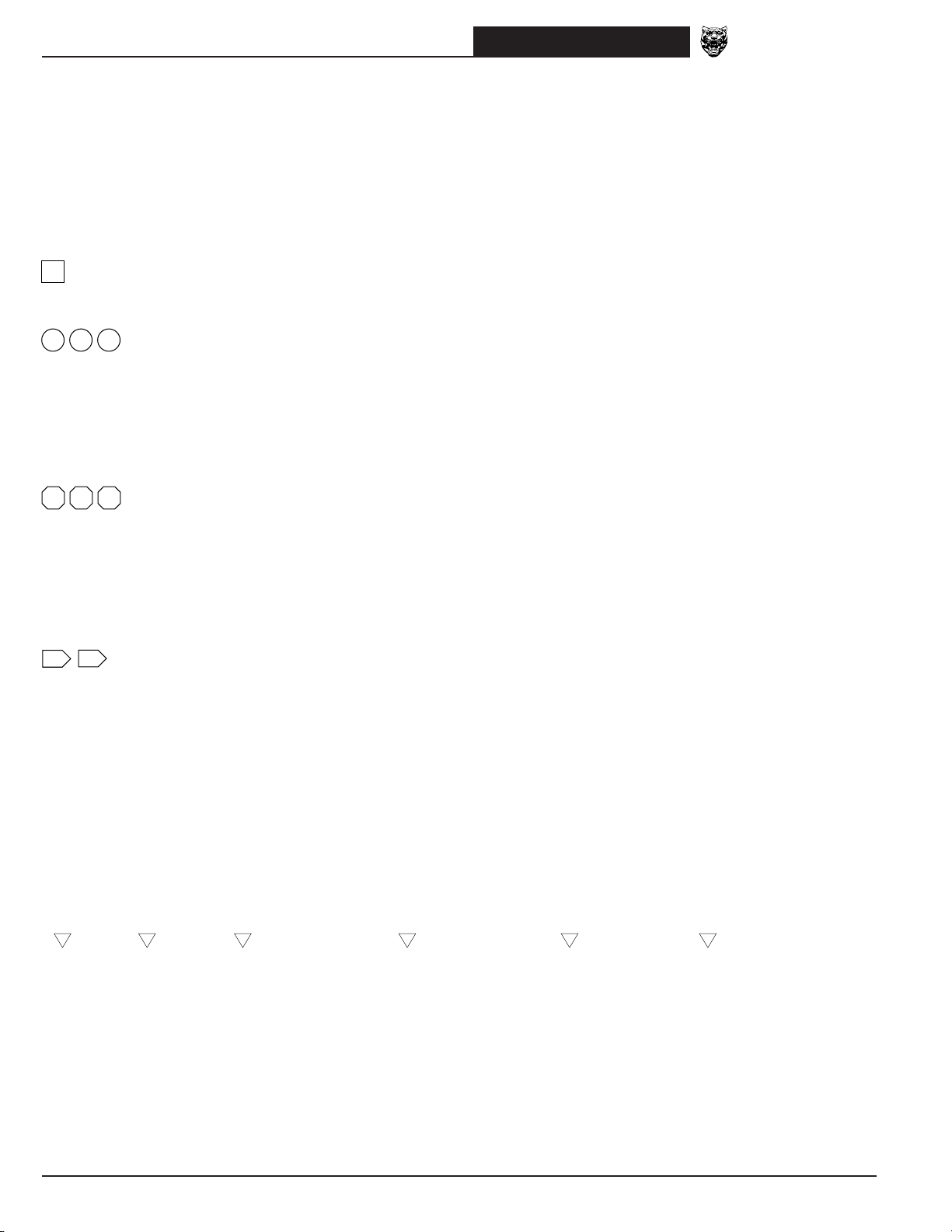
Grounds
HARNESS CODE + GROUND STUD NUMBER + EYELET STUD POSITION (A,B,C) + EYELET DESIGNATION (S,L,R)
Eyelet stud position
There may be up to three eyelets on one stud. A, B and C are used to indicate the position of the eyelet on the stud: A
– first (bottom), B – second (middle), C – third (top).
Eyelet designation
Two eyelet variations are used: a single eyelet and an eyelet pair. The single eyelet has a single ‘leg’, which is identified
by an S; the eyelet pair has two ‘legs’, identified as L (left) or R (right).
SLR
SINGLE EYELET EYELET PAIR
EXAMPLES:
Harness code
Ground stud number
Single leg eyelet
Third eyelet on stud
FC2S LF1AR BT1CSFC2S
Harness code
Ground stud number
Single leg eyelet
Harness code
Ground stud number
RH leg of eyelet
First eyelet on stud
Where the ground designation differs from LHD to RHD, the RHD ground is shown in parentheses. If the ground designation is the same for LHD and RHD, only one ground designation is used.
EXAMPLES:
EM2AR
(EM1AR)
LHD Vehicles
RHD Vehicles
BT1AL
Same for LHD & RHD Vehicles
DATE OF ISSUE: NOVEMBER 1998
15
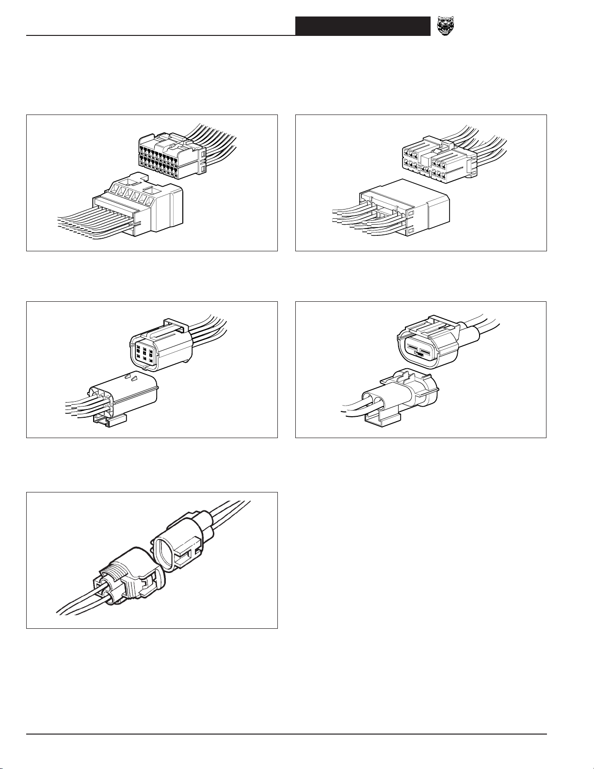
XK8 Range 1999Connectors
The following connectors are the common harness-to-harness connectors used throughout the vehicle.
Multilock 040
Low current (used as harness and ‘direct’ connection connector).
Econoseal III LC
Low current sealed connector.
Multilock 070
High current (used as harness and ‘direct’ connection connector).
Econoseal III HC
High current sealed connector.
Ford Card
Used for SRS only.
16
DATE OF ISSUE: NOVEMBER 1998

XK8 Range 1999
Main Power Distribution; Ground Point Identification and Location
Main Power Distribution; Ground Point Identification and Location
LF2
EM2
LF3
FC4
FC3
(QUIET GROUND)
GROUND POINTS
LF1
EM1
FC2
FC1
CE2
RADIO / CASSETTE
HEAD UNIT GROUND
ENGINE COMPARTMENT
ENGINE MANAGEMENT
FUSE BOX (RHD)
DRIVER SIDE FUSE BOX (LHD)
PASSENGER SIDE FUSE BOX (RHD)
FUSE BOX
EM70 EM70
MAIN POWER DISTRIBUTION
LF70
STARTER
MOTOR
RHD
RHD
BT79
EM71
FC91
LF71
TUNNEL
FC90
FC93
STUD CONNECTOR
GENERATOR
ST11
ST3
FALSE BULKHEAD
STUD CONNECTOR
BT80
ST1
FC90
FC92
ENGINE MANAGEMENT
FUSE BOX (LHD)
PASSENGER SIDE FUSE BOX (LHD)
DRIVER SIDE FUSE BOX (RHD)
FC6
RH3
(KEYFOB ANTENNA)
RH2
BT3
FC5
RH1
RADIO ANTENNA GROUND
BT68
BATTERY GROUND
BT1
BT2
PROTECTION MODULE
HIGH POWER
BT61
BT60
BT62
BT63
TRUNK FUSE BOX
BATTERY
+
–
BT66
BT67
BT68
BT64
DATE OF ISSUE: NOVEMBER 1998
17

Harness Layout
Harness Layout
XK8 Range 1999
FL – LH FRONT WHEEL
PI – ENGINE
LF – LEFT FORWARD
AC – AIR CONDITIONING
(CLIMATE CONTROL)
DD – DRIVER’S DOOR
SC – COLUMN SWITCHGEAR
SW – STEERING WHEEL
TL – TELEPHONE
DD1
FC4
LF3
LF3
LF40
LF1
LF2
LF60
SW1
SW2
LF41
LHD
FRONT OF VEHICLE
LF2
PI1
PI2
EM2 EM1
AC16
FC3
SC1
SC2
SC3
SC4
FC1
RHD
FRONT OF VEHICLE
LF1
LF42
FR – RH FRONT WHEEL
FL – LH FRONT WHEEL
LF41
ST – STARTER LINK
LL – POWER STEERING LINK
EL – ENGINE MANAGEMENT
LL1EM60
AC12
AC13
AC14
AC15
RF1
EL1
EM1
EM2
EM3
FC2
CRUISE CONTROL LINK
OR
EN – ENGINE MANAGEMENT
SIDE MARKER LINK
EM – ENGINE MANAGEMENT
DP1
DP – PASSENGER’S DOOR
AC – AIR CONDITIONING
(CLIMATE CONTROL)
DP – PASSENGER’S DOOR
PI – ENGINE
LF – LEFT FORWARD
DP1
FC4
LF3
LF3
LF40
LF1
LF2
LF60
RF – ROOF
FC – FASCIA
FC – FASCIA
TL – TELEPHONE
AC16
LF2
FC3
EM2
PI1
PI2
EM60
FC1
RF1
EM1
LF1
AC12
AC13
AC14
AC15
SC1
SC2
SC3
SC4
SW1
SW2
LF42
EL1
EM1
EM2
EM3
FC2
FR – RH FRONT WHEEL
ST – STARTER LINK
EL – ENGINE MANAGEMENT
CRUISE CONTROL LINK
OR
EN – ENGINE MANAGEMENT
SIDE MARKER LINK
EM – ENGINE MANAGEMENT
DD1
DD – DRIVER’S DOOR
SC – COLUMN SWITCHGEAR
SW – STEERING WHEEL
RF – ROOF
RT – RADIO TELEPHONE
IC – IN-CAR ENTERTAINMENT
SD – DRIVER’S SEAT
BT – TRUNK
QL – CONVERTIBLE
LH QUARTER LIGHT LINK
RL – LH REAR WHEEL
BB – TRUNK BRIDGING LINK
IC4
BT3
RT3
RH2
RT20
IC1
IC2
FC6
SD1
SD2
RH5 RH6
RH1
RH2
RH12
RH14
BB1
BL1BT72
SP1
SP2
FC5
RH1
BT2
BT1
BT1
BT2
BT3
BT4
BT58
BT73
SP – PASSENGER’S SEAT
RH – REARWARD
QR – CONVERTIBLE
RH QUARTER LIGHT LINK
RR – RH REAR WHEEL
BL – TRUNK LID
RT – RADIO TELEPHONE
IC – IN-CAR ENTERTAINMENT
SP – PASSENGER’S SEAT
BT – TRUNK
QL – CONVERTIBLE
LH QUARTER LIGHT LINK
RL – LH REAR WHEEL
BB – TRUNK BRIDGING LINK
IC4
BT3
RT3
RH2
RT20
IC1
IC2
FC6
SP1
SP2
RH5 RH6
RH1
RH2
RH12
RH14
BB1
BL1BT72
SD1
SD2
FC5
RH1
BT2
BT1
BT1
BT2
BT3
BT4
BT58
BT73
SD – DRIVER’S SEAT
RH – REARWARD
QR – CONVERTIBLE
RH QUARTER LIGHT LINK
RR – RH REAR WHEEL
BL – TRUNK LID
18
DATE OF ISSUE: NOVEMBER 1998

XK8 Range 1999
Control Module Identification and Location
LHD RHD
Control Module Identification and Location
RADIATOR FAN CONTROL
ABS / TRACTION CONTROL
BODY PROCESSOR MODULE
MAJOR INSTRUMENT PACK
KEY TRANSPONDER MODULE
RELAY MODULE
CONTROL MODULE
AIR CONDITIONING
CONTROL MODULE
DRIVER DOOR
CONTROL MODULE
DRIVER SEAT
CONTROL MODULE
GEAR SELECTOR
ILLUMINATION MODULE
TRANSMISSION CONTROL MODULE
ENGINE CONTROL MODULE
AIRBAG / SRS CONTROL MODULE
POWER ASSISTED STEERING
CONTROL MODULE
DIMMER MODULE
PASSENGER DOOR
CONTROL MODULE
PASSENGER SEAT
CONTROL MODULE
RADIATOR FAN CONTROL
ABS / TRACTION CONTROL
TRANSMISSION CONTROL MODULE
ENGINE CONTROL MODULE
MAJOR INSTRUMENT PACK
RELAY MODULE
CONTROL MODULE
PASSENGER DOOR
CONTROL MODULE
PASSENGER SEAT
CONTROL MODULE
GEAR SELECTOR
ILLUMINATION MODULE
BODY PROCESSOR MODULE
AIR CONDITIONING
CONTROL MODULE
AIRBAG / SRS CONTROL MODULE
KEY TRANSPONDER MODULE
DIMMER MODULE
DRIVER DOOR
CONTROL MODULE
POWER ASSISTED STEERING
CONTROL MODULE
DRIVER SEAT
CONTROL MODULE
ADAPTIVE DAMPING
CONTROL MODULE
DATE OF ISSUE: NOVEMBER 1998
SECURITY AND LOCKING
CONTROL MODULE
LAMP CONTROL MODULE
ADAPTIVE DAMPING
CONTROL MODULE
SECURITY AND LOCKING
CONTROL MODULE
LAMP CONTROL MODULE
19

Control Module Connector Pin Identification and Location
Control Module Connector Pin Identification and Location
XK8 Range 1999
ABS / TRACTION CONTROL CONTROL MODULE
LF37
LF37 / 25-WAY / BLACK
17W18R19UP20WU21P22U23
10—11—12—13UB14R15G16
TOP
1UO2US3S4G5Y6Y7
—
RY
O
24B25
WY
8B9
NR
TRANSMISSION CONTROL MODULE: AJ27 N/A
EM7
EM7 / 88-WAY / BLACK
28BY27—26ND25—24—23
55WB54WB53RU52RY51OB50—49—48—47—46—45RG44R43—42G41—40—39
88—87—86Y85G84—83Y82G81—80—79—78—77—76—75—74—73—72
BRD22UY21BU20—19—18BS17—16U15BRD14N13US12RP
ENGINE CONTROL MODULE: AJ27 N/A
23—24—25
1YU2BS3P4—5—6—7—8—9—10
11—10—9W8RB7
38—37Y36S35—34B33YP32YU31—30YB29
—
71—70—69—68—67—66—65—64—63—62—61—60—59—58—57—56
—
6B5OG4OK3—2RS1
—
OU
OR
TRANSMISSION CONTROL MODULE: AJ26 SC
EM73 EM72
EM73 / 18-WAY / BLACK EM72 / 14-WAY / BLACK
LGB26LGU27LGP28LGN29WB30B
—
—
33B34BY35BU36BO37BN38
12BG13BW14BK15
BLG16BP17BS
BR
LGH
Y
EM80 EM81 EM82 EM83 EM84
EM85
EM80 / 31-WAY / NATURAL EM81 / 24-WAY / NATURAL EM82 / 17-WAY / NATURAL EM83 / 28-WAY / NATURAL EM84 / 22-WAY / NATURAL EM85 / 12-WAY / WHITE
9GY8GY7R6R5G4G3
21B20PG19W18K17O16SP15SG14—13—12UG11UN10
31B30—29
BK
28—27
P
B
26—25RY24—23
2
OK*1PN
WU
ULG22RW
7RG6OG5W4WU3
16
RG*15SG14SR13WU12RU11—10U9K8B
24BG23—22
OU
PK
21B20—19G18R17
2RY1
OY
WR
6GR5G4R3—2GO1
12GP11W10Y9WK8US7
17UP16
Y
15O14UY13
UW
BG
WR
9N8Y7
19G18B17O16G15G14S13BG12BP11
28GY27BY26BY25Y24Y23
P
6BG5UW4KN3PU2—1
SLG10SG
N
22N21U20
NO
—
7PG6
BS
15PR14BG13BP12GU11GR10GO9GW8
22B21BN20GB19GS18
5BW4BY3BO2BU1
GK
17GP16
B
—
B
5U4
12—11
—
9
—
10
—
—
* NOT USED – ROW VEHICLES.
ENGINE CONTROL MODULE: AJ26 SC
EM14 EM15 EM13 EM12 EM11 EM10
EM14 / 12-WAY / WHITE EM15 / 22-WAY / WHITE EM13 / 34-WAY / GREY EM12 / 22-WAY / GREY EM11 / 16-WAY / GREY EM10 / 28-WAY / GREY
6R5R4BK3WR2GY1
12G11G10B9B8B7
GY
11
10—9—8—7BU6BW5BY4BO3
B
22
21—20—19—18BS17BN16
B
B
BG
15BP14
PN
2PU1
PS
13—12
—
B
10RY9KW8—7—6—5—4OK3SP2W1
16WU15
W
26
LGU25LGW24LGO23LGK22UB21—20B19Y18S17N
34
LPG33LGS
32
LGR31LGY
14GR13
PY
30—29
12RW11
28P27
O
KN
PW
BG
6YW5WU4YR3YN2YG1
11—10RY9
22BP21—20
SG
17U16N15R14G13GY12
—
YU
8
SLG7—
UP
19BY18
BY
4WU3P2—1
7
RG
11U10G9UY8
16K15R14BG13BY12
SR
6GO5
UW
SG
BG
8—7—6O5WK4UN3
13O12
K
21UW20BG19—18—17Y16PK15G14
28Y27G26Y25
11
PG
G
3—2PS1
8WG7B6
ULG2UG1WR
10US9
OU
24—23BK22
PU
B
NO
B
20
DATE OF ISSUE: NOVEMBER 1998
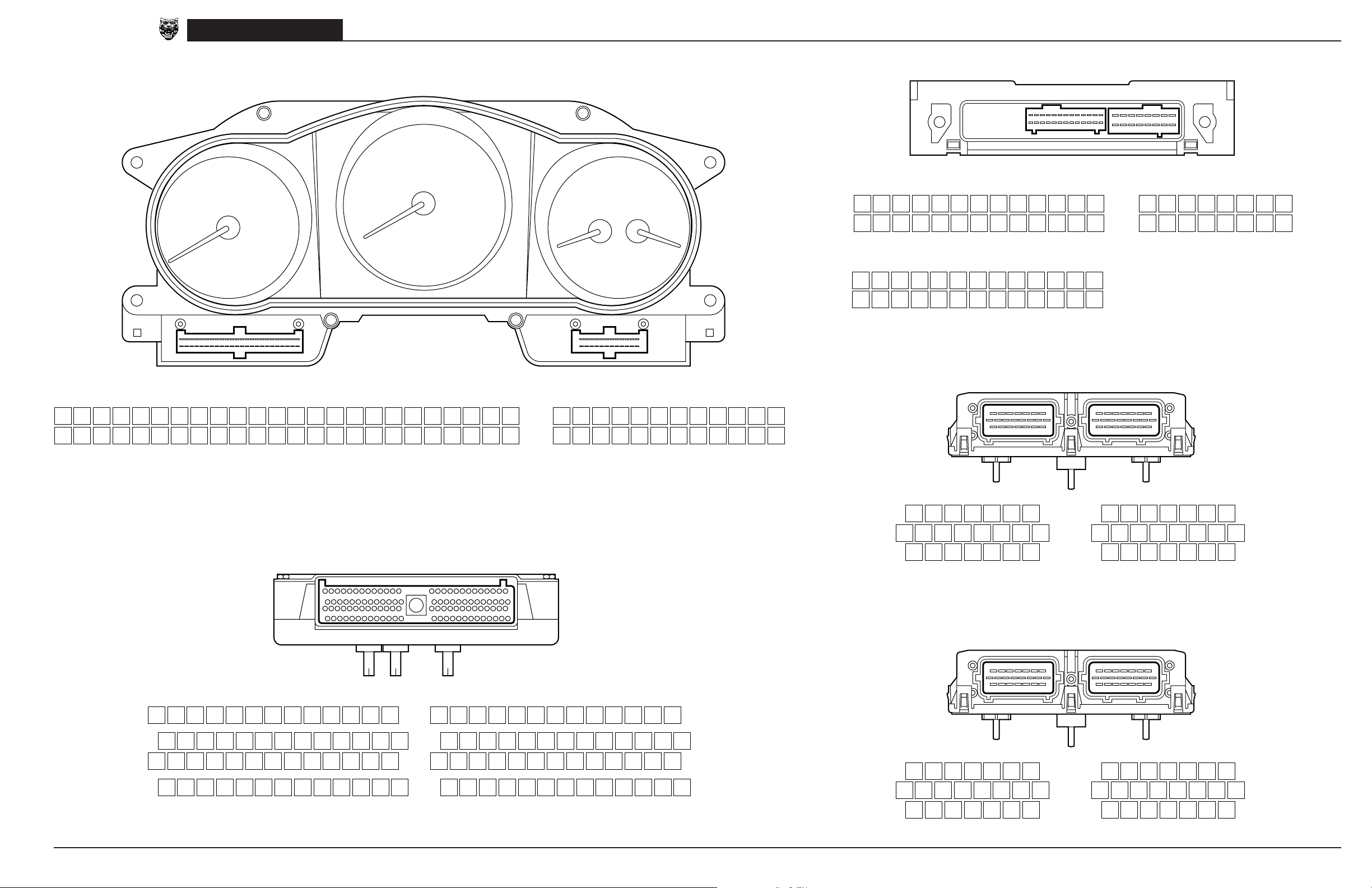
XK8 Range 1999
Control Module Connector Pin Identification and Location
MAJOR INSTRUMENT PACK
Control Module Connector Pin Identification and Location
SECURITY AND LOCKING CONTROL MODULE
BT41 BT40
FC25 / 48-WAY / BLACK FC26 / 24-WAY / BLACK
1BK2WG3RN4—5—6SO7—8—9—10SU11—12—13UY14R15—16—17
25NR26B27RO28RO29—30—31—32—33BR34—35Y36O37—38—39—40—41
BODY PROCESSOR MODULE
18—19S20U21—22—23Y24
—
42—43—44—45—46—47G48
—
BT41 / 26-WAY / BLACK (NAS)
13—12—11—10—9—8—7YP6—5RY4—3
26—25—24—23—22—21—20—19YR18—17—16—15—14
LGY2—1R
—
BT40 / 16-WAY / BLACK
8S7OG6NK5YW4GW3UG2OB1
16U15NY14BK13BK12—11UO10—9
OR
GR
BT41 / 26-WAY / BLACK (ROW)
13—12—11—10BK9—8
26YO25—24—23—22—21—20—19YR18—17—16—15—14
FC26FC25
—
G
1RK2OW3PY4SG5
13BW14RW15OU16YW17
6UB7ON8RG9RS10OB11RB12
OU
18OG19OS20UW21
OS
RLG22SW23OP24UR
RU
LGS7—6—5RY4—3—2—1—
—
DRIVER DOOR CONTROL MODULE
DD11 DD10
DD11 / 22-WAY / BLACK DD10 / 22-WAY / BLUE
7BP6KS5
15WG14—13—12OY11—10YO9YN8
22UN21UP20GY19—18—17OR16
LGU4OU3SN2UG1OB
—
—
7OB6SU5SY4PN3PG2BY1
15OU14GW13PO12PW11PB10BG9U8
22PK21PU20WU19BR18BO17B16
N
S
BK
79NG80NB81GR82GR83GB84U85S86ON87SK88YG89
53RK54RB55SP56UW57—58SB59PY60RY61KG62
27GO28RW29S30U31SW32WN33RG34
1RY2GY3GK4GU5SO6YW7RU8—9
DATE OF ISSUE: NOVEMBER 1998
FC14 / 104-WAY / GREY
LGR90BG91BW
LGU63SW64—65BK
LGK35OU36LGW37LGR38OR39Y
LGU10SR11YB12OP13GO*
* NOT USED – NAS VEHICLES.
FC14
92SU93YK94
40WU41RW42UY43
LGO95RS96PW97—98GB99PN
66PU67UR68US69OK70GS71SR72—73GO74RW75—76GK77GP78
BLG44OY45UG46—47—48OG49—50GY51RW52BS
14UB15WO16RY17OS18YS19
WLG20OG21—22WB23WO24NW25B26YG
100BR101PW102NY103B104
NY
PG
PASSENGER DOOR CONTROL MODULE
DP11 DP10
DP11 / 22-WAY / BLACK DP10 / 22-WAY / BLUE
7—6—5
15—14—13—12—11—10—9—8
22—21—20GY19—18—17—16
LGU4—3—2—1—
—
—
7OB6SU5SY4PN3PG2PY1
15OU14GW13PO12PW11PB10BG9U8
22PK21PU20WU19—18BO17B16
N
BK
S
21
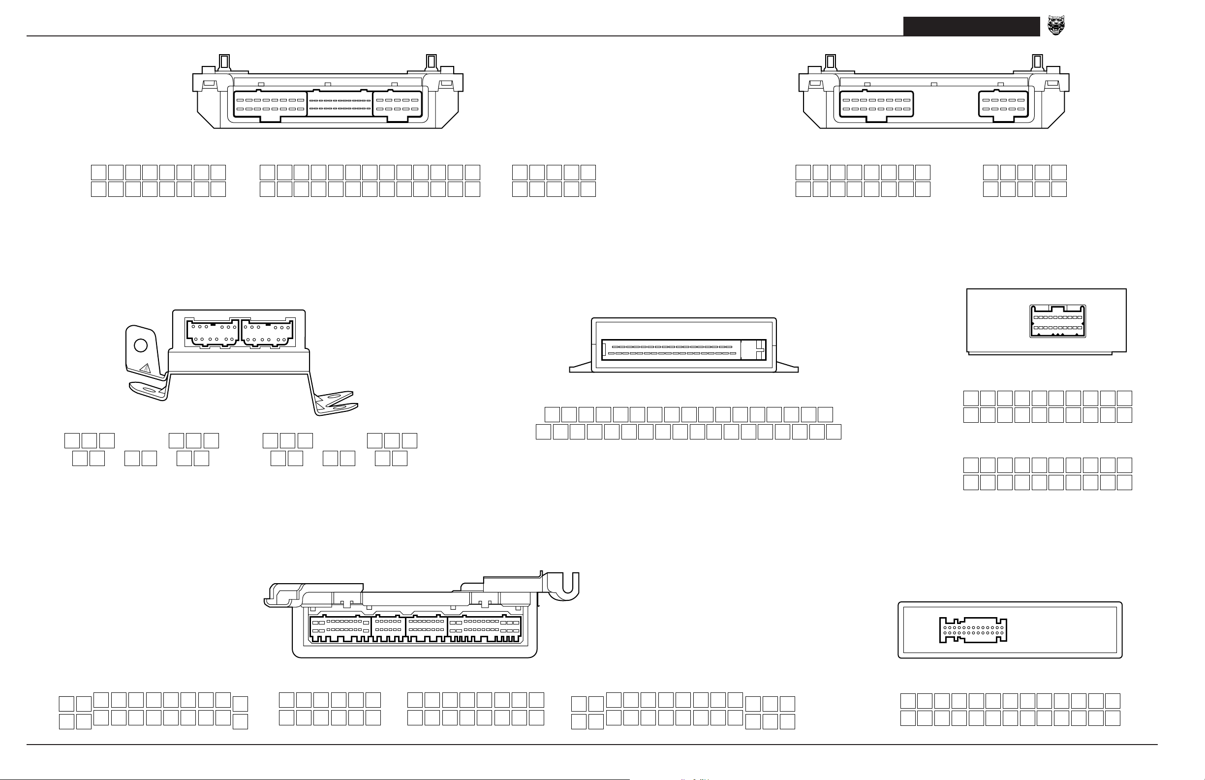
Control Module Connector Pin Identification and Location
Control Module Connector Pin Identification and Location
XK8 Range 1999
DRIVER SEAT CONTROL MODULE
SD3 SD4 SD5
SD3 / 16-WAY / BLACK SD4 / 26-WAY / BLACK SD5 / 10-WAY / BLACK
9UY10UW11KW12KY13GN14GP15GW16
1PS2PO3OK4R5OB6OR7KS8
GY
KO
14WP15—16—17—18WB19—20—21—22—23—24—25—26
1WG2WU3B4—5W6WN7—8—9—10WR11WY12WO13
—
—
6—7—8G9S10
1B2B3US4UO5
AIRBAG / SRS CONTROL MODULE
FC29 FC30
NK
PASSENGER SEAT CONTROL MODULE
SP3 SP5
SP3 / 16-WAY / BLACK SP5 / 10-WAY / BLACK
U
9UY10UW11KW12KY13GN14GP15GW16
1PS2PO3OK4R5OB6OR7KS8
GY
KO
6—7—8G9S10
1B2B3US4UO5
U
NK
KEY TRANSPONDER MODULE
ADAPTIVE DAMPING CONTROL MODULE
BT69
FC22
7WK8OW9
1—2
—
FC29 / 12-WAY / BLACK FC30 / 12-WAY / GREY
OP
3—4
BK
10—11YU12
5YW6
R
ON
12 BK11RS10
6WK5
RG
KU
4KP3
KN
AIR CONDITIONING CONTROL MODULE
AC4 AC3 AC2 AC1
9KG8RW7
2RP1
—
RW
BT69 / 35-WAY / BLACK
19—20PB21UB22RB23—24ON25U26US27NS28K29—30OB31OW32OK33OY34OU35
1SO2UP3UW4—5—6—7—8—9—10O11WR12—13OR14OG15OP16—17—18
—
FC22 / 20-WAY / GREEN (NAS)
10—9SU8—7—6O5—4—3—2—1
20—19—18—17Y16O15—14—13—12—11
B
—
—
FC22 / 20-WAY / GREEN (ROW)
10—9SU8OG7OR6O5—4NR3—2—1
20—19—18—17Y16O15—14WO13WN12BK11
SB
—
LAMP CONTROL MODULE
BT18
22
12WR13
1WP2
GY
AC4 / 22-WAY / GREY AC3 / 12-WAY / GREY AC2 / 16-WAY / GREY AC1 / 26-WAY / GREY
14B15GW16OU17UB18
B
3WN4WU5NY6PY7UG8P9UN10
LGW19BW20BK21O
BT18 / 26-WAY / YELLOW
22
—
11
K
—
7SY8SR9—10WP11UB12
1
ULG2S3SG4SB5OY6UG
KU
9OU10OR11YG12—13UY14—15UK16
1OP2RG3YW4—5SU6SG7US8
GP
GO
14—15
1
RLG2U
16
LGN17RW18LGP19RU20SR21Y22NR23—
—
3UY4PS5
LGR6RY7PR8PY
9RB10
—
24—25UR26
11—12UW13
GU
UO
1—2—3—4—5—6—7—8—9—10—11—12—13
14UP15UO16RY17RK18RU19UB20UW21RO22RG23RW24WG25R26
DATE OF ISSUE: NOVEMBER 1998
—
BK
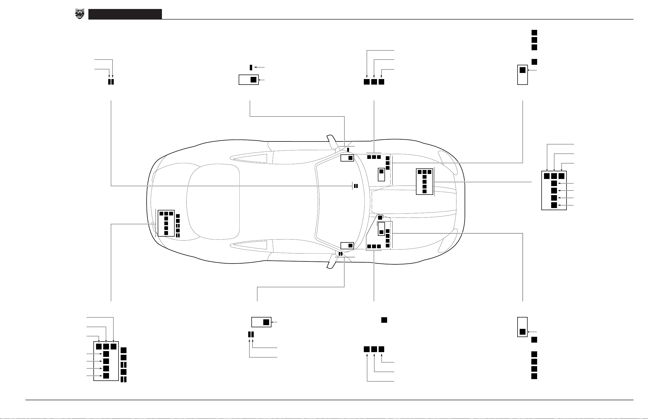
LH blower motor relay
RH blower motor relay
black
black
XK8 Range 1999 Relay and Fuse Box Identification and Location
Wiper FAST/SLOW relay
black
Wiper RUN/STOP relay
black
Air conditioning compressor clutch relay
brown
Driver side fuse box (LHD)
Passenger side fuse box (RHD)
Door mirror heater relay
black
Ignition positive relay (LHD)
Auxiliary positive relay (RHD)
brown
Engine Management
fuse box
Relay and Fuse Box Identification and Location
Fuel injection relay
brown
Throttle motor power relay
brown
Ignition coil relay
brown
O2S heaters relay (AJ27 only)
brown
EMS control relay
brown
DRIVESHAFT TUNNEL RELAYS
LH FASCIA RELAYS
LH ENCLOSURE RELAYS
CONTROL MODULE ENCLOSURE RELAYS (RHD)
Engine compartment
fuse box
ENGINE COMPARTMENT FUSE BOX RELAYS
Heater pump relay
brown
Front fog relay
brown
Main beam relay
brown
Powerwash relay
brown
Dip beam relay
brown
Horn relay
brown
Ignition positive relay
brown
Tail lamp relay
brown
Heated backlight relay
Fuel pump 1 relay
Accessory connector relay
Ignition positive relay
DATE OF ISSUE: NOVEMBER 1998
brown
Rear fog relay
brown
brown
Stop lamp relay
brown
brown
brown
TRUNK RELAYS
Trunk fuse box
Top up relay
black
Top down relay
black
LH quarter up relay / LH quarter down relay
black
Fuel pump 2 relay
brown
RH quarter up relay / RH quarter down relay
black
RH FASCIA RELAYS
Passenger side fuse box (LHD)
Driver side fuse box (RHD)
Auxiliary positive relay (LHD)
Ignition positive relay (RHD)
brown
Door locking relay
black
Air conditioning isolate relay
black
RH ENCLOSURE RELAYS
Intercooler pump relay (RHD)
brown
Starter relay
brown
LH windshield heater relay
brown
RH windshield heater relay
brown
CONTROL MODULE ENCLOSURE RELAYS (LHD)
Engine Management
fuse box
EMS control relay
brown
O2S heaters relay (AJ27 only)s
brown
Intercooler pump relay (LHD)
brown
Fuel injection relay
brown
Throttle motor power relay
brown
Ignition coil relay
brown
23

CONTROL MODULE PIN OUT INFORMATION
Fig. 01.1
BODY PROCESSOR MODULE
Pin Description Active Inactive
I FC14-15 IGNITION SWITCHED GROUND SUPPLY GROUND
I FC14-32 IGNITION SWITCHED GROUND SUPPLY GROUND GROUND
O FC14-97 RELAY COIL DRIVE
COMPONENTS
Component Connector / Type / Color Location / Access
BATTERY BT66 / EYELET TRUNK, RIGHT HAND SIDE
BODY PROCESSOR MODULE FC14 / 104-WAY AMP EEEC / GREY PASSENGER SIDE FASCIA / AIRBAG BRACKET
FUSE BOX – DRIVER SIDE FC5 / 10-WAY U.T.A. FUSEBOX / NATURAL FASCIA / DRIVER SIDE
FUSE BOX – ENGINE COMPARTMENT LF5 / 10-WAY U.T.A. FUSEBOX / NATURAL ENGINE COMPARTMENT / LEFT FRONT
FUSE BOX – ENGINE MANAGEMENT EM19 / 10-WAY U.T.A. FUSEBOX / NATURAL ENGINE COMPARTMENT / CONTROL MODULE ENCLOSURE
FUSE BOX – PASSENGER SIDE FC20 / 10-WAY U.T.A. FUSEBOX / NATURAL FASCIA / PASSENGER SIDE
FUSE BOX – TRUNK BT10 / 10-WAY U.T.A. FUSEBOX / NATURAL TRUNK / ELECTRICAL CARRIER
HIGH POWER PROTECTION MODULE BT60 / EYELET TRUNK / ADJACENT TO BATTERY
TRANSIT ISOLATION DEVICE BT44 / 2-WAY ECONOSEAL III HC / BLACK TRUNK / ADJACENT TO BATTERY
BT67 / EYELET
FC6 / 10-WAY U.T.A. FUSEBOX / BLACK
FC90 / EYELET
FC92 / EYELET
LF6 / 10-WAY U.T.A. FUSEBOX / BLACK
LF7 / 10-WAY U.T.A. FUSEBOX / GREEN
LF8 / 10-WAY U.T.A. FUSEBOX / BLUE
LF70 / EYELET
EM20 / 10-WAY U.T.A. FUSEBOX / BLACK
EM70 / EYELET
FC21 / 10-WAY U.T.A. FUSEBOX / BLACK
FC90 / EYELET
FC93 / EYELET
BT11 / 10-WAY U.T.A. FUSEBOX / BLACK
BT12 / 10-WAY U.T.A. FUSEBOX / GREEN
BT13 / 10-WAY U.T.A. FUSEBOX / BLUE
BT64 / EYELET
BT61 / EYELET
BT62 / EYELET
BT63 / EYELET
BT49 / 1-WAY LUCAR
BT65 / EYELET
BT66 / EYELET
RELAYS
Relay Color / Stripe Connector / Color Location / Access
AUXILIARY POSITIVE RELAY BROWN BUS PASSENGER SIDE FUSE BOX
EMS CONTROL RELAY BROWN BUS ENGINE MANAGEMENT FUSE BOX
IGNITION POSITIVE RELAY BROWN BUS DRIVER SIDE FUSE BOX
IGNITION POSITIVE RELAY BROWN BUS ENGINE COMPARTMENT FUSE BOX
IGNITION POSITIVE RELAY BROWN BUS TRUNK FUSE BOX
The following symbols are used to represent values for Control Module Pin Out data:
I Input
O Output
SG Signal Ground
D Serial and encoded communications
C CAN (Network)
S SCP Network
B+ Battery voltage
V Voltage (DC)
Hz Frequency
KHz Frequency x 1000
MS Milliseconds
MV Millivolts
CAUTION: The information on this data page is furnished to aid the user in understanding circuit operation. THIS INFORMATION SHOULD BE USED FOR
REFERENCE ONLY.
NOTE: The values listed are approximately those that can be expected at the control module connector pins with all circuit connections made and all
components connected and fitted. “Active” means a load is applied or a switch is ON; “Inactive” means a load is not applied or a switch is OFF.
HARNESS-TO-HARNESS CONNECTORS
Connector Type / Color Location / Access
BT2 20-WAY MULTILOCK 070 / WHITE TRUNK / ABOVE RIGHT HAND REAR WHEEL ARCH
BT79 EYELET TRANSMISSION TUNNEL
BT80 EYELET ENGINE COMPARTMENT / FALSE BULKHEAD, RIGHT HAND SIDE
EM71 EYELET TRANSMISSION TUNNEL
FC91 EYELET TRANSMISSION TUNNEL
LF71 EYELET TRANSMISSION TUNNEL
RH2 20-WAY MULTILOCK 070 / WHITE REAR OF CENTER CONSOLE ASSEMBLY
ST1 EYELET ENGINE COMPARTMENT / FALSE BULKHEAD, RIGHT HAND SIDE
GROUNDS
Ground Location / Type
BT68 BATTERY GROUND STUD
BT2BR EYELET (PAIR) – RIGHT HAND LEG / TRUNK, RIGHT REAR
BT2BS EYELET (SINGLE) / TRUNK, RIGHT REAR
CONTROL MODULE PIN OUT INFORMATION (FOLD OUT PAGE)
REFER TO THE FRONT OF THE BOOK FOR ILLUSTRATIONS DETAILING THE LOCATION AND IDENTIFICATION OF COMPONENTS, RELAYS,
CONNECTORS, HARNESSES, GROUNDS, VEHICLE CONTROL MODULES AND CONTROL MODULE PINS.
DATE OF ISSUE: NOVEMBER 1998
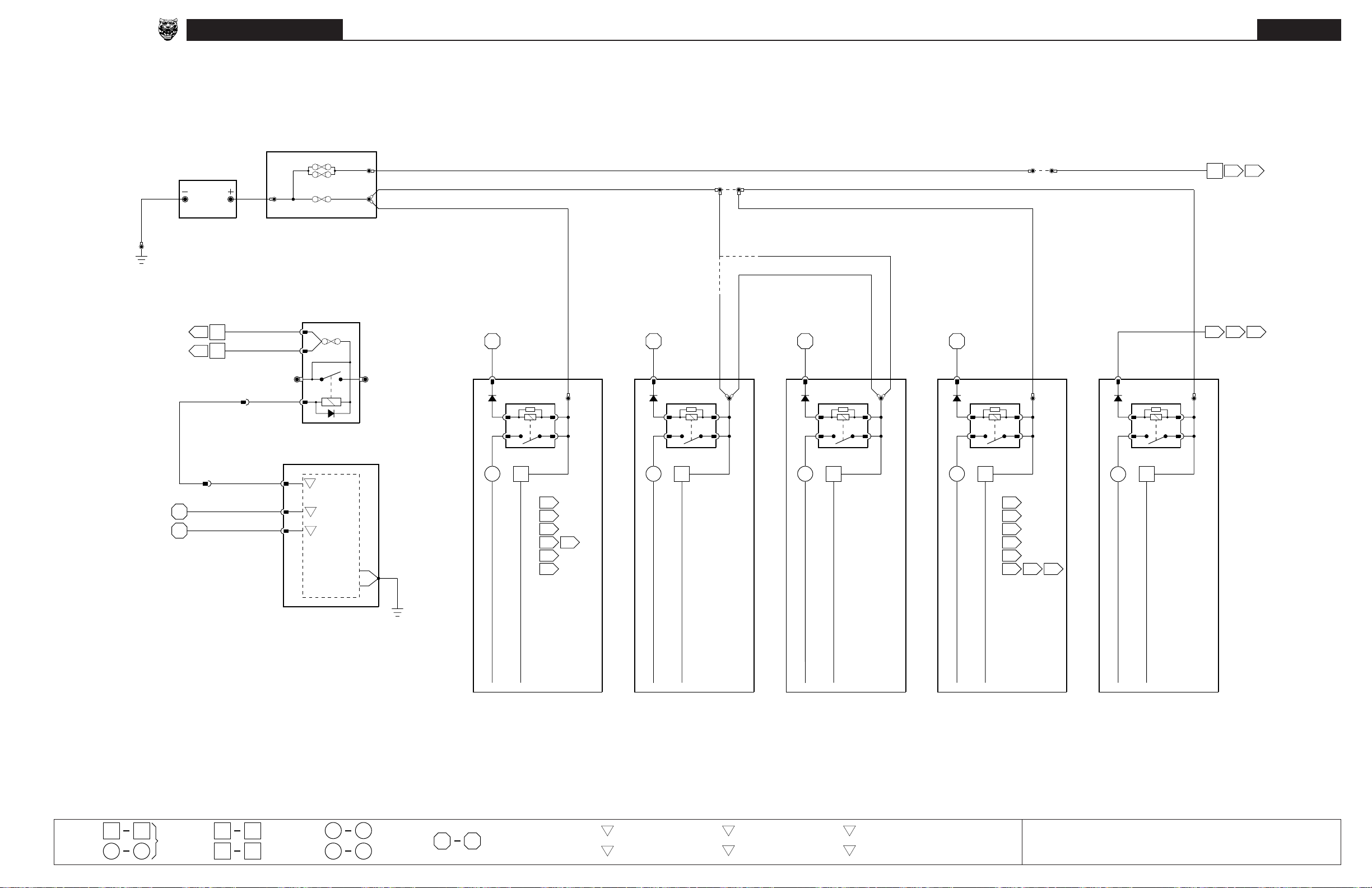
XK8 Range 1999
Main Power Distribution
Main Power Distribution
Fig. 01.1
B
BT68
DRIVER DOOR CONTROL MODULE:
WINDOW LIFT OPERATION
PASSENGER DOOR CONTROL MODULE:
(CIRCUIT CONTINUED)
WINDOW LIFT OPERATION
(CIRCUIT CONTINUED)
250A x 2
N
BT67 BT66
BATTERY HIGH POWER
26
15.1
48
15.1
BATTERY POST
BT60 BT63
PROTECTION MODULE
NO
BT44-2
NY
BT44-1
(BT65)
KY KY
BT2-14
BT49
ISOLATION DEVICE
KY
WO
WN
FC14-97
FC14-15
FC14-32
RH2-20
5
II
16
I
O
I
I
250A
25 A
TRANSIT
LOGIC
POWER
BT61
BT62
B+
(BT66)
TUNNEL
N
N
N
STUD CONNECTOR
BT79
FC91
EM71
LF71
N
N
N
FALSE BULKHEAD
STUD CONNECTOR
BT80
ST1
N
6
03.1
03.2
STARTER
N
(RHD)
(LHD)
12
II
RG
BT12-9
IGNITION POSITIVE
1
II
13
I
N
BT64 FC90
2
5
1
3
RELAY
1
1
09.2
2
07.2
3
09.2
4
04.3
04.5
5
09.2
6
18.1 18.1
RELAYS
WN N
FC21-6
2
1
3
5
AUXILIARY POSITIVE
RELAY
2
2
I
N
FC93
11
II
RG
FC6-6
1
5
IGNITION POSITIVE
RELAY
3
3 4
II
N
FC92 FC90
2
3
N
10
II
RG
LF7-9
2
5
IGNITION POSITIVE
4
II
RELAY
1
2
3
4
5
6
1
3
07.2
09.1
09.1
14.1
09.1
13.2
RELAYS
LF70
13.3
PK
N
EM20-6
2
1
3
5
EMS CONTROL
RELAY
5
5
E
EM70
04.1
04.2
N
ECM CONTROL
04.4
(CIRCUIT CONTINUED)
1 7 516
1
II
5
E
Fig. 01.1
52 85
BODY PROCESSOR
Fig. 01.2
Fig. 01.3
MODULE
6
II
42
E
41
II
60
E
Fig. 01.4
Fig. 01.5
IGNITION POWER BUS
IGNITION AUXILIARY POWER BUS
BATTERY POWER BUS
IGNITION POWER BUS
TRUNK FUSE BOX PASSENGER SIDE
I
18
I
Fig. 02.1
1
Input Output
Signal Ground (SG) CAN (Network) SCP Network
BATTERY POWER BUS
FUSE BOX
BATTERY POWER BUS
DRIVER SIDE
FUSE BOX
Serial and Encoded
DO
Communications
SC
IGNITION POWER BUS
BATTERY POWER BUS
ENGINE COMPARTMENT
FUSE BOX
VARIANT: All Vehicles
VIN RANGE: 031303
DATE OF ISSUE: NOVEMBER 1998
BATTERY POWER BUS
ENGINE MANAGEMENT POWER BUS
ENGINE MANAGEMENT
FUSE BOX
➞

Fig. 01.2
COMPONENTS
Component Connector / Type / Color Location / Access
FUSE BOX – DRIVER SIDE FC5 / 10-WAY U.T.A. FUSEBOX / NATURAL FASCIA / DRIVER SIDE
FUSE BOX – PASSENGER SIDE FC20 / 10-WAY U.T.A. FUSEBOX / NATURAL FASCIA / PASSENGER SIDE
HARNESS-TO-HARNESS CONNECTORS
Connector Type / Color Location / Access
AC12 20-WAY MULTILOCK 070 / WHITE FASCIA TOP CONNECTOR MOUNTING BRACKET / RIGHT HAND SIDE
AC13 20-WAY MULTILOCK 070 / YELLOW FASCIA BOTTOM CONNECTOR MOUNTING BRACKET / RIGHT HAND SIDE
AC14 14-WAY MULTILOCK 070 / GREY FASCIA BOTTOM CONNECTOR MOUNTING BRACKET / RIGHT HAND SIDE
AC15 20-WAY MULTILOCK 070 / GREY FASCIA BOTTOM CONNECTOR MOUNTING BRACKET / RIGHT HAND SIDE
AC16 6-WAY MULTILOCK 070 / YELLOW LEFT HAND ‘A’ POST CONNECTOR MOUNTING BRACKET / ‘A’ POST TRIM
BT2 20-WAY MULTILOCK 070 / WHITE TRUNK / ABOVE RIGHT HAND REAR WHEEL ARCH
BT58 4-WAY ECONOSEAL III HC / BLACK TRUNK / ABOVE RIGHT HAND REAR WHEEL ARCH
DD1 23-WAY AMP – FORD / BLACK DRIVER SIDE ‘A’ POST MOUNTING BRACKET/ ‘A’ POST TRIM
DP1 23-WAY AMP – FORD / BLACK PASSENGER SIDE ‘A’ POST / ‘A’ POST TRIM
IC2 14-WAY MULTILOCK 070 / WHITE BELOW CENTER CONSOLE GLOVE BOX
LF1 20-WAY MULTILOCK 070 / GREY LEFT HAND ‘A’ POST CONNECTOR MOUNTING BRACKET / ‘A’ POST TRIM
RF1 18-WAY MULTILOCK 070 / YELLOW RIGHT HAND ‘A’ POST CONNECTOR MOUNTING BRACKET / ‘A’ POST TRIM
RH14 2-WAY ECONOSEAL III HC / BLACK REAR OF CENTER CONSOLE ASSEMBLY
RH2 20-WAY MULTILOCK 070 / WHITE REAR OF CENTER CONSOLE ASSEMBLY
SD1 8-WAY MULTILOCK 070 / YELLOW BELOW DRIVER SEAT
SP1 8-WAY MULTILOCK 070 / YELLOW BELOW PASSENGER SEAT
FC6 / 10-WAY U.T.A. FUSEBOX / BLACK
FC90 / EYELET
FC92 / EYELET
FC21 / 10-WAY U.T.A. FUSEBOX / BLACK
FC90 / EYELET
FC93 / EYELET
REFER TO THE FRONT OF THE BOOK FOR ILLUSTRATIONS DETAILING THE LOCATION AND IDENTIFICATION OF COMPONENTS, RELAYS,
CONNECTORS, HARNESSES, GROUNDS, VEHICLE CONTROL MODULES AND CONTROL MODULE PINS.
DATE OF ISSUE: NOVEMBER 1998
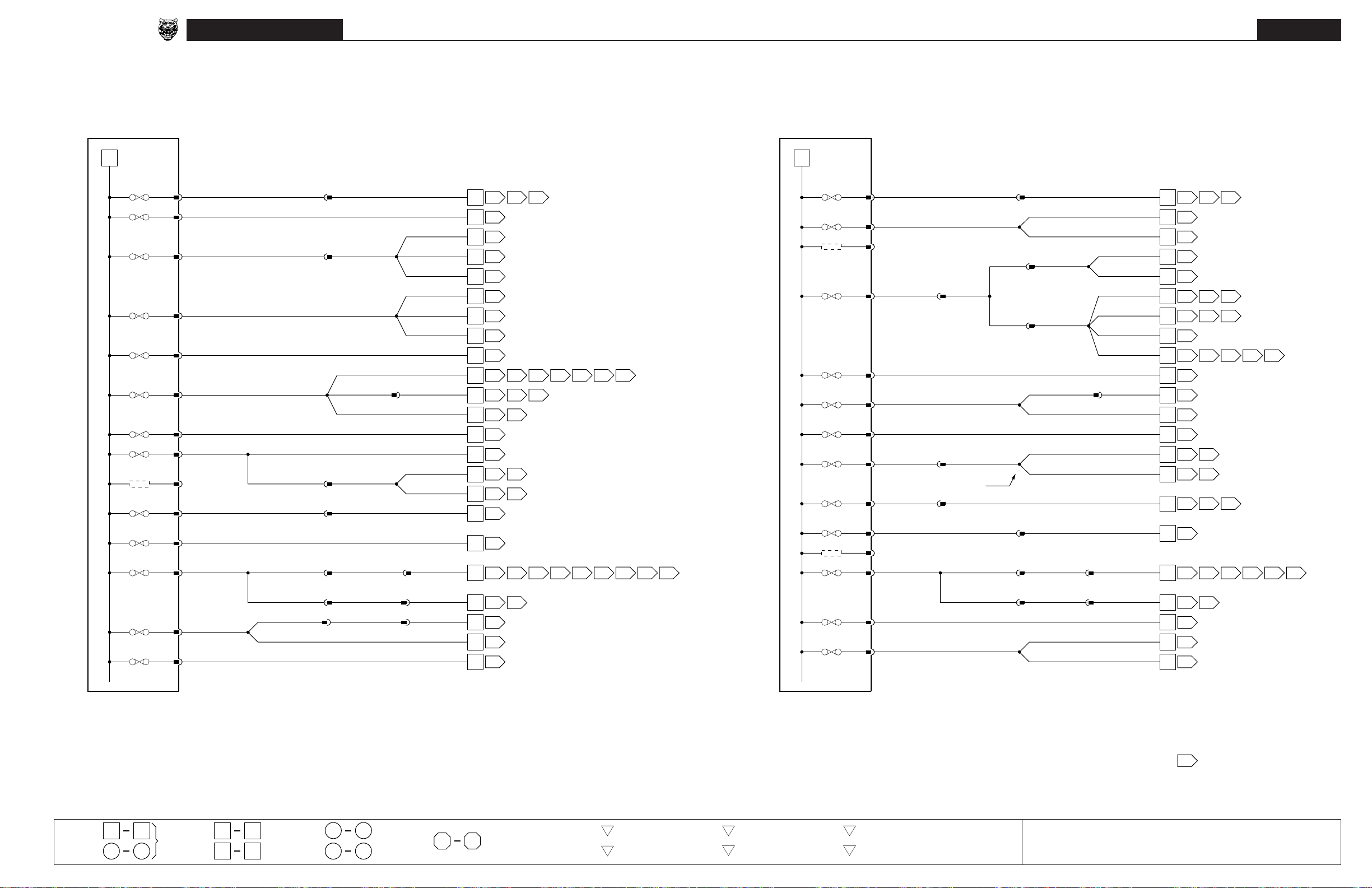
XK8 Range 1999
Battery Power Distribution: Driver and Passenger Side Fuse Boxes
23
Battery Power Distribution:
Driver and Passenger Side Fuse Boxes
Fig. 01.2
#1 20A
#2 10A
BATTERY POWER BUS
#3 30A
#4 10A
#5 15A
#6 5A
#7 15A
#8 5A
#9
#11 20A
#13 5A
#15 25A
#17 10A
#18 5A
NK
FC6
-1
NS
FC6
-5
NU
FC6
-3
RW
FC6
-8
NB
FC5
-9
NR
FC5
-10
NY
FC5
-4
NP
FC5
-7
FC5
-2
FC6
-2
FC6
-4
FC5
-3
FCS5
NP
NW (LHD) NU (RHD)
NY NY
NO
FCS81
NO
NO
SD1-2
LF1-20
FCS19
SD1-5
AC16-3 (LHD)
AC15-2 (RHD)
AC16-1 (LHD)
AC15-20 (RHD)
RH2-8
NU
LFS20
FCS39
N
SDS6
NW (LHD) NU (RHD)
NO
NO NO
NLG NLG NLG
FC5
-1
FC5
-6
NLG
NR
FCS40
RH14-2
RF1-7
DD1-22
BT2-8
BT58-2
NK
NS
NU
NU
NU
RW
RW
RW
NB
NR
NRNR
NR
NY
NP
N
N
N
NLG
NR
11.4
07.2
14.1
14.1
14.1
17.1
17.1
17.1
BPM
06.1
13.2
13.2
BPM
11.2
12.1
12.1
07.2
19.1
10.1
01.1
18.1
18.1
08.1
12.1 12.2
09.1 09.2
13.3
13.3
12.2
12.2
11.2
15.1
12.1 12.2 12.3
18.1
11.3 11.4 12.1 13.1 13.2 15.1
12.4
13.3
#1 20A FC21
#2 10A FC21
#3 FC21
BATTERY POWER BUS
#4 5A FC21
#5 5A FC20
#6 10A FC20
#7 20A FC20
#8 5A FC20
#9 10A FC20
#11 20A FC21
#13 FC21
#15 25A FC20
#17 15A FC20
#18 10A FC20
7
8
9
10
11
12
13
14
15
16
17
18
19
20
21
22
23
24
25
26
27
28
29
NK
-1
NR
-5
-3
NW
-8
NP
-9
NY
-10
NB
-4
N
-7
NOTE: SPS1 – 3-way seat only.
NP
-2
NU (LHD) NW (RHD)
-2
-4
NY
-3
FCS82
NG
-1
NP
-6
AC13-14
SP1-5
IC2-13
NW
ACS3
N
NY
NY
SP1-2
FCS89
NW
DP1-4
NW
DD1-4
FCS23
SPS1
AC15-2 (LHD)
AC16-3 (RHD)
AC15-20 (LHD)
AC16-1 (RHD)
RH2-13
FCS88
NW
DPS2
NW
DDS2
NY NY
AC12-20
NU (LHD) NW (RHD)
NY
DP1-22
NY
BT2-2
NK
NR
NR
NW
NW
NW
NW
NW
NW
NP
NY
NB
N
N
NP
N
NY
NG
NP
NP
11.4
12.3
30
13.1
31
13.1
32
13.1
33
15.1
34
11.2
35
11.3
36
13.1
37
10.1
38
16.4
39
07.1
40
07.1
41
11.2
42
12.3
43
12.3
44
16.1
45
07.2
46
10.1
47
01.1
48
BPM
49
10.2
50
10.2
51
12.4
11.3
12.1
11.4 15.1
13.1
13.2 15.1
13.3
12.4
12.4
16.2 16.3
11.3 13.1 13.2 15.1
15.1
13.3
DRIVER SIDE
FUSE BOX
1 7 516
5
1
E
II
Fig. 01.1
52 85
Fig. 01.2
Fig. 01.3
PASSENGER SIDE
FUSE BOX
NOTE: Body Processor Module
BPM
appears in numerous Figures.
6
41
II
60
E
Fig. 01.4
Fig. 01.5
18
I
Fig. 02.1
1
II
42
E
I
Input Output
Signal Ground (SG) CAN (Network) SCP Network
Serial and Encoded
DO
Communications
SC
VARIANT: All Vehicles
VIN RANGE: 031303
DATE OF ISSUE: NOVEMBER 1998
➞

Fig. 01.3
COMPONENTS
Component Connector / Type / Color Location / Access
FUSE BOX – ENGINE COMPARTMENT LF5 / 10-WAY U.T.A. FUSEBOX / NATURAL ENGINE COMPARTMENT / LEFT FRONT
FUSE BOX – ENGINE MANAGEMENT EM19 / 10-WAY U.T.A. FUSEBOX / NATURAL ENGINE COMPARTMENT / CONTROL MODULE ENCLOSURE
FUSE BOX – TRUNK BT10 / 10-WAY U.T.A. FUSEBOX / NATURAL TRUNK / ELECTRICAL CARRIER
HARNESS-TO-HARNESS CONNECTORS
Connector Type / Color Location / Access
IC4 4-WAY MULTILOCK 070 / WHITE TRUNK / LEFT OF ANTENNA ASSEMBLY
LF6 / 10-WAY U.T.A. FUSEBOX / BLACK
LF7 / 10-WAY U.T.A. FUSEBOX / GREEN
LF8 / 10-WAY U.T.A. FUSEBOX / BLUE
LF70 / EYELET
EM20 / 10-WAY U.T.A. FUSEBOX / BLACK
EM70 / EYELET
BT11 / 10-WAY U.T.A. FUSEBOX / BLACK
BT12 / 10-WAY U.T.A. FUSEBOX / GREEN
BT13 / 10-WAY U.T.A. FUSEBOX / BLUE
BT64 / EYELET
REFER TO THE FRONT OF THE BOOK FOR ILLUSTRATIONS DETAILING THE LOCATION AND IDENTIFICATION OF COMPONENTS, RELAYS,
CONNECTORS, HARNESSES, GROUNDS, VEHICLE CONTROL MODULES AND CONTROL MODULE PINS.
DATE OF ISSUE: NOVEMBER 1998
 Loading...