

Page 1

jaguar :: Jaguar XJ-S Convertible (XJ27) L6-4.0L
(1996)
Page 2
> Relays and Modules > Relays and Modules - Accessories and Optional Equipment > Alarm Module, (Vehicle Antitheft) > Component Information > Locations
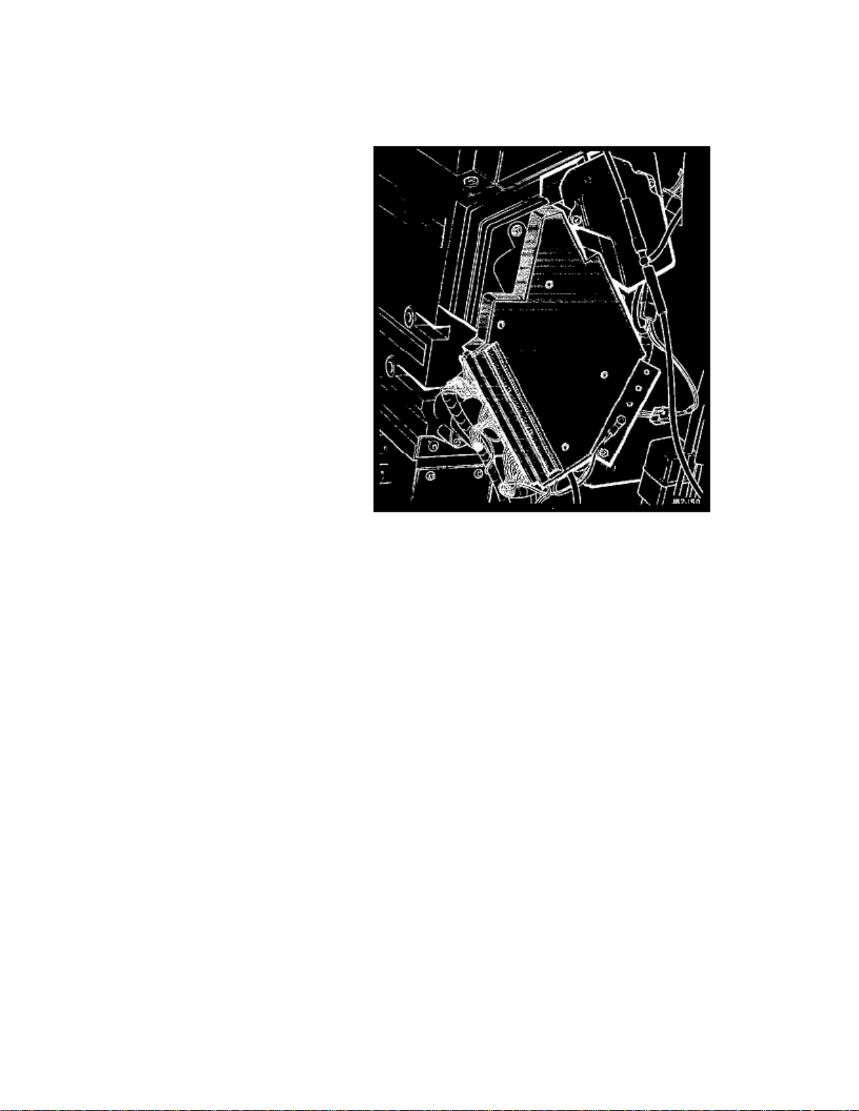
Alarm Module: Locations
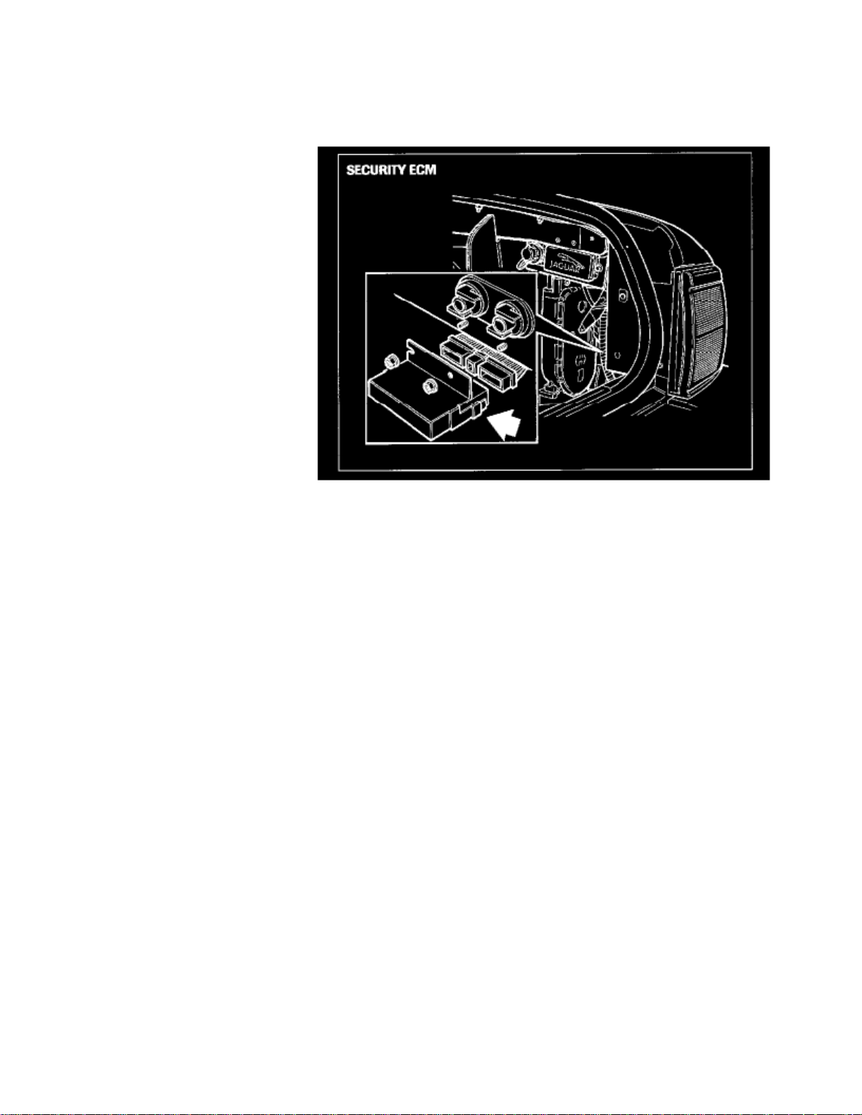
Security system ECM
The ECM is located in the right rear corner of the trunk.
Page 3

Page 4
> Relays and Modules > Relays and Modules - Accessories and Optional Equipment > Alarm Module, (Vehicle Antitheft) > Component Information > Diagrams > Diagram Information and Instructions
Alarm Module: Diagram Information and Instructions
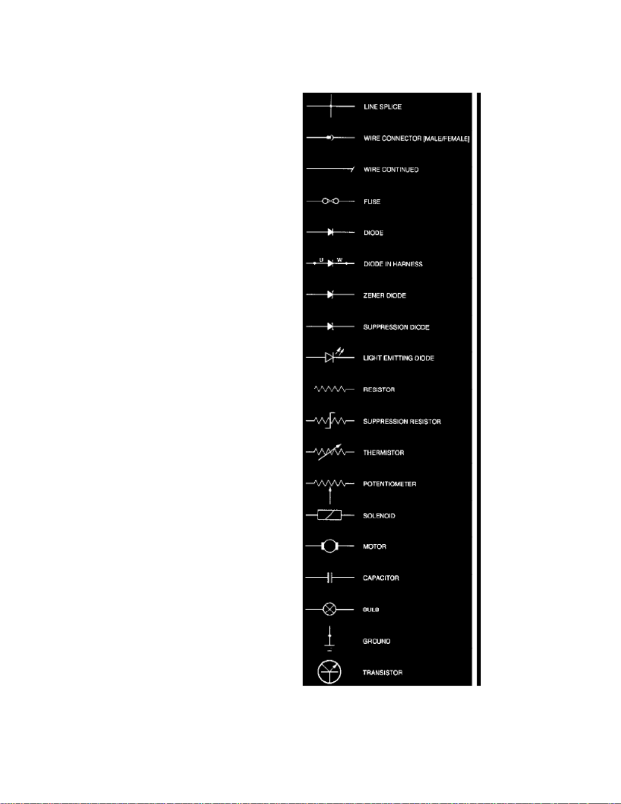
Key To Symbols And Codes
Symbols and Codes
Page 5

> Relays and Modules > Relays and Modules - Accessories and Optional Equipment > Alarm Module, (Vehicle Antitheft) > Component Information > Diagrams > Diagram
Information and Instructions > Page 9
XJ-S Convertible (XJ27) L6-4.0L (1996)
Wiring Color Codes
N Brown
B Black
W White
K Pink
G Green
R Red
Y Yellow
O Orange
S SSate
L Light
Page 6

U Blue
P Purple
When a wire has two or more color code letters, the first letter indicates the main color and the subsequent letter(s) indicate the tracer color(s).
Wiring Harness CodesCode
Description
AB ABS harness
AC Air conditioning harness
BF Boot fuse harness
BL Boot Lid harness
BN Binnacle harness
CC Cruise Control harness
CH Control harness
CS Column switch gear harness
DD Driver's door harness
DS Driver's seat harness
EM Engine Management harness
FP Fuel pump harness
GH Gearbox harness
GL Gearbox link
GS Gear select harness
HH Hood harness (convertible top)
HL High level stop light harness
LB Bulkhead harness (left-hand drive)
LF Left forward harness
LI Lucas injection harness
PD Passenger's door harness
PS Passenger's seat harness
RC Rear courtesy light harness
RF Right forward harness
RH Rearward harness
SB Seat belt harness
SC Security system harness
SH Seat harness
SM Driver's seat control harness
SN Passenger's seat control harness
SS Steering column switch gear harness
ST Starter motor harness
ZA Shorting plug
ZC Shorting plug
ZD Shorting plug
Connector Codes
HARNESS CODE + CONNECTOR NUMBER + PIN NUMBER
EXAMPLE:LB13-24 (Pin Number Is Separated By A Dash)
Note : Absence of a dash and a pin number indicates a single wire connector.
Splice Codes
HARNESS CODE + S + IDENTIFICATION NUMBER
Page 7

> Relays and Modules > Relays and Modules - Accessories and Optional Equipment > Alarm Module, (Vehicle Antitheft) > Component Information > Diagrams > Diagram
Information and Instructions > Page 10
XJ-S Convertible (XJ27) L6-4.0L (1996)
EXAMPLE: LBS3 (No Dash Is Used)
Ground Codes
HARNESS CODE + G + IDENTIFICATION NUMBER
EXAMPLE: LBG78 (No Dash Is Used)
Diode Codes
HARNESS CODE + D + IDENTIFICATION NUMBER
EXAMPLE: LSD3 (No Dash Is Used)
Page 8
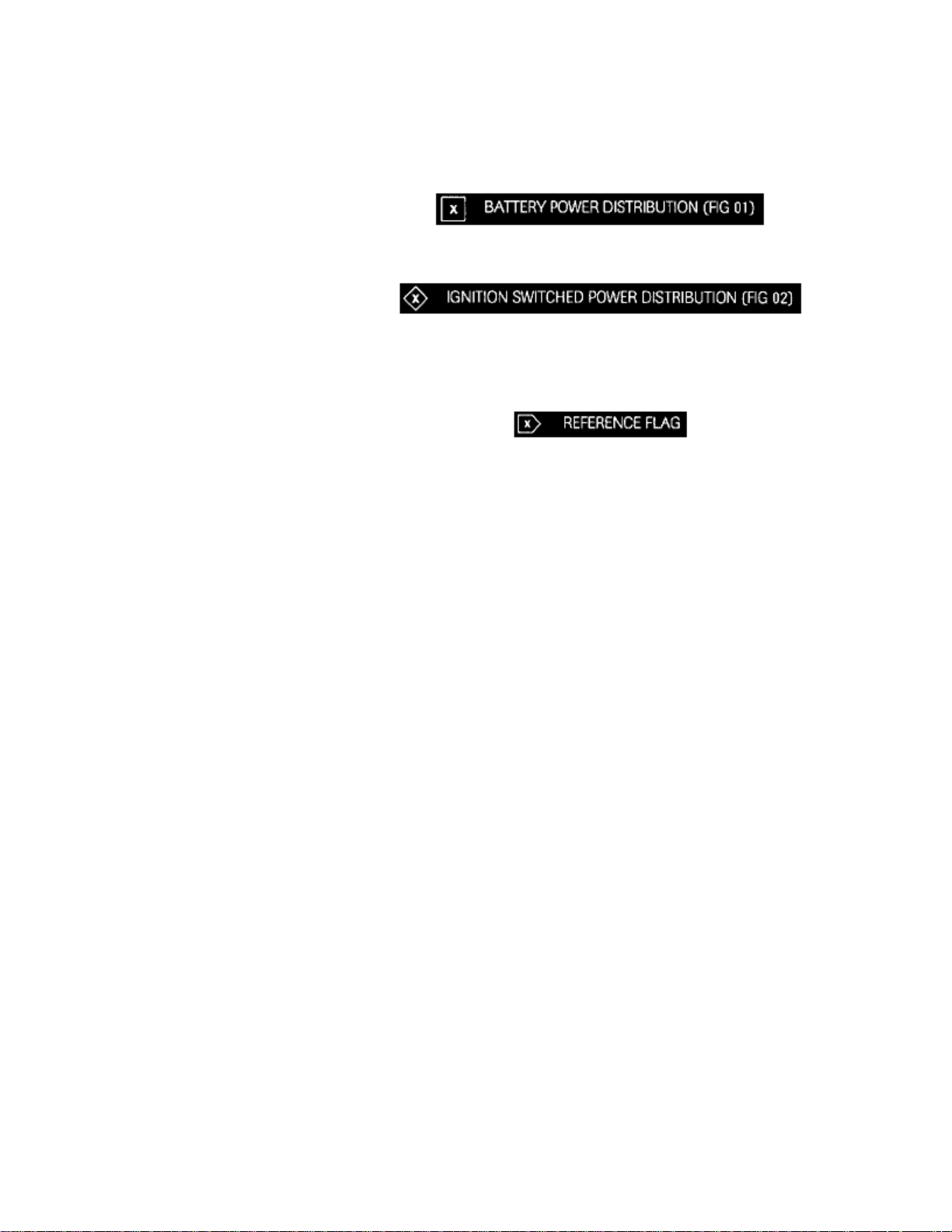
Reference Symbols
Two reference symbols are used to indicate the reminder of the circuit (Feed And Ground) and refer the reader to one of two preliminary figures.
Battery Power Distribution
Ignition Switched Power Distribution
Reference Flags
Reference Flags
This Symbol refers the reader to a figure number only. It does not refer to a flag with the same number on a different figure.
As used in figure 1, 2 and 3, the flag refers to a figure number where the circuit is continued. In this instance, the reader matches the Box orDiamond numbers to trace the circuit.
In most other cases, it is not necessary to refer to another figure for completion of a circuit and circuits which share components. Most of thecircuits where this situation occurs are overlapped to avoid the necessity for cross-referencing to another figure.
Data Pages
Every wiring diagram has a corresponding data page to its left in the book. This information aids the reader in identifying and locatingcomponents, connectors and ground points. Additionally, where applicable, processor and logic unit Input / Output information is provided to aidthe reader in understanding circuit operation. This information should not be used for diagnostic purposes.
Page 9

Page 10

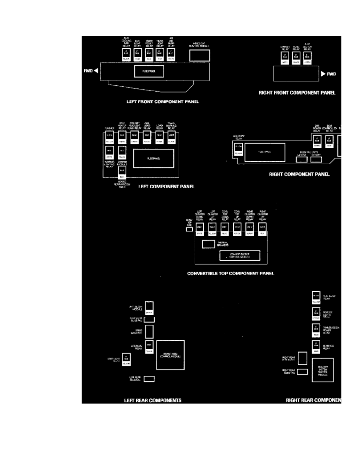
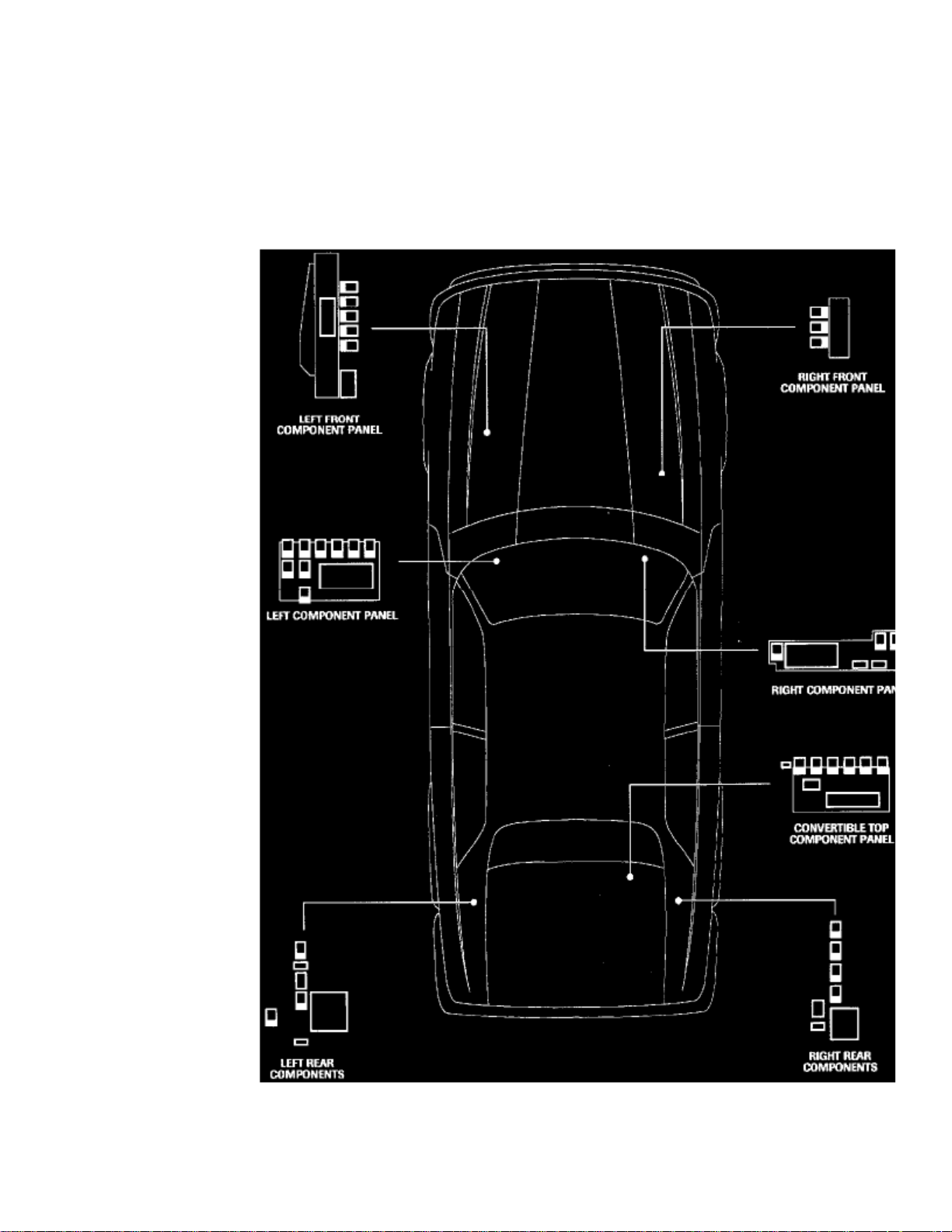
> Relays and Modules > Relays and Modules - Body and Frame > Convertible Top Relay > Component Information > Locations > From VIN 198335
Convertible Top Relay: LocationsFrom VIN 198335
Relay Identification and Location
Component Panel Location
Page 11

> Relays and Modules > Relays and Modules - Body and Frame > Convertible Top Relay > Component Information > Locations > From VIN 198335 > Page 16
XJ-S Convertible (XJ27) L6-4.0L (1996)
Page 12

Relay Identification And Location
Page 13

Page 14

> Relays and Modules > Relays and Modules - Body and Frame > Convertible Top Relay > Component Information > Locations > From VIN 198335 > Page 17
Convertible Top Relay: LocationsUp to VIN 198335
Relay Identification and Location
Component Panel Location
Page 15

> Relays and Modules > Relays and Modules - Body and Frame > Convertible Top Relay > Component Information > Locations > From VIN 198335 > Page 18
XJ-S Convertible (XJ27) L6-4.0L (1996)
Page 16

Relay Identification And Location
Page 17

Page 18

> Relays and Modules > Relays and Modules - Body and Frame > Seat Heater Relay > Component Information > Locations > From VIN 198335
Seat Heater Relay: LocationsFrom VIN 198335
Relay Identification and Location
Component Panel Location
Page 19

> Relays and Modules > Relays and Modules - Body and Frame > Seat Heater Relay > Component Information > Locations > From VIN 198335 > Page 23
XJ-S Convertible (XJ27) L6-4.0L (1996)
Page 20
Relay Identification And Location
Page 21

Page 22

> Relays and Modules > Relays and Modules - Body and Frame > Seat Heater Relay > Component Information > Locations > From VIN 198335 > Page 24
Seat Heater Relay: LocationsUp to VIN 198335
Relay Identification and Location
Component Panel Location
Page 23

> Relays and Modules > Relays and Modules - Body and Frame > Seat Heater Relay > Component Information > Locations > From VIN 198335 > Page 25
XJ-S Convertible (XJ27) L6-4.0L (1996)
Page 24

Relay Identification And Location
Page 25

Page 26

> Relays and Modules > Relays and Modules - Brakes and Traction Control > ABS Main Relay > Component Information > Locations > From VIN 198335
ABS Main Relay: LocationsFrom VIN 198335
Relay Identification and Location
Component Panel Location
Page 27

> Relays and Modules > Relays and Modules - Brakes and Traction Control > ABS Main Relay > Component Information > Locations > From VIN 198335 > Page 31
XJ-S Convertible (XJ27) L6-4.0L (1996)
Page 28

Relay Identification And Location
Page 29

Page 30

> Relays and Modules > Relays and Modules - Brakes and Traction Control > ABS Main Relay > Component Information > Locations > From VIN 198335 > Page 32
ABS Main Relay: LocationsUp to VIN 198335
Relay Identification and Location
Component Panel Location
Page 31

> Relays and Modules > Relays and Modules - Brakes and Traction Control > ABS Main Relay > Component Information > Locations > From VIN 198335 > Page 33
XJ-S Convertible (XJ27) L6-4.0L (1996)
Page 32

Relay Identification And Location
Page 33

Page 34

> Relays and Modules > Relays and Modules - Brakes and Traction Control > ABS / Traction Control Module <--> [Electronic Brake Control Module] > Component Information > Diagrams > Diagram Information and
Instructions
ABS / Traction Control Module: Diagram Information and Instructions
Key To Symbols And Codes
Symbols and Codes
Page 35

> Relays and Modules > Relays and Modules - Brakes and Traction Control > ABS / Traction Control Module <--> [Electronic Brake Control Module] > Component
Information > Diagrams > Diagram Information and Instructions > Page 38
XJ-S Convertible (XJ27) L6-4.0L (1996)
Wiring Color Codes
N Brown
B Black
W White
K Pink
G Green
R Red
Y Yellow
O Orange
S SSate
L Light
Page 36

U Blue
P Purple
When a wire has two or more color code letters, the first letter indicates the main color and the subsequent letter(s) indicate the tracer color(s).
Wiring Harness CodesCode
Description
AB ABS harness
AC Air conditioning harness
BF Boot fuse harness
BL Boot Lid harness
BN Binnacle harness
CC Cruise Control harness
CH Control harness
CS Column switch gear harness
DD Driver's door harness
DS Driver's seat harness
EM Engine Management harness
FP Fuel pump harness
GH Gearbox harness
GL Gearbox link
GS Gear select harness
HH Hood harness (convertible top)
HL High level stop light harness
LB Bulkhead harness (left-hand drive)
LF Left forward harness
LI Lucas injection harness
PD Passenger's door harness
PS Passenger's seat harness
RC Rear courtesy light harness
RF Right forward harness
RH Rearward harness
SB Seat belt harness
SC Security system harness
SH Seat harness
SM Driver's seat control harness
SN Passenger's seat control harness
SS Steering column switch gear harness
ST Starter motor harness
ZA Shorting plug
ZC Shorting plug
ZD Shorting plug
Connector Codes
HARNESS CODE + CONNECTOR NUMBER + PIN NUMBER
EXAMPLE:LB13-24 (Pin Number Is Separated By A Dash)
Note : Absence of a dash and a pin number indicates a single wire connector.
Splice Codes
HARNESS CODE + S + IDENTIFICATION NUMBER
Page 37

> Relays and Modules > Relays and Modules - Brakes and Traction Control > ABS / Traction Control Module <--> [Electronic Brake Control Module] > Component
Information > Diagrams > Diagram Information and Instructions > Page 39
XJ-S Convertible (XJ27) L6-4.0L (1996)
EXAMPLE: LBS3 (No Dash Is Used)
Ground Codes
HARNESS CODE + G + IDENTIFICATION NUMBER
EXAMPLE: LBG78 (No Dash Is Used)
Diode Codes
HARNESS CODE + D + IDENTIFICATION NUMBER
EXAMPLE: LSD3 (No Dash Is Used)
Page 38

Reference Symbols
Two reference symbols are used to indicate the reminder of the circuit (Feed And Ground) and refer the reader to one of two preliminary figures.
Battery Power Distribution
Ignition Switched Power Distribution
Reference Flags
Reference Flags
This Symbol refers the reader to a figure number only. It does not refer to a flag with the same number on a different figure.
As used in figure 1, 2 and 3, the flag refers to a figure number where the circuit is continued. In this instance, the reader matches the Box orDiamond numbers to trace the circuit.
In most other cases, it is not necessary to refer to another figure for completion of a circuit and circuits which share components. Most of thecircuits where this situation occurs are overlapped to avoid the necessity for cross-referencing to another figure.
Data Pages
Every wiring diagram has a corresponding data page to its left in the book. This information aids the reader in identifying and locatingcomponents, connectors and ground points. Additionally, where applicable, processor and logic unit Input / Output information is provided to aidthe reader in understanding circuit operation. This information should not be used for diagnostic purposes.
Page 39

Page 40
> Relays and Modules > Relays and Modules - Brakes and Traction Control > ABS / Traction Control Module <--> [Electronic Brake Control Module] > Component Information > Diagrams > Page 40
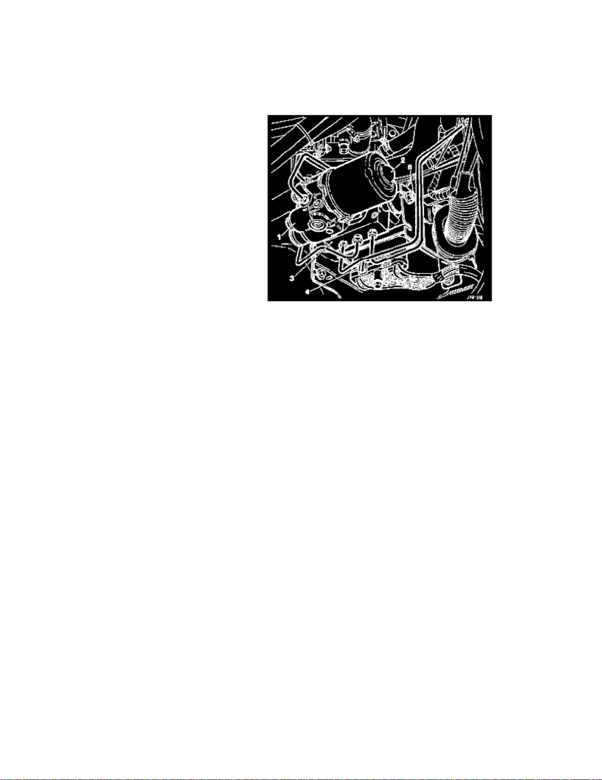
ABS / Traction Control Module: Description and Operation
ABS control module
4 3
The control module (CM) (), located beneath the modulator valve block (), is the system controller and processes all the information supplied fromthe external sensors and probes. Refer to the Control Module Connection Diagram. The signals from the four wheel speed sensors are independentlyprocessed by the CM, calculating numerical values which correspond directly to the wheel speed. These values are converted into control signals forpressure modulation during ABS control.
The CM continuously monitors ABS operation, lighting the ABS warning indicator and inhibiting or disabling the system when faults are detected. Ina fault condition, conventional braking is unaffected. The CM is self testing and cannot be fault diagnosed beyond 'black box' level, i.e. a faultymodule. The CM houses the solenoids which operate the inlet and outlet valves of the modulator valve block. There is no electrical connectionbetween the CM and the modulator valve block, but there is an electrical connection from the CM to the pump motor.
The CM functions include the following:
1. Providing control signals for the operation of ABS solenoid valves2. Calculating wheel speed from voltage signals transmitted by the wheel speed sensors3. Monitoring of all electrical components4. On Board Diagnostics (OBD}: storage of fault codes in a non-volatile memory.
The fault codes generated by the CM are stored in a non-volatile memory which can be read via the OBD link. The ABS warning indicator is lit if theCM connector is loose or not fitted.
Page 41

> Relays and Modules > Relays and Modules - Brakes and Traction Control > ABS / Traction Control Module <--> [Electronic Brake Control Module] > Component
Information > Diagrams > Page 41
XJ-S Convertible (XJ27) L6-4.0L (1996)
Page 42
Control Module Connection Diagram
Control module connections
Control module connections, numbered 1 to 28, provide the necessary input/output signals to enable the module to control and monitor ABSoperation.
Connections are as follows:
Page 43

> Relays and Modules > Relays and Modules - Brakes and Traction Control > ABS / Traction Control Module <--> [Electronic Brake Control Module] > Component
Information > Diagrams > Page 42
XJ-S Convertible (XJ27) L6-4.0L (1996)
Page 44

Page 45

Page 46

> Relays and Modules > Relays and Modules - Brakes and Traction Control > Hydraulic Brake Booster Pump Relay > Component Information > Locations > From VIN 198335
Hydraulic Brake Booster Pump Relay: LocationsFrom VIN 198335
Relay Identification and Location
Component Panel Location
Page 47

> Relays and Modules > Relays and Modules - Brakes and Traction Control > Hydraulic Brake Booster Pump Relay > Component Information > Locations > From VIN
198335 > Page 47
XJ-S Convertible (XJ27) L6-4.0L (1996)
Page 48

Relay Identification And Location
Page 49

Page 50

> Relays and Modules > Relays and Modules - Brakes and Traction Control > Hydraulic Brake Booster Pump Relay > Component Information > Locations > From VIN 198335 > Page 48
Hydraulic Brake Booster Pump Relay: LocationsUp to VIN 198335
Relay Identification and Location
Component Panel Location
Page 51

> Relays and Modules > Relays and Modules - Brakes and Traction Control > Hydraulic Brake Booster Pump Relay > Component Information > Locations > From VIN
198335 > Page 49
XJ-S Convertible (XJ27) L6-4.0L (1996)
Page 52

Relay Identification And Location
Page 53

Page 54

> Relays and Modules > Relays and Modules - Cooling System > Auxiliary Water Pump Relay > Component Information > Locations > From VIN 198335
Auxiliary Water Pump Relay: LocationsFrom VIN 198335
Relay Identification and Location
Component Panel Location
Page 55

> Relays and Modules > Relays and Modules - Cooling System > Auxiliary Water Pump Relay > Component Information > Locations > From VIN 198335 > Page 55
XJ-S Convertible (XJ27) L6-4.0L (1996)
Page 56

Relay Identification And Location
Page 57

Page 58

> Relays and Modules > Relays and Modules - Cooling System > Auxiliary Water Pump Relay > Component Information > Locations > From VIN 198335 > Page 56
Auxiliary Water Pump Relay: LocationsUp to VIN 198335
Relay Identification and Location
Component Panel Location
Page 59

> Relays and Modules > Relays and Modules - Cooling System > Auxiliary Water Pump Relay > Component Information > Locations > From VIN 198335 > Page 57
XJ-S Convertible (XJ27) L6-4.0L (1996)
Page 60

Relay Identification And Location
Page 61

Page 62
> Relays and Modules > Relays and Modules - Cruise Control > Cruise Control Module > Component Information > Description and Operation
Cruise Control Module: Description and Operation
(SCCM)
The Speed Control Control Module , located behind the fascia, adjacent to the steering column, provides system control and an interface toexternal input signals from the instrument pack, gear selector module, traction control system, control switches, and foot pedal switches. The set speedvalue is retained in SCCM memory and continuously compared to actual vehicle speed. Adjustments are made, as necessary, to maintain set speed bycontrol of the vacuum pump and control valve.
Speed Control System Component Locations, Fig.1
1. Speed control switches2. Throttle linkage and bellows3. Vacuum dump valve4. Vacuum pump and control valve unit5. Speed control control module (SCCM)6. Brake switches7. Clutch switch (where installed)
Page 63

Page 64

> Relays and Modules > Relays and Modules - Cruise Control > Cruise Control Module > Component Information > Description and Operation > Page 62
Cruise Control Module: Service and Repair
SPEED CONTROL ECU
- Reposition the passenger footwell carpet for access to the ECU panel securing screws.
- Undo and remove the floor panel screws.
- Displace the panel and disconnect the ECU harness multi-plug.
- Release the retaining clip and displace and remove the unit.
- Align the new ECU, secure with retaining clip and connect the harness multi-plug.
- Reposition and secure the panel, reposition carpet.
Page 65

Page 66

> Relays and Modules > Relays and Modules - Cruise Control > Cruise Control Relay > Component Information > Description and Operation
Cruise Control Relay: Description and Operation
A relay to inhibit system operation in all transmission positions other than D, 2 and 3.
Page 67

Page 68
> Relays and Modules > Relays and Modules - HVAC > Auxiliary Water Pump Relay > Component Information > Locations > From VIN 198335
Auxiliary Water Pump Relay: LocationsFrom VIN 198335
Relay Identification and Location
Component Panel Location
Page 69

> Relays and Modules > Relays and Modules - HVAC > Auxiliary Water Pump Relay > Component Information > Locations > From VIN 198335 > Page 71
XJ-S Convertible (XJ27) L6-4.0L (1996)
Page 70

Relay Identification And Location
Page 71

Page 72

> Relays and Modules > Relays and Modules - HVAC > Auxiliary Water Pump Relay > Component Information > Locations > From VIN 198335 > Page 72
Auxiliary Water Pump Relay: LocationsUp to VIN 198335
Relay Identification and Location
Component Panel Location
Page 73

> Relays and Modules > Relays and Modules - HVAC > Auxiliary Water Pump Relay > Component Information > Locations > From VIN 198335 > Page 73
XJ-S Convertible (XJ27) L6-4.0L (1996)
Page 74

Relay Identification And Location
Page 75

Page 76

> Relays and Modules > Relays and Modules - HVAC > Compressor Clutch Relay > Component Information > Locations > From VIN 198335
Compressor Clutch Relay: LocationsFrom VIN 198335
Relay Identification and Location
Component Panel Location
Page 77

> Relays and Modules > Relays and Modules - HVAC > Compressor Clutch Relay > Component Information > Locations > From VIN 198335 > Page 78
XJ-S Convertible (XJ27) L6-4.0L (1996)
Page 78

Relay Identification And Location
Page 79

Page 80

> Relays and Modules > Relays and Modules - HVAC > Compressor Clutch Relay > Component Information > Locations > From VIN 198335 > Page 79
Compressor Clutch Relay: LocationsUp to VIN 198335
Relay Identification and Location
Component Panel Location
Page 81

> Relays and Modules > Relays and Modules - HVAC > Compressor Clutch Relay > Component Information > Locations > From VIN 198335 > Page 80
XJ-S Convertible (XJ27) L6-4.0L (1996)
Page 82

Relay Identification And Location
Page 83

Page 84
> Relays and Modules > Relays and Modules - HVAC > Control Module HVAC > Component Information > Locations
Control Module HVAC: Locations
Air Conditioning Control Module
Mounted to side of A/C unit.
Page 85

Page 86

> Relays and Modules > Relays and Modules - Lighting and Horns > Backup Lamp Relay > Component Information > Locations > From VIN 198335
Backup Lamp Relay: LocationsFrom VIN 198335
Relay Identification and Location
Component Panel Location
Page 87

> Relays and Modules > Relays and Modules - Lighting and Horns > Backup Lamp Relay > Component Information > Locations > From VIN 198335 > Page 89
XJ-S Convertible (XJ27) L6-4.0L (1996)
Page 88

Relay Identification And Location
Page 89

Page 90

> Relays and Modules > Relays and Modules - Lighting and Horns > Backup Lamp Relay > Component Information > Locations > From VIN 198335 > Page 90
Backup Lamp Relay: LocationsUp to VIN 198335
Relay Identification and Location
Component Panel Location
Page 91

> Relays and Modules > Relays and Modules - Lighting and Horns > Backup Lamp Relay > Component Information > Locations > From VIN 198335 > Page 91
XJ-S Convertible (XJ27) L6-4.0L (1996)
Page 92

Relay Identification And Location
Page 93

Page 94

> Relays and Modules > Relays and Modules - Lighting and Horns > Brake Lamp Relay > Component Information > Locations > From VIN 198335
Brake Lamp Relay: LocationsFrom VIN 198335
Relay Identification and Location
Component Panel Location
Page 95

> Relays and Modules > Relays and Modules - Lighting and Horns > Brake Lamp Relay > Component Information > Locations > From VIN 198335 > Page 96
XJ-S Convertible (XJ27) L6-4.0L (1996)
Page 96

Relay Identification And Location
Page 97

Page 98
> Relays and Modules > Relays and Modules - Lighting and Horns > Brake Lamp Relay > Component Information > Locations > From VIN 198335 > Page 97
Brake Lamp Relay: LocationsUp to VIN 198335
Relay Identification and Location
Component Panel Location
Page 99

> Relays and Modules > Relays and Modules - Lighting and Horns > Brake Lamp Relay > Component Information > Locations > From VIN 198335 > Page 98
XJ-S Convertible (XJ27) L6-4.0L (1996)
Page 100

Relay Identification And Location
 Loading...