

Page 1

Vehicle Care Handbook
Foreword
JAGUAR CARS LIMITED,
dedicated to the design and production of vehicles which meet
the expectations of the world's most discerning purchasers.
To complement the features, systems and technology of your
new vehicle we have produced this Vehicle Care Handbook. In
it we have undertaken to provide information on vehicle care
and maintenance to enable you to obtain lasting pleasure and
reliability from your vehicle.
The information contained herein applies to a range of vehicles
and not to a specific vehicle. For the specification of a particular
vehicle, owners should consult their Jaguar Dealer.
Published July 1999 by Parts and Service Communications Jaguar Cars Limited Publication Part No. JJM 18 16 12/00
as manufacturers, are
The Manufacturer reserves the right to vary its specifications
with or without notice, and at such times and in such manner as
it thinks fit. Major as well as minor changes may be involved in
accordance with the Manufacturer's policy of constant product
improvement.
All rights reserved. No part of this publication may be
reproduced, stored in a retrieval system or transmitted, in any
form, electronic, mechanical, photocopying, recording or other
means without prior written permission from the Service
Division of Jaguar Cars Limited.
Page 2

Contents
1. Introduction
General Information . . . . . . . . . . . . . . . . . . . . . . . .1-1
Safety Warning and Caution Labels . . . . . . . . . . . . .1 -5
General Precautions . . . . . . . . . . . . . . . . . . . . . . . .1 -6
Hood Release Control . . . . . . . . . . . . . . . . . . . . . . .1 - 8
2. Cleaning
Introduction . . . . . . . . . . . . . . . . . . . . . . . . . . . . . .2 -1
Exterior Care . . . . . . . . . . . . . . . . . . . . . . . . . . . . . .2 -1
Interior Care . . . . . . . . . . . . . . . . . . . . . . . . . . . . . .2-3
3. Routine checks
Introduction . . . . . . . . . . . . . . . . . . . . . . . . . . . . . .3 -1
Regular Checks . . . . . . . . . . . . . . . . . . . . . . . . . . . .3 - 1
Reservoir and Dipstick Locations . . . . . . . . . . . . . . .3 - 2
Cooling System . . . . . . . . . . . . . . . . . . . . . . . . . . . .3-8
Recommended Engine Oil . . . . . . . . . . . . . . . . . . . .3 -9
Capacities . . . . . . . . . . . . . . . . . . . . . . . . . . . . . . . .3 - 10
4. Roadside emergency service
Introduction . . . . . . . . . . . . . . . . . . . . . . . . . . . . . . 4 -1
Spare Wheel and Jacking Equipment . . . . . . . . . . . .4-1
Wheel Changing and Jacking . . . . . . . . . . . . . . . . . .4-2
Loosening the Wheel Nuts. . . . . . . . . . . . . . . . . . . . 4 -2
Emergency Starting . . . . . . . . . . . . . . . . . . . . . . . . .4- 8
Vehicle Recovery . . . . . . . . . . . . . . . . . . . . . . . . . . .4 - 10
Fuses and Fuse Boxes . . . . . . . . . . . . . . . . . . . . . . . 4 -12
Fuse Ratings . . . . . . . . . . . . . . . . . . . . . . . . . . . . . . 4- 16
Control Modules – Identification and Location . . . .4-21
Relay Identification and Location. . . . . . . . . . . . . . .4-22
5. Vehicle maintenance
Introduction . . . . . . . . . . . . . . . . . . . . . . . . . . . . . . 5 -1
Regular Servicing . . . . . . . . . . . . . . . . . . . . . . . . . . . 5 - 1
Tyres . . . . . . . . . . . . . . . . . . . . . . . . . . . . . . . . . . . .5 - 1
Battery . . . . . . . . . . . . . . . . . . . . . . . . . . . . . . . . . .5- 6
Generator (GEN) . . . . . . . . . . . . . . . . . . . . . . . . . . .5 - 6
Bulb Renewal . . . . . . . . . . . . . . . . . . . . . . . . . . . . . 5 -9
Bulb Chart . . . . . . . . . . . . . . . . . . . . . . . . . . . . . . . . 5- 18
Windscreen Wiper Blade . . . . . . . . . . . . . . . . . . . . .5-19
Windscreen Washers. . . . . . . . . . . . . . . . . . . . . . . .5-19
Page 3

6. Specifications
Weights (Average/Approximate) . . . . . . . . . . . . . . . 6- 2
Dimensions. . . . . . . . . . . . . . . . . . . . . . . . . . . . . . . 6- 5
Fuel Requirements . . . . . . . . . . . . . . . . . . . . . . . . . 6-11
7. Accessories
Electrical Accessories . . . . . . . . . . . . . . . . . . . . . . . 7-1
Electrical Accessory Supply Sockets . . . . . . . . . . . . 7-1
Earth Points . . . . . . . . . . . . . . . . . . . . . . . . . . . . . . 7-1
A comprehensive index is located at the back of this book.
Contents
Page 4

Contents
Page 5

1 Introduction
Introduction 1-1
General Information
When left-hand or right-hand is used in
the text, this refers to the left-hand side
or right-hand side of the vehicle, viewed
from the rear.
Jaguar Dealers
Jaguar Dealers are chosen with care. Each
is dedicated to providing a Sales, Service
and Genuine Jaguar Parts facility of the
highest standard.
Jaguar Dealers provide full technical
back-up from the factory with
comprehensive training for all their
technicians. All Dealers’ workshops
operate to the highest standard and have
all the necessary approved tools and
equipment essential to maintain or repair
Jaguar vehicles.
The Jaguar Diagnostic System
Many of the vehicle systems are
controlled by complex electronic devices.
The equipment used to assist diagnosis of
faults in the electrical and electronic
systems of the vehicle is unique and is
only available to Jaguar Dealers. Use of
this equipment will enable the Dealer to
trace and rectify faults in the system and
ensure that only faulty components are
repaired or replaced.
Caution: Severe damage to the
electrical system and electronic
components can occur if any attempt
is made to diagnose faults in the
electrical system using conventional
diagnostic equipment (for example,
the use of test lamps, low impedance
voltmeters, etc.).
Regular Servicing
Each vehicle is given a full ‘Pre-Delivery
Inspection’ to ensure that all systems
function correctly and the vehicle meets
its specification.
Regular maintenance and servicing is the
responsibility of the owner. Jaguar
Dealers will be pleased to arrange
periodic servicing in accordance with the
USA/Mexico ‘
Booklet or Canadian ‘
Warranty and Benefits Information
Booklet.
USA and Mexico
arrange appointments on a mileage or
time interval basis to ensure that all
routine and corrective maintenance work
is undertaken and recorded in the
‘
Passport to Service
Canada
appointments on a distance or time
interval basis to ensure that all routine
and corrective maintenence work is
undertken and recorded in the ‘
Jaguar
Failure to implement maintenance at the
recommended intervals could result in
deterioration of vehicle performance and
possible infringement of regulations.
Passport to Service
Club Jaguar
: Jaguar Dealers will
’ Booklet.
: Jaguar Dealers will arrange
’ Warranty and Benefits Booklet.
’
’
Club
Page 6

1-2 Introduction
Maintenance Summary
It is the owner’s responsibility to ensure that the vehicle is
maintained in accordance with the Maintenance Schedules.
Repairs resulting from a failure to maintain are not covered by
the warranty.
The USA/Mexico ‘
‘
Club Jaguar
convenient document to record all maintenance services on the
vehicle.
All vehicle literature should be passed to any subsequent owner
at the time of resale.
USA and Mexico
available, a replacement may be obtained by writing to the
Consumer Relations Department, Jaguar Cars, 555 MacArthur
Boulevard, Mahwah, New Jersey 07430, quoting the vehicle
identification number from the plate located inside the
windscreen, plus the date of purchase and current mileage or
kilometres.
Canada
Information Booklet is not available, a replacement may be
obtained by writing to the consumer Relations Department,
Jaguar Canada, 8 Indel Lane, Bramalea, Ontario, L6T 4H3,
quoting the vehicle identification number from the plate located
inside the windscreen, plus the date of purchase and current
kilometres.
: If the ‘
Passport to Service
’ Warranty and Benefits information Booklet is a
: If the ‘
Club Jaguar
Passport to Service
’ Warranty and Benefits
’ Booklet or Canadian
’ Booklet is not
Scheduled Maintenance
The Maintenance Schedules list all the maintenance operations
and their intervals. Because of the need for the use of
specialized equipment and skills, it is strongly recommended
that all service work be entrusted to a Jaguar Dealer.
Should the vehicle cover a low annual mileage, have a high
proportion of short journeys or operate in severe conditions,
Jaguar Cars recommend that the lubrication service shown in
the maintenance schedule in the ‘
be performed at intervals not to exceed six months.
The Maintenance Schedules may be revised from time to time.
Jaguar Dealers will be notified of revisions by Service Policy
Letters or Technical Bulletins.
USA only
control devices and system may be performed by any
automotive repair establishment or individual using any
automotive part which has be certified by Jaguar Cars.
: Maintenance, replacement or repair of the emission
Passport to Service
’ Booklet
Page 7
Safety Precautions
Take particular note of
throughout this handbook.
!
WARNING:
Warnings are procedures which must be followed
precisely to help avoid the risk of personal injury.
Caution: Cautions are procedures which must be
followed precisely to reduce the possibility of damage to
the vehicle and resultant risk of personal injury or
inconvenience.
Warning symbols on the vehicle
On encountering the warning triangle and open book symbol on
the vehicle, it is important that you consult the relevant section
of this handbook before touching this part of the vehicle or
attempting adjustments of any kind.
WARNINGS
and
Cautions
given
Introduction 1-3
JLX-208
Page 8

1-4 Introduction
Safety Precautions
!
WARNING:
1. Many liquids and other substances used in vehicles are
poisonous and must never be consumed and should
be kept away from open wounds. These substances
include anti-freeze, brake fluid, fuel, windscreen
washer additives, lubricants and various adhesives.
2. The presence of any unusual fumes (e.g. petrol or
exhaust fumes) in the passenger compartment and/or
luggage compartment should be corrected
immediately by a Jaguar Dealer. If you must drive
under these conditions do so only with all windows
fully open.
3. Any modifications to the fuel system not specifically
designed for this Jaguar are prohibited. Such
modifications in some circumstances could result in a
fire. All service actions must be entrusted to a
Jaguar Dealer.
4. Alterations to the electrical system, including the
fitting of accessories not designed for this Jaguar may
cause damage to the electrical circuits and systems. In
some circumstances this could result in a fire. All
accessory work should be entrusted to a Jaguar Dealer.
5. No attempt should be made to repair a fuse that has
blown. Always install a fuse of the correct amperage
(see the fuse charts on pages 4-17 to 4-21). Failure to
comply with the above may cause a fire hazard or
serious damage elsewhere in the electrical circuit.
(continued)
6. Avoid contact with battery acid which is poisonous
and corrosive. Acid will cause burns to the skin as well
as to the eyes. In the event of skin or eye
contamination, wash the affected area with water
thoroughly. Seek immediate medical attention when
eye contact has occurred.
7. Never reverse the battery terminal connections.
Always disconnect both terminals before battery
charging.
8. When disconnecting the battery connections, always
disconnect the earth terminal first and reconnect last.
9. Batteries produce combustible gas (hydrogen) when
charging. Switch off the charger before connecting or
disconnecting terminal connections to avoid sparks
and short circuits.
10.Do not disconnect any pipes in the air conditioning
refrigeration system. A refrigerant is used which can
cause blindness if allowed to contact the eyes.
FIRST AID: If refrigerant should contact the eyes or
skin, wash the eyes or affected area with cold water for
several minutes. Do not rub. As soon as possible
thereafter, obtain treatment from a doctor or eye
specialist.
Page 9
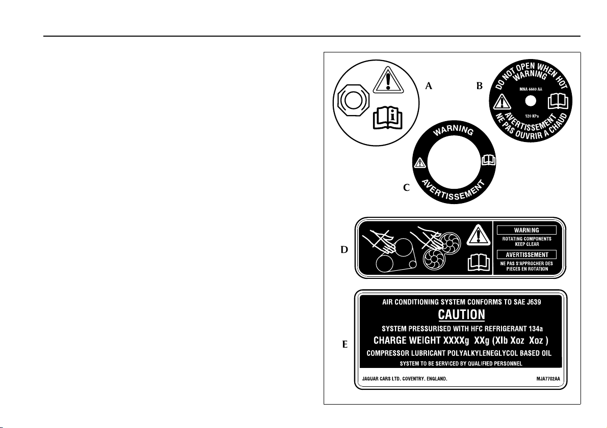
Safety Warning and Caution Labels
Do not remove any warning labels from the hood or
Note:
inside of the vehicle.
Braking System (A)
The brake fluid caution symbol is moulded into the master
cylinder filler cap.
Brake system warning information is moulded into the master
cylinder reservoir and states:
WARNING – CLEAN FILLER CAP BEFORE REMOVING. USE
ONLY SUPER DOT 4 BRAKE FLUID FROM A SEALED
CONTAINER.
Refer to SECTION 3 for topping up the power steering system.
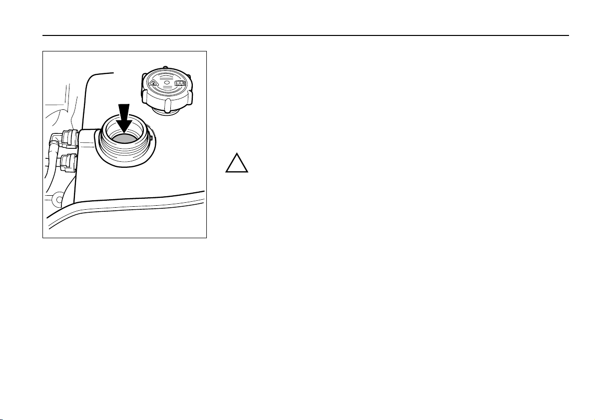
Cooling System (B)
The header tank label is located on the filler cap and states:
WARNING – DO NOT OPEN WHEN HOT.
Power Steering System (C)
The label is located on the reservoir filler cap and states:
WARNING.
Rotating Components (D)
A label is located on the fan shroud and states:
WARNING – ROTATING COMPONENTS – KEEP CLEAR.
Climate Control System (E)
The label located under the hood on the left-hand side states:
CAUTION – System pressurised with HFC refrigerant 134a.
System to be serviced by qualified personnel.
Introduction 1-5
+
-
+
-
JLK-061
Page 10

1-6 Introduction
General Precautions
• Ensure that the vehicle is securely supported before working
underneath it.
handbrake.
• Whenever possible use a suitable wheel-free lift when
working beneath the vehicle.
If a jack is used to support the vehicle, use axle stands
carefully placed at the jacking points to provide a rigid
support.
Do not
member.
• Ensure that adequate ventilation is provided when volatile
degreasing agents are being used.
•
• Wear protective overalls, ensure loose clothing (ties, etc.) are
• Do not leave opened containers of oil, fuel, etc., about the
• Do not leave tools, equipment, spilt oil, etc., around or on
• Place a fire extinguisher close to the vehicle and disconnect
use volatile cleaning fluids under a vehicle standing
Never
over a pit. Many such fluids give off vapours which are
heavier than air and dangerous to inhale.
removed or covered when working adjacent to moving
components (fan belts, etc.).
work area. Always refit caps/seals to partially used
containers when storing them for later use.
the work area.
the negative battery terminal. Do not use a naked flame to
provide illumination, especially under the vehicle, or in the
engine and luggage compartments. Do not smoke while
working on the vehicle.
Chock a front wheel and apply the
use any jacking equipment under the front cross
• Do not apply heat in an attempt to free nuts or fittings. This
will damage protective coatings and there is a risk of damage
to electronic equipment and brake and fuel lines from
conducted heat.
• Inspect power leads of any mains electrical equipment for
damage, and check that it is properly earthed.
General Precautions Against Damage
• When working in the engine compartment protect the
exterior paintwork by using suitable covers over the wings
and scuttle.
• To prevent soiling the interior, carry out jobs requiring
access to the passenger or luggage compartments first. If a
job involves access to the interior in the course of other
work, prevent the transfer of oil and grease to the interior by
using seat and carpet covers and wearing clean overalls and
gloves.
• Always use a recommended service tool, where specified.
• Avoid spilling hydraulic fluid or battery acid on paintwork.
Wash off with water immediately if this occurs.
Page 11

Introduction 1-7
General Precautions
Used Engine Oil
!
WARNING:
Prolonged and repeated contact may cause serious skin
disorders, including dermatitis and cancer.
Always use a hand cream to protect the skin from oil
contamination. Avoid contact with the skin as far as possible
and wash thoroughly after any contact. Keep oils out of reach of
children.
PROTECT THE ENVIRONMENT:
water courses and soil. Use authorised waste collection
facilities, including civic amenity sites and garages providing
facilities for the disposal of used oil, oil filters and batteries. If in
doubt, contact your Local Authority for advice on disposal.
Engine and Throttle Settings
Do not attempt to make adjustments to the engine or throttle
settings. Many vehicle systems are controlled by complex
electronic devices and require specialist knowledge. Such work
should be entrusted to a Jaguar Dealer.
Battery/Ignition Isolator Switches
Non-approved battery isolator switches, which disconnect the
power supply to all electrical circuits, are
(continued)
It is illegal to pollute drains,
recommended.
not
Hydraulic Fluid
The Brake Hydraulic Fluid in the master cylinder and brake
operating system uses non-mineral polyglycol based brake fluid
with a minimum standard of JAGUAR SUPER DOT 4. ONLY
FLUID OF THIS TYPE AND STANDARD MAY BE USED.
!
WARNING:
Contamination of the brake system fluid by as little as
1 per cent will cause rapid deterioration of the system
seals. Ensure that the brake fluid reservoir cap is securely
fitted.
Electrical Accessories
The fitting of any electrical accessory
to a Jaguar Dealer. Refer to
SECTION 7. This information must be observed before fitting
any accessories.
Electrical Accessories
should only
be entrusted
in
Page 12
1-8 Introduction
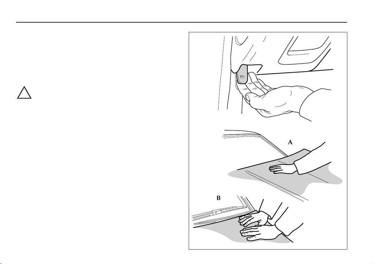
Hood Release Control
The hood lock release control is below the fascia on the driver’s
side of the vehicle.
To op en:
across to the centre of the hood and lift the rear edge. The gas
filled struts will assist raising the hood, and retain it in the fully
open position.
Before closing the hood ensure that no one is obstructing
the closing area and that hands and clothes are clear.
Remove tools, cleaning cloths, etc. from the engine
compartment.
Hood latching:
12 inches (250 to 300 mm) of the fully closed position. Place the
left hand on the hood as shown at (A). Then pressing
downwards slam the hood shut. This action should engage both
the right-hand and left-hand latches.
Should one latch fail to engage, place both hands, as shown
at (B), above the unlatched side and press down firmly on the
hood until it engages.
Release the hood lock by pulling the lever. Reach
!
WARNING:
Close the hood to within a distance of 10 to
JLX-149
Page 13

2Cleaning
Cleaning 2-1
Introduction
This section gives full details of the methods and cleaning agents
which should be used to achieve the best results and maintain
the finish of the vehicle, both internally and externally.
Read carefully the restrictions on the use of jet washes and
automatic car washes.
Exterior Care
Valet Kit
A valet kit containing a selection of Car Care products is
available from the Jaguar accessory range.
All the cleaning materials mentioned in this section are
Note:
available from the Jaguar Accessory Range.
Washing
For best results, do not wash the vehicle under strong sunlight.
Always allow the vehicle to cool down before washing.
Do not use a dry cloth to wipe dirty paintwork. Dust and gritty
substances are abrasive and will scratch the paintwork. Remove
dirt using a cellulose sponge and plenty of warm (never hot)
water. Rinse off with clean water and dry using a clean, damp
chamois leather.
Do not use household soaps or detergents. The use of Jaguar
Vehicle Shampoo is recommended.
Do not direct hoses at full force around door and luggage
compartment seals. Using high pressure water jets on the
paintwork is not recommended.
Do not allow bird droppings or tree sap to harden. Remove from
paintwork immediately with a lukewarm soap and water
solution.
In winter, when salt is used on the roads, wash the vehicle
frequently, and immediately after encountering such conditions.
Clean undersides and wheel arches using a high pressure jet.
Automatic Car Wash
Regular use of automatic car washes tends to dull the
Note:
lustre of the paintwork.
Before entering the car wash it is essential to:
Switch off the radio to retract the aerial,
Remove wing mounted telephone antennas,
Fold down screen mounted telephone antennas,
Fold in door mounted rear view mirrors.
If your vehicle is fitted with a Jaguar approved cellular
Note:
telephone, you are advised to switch the telephone and the
ignition OFF.
After leaving the car wash, switch on the windscreen wiper
immediately to remove water and prevent a build up of wax.
Jaguar Screen Clean Paste can be used to clean any residual wax
from the glass.
Removing Grease and Tar
Remove grease or tar with Jaguar Tar Remover or methylated
spirit (alcohol). White spirit is also effective, but must not be
applied to rubber, particularly the windscreen wiper blade.
Page 14

2-2 Cleaning
Exterior Care
Alloy Road Wheels
Alloy wheels have an anti-corrosion protective coating, which
should not be damaged.
Wash the wheels at two week intervals to avoid an accumulation
of particles which could become embedded in the wheel
surface.
An Alloy Wheel Clean Kit is included in the Jaguar accessory
range.
In salty conditions the wheels should be cleaned weekly.
Chromium-plated Alloy Road Wheels
It is recommended that chromium-plated alloy road wheels are
cleaned using Jaguar Vehicle Shampoo and Chrome Polish.
Caution: Do NOT use proprietary wheel cleaners.
Glass Surfaces
To avoid scratching glass surfaces,
paper or cloth. Use clean, warm water and a chamois
dry
leather which is reserved for glass only.
The following products will ensure glass surfaces and
windscreen wipers are kept in good condition:
Jaguar Screen Clean Paste
windscreen
windscreen wiper.
Jaguar Glass Cleaner
surfaces.
(continued)
do not
– Apply to the exterior of the
to ensure effective operation of the
only
– Interior and exterior of all other
clean dirty glass with
Jaguar Screen Wash
Jaguar Winter Care Kit comprising de-icer, ice scraper,
anti-mist wipe cloth and aerial cleaner
weather conditions.
Note:
Renew the wiper blade when worn to prevent scratching.
1.
Clean regularly with a mild detergent solution.
It is advisable to clean the windscreen with Jaguar Screen
2.
Clean Paste at regular intervals.
Polishing Paintwork and Chromium Plating
For maximum protection against road dust, salts, industrial
fallout etc., it is recommended that the vehicle is polished
regularly using Jaguar Polish, Chrome Polish and a Polishing
Cloth.
– Washer reservoir additive.
– for use in adverse
Page 15

Cleaning 2-3
Exterior Care
Underbonnet cleaning
Underbonnet cleaning using high pressure hoses or steam
cleaners should be done by a Jaguar Dealer. Indiscriminate use
of cleaning equipment could damage or contaminate the
electronic control modules and fuse boxes.
Aerial Care
Regular cleaning with a special aerial cleaner, will ensure
smooth and reliable operation of the aerial.
Always wipe the aerial in an upwards direction.
Lubricate using an aerial maintenance wipe cloth.
In freezing conditions check that no ice has formed over the top
of the aerial, which could prevent it being raised and cause
damage to the motor.
The Jaguar Aerial Cleaning Kit contains the necessary
maintenance items.
Paint Chips
Scratches and chips should be touched in before weathering
action begins. Inspect the paintwork immediately after the
vehicle has been washed.
(continued)
Interior Care
Brush and clean the interior regularly. Use a vacuum cleaner
where possible to remove all dust from the interior and trim.
Carpets
Marks or stains can be removed by gentle scrubbing with a weak
solution of soap and warm water.
For more stubborn stains a commercially available carpet
cleaner should be used. See your Jaguar Dealer for advice.
Headlining
Remove dust in the headlining with a vacuum cleaner. To
remove stains, rub briskly without pressing, using a lint-free
white cloth, moistened with methylated spirit.
Leather Upholstery
Dust and dirt can penetrate the pores and creases of leather,
causing surface wear and brittleness. Clean regularly to
maintain the leather in first class condition.
Wipe the surfaces using a cloth dampened with warm soapy
water; avoid flooding. Rinse with clean water. Allow to dry and
rub with a clean soft cloth. Use Jaguar Leather Cleaner for
heavily soiled areas.
Use only mild non-caustic soap. Do not use petrol, detergents or
household cleaners, as these could damage the leather.
The appearance and durability can be improved by using Jaguar
Hide Food and Jaguar Leather Conditioner.
Page 16

2-4 Cleaning
Page 17

3Routine checks
Routine checks 3-1
Introduction
The transmission, final drive unit and
supercharger (where fitted) are oil
filled-for-life units and do not require
checking by the driver. The few
maintenance tasks and checks required to
ensure reliable and safe day to day
running of the vehicle are detailed in this
section.
Only use lubricants and fluids which
meet the specifications recommended by
Jaguar Cars Limited.
Regular Checks
In the interests of safety and reliability, it
is advisable to carry out the following
checks at the recommended intervals,
and always before starting on a long
journey.
Daily
Check that there is sufficient fuel for the
journey intended, particularly at night
and before entering motorways.
Check that there is adequate windscreen
washer fluid for the intended journey.
Weekly
– Check the tyres, including the
Tyres
spare, for condition and pressure. See
SECTION 6 for the recommended tyre
pressures.
– Check that all exterior lights and
Lights
direction indicators function correctly
and that the lenses are clean.
If any of the high mounted stop lamp
bulbs have failed they must be replaced
to ensure that the correct lamp intensity
is maintained.
Engine Oil
on level ground, check the oil level and
top up if necessary with oil of the correct
grade, see pages 3-2, 3-3 and 3-9.
Engine Coolant
check the level of the coolant in the
engine header tank, see pages 3-2 and
3-7. Any loss of fluid must be checked by
a Jaguar Dealer.
Brake Fluid
in the brake fluid reservoir. Top up if
necessary with new, unused Jaguar
approved brake fluid, see pages 3-2 and
3-6.
The brake fluid reservoir is initially nearly
full, but the level will drop as the brake
pads wear. If the level appears unusually
low, location of the fluid leakage
checked by a Jaguar Dealer.
– With the vehicle standing
– With the engine cold,
– Check the level of the fluid
be
must
Power Steering Fluid
cold check the level of the fluid in the
power steering fluid reservoir,
see pages 3-2 and 3-4. Top up if
necessary with fluid of the correct
specification. Any loss of fluid should be
checked by a Jaguar Dealer.
The transmission and, where
Note:
fitted, the supercharger are sealed for life
units and do not require topping up.
Monthly
Windscreen Washer
recommended windscreen washer fluid
and clean soft water, see pages 3-2
and 3-5. Check the operation of the
washer. Use Jaguar Windscreen Washer
Fluid to keep the glass clean and also to
prevent the fluid from freezing during
cold weather.
Wiper Blade
wipe. If smearing or juddering is evident,
clean the windscreen as detailed in page
5-19 and renew the wiper blade.
– Check the quality of the
– With the engine
– Top up with
Page 18
3-2 Routine checks
JLX-210
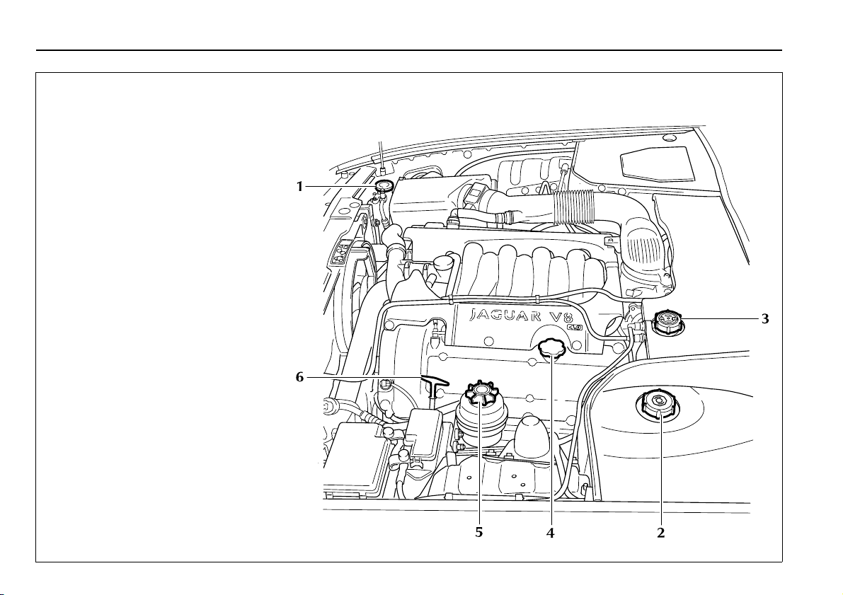
Reservoir and Dipstick Locations
1. Windscreen washer reservoir
2. Brake fluid reservoir
3. Coolant filler pressure cap
4. Engine oil filler
5. Power steering reservoir
6. Engine oil dipstick
Page 19
Routine checks 3-3
JLK-055
Checking and Replenishment
Check/Top Up Engine Oil Level
Check the oil level regularly with the
vehicle on flat, level ground.
Refer to page 3-2 for dipstick and oil filler
locations.
It is preferable to check the oil level after
the vehicle has been standing, that is,
with the engine completely cold.
If the engine has been started do not
check the oil level until the engine has
reached normal operating temperature.
Stop the engine and wait for a minimum
of 2 minutes to allow the oil to drain back
into the sump.
Remove the dipstick and wipe clean with
a non-fluffy cloth. Replace fully, then
withdraw the dipstick.
If the oil level is on or above the lower of
the two dots on the dipstick then no
additional oil is required.
If the oil level is below the lower of the
two dots, remove the oil filler cap and
add 1 quart (1 litre) of the correct
specification oil.
Lubricant and fluid specifications are
detailed on page 3-9.
Refit the filler cap and hand tighten
securely.
The supercharger (where fitted) is oil
filled-for-life and does not require any
checks to be made by the driver.
Page 20
3-4 Routine checks
JLX-174
Checking and Replenishment
(continued)
Check/Top Up Power Steering Fluid
Reservoir
Caution: It is imperative that the
power steering system does not
become contaminated in any way.
Always dispense fluid from a fresh
sealed container and clean the area
around the reservoir neck both
before and after topping up. Never
return drained fluid to the system.
See page 3-2 for power steering fluid
reservoir location.
Check the fluid level when the engine is
‘COLD’ and the vehicle is on a flat, level
surface.
Wipe clean and remove the filler cap
from the reservoir; take great care to
prevent any foreign matter from entering.
Check that the fluid level is between the
marks on the dipstick.
If necessary, top up with DEXRON III
fluid, DO NOT OVERFILL.
Should the level be very low, report the
loss of fluid to the nearest Jaguar Dealer.
Page 21
Routine checks 3-5
JLX-173
Checking and Replenishment
(continued)
Check/Top Up Windscreen Washer/
Powerwash Reservoir
See page 3-2 for windscreen washer
reservoir location.
The washer reservoir contains the fluid
for the windscreen washers and the
headlamp powerwash system (where
fitted).
Fill to just below the neck with Jaguar
Windscreen Washer Fluid diluted with
clean, preferably soft water as specified in
the instructions on the bottle.
Do not over-fill.
Using a non-approved fluid may
Note:
adversely affect the wiper blade rubber,
resulting in ineffectual and noisy wiping.
Cold Weather Precautions
To prevent damage to the pump during
freezing conditions, use Jaguar
Windscreen Washer Fluid diluted with
water to the correct strength, as shown
on the bottle, for the anticipated ambient
temperature.
Caution:
1. Windscreen washer fluid is toxic
and in concentrated form is
flammable.
2. Under no circumstances must
cooling system anti-freeze be
used, since this will damage the
paintwork.
Page 22
3-6 Routine checks
JLK-091
Checking and Replenishment
(continued)
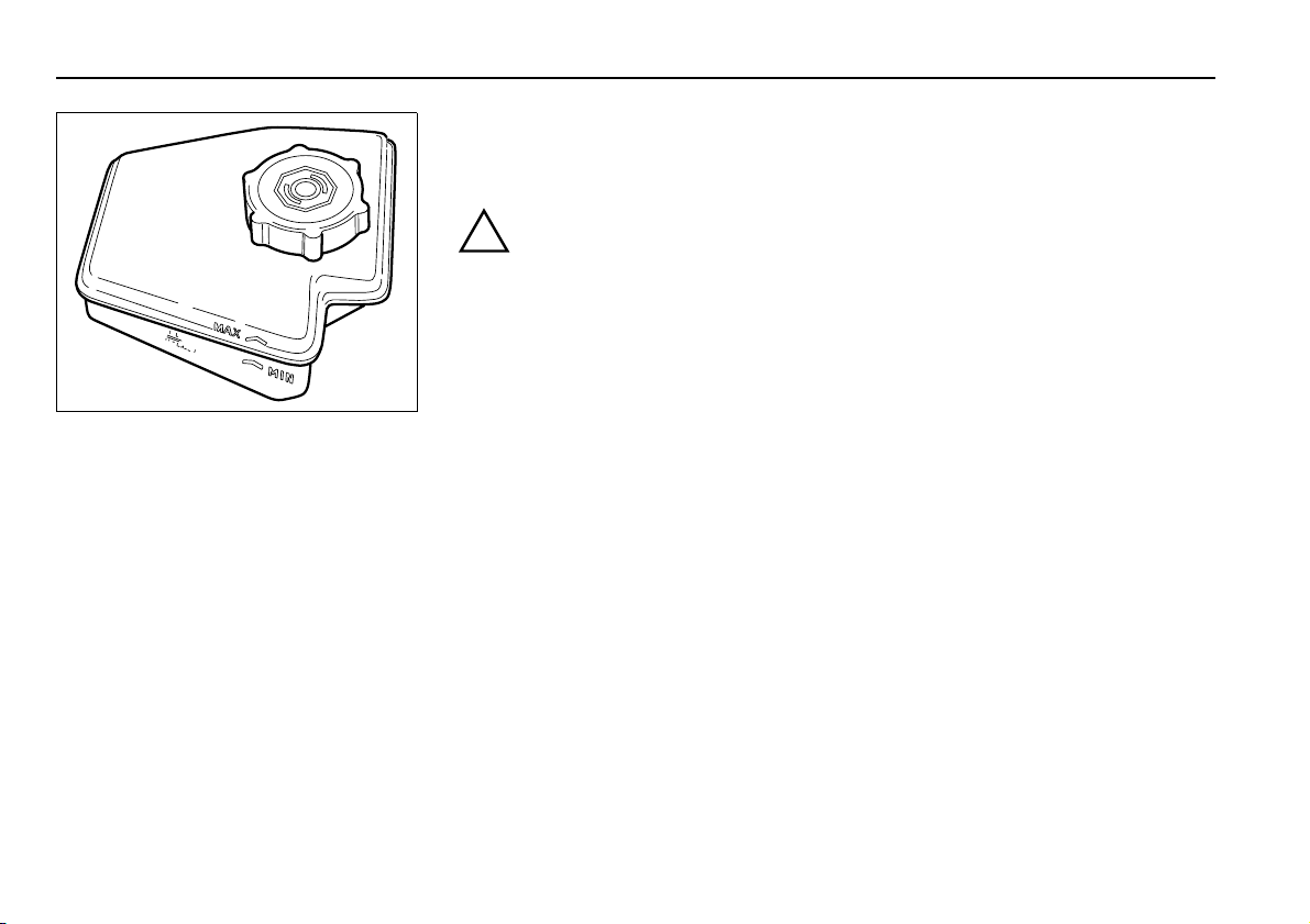
Check/Top Up Brake Fluid Reservoir
!
WARNING:
The brake fluid level will drop as the
brake pads wear. If the level is very
low report the loss of fluid to the
nearest Jaguar Dealer. Do not drive
the vehicle until the cause is rectified.
Caution:
1. While handling brake fluid, take
extreme care; brake fluid must not
contact the vehicle paintwork.
2. Always use fresh, clean fluid from
a new container. Never introduce
used brake fluid into the system.
See page 3-2 for brake fluid reservoir
location.
After removal of the cover, the fluid is
visible through the translucent casing of
the reservoir and must be maintained at
the ‘MAX’ mark.
If necessary, top up as follows:
Before removing the cap, clean the
reservoir and cap thoroughly with a lint
free cloth to ensure that no foreign matter
enters the reservoir.
Unscrew the filler cap and top up to the
‘MAX’ level using new Jaguar brake fluid,
specification Jaguar ITT SUPER DOT 4.
This is a non-mineral polyglycol based
brake fluid.
Refit the filler cap securely.
To avoid contamination should any brake
fluid be spilt, replace the cap on the
reservoir before cleaning the spilt fluid
from the vehicle.
Page 23
Routine checks 3-7
JLX-154
Checking and Replenishment
(continued)
Checking Coolant Level
The coolant level must only be checked
when the engine is COLD.
See page 3-2 for coolant header tank
location and page 3-8 for the coolant
specification.
!
WARNING:
Do not remove the coolant expansion
tank filler/pressure cap while the
engine is hot. If the cap must be
removed, protect the hands against
escaping steam and slowly turn the
cap anti-clockwise until the excess
pressure can escape. Leave the cap in
this position until all the steam and
pressure have escaped, and then
remove the cap completely.
The coolant should be level with the
bottom of the filler neck of the header
tank. If persistent coolant loss is noticed
have a Jaguar Dealer investigate the cause
immediately.
Refit the filler cap and hand tighten
securely.
Topping up
Caution: Anti-freeze will damage
paintwork. Avoid spillage.
Top up until the coolant is level with the
bottom of the filler neck.
Use the correct concentration of Jaguar
Anti-freeze/Coolant/ Corrosion Inhibitor.
Page 24

3-8 Routine checks
Cooling System
The cooling system should be filled or
topped up with a mixture of 50 per cent
demineralised water and 50 per cent
Jaguar Anti-freeze, Coolant and Corrosion
Inhibitor conforming to specification
WSS M97B44-D, coloured orange,
Extended Life Coolant.
This anti-freeze mixture gives frost
protection for temperatures down to
-40°C (-40°F).
Caution: Do not mix with anti-freeze
of a different specification as this
would damage the cooling system.
Engine Anti-freeze
Anti-freeze, when used at the correct
concentration, not only protects the
engine from frost damage in winter, it
also provides all year round protection
against internal corrosion.
Use only anti-freeze to specification
WSS M97B44-D, coloured orange,
Extended Life Coolant. Inferior quality
anti-freeze may be ineffective in
maintaining adequate frost and corrosion
protection to the cooling system.
The coolant solution may remain in the
cooling system for five years or,
150 000 miles (240 000 kilometres) after
which the cooling system should be
drained, flushed and refilled.
!
WARNING:
Do not allow anti-freeze to make
contact with skin or eyes. If this
should happen, rinse the affected
area immediately with plenty of
water.
Engine Block Heater
If the vehicle is to be started at
temperatures of –30°C (–22°F) and lower,
it is recommended that an engine block
heater is fitted and used. Failure to do so
may result in damage to the drive belt.
For further information consult your
Jaguar Dealer.
Caution: The fitting of an engine
block heater does not eliminate
(lessen) the need for anti-freeze
under freezing conditions.
Page 25

Routine checks 3-9
Recommended Engine Oil
Oil Specification
API SJ / EC and ILSAC GF-2.
When topping up between oil changes, make sure that you use
oil that has the correct quality level (API service) and viscosity
grade. Your vehicle’s warranty may be invalidated if damage is
caused by use of improper engine oil.
When the oil level is at the lower dipstick mark, add one quart
(one litre) of engine oil.
Recommended SAE Viscosity Range / Ambient Temperature Scale
SAE Viscosity Rating
It is recommended that you use only approved engine oils to
meet the SAE Viscosity Range / Ambient Temperature Scale
shown below. For maximum fuel economy, 5W/30 oil is
recommended.
JOL.654
Page 26

3-10 Routine checks
Capacities
US Quarts Litres
Engine Oil – without oil cooler . . . . . . . . . . . . . . . . . . . . . . . . . . . 6.9 6,5
– with oil cooler . . . . . . . . . . . . . . . . . . . . . . . . . . . . . 7.9 7,5
The rear axle (final drive unit), automatic transmission unit and
supercharger (where fitted) are oil filled-for-life and will not
normally require to be topped up.
Cooling system, including reservoir and climate control:
– Initial fill – 3.2 and 4.0 litre normally aspirated . . . . . . . . . . . . . . . . 10.6 10,0
– Initial fill – 4.0 litre supercharged . . . . . . . . . . . . . . . . . . . . . . . . . . 12.7 12,0
Windscreen Washer Reservoir . . . . . . . . . . . . . . . . . . . . . . . . . . . . . . . 6.6 6,3
Fuel Tank
US Gallons Litres
Indicated refill capacity (E to F on fuel gauge) 19.8 75,0
Unindicated capacity (Below E on fuel gauge) 1.6 6,0
Total refill capacity 21.4 81,0
Page 27
4 Roadside emergency service
Introduction
In the event of a flat tyre, drivers should follow closely the
procedure for wheel changing and jacking given in this section.
The correct jacking points and how to locate them are shown. It
is important that only the correct jacking points are used.
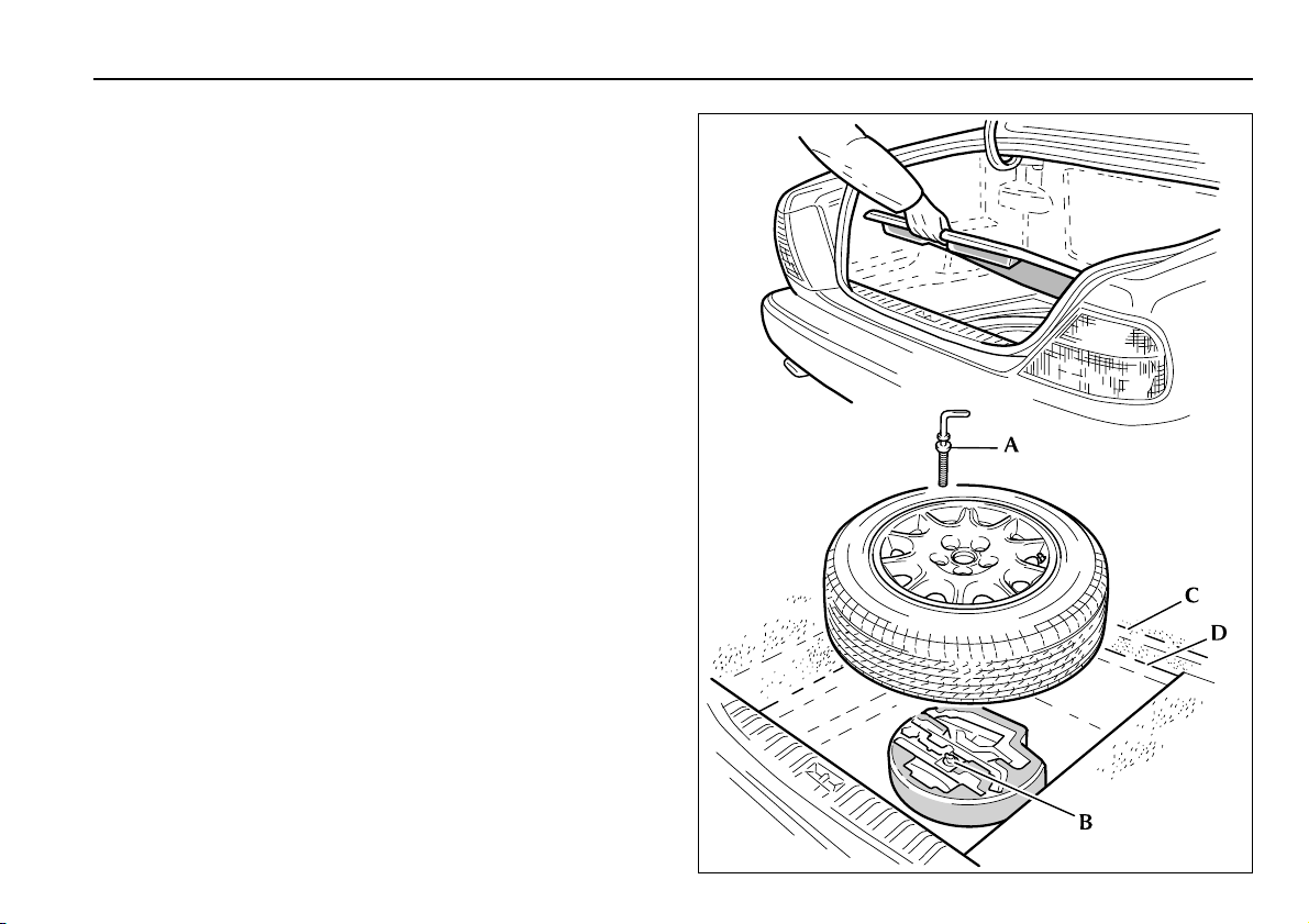
Spare Wheel and Jacking Equipment
The spare wheel, jacking equipment and wheel chock are stored
under the luggage compartment floor panel.
To remove the spare wheel, remove the luggage compartment
floor panel and unscrew the retaining screw (A).
The tray containing the jacking equipment kit can be removed
from the luggage compartment by unscrewing the yellow
securing bolt (B).
The kit comprises: the jack; jack ratchet handle with socket
extension; wheel nut wrench with telescopic extension and a
wheel chock. For vehicles fitted with locking wheel nuts, a
wheel locking nut extractor tube and key socket are included in
the tray.
Note: Examine the jack occasionally, clean and grease the
threads to ensure it is always ready for an emergency.
Stow the replaced road wheel in the luggage compartment so
that it fits over the jacking equipment tray. Reposition the
luggage compartment floor panel in the upper location slots (C).
(D) is the panel location slots for vehicles with a space saver
wheel.
Roadside emergency service 4-1
JLX-186
Page 28

4-2 Roadside emergency service
Wheel Changing and Jacking
Be prepared for a flat tyre. Know where equipment is stowed
and read the wheel changing and jacking instructions carefully.
Stopping the Vehicle
Pull off the road completely, clear of all traffic and park on as
level, solid ground as possible. Switch on hazard warning lights
and, where legally required, display the warning triangle.
!
WARNING:
It can be dangerous to change a wheel when the vehicle
is on a slope or soft, uneven ground.
Remove the spare wheel (see page 4-1) to obtain the jack and
wheel changing tools.
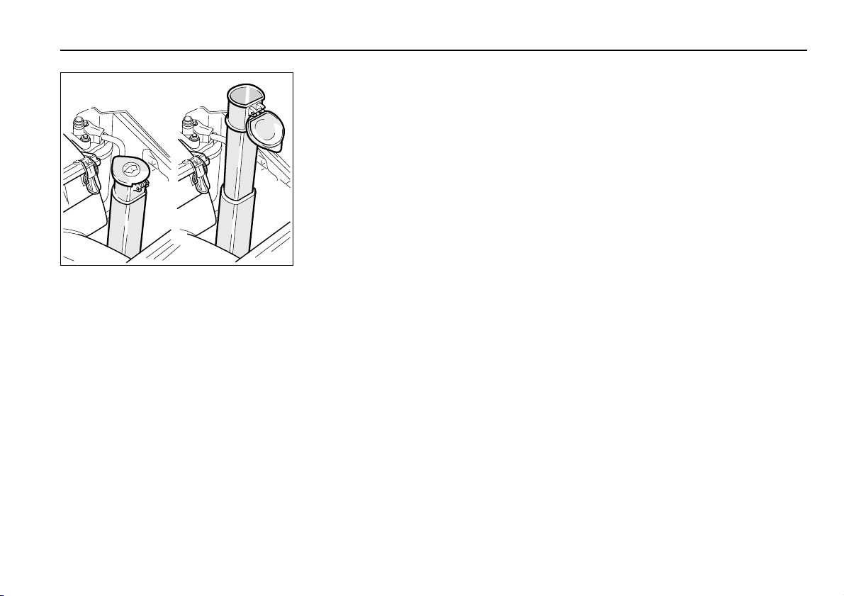
To Gain Access to the Wheel Nuts:
Alloy Wheels with Plain Wheel Nut Covers
Carefully remove the wheel nut cover using the flattened end of
the spare wheel retaining screw.
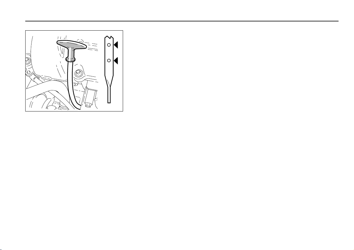
Loosening the Wheel Nuts
Always slightly loosen the wheel nuts before raising the vehicle.
A label showing correct use of the wheel nut wrench is printed
on its shaft, as shown opposite and states:
WHEEL NUT REMOVAL WHEEL NUT TIGHTEN
JLX.213
JLK 053
Page 29

Wheel Changing and Jacking (continued)
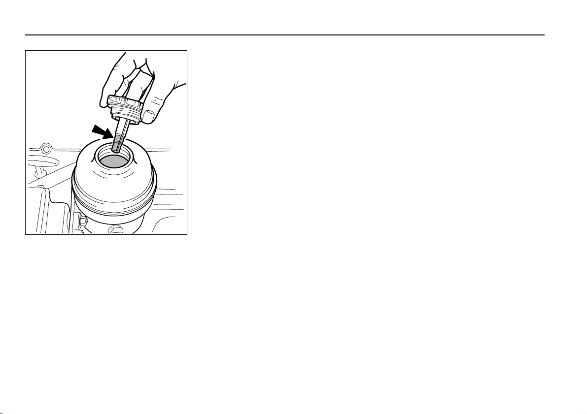
Removing Locking Wheel Nuts (where fitted)
Some vehicles are fitted with one locking wheel nut on each
wheel. These can only be removed using the extractor tube and
key socket from the jacking equipment tray.
The locking wheel nut is provided with a cover which makes it
visually similar to standard wheel nuts. The top of the cover has
an indentation (A) to aid identification.
Push the extractor tube firmly over the locking wheel nut cover,
as shown at (B), until it is fully located.
Withdraw the extractor tube to remove the cover.
Fit the key socket over the locking wheel nut as shown at (C).
Fit the wheel nut wrench over the key socket and loosen the
locking wheel nut.
Locking Wheel Nut Security Coding
Locking wheel nuts have a letter stamped on their upper
surface. The key socket is stamped with a corresponding
number. Only key sockets with the correct matching number
will fit the locking wheel nut.
Should a new key socket be required, note the letter on the
locking wheel nut and contact your Jaguar Dealer. Proof of
vehicle ownership will be required.
Roadside emergency service 4-3
JLX-156
Page 30

4-4 Roadside emergency service
Wheel Changing and Jacking (continued)
Before Lifting the Vehicle
!
WARNING:
Before attempting to lift the vehicle with the jack, chock
one of the front wheels
when jacked up.
A folding wheel chock is supplied with the jacking equipment.
The chock must be unfolded into a triangular form before use.
Chock the front wheel on the opposite side of the vehicle to the
side being jacked up, as detailed below:
VEHICLE FACING DOWN A SLOPE VEHICLE FACING UP A SLOPE VEHICLE HORIZONTAL
Chock the front of the front wheel Chock the rear of the front wheel Front wheel change: Chock at A
to prevent the vehicle from rolling
Note:
1. Ensure that all passengers are in a safe place, clear of the
vehicle.
2. Firmly apply the handbrake and select gear
position ‘P’ (Park).
3. Ensure that the jack is on firm and level ground.
Using the wheel nut wrench with the handle extended, slacken,
but do not remove, the wheel nuts.
Rear wheel change: Chock at B
JLX-155
Page 31

Wheel Changing and Jacking (continued)
Jacking
!
WARNING:
Never work under the vehicle using only the jack as a
support, always use axle stands or suitable supports
under the jacking points.
Observe the instructions printed on the jack.
Use the jack only for lifting the vehicle during wheel changing,
and only use the jack which is stored in the vehicle.
Do not start or run the engine while the vehicle is only
supported by a jack.
Note: When one rear wheel is lifted off the ground the
automatic transmission ‘P’ (Park) position will not prevent the
vehicle from moving and possibly slipping off the jack.
There are four jacking points, two each side. These provide
positive location for the jack and are on the underside of the
floor near each wheel. Remove the rubber cover from the end of
the jacking point adjacent to the road wheel to be changed.
Caution: Never use bumpers or any other part of the body
to lift the vehicle.
Roadside emergency service 4-5
JLX-143
!
WARNING:
Do not attempt to lift the vehicle unless the jack arm is
fully engaged in the jacking point square socket.
Place the jack squarely beneath the appropriate jacking point
and insert the jack arm in the jacking point square socket.
Page 32

4-6 Roadside emergency service
JLX-179
Wheel Changing and Jacking
(continued)
Ensure that the jack arm is fully engaged.
Carefully raise the vehicle by turning the
ratchet handle. Stop jacking the
vehicle when the tyre just clears the
ground. Minimum tyre lift gives
maximum vehicle stability. Remove
the wheel nuts and the wheel.
Fitting the Spare Wheel
!
WARNING:
When using the wheel nut wrench,
use the extension handle only for
removing wheel nuts, NOT for
tightening.
Fit the spare wheel and secure with the
wheel nuts.
Using the wheel nut wrench, lightly
tighten the wheel nuts alternately using
the sequence shown in the illustration.
Ensure that the taper on the wheel nuts is
seated fully onto the taper faces of the
wheel disc.
Lower the jack and, with the wrench
handle not extended, tighten the wheel
nuts alternately. At the earliest
opportunity have the wheel nuts
tightened with a torque wrench to
50–60lbf.ft (68–82Nm) for steel
wheels, and 65 – 75 lbf.ft (88 – 102 Nm)
for alloy wheels. This torque must not be
exceeded.
Remove the jack from the vehicle and
replace the jacking point rubber cover.
Page 33

Wheel Changing and Jacking (continued)
Re-fit the Centre Badge or Wheel Nut Cover
Alloy Wheels with Centre Badge
Carefully remove the centre badge to allow the wheel to be
stowed. Transfer the badge to the replacement wheel . Press fit
the centre badge into position on the wheel.
Alloy Wheels with Plain Wheel Nut Covers
Push the wheel nut cover firmly into position on the wheel.
Stowing the Equipment
Remove the chock and fold flat.
Stow the jack, wheel chock and tools in the jacking equipment
tray. If removed, refit the equipment tray in the luggage
compartment and secure with the yellow securing bolt.
Place the road wheel over the equipment tray and refit the
luggage compartment floor panel.
Roadside emergency service 4-7
JLX-212
Page 34

4-8 Roadside emergency service
Emergency Starting
Rolling Start
A start by pushing or towing cannot be achieved on a
vehicle with automatic transmission.
Emergency Starting using Jump Leads
Both the booster and discharged battery should be treated with
great care when using jump leads. Always use high quality leads
capable of carrying the starter current of the vehicle to be
started.
Before commencing, the following precautions must be taken:
1. When the battery of another vehicle is being used, ensure
that the vehicles do not touch. Alternatively, remove the
charged battery and place near to, not on, the vehicle with
the discharged battery.
2. Ensure that both vehicles have all electrical services OFF, the
handbrake is ON and the transmission is in Park.
3. Where the jump leads are of a different colour, e.g. red and
black, use red for positive (+). This aids identification and
helps to avoid crossing positive (+) to negative (–). Take extra
care to avoid crossing the polarity when using cables of the
same colour.
Caution:
1. If using a jump start vehicle, under no circumstances
should the vehicles come into contact with each other.
This could establish an earth connection, which may
cause sparks and damage.
2. Do not run the jump start vehicle’s engine when boost
starting a Jaguar Vehicle. If the jump start vehicle’s
engine is running and the jump leads are
disconnected, damage to the Jaguar vehicle’s electrical
system will result.
3. The booster battery voltage must not exceed 12 volts.
Continued
Page 35

Emergency Starting (continued)
The following procedure must be followed exactly, being careful
not to cause sparks.
1. Apply the handbrake, select Park and turn off all the vehicles
electrical services.
2. Remove the luggage compartment floor panels.
3. Unclip the battery positive (+) terminal cover.
4. Attach one end of the red jump lead to the positive (+)
terminal of the booster battery and the other end to the
positive (+) terminal of the discharged battery. Make sure
that a good connection is made.
Caution: Do not connect the negative jump lead directly
to the negative (–) terminal of the discharged vehicle.
5. Attach one end of the black jump lead to the negative (–)
terminal of the booster battery and the other end to an earth
point on the vehicle being started. (See illustration). The earth
point must be at least 12 inches (305 mm) from the
discharged battery. Make sure that a good connection is
made.
6. When started, allow the engine to idle for 5 minutes before
disconnecting the cables.
7. Disconnect the black jump lead from the earth point and the
booster battery negative (–) terminal.
8. Disconnect the red jump lead from the positive (+) terminals
of both batteries.
9. Refit the positive (+) terminal cover.
10. Refit the luggage compartment floor panels.
Roadside emergency service 4-9
JLX-180
Page 36

4-10 Roadside emergency service
Vehicle Recovery
The preferred vehicle recovery method is by using a flat bed
transporter or rear suspended tow. The front and rear towing
loops are primarily for emergency use when towing for SHORT
DISTANCES, e.g. removing the vehicle if it is causing an
obstruction or for winching the vehicle onto a recovery
transporter.
Transporting
If the vehicle is being transported on a trailer or vehicle flat bed
transporter, the handbrake must be applied, the wheels chocked
and the gear selector lever moved to position ‘N’ or ‘D’ but
NEVER to ‘P’.
The vehicle must be securely tied down to the transporter or
trailer. There are four transporter tie-down brackets on the
vehicle underbody. Do not attach tie-down hooks to the towing
loops.
Suspended Towing
Ensure that the recovery team follow these instructions:
Do not tow with sling-type equipment since damage to the
bodywork may result.
Caution: Do not tow vehicle by suspending the front end.
1. Remove the key from the ignition switch.
2. Raise the rear of the vehicle using a ‘spectacle frame’ type
lifting device where a cradle is positioned under each rear
wheel, as indicated.
Vehicles with Defective Automatic Transmission
The vehicle must be towed with the rear wheels clear of the
ground.
JLX-147
Page 37

Towing Loops
Caution: The towing loops are not suitable for ‘solid bar
towing’.
Care must be taken to avoid damaging the bumpers and
front apron.
The front loop is welded to the right-hand bumper mounting
bracket.
Turn the three fasteners (A) anti-clockwise and remove the grille
vane (B) before using the front towing loop.
The rear eye is welded to the right-hand side of the luggage
compartment underfloor panel.
Always obey towing regulations: In certain countries the
registration number of the towing vehicle and an ‘ON TOW’
sign or warning triangle must be displayed in a prominent
position at the rear of the vehicle being towed.
When being towed, the vehicle’s gear selector lever must be in
neutral (position ‘N’) with the ignition key turned to position ‘II’
to release the steering lock and render the indicators, horn and
brake lights operational.
Vehicles may be towed for SHORT DISTANCES (maximum
0.5 mile/0.8 kilometre) with the gear selector lever in
position ‘N’ provided a speed of 30 mph (48 km/h) is not
exceeded.
Roadside emergency service 4-11
JLX-176
!
WARNING:
When the engine is not running the steering and brakes
will no longer be power-assisted. Therefore, be prepared
for relatively heavy steering and the need for greatly
increased brake pedal pressure.
Page 38

4-12 Roadside emergency service
Fuses and Fuse Boxes
Fuse failure is identified by an inoperative circuit.
Do not fit a new fuse if the wiring is damaged; contact a
Jaguar Dealer. After renewing a fuse have the circuit checked by
a Jaguar Dealer.
A special tool for removing and replacing the fuses is supplied
underneath the electrical carrier lid in the luggage
compartment, together with spare fuses.
Use only the spare fuses supplied. Replace the spare with a
Jaguar approved fuse of the same amperage rating.
Checking and Renewing a Blown Fuse
Make sure the new fuse is the correct rating (amperage). Fuses
are colour coded according to the amperage and the rating is
also marked on each fuse. The colour code is as follows:
TAN 5 amp CLEAR 25 amp
RED 10 amp LIGHT GREEN 30 amp
LIGHT BLUE 15 amp BRIGHT ORANGE 40 amp
YELLOW 20 amp
JLX-145
Push the tool on to the suspect fuse and withdraw it.
If the wire in the fuse is broken, the fuse has blown.
A – Fuse in good condition. B – Blown fuse.
Fit a new fuse using the tool.
Page 39

Fuse Box Locations
There are five separate fuse boxes fitted to the vehicle, each one
containing fuses protecting a different group of circuits.
There are two types of fuse box:
Type A – 18 fuse positions with one relay
Type B – 22 fuse positions with seven relays.
The locations are as follows:
Type A Fuse boxes
B Engine management fuse box
C Rear compartment fuse box
D Rear compartment fuse box
Type B Fuse boxes
A Engine compartment fuse box
E Luggage compartment fuse box
Note: Relays are detailed on page 4-22.
Roadside emergency service 4-13
!
WARNING:
1. Do not fit a fuse of a different amperage from that
specified on the Master Label. The electrical circuits
may become overloaded with the subsequent
possibility of a fire.
2. No attempt should be made to repair a fuse that has
blown. This may cause a fire hazard or serious damage
elsewhere in the electrical circuit.
JLX-144
Page 40

4-14 Roadside emergency service
Engine Compartment Fuse Boxes
There are two fuse boxes in the main engine compartment,
located on the left-hand side. The larger of the fuse boxes, the
engine compartment fuse box, contains 22 fuse positions. The
smaller fuse box, the engine management fuse box, has 18 fuse
positions.
Caution: When a fuse box lid is removed, take care to
protect the box from moisture, and refit the lid at the
earliest opportunity.
Remove the larger fuse box lid by pressing the retaining lugs and
lifting.
When refitting, press the fuse box lid in the area of the retaining
lugs until the lid engages.
The circuits protected are listed on page 4-16.
Remove the smaller fuse box lid by compressing and lifting the
‘U’-shaped latching mechanism (A).
To refit the fuse box lid, position into the slots and push down
until the latching mechanism is engaged.
The circuits protected are listed on page 4-17.
JLK-022
JLK-023
Page 41

JLX-142
Rear Passenger Compartment Fuse
Boxes
Two fuse boxes are located behind the
right-hand and left-hand side heelboard
trim panels below the rear seat.
To detach the heelboard trim panel, turn
the fastener 90 degrees and pull the
heelboard panel forwards. Long
wheelbase vehicles with electrically
operated rear seats have a captive
heelboard which hinges upwards, after
loosening the fastener, for access to the
fuses.
Roadside emergency service 4-15
JLX-141
To refit the heelboard trim panel, first
insert the top of the panel under the seat
pan and push the bottom of the panel
until it is correctly located. Fit the
securing fastener.
The circuits protected are listed on pages
4-18 and page 4-19.
Luggage Compartment Fuse Box
A fuse box is located in the luggage
compartment electrical carrier which is
situated to the rear of the battery.
A list of protected circuits and fuse ratings
is given on the fuse allocation chart
(Master Label) which is attached to the lid
of the electrical carrier.
Caution: When the carrier lid is
removed, take care to protect the box
from moisture ingress, and refit the
lid at the earliest opportunity.
Remove the luggage compartment floor
panels.
Remove the electrical carrier lid by
pulling the retaining clips and pulling the
lid upwards.
Spare fuses and a special tool for
removing the fuses are supplied
underneath the electrical carrier lid in the
luggage compartment.
Reposition the lid and press down until
the retaining clips engage.
The circuits protected are listed on
page 4-20.
Page 42

4-16 Roadside emergency service
Fuse Ratings
Engine Compartment Fuse box – Left-hand Side
Fuse NoRatings
(amps)
1 10 Transmission control module.
2 5 Screen heaters relay, alternator regulator.
3 10 Security sounder, headlamp levelling,
ignition coils +Ve, fog lamp switches.
4 5 ABS control module.
5 10 Adaptive damping, starter relay coil, engine
management control module and relays.
6 10 Right-hand dipped beam headlamp.
7 30 Powerwash pump.
8 10 Left-hand dipped beam headlamp.
9 10 Security sounder.
10 5 Rain Sensing.
11 10 Right-hand horn.
A on location illustration, page 4-13.
Circuit
Fuse NoRatings
(amps)
12 30 Radiator cooling fans series/right-hand fast.
13 10 Left-hand horn.
14 30 Cooling fans left-hand fast.
15 10 Air conditioning coolant pump.
16 30 ABS pump control.
17 15 Front fog lamps.
18 30 ABS pump motor.
19 10 Right-hand main beam headlamp.
20 – Not used.
21 10 Left-hand main beam headlamp.
22 30 Wiper motor.
Circuit
Page 43

Fuse Ratings and Circuits
Engine Compartment – Engine Management Fuse box
Roadside emergency service 4-17
Fuse NoRating
(amps)
1 20 Adaptive damping.
2 15 Intercooler water pump (Supercharger).
3 25 Starter solenoid.
4 5 Engine control module.
5 10 Fuel injectors.
6 5 Transmission control module.
7–Not used.
8 10 Air conditioning compressor clutch.
9 30 Throttle motor.
10 5 Engine control module, Park/Neutral switch,
cruise control VSV 1 and 2 (where fitted),
EGR valves.
B on location illustration, page 4-13.
Circuit
Fuse NoRating
(amps)
11 30 HO2 sensor heaters.
12 10 Air flowmeter, VVT solenoids.
13 – Not used.
14 10 HO2 sensor heaters relay (where fitted),
EVAP valve, ignition coils relay, throttle
motor relay, AC compressor clutch relay,
radiator fans control module, CCV.
15 30 Windscreen left-hand heater.
16 5 Control module compartment cooling fan.
17 30 Windscreen right-hand heater.
18 10 Ignition coils, ignition amplifier.
Circuit
Page 44

4-18 Roadside emergency service
Rear Compartment Fuse box – Right-hand Heelboard
Fuse NoRating
(amps)
1 20 Left-hand seat control module.
2 15 Door lock relay, door locking actuators.
3 15 Body processor module.
4 10 Door mirror heaters, mirror foldback.
5 5 Passenger seat switchpack.
6 10 Air conditioning.
7 20 Body processor module (column motor
power).
8 5 Rear window switchpack, passenger door
switchpack.
9 20 Rear seat heaters.
10 5 Jaguar Diagnostic System.
C on location illustration, page 4-13.
Circuit
Fuse NoRating
(amps)
11 20 Air conditioning right-hand blower relay.
12 5 Right-hand / left-hand rear seat timer.
13 25 Right-hand rear door control module.
14 - Not used.
15 25 Right-hand door control module.
16 - Not used.
17 15 Sunroof.
18 25 Right-hand and left-hand seat heaters.
Circuit
Page 45

Rear Compartment Fuse box – Left-hand Heelboard
Roadside emergency service 4-19
Fuse NoRating
(amps)
1 20 Right-hand seat control module.
2 5 Rear window switchpack, driver door key
barrel, driver door switchpack and memory.
3 5 Dimmer module.
4 5 Diagnostic connector.
5 15 Body processor module.
6 5 Centre console switchpack (includes clock),
reader exciter ECM.
7 15 Body processor module (battery supply for
solenoids, lamps and motors).
8 5 Steering column adjust switch, driver seat
switchpack.
9 10 Radio/cassette head unit.
10 5 Airbag/SRS.
11 20 Air conditioning left-hand blower motor.
D on location illustration, page 4-13.
Circuit
Fuse NoRating
(amps)
12 10 Door mirror heaters relay, air conditioning,
blower motor relays, power steering control
module.
13 25 Left-hand rear window.
14 10 Cruise control switch, instrument cluster,
catalytic converter over temperature
warning.
15 25 Left-hand door control module.
16 5 Electrochromic interior mirror (where fitted),
centre console switchpack, gear selector,
traction control switch illumination, J-gate
mode switch illumination. Pin A9 luggage
compartment fuse box, heated rear window
relay, fuel pump relay, secondary fuel pump
relay (supercharged). Pin A5: feed to fuses 10
& 12 in right-hand heelboard.
17 10 Accessory supply.
18 5 Instrument cluster.
Circuit
Page 46

4-20 Roadside emergency service
Luggage Compartment Fuse box – Electrical Carrier
Fuse NoRating
(amps)
1 10 Security and locking control module
(Reversing lamps, rear fog lamps, stop lamps,
electrochromic mirror).
2 5 Fuel filler flap.
3 5 Audio system.
4 5 Radio telephone, ‘E’ post lamps, navigation.
5 25 Cigar lighters.
6 - Not used.
7 20 Fuel pump.
8 10 High mounted stop lamp, caravan/trailer
stop lamps.
9 10 Antenna motor.
10 10 Security and locking control module (luggage
compartment release, caravan/trailer
direction indicators, fuel filler flap relay).
E on location illustration, page 4-13.
Circuit
Fuse NoRating
(amps)
11 10 Accessory sockets.
12 30 Audio system power amplifier.
13 - Not used.
14 5 Navigation.
15 20 Fuel pump (supercharger, where fitted).
16 20 Caravan/trailer connector.
17 25 Heated rear screen.
18 20 Rear seat movement.
19 5 Right-hand side lamps, left-hand and
right-hand number plate lights, caravan/
trailer.
20 20 Rear seat movement.
21 5 Left-hand side lamps, left-hand and
right-hand sidemarker lights, caravan/trailer.
22 5 Audio / telephone.
Circuit
Page 47

Control Modules – Identification and Location
Roadside emergency service 4-21
Control Module Location
Adaptive Damping
(where fitted)
Airbag (Supplementary
Restraint System)
Anti-lock Braking
System and Traction
Control
Body Processor Fascia, mounted on passenger airbag
Climate Control Right-hand side of the climate control
Under the fascia, on the bulkhead,
passenger side.
On the tunnel forward of the J-gate.
Engine compartment, left-hand side.
Mounted below the ABS hydraulic
control unit.
bracket.
unit.
Control Module Location
Door (four-one in each
door)
Engine Management Engine compartment, passenger side,
Front Seat Seat cushion frame.
Rear Seat (where fitted) Rear of the centre armrest.
Security and Locking Luggage compartment electrical
Transmission Engine compartment, passenger side,
Door interior, between the inner and
outer panels.
within bulkhead extension.
carrier to the rear of the battery.
within bulkhead extension.
Page 48

4-22 Roadside emergency service
Relay Identification and Location
The following chart identifies and gives locations for the relays
which control the vehicle’s electrical services. The relays have
coloured harness connectors and cases for identification. Where
the connector colour differs from the case, both colours will be
listed.
Location Functions Case Colour
Engine compartment fuse box, left-hand side,
to the rear of the brake control modulator.
Luggage compartment fuse box, to the rear of
the battery, under the electrical carrier lid.
Layout as diagram:
R1 Air conditioning water pump.
R2 Front fog lamps.
R3 Main beam headlamps.
R4 Power wash pump (where fitted).
R5 Dipped beam headlamps.
R6 Horns.
R7 Ignition +.
Layout as diagram:
R1 Fuel pump s/c only.
R2 Heated rear window.
R3 Tail and number plate lamps.
R4 Fuel pump.
R5 Stop lamps.
R6 Accessory socket (where fitted).
R7 Auxiliary +.
Relays, where not mounted in a fuse box, are arranged in groups
of three. Each group has a black plastic cover, which slots into
the harness connector and can be easily removed for access.
When left-hand or right-hand is used in the text, this refers to
the left-hand side or right-hand side of the vehicle, viewed from
the rear.
ÿþ
ÿ
ÿ
Brown
Brown
Brown
Brown
ÿ
ÿÿÿ
Brown
Brown
Brown
Brown
ÿþÿÿÿÿÿÿ
Brown
Brown
Brown
Brown
Brown
Brown
Page 49

Relay Identification and Location (continued)
Location Functions Case Colour
Roadside emergency service 4-23
Engine compartment, engine and
transmission control modules compartment,
passenger side.
Engine compartment, left-hand side, engine
management fuse box
Engine compartment, left-hand side behind
the radiator.
Engine compartment, centrally at bulkhead. Front screen heater – right-hand side (where fitted).
Engine compartment, left-hand side, below
the brake modulator under spoiler.
Layout as diagram:
R1 Intercooler water pump
(where fitted), (micro-relay).
R2 Air conditioning compressor clutch.
R3 Ignition coil.
R4 Throttle motor.
R5 Starter solenoid.
R6 HO2 sensor heaters.
R7 Fuel injection (micro-relay).
Engine management system control. Brown
Wiper on/off
Wiper fast/slow.
Front screen heater – left-hand side (where fitted).
Radiator fan control module. Black
ÿÿÿÿÿ ÿ
Black
Brown
Brown
Brown
Brown
Brown
Black
Black
Black
Black
Black
Page 50

4-24 Roadside emergency service
Relay Identification and Location (continued)
Location Functions Case Colour
In the passenger compartment below the
driver seat.
In the passenger compartment below the
front passenger seat.
In the passenger compartment behind the
right-hand side rear seat heelboard.
In the passenger compartment behind the
left-hand side rear seat heelboard.
In the passenger compartment in the
left-hand side rear seat fuse box.
In the luggage compartment fuse box. Fuel flap lock: micro-relay.
Seat heater – driver (where fitted). Brown
Seat heater – front passenger (where fitted). Brown
Right-hand blower – air conditioning: micro-relay.
Left-hand blower – air conditioning: micro-relay.
Door mirror heater: micro-relay.
Left-hand lumbar deflate, rear seat: micro-relay (where fitted).
Door lock: micro-relay.
Air conditioning isolate: micro-relay
Door mirror fold flat: micro-relay (where fitted).
Door mirror fold out: micro-relay (where fitted).
Ignition + Brown
Fuel flap unlock: micro-relay.
Black
Black
Black
Black
Black
Black
Black
Black
Black
Black
Page 51

5 Vehicle maintenance
Vehicle maintenance 5-1
Introduction
Owners are responsible for ensuring that
the vehicle is regularly maintained and
serviced at the correct mileage/time
intervals as specified in the ‘Maintenance
Schedules’. The first part of this section
deals with regular servicing.
The condition of the tyres is of the utmost
importance. Advice about tyre wear and
correct usage is given in this section. If in
any doubt about the condition of your
tyres, contact a Jaguar Dealer.
Regular Servicing
Regular maintenance and servicing is the
responsibility of the owner.
Jaguar Dealers will be pleased to arrange
periodic servicing in accordance with the
USA and Mexico
Booklet or Canadian
Warranty and Benefits Information
Booklet.
Failure to implement maintenance at the
recommended intervals could result in
deterioration of vehicle performance and
possible infringement of regulations.
‘Passport to Service’
‘Club Jaguar’
Tool Kit
A tool kit is provided for some vehicles/
markets and is located under the bonnet,
on the passenger side, in a tray on the
bulhead extension cover.
Tyres
Tyres of the correct type and dimensions,
with correct cold inflation pressures are
an integral part of every vehicle’s design.
Regular maintenance of tyres contributes
not only to safety, but to the designed
function of the vehicle. Road-holding,
steering and braking are especially
vulnerable to incorrectly pressurised,
badly fitted or worn tyres.
Tyres of the correct size and type but of
different make have widely varying
characteristics. It is therefore
recommended that Jaguar approved tyres
(see SECTION 6:
fitted to all wheels.
Wheel/Tyre Data
) are
Do not interchange tyres from side to
side, front to rear or vice versa as tyre
wear produces characteristic patterns
depending upon their position and, if the
position is changed after wear has
occurred, the performance of the tyre will
be adversely affected.
Tyre Repair
It is recommended that damaged tyres
are discarded and new tyres fitted. They
must not be repaired in view of the high
performance capability of the vehicle.
Page 52

5-2 Vehicle maintenance
Tyre Use after Vehicle Storage
After a long period of a vehicle standing,
tyres may become locally distorted with a
flat area. This will cause an uneven ride
for a few miles until the tyres have
warmed up and the ‘flat’ rounds off.
However, to reduce the effects of
flat-spotting, the tyres of a stored vehicle
may be inflated to pressures not
2
exceeding 50 lbf/in
Refer to SECTION 6,
Tyre Pressures
(343 kPa, 3,4 bar).
Recommended
for normal operating
pressures.
Tyre Size, Type, Pressures
The tyre pressures recommended (see
SECTION 6:
Wheel/Tyre Data
) provide
optimum ride and handling
characteristics for all normal operating
conditions. The pressures should be
checked, and correctly set, if necessary,
once per week. This should be done with
the tyres cold. Tyre temperatures and
pressures increase when running.
Deflating a warm tyre to the
recommended pressure will result in
under-inflation which may be dangerous.
A slight natural pressure loss occurs with
2
time. If this exceeds 2 lbf/in
(0,14 kg/cm
2
, 0,14 bar) per week, the
(14 kPa,
cause should be investigated and
rectified.
It is an offence in many States and certain
other countries to drive a vehicle with
tyres that are not inflated in accordance
with the vehicle’s proper use.
A vehicle fitted with winter tread tyres
must only be driven at speeds below the
speed rating moulded into the tyre’s
side-wall.
Tyre Renewal
When renewal of tyres is necessary it is
preferable to fit a complete vehicle set.
Should either front or rear tyres only
show need for renewal, new tyres must
be fitted, as axle sets, to replace worn
ones.
After new tyres have been fitted
Note:
the wheels need to be dynamically
balanced.
The radial ply tyres specified are designed
to meet the high-speed performance
capability of this vehicle.
Only tyres of identical specification as
shown in SECTION 6:
Wheel/Tyre Data
must be fitted. Do not fit tyres with a
different tread pattern, size or speed
rating.
Damage
Excessive local distortion can cause the
casing of a tyre to fracture and may lead
to premature failure. Tyres should be
examined especially for cracked walls,
exposed cords, etc. Flints and other sharp
objects must be removed from the tyre
tread; if left in they may work through the
cover. Clean off any oil or grease
contamination by using a suitable
cleaner.
Caution: Do not use paraffin
(kerosene), because this has a
detrimental effect on rubber.
Page 53

Wear
All tyres fitted as original equipment include tread wear
indicators (TWI) in their tread pattern. When the tread has worn
to a remaining depth of 0.063 inch (1,6 mm) the indicators
appear at the surface as bars which connect the tread pattern
across the full width of the tyre.
It is illegal in many States and certain other countries to
continue to use tyres after the tread has worn to less than
0.063 inch (1,6 mm) over three quarters of the width and the
entire circumference of the tyre.
It should be noted that the properties of many tyres alter
progressively with wear. In particular the ‘wet grip’ and
aquaplaning resistance are gradually but substantially reduced.
Extra care and speed restriction should therefore be exercised
on wet roads as the effective tread depth diminishes.
Incorrect wheel alignment will accelerate tyre wear. Fins on the
inner or outer edges of the tread pattern are caused by excessive
toe-in or toe-out respectively. As fins may also be caused by high
cornering speeds or road camber, it is advantageous to have the
cause detected by having the wheel alignment checked.
Vehicle maintenance 5-3
JLK-046
Page 54

5-4 Vehicle maintenance
Snow Chains and Spikes Spiders
Snow chains or a ‘Spikes Spider’
accessory, of the recommended type, may
only be fitted to rear wheels. Contact
your Jaguar Dealer for details and
availability of approved snow chains or
spikes spiders.
Traction control (if fitted) MUST be
Note:
switched OFF when using snow chains or
spikes spiders.
The maximum speed when using snow
chains or spikes spiders is 30 mph
(48 km/h).
Remove the snow chains or spikes spiders
immediately the roads are clear of snow.
Ensure the fitting instructions supplied
with the snow chains or spike spiders are
kept in a safe place, for example, the
Vehicle Care literature pack.
Due to the constraints of
Note:
wheelarch clearance, snow chains can
only be used up to a maximum size of 16
inch diameter roadwheels. Spike spiders
can be used up to a maximum of 18 inch
diameter roadwheels.
Care of Alloy Road Wheels
The alloy road wheels are covered with a
protective coating. To prevent corrosion it
is essential that this coating is not
damaged.
When removing or fitting tyres always
advise the tyre fitter to treat the alloy
wheels with great care and to only use
equipment with spigot or stud hole
clamping. The equipment must not have
any moving parts which contact the
wheel, and tyre levers must not be used.
Always ensure that the wheel nuts are
fully seated before finally tightening the
nuts in alternate sequence.
Page 55

Vehicle maintenance 5-5
!
WARNING:
United States Department of
Transportation/Uniform Tyre Quality
Grades
The following information relates to the
tyre grading system developed by the
National Highway Safety Traffic
Administration which will grade tyres by
tread wear, traction and temperature
performance.
Tread Wear
The tread wear grade is a comparative
rating based on the wear rate of the tyre
when tested under controlled conditions
on a specified government test course.
For example, a tyre graded 150 would
wear one and a half (1½) times as well on
the government course as a tyre graded
100. The relative performance of tyres
depends upon the actual conditions of
their use, however, and may depart
significantly from the norm due to
variations in driving habits, service
practices and differences in road
characteristics and climate.
Traction - A, B, C
The traction grades, from the highest to
the lowest are A, B, C, and they represent
the tyre’s ability to stop on wet
pavements as measured under controlled
conditions on specified government test
surfaces of asphalt and concrete. A tyre
marked ‘C’ may have poor traction
performance.
!
WARNING:
The traction grade assigned to this
tyre is based on braking (straight
ahead) traction tests and does not
include cornering (turning) traction.
Temperature - A, B, C
The temperature grades ‘A’ (the highest),
‘B’ and ‘C’ representing the tyre’s
resistance to the generation of heat and
its ability to dissipate heat when tested
under controlled conditions on a
specified indoor laboratory test wheel.
Sustained high temperature can cause the
material of the tyre to degenerate and
reduce tyre life, and excessive
temperature can lead to sudden tyre
failure.
The grade ‘C’ corresponds to a level of
performance which all passenger car
tyres must meet under the Federal Motor
Vehicle Safety Standard N
Grades ‘B’ and ‘A’ represent higher levels
of performance on the laboratory test
wheel than the minimum required by
law.
The temperature grade for this tyre is
established for a tyre that is properly
inflated and not overloaded.
Excessive speed, under inflation or
excessive loading, either separately
or in combination, can cause heat
build-up and possible tyre failure.
o.
109.
Page 56

5-6 Vehicle maintenance
Battery
A low maintenance battery specifically
designed for use with this vehicle is fitted
in the luggage compartment.
Under normal operating conditions the
battery requires minimal maintenance.
However, in hot weather conditions it is
advisable to check the battery electrolyte
levels at regular intervals.
!
WARNING:
1. The cell plugs and vent pipe must
be in place at all times when the
battery is in the vehicle. Failure to
fit, or incorrect fitting of these
items is potentially hazardous.
2. To avoid injury do not use an open
flame or cause an electric spark
when checking the battery.
Hydrogen gas generated by the
battery is flammable and may
explode.
3. Do not connect any 12 volt
equipment, (for example, a 12 volt
lead lamp), directly to the battery
terminals. Use the cigar lighter
sockets for temporarily
connecting Jaguar approved
accessories.
4. Do not let battery acid come into
contact with skin or eyes. If you
get electrolyte in your eyes or on
your skin, immediately rinse with
cold water and consult a doctor.
Caution:
1. Switch off current before
disconnecting battery terminals.
Always disconnect the earth
terminal first and reconnect last.
2. Do not let battery acid come into
contact with painted surfaces or
fabric.
The exterior of the battery should be
occasionally wiped clean to remove any
dirt or grease.
If a new battery is to be fitted, it must be
the same type as the original. The use of
unapproved batteries is not
recommended and could invalidate the
vehicle warranty.
The service life of the battery is
Note:
dependent on its condition of charge. It
must always be sufficiently charged for the
battery to last an optimum length of time.
We recommend that the battery charge is
checked frequently if the vehicle is used
mostly for short distance trips, or if it is
not used for long periods of time.
Generator (GEN)
To prevent damage to the generator, do
not run the engine while the battery or
any of the charging circuit cables are
disconnected.
The generator has polarity-sensitive
components that may be irreparably
damaged if subjected to incorrect
polarity. Ensure that the battery earth
lead is always connected to the battery
negative
(–) terminal.
Page 57

Vehicle maintenance 5-7
JLK-090
Check/Top Up Battery Electrolyte
In normal climates this must be
Note:
carried out at least once a year. In hot
weather/climates the electrolyte level
must be checked at least every three
months.
Remove the luggage compartment floor
panel and the right-hand side panel.
Unscrew the six cell plugs. Check that the
electrolyte is level with the plastic level
indicator (A). If necessary, top up with
distilled water but do not overfill. If
illumination is required, use a hand-held
flashlight to inspect the electrolyte level.
Refit the six cell plugs.
Refit the floor panels.
Battery Charging
!
WARNING:
Batteries produce combustible gas
(hydrogen) when being charged. The
battery must be removed from the
vehicle before charging commences.
To disconnect the battery, refer
to
Battery Lead Disconnection
page 5-8.
When charging the battery ensure that
the charge voltage is the same as the
nominal voltage of the battery.
Caution: Switch off the charger before
connecting or disconnecting terminal
connections to avoid sparks and short
circuits.
on
Ensure that the charger positive (+) lead
is connected to the positive (+) terminal
of the battery and the negative (–) lead is
connected to the negative (–) terminal of
the battery.
Do not remove or loosen any of the cell
plugs when charging the battery.
Check, and if necessary top-up, the
electrolyte level when the battery is fully
charged.
Clean and Grease Battery
Connections
Disconnect the battery leads as detailed
in
Battery Lead Disconnection
page 5-8. Clean the battery posts and
coat the post bases with petroleum jelly.
Reconnect the battery leads as detailed in
Battery Lead Connection
on
on page 5-8.
Page 58

5-8 Vehicle maintenance
Battery Lead Disconnection
Upon battery lead disconnection, both trip computer
Note:
memories (A and B) will be erased. On reconnection the radio
will require recoding and the clock will need to be reset.
Remove the luggage compartment floor panel and the
right-hand side panel (where fitted).
Caution:
1. Under no circumstances should a battery be
disconnected whilst the ignition circuit is live, as
permanent damage to the instrument cluster may
occur.
2. Disconnect the negative lead (earth terminal) first.
Unclip the battery positive terminal cover.
Slacken the negative lead pinch bolt (10 mm spanner required)
and disconnect the
positive lead pinch bolt and disconnect the
lead.
Battery Lead Connection
Caution: Do not overtighten the pinch bolts.
Connect the
the positive terminal cover on the battery.
Connect the
the floor panels.
negative
positive
negative
(–) battery lead. Slacken the
positive
(+) lead, tighten the pinch bolt and clip
(–) lead and tighten the pinch bolt. Refit
(+) battery
After the battery has been reconnected and the ignition switch is
turned to position ‘II’, the message centre display will initially
show an erroneous reading i.e. – – – – – –. This will remain until
after the bulb check sequence, when the correct recorded
mileage will be displayed. This is a normal function of the
instrument pack.
Reset the clock to the correct time.
The radio cassette player display will indicate ‘code’. The radio
will not operate until the correct security code has been
re-entered. Refer to the Sound System Handbook.
JLK-027
Page 59

Bulb Renewal
It is important that only Jaguar bulbs of the type specified on
page 5-18 are used when renewing bulbs.
Before renewing bulbs, switch off the ignition and light switches.
Headlamp – Bulb Renewal
Open the bonnet.
Identify the position of the bulb assembly on the rear of the
headlamp unit.
Dip beam bulb is outboard.
High beam bulb is inboard.
Caution: The bulbs are halogen type and will be damaged
if touched by hand or contaminated with oil or grease. It
is important to use clean gloves or cloth when handling a
bulb which is to be used again. A contaminated bulb may
be cleaned with methylated spirit before refitting.
Press the plastic spring clips and remove the bulb holder from
the headlamp assembly. Pull the bulb from the bulb holder.
Always use the correct bulb for the application, as specified on
page 5-18.
Fit a new bulb to the bulb holder, it will only correctly fit in one
position. Fit the bulb holder to the headlamp, it will only
correctly fit in one position, and engage the spring clips.
Close the bonnet.
Vehicle maintenance 5-9
JLX-168
Page 60

5-10 Vehicle maintenance
Front Parking (Side) Light – Bulb Renewal
Open the bonnet.
The front parking lights are contained within the inner
headlamp units.
Rotate the bulb holder anti-clockwise and remove from the
headlamp.
Pull the capless bulb from the holder and fit a new one of the
correct type, see page 5-18.
Reposition the bulb holder in the headlamp unit and turn
clockwise.
Close the bonnet.
Front Fog Lamp – Bulb Renewal
It is recommended that the front fog lamp bulb is renewed by a
Jaguar Dealer.
JLX-182
Page 61

Front Direction Indicator – Bulb Renewal
To remove the light unit:
edge of the lamp unit. This will release the lamp sufficiently to
insert a flat blade (take care not to damage the paintwork) into
the gap at the outboard end of the light unit to compress the
spring catch. The unit can then be removed from the bumper.
Disconnect the plug from the lamp. Remove the bulb and fit a
new one of the correct type, see page 5-18.
Reconnect the plug, then insert the unit into the bumper
aperture, inboard end first. Press in until the catch clicks.
Push gently inwards on the inboard
Vehicle maintenance 5-11
JLX-185
Page 62

5-12 Vehicle maintenance
Side marker light - Bulb renewal
Press the edge of the lens facing the centre of the vehicle to
release the first stage catch. Insert a flat blade into the aperture,
taking care not to damage the paintwork and press to release
the second stage spring catch. The unit can then be removed
from the bumper.
Twist the bulb holder anti-clockwise and remove from the unit.
Pull out the bulb and fit a new bulb of the correct type, see
page 5-18. Refit the bulb holder to the unit.
Insert the unit into the bumper aperture, outboard end first.
Press in until the catch clicks.
JLX-181
Page 63

Rear Light Assembly – Bulb Renewal
The rear light assembly has the following bulbs:
(A) Fog light.
(B) Stop/tail light.
(C) Reverse light.
(D) Direction Indicator.
Open the luggage compartment and remove the rear light unit
cover.
Ensure that the lights and ignition switch are OFF before
removing any bulbs.
Turn the bulb holder fastener 90° anti-clockwise and carefully
remove the bulb holder.
Remove the faulty bulb and fit a new one of the correct type, as
illustrated on the bulb holder. Fitment of the correct type is
essential, see page 5-18.
Refit the bulb holder assembly and turn the fastener 90°
clockwise.
Refit the light unit cover.
Vehicle maintenance 5-13
JLX-161
Page 64

5-14 Vehicle maintenance
JLX-162
JLX-163
Luggage Compartment Light – Bulb
Renewal
Carefully prise the light unit from the
luggage compartment trim panel.
Turn the bulb holder a quarter turn to
remove the holder from the lens. Pull the
bulb from the holder.
Fit a new bulb of the correct type,
see page 5-18.
Fit the bulb holder assembly to the lens
and turn 90 degrees.
Refit the light unit to the luggage
compartment trim panel.
Number Plate Light – Bulb Renewal
Remove the two retaining screws and the
lens and gasket. Remove the bulb and fit
a new one of the correct type,
see page 5-18.
Refit the lens and gasket and secure with
the two screws.
Page 65

Vehicle maintenance 5-15
JLX-167
JLX-165
Glove Box Light – Bulb Renewal
Open the glove box and carefully prise
the lens from the left-hand side of the
glove box.
Remove the bulb from the bulb holder
and fit a new one of the correct type,
see page 5-18.
Refit the lens into the glove box.
JLX-164
Rear Quarter Interior/Reading Light –
Bulb Renewal
Carefully prise the top end of the light
unit out of the trim panel using a thin
blade with card protection against the
trim panel.
Unplug the connector (B), ease back the
lens retention clip (A), and remove the
lens.
Remove bulb(s) and fit a new one of the
correct type, see page 5-18.
Plug in the connector, hook the base of
the lens into the bottom end of the light
unit and clip fully home.
Refit the light unit into the trim panel,
inserting the bottom end first.
Sun Visor Vanity Mirror Light – Bulb
Renewal
Swing the sun visor downwards and lift
the vanity mirror flap. Using a
screwdriver carefully prise the lens from
the sun visor. Remove the bulb from the
holder and fit a new one of the correct
type, see page 5-18. Refit the lens.
Page 66

5-16 Vehicle maintenance
JLX-166
Door Guard Light – Bulb Renewal
Remove the red/clear lens by carefully inserting a flat blade
screwdriver through the access hole at the bottom of the lens, to
disengage the clip leg, then slide the lens down.
Remove the bulb and fit a new one of the correct type,
see page 5-18.
Refit the lens.
JLX-169
High Mounted Stop Light – Bulb Renewal
Depress the two spring clips (A) at the base of the lamp cover (B)
and withdraw the cover. Remove the lamp module from the
base by releasing the spring clips at each end (C).
Remove the red lens from the bulb holder (D).
Taking care not to touch the reflective surfaces, remove the
bulb (E) from the holder and fit a new one of the correct type,
seepage5-18.
Fit the red lens to the bulb holder, fit the lamp module to the
base and replace the cover.
Page 67

Roof Console Interior/Reading Lights – Bulb Renewal
Press the button on the roof console to open the sun-glasses
stowage compartment.
Turn the fastener located in the sun-glasses compartment 90°
anti-clockwise. Lower the roof console rear end slightly and
withdraw it rearwards. Unplug the connector and place the
console on a soft, clean surface.
Remove the six screws from the main housing screw positions as
identified on the moulding, then ease the housing away from
the console.
Remove the bulb(s) and fit new ones of correct type, as
illustrated on the moulding, fitment of the correct type is
essential, see page 5-18.
Replace the main housing locating the bulb end first, then
replace the screws – do not over tighten.
Reconnect the roof console connector and refit the console,
with the front end first, then locate the rear and secure with the
fastener.
Close the sun-glasses compartment.
Vehicle maintenance 5-17
JLX-157
Page 68

5-18 Vehicle maintenance
Bulb Chart
Description Capacity Type
Door guard light. 12V 5W Capless long life.
Flasher side repeater. 12 V 5 W Capless long life.
Fog lamp – Front. 12V 51W Halogen HB4 long life.
Fog light – Rear. 12V 21W Bayonet long life.
Front direction
indicator.
Front parking (side)
light.
Glovebox light. 12V 4W Bayonet long life.
Headlamp. 12V 55W Halogen H7 long life.
High mounted stop
light.
Luggage compartment
light.
12V 21W Bayonet long life.
12V 5W Capless long life.
12V 5W Capless long life.
12V 5W Capless long life.
Description Capacity Type
Number plate light. 12V 5W Festoon long life.
Rear direction
indicator.
Rear quarter courtesy
light (lower section).
Rear quarter reading
light (upper section).
Reverse light. 12V 21W Bayonet long life.
Roof console central
courtesy light.
Roof console map light. 12V 6W Capless.
Stop/tail light. 12V 21/5W Twin filament bayonet
Sun visor vanity mirror
light.
12V 21W Bayonet amber long
life.
12V 5W Capless long life.
12V 6W Capless long life.
12V 5W Capless long life.
long life.
12V 1.2W Capless 286.
Page 69

Windscreen Wiper Blade
The wiper blade rubber insert will be renewed at every
Note:
service interval, except for the 40,000 mile (64,000 km) interval
when the complete wiper blade is renewed (chargeable to
customer).
Use Jaguar Screen Clean Paste to remove contamination from
the windscreen to ensure effective wiping or if smearing or
juddering becomes evident. A more aggressive cleaning agent
may be required to remove stubborn contamination. Contact a
Jaguar Dealer for advice.
To ensure that the windscreen remains smear free, the washer
system should be operated whenever the wiper is used, even
when it is raining.
Vehicle maintenance 5-19
Windscreen Wiper Blade – Inspect and Clean
Lift the wiper blade clear of the windscreen and wipe the blade
with a clean, soft cloth moistened with water to which a mild
liquid detergent has been added.
Inspect the wiper blade, and if there any signs of wear or
damage; renew the blade.
Renew the wiper blade before and after each winter, or more
often if required.
JLX-187
Windscreen Washers
The windscreen washer tube and nozzles are mounted on the
wiper arm to apply the washer fluid directly to the windscreen.
Page 70

5-20 Vehicle maintenance
Page 71

6 Specifications
Specifications 6-1
Vehicle Data
Engine 4.0 litre normally aspirated 4.0 litre supercharged
Type . . . . . . . . . . . . . . . . . . . . . . . . . . . . . . . . . . . . V8, dual overhead camshafts
4 valves/cylinder.
Capacity . . . . . . . . . . . . . . . . . . . . . . . . . . . . . . . . .
Bore . . . . . . . . . . . . . . . . . . . . . . . . . . . . . . . . . . . . 3.386 inch (86 mm) 3.386 inch (86 mm)
Stroke . . . . . . . . . . . . . . . . . . . . . . . . . . . . . . . . . . . 3.386 inch (86 mm) 3.386 inch (86 mm)
Firing order: 1A and 1B cylinders at front of engine 1A, 1B, 4A, 2A, 2B, 3A, 3B, 4B 1A, 1B, 4A, 2A, 2B, 3A, 3B, 4B
Compression ratio . . . . . . . . . . . . . . . . . . . . . . . . . 10.75 : 1 9.0 : 1
Spark plugs (unleaded fuel):
– Type . . . . . . . . . . . . . . . . . . . . . . . . . . . . . . . . . .
– Electrode gap . . . . . . . . . . . . . . . . . . . . . . . . . . .
Spark plugs (leaded fuel):
– Type . . . . . . . . . . . . . . . . . . . . . . . . . . . . . . . . . .
– Electrode gap . . . . . . . . . . . . . . . . . . . . . . . . . . .
Transmission
Type – Automatic . . . . . . . . . . . . . . . . . . . . . . . . . . 5 Speed 5 Speed
Final drive type . . . . . . . . . . . . . . . . . . . . . . . . . . . . GKN 14HU
244 inch
NGK PFR5G-11E
0.04 - 0.043 inch (1.0 - 1.1 mm)
NGK BKR5E-11
0.04 inch (1.0 mm)
On centre line differential
3
(3996 cm3) 244 inch3 (3996 cm3)
V8, dual overhead camshafts
4 valves/cylinder.
NGK PFR5G-11E
0.04 - 0.043 inch 91.0 - 1.1 mm)
NGK BKR5E-11
0.04 inch (1.0 mm)
GKN 14HU
On centre line differential
Page 72

6-2 Specifications
Weights
Note:
Kerb weight . . . . . . . . . . . . . . . . . . . . . . . . . . . . . . . . . . . 1789 3945 1810 3990
Front axle kerb weight . . . . . . . . . . . . . . . . . . . . . . . . . . . 923 2035 924 2038
Rear axle kerb weight . . . . . . . . . . . . . . . . . . . . . . . . . . . . 866 1910 885 1952
Gross vehicle weight (G.V.W.) . . . . . . . . . . . . . . . . . . . . . 2218 4890 2240 4940
Gross front axle weight. . . . . . . . . . . . . . . . . . . . . . . . . . . 1016 2240 1018 2245
Gross rear axle weight . . . . . . . . . . . . . . . . . . . . . . . . . . . 1202 2650 1222 2695
Gross combination weight . . . . . . . . . . . . . . . . . . . . . . . . 4117 9078 4140 9128
(Average/Approximate)
Gross combination weight is the gross vehicle weight plus recommended trailer weight.
XJ8
(Standard Wheelbase)
kg lb kg lb
(Extended Wheelbase)
XJ8-L
Page 73

Specifications 6-3
Weights
Note:
Kerb weight . . . . . . . . . . . . . . . . . . . . . . . . . . . . . . . . . . . 1848 4075 1814 4000
Front axle kerb weight. . . . . . . . . . . . . . . . . . . . . . . . . . . 960 2117 941 2075
Rear axle kerb weight . . . . . . . . . . . . . . . . . . . . . . . . . . . 888 1958 873 1925
Gross vehicle weight (G.V.W.) . . . . . . . . . . . . . . . . . . . . . 2270 5005 2245 4950
Gross front axle weight . . . . . . . . . . . . . . . . . . . . . . . . . . 1055 2325 1036 2285
Gross rear axle weight . . . . . . . . . . . . . . . . . . . . . . . . . . . 1215 2680 1209 2665
Gross combination weight . . . . . . . . . . . . . . . . . . . . . . . . 4169 9193 4144 9138
(Average/Approximate) (continued)
Gross combination weight is the gross vehicle weight plus recommended trailer weight.
XJR8 supercharged
kg lb kg lb
VDP supercharged
VDP
Page 74

6-4 Specifications
Weights
Roof-Rack Capacity and Trailer Weights
Roof-rack capacity including weight of rack . . . . . . . . . . . 100 220
Maximum permitted luggage compartment load with
four passengers and driver . . . . . . . . . . . . . . . . . . . . . . . . 70 154
Trailer weight:
Braked (recommended) . . . . . . . . . . . . . . . . . . . . . . . . . . 1500 3307
Braked (maximum recommended) . . . . . . . . . . . . . . . . . . 1900 4188
Unbraked (maximum recommended) . . . . . . . . . . . . . . . . 750 1653
Trailer nose load . . . . . . . . . . . . . . . . . . . . . . . . . . . . . . . 76 167
(Average/Approximate) (continued)
(all Models)
kg lb
Page 75

Specifications 6-5
Dimensions
Standard Wheelbase Extended Wheelbase
mm inch mm inch
Overall length . . . . . . . . . . . . . . . . . . . . . . . . . . . . . . . . . 5024 197.8 5149 202.7
Overall width including mirrors. . . . . . . . . . . . . . . . . . . . 2074 81.7 2074 81.7
Overall width excluding mirrors . . . . . . . . . . . . . . . . . . . 1799 70.8 1799 70.8
Overall height (at gross vehicle weight):
– 3.2 and 4.0 litre with comfort suspension. . . . . . . . . .
– 3.2 and 4.0 litre with sports suspension . . . . . . . . . . .
Minimum ground clearance (at gross vehicle weight) . . . . 115 4.5 115 4.5
Wheelbase. . . . . . . . . . . . . . . . . . . . . . . . . . . . . . . . . . . . 2870 113.0 2995 117.9
Track:
Front . . . . . . . . . . . . . . . . . . . . . . . . . . . . . . . . . . . . . . . .
Rear. . . . . . . . . . . . . . . . . . . . . . . . . . . . . . . . . . . . . . . . .
1314
1307
1500
1498
51.7
51.5
59.1
59.0
1333
1326
1500
1498
52.5
52.2
59.1
59.0
Turni n g circle :
Kerb to kerb . . . . . . . . . . . . . . . . . . . . . . . . . . . . . . . . . . 11,83 metre 38 feet 10 inches
Page 76

6-6 Specifications
Wheel/Tyre Data
Wheel name Road wheel size Tyre type/size
Starburst alloy
Crown alloy
Corona alloy
Lunar alloy
Solar alloy 7½J x 1
Asteroid alloy 8J x 18 Pirelli P Zero 255/40 ZR 18
7J x 16 Pirelli P 4000E 225/60 ZR 16 or Pirelli P 6000 225/60 ZR 16
7
Pirelli P 6000 235/50 ZR 17
Page 77

Specifications 6-7
Wheel/Tyre Data
Winter (Snow) Tyres
The tyres fitted as original equipment are designed with a
rubber compound, tread pattern and width specially suited for
high speeds in normal road conditions, but they are less suitable
during extremes of low temperatures, snow and ice. The use of
winter tyres will considerably improve the vehicle’s handling
during these conditions.
It is recommended that only Jaguar approved winter tyres are
used.
16 inch wheels and tyres cannot be fitted to the Jaguar XJR
Note:
or VDP Supercharged (225/55 R 16 or 225/60 R 16).
– Tyre type/size. Pirelli Winter 210 Performance M+S
(continued)
225/55 R 16 or:
225/60 R 16 or:
255/45 R 17 or:
255/40 R 18
Continental ContiWinterContact
225/55 R 16 95H or
225/60 R 16 98H
Caution: Tyre directional indicators must be rotating in a
clockwise direction when viewed from the right-hand
side of the vehicle, and anti-clockwise when viewed from
the left-hand side of the vehicle.
Do not exceed 130 mph (210 km/h) when using Jaguar approved
winter tyres.
Winter tyres must be used in vehicle sets, that is, fitted on all
four wheels.
For information on snow chains, or a ‘Spikes Spider’ accessory,
see page 5-4.
Page 78

6-8 Specifications
Recommended Tyre Pressures
Tyres must be inflated to the following cold inflation pressures:
Maximum comfort –
Speeds up to 160 km/h (100 mph)
16, 17 and 18 Inch
Wheels/Tyres
Front
Rear
26 lbf/in
28 lbf/in2, (190 kPa 2,0 kg/cm2, 1,9bar) 34lbf/in2, (230 kPa 2,4 kg/cm2, 2,3 bar)
2
, (180 kPa 1,8 kg/cm2, 1,8bar) 32lbf/in2, (220 kPa 2,24 kg/cm2, 2,2 bar)
Tyres without Jaguar approval
Tyres other than those recommended must be inflated to the
following cold inflation pressure (front and rear):
2,
44 lbf/in
, (300 kPa, 3,1 kg/cm2, 3,0 bar)
When using non-Jaguar approved winter tyres, inflate to the
above recommended tyre pressure and do not exceed the tyre's
speed capability.
Normal Pressures
Page 79

Specifications 6-9
Fuel Requirements
Use only Premium Unleaded gasoline with a minimum
Anti-Knock Index (AKI) of 91.
Oxygenated gasoline blended with ethanol (max. 10%)
methanol (max 10%) or
methyl tertiary butyl ether (MTBE) (max. 15%) may be
used.
Reformulated Gasoline with a minimum AKI of 91 may
also be used
The use of high quality fuel containing ‘intake system deposit
control’ detergent and other additives will help to keep the
vehicle’s intake system free of deposits and its fuel system free
of corrosion and gumming.
If high quality fuels containing ‘intake system deposit control’
detergent and other additives are used continuously, there
should be no need to add any after market products to the fuel
tank.
If problems are experienced with starting, rough idling or
hesitation when the engine is cold, it may be caused by gasoline
with a low volatility. Try a different grade and/or brand of fuel. If
the condition persists, see a Jaguar Dealer or a qualified service
technician.
Oxygenated gasoline
Fuels that are blended with compounds containing oxygen,
called oxygenates, may be used. Common oxygenates are
ethanol or grain alcohol (blended at no more than 10%),
methanol or wood alcohol (blended at no more than 5% with
necessary co-solvents and additives, and MTBE or methyl
tertiary butyl ether (blended at no more than 15%). The type of
oxygenate may be found on the fuel pump or by asking the
attendant. In certain areas of the country, oxygenates are
required to be in all fuels to help improve air quality.
Generally, difficulty should not be experienced while operating
the vehicle on fuels containing oxygenates. If problems are
experienced switch to a fuel with a different type of oxygenate,
or switch to a fuel that does not contain oxygenates, if available.
Reformulated gasoline
Several petroleum companies have announced the availability of
reformulated fuels.
These fuels are specially designed to further reduce vehicle
emissions.
Jaguar fully supports all efforts to protect and maintain ambient
air quality, and encourage the use of reformulated gasoline,
where available.
Page 80

6-10 Specifications
Catalytic Converters
A few precautions on the use of vehicles fitted with catalytic
converters are necessary. These are:
1. In order to maintain the efficiency of the emission control
system it is essential that unleaded fuel is used. Use of leaded
fuel will seriously damage the catalytic converters.
2.
3. Heavy impact on the converter casings must be avoided.
4. The engine settings must not be altered; they have been
5. A correctly tuned engine optimises exhaust emissions,
6. Do not continue to operate the vehicle if any engine
leave the vehicle unattended with the engine running.
Never
established to ensure that the vehicle will comply with
stringent exhaust emission regulations. Incorrect engine
settings could cause unusually high catalytic converter
temperatures and thus result in damage to the converter and
vehicle. If adjustment to the settings is considered necessary,
this should be performed by a Jaguar Dealer.
performance and fuel economy and it is recommended that
the vehicle is regularly maintained.
malfunction is evident; malfunctions should be rectified
immediately. For instance, misfire, loss of engine
performance, excessive oil consumption or engine run-on
may lead to unusually high catalytic converter temperatures
and may result in damage to the converters and vehicle.
7. The use of catalytic converters increases exhaust system
temperatures, therefore, do not operate or park the vehicle
in areas where combustible materials such as dry grass or
leaves may come into contact with the exhaust system.
8. Do not run the engine with either a spark plug lead
disconnected or a spark plug removed. Do not use any device
that requires an insert into a spark plug hole in order to
generate air pressure e.g. tyre pump, paint spray attachment
etc., as this could also result in catalytic converter damage.
9. The vehicle is designed for normal road use. Below are
examples of abuse which could damage the catalytic
converters and vehicle. These may lead to a dangerous
condition due to excessively high catalytic converter
temperatures.
• Competition or off-road use.
• Excessive engine speed.
• Overloading the vehicle.
• Switching off the engine whilst in gear.
Page 81

7 Accessories
Accessories 7-1
Electrical Accessories
The fitment of accessories, additional accessory supply sockets,
relays and fuses must only be entrusted to a Jaguar Dealer.
Caution:
1. The use of any accessories not specifically designed for
this Jaguar will damage the electrical circuits and
systems of the vehicle.
2. Under no circumstances must the power supply be
obtained directly from either battery terminal.
3. The use of non-approved accessories can reduce the
battery capacity and charge period to an unacceptable
level, therefore Jaguar cannot accept any liability for
the fitment of any such item.
The cigar lighter sockets can be used for plug-in accessories
which are only temporarily connected to the vehicle (for
example, a car vacuum cleaner).
Electrical Accessory Supply Sockets
Two electrical accessory supply sockets are provided in the
following areas:
1. Behind the heelboard panel on the right-hand side of the
rear seat.
2. In the luggage compartment, clipped forward of the battery.
Before connecting electrical accessories to these sockets,
Note:
consult a Jaguar Dealer.
Earth Points
If an accessory needs to be connected to an earth point, consult
a Jaguar Dealer.
Caution: Under no circumstances must holes be drilled in
the bodywork to accept earth terminals.
Page 82

7-2 Accessories
Page 83

Index
Accessories . . . . . . . . . . . . . . . . . . . . . . . . . . . . . . . . . . . 7- 1
Aerial – Care . . . . . . . . . . . . . . . . . . . . . . . . . . . . . . . . . . 2-3
Anti-freeze . . . . . . . . . . . . . . . . . . . . . . . . . . . . . . . . . . . 3 - 8
Automatic Car Wash . . . . . . . . . . . . . . . . . . . . . . . . . . . . 2-1
B
Battery . . . . . . . . . . . . . . . . . . . . . . . . . . . . . . . . . . . . . . 5- 6
– Charging . . . . . . . . . . . . . . . . . . . . . . . . . . . . . . . . . . . 5- 7
– Connections – Clean and Grease . . . . . . . . . . . . . . . . 5- 7
– Electrolyte – Check/Top Up . . . . . . . . . . . . . . . . . . . . 5-7
– Lead Connection . . . . . . . . . . . . . . . . . . . . . . . . . . . . 5- 8
– Lead Disconnection . . . . . . . . . . . . . . . . . . . . . . . . . . 5-8
Battery/Ignition Isolator Switches . . . . . . . . . . . . . . . . . . 1- 7
Bonnet Release . . . . . . . . . . . . . . . . . . . . . . . . . . . . . . . . 1-8
Bonnet Release Control . . . . . . . . . . . . . . . . . . . . . . . . . 1-8
Brake Fluid Reservoir . . . . . . . . . . . . . . . . . . . . . . . . . . . 3-6
– Check/Top Up . . . . . . . . . . . . . . . . . . . . . . . . . . . . . . 3-6
Bulb
– Chart . . . . . . . . . . . . . . . . . . . . . . . . . . . . . . . . . . . . . 5- 18
– Renewal . . . . . . . . . . . . . . . . . . . . . . . . . . . . . . . . . . . 5-9
C
Capacities . . . . . . . . . . . . . . . . . . . . . . . . . . . . . . . . . . . . 3 -10
– Cooling System . . . . . . . . . . . . . . . . . . . . . . . . . . . . . . 3- 10
– Fuel Tank . . . . . . . . . . . . . . . . . . . . . . . . . . . . . . . . . . 3- 10
– Windscreen Washer Reservoir . . . . . . . . . . . . . . . . . . 3-10
Care
– of the exterior . . . . . . . . . . . . . . . . . . . . . . . . . . . . . . 2 -1
– of the interior . . . . . . . . . . . . . . . . . . . . . . . . . . . . . . . 2-3
Catalytic . . . . . . . . . . . . . . . . . . . . . . . . . . . . . . . . . . . . . 6-10
Catalytic Converters . . . . . . . . . . . . . . . . . . . . . . . . . . . . 6 - 10
Cleaning
– Carpets . . . . . . . . . . . . . . . . . . . . . . . . . . . . . . . . . . . 2-3
– Headlining . . . . . . . . . . . . . . . . . . . . . . . . . . . . . . . . . 2 -3
– Leather Upholstery . . . . . . . . . . . . . . . . . . . . . . . . . . . 2-3
– Underbonnet . . . . . . . . . . . . . . . . . . . . . . . . . . . . . . . 2 - 3
Control Modules
– Identification and Location . . . . . . . . . . . . . . . . . . . . . 4- 21
– Locations . . . . . . . . . . . . . . . . . . . . . . . . . . . . . . . . . . 4 - 21
Coolant Level . . . . . . . . . . . . . . . . . . . . . . . . . . . . . . . . . 3 -7
– Check/top up . . . . . . . . . . . . . . . . . . . . . . . . . . . . . . . 3- 7
Cooling System . . . . . . . . . . . . . . . . . . . . . . . . . . . . . . . . 3-8
D
Dealers . . . . . . . . . . . . . . . . . . . . . . . . . . . . . . . . . . . . . . 1- 1
Dimensions . . . . . . . . . . . . . . . . . . . . . . . . . . . . . . . . . . . 6 -5
Dipstick Locations . . . . . . . . . . . . . . . . . . . . . . . . . . . . . . 3 - 2
E
Page 84

Index
Earth Points . . . . . . . . . . . . . . . . . . . . . . . . . . . . . . . . . . .7- 1
Electrical Accessories . . . . . . . . . . . . . . . . . . . . . . . . . . . .7 - 1
Electrical Accessory Supply Sockets . . . . . . . . . . . . . . . . .7 - 1
Emergency Starting . . . . . . . . . . . . . . . . . . . . . . . . . . . . .4-8
– Using Jump Leads . . . . . . . . . . . . . . . . . . . . . . . . . . . .4 - 8
Engine and Throttle Settings . . . . . . . . . . . . . . . . . . . . . .1-7
Engine Block Heater . . . . . . . . . . . . . . . . . . . . . . . . . . . .3-8
Engine Oil
– Level . . . . . . . . . . . . . . . . . . . . . . . . . . . . . . . . . . . . . .3 -3
•Check/Top Up . . . . . . . . . . . . . . . . . . . . . . . . . 3 - 3
– Recommended . . . . . . . . . . . . . . . . . . . . . . . . . . . . . .3-9
Engine Oil – Used . . . . . . . . . . . . . . . . . . . . . . . . . . . . . .1-7
Exterior Care . . . . . . . . . . . . . . . . . . . . . . . . . . . . . . . . . .2 -1
F
Fuel
– Requirements . . . . . . . . . . . . . . . . . . . . . . . . . . . . . . .6 - 9
Fuelling and Refuelling
– Catalytic Converters . . . . . . . . . . . . . . . . . . . . . . . . . .6-10
Fuse Box
– Engine Compartment . . . . . . . . . . . . . . . . . . . . . . . . .4 - 14
– Luggage Compartment . . . . . . . . . . . . . . . . . . . . . . . .4-15
– Rear Passenger Compartment . . . . . . . . . . . . . . . . . . .4 -15
Fuse Box Locations . . . . . . . . . . . . . . . . . . . . . . . . . . . . .4- 13
Fuse Ratings . . . . . . . . . . . . . . . . . . . . . . . . . . . . . . . . . .4-16
Fuses . . . . . . . . . . . . . . . . . . . . . . . . . . . . . . . . . . . . . . . .4-12
– Checking and Renewing . . . . . . . . . . . . . . . . . . . . . . .4-12
Fuses and Fuse Boxes . . . . . . . . . . . . . . . . . . . . . . . . . . .4-12
G
General Information . . . . . . . . . . . . . . . . . . . . . . . . . . . .1 - 1
General Precautions . . . . . . . . . . . . . . . . . . . . . . . . . . . . 1 -6
Generator . . . . . . . . . . . . . . . . . . . . . . . . . . . . . . . . . . . .5-6
Glass Surfaces – Cleaning . . . . . . . . . . . . . . . . . . . . . . . . 2 - 2
Grease and Tar Removal . . . . . . . . . . . . . . . . . . . . . . . . . 2 - 1
H
Hydraulic Fluid . . . . . . . . . . . . . . . . . . . . . . . . . . . . . . . . 1 - 7
I
Interior Care . . . . . . . . . . . . . . . . . . . . . . . . . . . . . . . . . . 2 -3
J
Jacking . . . . . . . . . . . . . . . . . . . . . . . . . . . . . . . . . . . . . . .4-5
Jaguar Dealers . . . . . . . . . . . . . . . . . . . . . . . . . . . . . . . . . 1- 1
Jaguar Diagnostic System . . . . . . . . . . . . . . . . . . . . . . . . .1 - 1
L
Labels . . . . . . . . . . . . . . . . . . . . . . . . . . . . . . . . . . . . . . . 1 - 5
Leather Upholstery – Cleaning . . . . . . . . . . . . . . . . . . . . .2-3
Lubricant – Engine Oil . . . . . . . . . . . . . . . . . . . . . . . . . . .3- 9
P
Paint Chips . . . . . . . . . . . . . . . . . . . . . . . . . . . . . . . . . . . 2 - 3
Polishing . . . . . . . . . . . . . . . . . . . . . . . . . . . . . . . . . . . . .2-2
Power Steering Fluid . . . . . . . . . . . . . . . . . . . . . . . . . . . . 3 -4
Power Steering Fluid Reservoir – Check/Top Up . . . . . . .3-4
Precautions – General . . . . . . . . . . . . . . . . . . . . . . . . . . .1 - 6
R
Page 85

Index
Regular Checks . . . . . . . . . . . . . . . . . . . . . . . . . . . . . . . . 3- 1
– Daily . . . . . . . . . . . . . . . . . . . . . . . . . . . . . . . . . . . . . 3- 1
– Monthly . . . . . . . . . . . . . . . . . . . . . . . . . . . . . . . . . . . 3 - 1
– Weekly . . . . . . . . . . . . . . . . . . . . . . . . . . . . . . . . . . . . 3-1
Regular Servicing . . . . . . . . . . . . . . . . . . . . . . . . . . . . . . 5- 1
Relay Identification . . . . . . . . . . . . . . . . . . . . . . . . . . . . . 4- 22
Relay Identification and Location . . . . . . . . . . . . . . . . . . 4- 22
Reservoir and Dipstick Locations . . . . . . . . . . . . . . . . . . 3- 2
Roof Rack Capacity . . . . . . . . . . . . . . . . . . . . . . . . . . . . . 6- 4
S
Safety Precautions . . . . . . . . . . . . . . . . . . . . . . . . . . . . . 1-3
Safety Warning and Caution Labels . . . . . . . . . . . . . . . . . 1-5
Servicing . . . . . . . . . . . . . . . . . . . . . . . . . . . . . . . . . . . . . 5- 1
– Regular . . . . . . . . . . . . . . . . . . . . . . . . . . . . . . . . . . . 1-1
Snow Chains . . . . . . . . . . . . . . . . . . . . . . . . . . . . . . . . . . 5- 4
Spare Fuse Location . . . . . . . . . . . . . . . . . . . . . . . . . . . . 4-12
Spare Wheel and Jacking . . . . . . . . . . . . . . . . . . . . . . . . . 4- 1
Spare Wheel Stowage . . . . . . . . . . . . . . . . . . . . . . . . . . . 4-2
Spikes Spiders . . . . . . . . . . . . . . . . . . . . . . . . . . . . . . . . . 5 - 4
T
Tool Kit . . . . . . . . . . . . . . . . . . . . . . . . . . . . . . . . . . . . . 5 - 1
Towing . . . . . . . . . . . . . . . . . . . . . . . . . . . . . . . . . . . . . . 4- 10
– Suspended Recovery . . . . . . . . . . . . . . . . . . . . . . . . . 4 - 10
Towing Loops . . . . . . . . . . . . . . . . . . . . . . . . . . . . . . . . . 4 -11
Trailer Weights . . . . . . . . . . . . . . . . . . . . . . . . . . . . . . . . 6 - 4
Transporting . . . . . . . . . . . . . . . . . . . . . . . . . . . . . . . . . . 4-10
Tyres . . . . . . . . . . . . . . . . . . . . . . . . . . . . . . . . . . . . . . . 5 - 1
– Damage . . . . . . . . . . . . . . . . . . . . . . . . . . . . . . . . . . . 5-2
– Pressures . . . . . . . . . . . . . . . . . . . . . . . . . . . . . . . . . . 6-8
– Renewal . . . . . . . . . . . . . . . . . . . . . . . . . . . . . . . . . . . 5- 2
– Repairs . . . . . . . . . . . . . . . . . . . . . . . . . . . . . . . . . . . . 5 -1
– Use after Vehicle Storage . . . . . . . . . . . . . . . . . . . . . . 5-2
– Use and care . . . . . . . . . . . . . . . . . . . . . . . . . . . . . . . 5 - 1
– Wear . . . . . . . . . . . . . . . . . . . . . . . . . . . . . . . . . . . . . 5-3
– Winter (Snow) . . . . . . . . . . . . . . . . . . . . . . . . . . . . . . 6 -7
U
Underbonnet cleaning . . . . . . . . . . . . . . . . . . . . . . . . . . 2 -3
V
Page 86

Index
Valet Kit . . . . . . . . . . . . . . . . . . . . . . . . . . . . . . . . . . . . .2- 1
Vehicle
– Data . . . . . . . . . . . . . . . . . . . . . . . . . . . . . . . . . . . . . .6- 1
– Recovery . . . . . . . . . . . . . . . . . . . . . . . . . . . . . . . . . . .4 -10
W
Warning symbols . . . . . . . . . . . . . . . . . . . . . . . . . . . . . . .1-3
Washing . . . . . . . . . . . . . . . . . . . . . . . . . . . . . . . . . . . . .2- 1
Weights . . . . . . . . . . . . . . . . . . . . . . . . . . . . . . . . . . . . . .6-2
Wheel Changing and Jacking . . . . . . . . . . . . . . . . . . . . . .4-2
Wheel Chocking . . . . . . . . . . . . . . . . . . . . . . . . . . . . . . .4-4
Wheel Jacking and Changing . . . . . . . . . . . . . . . . . . . . . .4-1
Wheel/Tyre Data . . . . . . . . . . . . . . . . . . . . . . . . . . . . . . .6- 6
Wheels
– Care of . . . . . . . . . . . . . . . . . . . . . . . . . . . . . . . . . . . .5- 4
– Cleaning . . . . . . . . . . . . . . . . . . . . . . . . . . . . . . . . . . .2- 2
– Locking Nuts . . . . . . . . . . . . . . . . . . . . . . . . . . . . . . . .4-3
Windscreen
– Washers . . . . . . . . . . . . . . . . . . . . . . . . . . . . . . . . . . .5- 19
– Wiper Blade . . . . . . . . . . . . . . . . . . . . . . . . . . . . . . . . 5 - 19
•Inspect, Clean and Renew . . . . . . . . . . . . . . . .5 - 19
Windscreen Washer/Powerwash Reservoir . . . . . . . . . . .3- 5
– Check/Top Up . . . . . . . . . . . . . . . . . . . . . . . . . . . . . . .3 - 5
Winter (Snow) Tyres . . . . . . . . . . . . . . . . . . . . . . . . . . . .6-7
Page 87

Page 88

JJM 18 16 12/00
 Loading...