

Ironman Fitness Magnetic Rower Power 10 User Manual
Owners Manual
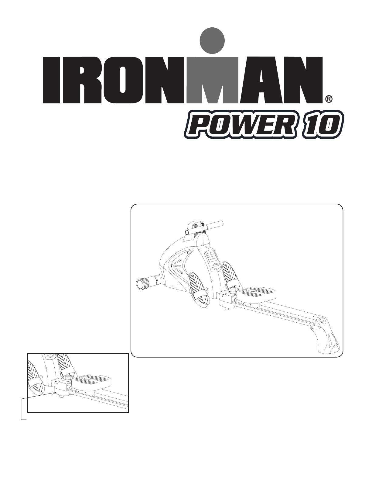
Power 10 Magnetic Rower
Customer Service
(800) 750-4766
Assembly
(888) 559-8810
Manufactured by:
Ironman Fitness Products
4009 Distribution Drive
Suite 250
Garland, TX 75041
www.ironmantness.com
Serial tag is located on the side of the track
Model Name: ________________
Date of Purchase: ________________
Serial Number: ________________
715-00001
03/19 Rev C
Caution!
Read all precautions and instructions in
this manual before using this equipment.

Table of Contents
Table of Contents 2
Important Safety Information 3
Getting Started 4
Assembly Steps 5
Parts Identifier 5
Assembly Steps 5
Console Instructions 9
Warm Up Excercises 14
Monitoring Your Heart Rate 17
Workout Information 19
Frequency: How Often Should You Exercise 19
Intensity: How Hard Should You Exercise 19
Weight Management 18
Exercise Practice Procedures 19
Workout: Brisk and Rhythmic Exercise 20
Cool Down: Slow and Relaxed Exercise 20
Chest Strap Information 21
Notes 22
Parts List 25
Exploded Views 26
Warranty 27
2

Important Safety information
WARNING! Before using this unit or starting any exercise program, consult
your physician. This is especially important for persons over the age of 35 and/or
persons with pre-existing health problems. The manufacturer or distributor assumes
no responsibility for personal injury or property damage sustained by or through the
use of this product.
WARNING! To reduce the risk of electrical shock, burns, re, or other possible
injuries to the user, it is important to review this manual and the following precautions before operation.
SAFETY PRECAUTIONS AND TIPS
1. It is the owner’s responsibility to ensure that all users of this unit have
read the Owner’s Manual and are familiar with warnings and safety pre
cautions.
2. This unit has a user maximum capacity of 275 pounds.
3. The unit should only be used on a level surface and is intended for in
door use only. The unit should not be placed in a garage, patio, or near
water and should never be used while you are wet. Ironman Fitness
recommends a mat be placed under the unit to protect oor or carpet
and for easier cleaning.
4. Follow safety information in regards to plugging in your unit. Do not run
the power cord underneath your unit. Do not operate the unit with a
damaged or frayed power cord.
5. Wear comfortable, good-quality walking or running shoes and appropri
ate clothing. Do not use the unit with bare feet, sandals, socks or stock
ings.
6. Always examine your unit before using to ensure all parts are in working
order.
7. Allow the unit to fully stop before dismounting.
8. Pets should never be allowed near the unit.
9. Do not leave children unsupervised near or on the unit.
10. Never operate the unit where oxygen is being administered, or where
aerosol products are being used.
11. Never insert any object or body parts into any opening.
12. For safety and to prevent damage to your unit, no more than one person
should use the unit at a time.
13. Always unplug the unit before cleaning and/or servicing. Service to your
unit should only be performed by an authorized service representative,
unless authorized and/or instructed by the manufacturer.
14. Failure to follow these instructions will void the unit warranty.
3
Getting Started
(..cont.)
Thank you for purchasing the Ironman Fitness Power 10 Magnetic Rower!
The quality product you have chosen was designed to meet your needs for cardiovascular exercise. Before you start, please read the Owner’s Manual and become familiar
with the operation of your new unit. Remember to take time to perform stretching
exercises, provided in this manual, to help avoid injury.
If you are taking medication, consult your physician to see what effect the
medication will have on your exercise heart rate.
If you have heart problems, you are not active, and/or are over the age of 35
years, do not use the pre-set programs or start an exercise program without rst
contacting and receiving approval from your physician.
To avoid the risk of electrical shock, always keep the console dry. Do not spill liquids
on the console. Ironman Fitness recommends a sealed water bottle for beverages
consumed while using the unit.
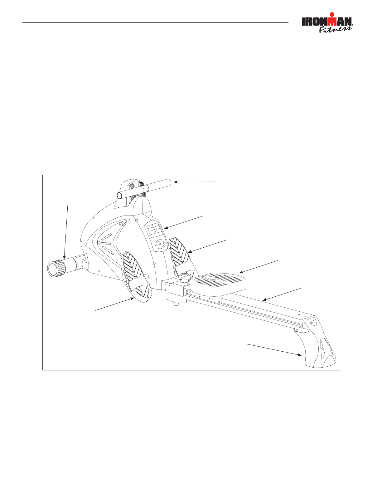
Handle bars
Front Stabilizer
Console
Right Pedal
Seat
Track
Left Pedal
Rear Stabilizer
Getting Started
The Ironman Fitness Power 10 Magnetic Rower will require some assembly.
Unpack the box in a clear area. Remove packing material. Do not dispose of packing
material until assembly is complete and unit is working properly. Place the unit on a
clean level surface for assembly. Make sure there is easy access to an electrical outlet. Before assembling, the unit should be placed as close as possible to its nal location. If you are missing any parts, please call Ironman Fitness at 1-800-750-4766.
Tools have been provided to assist with product assembly.
4
(A1)Main Frame
(A2) Front Stabilizer
(A4)Upper Slide Track
(B9)Saddle Set
(10) Screw
(C1) Knob
(A1)Main Frame
(A2) Front Stabilizer
(B9)Saddle Set
(A2) Front Stabilizer
(A4)Upper Slide Track
(B9)Saddle Set
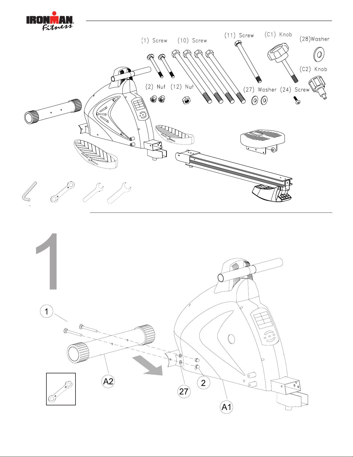
Parts Identier
(1) Vis
(10) Vis
(24) Vis
(11) Vis
(2) Écrou
(12) Écrou
(27) Rondelle
(C2) Molette
(C1) Molette
(27) Rondelle
Étapes de montage
(A2) Stabilisateur avant
(B9) Ensemble-selle
(A2) Stabilisateur avant
(B3-1) Pédale gauche
(B3) Pédale droite
(A2) Front Stabilizer
(A4)Upper Slide Track
(B9)Saddle Set
(B9)Saddle Set
B9) Selle
(A4) Glissière supérieure
Identificateur de pièces
Petites pièces agrandies aux fins d’illustration
Outil
6mm
13/14mm
14mm 21mm
(1) Vis
(10) Vis
(24) Vis
(11) Vis
(2) Écrou
(12) Écrou
(27) Rondelle
(C2) Molette
(C1) Molette
(27) Rondelle
Étapes de montage
(A2) Stabilisateur avant
(B9) Ensemble-selle
(B3) Pédale droite
(A2) Front Stabilizer
(A4)Upper Slide Track
(B9)Saddle Set
(B9)Saddle Set
B9) Selle
(A4) Glissière supérieure
Petites pièces agrandies aux fins d’illustration
Outil
13/14mm
14mm 21mm
(A2) Front Stabilizer
Assembly Steps
(B3-1) Left Pedal
Assembly Steps
(B3) Right Pedal
(A4) Upper Slide track
Tool
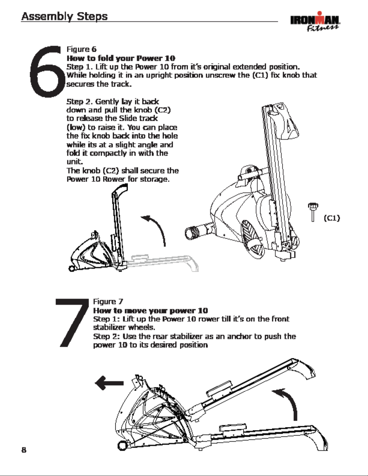
Figure 1
Assembly for front stabilizer with
main frame
Step 1. Secure the front stabilizer (A2)
and main frame (A1) using carriage bolts
(1) & Nuts (2), and Washers (27).
Smaller parts enlarged for view
B9) Seat
5
Assembly Steps
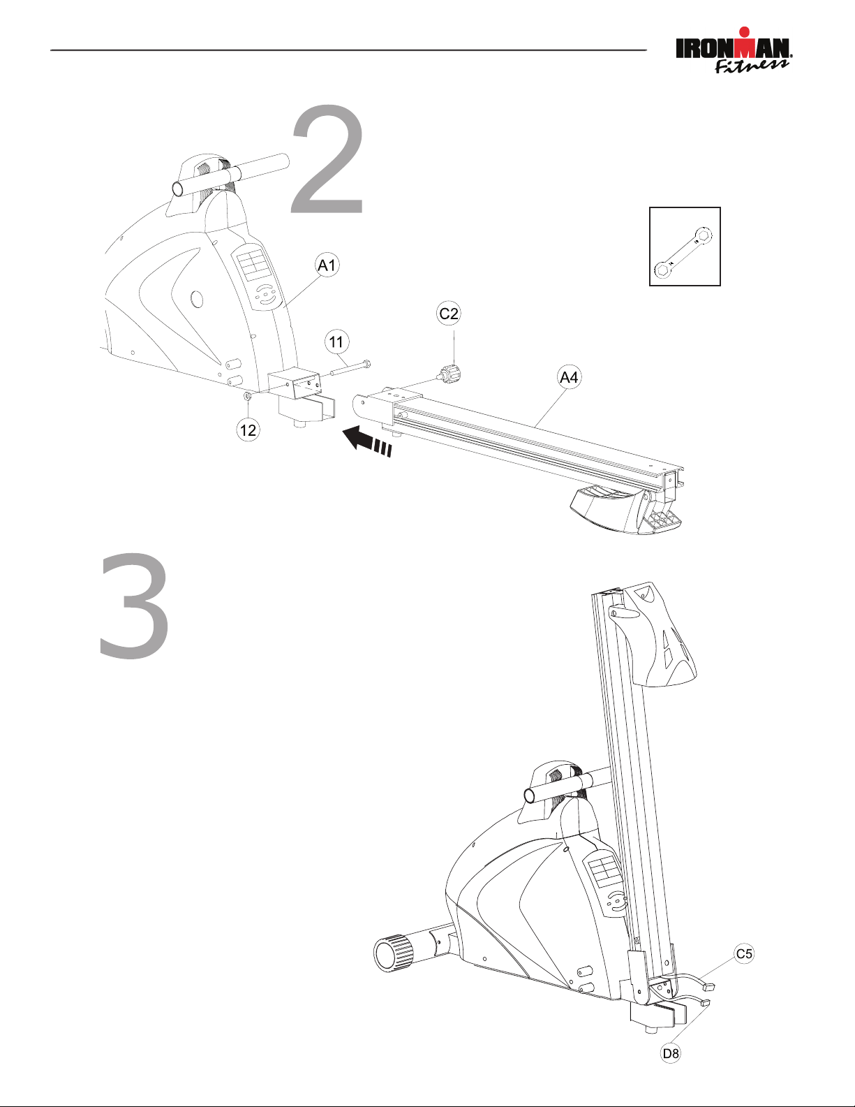
Figure 2
Assembly for upper track
Step 1. Secure main frame (A1) with upper
slide track (A4) using bolt (11), Nut (12) and
tight it by knob (C2).
Figure 3
Assembly for Wireless Pulse Receiver
Step 1. Lift up the Power 10 slide track by pulling out knob (C2). Once the slide track is in
place, release knob (C2) to secure it in the elelvated position.
Step 2. Connect cable (D8) & wireless pulse
receiver (C5).
(1) Vis
(10) Vis
(24) Vis
(11) Vis
(2) Écrou
(12) Écrou
(27) Rondelle
(C2) Molette
(C1) Molette
(27) Rondelle
Étapes de montage
(A2) Stabilisateur avant
(B9) Ensemble-selle
(B3) Pédale droite
(A2) Front Stabilizer
(A4)Upper Slide Track
(B9)Saddle Set
(B9)Saddle Set
B9) Selle
(A4) Glissière supérieure
Petites pièces agrandies aux fins d’illustration
Outil
13/14mm
14mm 21mm
6
7
Assembly Steps
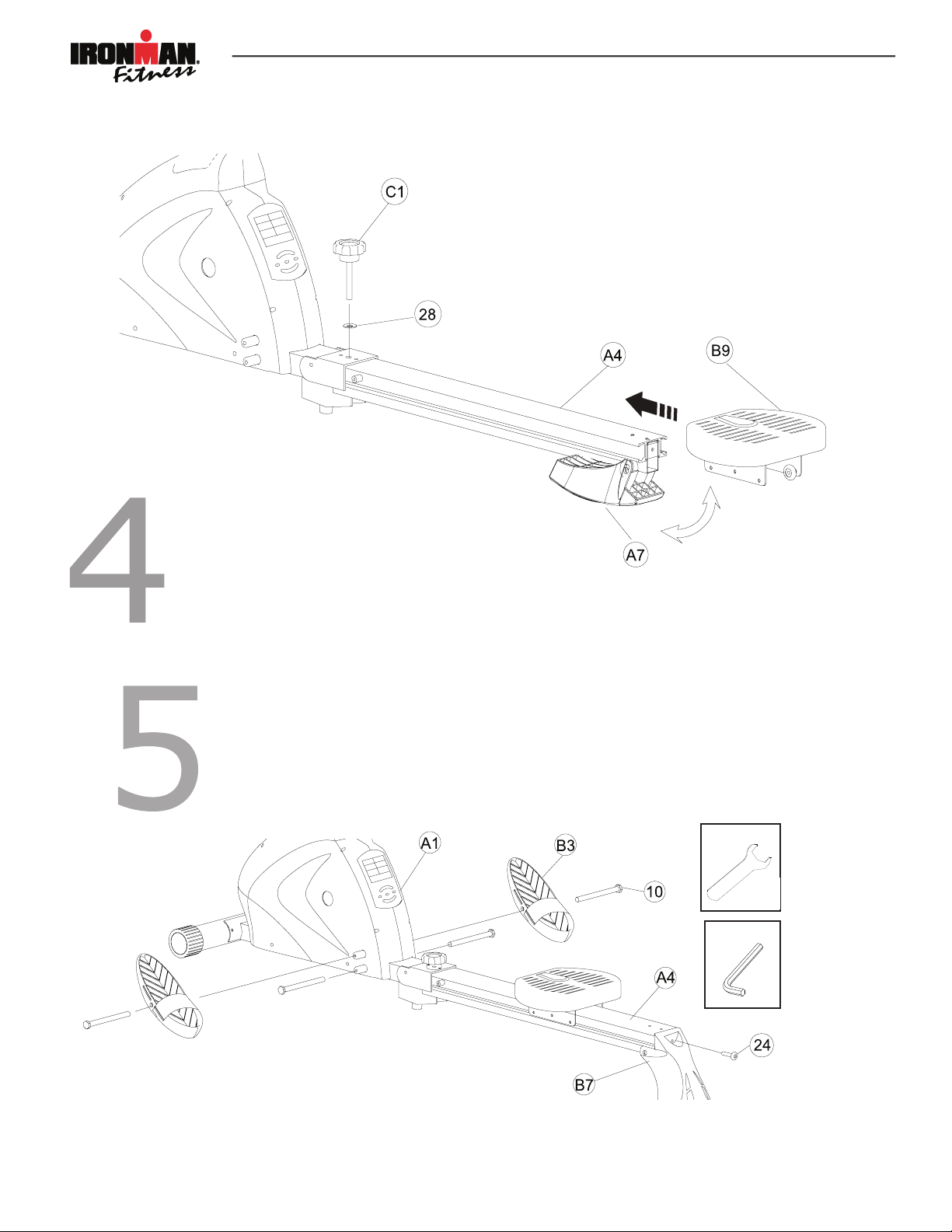
Figure 5
Assembly for pedals
Step 1: Insert shaft bolt (10) into pedal (B3) and secure it
into main frame.
Step 2: Use screw (24) to secure rear stabilizer to slide track.
Figure 4
Assembly for saddle seat with slide track
Step 1. Lower slide track back into place.
Step 2. Equip saddle (B9) into slide track (A4).
Step 3. Fold up rear stabilizer (A7)
Step 4. Secure the knob with (C1) and washer (28).
(1) Vis
(10) Vis
(24) Vis
(11) Vis
(2) Écrou
(12) Écrou
(27) Rondelle
(C2) Molette
(C1) Molette
(27) Rondelle
Étapes de montage
(A2) Stabilisateur avant
(B9) Ensemble-selle
(A2) Stabilisateur avant
(B3-1) Pédale gauche
(B3) Pédale droite
(A2) Front Stabilizer
(A4)Upper Slide Track
(B9)Saddle Set
(B9)Saddle Set
B9) Selle
(A4) Glissière supérieure
Identificateur de pièces
Petites pièces agrandies aux fins d’illustration
Outil
6mm
13/14mm
14mm 21mm
(1) Vis
(10) Vis
(24) Vis
(11) Vis
(2) Écrou
(12) Écrou
(27) Rondelle
(C2) Molette
(C1) Molette
(27) Rondelle
Étapes de montage
(A2) Stabilisateur avant
(B9) Ensemble-selle
(B3) Pédale droite
(A2) Front Stabilizer
(A4)Upper Slide Track
(B9)Saddle Set
(B9)Saddle Set
B9) Selle
(A4) Glissière supérieure
Petites pièces agrandies aux fins d’illustration
Outil
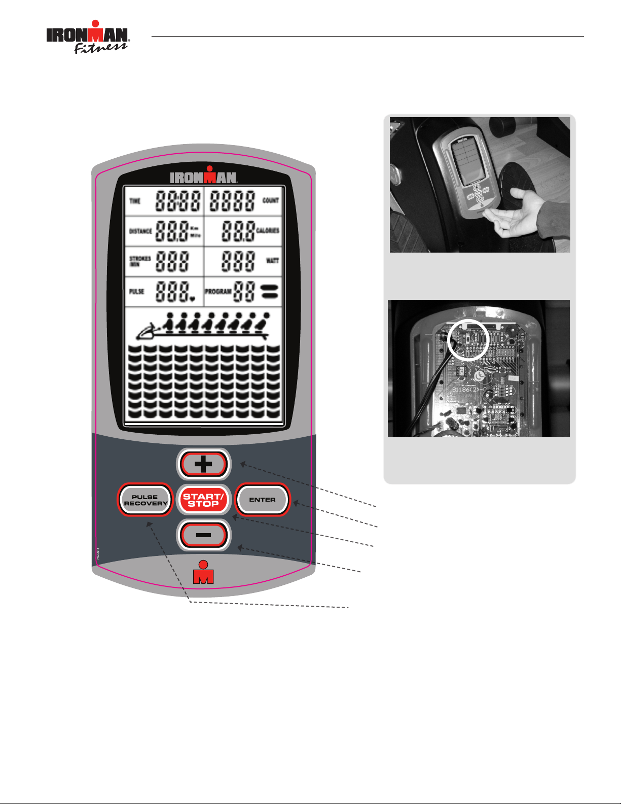
Console Instructions
Console Layout and Design
Take a few moments to review the console layout.
Below is an overview of the console and their different functions.
The miles / kilometer switch is located on the
back of the console. To remove the console,
push in the tab of the lower part
of the console and lift up.
A. Powering Up:
Connect adapter into power source1.
If the connection cables were installed incorrectly, monitor will display “E1” on matrix 2.
display and will generate a long beeping sound. Before asking service, please examine if all
connection cables are well connected and then reset the power to release the beep sound
or press START / STOP (Hold to reset) button to restart system. If the monitor still show
“E1” message, please call service.
If the monitor shows “ E2 ”message, please call service.3.
To change from miles to kilometers and
vice versa, ip the switch highlighted inside
the circle. Once switched, you must restart
the console to activate.
(d) Increase
(c) Enter
(b) Start/Stop
(e) Decrease
(a) Pulse Recovery
9
 Loading...