

Ironman Fitness IM-R7 User Manual
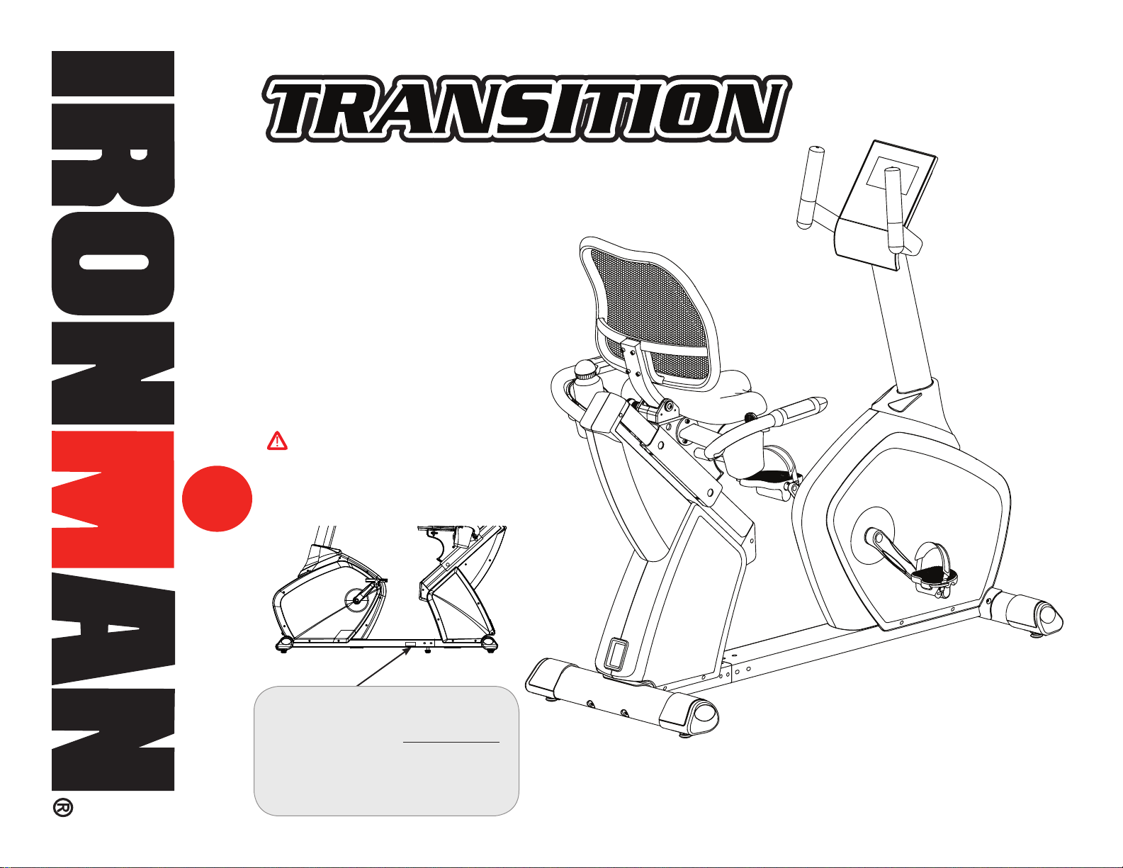
Owner’s Manual
CAUTION
Transition Recumbent Bike
Customer Service
(800) 750-4766
Manufactured By:
Ironman Fitness
4009 Distribution Drive
Suite 250
Garland, TX 75041
Read all precautions and instructions in
this manual before using this equipment.
Model Name : TRANSITION
Serial Number :
Serial Number can be found at
the above specified location.
315-00137
09/17 Rev 5.0
ww w.ironmanfitness.com
TABLE OF CONTENTS
Table of Contents 2
Important Safety Information 3
Assembly 4
Parts Identifier 5
Assembly Steps 7
Console Information 21
Workout Information 28
Parts List 32
Exploded View 34
Warranty 35
Ironman series
oDel: TRANSITIoN
M
QUeSTIoNS?
CAll
(800) 750-4766
Mon day- Friday
8:30am - 5:30 pm Central Time
THANK YOU
THANK YOU for making this unit a part of your exercise program. Ironman
Fitness assures the very best in value, appearance, durability and biomechanics.
This manual will guide you through the assembly process. If at any time you are
having trouble with the assembly or use of this product, then please contact us at
our Ironman Fitness Help line. We have trained service technicians on site to take
care of you, our valued customer.
REGISTRATION CARD
To avoid unnecessary delays in warranty parts and to insure that a permanent record of your purchase is on file with our company, be sure to send in
the warranty registration card or register on-line at www.ironmanfitness.com
within 10 days of purchase..
2 Table of Contents

ww w.ironmanfitness.com
WARNING! Before using this unit or starting any exercise program, consult your
physician. This is especially important for persons over the age of 35 and/or persons with pre-existing health problems. The manufacturer or distributor assumes no
responsibility for personal injury or property damage sustained by or through the use of this product.
burns, re, or other possible injuries to the user, it is important to review this manual and the following precautions before operation.
To reduce the risk of electrical shock,
SAFETY PRECAUTIONS AND TIPS
1. It is the owner’s responsibility to ensure that all users of this unit have read the owner’s Manual and are familiar with warnings and
safety precautions.
2. This unit has a user maximum capacity of 300 pounds.
3. The unit should only be used on a level surface and is intended for indoor use only. The unit should not
be placed in a garage, patio, or near water and should never be used while you are wet. Ironman Fitness recommends a
mat be placed under the unit to protect oor or carpet and for easier cleaning.
4. Follow safety information in regards to plugging in your unit. Do not run the power cord underneath your
unit. Do not operate the unit with a damaged or frayed power cord.
5. Wear comfortable, good-quality walking or running shoes and appropriate clothing. Do not use the unit with bare feet, sandals,
socks or stockings.
6. Always examine your unit before using to ensure all parts are in working order.
7. Allow the unit to fully stop before dismounting.
8. Pets should never be allowed near the unit.
9. Do not leave children unsupervised near or on the unit.
10. Never operate the unit where oxygen is being administered, or where aerosol products are being used.
11. Never insert any object or body parts into any opening.
12. For safety and to prevent damage to your unit, no more than one person should use the unit at a time.
13. Always unplug the unit before cleaning and/or servicing. Service to your unit should only be performed by an authorized service
representative, unless authorized and/or instructed by the manufacturer.
14. Failure to follow these instructions will void the unit warranty.
Thank you for purchasing the Ironman Fitness Transition! The quality product you have chosen was designed to meet your needs for
cardiovascular exercise. Before you start, please read the owner’s Manual and become familiar with the operation of your new unit. Remember to take time to perform stretching exercises, provided in this manual, to help avoid injury. If you are taking medication, consult your
physician to see what effect the medication will have on your exercise heart rate. If you have heart problems, you are not active, and/or
are over the age of 35 years, do not use the pre-set programs or start an exercise program without rst contacting and receiving approval
from your physician. To avoid the risk of electrical shock, always keep the console dry. Do not spill liquids on the console. Ironman Fitness
recommends a sealed water bottle for beverages consumed while using the unit.
Important Safety Information
3

Assembly
ww w.ironmanfitness.com
ww w.ironmanfitness.com
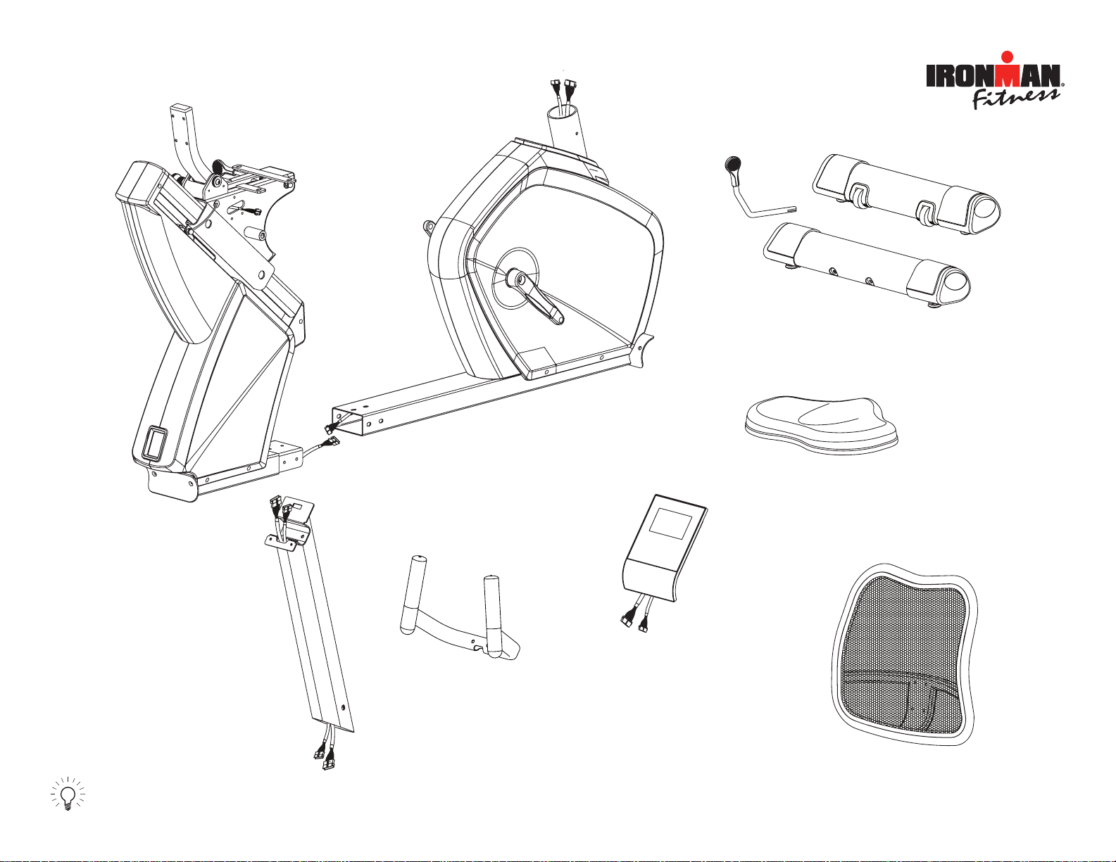
Front Main Frame
A1
Rear Main Frame
A2
Seat Slide
Adjustment Handle
A11
C
Front
Stabilizer
Rear
Stabilizer
B
D
Upright Post
E
Upright Handlebar
F
Console
G
Seat Pad
H
Back Rest
Prior to assembly, remove components from the box and verify
that all the listed parts were supplied.
5Parts Identifier
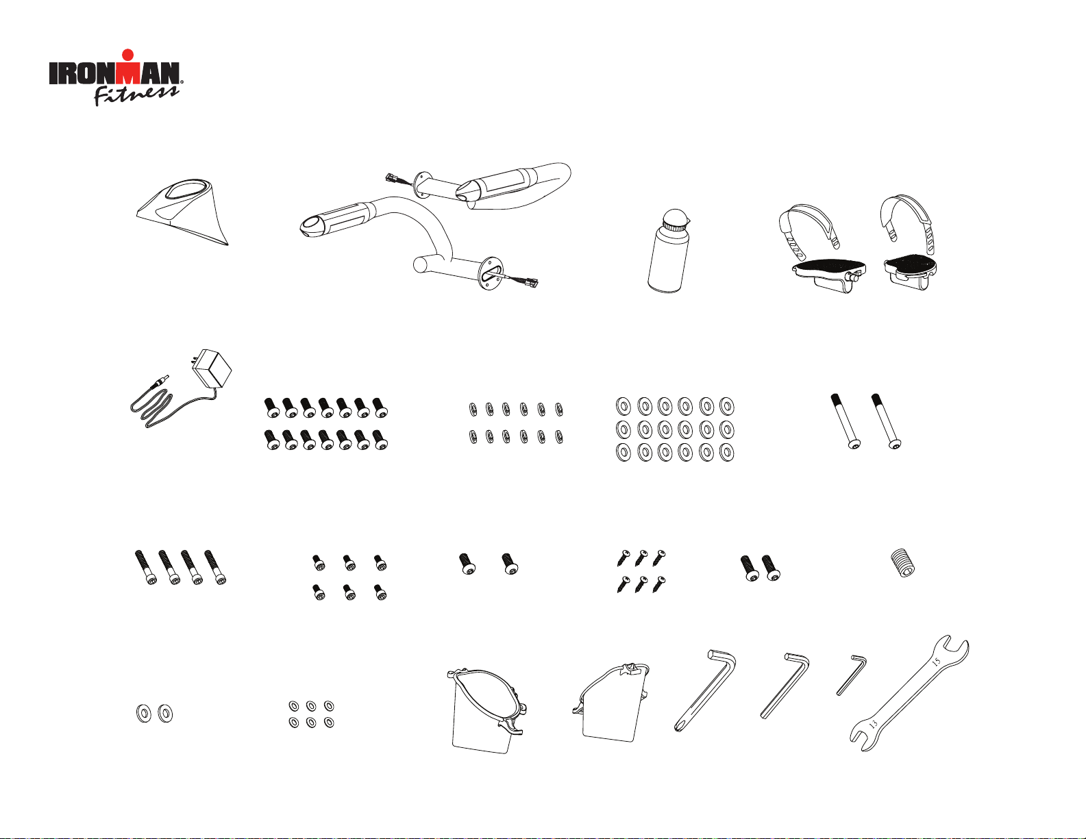
M
Adapter
I
Upright Post
Cover
K
Water Bottle
N1
Tools
J-L
J-R
Side Handlebar - Right
Side Handlebar - Left
L-L
L-R
Pedal - Left
Pedal - Right
N2
N3
N4
N5
N6
N7
N8
N9
Allen Screws M8*15
Spring Washers M8
Flat Washers M8
Allen Screws M8*105
Allen Screws 1/4” *40
Allen Screws M6*12
Allen Screws M8*20
Screws M4*15
Allen Screws
(Black)M8*35
Set Screw M6*8
Flat Washers (Black) M8
Oval Washers 8*4.5
N10
N11
N12
Accessory Tray - Left
Accessory Tray - Right
R1
R2
6mm
5mm 3mm
13mm
15mm
ww w.ironmanfitness.com
Important Information
Parts Identifier
6
A1
B
N7
N2
N3
ww w.ironmanfitness.com
Use Tool
6mm
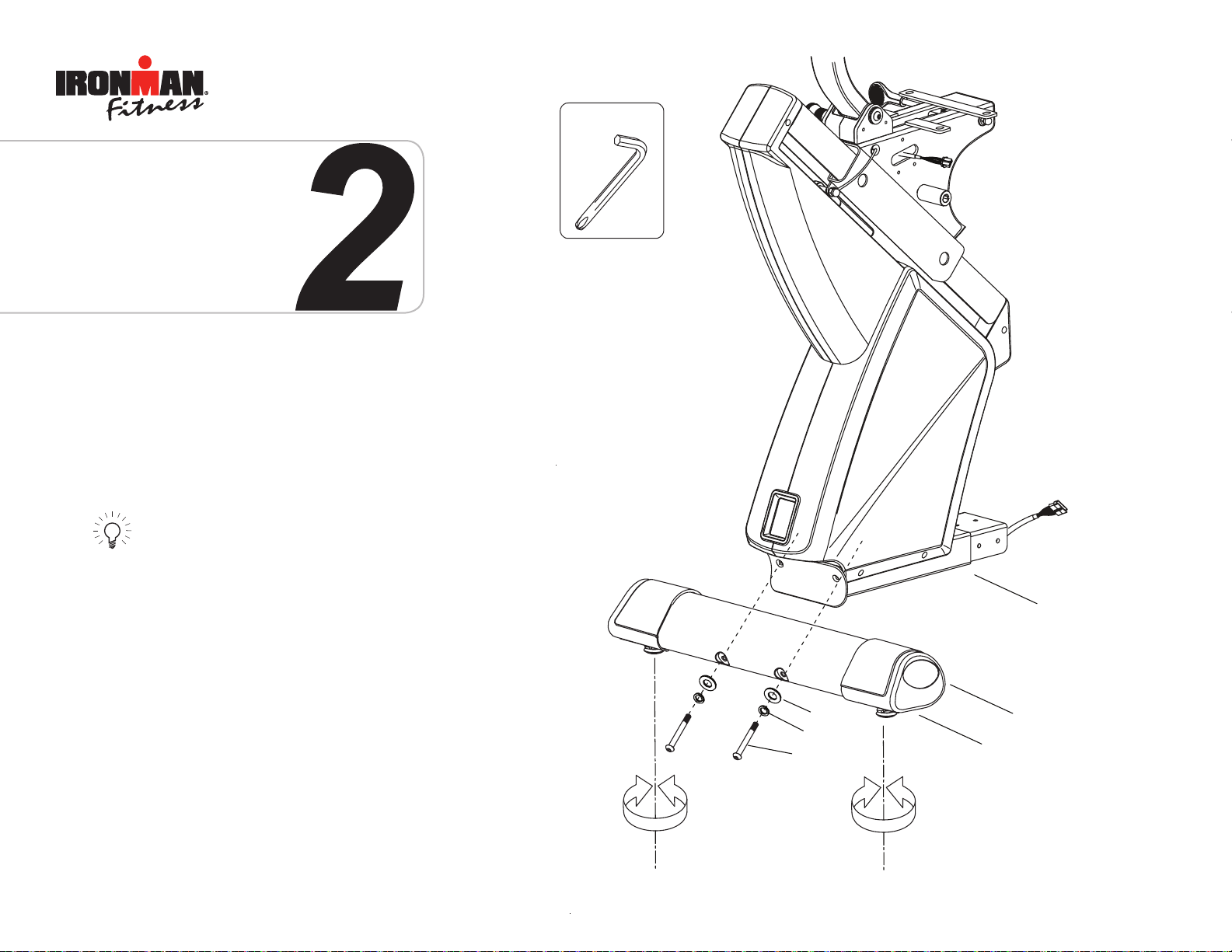
1
ASSEMBLY FOR FRONT STABILIZER
Secure the front stabilizer (B) to the front main
frame (A1) using 2 screws (N7), 2 spring washers
(N2) and 2 flat washers (N3).
Note: Front stabilizer (B) is very similar to rear
stabilizer (C) but contains transport wheels.
Make sure not to get them mixed up.
Assembly
7
ww w.ironmanfitness.com
A2
N4
C
C1
N2
N3
Use Tool
6mm
ASSEMBLY FOR REAR STABILIZER
Secure the rear stabilizer (C) to the rear main frame
(A2) using two screws (N4), 2 spring washers (N2)
and 2 flat washers (N3).
Note:
After you finish the assembly for front and rear
stabilizer bars in order to add stability to the
unit, you may need to adjust the levelers that
are located on the bottom of the unit.
8
Assembly
ww w.ironmanfitness.com
A1
A2
N1
N2
N3
A3
A4
Use Tool
6mm
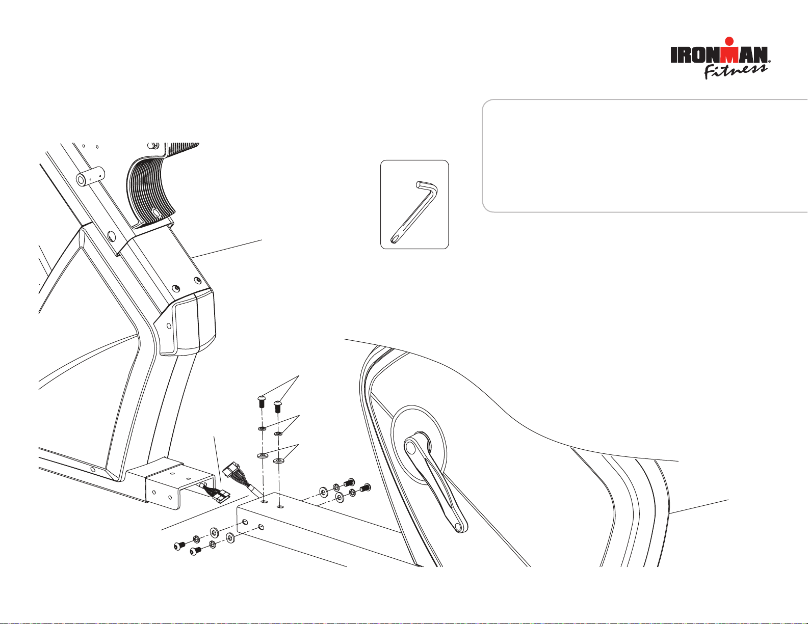
3
ASSEMBLY FOR FRONT & REAR MAIN FRAME
Step 1:
Connect the front (A4) and rear (A3) pulse wires together.
Step 2:
Attach front (A1) and rear (A2) main frames together, making sure all wires are lined up correctly so that they are not
pinched when assembling the two frames together. Then,
secure them using 6 allen screws (N1), 6 spring washers
(N2) and 6 at washers (N3).
Important Information 9
Assembly
ww w.ironmanfitness.com
A1
I
D
N1
N2
N3
A33
A34
A4
A36
I
Use Tool
6mm
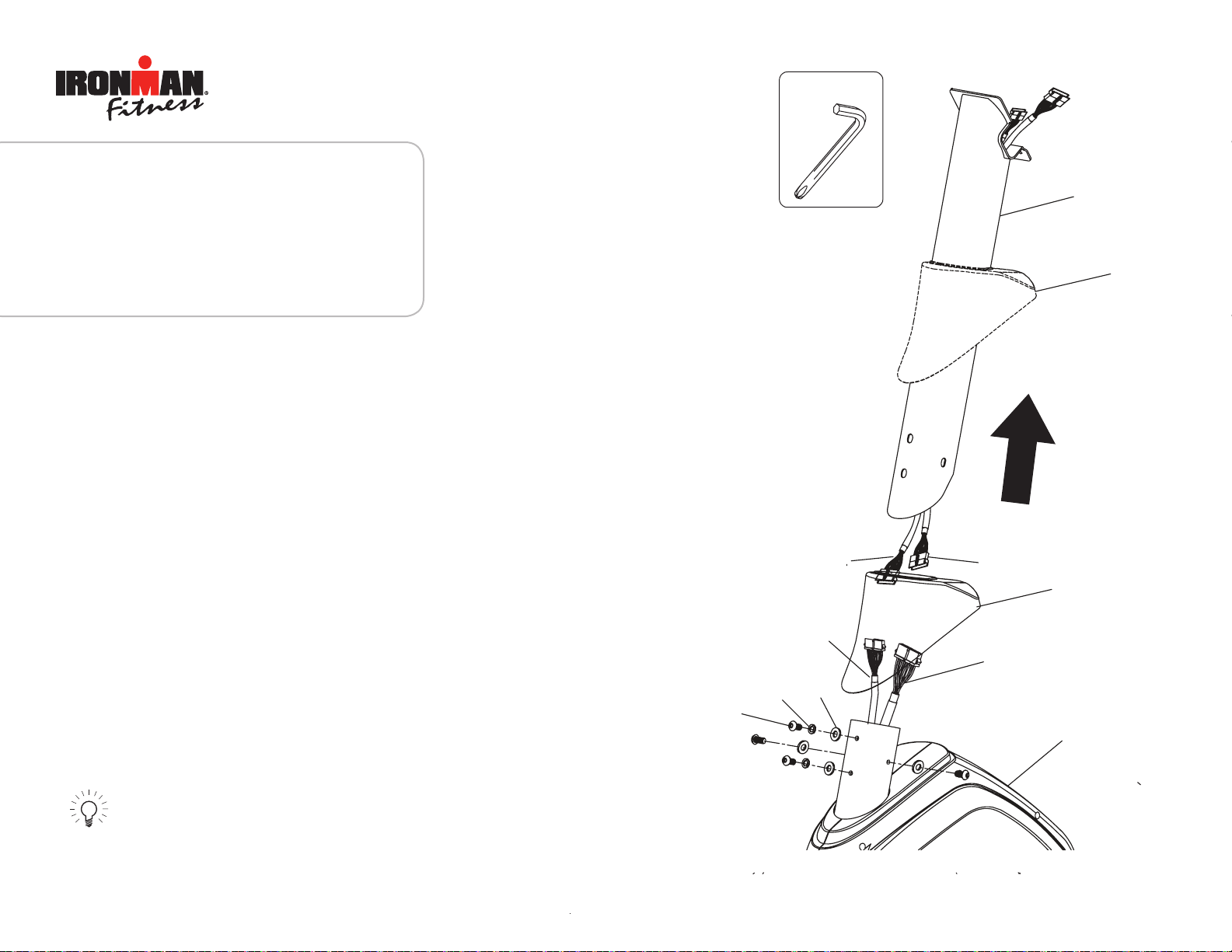
4
ASSEMBLY FOR UPRIGHT POST
Step 1:
Insert the upright post cover (I) to the upright post (D) from the
bottom side.
Step 2:
Connect the lower pulse wire (A4) with the upper pulse wire
(A33). Also, connect the lower sensor wire (A36) with the upper
sensor wire (A34).
Step 3:
Attach upright post (D) to the front main frame (A1). Secure with
4 allen screws (N1), 4 spring washers (N2) and 4 flat washers
(N3).
Step 4:
Slide the upright tube cover (D) down to conceal tube connection.
Note:
Be careful not to pinch the sensor wire connection
during assembly.
10 Important InformationAssembly
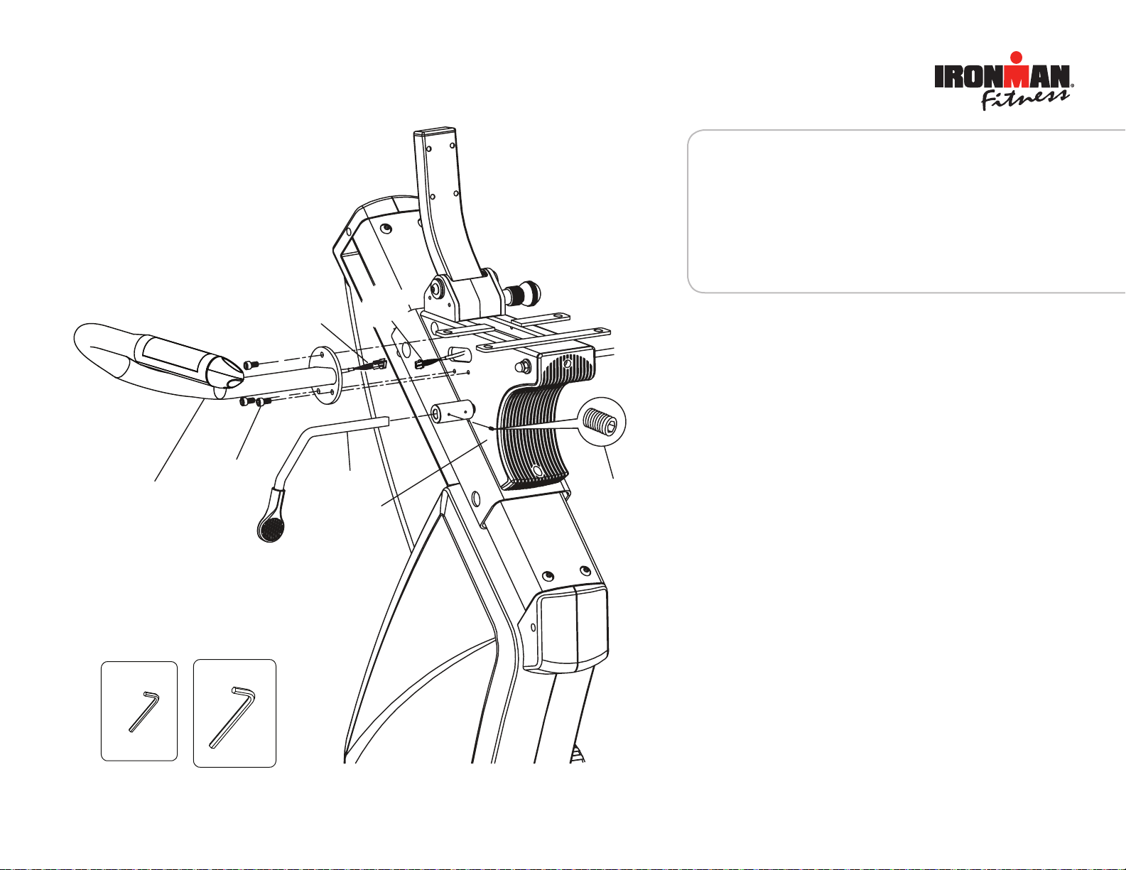
N6
A9
N10
A38
A11
J-R
J1
Use Tool
3mm
Use Tool
5mm
ww w.ironmanfitness.com
5
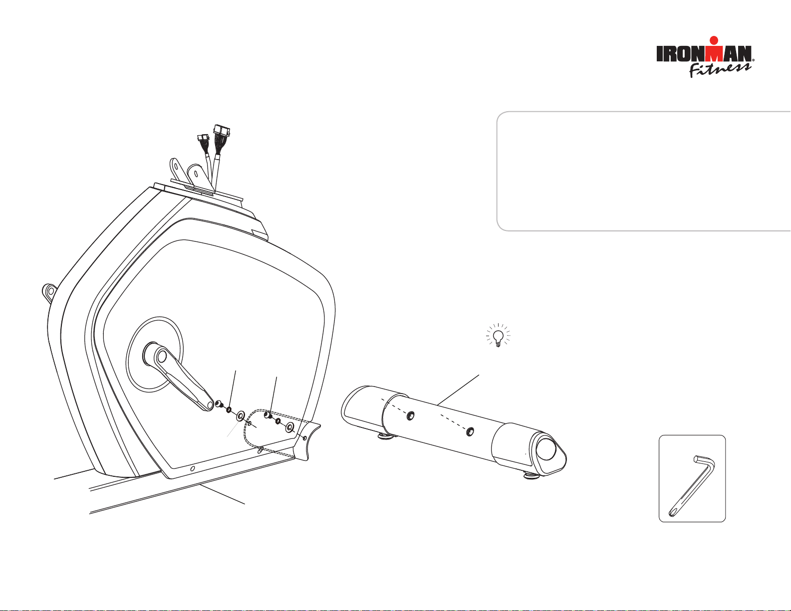
ASSEMBLY FOR SEAT SLIDE ADJUSTMENT
Insert the seat slide adjustment handle (A11) into the
seat slide adjsutment collar on the seat slide assembly (A9). Secure it with M6 set screw (N10).
ASSEMBLY FOR RIGHT HANDLEBAR
Step 1:
Connect pulse wire (J1) and pulse wire (A3).
Step 2:
Mount the right handlebar (J-R), to the seat slide
assembly (A9) and secure with 3 allen screws
(N6).
Important Information 11Assembly
 Loading...