

Page 1
Owner’s Manual
Ironman 125e Elliptical
Customer Service
1.800.750.IRON
1.800.750.4766
4009 Distribution Drive
Suite 250
Garland, TX 75041
www.ironmanfitness.com
CAUTION! Read all precautions
and instructions in this manual
before using this equipment.
Model Name : 125E
Serial Number :
315-00123
Rev A 10/07
Write down for future reference
Serial Number Decal Location
Page 2

Table of Contents
Important Safety Information 3
Parts Identifier 5
Assembly 7
Console Instructions 11
Monitoring Your Heart Rate 14
Moving Instructions 16
Warm-Up Exercises 17
Parts List 20
Exploded View 21
Warranty Information 22
2
Page 3

Important Safety Information
WARNING! Before using this unit or starting any exercise program, consult your physician.
This is especially important for persons over the age of 35 and/or persons with pre-existing
health problems. The manufacturer or distributor assumes no responsibility for personal injury
or property damage sustained by or through the use of this product.
SAFETY PRECAUTIONS AND TIPS
1. It is the owner's responsibility to ensure that all users of this unit have read the Owner's
Manual and are familiar with warnings and safety precautions.
2. This unit has a user maximum capacity of 250 pounds.
3. The unit should only be used on a level surface and is intended for indoor use only. The unit
should not be placed in a garage, patio, or near water and should never be used while you
are wet. Ironman Fitness recommends a mat be placed under the unit to protect floor or
carpet and for easier cleaning.
4. Wear comfortable, good-quality walking or running shoes and appropriate clothing. Do not
use the unit with bare feet, sandals, socks or stockings.
5. Always examine your unit before using to ensure all parts are in working order.
6. Allow the unit to fully stop before dismounting.
7. Pets should never be allowed near the unit.
8. Do not leave children unsupervised near or on the unit.
9. Never operate the unit where oxygen is being administered, or where aerosol products are
being used.
10. Never insert any object or body parts into any opening.
11. For safety and to prevent damage to your unit, no more than one person should use the
unit at a time.
12. Service to your unit should only be performed by an authorized service representative,
unless authorized and/or instructed by the manufacturer.
13. Failure to follow these instructions will void the unit warranty.
3
Page 4
Before You Start
Thank you for purchasing the Ironman 125E Elliptical! This quality product you have chosen
was designed to meet your needs for cardiovascular exercise. Before you start, please read the
Owner's Manual and become familiar with the operation of your new unit.
Remember to take the time to perform the stretching exercises provided to avoid
injury.
If you are taking medication, consult your physician to see if the medication will affect your exercise heart rate.
If you have heart problems, you are not active, and/or are over the age of 35 years, do not use
the pre-set programs or start an exercise program without first contacting and receiving approval
from your physician.
To avoid the risk of electrical shock, always keep the console dry. Do not spill liquids on the console. Ironman Fitness recommends a sealed water bottle for beverages consumed while using
the unit.
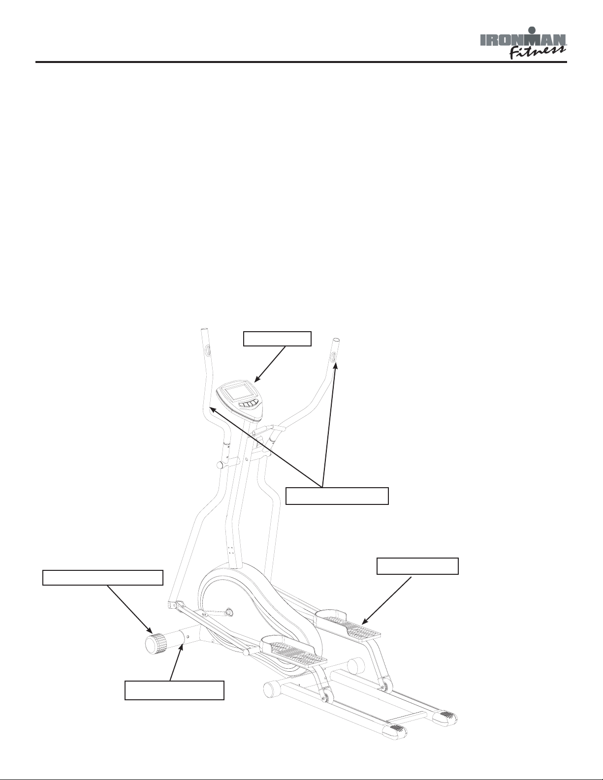
Please review the following drawing below to familiarize yourself with the listed
parts.
Console
Transport Wheels
Front Stabilizer
Pulse Handlebar
Foot Pedals
4
Page 5

Assembly
19
10x13x14x15x17x19 Screw Driver
M5 Allen Wrench
14
13
10
15
8X19 Arc Washer(34)-12
10*26*2.0 Washer(48)-4
6*13*1.0 Washer(63)-4
M8x15 Screw (65)-8
M6 cap nut(64)-4
M6X40mm Carriage Bolt(62)-4
3/8" Nylon Locknut(49)-4
M8X70mm Carriage Bolt(35)-4
3/8" Nylon Locknut(47)-4
M8 Cap Nut(33)-4
M5 Allen Wrench
INSTRUCTIONS FOR ASSEMBLY:
Unpack the box in a clear area. Check to make sure all components are present and in good
condition. Do not dispose of the packing material until the assembly is completed. Tools have
been provided for you to use when assembling this product.
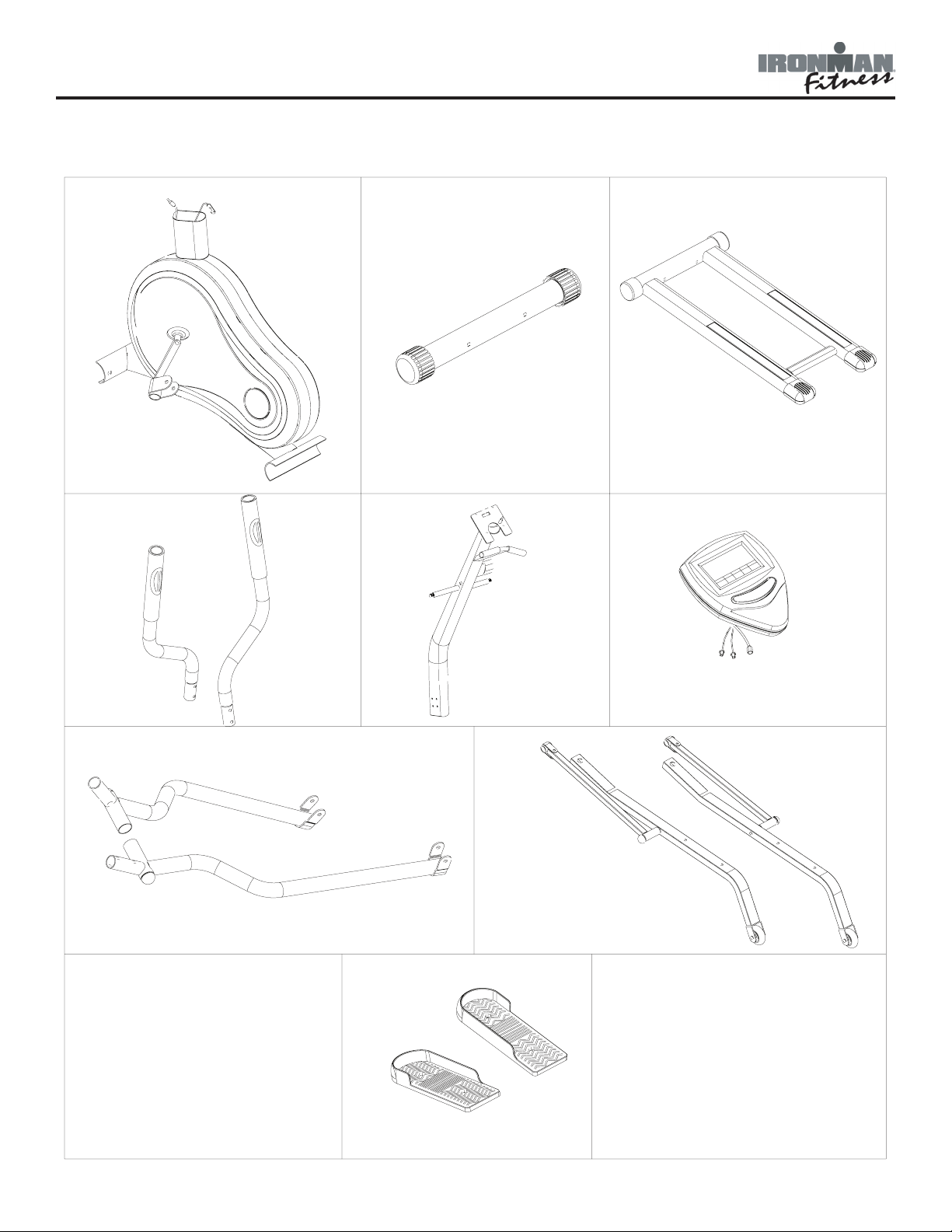
Locate the hardware pack and identify the following parts required for assembly.
5
Page 6
Assembly
9
7
4 6
8
5
1
32
Assembly Part Identier
6
Page 7
Assembly
2
34
33
33
34
35
54
33
34
35
1
34
33
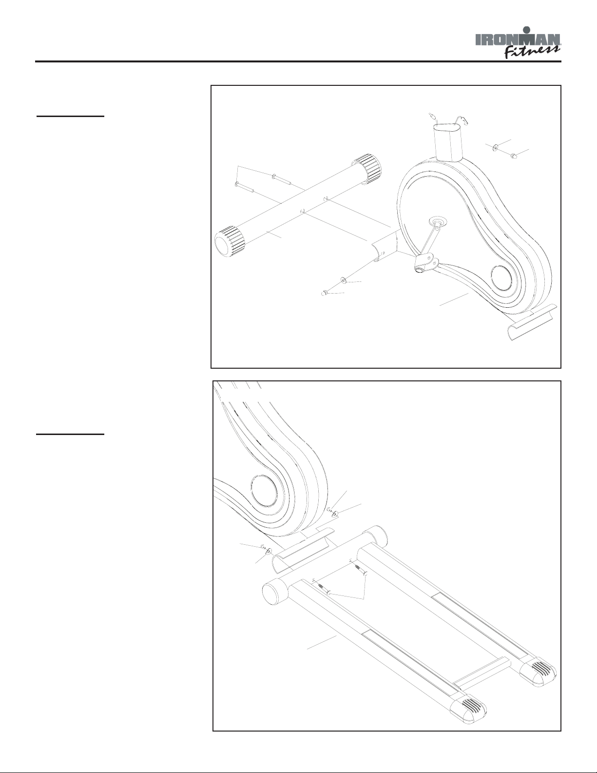
FIGURE 1
Step 1:
Attach the Front Stabilizer (54)
onto Main Frame (1) with the
carriage screws (35), cap nuts
(33), and arc washers (34).
Figure 1
FIGURE 2
Step 1:
Attach the rear frame
w/aluminum rails (2) to the
main frame (1) and secure it
with carriage bolts (35), arc
washers (34) and cap nuts
(33).
Figure 2
7
Page 8
Assembly
48
49
48
49
50
4a
5a
47
72
66
3
73
34
68
65
34
65
66
68
4A
68
4B
66
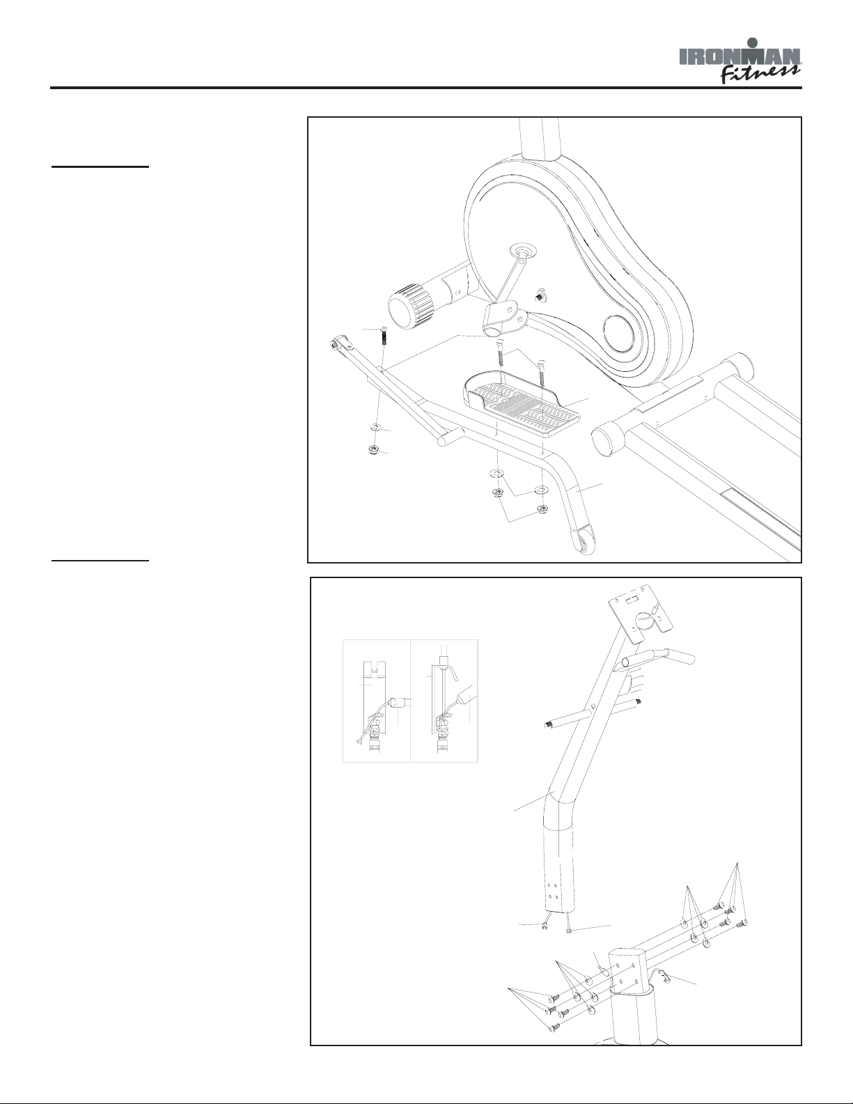
FIGURE 3
Step 1:
Secure left pedal (5a) to left
pedal tube (4a) with screws
(47), nylock nuts (49) and
washers (48). Then secure left
pedal tube (4a) to unit by lining up the pedal tube to the
axle with screws (50), nylock
nuts (49) and washer (48).
Repeat on right side.
Figure 3
FIGURE 4
Step 1:
Connect the extension wires
(72) to the sensor Wires (73);
Connect the tension cable (68)
to the tension controller (66) as
following steps 2-3:
Step 2:
Put the cable end (66) into the
spring hook (68). Refer to figure 4A.
Step 3:
Pull the knob and insert the
short cable (66) into the gap of
the bracket (68) Refer to figure
4B.
Tension is increased by turning
the knob clockwise.
Figure 4
Step 4:
Secure the upright post (3)
onto Main Frame (1) with
Washers (34) and Screws (65).
8
Page 9

Assembly
40
27
36
71
6a
7a
63
46
62
64
45
44
6b
7b
87
42
3
67
85
88
9
72
69
3
FIGURE 5
Step 1:
Install the left sleeve (6a) to
the axle on the upright tube
(3) and secure with washer
(46), nut (45), and nut cap
(44). Connect the pulse wire
(42) with the pulse wire (87).
Connect pulse wire (88) to
the second connector on the
pulse wire (87). Connect
the upper handlebar (7a)
to the lower left handlebar
(6a) with carriage bolts (62),
washers (63) and cap nuts
(64). Attach the pedal tube
to the lower left handlebar
(6a) with nut caps (67).
Finally, insert plastic cap (85)
into the opening as shown.
Repeat on right side.
Figure 5
FIGURE 6
Step 1:
Connect the sensor wire (72)
and the pulse wires to the console (9). Attach the console
(9) to the top of the upright
tube (3) and secure it using
screws (69) attached to the
console.
Figure 6
9
Page 10

Assembly
Congratulations!
You have completed assembly of your new 125E Elliptical!
10
Page 11

Console Overview
CONSOLE BUTTONS
ENTER/RESET:
Used to enter edit mode for a setting when using target training. If held for over 3 seconds,
will reset console, and change all of the settings back to 0.
PULSE RECOVERY:
Used to enter "Pulse Recovery" mode during workout. This will begin the fitness test. Fitness
Test is described in more detail in the following pages.
DOWN and UP:
Use to select which setting will be edited. When editing setting, use to scroll up or down until
selected setting is found.
CONSOLE FUNCTIONS
TIME:
Count up - No preset target, Time will count up from 00:00 to maximum 99:59 with each
increment is 1 second. Count down - If training with preset Time, Time will count down from
preset to 00:00. Each preset increment or decrement is 1 minute between 1:00 to 99:00.
11
Page 12

Console Overview
SPEED:
Display current training speed from 0.0 to maximum 99.9 MPH.
DISTANCE:
Count up - No preset target, Distance will count up from 0.00 to maximum 99.90 with each
Increment 0.1 MPH. Count down - If training with preset target, Distance will count down from
preset to 0.00. Each preset increment or decrement is 0.1 MPH between 0.00 to 99.90.
CALORIES:
Count up - No preset target, Calories will count up from 0 to maximum 990 with each 1 cal
increment. Count down - If training with preset target, Calories will count down from preset
calorie to 0. Each preset increment or decrement is 10 cal from 0 to 990 cal.
PULSE:
Displays your current heart beat figures as soon as both hands are holding the pulse sensor.
The console will detect your heart rate through hand grip sensors.
PULSE RECOVERY:
After exercising for a period of time, keep holding on to the handgrips and press the “PULSE
RECOVERY” button. Screen will display your heart rate recovery status with the F1, F2 to F6.
F1 is the best, F6 is the worst. User may keep exercising to improve the heart rate recovery
status (Press the RECOVERY button again to return to the main display).
GENERAL INFORMATION
1. Start pedaling or press any button to start Console.
2. The Console will shut down after 4 minutes of no activity. Note: Values will be reset to zero.
3. To Reset Console press and hold the ENTER/RESET button for 5 seconds.
Note: The values calculated or measured by the console are for exercise purposes only, not for
medical purposes.
4. Console uses two standard AA batteries. To install, remove battery cover located behind con-
sole. Replace battery cover when finished installing new batteries.
GETTING STARTED:
Quick Start:
Turn console on by pedaling or pressing any button. To begin working out without setting any
targets, start pedaling. The time will begin to count up.
Target Workout:
Turn console on by pedaling or pressing any button. Using the "Up" and "Down" buttons,
select the setting you wish to set first (Time, Cal, Pulse), press "Enter/Reset" when ready to
edit. The current setting will flash. Use the "Up" and "Down" buttons until desired setting
is reached. Press "Enter/Reset" move to next setting. When all desired settings have been
entered, start pedaling to begin workout.
12
Page 13

Console Overview
FITNESS TEST: (Pulse Recovery Feature)
The fitness test compares your pulse rate before and after training. You will notice that your
fitness will improve with regular exercise.
Press the PULSE RECOVERY button immediately after your workout. Grasp the Pulse Grips.
Timer will count down from 60 seconds. Your personal fitness will display on the screen.
(F1-F6)
F1 = Excellent
F2 = Good
F3 = Fair
F4 = Below Average
F5 = Poor
F6 = Very Poor
13
Page 14

Monitoring Your Heart Rate
Monitoring Your Heart Rate
To obtain the greatest cardiovascular benefits from your exercise workout, it is important to
work within your target heart rate zone. The American Heart Association (AHA) defines this target as 60%-75% percent of your maximum heart rate.
Your maximum heart rate may be roughly calculated by subtracting your age from 220. Your
maximum heart rate and aerobic capacity naturally decreases as you age. This may vary from
one person to another, but use this number to find your approximate effective target zone. For
example, the maximum heart rate for an average 40 year-old is 180 bpm. The target heart
rate zone is 60%-75% of 180 or 108-135 bpm. See Fitness Safety below.
Before beginning your workout, check your normal resting heart rate. Place your fingers lightly
against your neck, or against your wrist over the main artery. After finding your pulse, count
the number of beats in 10 seconds. Multiply the number of beats by six to determine your
pulse rate per minute. We recommend taking your heart rate at these times; at rest, after
warming up, during your workout and two minutes into your cool down, to accurately track
your progress as it relates to better fitness.
During your first several months of exercising, the AHA recommends aiming for the lower part
of the target heart rate zone-60%, then gradually progressing up to 75%.
According to the AHA, exercising above 75% of your maximum heart rate may be too strenuous unless you are in top physical condition. Exercising below 60% of your maximum will result
in minimal cardiovascular conditioning.
Check your pulse recovery rate – If your pulse is over 100 bpm five minutes after you stop
exercising, or if it’s higher than normal the morning after exercising, your exertion may have
been too strenuous for your current fitness level. Rest and reduce the intensity next time.
Fitness Safety The target heart rate chart indicates average rate zones for different ages. A
variety of different factors (including medication, emotional state, temperature and other conditions) can affect the target heart rate zone that is best for you. Your physician or health care
professional can help you determine the exercise intensity that is appropriate for your age and
condition.
(MHR) = Maximum Heart Rate
(THR) = Target Heart Rate
220 - age = maximum heart rate (MHZ)
MHZ x .60 = 60% of your maximum heart rate.
MHZ x .75 = 75% of your maximum heart rate.
For example, if you are 30 years old, your calculations will be as
follows:
220 - 30 = 190
190 x .60 = 114 (low end or 60% of MHZ)
190 x .75 = 142 (high end or 75% of MHZ)
30 year-old (THR) Target Heart Rate would be 114-142
See Heart Rate Table (on next page) for additional calculations.
14
Page 15

Monitoring Your Heart Rate
TARGET HEART RATE ZONE
100%
Serious
athletic
training range
85%
Cardiovascular
conditioning
range
75%
Fat burning
range
60%
200
170
150
120
195
166
146
117
190
162
143
114
185
157
139
111
180
153
135
108
175
149
131
105
170
145
128
102
165
140
124
99
160
136
120
96
155
132
116
93
20 25 30 35 40 45 50 55 60 65
AGE
15
Page 16

Moving Instructions
CAUTION! TO REDUCE THE POSSIBILITY OF INJURY WHILE LIFTING, BEND YOUR LEGS AND
KEEP YOUR BACK STRAIGHT. AS YOU LEAN THE UNIT, LIFT USING YOUR LEGS, NOT YOUR
BACK.
First, kneel down and grasp the rear support tube with both hands as shown in Figure 1. Next,
with a firm grasp on rear support tube stand up bringing the rear of the bike up in the air and
tilt the unit until it rolls freely on the transport wheels. Using extreme caution, move the unit to
the desired location as shown in Figure 2. Do not attempt to move the unit over an uneven or
rough surface.
Note: The unit you purchased may not be identical to the one pictured.
Note: This unit may not be identical to your unit.
16
Page 17

Warm Up Exercises
EXERCISE GUIDELINES
WARNING! Before beginning this or any exercise program, you should consult your physician.
This is especially important for individuals over the age of 35 or individuals with pre-existing
health problems.
Flexibility is a key to fitness. Stretch all major muscle groups at least two to three times per
week after a 5 to 10 minute warmup. Stretch just to the point of a gentle tug. If you have
back, joint, or other health problems, talk to your doctor first.
Prone on Elbows
Lie on your stomach with
your feet together. Rest
on your forearms with your
elbows directly under your
shoulders. Relax lower back
and abdomen into oor. Hold
for 30-60 seconds or until
muscles feel looser.
Supline Lumbar Rotation
Lie on your back with your
knees bent. Keeping your
knees together and your shoul-
ders against the oor, roll your
knees to one side until you feel
a stretch in your back or hip.
Hold for 30-60 seconds or until
muscles feel looser. Repeat on
opposite side.
Knees to Chest
Lie on your back. Bend your
knees, and lift your feet off the
oor. Grasp your knees with
your arms and pull your knees
toward your chest. Hold for 20
seconds. Repeat three to ve
times.
Cat and Camel
Rest on your hands and
knees. Round your back by
contracting your abdominal
muscles and tucking in your
pelvis; hold for ve seconds.
Then allow your back to sag
toward the oor as you lift
your chest and head; hold
for ve seconds. Repeat the
combination 10 times
Cervical Side Bends
Tilt your head gently toward
one shoulder, keeping your
shoulders level and your face
pointed straight ahead. Hold
for ve seconds, then tilt your
head toward the other shoulder
and hold for ve seconds. Repeat ve times on each side.
Shoulder Circles
In a smooth, continuous motion, make a circle with your
shoulders: Raise them up
towards your ears, pull them
together behind you, lower
them to a resting position,
then roll them forward. Repeat
10 times.
17
Page 18

Wrist Extensor
Extend your right arm in front
of you with your palm up and
your elbow straight. Point
your ngertips toward the
oor by bending at the wrist.
Using your left hand, pull the
back of your right hand to-
ward you gently. Hold for 20
seconds; repeat three to ve
times with each arm.
Triceps Stretch
Place your right hand behind
your head, palm facing your
head. With your left hand,
grasp your right elbow and
pull downward until you feel
a stretch in the back of your
right arm. Hold for 20 seconds; repeat three to ve
times with each arm.
Piriformis Stretch
Lie on your back. Bend your
right knee and lift it halfway
to your chest. Grasp your
knee with your left hand and
pull it toward your left shoulder, keeping both buttocks
against the oor. Hold for 20
seconds; repeat three to ve
times with each leg.
Groin (Adductors) Stretch
Sitting with your back
straight, bring the soles of
your feet together. Let your
knees lower toward the oor.
Hold for 30-60 seconds or
until muscles feel looser.
One-Arm Pectoralis Stretch
Stand against an immobile
structure like a wall or a tree.
While facing the wall, raise
your right hand out to your
side at chest height, palm
against the wall. Turn your
body toward the left, away
from the wall and your extended arm, until you feel a
stretch. Hold for 20 seconds;
repeat three to ve times with
each arm.
WARNING! Before beginning this or any exercise program, you should consult your physician.
This is especially important for individuals over the age of 35 or individuals with pre-existing
health problems.
Wrist Flexor
Extend your right arm in front
of you, palm down, elbow
straight. Point your ngertips
toward the oor by bending
at the wrist. Using your left
hand, pull your right palm to-
ward you gently. Hold for 20
seconds; repeat three to ve
times with each arm.
Warm Up Exercises
18
Page 19

Standing Quadriceps Stretch
Steady yourself with one hand.
With the other, grab outside leg
at ankle, keeping body straight
from knee to hip. Gently pull
foot up and towards the buttocks until you feel a stretch
along the front of the thigh.
Thigh should be pulled straight
back and not drift to outside.
Hold 20-30 seconds. For variation, grab opposite ankle (i.e.,
grab right ankle with left hand).
Do two to three repetitions per
leg.
Achilles Stretch
Face the wall with your left
foot ahead of your right, toes
straight ahead. Bend both
knees, press your hips forward,
and lean into the wall. Keep
both heels down and both
knees in line with your feet.
Hold for 20 seconds; repeat
three to ve times with each
leg.
Calf Stretch
Face a solid structure such as
a wall with your left foot ahead
of your right, toes straight
ahead. Bend your left knee,
press your hips forward, and
lean into the wall. Keep both
heels down, your right leg
straight, and you left knee
over your ankle. Hold for 20
seconds; repeat three to ve
times with each leg.
WARNING! Before beginning this or any exercise program, you should consult your physician.
This is especially important for individuals over the age of 35 or individuals with pre-existing
health problems.
Warm Up Exercises
19
Page 20

49
38
58
57
56
27
36
44
45
46
38
56
57
59
40
55
49
48
70
41
45
27
34
40
84
35
24
15
44
5a
43
26
4a
48
49
46
48
23
49
26
52
47
47
55
8
35
2
19
50
51
53
46
51
45
17
20
16
22
23
21
14a
27
33
1
18
34
33
34
33
30
29
81
6a
71
39
54
77
38
36
41
36
38
84
27
37
35
32
31
26
30
19
25
31
22
27
28
11
12
10
33
34
74
13
52
71
68
73
34
65
44
72
62
61
45
46
53
23
48
15
51
52
27
38
36
27
36
51
44
50
60
7a
46
63
64
60
67
3
37
39
38
40
61
6b
62
91
75
71
76
72
63
64
44
46
45
9
75
7b
76
58
59
57
40
56
27
36
57
56
38
4b
48
49
5b
46
26
46
45
38
47
43
44
26
83
79
81
83
81
83
69
66
14b
19
78
82
90
48
17
74
80
91
91
71
87
87
85
85
88
89
89
86
70
42
42
23
34
65
Exploded View
20
Page 21

Ref # Parts # Description
Qty
Ref # Parts # Description
Qty
2 323-00529 FRAME, REAR HT440EL/125E 1 45 302-00497 NYLOCK NUT 1/2" 6
3 302-01462 BOLT PACK, HT440EL/125E 1 46 302-00723 WASHER 13X26X2 8
4a 323-00531 TUBE, PEDAL LEFT 27X40X1.5X950 HT440EL/125
E
1 47 302-00695 HEX HEAD BOLT, 3/8" X 45 4
4b 323-00532 TUBE, PEDAL RIGHT 27X40X1.5X950 HT440EL/125
E
1 48 302-00506 WASHER 10X26X2.0(MM
)
6
5a 306-00794 PEDAL, LEFT HT440EL/125E 1 49 302-00519 NYLOCK NUT 3/8" 7
5b 306-00795 PEDAL, RIGHT HT440EL/125E 1 50 302-01116 HEX HEAD BOLT, 3/8"*50 2
6a 323-00533 HANDLEBAR, LOWER LEFT HT440EL/125
E
1 51 331-00109 BEARING, CHROME 15.8 4
6b 323-00534 HANDLEBAR, LOWER RIGHT HT440EL/125
E
1 52 331-00110 BEARING, CHROME 10X15X7 4
7a 323-00535 HANDLEBAR, UPPER LEFT 28.6X2.0X700 HT44
0
1 53 319-00375 U-JOINT, PEDAL 75X40X3.0 TUBE HT440EL/125
E
2
7b 323-00536 HANDLEBAR, UPPER RIGHT 28.6X2.0X70
0
1 54 323-00537 FRAME, FRONT 60X1.5X500 1
8 304-00025 BELT, 400J6 1 55 306-00797 CAP. PLASTIC HT440EL/125E 2
9 307-00086 CONSOLE, 120E & 120
R
1 56 302-01465 SPACER, SMALL 12.7X8.5X7 4
10 331-00056 OUTSIDE BEARING COLLA
R
1 57 331-00111 BEARING, ABECS 608ZZ 4
11 302-01463 BIG WASHER, HT440EL/125E 1 58 323-00538
T
UBE, RAIL HT440EL/125E #5
8
2
12 330-00097 PULLEY AXLE, HT440EL/125
E
1 59 302-01466 SPACER, BIG 12.7X8.5X9.
8
2
13 311-00095 CRANK, LEFT HT440EL/125E 1 60 306-00799 ROLL, PLASTIC HT440EL/125
E
2
14a 311-00096 CRANK, RIGHT HT440EL/125E 1 61 306-00800 ROLL, PLASTIC HT440EL/125
E
2
14b 302-00561 NYLOCK NUT M10 2 62 302-01121 CARRIAGE BOLT M6*35 TRI-5.3E 4
15 302-01436 C-CLIP, S-17 1 63 302-00529 WASHER 6X13X1.0
(MM)
4
16 331-00009 BEARING 6003Z, BRONZE 2 64 302-01467 CAP, NUT M6 4
17 311-00018 FLYWHEEL
(
CRANK PULLEY) ALL INNOFIT EXCE 1 65 302-00569 BOLT M8X15 4
18 331-00057 BEARING 6000ZZ 3 66 310-00220 KNOB, TENSION HT440EL/125E 1
19 302-01137 FLYWHEEL SPACER 10*13*4MM CM700 1 67 302-01468 BOLT, TENSION KNOB 1
20 302-00684 BC NUT 3/8" 1 68 319-00377 CABLE, TENSION 1550 HT440EL/125
E
1
21 302-01464 ZIP,
(
#22) HT440EL/125
E
2 69 302-01469 BOLT, COMPUTE
R
2
22 302-00709 WASHER 10X19X1.5 4 70 306-00802 SPACER, HT440EL/125E 2
23 302-00502 NUT 3/8" 1 71 302-01470 BOLT, HT440EL/125E
(
#71
)
2
24 330-00096 AXLE, FLYWHEEL 9.98X12
6
1 72 313-00395 WIRE, EXTENSION 900MM 1
25 331-00054 GREASED BEARING 8x13x6 5 73 313-00404 WIRE, SENSOR 1350MM 1
26 302-00500 NYLOCK NUT M8 8 74 311-00097 ARM, IDLER HT440EL/125E 1
27 302-00029 SPRING FOR MAGNETIC PLATE CM530/ET530D 1 75 310-00222 GRIP, UPPER FOAM 28.6X3.0X35
0
2
28 319-00078 MAGNETIC PLATE 1 76 306-00803 CAP, HANDLEBAR 28.6 HT440EL/125
E
2
29 323-00530 POST, UPRIGHT 50.8X1.8X750 HT440EL/125
E
1 77 305-01608 COVER, PLASTIC LEFT, W/ DECAL 125E/
R
1
30 302-00553 HEX HEAD BOLT M8X60MM 2 78 306-00801 SPACER, IDLER HT440EL/125E 1
31 302-00515 NUT M8 2 79 305-01609 COVER, PLASTIC RIGHT, W/ DECAL 125E/
R
1
32 302-01145 MAGNET, 12.5 * 5 1 80 310-00223 IDLER, HT440EL/125E 1
33 302-01442 NUT CAP, M8 HT440 4 81 302-00588 BOLT M4X16 4
34 302-00490 ARC WASHER 8X19X1.5
(MM)
8 82 302-00705 HEX HEAD BOLT 3/8 * 25 1
35 302-00658 CARRIAGE SCREW M8X70 4 83 302-01132 SCREW M4*44 TRI-5.3E 3
36 302-00699 WASHER, 8X19X1.5, 120
E
6 84 306-00210 WHEEL CAP U/R CM520/530/580 DCV5.
2
2
37 302-01104 HEX HEAD BOLT M8*40 2 85 306-00798 PLUG, WIRE 12.5 HT440EL/125
E
2
38 331-00108 BEARING, CHROME 12.7 8 86 310-00221 FOAM, 31.8X5X60 L HT440EL/125
E
2
39 319-00374 U-JOINT, 26*21*2.5 2 87 313-00405 WIRE, PULSE 1 HT440EL/125
E
2
40 302-01107 HEX HEAD BOLT M8*55 TRI-5.3E 4 88 313-00406 WIRE, PULSE 2 HT440EL/125
E
2
41 306-00796 CAP, LOWER HANDLEBAR HT440EL/125
E
2 89 302-01127 SPACER 12.7*37.1 TRI-5.3
E
2
42 313-00403 WIRE, PULSE 500MM 2 90 302-01471 SPRING, IDLER HT440EL/125E 1
43 319-00376 TUBE, JOINT 21.3X21.3X2.0X475 HT440EL/125
E
2 91 313-00401 HAND PULSE, PE18 HT440 2
44 306-00797 CAP. PLASTIC HT440EL/125E 6 # 311-00018 FLYWHEEL
(
CRANK PULLEY) ALL INNOFIT EXCE 1
125E PARTS LIST REV. A
Parts List
21
Page 22

Warranty Information
Residential and Personal Use Limited Warranty
PLEASE READ THESE WARRANTY TERMS AND CONDITIONS FULLY AND CAREFULLY BEFORE USING YOUR IRONMAN FITNESS
EQUIPMENT. BY USING THE EQUIPMENT, YOU ARE CONSENTING TO BE BOUND BY THE FOLLOWING TERMS AND CONDITIONS.
Frame: Lifetime Electronics and *Parts: 1 yr Missing/Cosmetic Parts: 30 Days
Limited Warranty
This Limited Warranty applies in the United States and Canada to
Products manufactured or distributed by Ironman Fitness Products,
L.P. under the Ironman Fitness (“Ironman”) brand name (as used
herein, the “Product” or “Products”). The warranty period to the
original purchaser is listed above, and commences on the date of
original purchase of the product, unless otherwise authorized by
Ironman. Ironman warrants that the Product purchased from
Ironman or from an authorized Ironman Fitness reseller “dealer” (for
residential or personal use only, unless otherwise authorized by
Ironman in writing), is free from defects in Materials and
Workmanship relevant to the functionality of the Product at initial
startup, under normal use, and during the applicable warranty period,
unless otherwise determined by Ironman.
This warranty ex
cludes expendable parts if primary cause for
warranty claim is wear. Expendable parts pertain to components on
the Product that are prone to normal wear and tear. These items
vary by Product, and can include (but not limited to) hand grips, skid
pads, pedals, pedal straps, poly-v belts, console overlays, toggle
switch/button overlays, (luster free or dull) ekg plates, decals, and
any other items that are not essential to the operation of the Product,
unless otherwise determined by Ironman.
This warranty extends only to you, the original purchaser. It is not
transferable to anyone who subsequently purchases (or receives as a
gift) the Product from you. Your sales receipt, showing the
date/place of purchase and serial number (if applicable) of the
Product, is your proof of purchase, and may be required by Ironman
any time a warranty parts (or service) claim is made or if no
warranty record exists for the product.
Exclusive Remedies
During the warranty period listed above, Ironman will repair a
Product by correcting any minor issues (either by phone or online
support) that might be causing the Product failure. Should a
technical service and support representative be unable to correct
the issue, Ironman may replace the parts (with new parts or at the
option of Ironman, with serviceable used parts, that are equivalent
to new parts in performance) that become defective, malfunction, or
otherwise fail to conform to this Limited Warranty under normal use.
Replacement parts shall be warranted for 30 days from the shipment
reception date or through the end of the ‘replaced’ part warranty
period, whichever is longer. Any replacement parts, required past
the warranty period listed above, shall be subject to purchase at
retail price, plus any added shipping and handling charges associated
to the delivery of the part. Note that replacement parts may be
available only through the lifetime (as defined) of the Product. In
conforming to this warranty, Ironman (as the manufacturer)
reserves the right to change manufacturers or vendors of any part to
cover the existing warranty.
Ironman may also provide service (if deemed necessary and if
applicable) at no charge to you during (and not to exceed) the
service warranty period listed above, in an attempt to repair the
Product. Should the Product require service at your request or out of
the limited warranty period, Ironman can furnish contact information
for local (to your area) Ironman authorized service providers.
Service quotes, costs, and scheduling will be strictly dependent on
service provider rates and mutual (consumer/provider) service
agreements. Ironman is not responsible for any service repair costs
accrued through the use of authorized Ironman service providers at
your request or out of the limited warranty period (without written
consent from Ironman), beyond the limitations outlined on this
warranty.
Replacements and Returns
If after a reasonable number of attempts, a defect has not been repaired (or
the Product is deemed non-repairable by Ironman technical service and
support staff), Ironman, based on a case by case review, may opt to replace
the Product, or recommend an alternate resolution, such as a warranty
buy-out (Product cost, subject to deduction of a reasonable charge for usage)
or a credit. Ironman, as a manufacturer, reserves the right to replace the
Product with a Factory-Reconditioned Product that meets or exceed
standards comparable to those of the replaced Product.
The warranty covering the replacement Product shall expire on the
date the original warranty for the replaced Product would have expired,
unless otherwise determined by Ironman.
Conditions and Restrictions
This warranty DOES NOT (A) cover shipping and handling charges,
export taxes, custom duties and taxes, or any other charges associated
with transportation of the parts or Product, beyond the initial courtesy
period of 60 days from original date of purchase of the Product; (B)
extend to Products not purchased from Ironman or from an authorized
Ironman reseller; (C) extend to Products purchased from online auction
sites; (D) cover any extended, additional, or third party warranties if
not offered exclusively by Ironman in writing; (E) cover Products
installed at fee based facilities/commercial environments (gyms, homes
used as wellness centers, etc.); (F) cover Products installed in light
institutional environments (non fee-based facilities include for example,
and not be way of limitation, fire houses, police departments, rehab
centers, hospitals, clinics, apartment complexes, club houses, etc.); (G)
cover service calls to correct installation, perform maintenance, or
instruct owners on how to use the equipment; or (H) cover a Product
on which the serial number has been purposefully or accidentally
defaced or removed and there is no proof of purchase available (if serial
number is applicable), unless authorized by Ironman in writing or
otherwise stated on this warranty.
This Limited Warranty becomes void for Products that have been
damaged or rendered defective as a result of (a) accident, misuse, or
abuse (including but not limited to exceeding the Ironman listed,
maximum weight limit); (b) use of parts not manufactured or sold by
Ironman; (c) modification of the Product; (d) normal wear and tear; (e)
operation on incorrect power supplies; (f) ***failure to perform (or
performing improper) maintenance; (g) service by anyone other than
Ironman, or an authorized Ironman warranty service provider; (h)
floods, fires, earthquakes, lightning strikes, power surges, and other
unavoidable acts of nature; (j) residential mis-wires; or (k) incorrect
setup, installation, or assembly. Should any Product (submitted for
warranty parts replacement) be found ineligible under the terms
outlined on this warranty, an estimate for parts purchase (if available)
can be furnished at your request.
*Parts is herein defined exclusively, for all intents and purposes, and
pertaining to this Limited Manufacturer Warranty, as
components or
Materials essential to the functionality of the Product.
**Lifetime of a Product, is herein defined exclusively, for all intents and
purposes, and pertaining to this Limited Manufacturer Warranty, as the time
period 7 years beyond the end of production cycle of a Product in question.
Disclaimer and Release
EXCEPT AS EXPRESSLY SET FORTH IN THIS WARRANTY, IRONMAN MAKES
NO OTHER WARRANTIES, EXPRESSED OR IMPLIED, INCLUDING ANY
IMPLIED WARRANTIES OF MERCHANTABILITY AND FITNESS FOR A
PARTICULAR PURPOSE. IRONMAN EXPRESSLY DISCLAIMS ALL WARRANTIES
NOT STATED IN THIS LIMITED WARRANTY. ANY IMPLIED WARRANTIES THAT
MAY BE IMPOSED BY LAW ARE LIMITED TO THE TERMS OF THIS LIMITED
WARRANTY. NEITHER IRONMAN NOR ANY OF ITS AFFILIATES SHALL BE
RESPONSIBLE FOR INCIDENTAL OR CONSEQUENTIAL DAMAGES. SOME
STATES DO NOT ALLOW LIMITATIONS ON IMPLIED WARRANTIES OR THE
EXCLUSION OR LIMITATION OF INCIDENTAL OR CONSEQUENTIAL DAMAGES,
SO THE ABOVE LIMITATIONS OR EXCLUSIONS MAY NOT APPLY TO YOU.
THIS LIMITED WARRANTY GIVES YOU SPECIFIC LEGAL RIGHTS AND YOU
MAY ALSO HAVE OTHER RIGHTS THAT MAY VARY FROM STATE TO STATE.
THIS IS THE ONLY EXPRESS WARRANTY APPLICABLE TO
IRONMAN-BRANDED PRODUCTS. IRONMAN NEITHER ASSUMES NOR
AUTHORIZES ANYONE TO ASSUME FOR IT ANY OTHER EXPRESS WARRANTY.
22
Page 23

Notes
23
Page 24

Customer Service
1.800.750.IRON
1.800.750.4766
Ironman Fitness
4009 Distribution Drive
Suite 250
Garland, TX 75041
www.ironmanfitness.com
IRONMAN, IRONMAN TRIATHLON and M-DOT are registered trademarks of the World Triathlon Corporation. This product is licensed by the Ironman Triathlon.
 Loading...