


PGD324040
International Comfort Products PGD324040, PGD324060, PGD330040, PGD330060, PGD336060 TECHNICAL MANUAL
...
21
Indoor Airflow and Airflow Adjustments
UNIT OPERATION HAZARD
Failure to follow this caution may result in unit damage.
For cooling operation, the recommended airflow is 350
to 450 cfm for each 12,000 BTU/h of rated cooling
capacity. For heating operation, the airflow must
produce a temperature rise that falls within the range
stamped on the unit rating plate.
CAUTION
!
ELECTRICAL SHOCK HAZARD
Failure to follow this warning could result in personal
injury or death.
Disconnect electrical power to the unit and install lockout
tag before changing blower speed.
!
WARNING
NOTE: Be sure that all supply--and return--air grilles are
open, free from obstructions, and adjusted properly. Airflow
can be changed using the User Interface.
Table 8 shows the temperature rise in each heating mode.
Refer to these tables to determine the desired heating
airflow for the system being installed. (See Table 9 for wet
coil pressure drop).
Airflow can be changed by changing the lead connections
of the blower motor. Refer to Table 3 for motor lead color
coding (208/230V).
Model sizes 24, 36, 42 and 60 are factory wired for low
speed. Model sizes 30 and 48 are factory wired for medium
speed.
To change the speed of the indoor fan motor (IFM), remove
the fan motor speed leg lead from the blower relay (BR).
This wire is attached to terminal blower motor (BM) of the
integrated gas control (IGC) board for single--phase units.
To change the speed, remove and replace with lead for
desired blower motor speed. Insulate the removed lead to
avoid contact with chassis parts.
Table 3 -- Color Coding for 208/230V Motor Leads
Black = High Speed
Blue = Medium Speed
Red = Low Speed
Continuous Fan Operation
The continuous fan operates at the same fan speed as
cooling operation.
Cooling Sequence of
Operation
With the room thermostat SYSTEM switch in the COOL
position and the FAN switch in the AUTO position, the
cooling sequence of operation is as follows:
1. When the room temperature rises to a point that is
slightly above the cooling control setting of the
thermostat, the thermostat completes the circuit
between thermostat terminal R to terminals Y and G.
2. The normally open contacts of energized contactor (C)
close and complete the circuit through compressor
motor (COMP) to condenser (outdoor) fan motor
(OFM). Both motors start instantly.
NOTE: 3--phase, scroll compressors will run
backwards if not wired correctly. Unit must be checked
to ensure proper compressor 3--phase power lead
orientation. If not corrected within 5 minutes, the
internal protector will shut off the compressor. To
change the rotation of the compressor, swap any two of
the three power leads. When turning backwards, the
difference between compressor suction and discharge
pressures will be minimal.
3. The set of normally open contacts of energized relay
BM close and complete the circuit through evaporator
blower (indoor) fan motor (IFM).
NOTE:The cooling cycle remains on until the room
temperature drops to a point that is slightly below the
cooling control setting of the room thermostat. At this point,
the thermostat breaks the circuit between thermostat
terminal R to terminals Y and G. These open circuits
deenergize contactor coil C. The condenser and
compressor motors stop. After a 30 second delay, the
blower motor stops. The unit is in a standby condition,
waiting for the next call for cooling from the room
thermostat.
MAINTENANCE
To ensure continuing high performance and to minimize the
possibility of premature equipment failure, periodic
maintenance must be performed on this equipment. This
unit should be inspected at least once each year by a
qualified service person. To troubleshoot unit, refer to
Tables 11, 12, and 13 -- Troubleshooting Charts.
NOTE TOEQUIPMENT OWNER:Consult your localdealer
about the availability of a maintenance contract.
PERSONAL INJURY AND UNIT DAMAGE HAZARD
Failure to follow this warning could result in personal
injury or death and unit component damage.
The ability to properly perform maintenance on this
equipment requires certain expertise, mechanical skills,
tools and equipment. If you do not possess these, do not
attempt to perform any maintenance on this equipment,
other than those procedures recommended in the
Owner’s Manual.
!
WARNING
22
ELECTRICAL SHOCK HAZARD
Failure to follow these warnings could result in personal
injury or death:
1. Turn off electrical power to the unit before performing
any maintenance or service on this unit. Install lock-
out tag.
2. Use extreme caution when removing panels and
parts.
3. Never place anything combustible either on or in
contact with the unit.
!
WARNING
UNIT OPERATION HAZARD
Failure to follow this caution may result in improper
operation.
Errors made when reconnecting wires may cause
improper and dangerous operation. Label all wires prior
to disconnecting when servicing.
CAUTION
!
The minimum maintenance requirements for this
equipment are as follows:
1. Inspect air filter(s) each month. Clean or replace when
necessary.
2. Inspect indoor coil, drain pan, and condensate drain
each cooling season for cleanliness. Clean when
necessary.
3. Inspect blower motor and wheel for cleanliness at the
beginning of each heating and cooling season. Clean
when necessary. For first heating and cooling season,
inspect blower wheel bi--monthly to determine proper
cleaning frequency.
4. Check electrical connections for tightness and controls
for proper operation each heating and cooling season.
Service when necessary.
5. Ensure electric wires are not in contact with refrigerant
tubing or sharp metal edges.
6. Check and inspectheating section before each heating
season. Clean and adjust when necessary.
7. Check flue hood and remove any obstructions, if
necessary.
Air
Filter
NOTE: Never operate the unit without a suitable air filter in
the return--air duct system. Always replace the filter with the
same dimensional size and type as originally installed. See
Table 2 for recommended filter sizes.
Inspect air filter(s) at least once each month and replace
(throwaway--type) or clean (cleanable--type) at least twice
during each cooling season and twice during the heating
season, or whenever the filter becomes clogged with dust
and lint.
Evaporator (Indoor) Motor and
Blower
NOTE: All motors are pre--lubricated. Do not attempt to
lubricate these motors.
For longer life, operating economy, and continuing
efficiency, clean accumulated dirt and grease from the
blower wheel and motor annually.
ELECTRICAL SHOCK HAZARD
Failure to follow this warning could result in personal
injury or death.
Disconnect and tag electrical power to the unit before
cleaning and lubricating the blower motor and wheel.
!
WARNING
To clean the blower motor and wheel:
1. Remove and disassemble blower assembly as follows:
a. Remove unit access panel.
b. Disconnect motor lead from blower relay (BM).
Disconnect yellow lead from terminal L2 of the
contactor.
c. On all units remove blower assembly from unit.
Remove screwssecuring blower toblower partition
and slide assembly out. Be careful not to tear
insulation in blower compartment.
d. Ensure proper reassembly by marking blower
wheel and motor in relation to blower housing
before disassembly.
e. Loosen set screw(s) that secures wheel to motor
shaft, remove screws that secure motor mount
brackets to housing, and slide motor and motor
mount out of housing.
2. Remove and clean blower wheel as follows:
a. Ensure proper reassembly by marking wheel
orientation.
b. Lift wheel from housing. When handling and/or
cleaning blower wheel, be sure not to disturb
balance weights (clips) on blower wheel vanes.
c. Remove caked--on dirt from wheel and housing
with abrush. Remove lint and/or dirt accumulations
from wheel and housing with vacuum cleaner,
using soft brush attachment. Remove grease and
oil with mild solvent.
d. Reassemble wheel into housing.
e. Reassemble motor into housing. Be sure
setscrews are tightened on motor shaft flats and
not on round part of shaft.
f. Connect motor lead to blower relay (BM). Connect
yellow lead to terminal L2 of the contactor
g. Reinstall unit access panel.
3. Restore electrical power to unit. Start unit and checkfor
proper blower rotation and motor speeds during
heating and cooling cycles.
Induced Draft (Combustion Air)
Blower
Clean periodically to assure proper airflow and heating
efficiency. Inspect blower wheel every fall and periodically
during the heating season. For the first heating season,
inspect blower wheel bimonthly to determine proper
cleaning frequency.
To inspect blower wheel, remove draft hood assembly.
Shine a flashlight into opening to inspect wheel. If cleaning
is required, remove motor and wheel as follows:
1. Remove unit access panel (see Figure 17).
23
2. Remove the 5 screws that attach induced--draft motor
mounting plate to blower housing (see Figure 19).
3. Slide the assembly out of the blower housing (see
Figure 19). Clean the blower wheel. If additional
cleaning is required, continue with Steps 4 and 5.
4. To remove blower wheel, remove 2 setscrews.
5. To remove motor and cooling fan assembly, remove 4
screws that hold blower housing to mounting plate.
6. To reinstall, reverse the procedure outlined above.
Flue Gas
Passageways
To inspect the flue collector box and upper areas of the heat
exchanger:
1. Remove the induced draft blower assembly according
to directions in the Induced Draft Blower Assembly
section.
2. Remove the 11 screws holding the flue collector box
cover (see Figure 18) to the heat exchanger assembly.
Inspect the heat exchangers.
3. Clean all surfaces, as required, using a wire brush.
Limit
Switch
Remove unit access panel. Limit switch is located on the
blower partition.
Burner
Ignition
Unit is equipped with a direct spark ignition 100 percent
lockout system. Ignition module is located in the control box
(see Figure 18). Module contains a self--diagnostic LED.
During servicing, refer to Table 5 or unit label diagram for
LED interpretation.
If lockout occurs, unit may be reset by either momentarily
interrupting power supply to unit or by turning selector
switch to OFF position at the thermostat.
Main
Burners
At the beginning of each heating season, inspect for
deterioration or blockage due to corrosion or other causes.
Observe the main burner flames and adjust, if necessary.
Removal of Gas T
rain
To remove the gas train for servicing:
1. Shut off main gas valve.
2. Shut off power to unit and install lockout tag.
3. Remove unit access panel (see Figure 17).
4. Disconnect gas piping at unit gas valve.
5. Remove wires connectedto gas valve. Mark each wire.
6. Remove ignitor and sensor wires a t the ignitor module.
7. Remove the mounting screw that attaches the burner
rack to the unit base (see Figure 18).
8. Slide the burner rackout of the unit (see Figures 18 and
20).
9. To reinstall, reverse the procedure outlined above.
Outdoor Coil, Indoor Coil, and Condensate Drain
Pan
Inspect the condenser coil, evaporator coil, and
condensate drain pan at least once each year.
The coils are easily cleaned when dry; therefore, inspect
and clean the coils either before or after each cooling
season. Remove all obstructions, including weeds and
shrubs, that interfere with the airflowthrough the condenser
coil.
Straighten bent fins with a fin comb. If coated with dirt or lint,
clean the coils with a vacuum cleaner, using the soft brush
attachment. Be careful not to bend the fins. If coated with oil
or grease, clean the coils with a mild detergent and water
solution. Rinse coils with clear water, using a garden hose.
Be careful not to splash water on motors, insulation, wiring,
or air filter(s). For best results, spray condenser coil fins
from inside to outside the unit. On units with an outer and
inner condenser coil, be sure to clean between the coils. Be
sure to flush all dirt and debris from the unit base.
Inspect the drain pan and condensate drain line when
inspecting the coils. Clean the drain pan and condensate
drain by removing all foreign matter from the pan. Flush the
pan and drain trough with clear water. Do not splash water
on the insulation, motor, wiring, or air filter(s). If the drain
trough is restricted, clear it with a “plumbers snake” or
similar probe device.
24
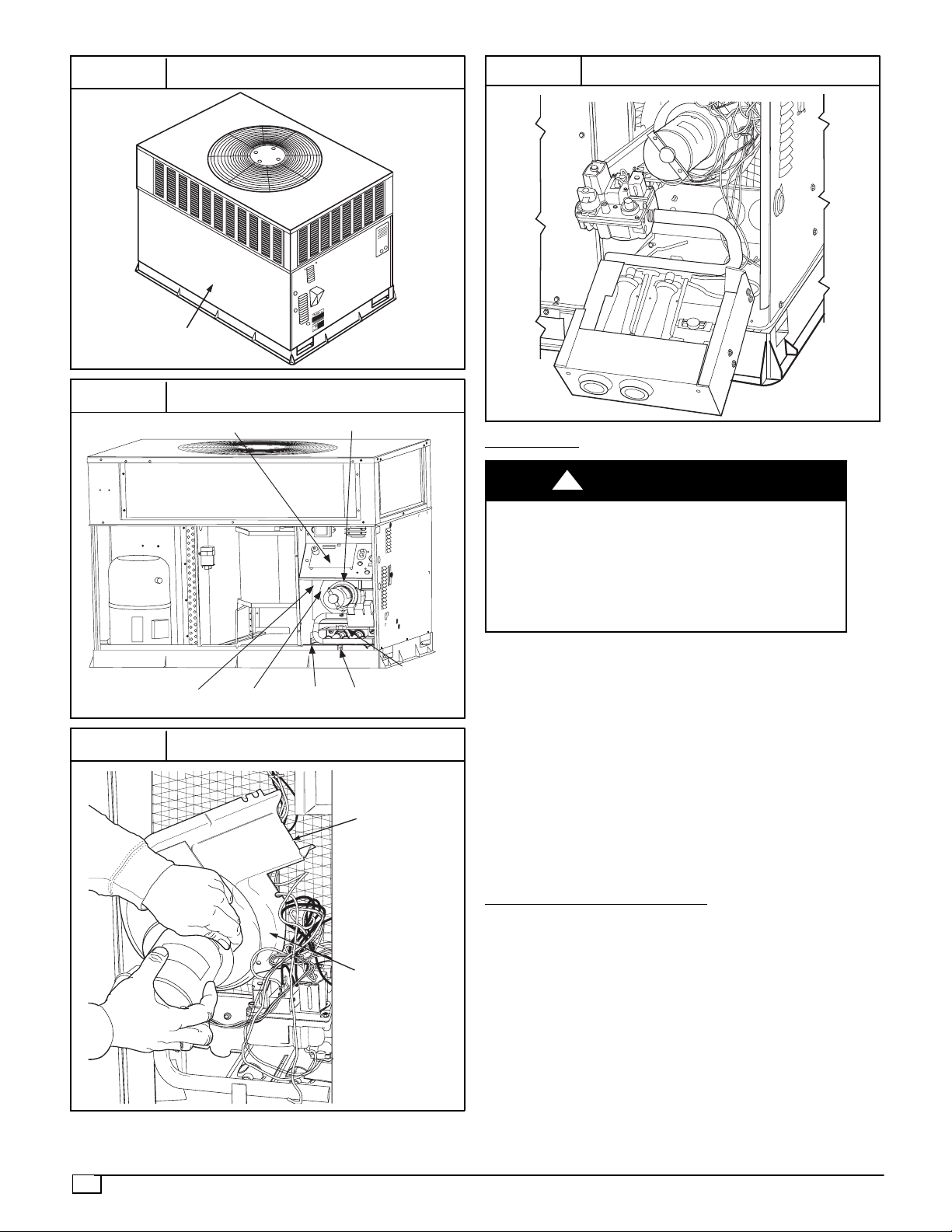
FIGURE 17
Unit Access Panel
FRONT
ACCESS PANEL
FIGURE 18
Blower Housing and Flue Collector Box
INDUCED DRAFT MOTOR MOUNT
FLUE
COLLECTOR
BOX
BLOWER
HOUSING
BURNER
RACK
MOUNTING
SCREW
ROLLOU
T
SWITCH
IGNITION MODULE
FIGURE 19
Removal of Motor and Blower Wheel
BLOWER
HOUSING
2 SETSCREWS
(HIDDEN)
FIGURE 20
Burner Rack Removed
Outdoor Fan
UNIT OPERATION HAZARD
Failure to follow this caution may result in damage to
unit components.
Keep the condenser fan free from all obstructions to
ensure proper cooling operation. Never place articles
on top of the unit.
CAUTION
!
1. Remove 6 screws holding discharge grille and motor to
top cover.
2. Turn motor/grille assembly upside down on top cover to
expose fan blade.
3. Inspect the fan blades for cracks or bends.
4. If fan needs to be removed, loosen setscrew and slide
fan off motor shaft.
5. When replacing fan blade, position blade so that the
hub is 8” (3.2mm) away from the motor end (8”
(3.2mm) of motor shaft will be visible).
6. Ensure that setscrew engages the flat area on the
motor shaft when tightening.
7. Replace grille.
Electrical Controls and W
iring
Inspect and check the electrical controls and wiring
annually. Be sure to turn off the electrical power to the unit.
Remove access panel to locate all the electrical controls
and wiring. Check all electrical connections for tightness.
Tighten all screw connections. If any smoky or burned
connections are noticed, disassemble the connection,
clean all theparts, re--strip the wireend and reassemble the
connection properly and securely.
After inspecting the electrical controls and wiring, replace
all the panels. Start the unit, and observe at least one
complete cooling cycle to ensure proper operation. If
discrepancies are observed in operating cycle, or if a
suspected malfunction has occurred, check each electrical
25
component withthe proper electricalinstrumentation. Refer
to the unit wiring label when making these checks.
NOTE: Refer to the Cooling Sequence of Operation in this
document to understand proper control operation.
Refrigeration
Circuit
Annually inspect all refrigerant tubing connections and
the unit base for oil accumulations. Detecting oil generally
indicates a refrigerant leak.
EXPLOSION, SAFETY AND ENVIRONMENT AL
HAZARD
Failure to follow this warning could result in personal
injury, death or property damage.
System under pressure. Relieve pressure and recover all
refrigerant before system repair or final unit disposal. Use
all service ports and open all flow--control devices,
including solenoid valves.
!
WARNING
If oil is detected or if low cooling performance is
suspected, leak--test all refrigerant tubing using an
electronic leak--detector, halide torch, or liquid--soap
solution. If a refrigerant leak is detected, refer to the
Check for Refrigerant Leaks section.
If no refrigerant leaks are found and low cooling
performance is suspected, refer to the Checking and
Adjusting Refrigerant Charge section.
Gas
Input
The gas input does not require checking unless improper
heating performance is suspected. If a problem exists,
refer to the Start--Up section.
Evaporator Airflow
The heating and/or cooling airflow does not require
checking unless improper performance is suspected. If a
problem exists, be sure that all supply-- and return --air
grilles are open and free from obstructions, and that the
air filter is clean. When necessary, refer to the Indoor
Airflow and Airflow Adjustments section to check the
system airflow.
R--410A
Items
Metering Device (Thermostatic Expansion Valve
)
This metering device is a hard shutoff, balance port TXV.
The TXV maintains a constant superheat at the
evaporator exit resulting in higher overall system
efficiency.
Pressure Switches
Pressure switches are protective devices wired into
control circuit (low voltage). They shut off compressor if
abnormally high or low pressures are present in the
refrigeration circuit. These pressure switches are
specifically designed to operate with R--410A systems.
R--22 pressure switches must not be used as
replacements for the R--410A system.
Loss of Charge Switch
This switch is located on the liquid line and protects
against low suction pressures caused by such events as
loss of charge, low airflow across indoor coil, dirty filters,
etc. It opens on a pressure drop at about 20 psig. If
system pressure is above this, switch should be closed.
To check switch:
1. Turn off all power to unit.
2. Disconnect leads on switch.
3. Apply ohm meter leads across switch. You should have
continuity on a good switch.
NOTE:Because these switches are attached to
refrigeration system under pressure, it is not advisable to
remove this device for troubleshooting unless you are
reasonably certain that a problem exists. If switch must
be removed, remove and recover all system charge so
that pressure gauges read 0 psi. Never open system
without breaking vacuum with dry nitrogen.
High--Pressure
Switch
The high--pressure switch is located in the discharge line
and protects against excessive condenser coil pressure.
It opens at 650 psig.
High pressure may be caused by a dirty outdoor coil,
failed fan motor, or outdoor air recirculation. To check
switch:
1. Turn off all power to unit.
2. Disconnect leads on switch.
3. Apply ohm meter leads across switch. You should have
continuity on a good switch.
Copeland Scroll Compressor (R--410A
Refrigerant)
The compressor used in this product is specifically
designed to operate with R--410A refrigerant and cannot
be interchanged.
The compressor is an electrical (as well as mechanical)
device. Exercise extreme caution when working near
compressors. Power should be shut off, if possible, for
most troubleshooting techniques. Refrigerants present
additional safety hazards.
FIRE/EXPLOSION HAZARD
Failure to follow this warning could result in personal
injury or death and/or property damage.
Wear safety glasses and gloves when handling
refrigerants. Keep torches and other ignition sources
away from refrigerants and oils.
!
WARNING
The scroll compressor pumps refrigerant throughout the
system by the interaction of a stationary and an orbiting
scroll. The scroll compressor has no dynamic suction or
discharge valves, and it is more tolerant of stresses
caused by debris, liquid slugging, and flooded starts. The
compressor is equipped with an anti--rotational device
and an internal pressure relief port. The anti--rotational
device prevents the scroll from turning backwards and
replaces the need for a cycle protector. The pressure
relief port is a safety device, designed to protect against
extreme high pressure. The relief port has an operating
range between 550 psi (26.34 kPa) and 625 psi (29.93
kPa) differential p ressure.
 Loading...