


NH4A4
INSTALLATION INSTRUCTIONS
R−410A Horizontal Split System Air Conditioner
NH4A4
These instructions must be read and understood completely before attempting installation.
SAFETY CONSIDERATIONS
Improper installation, adjustment, alteration, service, maintenance,
or use can cause explosion, fire, electrical shock, or other
conditions which may cause death, personal injury, or property
damage. Consult a qualified installer, service agency, or your
distributor or branch for information or assistance. The qualified
installer or agency must use factory−authorized kits or accessories
when modifying this product. Refer to the individual instructions
packaged with the kits or accessories when installing.
Follow all safety codes. Wear safety glasses, protective clothing,
and work gloves. Use quenching cloth for brazing operations.
Have a fire extinguisher available. Read these instructions
thoroughly and follow all warnings or cautions included in
literature and attached to the unit. Consult local building codes and
the current editions of the National Electrical Code (NEC)
NFPA70.
In Canada, refer to the current editions of the Canadian Electrical
Code CSA C22.1.
TABLE OF CONTENTS
PAGE
SAFETY CONSIDERATIONS 1........................
INSTALLATION 2−3.................................
Complete Pre−Installation Checks 2...................
Rig and Mount Unit 2..............................
Complete Refrigerant Piping Connections 3.............
Make Electrical Connections 3........................
START−UP 4........................................
SERVICE 4.........................................
MAINTENANCE 6...................................
Recognize safety information. This is the safety−alert symbol
When you see this symbol on the unit and in instructions or
manuals, be alert to the potential for personal injury. Understand
the signal words DANGER, WARNING, and CAUTION. These
words are used with the safety−alert symbol. DANGER identifies
the most serious hazards which will result in severe personal injury
or death. WARNING signifies hazards which could result in
personal injury or death. CAUTION is used to identify unsafe
practices which may result in minor personal injury or product and
property damage. NOTE is used to highlight suggestions which
will result in enhanced installation, reliability, or operation.
!
ELECTRICAL SHOCK HAZARD
Failure to follow this warning could result in personal injury
or death.
Before installing, modifying, or servicing system, main
electrical disconnect switch must be in the OFF position.
There may be more than 1 disconnect switch. Lock out and
tag switch with a suitable warning label.
WARNING
.
!
ENVIRONMENTAL HAZARD
Failure to follow this caution may result in environmental
pollution.
Remove and recycle all components or materials (i.e. oil,
refrigerant, etc.) before unit final disposal.
CAUTION
421 01 9703 01 02/25/15
INSTALLATION
IMPORTANT: Effective January 1, 2015, all split system and
packaged air conditioners must be installed pursuant to applicable
regional efficiency standards issued by the Department of Energy.
!
CAUTION
CUT HAZARD
Failure to follow this caution may result in personal injury.
Sheet metal parts may have sharp edges or burrs. Use care and
wear appropriate protective clothing and gloves when
handling parts.
!
UNIT OPERATION AND SAFETY HAZARD
Failure to follow this warning could result in personal injury
or equipment damage.
R−410A refrigerant systems operate at higher pressures than
standard R−22 systems. Do not use R−22 service equipment
or components on R−410A refrigerant equipment.
PERSONAL INJURY AND EQUIPMENT DAMAGE
HAZARD
Failure to follow this caution may result in personal injury
and / or equipment damage.
DO NOT operate the unit without a filter or with grille
removed.
COMPLETE PRE−INSTALLATION CHECKS
Unpack Unit
Move the unit to final location. Remove unit from carton, being
careful not to damage service valves and grilles.
Inspect Shipment
File a claim with the shipping company if shipment is damaged or
incomplete. Check the unit nameplates to ensure units match job
requirements.
Consider System Requirements
Consult local building codes and NEC for special installation
requirements.
Allow sufficient space for airflow clearance, wiring, refrigerant
piping, and servicing unit. Locate unit so that condenser airflow is
unrestricted on both sides.
Unit may be mounted on a level pad directly on base legs or
mounted on raised pads at support points.
RIG AND MOUNT UNIT
Mounting on Ground
Mount unit on a solid, level concrete pad. Position unit so water or
ice from roof does not fall directly onto unit. Use field−provided
snow stand or ice rack where prolonged subfreezing temperatures
or heavy snow occurs.
If conditions or local codes require unit be fastened to a pad, 6
field−supplied tie−down bolts should be used and fastened through
slots provided in unit mounting feet.
Mounting on Roof
Mount unit on a level platform or frame at least 6 in. (152.4 mm)
above roof surface. Isolate unit and tubing from structure.
WARNING
!
CAUTION
Clearance Requirements
Single Unit Applications: With coil facing wall: Allow 6” (152.4
mm) minimum clearance on coil side and coil end and 20” (504.0
mm) minimum clearance on fan side. Allow 24” (609.6 mm)
minimum clearance on compressor end for service.
With fan facing wall:
fan side and coil end and 20” (504.0 mm) minimum clearance on
coil side. Allow 24” (609.6 mm) minimum clearance on
compressor end for service when units are stacked or there is less
than 40” (1016 mm) of clearance above the unit. If there is 40”
(1016 mm) clearance above unit and the top panel is accessible for
removal allow 8” (203.2 mm) minimum clearance on compressor
end for service.
Multi−unit Applications:
clearance between fan and coil sides of multiple units. Arrange
units so discharge of one does not enter inlet of another. Allow 24”
(609.6 mm) minimum clearance on compressor end when units are
stacked or there is less than 40” (1016 mm) of clearance above the
unit. If there is 40” (1016 mm) clearance above unit and the top
panel is accessible for removal allow 8” (203.2 mm) minimum
clearance on compressor end for service.
When two units are installed end to end with the coil ends facing
each other allow 12” (304.8 mm) minimum clearance between
units.
IMPORTANT: When installing multiple units, ensure the
discharge air from one unit is not drawn into another unit. When
installing single or multiple units in an alcove, roof well, or
partially enclosed area, ensure there is adequate ventilation to
prevent recirculation of discharge air.
Operating Ambient
Minimum outdoor operating ambient in cooling mode is 55_F
(13_C), maximum 125_F (52_C).
Rigging
PERSONAL INJURY AND/OR EQUIPMENT
DAMAGE HAZARD
Failure to follow this caution may result in personal injury
and/or equipment damage.
Be sure unit panels are securely in place prior to rigging.
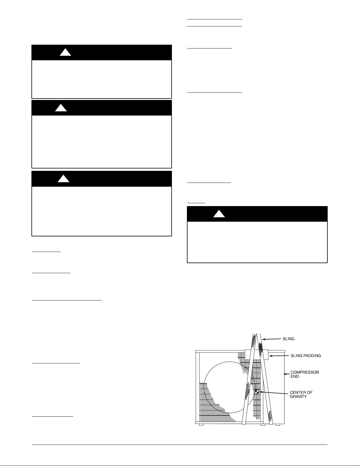
Keep the unit upright and lift unit using a sling. Use cardboard or
padding under the sling, and spreader bars to prevent sling damage
to the unit. See Fig. 1. Install the unit so that the coil does not face
into prevailing winds. If this is not possible and constant winds
above 25 mph are expected, use accessory wind baffle. See
installation instructions provided with the accessory kit.
NOTE: Accessory wind baffles should be used on all units with
accessory low ambient temperature control.
Field−fabricated snow or ice stands may be used to raise unit when
operation will be required during winter months. Units may also be
wall mounted using the accessory wall mounting kit.
Allow 8” (203.2 mm) minimum clearance on
Allow 24” (609.6 mm) minimum
!
CAUTION
Fig. 1 - Lifting Unit with Sling
A07396
2 421 01 9703 01
Specifications subject to change without notice.
 Loading...