


INSTALLATION INSTRUCTIONS
R−410A Variable Speed Split System Heat Pumps
CVH8, HVH8, TVH8
These instructions must be read and understood completely before attempting installation.
TABLE OF CONTENTS
PAGE NO.
SAFETY CONSIDERATIONS . . . . . . . . . . . . . . . . . . . . . . . . . . . . . . . 1 INSTALLATION RECOMMENDATIONS . . . . . . . . . . . . . . . . . . . . . 2 INSTALLATION . . . . . . . . . . . . . . . . . . . . . . . . . . . . . . . . . . . . . . . . . 2 STEP 1 — CHECK EQUIPMENT AND JOB SITE . . . . . . . . . . . . . . . 2 STEP 2 — INSTALL ON A SOLID, LEVEL MOUNTING PAD . . . . . 2 STEP 3 — CLEARANCE REQUIREMENTS . . . . . . . . . . . . . . . . . . . 3 STEP 4 — OPERATING AMBIENT . . . . . . . . . . . . . . . . . . . . . . . . . . 3 STEP 5 — ELEVATE UNIT . . . . . . . . . . . . . . . . . . . . . . . . . . . . . . . . . 3 STEP 6 — MAKE PIPING CONNECTIONS . . . . . . . . . . . . . . . . . . . . 3
REFRIGERANT CONNECTIONS AND RECOMMENDED
LIQUID AND VAPOR TUBE DIAMETERS (IN.) . . . . . . . . . . . . . . . 4 STEP 7 — MAKE ELECTRICAL CONNECTIONS . . . . . . . . . . . . . . 5 STEP 8 — COMPRESSOR CRANKCASE HEATER . . . . . . . . . . . . . 6
AIRFLOW SETUP FOR OBSERVER WALL CONTROL
FURNACE OR FAN COIL (COMMUNICATING) . . . . . . . . . . . . . . . 6 AIRFLOW SETUP FOR NON−COMMUNICATING FAN COIL . . . . 6 AIRFLOW SETUP FOR NON−COMMUNICATING FURNACES . . . 6 STEP 9 — INSTALL ACCESSORIES . . . . . . . . . . . . . . . . . . . . . . . . . 6 STEP 10 — START−UP . . . . . . . . . . . . . . . . . . . . . . . . . . . . . . . . . . . . 7
STEP 11 — SYSTEM FUNCTIONS AND
SEQUENCE OF OPERATION . . . . . . . . . . . . . . . . . . . . . . . . . . . . . . 7 STEP 12 — CHECK CHARGE . . . . . . . . . . . . . . . . . . . . . . . . . . . . . . 8 REQUIRED CHARGE ADJUSTMENT FOR INDOOR COIL MODEL 10 STEP 13 — PUMPDOWN & EVACUATION . . . . . . . . . . . . . . . . . . . 10 MAJOR COMPONENTS . . . . . . . . . . . . . . . . . . . . . . . . . . . . . . . . . . . 11 TROUBLESHOOTING . . . . . . . . . . . . . . . . . . . . . . . . . . . . . . . . . . . . 12 FACTORY SUPPLIED MODEL PLUG INFORMATION . . . . . . . . . . 12 10K/50KOHMS RESISTANCE VALUES VS TEMPERATURE . . . . . 12 VARIABLE SPEED COMPRESSOR RESISTANCE . . . . . . . . . . . . . . 14 TROUBLESHOOTING . . . . . . . . . . . . . . . . . . . . . . . . . . . . . . . . . . . . 15 FINAL CHECKS . . . . . . . . . . . . . . . . . . . . . . . . . . . . . . . . . . . . . . . . . 15 CARE AND MAINTENANCE . . . . . . . . . . . . . . . . . . . . . . . . . . . . . . 15 TECHNICAL LABELS . . . . . . . . . . . . . . . . . . . . . . . . . . . . . . . . . . . . 16 R−410A QUICK REFERENCE GUIDE . . . . . . . . . . . . . . . . . . . . . . . . 23
IMPORTANT: Effective January 1, 2015, all split system and packaged air conditioners must be installed pursuant to applicable regional efficiency standards issued by the Department of Energy.
Information in these installation instructions pertains only to CVH8, HVH8, TVH8 series units.
SAFETY CONSIDERATIONS
Improper installation, adjustment, alteration, service, maintenance, or use can cause explosion, fire, electrical shock, or other conditions which may cause death, personal injury, or property damage. Consult a qualified installer, service agency, or your
distributor or branch for information or assistance. The qualified installer or agency must use factory−authorized kits or accessories when modifying this product. Refer to the individual instructions packaged with the kits or accessories when installing.
Follow all safety codes. Wear safety glasses, protective clothing, and work gloves. Use quenching cloth for brazing operations. Have fire extinguisher available. Read these instructions thoroughly and follow all warnings or cautions included in literature and attached to the unit. Consult local building codes and current editions of the National Electrical Code (NEC) NFPA 70. In Canada, refer to current editions of the Canadian electrical code CSA 22.1.
Recognize safety information. This is the safety−alert symbol !! When you see this symbol on the unit and in instructions or manuals, be alert to the potential for personal injury. Understand these signal words; DANGER, WARNING, and CAUTION. These words are used with the safety−alert symbol. DANGER identifies the most serious hazards which will result in severe personal injury or death. WARNING signifies hazards which could result in personal injury or death. CAUTION is used to identify unsafe practices which would result in minor personal injury or product and property damage. NOTE is used to highlight suggestions which will result in enhanced installation, reliability, or operation.
!CAUTION
CUT HAZARD
Failure to follow this caution may result in personal injury.
Sheet metal parts may have sharp edges or burrs. Use care and wear appropriate protective clothing and gloves when handling parts.
!WARNING
UNIT OPERATION AND SAFETY HAZARD
Failure to follow this warning could result in personal injury or equipment damage.
R−410A refrigerant systems operate at higher pressures than standard R−22 systems. Do not use R−22 service equipment or components on R−410A refrigerant equipment.
!WARNING
ELECTRICAL SHOCK HAZARD
Failure to follow this warning could result in personal injury or death.
Before installing, modifying, or servicing system, main electrical disconnect switch must be in the OFF position. There may be more than 1 disconnect switch. Lock out and tag switch with a suitable warning label.
Specifications subject to change without notice. |
428 01 5700 00 10/19/15 |
Indoor Thermostat Control Options
Model |
Observer® Wall |
Standard |
|
Control |
HP Thermostat |
||
|
|||
CVH8, HVH8, |
Yes* |
Yes** |
|
TVH8 |
|||
|
|
NOTE: TSTAT0201CW Communicating Wi-Fi wall control. Non Wi-Fi cannot be used.
All trademarks are the property of their respective owners. Wi-Fi® is a regis tered trademark of Wi-Fi Alliance Corporation.
* Version 5.0 software or newer required.
** Using standard HP thermostat limits functionality of system.
!WARNING
ELECTRICAL HAZARD − HIGH VOLTAGE!
Failure to follow this warning could result in personal injury or death.
Electrical components may hold charge. DO NOT remove control box cover for 2 minutes after power has been removed from unit.
PRIOR TO TOUCHING ELECTRICAL COMPONENTS:
Verify zero (0) voltage at inverter connections shown on inverter cover.
!WARNING
EXPLOSION HAZARD
Failure to follow this warning could result in death, serious personal injury, and/or property damage.
Never use air or gases containing oxygen for leak testing or operating refrigerant compressors. Pressurized mixtures of air or gases containing oxygen can lead to an explosion.
Inverter Cover
IMPORTANT: The inverter cover should NEVER be removed because there is no reason to remove the inverter cover to access the inverter. The inverter has limited serviceability. Refer to Service Manual for details on field replaceable parts. A replacement cover is provided with a replacement inverter.
INSTALLATION RECOMMENDATIONS
In some cases noise in the living area has been traced to gas pulsations from improper installation of equipment.
1.Locate unit away from windows, patios, decks, etc. where unit operation sound may disturb customer.
2.In noise sensitive applications (such as bedrooms), when a lineset is mounted to ceiling joists or floor joists, the outdoor unit must be located at least 10 ft (3.05 m) away. If this is not possible, create a line set configuration with enough bends to provide 10 ft (3.05 m) of total line set length outside the dwelling
3.Ensure that vapor and liquid tube diameters are appropriate for unit capacity.
4.Run refrigerant tubes as directly as possible by avoiding unnecessary turns and bends.
5.Leave some slack between structure and unit to absorb vibration.
6.When passing refrigerant tubes through the wall, seal opening with RTV or other pliable silicon−based caulk (see Fig. 1).
7.Avoid direct tubing contact with water pipes, duct work, floor joists, wall studs, floors, and walls.
8.Do not suspend refrigerant tubing from joists and studs with a rigid wire or strap which comes in direct contact with tubing (see Fig. 1).
9.Ensure that tubing insulation is pliable and completely surrounds vapor tube.
10.When necessary, use hanger straps which are 1 in. wide and conform to shape of tubing insulation. (See Fig. 1.)
11.Isolate hanger straps from insulation by using metal sleeves bent to conform to shape of insulation.
12.If these installation recommendations were not followed, gas pulsation may be transmitted through improperly mounted line sets. In this case, an external vapor line muffler accessory (part no. 1187979) is available to minimize noise due to gas pulsations.
!CAUTION
EQUIPMENT DAMAGE HAZARD
Failure to follow this caution may result in equipment damage.
If proper lineset routing techniques are not followed, variable speed systems can be susceptible to lineset transmitted noise inside the dwelling and, in extreme cases, tubing breakage.
OUTDOOR WALL |
|
INDOOR WALL |
CAULK
LIQUID TUBE
|
SUCTION TUBE |
|
INSULATION |
|
|
THROUGH THE WALL |
|
|
|
JOIST |
|
HANGER STRAP |
|
|
(AROUND SUCTION |
INSULATION |
|
TUBE ONLY) |
||
|
||
|
SUCTION TUBE |
1” (25.4 mm) |
|
|
|
|
|
|
|
|
|
|
|
|
MIN |
|
|
|
|
|
|
|
|
|
|
LIQUID TUBE |
|
|
|
|
|
|
|
|
|
|
|
|||
|
|
SUSPENSION |
||||||||||
A07588
Fig. 1 − Connecting Tubing Installation
The outdoor unit contains the correct amount of refrigerant charge for operation with AHRI rated indoor units when connected by 15 ft (4.57 m) of field−supplied or factory accessory tubing.
See Step 12. on page 8 for proper charging procedure. IMPORTANT: Liquid−line size is 3/8−in. OD for all CVH8, HVH8, TVH8 applications. The maximum allowable equivalent line set length is 100 ft. (30.5 m).
IMPORTANT: Always install the factory−supplied liquid−line filter drier. Obtain replacement filter driers from your distributor or branch.
INSTALLATION
Specifications for this unit in residential new construction market require the outdoor unit, indoor unit (including metering device), refrigerant tubing sets, and filter drier listed in pre−sale literature. There can be no deviation. Consult the Service Manual – Air Conditioners and Heat Pumps Using R−410A Refrigerant to obtain required unit changes for specific applications and for R−22 retrofit.
Step 1 — Check Equipment and Job Site
Unpack Unit
Move to final location. Remove carton taking care not to damage unit.
2 |
Specifications subject to change without notice. |
428 01 5700 00 |
|
Inspect Equipment
File claim with shipping company prior to installation if shipment is damaged or incomplete. Locate unit rating plate on unit corner panel. It contains information needed to properly install unit. Check rating plate to be sure unit matches job specifications.
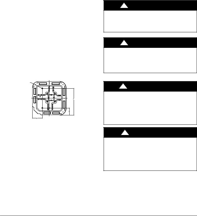
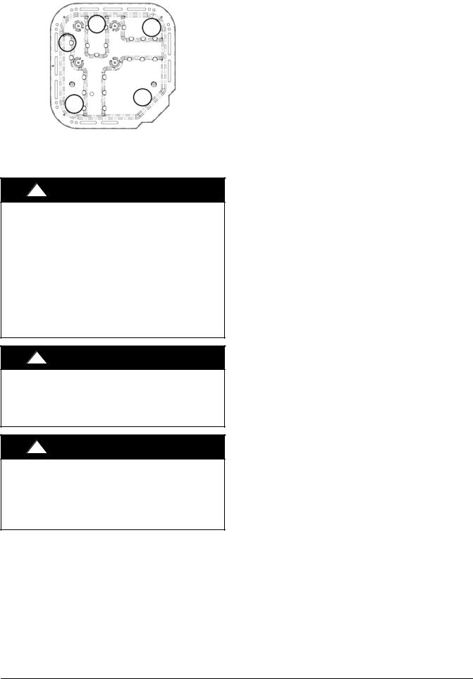
Step 2 — Install on a Solid, Level Mounting Pad
If conditions or local codes require the unit be attached to pad, tie down bolts should be used and fastened through knockouts provided in unit base pan. Refer to unit mounting pattern in Fig. 2 to determine base pan size and knockout hole location.
For hurricane tie downs, contact distributor for details and PE (Professional Engineer) Certification, if required.
On rooftop applications, mount on level platform or frame. Place unit above a load−bearing wall and isolate unit and tubing set from structure. Arrange supporting members to adequately support unit and minimize transmission of vibration to building. Consult local codes governing rooftop applications.
Roof mounted units exposed to winds above 5 mph may require wind baffles. Consult the Service Manual − Residential Split System Air Conditioners and Heat Pumps Using R−410A Refrigerant for wind baffle construction.
NOTE: Unit must be level to within ±2° (±3/8 in./ft,±9.5 mm/m.) per compressor manufacturer specifications.
Step 3 — Clearance Requirements
When installing, allow sufficient space for airflow clearance, wiring, refrigerant piping, and service. Allow 24 in. (609.6 mm) clearance to service end of unit and 48 in. (1219.2 mm) (above unit. For proper airflow, a 6−in. (152.4 mm) clearance on 1 side of unit and 12−in. (304.8 mm) on all remaining sides must be maintained. Maintain a distance of 24 in. (609.6 mm) between units. Position so water, snow, or ice from roof or eaves cannot fall directly on unit.
On rooftop applications, locate unit at least 6 in. (152.4 mm) above roof surface.
3/8-in. (9.53 mm) Dia. Tie-down Knockouts in Basepan(2) Places
View From Top
A05177
UNIT BASE PAN |
TIEDOWN KNOCKOUT LOCATIONS in. (mm) |
||||
Dimension in. (mm) |
A |
B |
C |
||
|
|
||||
23 X 23 |
7-13/16 (198) |
4-7/16 (102) |
18-1/8 (458) |
||
(596 |
X 596) |
||||
|
|
|
|||
31.2 |
X 31.2 |
9-1/8 (232) |
6-9/16 (167) |
24-11/16 (627) |
|
(792 |
X 792) |
||||
|
|
|
|||
Fig. 2 − Tie−down Knockout Locations
Step 4 — Operating Ambient
The minimum outdoor operating ambient in cooling mode is 40_F (4.4_C) with Observer®Wall Control, 55_F (12.8_C) with non−communicating systems. The maximum outdoor operating ambient in cooling mode is 115_F (46.1_C). Compressor protections will prevent cooling mode operation below minimum ambient temperature range. The system may operate in cooling up to 125_F (52_C) (52C) with significant reduced capacity cutback above 115_F (46.1_C). Refer to Product Data “Detailed Cooling Capacity” table. Low ambient cooling operation is not currently available. The maximum heating operation ambient is 66_F (18.9_C). Compressor protections will prevent starting below 10_F (−12.2_C) and operation below 2_F (−16.7_C).
Step 5 — Elevate Unit
Elevate unit per local climate and code requirements to provide clearance above estimated snowfall level and ensure adequate drainage of unit.
!CAUTION
UNIT OPERATION HAZARD
Failure to follow this caution may result in equipment damage or improper operation.
Do not allow water and/or ice to build up in base pan.
!CAUTION
UNIT OPERATION HAZARD
Failure to follow this caution may result in equipment damage or improper operation.
Locate the unit in such a way that it is stable in all circumstances including adverse weather conditions.
Step 6 — Make Piping Connections
!WARNING
PERSONAL INJURY AND UNIT DAMAGE HAZARD
Failure to follow this warning could result in personal injury or death.
Relieve pressure and recover all refrigerant before system repair or final unit disposal. Use all service ports and open all flow−control devices, including solenoid valves.
!CAUTION
UNIT DAMAGE HAZARD
Failure to follow this caution may result in equipment damage or improper operation.
Do not leave system open to atmosphere any longer than minimum required for installation. POE oil in compressor is extremely susceptible to moisture absorption. Always keep ends of tubing sealed during installation.
428 01 5700 00 |
Specifications subject to change without notice. |
3 |
|
!CAUTION
UNIT DAMAGE HAZARD
Failure to follow this caution may result in equipment damage or improper operation.
If ANY refrigerant tubing is buried, provide a 6 in. (152.4 mm) vertical rise at service valve. Refrigerant tubing lengths up to 36 in. (914.4 mm) may be buried without further special consideration. Do not bury lines longer than 36 in. (914.4 mm).
Outdoor units may be connected to indoor section using accessory tubing package or field−supplied refrigerant grade tubing of correct size and condition. For tubing requirements between 80 − 100 ft. (24.38 − 30.48 m), capacity and performance losses can occur. Follow the pipe sizing recommendations in the CVH8, HVH8, TVH8 Product data to manage these losses. This unit shall not be installed with greater than 100 ft (30.48 m) of equivalent line length.
Refer to Table 1 for field tubing diameters. No additional accessories are required for line lengths between 80 − 100 ft. (24.4 − 30.5 m) on this product.
Table 1 – Refrigerant Connections and Recommended Liquid and Vapor Tube Diameters (in.)
|
|
LIQUID |
|
VAPOR† |
|
UNIT SIZE |
Connection |
Tube |
Connection |
Max (Rated) |
Minimum |
|
Diameter |
Diameter |
Diameter |
Diameter |
Tube Diameter |
24 |
3/8 |
3/8 |
3/4 |
3/4 |
5/8 |
25 |
3/8 |
3/8 |
3/4 |
7/8 |
5/8 |
36, 37 |
3/8 |
3/8 |
3/4 |
7/8 |
5/8 |
48 |
3/8 |
3/8 |
7/8 |
(1-1/8) |
3/4 |
60 |
3/8 |
3/8 |
7/8 |
(1-1/8) |
3/4 |
{ Units are rated with 25 ft. (7.6 m) of lineset. See Product Data sheet for performance data when using different size and length line sets.
Notes:
1. Do not apply capillary tube indoor coils to these units.
Outdoor Unit Connected to Factory−Approved Indoor Unit
Outdoor unit contains correct system refrigerant charge for operation with factory−approved, AHRI−rated indoor units when connected by 15 ft. (4.57 m) of field−supplied or factory−accessory tubing, and factory−supplied filter drier. Check refrigerant charge for maximum efficiency.
NOTE: If the indoor furnace coil width is more than the furnace casing width, refer to the indoor coil Installation Instructions for transition requirements.
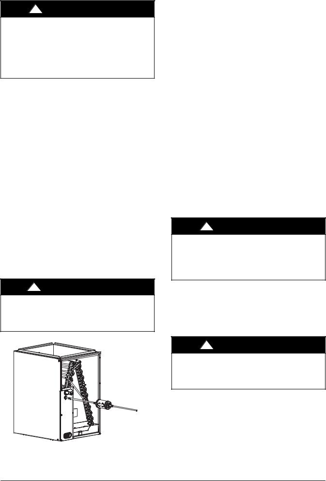
Install Liquid−Line Filter Drier Indoor
Refer to Fig. 3 and install filter drier as follows:
1.Braze 5−in. (127 mm) liquid tube to the indoor coil.
2.Wrap filter drier with damp cloth.
3.Braze filter drier to above 5−in. (127 mm) liquid tube.
4.Connect and braze liquid refrigerant tube to the filter drier.
!CAUTION
UNIT DAMAGE HAZARD
Failure to follow this caution may result in unit damage or improper operation.
Installation of filter drier in liquid line is required.
Refrigerant Tubing connection Outdoor
Connect vapor tube to fitting on outdoor unit vapor service valves (see Table 1).
No Installation of Adapter Tube
Although it is a heat pump this unit has a standard AC liquid service valve. An electronic expansion valve (EXV) inside the unit serves as the heating expansion device.
Sweat Connections
!CAUTION
UNIT DAMAGE HAZARD
Failure to follow this caution may result in equipment damage or improper operation.
SUse a brazing shield
SWrap service valves with wet cloth or heat sink material.
Use refrigerant grade tubing. Service valves are closed from factory and ready for brazing. After wrapping service valve with a wet cloth, braze sweat connections using industry accepted methods and materials. Consult local code requirements. Refrigerant tubing and indoor coil are now ready for leak testing. This check should include all field and factory joints.
Evacuate Refrigerant Tubing and Indoor Coil
|
! |
CAUTION |
|
UNIT DAMAGE HAZARD |
|
|
Failure to follow this caution may result in equipment |
|
|
damage or improper operation. |
|
|
Never use the system compressor as a vacuum pump. |
|
|
Refrigerant tubes and indoor coil should be evacuated using the |
|
|
recommended deep vacuum method of 500 microns. The alternate |
|
|
triple evacuation method may be used. See Service Manual for |
|
|
triple evacuation method. Always break a vacuum with dry |
|
|
nitrogen prior to opening the refrigerant system for servicing. |
|
|
Deep Vacuum Method |
|
|
The deep vacuum method requires a vacuum pump capable of |
|
A05227 |
pulling a vacuum of 500 microns and a vacuum gauge capable of |
|
Fig. 3 − Liquid−Line Filter Drier |
accurately measuring this vacuum depth. The deep vacuum method |
|
is the most positive way of assuring a system is free of air and liquid water. (See Fig. 4)
4 |
Specifications subject to change without notice. |
428 01 5700 00 |
|

5000 |
|
|
|
|
|
|
|
4500 |
|
|
|
|
|
|
|
4000 |
|
|
|
|
|
LEAK IN |
|
3500 |
|
|
|
|
|
||
|
|
|
|
|
SYSTEM |
||
3000 |
|
|
|
|
|
||
|
|
|
|
|
|
|
|
2500 |
|
|
|
|
|
|
|
MICRONS2000 |
|
|
|
|
|
VACUUM TIGHT |
|
1500 |
|
|
|
|
|
||
|
|
|
|
|
TOO WET |
||
1000 |
|
|
|
|
|
||
|
|
|
|
|
TIGHT |
||
500 |
|
|
|
|
|
||
|
|
|
|
|
DRY SYSTEM |
||
|
|
|
|
|
|
||
0 |
1 |
2 |
3 |
4 |
5 |
6 |
7 |
|
|
|
MINUTES |
|
|
|
|
|
|
|
|
|
|
|
A95424 |
|
Fig. 4 − Deep Vacuum Graph |
|
|||||
Final Tubing Check
IMPORTANT: Check to be certain factory tubing on both indoor and outdoor unit has not shifted during shipment. Ensure tubes are not rubbing against each other or any sheet metal. Pay close attention to feeder tubes, making sure wire ties on feeder tubes are secure and tight.
Step 7 — Make Electrical Connections
!WARNING
ELECTRICAL SHOCK HAZARD
Failure to follow this warning could result in personal injury or death.
Do not supply power to unit with compressor terminal box cover removed.
Be sure field wiring complies with local and national fire, safety, and electrical codes, and voltage to system is within limits shown on unit rating plate. Contact local power company for correction of improper voltage. See unit rating plate for recommended circuit protection device.
NOTE: Operation of unit on improper line voltage constitutes abuse and could affect unit reliability. See unit rating plate. Do not install unit in system where voltage may fluctuate above or below permissible limits.
NOTE: Use copper wire only between disconnect switch and unit.
NOTE: Install branch circuit disconnect of adequate size per NEC to handle unit starting current. Locate disconnect within sight from and readily accessible from unit, per Section 440−14 of NEC.
Route Ground and Power Wires
Remove access panel to gain access to unit wiring. Extend wires from disconnect through power wiring hole provided and into unit control box.
!WARNING
ELECTRICAL SHOCK HAZARD
Failure to follow this warning could result in personal injury or death.
The unit cabinet must have an uninterrupted or unbroken ground to minimize personal injury if an electrical fault should occur. The ground may consist of electrical wire or metal conduit when installed in accordance with existing electrical codes.
Connect Ground and Power Wires
Connect ground wire to ground connection in control box for safety. Connect power wiring to contactor as shown in Fig. 5.
DISCONNECT
PER N. E. C. AND/OR LOCAL CODES
FIELD POWER
WIRING
FIELD GROUND
WIRING
TERMINAL
BLOCK
GROUND
LUG
A14028
Fig. 5 − Line Power Connections
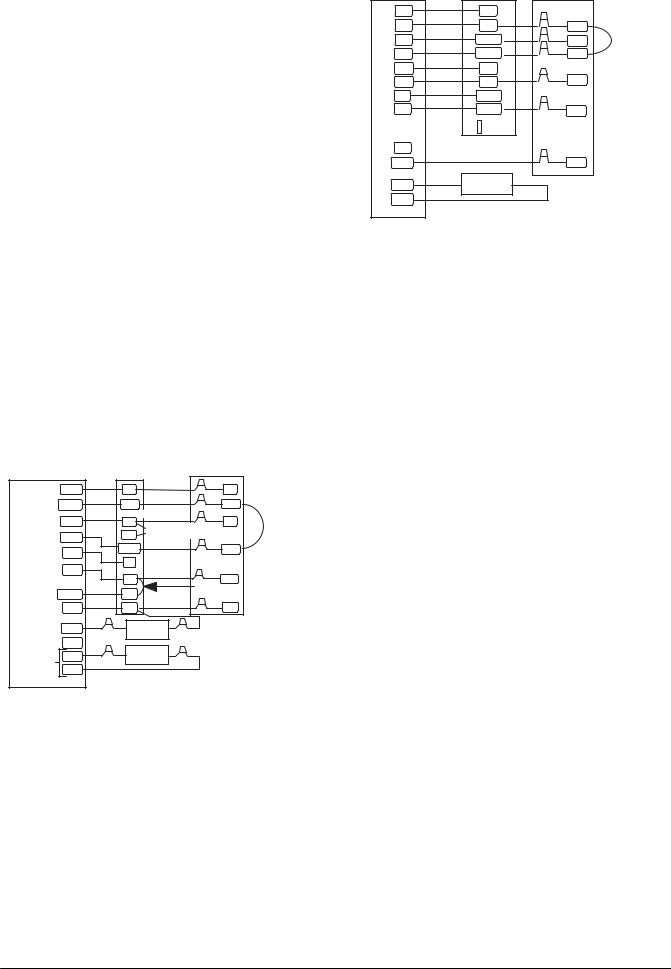
Connect Control Wiring−Observer® Wall
Connect four wires from Observer to communicating furnace / fan coil with communicating motor capability. Only two wires from furnace / fan coil DX+ (GR), DX− (YL) are connected to the outside inverter wiring GR (DX+), YL (DX−) (see Fig. 6). Connect C (WT) is recommended if wires are available (see Fig. 6). This will reduce the chance of communication issues. Unused low voltage wires should be bundled together and terminated with a wire nut at each end. The end nearest indoor coil should be connected to C terminal.
IMPORTANT: This system requires the power supplied to the outdoor unit, and the indoor unit, for the wall control to communicate with the outdoor unit.
Wall Control |
Furnace or Fan Coil |
|
Outdoor Unit |
|||||||||||
|
|
|
|
|
|
|
|
|
|
|
’R’ not required |
|
|
|
|
|
|
|
|
|
|
|
|
|
|
|
|
|
|
|
|
R |
|
|
|
R |
|
|
|
|
|
RD |
|
|
|
|
C |
|
|
|
C |
|
|
|
|
|
WT |
|
|
|
|
|
|
|
|
|
|
|
|
|
|
|
|
|
|
|
DXï |
|
|
|
DXï |
|
|
|
|
YL |
|
||
|
|
|
|
|
|
|
|
|
|
|
|
|
|
|
|
|
DX+ |
|
|
|
DX+ |
|
|
|
|
GR |
|
||
|
|
|
|
|
|
|
|
|
|
|
Shielded cable |
|
|
|
|
|
|
|
|
|
|
|
|
|
|
|
|
|
|
|
|
|
|
|
|
|
|
|
|
|
|
|
|
|
|
|
|
|
|
|
OAT |
|
|
|
|
’C’ connection optional |
|||
|
|
|
|
|
|
|
|
|
|
|||||
|
|
|
|
|
|
|
|
|
|
|
|
|
||
|
|
|
|
|
|
|
|
|
|
|
|
|||
|
|
|
|
|
|
|
|
|
|
|
|
|
|
|
|
|
|
|
|
|
|
|
|
|
|
|
|
||
|
|
|
|
|
|
|
R |
|
|
|
|
|
|
|
|
|
|
|
|
|
|
|
|
|
|
|
|
|
|
|
|
|
|
|
|
|
Y |
|
|
|
|
|
|
|
|
|
|
|
|
|
|
|
|
|
|
|
|
|
|
|
Humidifier |
|
|
O |
|
|
|
|
|
|
||||
|
|
|
|
|
|
|
|
|
|
|
||||
|
|
|
|
|
|
|
W |
|
|
|
|
|
|
|
|
|
C |
|
|
|
|
C |
|
|
|
|
|
|
|
|
|
|
|
|
|
|
|
|
|
|
|
|
|
|
|
|
24vac |
|
|
|
|
HUM |
|
|
|
|
|
|
|
|
|
|
|
|
|
|
|
|
|
|
|
|
|
|
A150636
Fig. 6 − Communicating Furnace or Fan Coil Wiring with Communicating Variable Speed HP
Connect Control Wiring− Non−Communicating
Six wires are required when connecting CVH8, HVH8, TVH8 models to non−communicating 2−stage thermostats. Use Fig. 7 For required connections. Unit is configured by factory for Observer communicating control. To wire unit for non−communicating control, disconnect the DX+ = GN and DX− = YL wires from green plug and connect appropriate wires to low voltage terminal block. Use wire nuts to attach thermostat wire to low voltage choke harness (LVCH).
428 01 5700 00 |
Specifications subject to change without notice. |
5 |
|
General Information
Use 18−20 solid AWG color−coded, insulated (355C minimum) wire for low voltage control wires. All wiring must be NEC Class 2 and must be separated from incoming power leads.
Installations using greater than 200 feet of low voltage wiring should consult the Evolution wall control manual for additional guidelines regarding daisy chaining wiring method and terminating resistors.
Never route control wiring in parallel to high voltage power wires when possible as electrical noise may transfer and generate nuisance fault codes. Where low voltage control and high voltage wires must cross paths, do so at perpendicular angles to eliminate transferred noise. If further communication issues exist, consider using shielded low voltage wires and only connect shielding to C terminal at end nearest indoor coil.
Use furnace transformer, fan coil transformer, or accessory transformer for control power requirement of system accessories external to the OD unit. The outdoor unit has its own transformer power.
Use No. 18 AWG or larger color−coded, insulated (35°C minimum) wire for low voltage control wires.
All wiring must be NEC Class 2 and must be separated from incoming power leads.
Use furnace transformer, fan coil transformer, or accessory transformer for control power requirement of system accessories external to the OD unit. The outdoor unit has its own transformer power.
Final Wiring Check
IMPORTANT: Check factory wiring and field wire connections to ensure terminations are secured properly. Check wire routing to ensure wires are not in contact with tubing, sheet metal, etc. Ensure that high and low voltage is separated where possible, to minimize induced noise from VFD to communication wiring.
Indoor Control |
Fan Coil |
Heat Pump |
|
|||
|
|
|
||||
RVS Cooling |
O/W2 |
O |
|
|
O |
|
Heat/Cool |
Y1/W2 |
Y1 |
|
|
Y1 |
|
Stage 1 |
|
|
|
|||
Heat Stage 3 |
W/W1 |
W1 |
s Remove J2 Jumper |
W1 |
Jumper Wire |
|
Heat/Cool |
|
|
|
Requred for |
||
|
W2 |
sFor Heat Staging |
|
|||
Y/Y2 |
|
Single Stage |
||||
Stage 2 |
Y/Y2 |
|
|
|
||
Fan |
G |
|
|
Y2 |
|
|
|
|
|
|
|
||
24 VAC Hot |
|
G |
|
|
|
|
R |
|
|
|
R |
|
|
|
|
R |
|
|
|
|
Dehumidify |
DHUM |
DH |
|
J1 Jumper on Control Board |
||
|
|
|
|
|||
24 VAC Comm |
C |
C |
|
|
C |
|
Humidify |
HUM |
Humidifier |
|
|
|
|
(24 VAC) |
|
|
|
|||
|
|
|
|
|
||
RVS Heating B |
Outdoor |
|
|
S1 |
|
Outdoor |
Sensor |
|
|
|
|
|
S2 |
|
A150198
Indoor Control |
Variable Speed |
Heat Pump |
Furnace |
||
W2 |
W2 |
|
Y1 |
Y1 |
Y1 |
W1 |
W/W1 |
W1 |
Y2 |
Y/Y2 |
Y2 |
G |
G |
|
R |
R |
R |
|
||
H |
DHUM |
|
C |
COM |
C |
|
HUM |
|
L |
|
|
O/B |
|
O |
OD |
OUTDOOR |
|
SENSOR |
|
|
|
|
|
GND |
|
|
Jumper Wire
Requred for
Single Stage
A150199
Fig. 7 − Low Voltage Wiring (Non−Communicating)
Step 8 — Compressor Crankcase Heater
This compressor has an internal crankcase heater. Furnish power to the unit a minimum of 24 hr before starting the unit for the first time.
Upon initial start−up of unit, status code 68 will be generated and system will operate at stage 2 for 11 minutes. This operation is important to system reliability and cannot be bypassed. Each time high voltage is removed and reapplied this behavior will be repeated.
To furnish power to heater only, set thermostat to OFF and close electrical disconnect to outdoor unit.
Power is not required to the indoor unit or Wall Control for proper operation of heater. Crankcase heater will be intelligently energized as needed between operations, even when the Wall Control or thermostat and indoor unit is not installed, as long as there is power to the outdoor unit.
Airflow Setup for Observer® Wall Control Furnace or FCM4X Fan Coil (communicating)
This system can only be installed with communicating indoor and Observer Wall Control TSTAT0201CW with Version 5.0 or higher software or newer. When using an Observer Wall Control, airflow is automatically selected based on equipment size. The user has the option of selecting Comfort, Efficiency and Max airflow for Heating and/or Cooling modes. These should be selected based on balance between the homeowner’s comfort and energy consumption expectations. See Observer Wall Control Installation Instructions for additional available adjustments.
Due to using a communicating control with the fan coil or the furnace, dip switch adjustments are not necessary. The outdoor unit configuration and the indoor airflows are determined by communicating control setup.
Airflow Setup for Non−communicating Fan Coil
The system can be installed with a standard 2−stage heat pump thermostat and FVM4X fan coil without additional accessories. Select appropriate unit size on fan coil Easy select board.
Airflow Setup for Non−communicating Furnaces
For installations with non−communicating furnaces, set airflows to 350−400 cfm/nominal ton in high stage and 70−80 percent of high stage airflow in low stage.
Step 9 — Install Accessories
No refrigeration circuit accessories are required or are available for installation within the unit. External to the unit, the same accessories such as support feet, wind baffle etc., available on other units, can also be used on this line of product. For models utilizing 23 inch x 23 inch base pans, it is recommended to use 5 support feet in order to fully support unit. See Fig. 8. Refer to the
6 |
Specifications subject to change without notice. |
428 01 5700 00 |
|
individual Installation Instructions packaged with kits or accessories when installing.
A14008
Fig. 8 − Recommended Support Feet Location
(for 23” x 23” basepan)
Step 10 — Start−Up
!CAUTION
UNIT OPERATION AND SAFETY HAZARD
Failure to follow this caution may result in minor personal injury, equipment damage or improper operation.
Observe the following:
1.Do not overcharge system with refrigerant.
2.Do not operate unit in a vacuum or at negative pressure. 3.Do not disable low pressure transducer or system safety devices such as discharge thermistor or the high pressure
switch.
4.Dome temperatures may be hot.
5.Discharge thermistor is engaged tight on the discharge tube.
!CAUTION
PERSONAL INJURY HAZARD
Failure to follow this caution may result in personal injury.
Wear safety glasses, protective clothing, and gloves when handling refrigerant.
!CAUTION
ENVIRONMENTAL HAZARD
Failure to follow this caution may result in environmental damage.
Federal regulations require that you do not vent refrigerant to the atmosphere. Recover during system repair or final unit disposal.
Step 11 — System Functions and Sequence of Operation
The CVH8, HVH8, TVH8 models utilize either Observer® Wall Control or conventional HP thermostat. When using Wall Control controls, a call for cooling will energize the outdoor fan and compressor to run at lowest cooling demand. If this does not satisfy cooling demand, the system will ramp up in stages until it satisfies the demand. After coping with the higher demand, the unit returns to lower capacity operation until the demand is satisfied or until an increase in demand. When using a conventional thermostat, the thermostat controls the staging of outdoor unit.
When all demand is satisfied, the compressor will shut off. As the unit operates at lower capacity, system vapor (suction) pressure will
be higher than it is during a standard single−stage system operation or during a higher capacity operation.
The Observer Wall Control displays the operation mode and fault codes as specified in the troubleshooting section. See Table 6 for codes and definitions.
The conventional thermostat inputs are designed to work with most indoor units. See AHRI for approved combinations. Connections are Y/Y2, Y1, O, R, W, and C. Depending on thermostat and indoor unit, the system will operate at 1 or 2 capacities in heating or cooling mode.
NOTE: Only one code will be displayed on the outdoor unit control board (the most recent, with the highest priority). The latest codes are stored and can be accessed via the Observer Wall Control.
Upon a call for cooling through the Observer Wall Control (or the Y1 and/or Y2 connections in a non−communicating system), the Application Operation Control (AOC) board (see Fig. 22) will open the EXV to the fully open position. For heating, the AOC board will open the EXV to a preset position, depending upon the conditions. Based upon the indoor space demand and the outdoor conditions, the Observer Wall Control will then request a compressor speed and outdoor fan motor speed.
If the conditions are correct for operation, the control board will allow the requested operation to begin, but if the control board determines that the conditions are not correct, the board will decide what other operation nearing that condition is acceptable. The inverter Motor Operational Control (MOC) then outputs the three−phase PWM signal and frequency that gently ramps the compressor speed up to stage 2, and then will adjust to the demanded speed. The gentle ramp−up results in no locked rotor amps to the compressor motor. The unit 0 for compressor LRA will be stamped N/A (not applicable).
During operation, the AOC monitors itself and the compressor operation along with the system pressures and temperatures. The MOC board monitors the temperature, current and operational status of the compressor, OD fan and the inverter itself. During operation, the compressor speed will be adjusted to meet the changes to the demand.
When the demand is satisfied, the inverter will ramp−down the compressor speed and stop. The EXV will step down to the completely closed position.
When the compressor stops, a 3.5 minute Time Guard period is activated which is followed by opening of the PEV valve for 150 seconds to equalize the refrigerant pressure difference between the high and low sides of the compressor. Upon equalizing the refrigerant pressure, and an additional 15 seconds of the Time Guard period, the compressor will be ready for the next operational demand.
If there is a power cycle, the Pressure Equalizer Valve (PEV) will open for 150 seconds before the compressor start−up. Opening the PEV valve returns the discharge gas directly back to the suction side of the compressor. This is done in either cooling or heating mode so that the rotary compressor will start with a very low pressure differential.
The 3.5 minute Time Guard can be bypassed by momentarily shorting the Forced Defrost pins. Only the 3.5 minute time delay can be bypassed. Because it is important for compressor reliability, the 150−second PEV delay cannot be bypassed.
Crankcase Heater Operation
This unit has an internal crankcase heater that will be energized during the off cycle and is intelligently demanded by the system to prevent the compressor from being the coldest part of the system thus enhancing the reliability. The crankcase heater will function as needed any time the outdoor unit is powered. The indoor unit and Observer Wall Control do not need to be installed for the crankcase heater to operate properly.
The compressor windings will occasionally be energized during the OFF cycle (depending on the length of the OFF cycle) to start the stator heat operation, thus maintaining a sump temperature that
428 01 5700 00 |
Specifications subject to change without notice. |
7 |
|
 Loading...