


International Comfort Products FEM4P1800A1, FSM4P1800A1, FSU4P1800A1, FEM4P1800AT1, FSM4P1800AT1 User Manual
...TECHNICAL SUPPORT MANUAL
Fan Coils
FEM4P, FSM4P, FSU4P
Safety Labeling and Signal Words
DANGER, WARNING, CAUTION, and NOTE
The signal words DANGER, WARNING, CAUTION, and NOTE are used to identify levels of hazard seriousness. The signal word DANGER is only used on product labels to signify an immediate hazard. The signal words WARNING, CAUTION, and NOTE will be used on product labels and throughout this manual and other manuals that may apply to the product.
DANGER − Immediate hazards which will result in severe personal injury or death.
WARNING − Hazards or unsafe practices which could result in severe personal injury or death.
CAUTION − Hazards or unsafe practices which may result in minor personal injury or product or property damage.
NOTE − Used to highlight suggestions which will result in enhanced installation, reliability, or operation.
Signal Words in Manuals
The signal word WARNING is used throughout this manual in the following manner:
!WARNING
The signal word CAUTION is used throughout this manual in the following manner:
!CAUTION
Signal Words on Product Labeling
Signal words are used in combination with colors and/or pictures on product labels.
TABLE OF CONTENTS
Model Number Identification . . . . . . . . . . . . . . . . . . . . . 2
FEM4P Wiring Diagram . . . . . . . . . . . . . . . . . . . . . . . . . 3
FSM4P, FSU4P Wiring Diagram . . . . . . . . . . . . . . . . . . 4
Airflow Tables . . . . . . . . . . . . . . . . . . . . . . . . . . . . . . . 5 − 7
Exploded Drawing . . . . . . . . . . . . . . . . . . . . . . . . . . 8 − 13
FEM4P*A1 Parts List . . . . . . . . . . . . . . . . . . . . . . 14 − 15
FEM4P*AT1 Parts List . . . . . . . . . . . . . . . . . . . . . 16 − 17
FSM4P*A1 Parts List . . . . . . . . . . . . . . . . . . . . . . 18 − 19
FSM4P*AT1 Parts List . . . . . . . . . . . . . . . . . . . . . 20 − 21
FSU4P*A1 Parts List . . . . . . . . . . . . . . . . . . . . . . 22 − 23
FSU4P*AT1 Parts List . . . . . . . . . . . . . . . . . . . . . 24 − 25
MODELS
FEM4P1800A1 |
FSM4P1800A1 |
FSU4P1800A1 |
FEM4P1800AT1 |
FSM4P1800AT1 |
FSU4P1800AT1 |
FEM4P2400A1 |
FSM4P2400A1 |
FSU4P2400A1 |
FEM4P2400AT1 |
FSM4P2400AT1 |
FSU4P2400AT1 |
FEM4P3000A1 |
FSM4P3000A1 |
FSU4P3000A1 |
FEM4P3000AT1 |
FSM4P3000AT1 |
FSU4P3000AT1 |
FEM4P3600A1 |
FSM4P3600A1 |
FSU4P3600A1 |
FEM4P3600AT1 |
FSM4P3600AT1 |
FSU4P3600AT1 |
FEM4P4200A1 |
FSM4P4200A1 |
FSU4P4200A1 |
FEM4P4200AT1 |
FSM4P4200AT1 |
FSU4P4200AT1 |
FEM4P4800A1 |
FSM4P4800A1 |
FSU4P4800A1 |
FEM4P4800AT1 |
FSM4P4800AT1 |
FSU4P4800AT1 |
!WARNING
ELECTRICAL SHOCK HAZARD
Failure to turn off electric power could result in personal injury or death.
Before installing or servicing system, turn off main power to the system. There may be more than one disconnect switch, including accessory heater(s).
496 04 5500 01 Sept. 2010

TECHNICAL SUPPORT MANUAL Fan Coils: FEM4P, FSM4P, FSU4P
|
FAN COIL MODEL NUMBER IDENTIFICATION GUIDE |
|
|
|
|||||||
|
|
F |
E |
M |
|
4 |
P |
|
1800 |
A |
T |
F = Fan Coil |
|
|
|
|
|
|
|
|
|
|
|
|
|
|
|
|
|
|
|
|
|
|
|
S = Standard PSC |
|
|
|
|
|
|
|
|
|
|
|
E = High efficiency ECM |
MOTOR TYPE |
|
|
|
|
|
|
|
|
||
|
|
|
|
|
|
|
|
|
|
|
|
U = Upflow |
|
|
|
|
|
|
|
|
|
|
|
M = Multiposition |
INSTALLATION TYPE |
|
|
|
|
|
|
||||
|
|
|
|
|
|
|
|
|
|
||
4 = Environmentally Sound R−410A |
|
|
REFRIGERANT |
|
|
|
|
|
|||
|
|
|
|
|
|
|
|
|
|
||
P = Piston Metering Device |
|
|
|
METERING DEVICE |
|
|
|
|
|||
|
|
|
|
|
|
|
|
|
|
|
|
1800 |
= 18,000 BTUH = 1½ tons |
|
|
|
|
|
|
|
|
|
|
2400 |
= 24,000 BTUH = 2 tons |
|
|
|
|
|
|
|
|
|
|
3000 |
= 30,000 BTUH = 2½ tons |
|
|
|
|
|
|
|
|
|
|
3600 |
= 36,000 BTUH = 3 tons |
|
|
|
|
|
|
|
|
|
|
4200 |
= 42,000 BTUH = 3½ tons |
|
|
|
|
|
|
|
|
|
|
4800 |
= 48,000 BTUH = 4 tons |
|
|
|
|
NOMINAL CAPACITY |
|
|
|||
|
|
|
|
|
|
|
|
||||
A = Standard |
|
|
|
|
|
|
|
|
|
|
|
AT = Tin coated copper tubes |
|
|
|
|
|
SALES CODE / FEATURES |
|||||
ACCESSORIES PART NUMBER IDENTIFICATION GUIDE |
|
|
|||
|
EB |
AC |
01 |
NCB |
A |
EB = Evaporator Blower |
|
|
|
|
|
|
|
|
|
|
|
AC = Accessory |
|
|
|
|
|
|
|
|
|
|
|
01 = Product Identifier Number |
|
|
|
|
|
|
|
|
|
|
|
NCB = Non−Combustible Base Kit |
|
|
|
|
|
DFK = Down Flow Kit |
|
|
|
|
|
PLG = Power Plug (no heat kit) |
|
|
|
|
|
SPK = Single Point Wiring Kit |
|
|
|
|
|
FKS = Filter Kit Small |
|
|
|
|
|
FKM = Filter Kit Medium |
|
|
|
|
|
FKL = Filter Kit Large |
|
|
|
|
|
FKX = Filter Kit Extra Large |
|
|
|
|
|
CTK = Condensate Trap Kit (PVC pipe) |
|
|
|
|
|
Sales Code |
|
|
|
|
|
|
|
ELECTRIC HEATER MODEL NUMBER IDENTIFICATION GUIDE |
|
|
||||
|
|
|
EHK |
05 |
A |
K |
N |
1 |
EHK = Electric Heater Kit |
|
|
|
|
|
|||
|
|
|
|
|
|
|
|
|
05 |
= 5 kW |
|
|
|
|
|
|
|
07 |
= 7 kW |
|
|
|
|
|
|
|
09 |
= 9 kW |
|
|
|
|
|
|
|
10 |
= 10 kW |
|
|
|
|
|
|
|
15 |
= 15 kW |
|
|
|
|
|
|
|
18 |
= 18 kW |
|
|
|
|
|
|
|
20 |
= 20 kW |
|
|
|
|
|
|
|
25 |
= 25 kW |
NOMINAL HEAT VALUE |
|
|
|
|
||
30 |
= 30 kW |
|
|
|
|
|||
Sales Code |
|
|
|
|
|
|
|
|
K = 208 / 230 single−phase H = 208 / 230, 3−phase
KC = 208 / 230, supplied as single phase, field convertible to 3−phase
HC = 208 / 230 supplied as 3−phase, field convertible to single phase VOLTAGE (60 Hz) Product Identifier
Engineering Code
2 |
496 04 5500 01 |

TECHNICAL SUPPORT MANUAL |
Fan Coils: FEM4P, FSM4P, FSU4P |
|
|
|
FEM4P |
496 04 5500 01 |
3 |

TECHNICAL SUPPORT MANUAL |
Fan Coils: FEM4P, FSM4P, FSU4P |
|
|
|
FSM4P & FSU4P |
|
NOTES |
|
1. Use Copper Wire (75ºC Min) Only |
|
Between Disconnect Switch And Unit. |
|
2. To Be Wired In Accordance With NEC |
|
And Local Codes. |
|
3. If Any Of The Original Wire, As |
|
Supplied, Must Be Replaced, Use The |
|
Same Or Equivalent Type Wire. |
|
4. Replace Low Voltage Fuse With No |
|
Greater Than 5 Amp Fuse. |
|
5. (3) Speed Motor Shown Optional (2) |
|
Speed Motor Uses HI (BLK) And LOW |
|
(BLUE or RED). |
|
6. Connect R To R, G To G, Etc. See |
|
Outdoor Instruction For Details. |
|
328964-101 REV. A |
4 |
496 04 5500 01 |

TECHNICAL SUPPORT MANUAL |
|
|
|
|
Fan Coils: FEM4P, FSM4P, FSU4P |
|
|||
|
|
|
|
|
|
||||
|
|
|
|
|
|
||||
|
AIRFLOW PERFORMANCE − CFM at a given Speed and Static reading |
|
|
|
|||||
Model |
Blower Speed |
|
|
Total Static (inches water column) |
|
|
|
||
0.10 |
0.20 |
0.30 |
0.40 |
0.50 |
0.60 |
|
|||
|
|
|
|||||||
|
Tap 5 |
|
|
|
|
669 |
620 |
565 |
|
|
767 |
739 |
702 |
|
|||||
|
Tap 4 |
614 |
569 |
534 |
486 |
436 |
398 |
|
|
FEM4P1800 |
Tap 3 |
701 |
660 |
616 |
581 |
537 |
499 |
|
|
|
Tap 2 |
614 |
569 |
534 |
486 |
436 |
398 |
|
|
|
Tap 1 |
614 |
569 |
534 |
486 |
436 |
398 |
|
|
|
Tap 5 |
969 |
936 |
|
892 |
835 |
763 |
676 |
|
|
Tap 4 |
826 |
795 |
|
766 |
743 |
706 |
660 |
|
FEM4P2400 |
Tap 3 |
826 |
795 |
766 |
743 |
706 |
660 |
|
|
|
Tap 2 |
701 |
660 |
616 |
581 |
537 |
499 |
|
|
|
Tap 1 |
617 |
592 |
552 |
507 |
472 |
420 |
|
|
|
Tap 5 |
1108 |
1090 |
1065 |
1034 |
1009 |
974 |
|
|
|
Tap 4 |
1026 |
1000 |
969 |
938 |
899 |
865 |
|
|
FEM4P3000 |
Tap 3 |
1026 |
1000 |
969 |
938 |
899 |
865 |
|
|
|
Tap 2 |
909 |
873 |
842 |
799 |
762 |
724 |
|
|
|
Tap 1 |
825 |
795 |
757 |
722 |
674 |
634 |
|
|
|
Tap 5 |
1301 |
1276 |
1245 |
1218 |
1176 |
1121 |
|
|
|
Tap 4 |
1227 |
1191 |
1169 |
1143 |
1105 |
1074 |
|
|
FEM4P3600 |
Tap 3 |
1227 |
1191 |
1169 |
1143 |
1105 |
1074 |
|
|
|
Tap 2 |
1087 |
1062 |
1030 |
1001 |
966 |
930 |
|
|
|
Tap 1 |
1026 |
1000 |
969 |
938 |
899 |
865 |
|
|
|
Tap 5 |
1560 |
1544 |
1507 |
1464 |
1424 |
1358 |
|
|
|
Tap 4 |
1419 |
1397 |
1358 |
1320 |
1279 |
1239 |
|
|
FEM4P4200 |
Tap 3 |
1419 |
1397 |
1358 |
1320 |
1279 |
1239 |
|
|
|
Tap 2 |
1249 |
1220 |
1184 |
1142 |
1093 |
1052 |
|
|
|
Tap 1 |
1242 |
1205 |
1158 |
1110 |
1069 |
1026 |
|
|
|
Tap 5 |
1743 |
1712 |
1679 |
1642 |
1610 |
1574 |
|
|
|
Tap 4 |
1669 |
1634 |
1599 |
1564 |
1531 |
1499 |
|
|
FEM4P4800 |
Tap 3 |
1669 |
1634 |
1599 |
1564 |
1531 |
1499 |
|
|
|
Tap 2 |
1452 |
1413 |
1377 |
1339 |
1308 |
1271 |
|
|
|
Tap 1 |
1300 |
1256 |
1221 |
1182 |
1142 |
1101 |
|
|
AIRFLOW PERFORMANCE − CFM at a given Speed and Static reading
|
Blower |
|
|
|
|
Total Static (inches water column) |
|
|
|
|
||||
Model |
0.10 |
0.20 |
0.30 |
0.40 |
0.50 |
0.60 |
||||||||
Speed |
||||||||||||||
|
208V |
230V |
208V |
230V |
208V |
230V |
208V |
230V |
208V |
230V |
208V |
230V |
||
|
|
|||||||||||||
|
|
|
|
|
|
|
|
|
|
|
|
|
|
|
FSM4P1800 |
High |
742 |
825 |
707 |
768 |
642 |
714 |
568 |
648 |
466 |
526 |
403 |
434 |
|
FSU4P1800 |
Low |
541 |
608 |
480 |
564 |
417 |
511 |
357 |
431 |
299 |
363 |
n/a |
304 |
|
FSM4P2400 |
High |
1041 |
1112 |
969 |
1030 |
888 |
936 |
774 |
791 |
573 |
654 |
341 |
438 |
|
FSU4P2400 |
Low |
874 |
1014 |
838 |
953 |
781 |
868 |
684 |
740 |
506 |
573 |
341 |
418 |
|
|
|
|
|
|
|
|
|
|
|
|
|
|
|
|
FSM4P3000 |
High |
1256 |
1327 |
1186 |
1242 |
1071 |
1132 |
952 |
1005 |
704 |
791 |
459 |
482 |
|
FSU4P3000 |
Low |
965 |
1117 |
949 |
1074 |
916 |
1019 |
805 |
902 |
575 |
637 |
396 |
447 |
|
|
|
|
|
|
|
|
|
|
|
|
|
|
|
|
FSM4P3600 |
High |
1306 |
1490 |
1264 |
1418 |
1207 |
1338 |
1135 |
1241 |
1043 |
1127 |
842 |
937 |
|
FSU4P3600 |
Low |
1164 |
1335 |
1144 |
1290 |
1108 |
1226 |
1052 |
1148 |
970 |
1048 |
697 |
855 |
|
|
|
|
|
|
|
|
|
|
|
|
|
|
|
|
FSM4P4200 |
High |
1723 |
1768 |
1639 |
1681 |
1544 |
1576 |
1435 |
1465 |
1309 |
1340 |
1144 |
1182 |
|
FSU4P4200 |
Low |
1387 |
1543 |
1358 |
1488 |
1311 |
1410 |
1237 |
1315 |
1137 |
1200 |
997 |
1047 |
|
|
|
|
|
|
|
|
|
|
|
|
|
|
|
|
FSM4P4800 |
High |
1902 |
1941 |
1803 |
1867 |
1706 |
1767 |
1593 |
1648 |
1472 |
1512 |
1303 |
1371 |
|
FSU4P4800 |
Low |
1671 |
1777 |
1630 |
1711 |
1563 |
1630 |
1479 |
1528 |
1370 |
1412 |
1218 |
1266 |
|
 - Airflow outside 450 cfm/ton.
NOTES:
1.Airflow based upon dry coil at 230v with factory−approved filter and electric heater (2 element heater sizes 1800 through 3600, 3 element heater sizes 4200 through 4800). For FEM4P models, airflow at 208 volts is approximately the same as 230 volts because the ECM motor is a constant torque motor. The torque doesn’t drop off at the speeds the motor operates.
2.To avoid potential for condensate blowing out of drain pan prior to making drain trap: Return static pressure must be less than 0.40 in. wc.
Horizontal applications of 4200 − 4800 sizes must have supply static greater than 0.20 in. wc.
3.Airflow above 400 cfm/ton on 4800−4800 size could result in condensate blowing off coil or splashing out of drain pan.
496 04 5500 01 |
5 |

TECHNICAL SUPPORT MANUAL |
Fan Coils: FEM4P, FSM4P, FSU4P |
|
|
PRESSURE DROP ACROSS FILTER (inches of water column)
Model |
|
|
|
|
CFM |
|
|
|
|
FEM4P |
400 |
600 |
800 |
1000 |
1200 |
1400 |
1600 |
1800 |
2000 |
1800 |
0.02 |
0.044 |
0.075 |
— |
— |
— |
— |
— |
— |
2400, 3000 |
— |
0.022 |
0.048 |
0.072 |
0.100 |
— |
— |
— |
— |
3600 4200, 4800 |
— |
— |
— |
0.051 |
0.070 |
0.092 |
0.120 |
0.152 |
— |
Models |
|
|
|
|
CFM |
|
|
|
|
FSM4P, FSU4P |
400 |
600 |
800 |
1000 |
1200 |
1400 |
1600 |
1800 |
2000 |
1800, 2400 |
0.012 |
0.022 |
0.048 |
0.072 |
— |
— |
— |
— |
— |
3000, 3600, 4200 |
— |
— |
0.036 |
0.051 |
0.07 |
0.092 |
0.12 |
— |
— |
4800 |
— |
— |
— |
— |
— |
0.073 |
0.086 |
0.105 |
0.13 |
STATIC PRESSURE CORRECTION FROM DRY TO WET COIL (inches of water column)
Model |
|
|
|
|
|
|
|
CFM |
|
|
|
|
|
|
|
|
FEM4P |
500 |
600 |
700 |
800 |
900 |
1000 |
1100 |
1200 |
1300 |
1400 |
1500 |
1600 |
1700 |
1800 |
1900 |
2000 |
1800 |
0.034 |
0.049 |
0.063 |
— |
— |
— — — — — — |
— |
— |
— |
— |
— |
|||||
2400 |
0.034 |
0.049 |
0.063 |
0.076 |
0.089 — |
— |
— |
— |
— |
— |
— |
— |
— |
— |
— |
|
3000 |
— |
— |
— |
0.049 |
0.059 |
0.070 |
0.080 |
— |
— |
— |
— |
— |
— |
— |
— |
— |
3600 |
— |
— |
— |
— |
— |
0.070 |
0.080 |
0.090 |
0.099 |
— |
— |
— |
— |
— |
— |
— |
4200 |
— |
— |
— |
— |
— |
— |
— |
0.049 |
0.056 |
0.063 |
0.070 |
— |
— |
— |
— |
— |
4800 |
— |
— |
— |
— |
— |
— |
— |
— |
— |
0.063 |
0.070 |
0.076 |
0.083 |
0.090 |
— |
— |
Models |
|
|
|
|
|
|
|
CFM |
|
|
|
|
|
|
|
|
FSM4P, |
500 |
600 |
700 |
800 |
900 |
1000 |
1100 |
1200 |
1300 |
1400 |
1500 |
1600 |
1700 |
1800 |
1900 |
2000 |
FSU4P |
||||||||||||||||
1800 |
0.016 |
0.027 |
0.038 |
— |
— |
— — — — — — |
— |
— |
— |
— |
— |
|||||
2400 |
0.016 |
0.027 |
0.038 |
0.049 |
0.059 |
— |
— |
— |
— |
— |
— |
— |
— |
— |
— |
— |
3000 |
— |
— |
— |
0.036 |
0.046 |
0.055 |
0.064 |
— |
— |
— |
— |
— |
— |
— |
— |
— |
3600 |
— |
— |
— |
— |
— |
0.055 |
0.064 |
0.073 |
0.081 |
— |
— |
— |
— |
— |
— |
— |
4200 |
— |
— |
— |
— |
— |
— |
— |
0.049 |
0.056 |
0.063 |
0.07 |
— |
— |
— |
— |
— |
4800 |
— |
— |
— |
— |
— |
— |
— |
— |
— |
0.038 |
0.043 |
0.049 |
0.054 |
0.059 |
— |
— |
6 |
496 04 5500 01 |

TECHNICAL SUPPORT MANUAL Fan Coils: FEM4P, FSM4P, FSU4P
MINIMUM CFM WHEN USING ELECTRIC HEAT
Model |
|
|
|
|
HEATER kW |
|
|
|
|
|
FEM4P |
3 |
5 |
8 |
9 |
10 |
15 |
18 |
20 |
24 |
30 |
1800 |
525 |
525 |
525 |
— |
600 |
— |
— |
— |
— |
— |
2400 |
700 |
700 |
700 |
— |
700 |
775 |
— |
— |
— |
— |
3000 |
— |
875 |
875 |
— |
875 |
875 |
— |
1060 |
— |
— |
3600 |
— |
1050 |
970 |
970 |
970 |
920 |
— |
1040 |
— |
— |
4200 |
— |
— |
1225 |
1225 |
1225 |
1225 |
1225 |
1225 |
— |
— |
4800 |
— |
— |
1400 |
1400 |
1400 |
1400 |
1400 |
1400 |
1400 |
1400 |
Note: Speed Tap 4 (white wire) is used for electric heat only. White wire must remain on tap 4. |
|
|
|
|
||||||
Models |
|
|
|
|
HEATER kW |
|
|
|
|
|
FSM4P, FSU4P |
3 |
5 |
8 |
9 |
10 |
15 |
18 |
20 |
24 |
30 |
1800 |
525 |
525 |
525 |
— |
600 |
— |
— |
— |
— |
— |
2400 |
700 |
700 |
700 |
— |
700 |
775 |
— |
— |
— |
— |
3000 |
— |
875 |
875 |
— |
875 |
875 |
— |
1060 |
— |
— |
3600 |
— |
1050 |
970 |
970 |
970 |
920 |
— |
1040 |
— |
— |
4200 |
— |
— |
1225 |
1225 |
1225 |
1225 |
1225 |
1225 |
— |
— |
4800 |
— |
— |
1400 |
1400 |
1400 |
1400 |
1400 |
1400 |
1400 |
1400 |
Note: Values indicate low or medium speed.
STATIC PRESSURE CORRECTION FOR ELECTRIC HEATERS (inches of water column)
Airflow performance chart was developed using fan coils with 10 kW electric heater (2 elements) in the 1800 − 3600 model sizes, and 15 kW electric heaters (3 elements) in the 4200 − 4800 model sizes.
When using a different number of heater elements, adjust the static pressure numbers by adding or subtracting the values in this table (for a given CFM, more electric heater elements create higher static pressure drop).
|
|
|
Heater kW |
|
|
|
Model Size |
No Heater |
3 or 5 |
8 or 10 |
9 or 15 |
20 |
18, 24, or 30 |
|
|
|
|
|
|
|
|
|
Number of Heat Elements |
|
|
||
|
|
|
|
|
||
|
0 |
1 |
2 |
3 |
4 |
6 |
|
|
|
|
|
|
|
1800 |
+0.02 |
+0.01 |
0 |
−0.02 |
−0.04 |
− |
|
|
|
|
|
|
|
2400 |
+0.02 |
+0.01 |
0 |
−0.02 |
−0.04 |
− |
|
|
|
|
|
|
|
3000 |
+0.02 |
+0.01 |
0 |
−0.02 |
−0.04 |
− |
|
|
|
|
|
|
|
3600 |
+0.02 |
+0.01 |
0 |
−0.02 |
−0.04 |
− |
|
|
|
|
|
|
|
4200 |
+0.04 |
− |
+0.02 |
0 |
−0.02 |
−0.10 |
|
|
|
|
|
|
|
4800 |
+0.04 |
− |
+0.02 |
0 |
−0.02 |
−0.10 |
496 04 5500 01 |
7 |
TECHNICAL SUPPORT MANUAL |
Fan Coils: FEM4P, FSM4P, FSU4P |
|
|
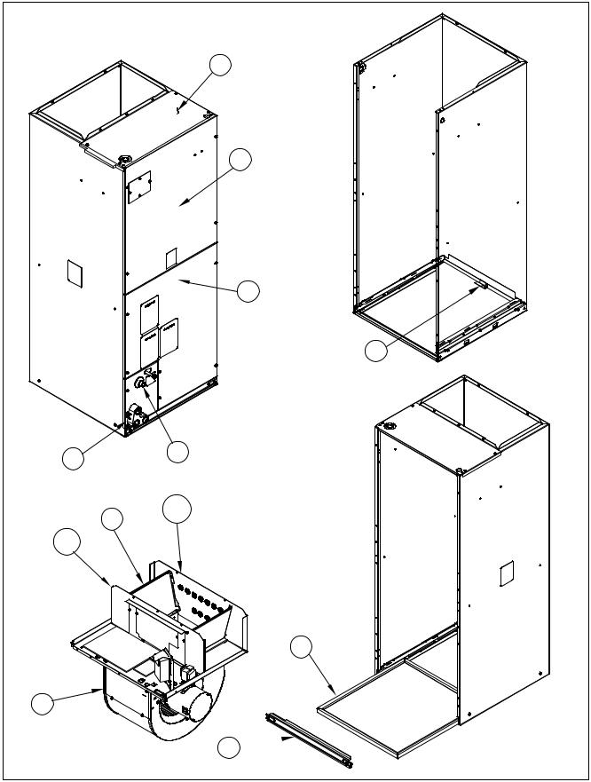
NOTE: This illustration is for reference only. Your unit may
differ in appearance or may not include all components shown.
D
G
AA
1
FEM4P, FSM4P, FSU4P
A
C
B
H
K
BB
5
E 
8 |
496 04 5500 01 |
 Loading...