


INSTALLATION INSTRUCTIONS
14 SEER R-410A Single-Package Air Conditioner
Single Phase 2 to 5 Nominal Tons PAJ4, WJA4
IMPORTANT: Effective January 1, 2015, all split system and packaged air conditioners must be installed pursuant to applicable regional efficiency standards issued by the Department of Energy.
NOTE: Read the entire instruction manual before starting the installation.
NOTE: Installer: Make sure the Owner’s Manual and Service |
|
Instructions are left with the unit after installation. |
|
TABLE OF CONTENTS |
|
|
PAGE |
SAFETY CONSIDERATIONS . . . . . . . . . . . . . . . . . . . . . |
. . . . 2 |
INTRODUCTION . . . . . . . . . . . . . . . . . . . . . . . . . . . . . . . |
. . . . 2 |
RECEIVING AND INSTALLATION . . . . . . . . . . . . . . . . |
. 2-10 |
Check Equipment . . . . . . . . . . . . . . . . . . . . . . . . . . . . . . |
. . . . 2 |
Identify Unit . . . . . . . . . . . . . . . . . . . . . . . . . . . . . . . . |
. . . . 2 |
Inspect Shipment . . . . . . . . . . . . . . . . . . . . . . . . . . . . . |
. . . . 2 |
Provide Unit Support . . . . . . . . . . . . . . . . . . . . . . . . . . . |
. . . . 2 |
Slab Mount . . . . . . . . . . . . . . . . . . . . . . . . . . . . . . . . . |
. . . . 2 |
Ground Mount . . . . . . . . . . . . . . . . . . . . . . . . . . . . . . |
. . . . 2 |
Provide Clearances . . . . . . . . . . . . . . . . . . . . . . . . . . . . . |
. . . . 2 |
Place Unit . . . . . . . . . . . . . . . . . . . . . . . . . . . . . . . . . . . . |
. . . . 2 |
Select and Install Ductwork . . . . . . . . . . . . . . . . . . . . . . . |
. . . . 3 |
Installing factory-supplied duct flanges . . . . . . . . . . . |
. . . . 3 |
Configuring Units for Downflow (Vertical) Discharge |
. . . . 9 |
Connect Condensate Drain . . . . . . . . . . . . . . . . . . . . . . . |
. . . . 9 |
Install Electrical Connections . . . . . . . . . . . . . . . . . . . . . |
. . . . 9 |
High-Voltage Connections . . . . . . . . . . . . . . . . . . . . . |
. . . . 9 |
Routing Power Leads Into Unit . . . . . . . . . . . . . . . . . . |
. . . . 9 |
Connecting Ground Lead to Unit Ground . . . . . . . . . . |
. . . . 9 |
Routing Control Power Wires . . . . . . . . . . . . . . . . . . |
. . . 10 |
Accessory Electric Heat Wiring . . . . . . . . . . . . . . . . . . |
. . . 10 |
PRE-START-UP . . . . . . . . . . . . . . . . . . . . . . . . . . . . . . . . |
. . . 10 |
START-UP . . . . . . . . . . . . . . . . . . . . . . . . . . . . . . . . . . . . . |
11-17 |
Check for Refrigerant Leaks . . . . . . . . . . . . . . . . . . . . . . |
. . . 11 |
Start-Up Cooling and Make Adjustments . . . . . . . . . . . . |
. . . 11 |
Checking Cooling and Heating Control Operation . . . |
. . . 11 |
Refrigerant Charge . . . . . . . . . . . . . . . . . . . . . . . . . . . . . |
. . . 13 |
No Charge . . . . . . . . . . . . . . . . . . . . . . . . . . . . . . . . . . |
. . . 13 |
Low Charge Cooling . . . . . . . . . . . . . . . . . . . . . . . . . . |
. . . 13 |
Indoor Airflow and Airflow Adjustments . . . . . . . . . . . . |
. . . 13 |
Sequence of Operation . . . . . . . . . . . . . . . . . . . . . . . . . . |
. . . 13 |
Fan Operation . . . . . . . . . . . . . . . . . . . . . . . . . . . . . . . |
. . . 13 |
Cooling Operation . . . . . . . . . . . . . . . . . . . . . . . . . . . . |
. . . 13 |
Continuous Fan . . . . . . . . . . . . . . . . . . . . . . . . . . . . . . |
. . . 17 |
Electric Resistance Heating . . . . . . . . . . . . . . . . . . . . . |
. . . 17 |
A10165
Fig. 1 - Unit PAJ4, WJA4
Certified to leak 2% or less of nominal air conditioning CFM delivered when pressurized to 1-in. W.C. with all present air inlets, air outlets, and condensate drain port(s) sealed.
MAINTENANCE . . . . . . . . . . . . . . . . . . . . . . . . . . . . . . . . 18-21 Air Filter . . . . . . . . . . . . . . . . . . . . . . . . . . . . . . . . . . . . . . . . 18 Unit Top Removal . . . . . . . . . . . . . . . . . . . . . . . . . . . . . . . . . 18 Indoor Blower and Motor . . . . . . . . . . . . . . . . . . . . . . . . . . . 18 Outdoor Coil, Indoor Coil, and Condensate Drain Pan . . . . . 19 Outdoor Fan Adjustment . . . . . . . . . . . . . . . . . . . . . . . . . . . . 19 Electrical Controls and Wiring . . . . . . . . . . . . . . . . . . . . . . . 19 Refrigerant Circuit . . . . . . . . . . . . . . . . . . . . . . . . . . . . . . . . . 20 Indoor Airflow . . . . . . . . . . . . . . . . . . . . . . . . . . . . . . . . . . . 20 Metering Devices . . . . . . . . . . . . . . . . . . . . . . . . . . . . . . . . . 20 High Flow Valves . . . . . . . . . . . . . . . . . . . . . . . . . . . . . . . . . 20 High Pressure Switch . . . . . . . . . . . . . . . . . . . . . . . . . . . . . . 20 R-410A Compressor . . . . . . . . . . . . . . . . . . . . . . . . . . . . . . . 20 Refrigerant . . . . . . . . . . . . . . . . . . . . . . . . . . . . . . . . . . . . . . 20 Compressor Oil . . . . . . . . . . . . . . . . . . . . . . . . . . . . . . . . . . . 20 Servicing Systems on Roof with Synthetic Materials . . . . . . 20 Synthetic Roof Precautionary Procedure . . . . . . . . . . . . . . . . 21 Liquid Line Filter Drier . . . . . . . . . . . . . . . . . . . . . . . . . . . . . 21 R-410A Refrigerant Charging . . . . . . . . . . . . . . . . . . . . . . . 21
TROUBLESHOOTING . . . . . . . . . . . . . . . . . . . . . . . . . . . . . . 21 START-UP CHECKLIST . . . . . . . . . . . . . . . . . . . . . . . . . . . . 21
Specifications are subject to change without notice.
426 01 1707 01 03/2015
PAJ4, WJA4
SAFETY CONSIDERATIONS
Installation and servicing of this equipment can be hazardous due to mechanical and electrical components. Only trained and qualified personnel should install, repair, or service this equipment.
Untrained personnel can perform basic maintenance functions such as cleaning and replacing air filters. All other operations must be performed by trained service personnel. When working on this equipment, observe precautions in the literature, on tags, and on labels attached to or shipped with the unit and other safety precautions that may apply.
Follow all safety codes. Wear safety glasses, protective clothing, and work gloves. Use quenching cloth for brazing operations. Have fire extinguisher available. Read these instructions thoroughly and follow all warnings or cautions included in literature and attached to the unit. Consult local building codes, the current editions of the National Electrical Code (NEC) NFPA 70 and NFPA 90B-Installation Warm Air Heating and A/C Systems (Residential). In Canada refer to the current editions of the Canadian Electrical Code CSA C22.1.
Recognize safety information. This is the safety-alert symbol  . When you see this symbol on the unit and in instructions or manuals, be alert to the potential for personal injury. Understand these signal words: DANGER, WARNING, and CAUTION. These words are used with the safety-alert symbol. DANGER identifies the most serious hazards which will result in severe personal injury or death. WARNING signifies hazards which could result in personal injury or death. CAUTION is used to identify unsafe practices which may result in minor personal injury or product and property damage. NOTE is used to highlight suggestions which will result in enhanced installation, reliability, or operation.
!WARNING
ELECTRICAL SHOCK HAZARD
Failure to follow this warning could result in personal injury or death.
Before installing or servicing system, always turn off main power to system and install lockout tag. There may be more than one disconnect switch. Turn off accessory heater power switch if applicable.
!CAUTION
CUT HAZARD
Failure to follow this caution may result in personal injury.
Sheet metal parts may have sharp edges or burrs. Use care and wear appropriate clothing, safety glasses and gloves when handling parts, and servicing equipment.
!WARNING
PERSONAL INJURY AND ENVIRONMENTAL HAZARD
Failure to relieve system pressure could result in personal injury and/or death.
1. Relieve pressure and recover all refrigerant before servicing existing equipment, and before final unit disposal. Use all service ports and open all flow-control devices, including solenoid valves.
2. Federal regulations require that you do not vent refrigerant into the atmosphere. Recover during system repair or final unit disposal.
INTRODUCTION
The PAJ4 and WJA4 packaged air conditioners are fully self-contained and designed for outdoor installation (See Fig. 1). Standard units are shipped in a horizontal-discharge configuration for installation on a ground-level slab or directly on the ground, if local codes permit. Standard units can be converted to downflow (vertical) discharge configurations for rooftop applications with a field supplied plenum.
RECEIVING AND INSTALLATION
Step 1 — Check Equipment
IDENTIFY UNIT
The unit model number and serial number are printed on the unit informative plate. Check this information against shipping papers.
INSPECT SHIPMENT
Inspect for shipping damage while unit is still on shipping pallet. If unit appears to be damaged or is torn loose from its anchorage, have it examined by transportation inspectors before removal. Forward claim papers directly to transportation company. Manufacturer is not responsible for any damage incurred in transit. Check all items against shipping list. Immediately notify the nearest equipment distribution office if any item is missing. To prevent loss or damage, leave all parts in original packages until installation.
Step 2 — Provide Unit Support
For hurricane tie downs, contact distributor for details and PE (Professional Engineering) Certificate, if required.
SLAB MOUNT
Place the unit on a solid, level concrete pad that is a minimum of 4 in. (101.6 mm) thick with 2 in. (50.8 mm) above grade. The slab should extend approximately 2 in. (50.8 mm) beyond the casing on all 4 sides of the unit. Do not secure the unit to the slab except when required by local codes.
A 6-in. (152.4 mm) wide gravel apron should be used around the flat surface to prevent airflow blockage by grass or shrubs. The unit should be level within 1/4 in. (6.4 mm). This is necessary for the unit drain to function properly.
GROUND MOUNT
The unit may be installed either on a slab or placed directly on the ground if local codes permit. Place the unit on level ground prepared with gravel for condensate discharge.
Step 3 — Provide Clearances
The required minimum service clearances are shown in Fig. 4 and Fig. 5. Adequate ventilation and outdoor air must be provided.
The outdoor fan draws air through the outdoor coil and discharges it through the top fan grille. Be sure that the fan discharge does not recirculate to the outdoor coil. Do not locate the unit in either a corner or under an overhead obstruction. The minimum clearance under a partial overhang (such as a normal house overhang) is 48 in. (1219 mm) above the unit top. The maximum horizontal extension of a partial overhang must not exceed 48 in. (1219 mm).
IMPORTANT: Do not restrict outdoor airflow. An air restriction at either the outdoor-air inlet or the fan discharge may be detrimental to compressor life.
Do not place the unit where water, ice, or snow from an overhang or roof will damage or flood the unit. Do not install the unit on carpeting or other combustible materials. Slab-mounted units should be at least 4 in. (102 mm) above the highest expected water and runoff levels. Do not use unit if it has been under water.
Step 4 — Place Unit
Unit can be moved with the rigging holds provided in the unit base. Refer to table 1 for shipping weights. Use extreme caution to prevent damage when moving the unit. Unit must remain in an upright position during all moving operations. The unit must be level with in 1/4 in. (6.4 mm) for proper condensate drainage; the
2 |
Specifications are subject to change without notice. |
42601170701 |
ground-level pad must be level before setting the unit in place. When a field-fabricated support is used, be sure that the support is level and that it properly supports the unit.
Step 5 — Select and Install Ductwork
The design and installation of the duct system must be in accordance with the standards of the NFPA for installation of non-residence type air conditioning and ventilating systems, NFPA 90A or residence type, NFPA 90B and/or local codes and ordinances.
Select and size ductwork, supply-air registers, and return air grilles according to ASHRAE (American Society of Heating, Refrigeration, and Air Conditioning Engineers) recommendations.
Use the duct flanges provided on the supplyand return-air openings on the side of the unit. See Fig. 4 and Fig. 5 for connection sizes and locations. The 14-in. (356 mm) round or 14 x 20 in. (356 x 508mm) rectangular duct collars are shipped inside the unit attached to the base pan in the indoor blower compartment. They are field-installed and must be removed from the indoor blower compartment prior to start-up, even if they are not used for installation. If a corrugated shipping block is used under the blower housing, remove and discard the block and label.
When designing and installing ductwork, consider the following:
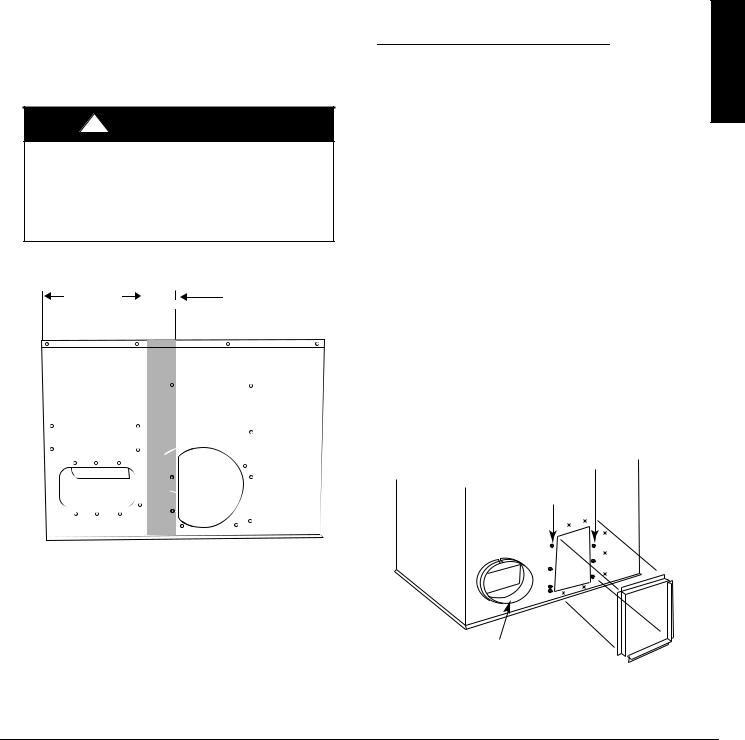
!CAUTION
UNIT DAMAGE HAZARD
Failure to follow this caution may result in damage to unit components.
When connecting ductwork to units, do not drill deeper than 3/4 in. (19.1 mm) in shaded area shown in Fig. 2 or coil may be damaged.
19.17 in. |
3.92 in. |
|
(487 mm) |
(100 mm) |
|
|
|
|
|
|
|
|
|
|
A10021
Fig. 2 - Area Not to be Drilled More Than 3/4-in. (19.1 mm) Deep
1.All units should have field-supplied filters installed in the return-air side of the unit. Recommended sizes for filters are shown in Table 1.
2.Avoid abrupt duct size increases and reductions. Abrupt change in duct size adversely affects air performance.
IMPORTANT: Use flexible connectors between ductwork and unit to prevent transmission of vibration. Use suitable gaskets to ensure weather tight and airtight seal. When electric heat is installed, use fireproof canvas (or similar heat resistant material) connector between ductwork and unit discharge connection. If
flexible duct is used, insert a sheet metal sleeve inside duct. Heat resistant duct connector (or sheet metal sleeve) must extend 24-in. (610 mm) from electric heater element.
3.Size ductwork for cooling air quantity (cfm). The minimum air quantity for proper electric heater operation is listed in Table 2. Heater limit switches may trip at air quantities below those recommended.
4.Seal, insulate, and weatherproof all external ductwork. Seal, insulate and cover with a vapor barrier all ductwork passing through conditioned spaces. Follow latest Sheet Metal and Air Conditioning Contractors National Association (SMACNA) and Air Conditioning Contractors Association (ACCA) minimum installation standards for residential heating and air conditioning systems.
5.Secure all ducts to building structure. Flash, weatherproof, and vibration-isolate duct openings in wall or roof according to good construction practices.
Fig. 8 shows a typical duct system with unit installed.
Installing factory-supplied duct flanges;
For 24, 30, and 36 sizes:
S Two round 14-in. (356 mm) duct collars are factory supplied.
SLine up the 6 holes in the duct collar with the pre-drilled holes in the side panel.
S Fasten duct collar to side panel using field-supplied screws.
For 42, 48, and 60 sizes (See Fig. 3):
S One round 14-in. (356 mm) duct collar for the supply air connections and two “L” brackets for the 14-in. x 20-in. (356 x 508 mm) return air connection are factory-supplied.
SLine up the 6 holes in the supply duct collar with the pre-drilled holes in the side panel. Fasten duct collar to side panel using field-supplied screws.
SFor the return, remove the 4 screws on the left side of the return and install one of the “L” flanges on the left side by replacing the 4 screws. Using the 2 dimples below the return, align the bottom of the “L” flange with the two dimples and attach using filed-supplied thread-cutting screws.
For the second “L” flange, align flange with the three dimples to the right of the return and the two dimples above the return and attach using field-supplied thread-cutting screws.
NOTE: The factory-installed screws to the right of the return should not be removed in this process.
3 Factory Installed Screws (Must not be removed)
Remove 4 screws from left side of duct opening and reuse to install the left half of duct flange.
Install supply duct flange as shown into existing holes with field-supplied screws.
X = Factory dimples for duct flange attachment.
A10081
Fig. 3 - Installing Factory-Supplied Duct Flanges
PAJ4, WJA4
42601170701 |
Specifications are subject to change without notice. |
3 |

PAJ4, WJA4
A14411
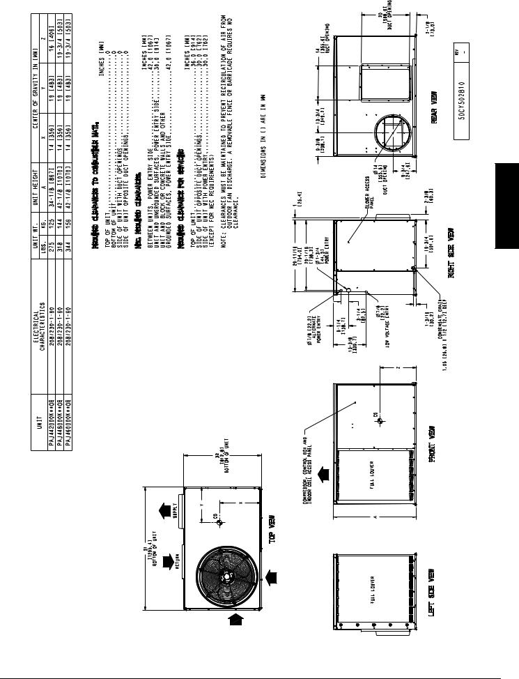
Fig. 4 - Unit Base Dimensions, PAJ4 024-036
4 |
Specifications are subject to change without notice. |
42601170701 |
PAJ4, WJA4 |
A14412
Fig. 5 - Unit Base Dimensions, PAJ4 042-060
42601170701 |
Specifications are subject to change without notice. |
5 |
PAJ4, WJA4
A14446
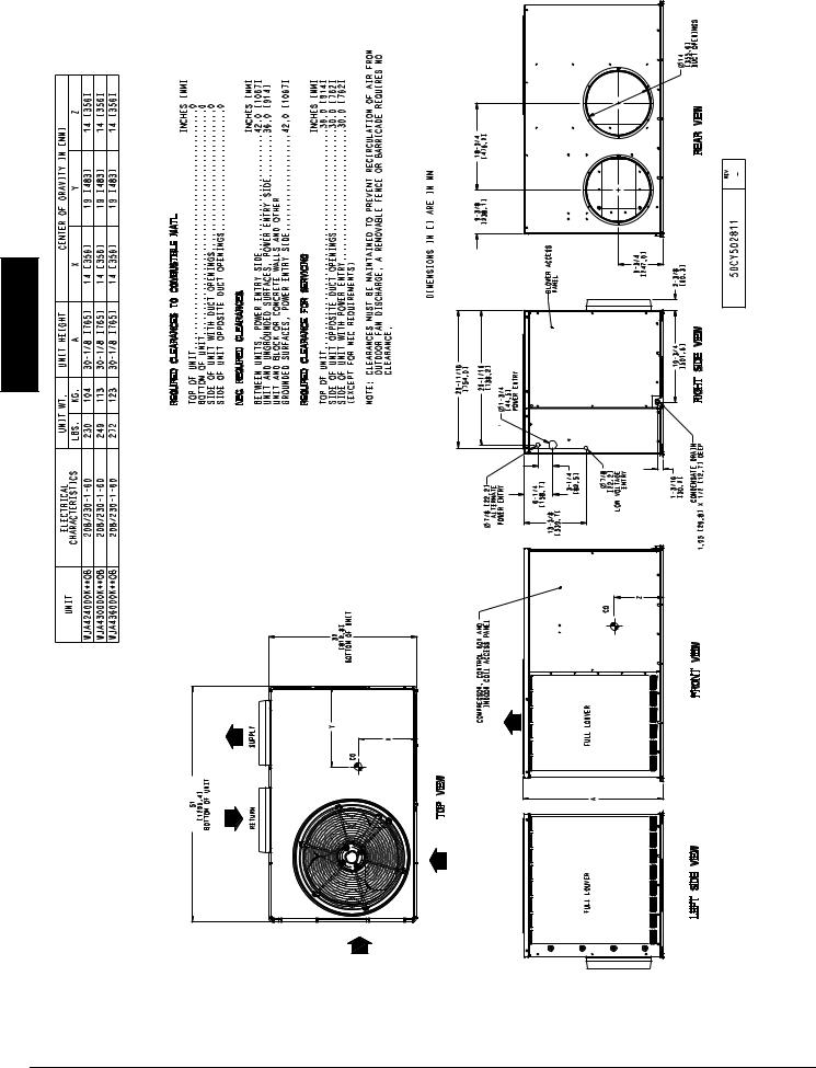
Fig. 6 - Unit Base Dimensions, WJA4 024-036
6 |
Specifications are subject to change without notice. |
42601170701 |
 Loading...