

Page 1
®
Intel
NetStructure
Switch
Quick Start
™
6000
Page 2

Copyright © 2000, Intel Corporation. All rights reserved.
Intel Corporation, 5200 NE Elam Young Parkway, Hillsboro OR 97124-6497
I
nformation in this document is provided in connection with Intel® products. No license, express or
implied, by estoppel or otherwise, to any intellectual property rights is granted by this document. Except as
provided in Intel's Terms and Conditions of Sale for such products, Intel assumes no liability whatsoever,
and Intel disclaims any express or implied warranty, relating to sale and/or use of Intel products including
liability or warranties relating to fitness for a particular purpose, merchant ability, or infringement of any
patent, copyright or other intellectual property right. Intel products are not intended for use in medical, life
saving, or life sustaini ng app licati on s. Int el m ay mak e chan ges t o s pecificat i ons and product descriptions at
any time, without notice.
*Other product and corporate names may be trademarks of other companies and are used only for explanation and to the
owners’ benefit, without intent to infringe.
First Edition May 2000 A19062-001
Page 3
Quick Start
1
2
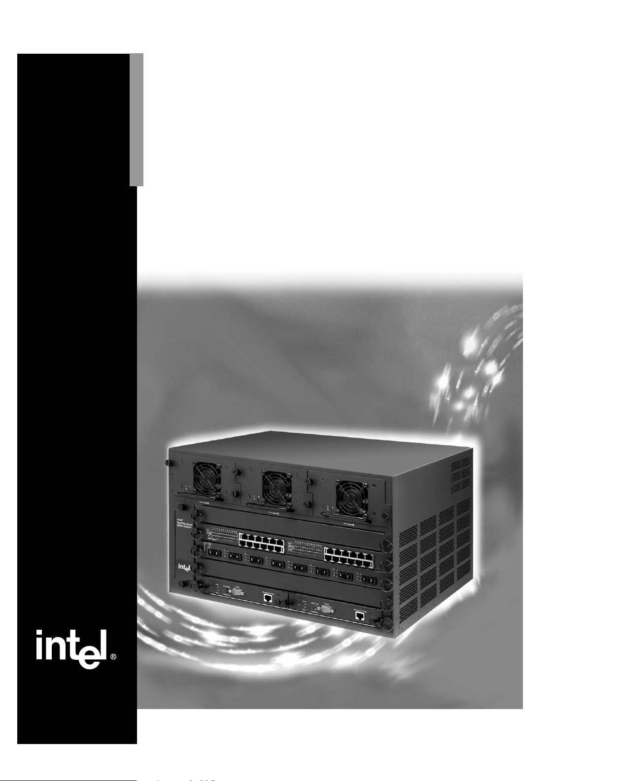
Set up the switch
For complete installa t ion r equi r e ment s ,
see the User Guide.
1 Remove the switch and parts from the
box.
2 If you plan to install the switch in a 19 -
inch rack, remove the four front panel
screws on each side of the unit, then use
the screws included in the accessory kit
to fasten the rack-mount brackets.
3 Install the switch in a rack or on a shelf.
Install the carrier
tray module
1 Slide the carrier tray module into Slot 5
(the bottom slot) until it meets the connector inside the chassis, and the capture
panel screws engage the chassis.
2 Tighten both capture panel screws
simultaneously.
Gender
Adapter Bar
Front Panel Screws
Slot 5
Carrier Tray
3
Install the Control
Processor module
1 Slide the Control Processor (CP) mod-
ule into the left side of the carrier tray.
2 Push the module back until it meets the
connector inside the chassis, and the
capture panel screws engage the carrier
tray.
3 Tighten both capture panel screws
simultaneously.
4 If you ordered a second module, remo ve
the face plate on the right side of the
bottom slot and follow the instru ctions
above to install the module.
Slot 5
Primary CP
Page 4

4
5
Install additional
power supplies
If you purchased an addition al power supply, place it in one of the empty power
supply bays at the top of the chassis.
1 Loosen and remove the capture panel
screws on the face plate of the power
supply bay.
2 Push the power supply into the power
supply bay until the capture panel
screws engage the chassis.
3 Tighten the capture panel screws.
ActInstall the
network modules
You can install network modules, such as
the 1000Base-SX, 1000BaseLX /
1000BaseSX and 10/100Base -TX, in any
available slot on the chassis
1 Remove the filler panels from any slots
(1-4) that will hold network modules.
2 Push the module back until it conn ects
with the backplane connector, and the
capture panel screws engage the chassis.
3 Tighten both capture panel screws
simultaneously.
4 Leave the filler panels in any unused
slots. Doing so keeps dust out of the
switch and helps maintain p r oper airflow.
Capture Panel
Screws
Gigabit
Ethernet
Module
2
Page 5

6
7
Plug in the switch
After you’ve installed all modules, plug
power cords into each installed power supply at the back of the chassis.
Back Panel
Connect to devices
After you have powered on the switch,
plug in the network cables.
Use the network module LEDs to verify
link status and activity.
See the User Guide for more information
on network cabling and LED usage.
LEDs
3
Page 6

Management Options
Configure and
8
Option 1: Local Management
1 Connect your PC directly to the Console port on
2 Set a VT-100-compatible terminal emulation
3 At the Password prompt, press Enter. By
4 Configure IP settings:
The IP address allows you to access and manage the
switch using a Web browser or Telnet application.
manage the switch
the Control Processor module using the
included null modem cable.
program (such as HyperTerminal*) to these
parameters:
- 9600 baud - 8 data bits
- No parity - 1 stop bit
default, no password is set. See the User Guide
for information on setting passwords.
At the prompt, type
ifconfig et0 [x.x.x.x] netmask [y.y.y.y]
• The out-of-band port or management port on
the front of the CP is identified as interface
et0.
• [x.x.x.x] is the IP address yo u want to assign
to the switch.
• [y.y.y.y] is the subnet mask you want to
assign to the switch.
Note: In-band through the switched ports is identified by interfaces sw1 through sw4093
and are assigned for each VLAN configured to use IP.
For example
out-of-band
in-band
Enter the following commands on a single line.
See the User Guide for complete information on
using Local Management and configuring VLANs.
4
ifconfig et0 134.134.34.122 netmask 255.255.0.0
ifconfig sw1 134.134.34.122 netmask 255.255.0.0
Page 7
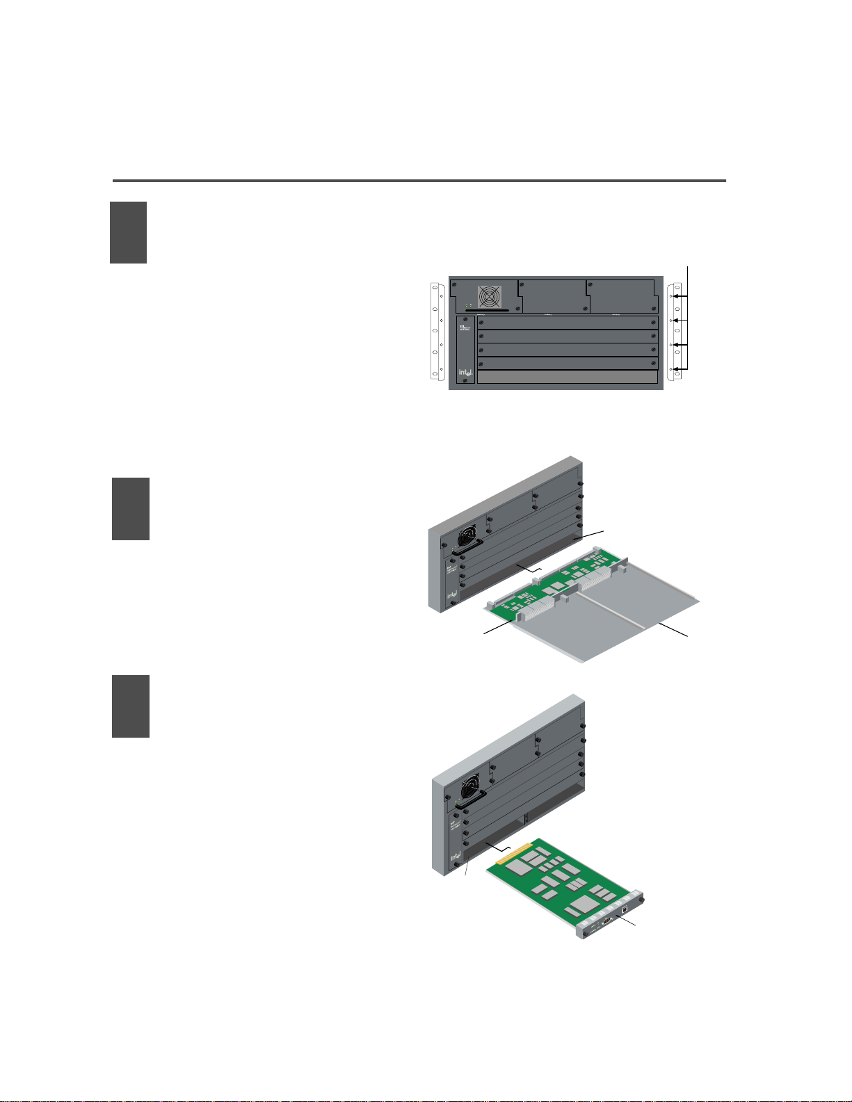
Option 2: Intel® Device View
Use Intel® Device View if you want to manage
other Intel devices (such as hubs or switches) in
addition to the Intel NetStructure™ 6000 Switch.
For Intel Device View, use the following software:
Intel Device View
(Windows)
Intel Device View
(Web)
Browser - Internet Explorer 4.0 or
OS - Windows NT 4.0
Web Server - IIS 2.0 or later
1 Place the CD-ROM in the computer’s CD-ROM
drive. Select the Windows* or Web version and
follow the on-screen instructions in the Intel
Device View installation wizard.
2 Start Intel Device View.
• Windows: After installation, the program
automatically restarts the computer (if necessary) and launches the Device Install
wizard. Follow the on-screen instructions.
Web: After installing on a PC with a Web
server, (see table above for requirements)
double-click the Intel Device View icon to
run the program. The MAC address of the
new switch appears under Unconfigured
Devices in the SNMP Device Tree. Doubleclick the MAC address to assign an IP
address to the switch.
T o vi ew Inte l Dev ice View from anot her P C
on your network, type the following URL in
Internet Explorer’s Address field:
http://
servername
where servername is the IP address or name
of the Intel Device View server.
For more information on Intel Device View, see the
User Guide on the Intel Device View CD-ROM.
- Windows* 95 or 98
- Windows NT* 4.0
later
- Windows 95 or 98
- Peer Web Services
- Netscape Enterprise*
Web Server 3.01 or later
/devview/main.htm
Intel Device View allows you to manage Intel
hubs, routers, and switches from a single PC
or any PC using Internet Explorer 4.0x or
later.
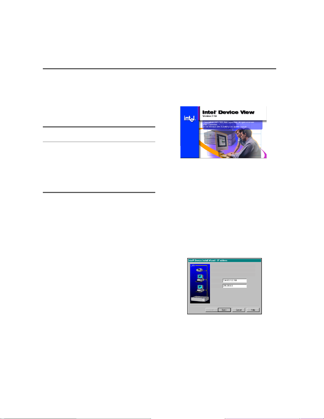
Assign an IP address to the Intel NetStructure 6000 Switch
1. IP address (partly filled out by the wizard)
2. Subnet mask (filled out by the wizard)
IP Address:
__
Subnet Mask:
__
Intel Device View’s Install Wizard detects and
allows you to configure the 6000 Switch.
5
Page 8

Option 3: Web Device Manager
Before you can use the Web Device Manager, you
must configure the switch’s IP settings. See the
Local Management or Intel Device View sections
for more information.
1 Open your Web browser. The Web Device Man-
ager supports Internet Expl orer* 4. 0x or later or
Navigator* 4.0x or later.
2 Type the switch’s IP address in the Address (or
Location) field, then press Enter.
3 When prompted for a user name and password,
type the privileged name “priv” and password
you set using Local Management, then press
Enter.
Note: “priv” is the default name.
4 Click the menus on the left side of the window
to display configuration and managem e nt
options.
6
 Loading...