

Page 1

AV Receiver
Contents
Before using
Important Safeguards.......................... 2
Precautions ........................................... 3
Features.................................................4
Supplied accessories ...........................4
DTM-5.3
Instruction Manual
Thank you for purchasing the Integra AV Receiver.
Please read this manual thoroughly before making connections and plugging in the unit.
Following the instructions in this manual will
enable you to obtain optimum performance and
listening enjoyment from your new AV Receiver.
Please retain this manual for future reference.
Facilities and connections
Remote controller description ............5
Front panel description........................6
Rear panel description ........................8
Connecting components .................10
Connecting speakers ........................12
Connecting antennas ....................... 13
Connecting the remote zone
(Zone 2) ............................................14
Operating components not
reached by the remote
controller signals (IR IN/OUT) ..........15
Connecting the power...................... 16
Installing the remote controller
batteries ...........................................17
Setup and operation
Basic operations .................................18
Receiving stations ..............................20
Entering station names ...................... 23
Recording a source ...........................24
Using Tape 2 Monitor .........................26
Enjoying music in the remote zone
Remote controller
Using the remote controller...............28
Controlling other components ......... 29
...27
Appendix
Troubleshooting guide....................... 31
Specifications ..........back cover page
Page 2
1.
Before using
WARNING:
TO REDUCE THE RISK OF FIRE OR ELECTRIC SHOCK,
DO NOT EXPOSE THIS APPLIANCE TO RAIN OR
MOISTURE.
CAUTION:
TO REDUCE THE RISK OF ELECTRIC SHOCK, DO NOT
REMOVE COVER (OR BACK). NO USER-SERVICEABLE
PARTS INSIDE. REFER SERVICING TO QUALIFIED
SERVICE PERSONNEL.
Important Safeguards
Read Instructions – All the safety and operating instructions
should be read before the appliance is operated.
2.
Retain Instructions
should be retained for future reference.
3.
Heed Warnings
operating instructions should be adhered to.
4.
Follow Instructions
should be followed.
5.
Cleaning
cleaning. The appliance should be cleaned only as recommended by the manufacturer.
6.
Attachments
facturer may create hazards. Use only recommended attachments.
7. Water and Moistur e – Do not use the appliance near water –for
example, near a bath tub, wash bowl, kitchen sink, or laundry
tub; in a wet basement; or near a swimming pool; and the like.
8. Accessories – Do not place the appliance on an unstable cart,
stand, tripod, bracket, or table.The appliance may fall, causing
serious injury to a child or adult, and serious damage to the
appliance. Use only with a cart, stand, tripod, bracket, or table
recommended by the manufacturer, or sold with the appliance.
Any mounting of the appliance should follow the manufacturer’s instructions, and
should use a mounting accessory recommended by the manufacturer.
9. An appliance and cart combination should
be moved with care. Quick stops, excessive
force, and uneven surfaces may cause the
appliance and cart combination to overturn.
10.
Ventilation
for ventilation and to ensure reliable operation of the appliance
and to protect it from overheating, and these openings must not
be blocked or covered. The openings should never be blocked
by placing the appliance on a bed, sofa, rug, or other similar
surface. The appliance should not be placed in a built-in installation such as a bookcase or rack unless proper ventilation is
provided. There should be free space of at least 20 cm (8 in.)
and an opening behind the appliance.
11.
Power Sources
the type of power source indicated on the marking label. If you
are not sure of the type of power supply to your home, consult
your appliance dealer or local power company.
12.
Grounding or Polarization
with a polarized alternating current line plug (a plug having
one blade wider than the other). This plug will fit into the
power outlet only one way. This is a safety feature. If you are
unable to insert the plug fully into the outlet, try reversing the
plug. If the plug should still fail to fit, contact your electrician
to replace your obsolete outlet. Do not defeat the safety purpose of the polarized plug.
– Unplug the appliance from the wall outlet before
– Slots and openings in the cabinet are provided
– The safety and operating instructions
– All warnings on the appliance and in the
– All operating and usage instructions
– Attachments not recommended by the manu-
PORTABLE CART WARNING
S3125A
– The appliance should be operated only from
– The appliance may be equipped
WARNING
RISK OF ELECTRIC SHOCK
DO NOT OPEN
The lightning flash with arrowhead symbol, within an equilateral
triangle, is intended to alert the user to the presence of uninsulated
“dangerous voltage” within the product’s enclosure that may be of
sufficient magnitude to constitute a risk of electric shock to persons.
The exclamation point within an equilateral triangle is intended to
alert the user to the presence of important operating and maintenance
(servicing) instructions in the literature accompanying the appliance.
13.
Power-Cord Protection
routed so that they are not likely to be walked on or pinched by
items placed upon or against them, paying particular attention
to cords at plugs, convenience receptacles, and the point at
which they exit from the appliance.
14.
Outdoor Antenna Grounding
system is connected to the appliance, be sure the antenna or
cable system is grounded so as to provide some protection
against voltage surges and built-up static charges. Article 810
of the National Electrical Code, ANSI/NFPA 70, provides
information with regard to proper grounding of the mast and
supporting structure, grounding of the lead-in wire to an
antenna-discharge unit, size of grounding conductors, location
of antenna-discharge unit, connection to grounding electrodes,
and requirements for the grounding electrode. See Figure 1.
15.
Lightning
lightning storm, or when it is left unattended and unused for
long periods of time, unplug it from the wall outlet and disconnect the antenna or cable system. This will prevent damage to
the appliance due to lightning and power-line surges.
16.
Power Lines
located in the vicinity of overhead power lines or other electric
light or power circuits, or where it can fall into such power
lines or circuits. When installing an outside antenna system,
extreme care should be taken to keep from touching such
power lines or circuits as contact with them might be fatal.
17.
Overloading
or integral convenience receptacles as this can result in a risk of
fire or electric shock.
18.
Object and Liquid Entry
into the appliance through openings as they may touch dangerous voltage points or short-out parts that could result in a fire or
electric shock. Never spill liquid of any kind on the appliance.
19. Servicing – Do not attempt to service the appliance yourself as
opening or removing covers may expose you to dangerous voltage
or other hazards. Refer all servicing to qualified service personnel.
20. Damage Requiring Service – Unplug the appliance form the
wall outlet and refer servicing to qualified service personnel
under the following conditions:
A. When the power-supply cord or plug is damaged
B. If liquid has been spilled, or objects have fallen into the
C. If the appliance has been exposed to rain or water
D. If the appliance does not operate normally by following the
E. If the appliance has been dropped or damaged in any w ay, and
F. When the appliance exhibits a distinct change in perfor-
– For added protection for the appliance during a
– An outside antenna system should not be
– Do not overload wall outlets, extension cords,
appliance
operating instructions. Adjust only those controls that are
covered by the operating instructions as an improper adjustment of other controls may result in damage and will often
require extensive work by a qualified technician to restore
the appliance to its normal operation.
mance – this indicates a need for service.
– Power-supply cords should be
AVIS
RISQUE DE CHOC ELECTRIQUE
– Never push objects of any kind
OUVRIR
NE PAS
– If an outside antenna or cable
2
Page 3

21. Replacement Parts – When replacement parts are required, be
sure the service technician has used replacement parts specified
by the manufacturer or that have the same characteristics as the
original part. Unauthorized substitutions may result in fire,
electric shock, or other hazards.
22.
Safety Check
the appliance, ask the service technician to perform safety
checks to determine that the appliance is in proper operating
condition.
23.
Wall or Ceiling Mounting
to a wall or ceiling only as recommended by the manufacturer.
24.
Heat
– The appliance should be situated away from heat
sources such as radiators, heat registers, stoves, or other appliances (including amplifiers) that produce heat.
25.
Liquid Hazards
ping or splashing and no objects filled with liquids, such as
vases shall be placed on the appliance.
– Upon completion of any service or repairs to
– The appliance should be mounted
– The appliance shall not be exposed to drip-
Precautions
1. Recording Copyright
Recording of copyrighted material for other than personal use is
illegal without permission of the copyright holder.
2. AC Fuse
The fuse is located inside the chassis and is not user-serviceable. If
power does not come on, contact your Integra/Onkyo authorized
service station.
3. Care
From time to time you should wipe the front and rear panels and
the cabinet with a soft cloth. For heavier dirt, dampen a soft cloth
in a weak solution of mild detergent and water, wring it out dry,
and wipe off the dirt. Following this, dry immediately with a clean
cloth. Do not use rough material, thinners, alcohol or other chemical solvents or cloths since these could damage the finish or remove
the panel lettering.
4. Power
WARNING
BEFORE PLUGGING IN THE UNIT FOR THE FIRST TIME,
READ THE FOLLOWING SECTION CAREFULLY.
The voltage of the available power supply differs according to
country or region. Be sure that the power supply voltage of the area
in which this unit will be used meets the required voltage (e.g., AC
120 V, 60 Hz) written on the rear panel.
Setting the Standby/On button to standby does not shut off the
power completely. The power cord should be remov ed from the A C
outlet when the unit is not used for a prolonged period of time.
For U.S. model
Note to CATV system installer:
This reminder is provided to call the CATV system installer's attention to Section 820-40 of the NEC which provides guidelines for
proper grounding and, in particular, specifies that the cable ground
shall be connected to the grounding system of the building, as close
to the point of cable entry as practical.
FIGURE 1:
EXAMPLE OF ANTENNA GROUNDING AS PER NATIONAL
ELECTRICAL CODE, ANSI/NFPA 70
ANTENNA
LEAD IN
WIRE
GROUND
CLAMP
ANTENNA
DISCHARGE UNIT
(NEC SECTION 810-20)
ELECTRIC
SERVICE
EQUIPMENT
NEC – NATIONAL ELECTRICAL CODE
S2898A
GROUNDING CONDUCTORS
(NEC SECTION 810-21)
GROUND CLAMPS
POWER SERVICE GROUNDING
ELECTRODE SYSTEM
(NEC ART 250, PART H)
FCC Information for User
CAUTION:
The user changes or modifications not expressly approved by the
party responsible for compliance could void the user’s authority to
operate the equipment.
NOTE:
This equipment has been tested and found to comply with the limits
for a Class B digital device, pursuant to Part 15 of the FCC Rules.
These limits are designed to provide reasonable protection against
harmful interference in a residential installation. This equipment
generates, uses and can radiate radio frequency energy and, if not
installed and used in accordance with the instructions, may cause
harmful interference to radio communications. Howev er, there is no
guarantee that interference will not occur in a particular installation.
If this equipment does cause harmful interference to radio or television reception, which can be determined by turning the equipment
off and on, the user is encouraged to try to correct the interference
by one or more of the following measures:
• Reorient or relocate the receiving antenna.
• Increase the separation between the equipment and receiver.
• Connect the equipment into an outlet on a circuit different from
that to which the receiver is connected.
• Consult the dealer or an experienced radio/TV technician for
help.
For Canadian model
For models having a power cord with a polarized plug:
CAUTION:
WIDE BLADE OF PLUG TO WIDE SLOT, THEN FULLY INSERT.
NOTE:
WITH CANADIAN ICES-003.
Modèle pour les Canadien
Sur les modèles dont la fiche est polarisée:
ATTENTION:
TRIQUES, INTRODUIRE LA LAME LA PLUS LARGE DE LA
FICHE DANS LA BORNE CORRESPONDANTE DE LA PRISE
ET POUSSER JUSQU’AU FOND.
TO PREVENT ELECTRIC SHOCK, MATCH
THIS CLASS B DIGITAL APPARATUS COMPLIES
POUR ÉVITER LES CHOCS ÉLEC-
REMARQUE:
CLASSE B EST CONFORME À LA NORME NMB-003 DU
CANADA.
CET APPAREIL NUMÉRIQUE DE LA
3
Page 4
Features
■
Power output
100 watts per channel, min RMS, at 8 ohms, both
channels driven from 20 Hz to 20 kHz, with no more
than 0.08% THD
■
Discrete output stage circuits for true high-current,
low-impedance drive
■
Costly, high-quality parts such as large power transistors, an oversized isolated transformer and heavyduty extruded heat sink make it possible to accurately
and effortlessly drive 4-ohm speakers (rare for a
receiver)
A-BUS Ready
■
■
4 Audio and 2 AV inputs
■
A-B Speaker selector and outputs
Video and cassette tape dubbing capability
■
■
Direct tone control
■
40 FM/AM random presets
Preset scan tuning
■
■
Direct access tuning
■
Motor-driven, precision volume control
Headphone jack
■
■
Audio mute, sleep timer (via remote)
■
Battery-free rotary volume knob
New non-resonant feet
■
■
New slip-free rotary volume knob
■
Compatible remote control
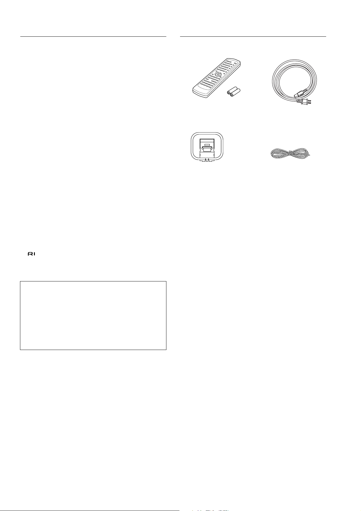
Supplied accessories
Check that the following accessories are supplied with the DTM-5.3.
Remote controller RC-477S (1)
Batteries (AA, R6 or UM-3) (2)
AM loop antenna (1) FM indoor antenna (1)
Power cord (1)
Memory Preservation
This unit does not require memory preservation batteries. A built-in
memory power back-up system preserves the contents of the memory during power failures and even when the unit is unplugged. The
unit must be plugged in order to charge the back-up system.
The memory preservation period after the unit has been unplugged
varies depending on climate and placement of the unit. On the average, memory contents are protected over a period of a few weeks
after the last time the unit has been unplugged. This period is
shorter when the unit is exposed to a highly humid climate.
4
Page 5

Facilities and connections
Remote controller description
Note: When you use the buttons that apply to specific mode
(i.e., DVD mode, RCVR/Tape mode, or CD mode), you must
press the corresponding mode button first.
Standby ( ) button
This button sets the unit to Standby mode.
On ( ) button
This button turns on the power to the unit.
Scan button
Press this button to scan the preset channels.
Preset buttons
These buttons enable you to select an FM/AM preset channel.
Number (1–9, 0/10) buttons
When using RCVR/Tape mode, use these buttons to program
and select the radio presets.
When using CD or DVD mode, use these buttons to select
tracks and chapters.
Alphabetic letters/symbols buttons (RCVR/Tape mode)
Use these buttons to name the preset channels using characters.
DRCT Tune (Direct Tuning) button (RCVR/Tape mode)
Use this button to set the frequency. After pressing this button, use the number buttons to input the frequency.
+10 button (CD or DVD mode)
This button is used as a numeric key to control the Integra/
Onkyo CD or DVD player connected by using the terminals.
Top Menu button (DVD mode)
Press this button to display the top menu screen of a DVD.
Memory button (RCVR/Tape mode)
This button enables you to program or erase preset FM/AM
stations.
/ / / / Enter buttons (DVD mode)
Use these cursor buttons to mov e the cursor to select an item on
the display, and press the Enter button to confirm the setting.
T uning Do wn / Tuning Up buttons (RCVR/Tape mode)
Use these buttons to change the tuner frequency. The tuner
frequency is displayed in the front display and it can be
changed in 100 kHz increments for FM and 10 kHz increments for AM.
When FM is selected, you can hold down one of the tuning
buttons and then release it to activate the auto-search feature.
It will search for a station in the direction of the button you
pressed and stop when it tunes into one.
Return button (DVD mode)
Press this button while the setup screen is displayed to go
back to the previous item.
SP A button (RCVR/Tape mode)
This button switches Speaker A On or Off.
Tape, CD, DVD operation buttons
These buttons enable you to control other Integra/Onkyo
products connected to the DTM-5.3 via connection.
Direct button
This button enables the function that makes the input source
sound much closer to the original sound source.
Input Selector buttons
These buttons enable you to select input sources.
Muting button
This button temporarily lowers the sound volume.
/ (Power) button (CD or DVD mode)
This button switches between On and Standby mode of a
DVD or CD player connected to the DTM-5.3 via the
connection.
Receiver/Tape, CD, DVD mode selection buttons
These buttons enable you to select a device you wish to control from the DTM-5.3 remote controller.
Sleep button
This button sets the sleep time. If the Sleep function is set, the
power to the unit will be turned off automatically after the
specified time.
Dimmer button
This button sets the brightness of the display on the front
panel of the unit to “Normal,” “Dark,” or “Darker.”
Character button (RCVR/Tape mode)
Press this button to name the radio stations programmed in
the preset memory using characters.
Disc button (CD or DVD mode)
Use this button to select a disc to play on a connected CD or
DVD changer.
Menu button (DVD mode)
Press this button to display the menu screen.
FM Mode button (RCVR/Tape mode)
Use this button to set Stereo Mode to Mono if the FM stereo
radio signal being received is frequently interrupted or contains
lots of noise. Pressing the button each time will toggle between
AUTO and MONO for STEREO MODE.
Setup button (DVD mode)
Press this button to display or quit a setup screen.
SP B button (RCVR/Tape mode)
This button switches Speaker B On or Off.
Zone 2, Off buttons
These buttons enable you to select the source for Zone 2.
To turn off the Zone 2 output, press the Off button.
Volume buttons
These buttons adjust the volume level.
5
Page 6
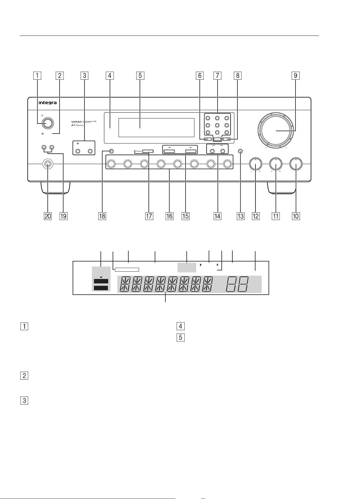
Front panel description
This section identifies and explains the controls and displays on the front panel of the DTM-5.3.
Front panel
AM Phono CDDVD
1 ABC 2 DEF 3 GHI
5 MNO 6 PQR
4 JKL
7 STU 8 VWX 9 YZ
Direct Tuning 0/10/Scan
Clear
Memory
FM Mode
Standby/On
Standby
Speakers
A
Phones
B
Zone 2 Off
Display
Video
Direct Tuning
Tape 2
Tape 1
Monitor
FM
Master Volume
-
Character
Bass
Treble Balance
L
DTM-5.3
R
Display
AB C D E GFHI
STEREO
MODE
AUTO
MONO
Standby/On button
Press this button to turn on the power to the DTM-5.3. The
display indicators light up. Press the button again to set the
unit in Standby mode, in which the display indicators turn off
and no control on the unit is available.
If the main room device is in Standby mode, you can adjust
the zone 2 room.
Standby indicator
This indicator lights up in Standby mode and when the unit
receives a signal from the remote controller.
Zone 2 button and indicator, Off button
This button enables you to enjoy music in another room
(Zone 2). When you press the Zone 2 button, the currentlyselected playback source for Zone 2 appears on the display. If
“Z2 SRC” appears, the source for Zone 2 is the same as the
currently-selected playback source. To change the source for
Zone 2, press the Zone 2 button, then press an input selector
button within five seconds. The Zone 2 indicator lights up. To
select “Z2 SRC” for Zone 2, press the Zone 2 button twice.
To turn off the Zone 2 output, press the Off button. The Zone
2 indicator turns off.
SPEAKERS A B
T-2 MONITOR
AUDIO MUTE FM MUTE TUNED MEMORY
ON OFF
STEREO
kHz
MHz
J
Remote control sensor
Display
A. STEREO MODE, AUTO, MONO indicator
Pressing the FM Mode button each time toggles between
AUTO and MONO indicators.
B. T-2 MONITOR indicator
This indicator lights up when you press the Tape 2 Monitor button, which enables you to monitor the audio signal
during recording to a three-head cassette tape deck connected to the TAPE 2 jack.
C. SPEAKERS A B indicator
This indicates which speaker system you are currently
using.
D. AUDIO MUTE indicator
This indicator flashes while you are using the Mute function.
E. FM MUTE ON OFF indicator
Pressing the FM Mode button each time toggles between
ON and OFF.
SLEEP
CH MIN
6
Page 7

Front panel description
F. TUNED indicator
This indicator lights up when the unit receives a radio station signal
G. STEREO indicator
The indicator lights up when the unit receives an FM stereo radio station signal.
H. MEMORY indicator
The indicator lights up when you press the Memory button to program a radio station.
I. SLEEP indicator
This indicator lights up while the Sleep function is active.
J. Multi function display indicator
This display indicates the input source, frequency, preset
number, and preset name.
Direct T uning button
Use this button to set the frequency. After pressing this button, use the number buttons to input the frequency.
Number (1–9, 0/10) buttons
Use these buttons to program preset channels or select radio
stations.
Alphabetic letters/symbols buttons
Use these buttons to name the preset channels using characters.
Scan button
Press this button to scan the preset channels.
Master V olume dial
This dial adjusts the volume level.
Balance dial
In general, set this dial to the center (12 o’clock) position.
Adjust the dial accordingly if the left and right volume levels
are not balanced, depending on the speaker position or listening position. Turn the dial clockwise to pan the stereo position to the right, and turn it counterclockwise to pan to the
left.
Treble dial
This dial adjusts the high range of the left and right speakers.
Turning the dial to the right from the center position will
emphasize the high range, and turning it to the left will attenuate the high range.
Bass dial
This dial adjusts the low range of the left and right speakers.
Turning the dial to the right from the center position will
emphasize the low range, and turning it to the left will attenuate the low range.
Memory, FM Mode buttons
Memory
Memory button enables you to program or erase preset FM/
AM stations.
FM Mode
Use FM Mode button to set Stereo Mode to Mono if the FM
stereo radio signal being received is frequently interrupted or
contains lots of noise. Pressing the button each time will toggle between AUTO and MONO for STEREO MODE.
Clear
To erase the programmed stations, hold down the Memory
button, then press the FM MODE button.
T uning buttons
Use these buttons to change the tuner frequency. The tuner
frequency is displayed in the front display. It can be changed
in 100 kHz increments for FM and 10 kHz increments for
AM.
When FM is selected, you can hold down one of the tuning
buttons and then release it to activate the auto-search feature.
It will search for a station in the direction of the button you
pressed and stop when it tunes one in.
Input selector buttons
These buttons enable you to select input sources.
To select input sources for the Zone 2 device, first press the
Zone 2 button, then press an Input selector button.
Direct button and indicator
This button enables the function that makes the input source
sound much closer to the original sound source. When you
press this button, the indicator lights up, and the input source
signal bypasses the Bass and Treble control circuits. In this
way, the audio sounds more real and true to the original
source.
To cancel this function, press this button again.
Display button
This button switches the display indication between the frequency value and the channel name if the FM and AM preset
channels have been named.
Speakers A, B buttons
These buttons turn speaker systems A and B On and Off.
Phones
Connect a stereo headphone set to this standard stereo jack.
Audio signals to the left and right speakers will be output to
the headphones.
Character button
Press this button to name the radio stations programmed in
the preset memory using characters.
7
Page 8
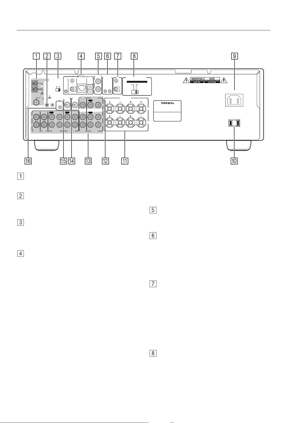
Rear panel description
This section identifies and explains how to use the terminals found on the rear of the DTM-5.3. Before connecting your audio and video components, be sure to read this section carefully and then proceed to the explanations on how to connect each individual component (see page 10).
12 V
ZONE 2
OUT
E
R
TRIGG
IR
OUT
A
SPEAKER IMPEDANCE
IN
SET BEFORE POWER ON
A OR B
8 OHMS MIN.
/SPEAKER
SPEAKERS
SELECTOR
:
B
A OR B : 4 OHMS MIN.
/SPEAKER
A + B : 8 OHMS MIN.
/SPEAKER
L
R
AV RECEIVER
MODEL NO. DTM
RATING:
V 60 Hz
AC 120
AC INLET
-
5.3
A
2.8
AC OUTLET
AC 120 V 60 Hz SWITCHED
120
W 1 A
MAX.
L
R
IN
PHONO
ANTENNA
AM
FM
75
IN
CD
GND
A-BUS
OUTOUT
TAPE 1
ZONE 2
CONTROL
SELECTOR
REMOTE
CONTROL
IN
IR OUT
56K
IR
SUBWOOFER
PRE OUT
OUT
IR OUT 40K
B
A
TAPE 2
MONITOR
OUT
IN
ZONE 2
OUT
DVD
DVD
DC IN
ZONE 2
L
24V 1A
IN
IN
OUT
IN
R
VIDEO
OUT
IN
V
IN
OUT
L
R
VIDEO
ANTENNA
These connectors enable you to connect the FM indoor
antenna and AM loop antenna supplied with the DTM-5.3.
GND
Use this GND terminal to connect the ground (or earth) wire if
a turntable is connected. Refer to “Connecting components”
on page 10.
ZONE 2 CONTROL SELECTOR
This switch enables you to select whether the Zone 2 function
is controlled from the A-BUS system or from the IR system.
Sliding the switch to the left will select A-BUS system control, and sliding it to the right will select IR system control.
A-BUS READY
A-BUS is a simple, efficient, elegant audio distribution system. The wiring installation time is significantly reduced as
only a single CAT-5 wire is run to each location. A-BUS is
easy to use, reliable, affordable, and most of all, far better
sounding than conventional auto former based volume controls.
ZONE 2 OUT: Use a CAT-5 (eight conductor twisted) cable
to connect directly from the receiver’s A-BUS RJ45 Hub to
an A-BUS k e ypad. A-BUS outputs enable connection of up to
four A-BUS keypads.
War ning:
DO NOT connect ZONE 2 OUT to any computer or network
connections (i.e., Ethernet). It will damage the computer or
network components since 24-volt power runs on this cable to
power the amplifier stages of the amplifier module.
IR OUT: Another feature of the A-BUS system is the ability
to control source equipment in a room other than where the
A-BUS module is installed. If you wish to control another
source from the receiver at the A-BUS keypad by remote control, connect the A-BUS or another brand IR emitter on the
receiver’ s 40 K terminal. Then place the emitter on the remote
receiver on the front panel.
Typically, the emitter will work when you connect with a
40 K connector. If it does not work, try a 56 K connector.
DC INPUT: Connect the A-BUS power supply. Do not use
any other AC Adapter on this connector as it may cause
severe damage to the receiver.
Note:
Don’t insert an A-B US connector while Zone 2 or DTM5.3 is on.
ZONE 2 OUT
Connect the device that will be used in the remote zone (Zone
2). For more information on making the connections, refer to
“Connecting the remote zone (Zone 2)” on page 14.
12V TRIGGER ZONE 2 OUT, IN terminal
These terminals are provided so that you can use the DTM-
5.3 to control another externally-connected device. Connect
the component to this 1/8-inch mini-jack terminal. When the
set input source is selected, the device will turn on. Set the
12V TRIGGER terminal using the Zone 2 mode.
When the DTM-5.3 is in Zone 2 mode, this terminal outputs
at 12 V/100 mA.
IR IN/OUT
If the DTM-5.3 is located inside a rack or cabinet that will not
allow infrared beams to reach the IR sensor, you will need to
connect a remote sensor to IR IN input to be able to use the
remote controller.
Then install the remote sensor in an unblocked location at
which you can easily point the remote controller.
Using a mini-jack connector, connect the IR emitter to the IR
OUT terminal on the DTM-5.3 and then place the IR emitter
on the remote sensor of the component or facing it.
Refer to “Operating components not reached by the remote
controller signals (IR IN/OUT)” on page 15.
SPEAKER IMPEDANCE SELECTOR
The DTM-5.3 provides two speaker system connections
(SPEAKER A and SPEAKER B). Set the SPEAKER
IMPEDANCE SELECTOR according to the impedance of
speakers to be connected.
Warning:
Do not plug in the power cord during speaker system connection
and operation of the SPEAKER IMPEDANCE SELECTOR.
8
Page 9
Rear panel description
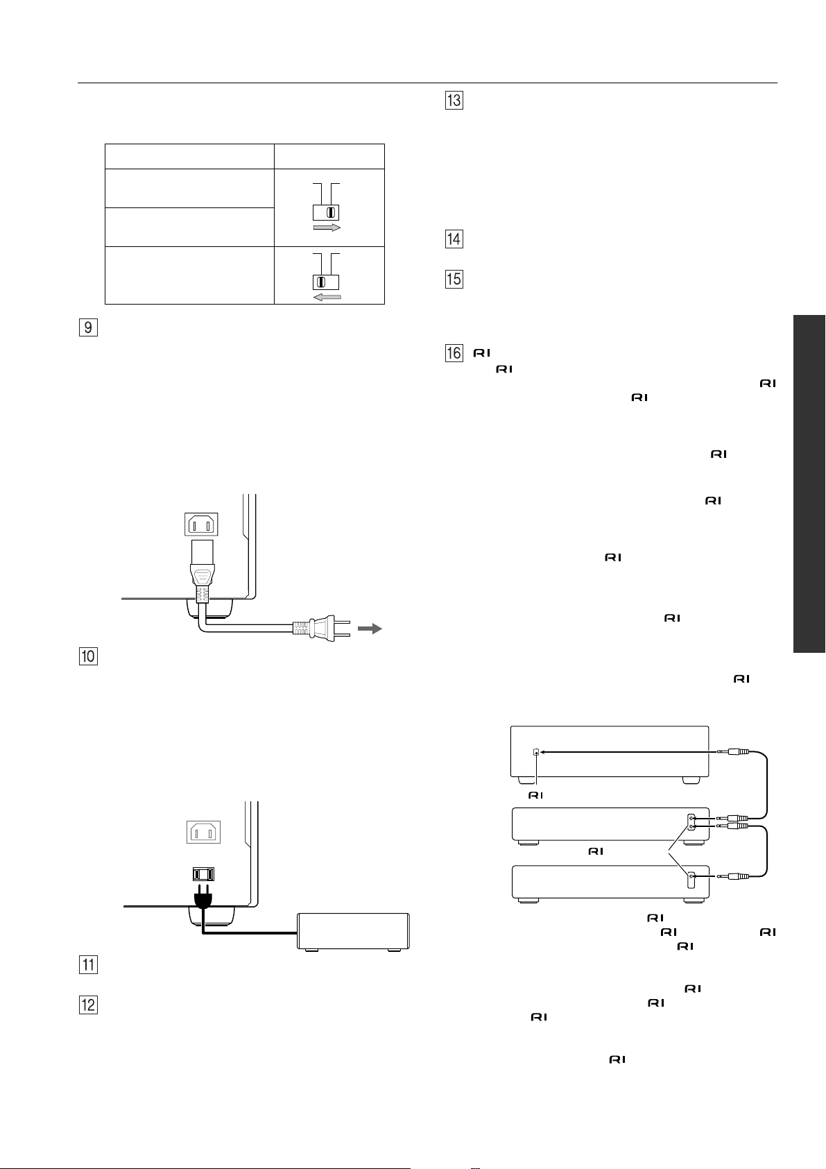
Depending on the impedance of the speakers used, set the
SPEAKER IMPEDANCE SELECTOR on the rear panel as
shown in the table.
Usable speaker impedance Selector position
A or B speaker
4 ohms or higher/speaker
A and B speakers
8 ohms or higher/speaker
A or B speaker
8 ohms or higher/speaker
AC INLET
Plug the supplied power cord into this AC INLET and then
into the power outlet on the wall.
• Do not use a power cord other than the one supplied with the
DTM-5.3. The power cord supplied is designed for use with
the DTM-5.3 and should not be used with any other device.
• Never disconnect the power cord from the DTM-5.3 while
the other end is plugged into a wall outlet. Doing so may
cause an electric shock. Always connect by plugging into
the wall outlet last and disconnect by unplugging from the
wall outlet first.
AC INLET
Power cord
(supplied)
To an AC wall outlet
AC OUTLET
The DTM-5.3 is supplied with AC mains outlet for connecting the power cords from other devices so that their power is
supplied through the DTM-5.3. By doing this, you can use the
Standby/On button on the DTM-5.3 to turn on and off the
connected devices as well.
Caution:
Make sure that the capacity of the other components connected to this unit does not exceed the 120 watts.
AC INLET
AUDIO IN/OUT
There are 6 audio inputs and 3 audio outputs for use with analog signals. The audio inputs and outputs require RCA type
connectors.
• When connecting a VCR or other video component, make
sure you connect the audio and video leads together (i.e.,
both to VIDEO).
• The PHONO jacks are designed for use with turntables that
use moving magnet cartridges.
MONITOR OUT
This output enables you to connect to a television monitor.
SUB WOOFER PRE OUT
This terminal enables you to connect to an active subwoofer.
Note: The subwoofer can only operate when speaker system
A is turned on.
REMOTE CONTROL
The terminal on the DTM-5.3 enables you to connect to
other Integra/Onkyo components equipped with the same
terminal. When a component is -connected, you can point
the remote controller supplied with the DTM-5.3 at the sensor
on the DTM-5.3 and operate that component without having
to switch remote controllers.
In addition, by connecting components to the terminal,
you can also perform the system operations given below.
Power on/ready function
When the DTM-5.3 is in Standby mode, if an -connected
component is turned on, then the DTM-5.3 also turns on and
the input source selected at the DTM-5.3 automatically
switches to that component.
If the power cord for an -connected component is connected to the AC OUTLET on the DTM-5.3, or if the DTM-
5.3 is turned on, this function will not work.
Direct change function
When the play button is pressed on an -connected component, the input source selected at the DTM-5.3 automatically
changes to that component.
Power off function
When the DTM-5.3 is placed in Standby mode, all -connected components are also automatically placed in Standby
mode.
DTM-5.3
REMOTE
CONTROL
connector
Ex: Integra/Onkyo CD player
AC OUTLET
AC 120 V 60 Hz SWITCHED
120 W 1 A
MAX.
Other component
SPEAKERS terminals
Connect the left and right speakers here.
VIDEO IN/OUT
The DTM-5.3 provides two video inputs and one video output. Connect a DVD player, VCR, or other video player to the
input and connect a VCR or other video recorder to the output.
connector
Ex: Onkyo cassette tape deck
To connect components using the terminal, simply connect a remote control cable from this terminal to the
terminal of the other component. An remote control
cable with a 1/8-inch (3.5mm) miniature two-conductor plug
comes with every cassette tape deck, compact disc player,
MD recorder, and DVD player that has an terminal.
• When performing operations with -connected components
using the system, do not use the remote zone (Zone 2).
• For remote control operation, the audio connection cables
must also be connected.
• If a component has two terminals, you can use either
one to connect to the DTM-5.3. The other one can be used
to daisy chain to another component.
9
Page 10
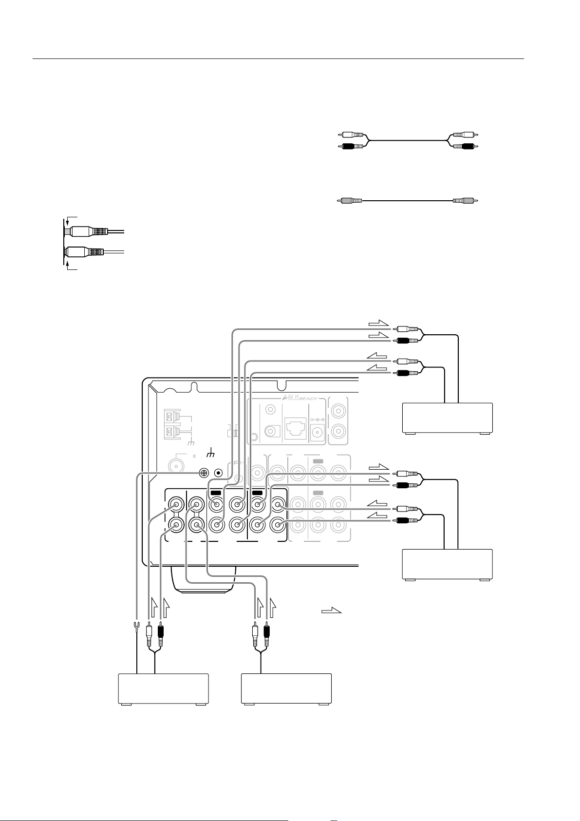
Connecting components
This section explains how to connect the main components to the
DTM-5.3 in the standard manner.
• Be sure to always refer to the instruction manual that came with
the component that you are connecting.
• Do not plug in the power cord until all connections have been
made.
• For input jacks, red connectors (marked R) are used for the right
channel, white connectors (marked L) are used for the left channel, and yellow connectors (marked VIDEO) are used for video
connection.
• Insert all plugs and connectors securely. Improper connections
can result in noise, poor performance, or damage to the equipment.
Improper connection
Inserted completely
Example of audio equipment connection
• Do not bind audio connection cables with power cords and
speaker cables. Doing so may adversely effect the sound quality.
Audio connection cable
L (Left) L
R (Right) R
Video connection cable
Ground
L
R
PHONO
OUT
IN
ANTENNA
AM
FM
75
IN
CD
GND
CONTROL
SELECTOR
A-BUS
OUTOUT
TAPE 1
ZONE 2
REMOTE
CONTROL
IN
B
IR OUT
56K
IR
A
SUBWOOFER
PRE OUT
OUT
TAPE 2
IR OUT 40K
MONITOR
OUT
IN
OUT
ZONE 2
OUT
DVD
IN
IN
DVD
DC IN
24V 1A
OUT
OUT
ZONE 2
L
R
VIDEO
VIDEO
OUT
IN
V
IN
L
R
: signal flow
INOUT
Tape Deck
(TAPE 1)
INOUT
Tape Deck
(TAPE 2)
10
Turntable
(PHONO)
CD Player
(CD)
Page 11

Connecting components
Example of video equipment connections
AUDIO OUTPUT
DVD Player
(DVD)
ANTENNA
AM
FM
75
IN
L
VIDEO OUTPUT
ZONE 2
CONTROL
SELECTOR
A-BUS
GND
REMOTE
CONTROL
IN
OUT
IR OUT
56K
IR
SUBWOOFER
PRE OUT
IN
A
OUT
IR OUT 40K
B
MONITOR
OUT
IN
ZONE 2
OUT
DVD
Monitor TV
VIDEO IN
Video Cassette Recorder
(VIDEO)
ZONE 2
DC IN
24V 1A
OUT
L
VIDEO IN
VIDEO OUT
R
VIDEO
OUT
IN
IN
V
OUT
IN
IN
L
AUDIO OUT
AUDIO IN
R
PHONO
CD
TAPE 1
TAPE 2
DVD
R
VIDEO
If there should be interference between the TV and this unit, place this unit as far from the TV as possible.
We do not recommend the use of a common TV/FM antenna. (Refer to “Connecting antennas” on page 13.)
11
Page 12

Connecting speakers
Connecting the speaker
You can connect two separate pairs of speaker systems.
Please connect each speaker according to the illustration, observing
the correct connections for R, L, + and –.
Check the speaker impedance, then set the SPEAKER IMPEDANCE
SELECTOR switch accordingly. Refer to pages 8 and 9 for details.
Notes:
• Do not use unnecessarily long or extremely thin speaker leads.
If the DC resistance of the speaker leads is too high, the damping factor will decrease, adversely affecting the sound quality.
• When you are using only one speaker or when you wish to listen to monaural (mono) sound, a single speaker should never be
connected in parallel to both the right and left-channel terminals
simultaneously.
SPEAKERS
B
L
R
• To prevent damage to circuitry, never
short-circuit the positive (+) and negative (–) speaker wire.
• Be sure to connect the positive and negative cables for the speakers properly. If
they are connected to the wrong terminal,
the left and right signals will be reversed
and the audio will sound unnatural.
• Do not connect more than one speaker
cable to one speaker terminal. Doing so
may damage the DTM-5.3.
SPEAKERS
Subwoofer
B
L
R
NO
Connecting the speaker cable
1. Strip away 5/8 inch (15 mm) of wire insulation.
2. Twist wire ends very tight.
3. Unscrew.
4. Insert wire.
5. Screw.
5/8 inch
(15 mm)
1
2
34 5
Connecting a subwoofer
Use the SUBWOOFER PRE OUT jack to connect a subwoofer
with a built-in power amplifier. If your subwoofer does not have a
built-in amplifier, connect an amplifier to the PRE OUT SUBWOOFER jack and the subwoofer to the amplifier.
Note:
The SUBWOOFER PRE OUT can only operate when speaker system A is turned on.
SPEAKER A
Right ch.
Left ch.
12
L
R
IN
PHONO
ANTENNA
AM
FM
75
IN
CD
GND
CONTROL
SELECTOR
A-BUS
OUT
TAPE 1
ZONE 2
REMOTE
CONTROL
IN
IR OUT 40K
B
IR OUT
56K
IR
A
SUBWOOFER
PRE OUT
OUT
TAPE 2
MONITOR
OUT
IN
ZONE 2
OUT
DVD
IN
IN
DVD
DC IN
24V 1A
OUT
OUT
L
R
VIDEO
VIDEO
ZONE 2
OUT
IN
IN
TRIGG
ZONE 2
OUT
V
L
R
12 V
E
R
IN
A
Right ch.
IR
IN
OUT
SPEAKERS
8 OHMS MIN.
/SPEAKER
SPEAKER IMPEDANCE
SELECTOR
SET BEFORE POWER ON
:
A OR B
A OR B : 4 OHMS MIN.
/SPEAKER
A + B : 8 OHMS MIN.
/SPEAKER
B
SPEAKER B
L
R
Left ch.
Page 13

Connecting antennas
To use the tuner of the DTM-5.3, it is necessary to prepare the supplied FM and AM antennas.
• Adjustment and placement of the FM and AM antennas for better reception is best performed while listening to a station broadcast.
• If better reception cannot be obtained, then placement of an outside antenna is recommended.
Assembling the AM loop antenna
Assemble the loop antenna as shown in the illustration.
• Refer to “Connecting the AM loop antenna” below for details
on connecting the loop antenna.
Insert into the hole.
Connecting the AM antenna cable
1. Push the lever.
2. Insert the wire into the hole.
3. Release the lever.
12
3
Connecting the included antennas
Connecting the FM indoor antenna:
The FM indoor antenna is for indoor use only. During use, extend
the antenna and move it in various directions until the clearest signal is received. Fix it with push pins or similar implements in the
position that will cause the least amount of distortion.
If the reception is not very clear with the attached FM indoor
antenna, the use of an outdoor antenna is recommended.
Connecting the AM loop antenna:
The AM loop antenna is for indoor use only. Set it in the direction
and position in which you receive the clearest sound. Locate it as
far away as possible from the DTM-5.3, televisions, speaker
cables, and power cords.
When reception is not satisfactory with the attached AM loop
antenna alone, connection of an outdoor antenna is recommended.
Connecting an FM outdoor antenna
Please make sure that you follow these guidelines:
• Keep the antenna away from noise sources (neon signs, busy
roads, etc.).
• It is dangerous to locate the antenna close to power lines. Keep
it well away from power lines, transformers, etc.
• To avoid the risk of lightning and electrical shock, grounding is
necessary. Follow item 14 of the “Important Safeguards” on
page 2 when you install the outdoor antenna.
ANTENNA
AM
FM
75
Connecting an AM outdoor antenna
An outdoor antenna will be more effective if it is stretched horizontally above a window or outside.
• Do not remove the AM loop antenna.
• To avoid the risk of lightning and electrical shock, grounding is
necessary. Follow item 14 of the “Important Safeguards” on
page 2 when you install the outdoor antenna.
Outdoor
antenna
(indoor)
AM loop
antenna
ANTENNA
AM
FM
75
FM antenna
ANTENNA
AM
(indoor)
AM loop
FM
75
Strip away the insulation from the
end of the cable, then fully insert
the stripped end of the cable.
antenna
Hint:
Either of the split ends of the AM antenna can be connected to
either terminal. Unlike speaker cabling, there is no polarity for AM
broadcast signals.
Directional linkage
Do not use the same antenna for both FM and TV (or VCR) reception since the FM and TV (or VCR) signals can interfere with each
other. If you must use a common FM/TV (or VCR) antenna, use a
directional linkage type splitter.
Directional linkage
type splitter
To DTM-5.3 To TV (or VCR)
13
Page 14

Connecting the remote zone (Zone 2)
The DTM-5.3 allows you to connect an additional set of speakers and place them in a different room or an area separated for listening to
music. This other room or area is referred to as the remote zone (Zone 2), while the room in which the DTM-5.3 is referred to as the main
zone. In addition, the IR IN/OUT allows you to control the DTM-5.3 from the remote zone (Zone 2) using the remote controller, even though
the remote zone may be physically separated. The diagram illustrates the proper connections for the remote zone.
Zone 2 connections
The ZONE 2 OUT terminal provides constant output. Connect to
the LINE input of the amplifier (CD, tape, etc.). Adjust the volume
with the amplifier connected to the ZONE 2 OUT terminal.
1 Connect the DTM-5.3 to the amplifier for the remote
zone.
2 Connect the remote zone speaker cables to the speaker
terminals on the amplifier.
Adjust the volume level at the amplifier.
Zone 2 Left speaker Zone 2 Right speaker
Zone 2 amplifier
ZONE 2
OUT
L
Zone 2 Control Selector
When you use the A-BUS system, switch the ZONE 2 CONTROL
SELECTOR to A-BUS (left side). When you use an IR controller,
switch the Zone 2 CONTROL SELECTOR to IR (right side).
A-BUS
IR
A-BUS
IR
Left (white)
Right (red)
R
DTM-5.3
14
Page 15

Operating components not reached by the
remote controller signals (IR IN/OUT)
The following equipment (sold separately) is essential for operation:
• Onkyo’s Multi-Room System kits (IR Remote Controller Extension System), or
• Multiroom A/V distribution and control systems from Niles
®
and Xantech® to name a few.
Controlling the DTM-5.3 in the main room from
a remote zone (Zone 2)
The IR IN input allows you to control the DTM-5.3 from a remote
zone (Zone 2) using the remote controller, even though the remote
zone may be physically separated. The diagram below illustrates
how to make the proper connections for the remote zone.
IR IN
IR Receiver
DTM-5.3
Connecting
block
Remote controller
Main room
: Signal flow
Make connection as shown below. Do not plug the equipment into
the power source until the connection is completed.
from connecting block
Zone 2 room
Controlling another component in the main room
via the DTM-5.3 from a remote zone (Zone 2)
In this situation, you will need to use a commercially-available IR
emitter. Connect the mini plug of the IR emitter to the IR OUT terminal on the DTM-5.3. Then place the IR emitter on the remote
sensor of the component or facing it. When the IR emitter is connected, only the signal input to the IR IN terminal is output to the
IR OUT terminal. The signal input from the remote sensor on the
front of the DTM-5.3 will not be output to the IR OUT terminal.
IR OUT
other
component
IR IN
DTM-5.3
IR Emitter
Connecting
block
Main room
IR Receiver
Remote controller
Zone 2 room
: Signal flow
Mini plug cable
IR
OUT
IN
DTM-5.3
IR
IN
OUT
DTM-5.3
: Signal flow
Mini plug
other component
IR Emitter
Remote control
sensor
Emitter
Mini plug cable
15
Page 16

Connecting the power
• Before plugging in the unit, confirm that all connections have been made properly.
• Before turning on the power, be sure that the VOLUME knob is fully turned counterclockwise.
• Turning on this unit’s power may cause a momentary power sur ge, which might interfere with other electrical equipment, such as computers. If so, connect the unit to a wall outlet on a different circuit.
Plug the power cord into the AC INLET, then plugging the power
cord plug into an AC outlet puts the unit in Standby mode (the
Standby indicator is lit).
Pressing the Standby/On button turns on the unit and lights up the
display. If this switch is pressed again, the unit returns to Standby
mode.
Standby indicator
Standby/On button
Standby/On
Standby
Speakers
B
A
Zone 2 Off
Phones
Direct Tuning
Display
Tape 2
Video
Tape 1FMAM Phono CDDVD
Monitor
1 ABC 2 DEF 3 GHI
5 MNO 6 PQR
4 JKL
7 STU 8 VWX 9 YZ
Direct Tuning 0/10/Scan
Clear
Memory
FM Mode
Master Volume
-
Character
Bass
Treble Balance
R
L
DTM-5.3
To wall outlet
On the remote controller, press the On button to turn on the power
to the DTM-5.3, then press the Standby button to place the unit in
Standby mode.
On button
Standby button
16
Page 17

Installing the remote controller batteries
Installing the batteries
1 Open the battery compartment cover by pushing the tab
and opening the cover.
2 Insert two AA (R6 or UM-3) batteries into the battery
compartment. Carefully follow the polarity diagram (positive (+) and negative (–) symbols) inside the battery
compartment.
3 After batteries are installed and seated correctly, replace
the compartment cover.
Notes:
• Do not mix new batteries with old batteries or different kinds of
batteries.
• To avoid corrosion, remove the batteries if the remote controller
is not to be used for a long time.
• Remove dead batteries immediately to avoid damage from corrosion. If the remote controller does not operate smoothly,
replace both the batteries at the same time.
Remote controller operation
Point the remote controller toward the remote control sensor. The
Standby indicator lights up when the unit receives a signal from the
remote controller.
Remote control sensor
Standby indicator
30˚
30˚
DTM-5.3
approx. 5 m
(16 feet)
Notes:
• Place the unit away from strong light such as direct sunlight or
inverted fluorescent light, which can pre v ent proper operation of
the remote controller.
• Using another remote controller of the same type in the same
room or using the unit near equipment that uses infrared rays
may cause operational interference.
• Do not put objects on the remote controller. Its buttons may be
pressed by mistake and drain the batteries.
• Make sure the audio rack doors do not have colored glass.
Placing the unit behind such doors may prevent proper remote
controller operation.
• If there is any obstacle between the remote controller and the
remote control sensor, the remote controller will not operate.
17
Page 18
Setup and operation
Basic operations
Master Volume
5 MNO 6 PQR
-
Clear
Memory
Character
FM Mode
Standby/On
Standby
Speakers
A
Phones
Direct
1 ABC 2 DEF 3 GHI
4 JKL
7 STU 8 VWX 9 YZ
B
Zone 2 Off
Display
Video
Direct Tuning
Tape 2
Tape 1
Monitor
Direct Tuning 0/10/Scan
FM
AM Phono CDDVD
Input selector buttonsSpeakers A/B
Phono
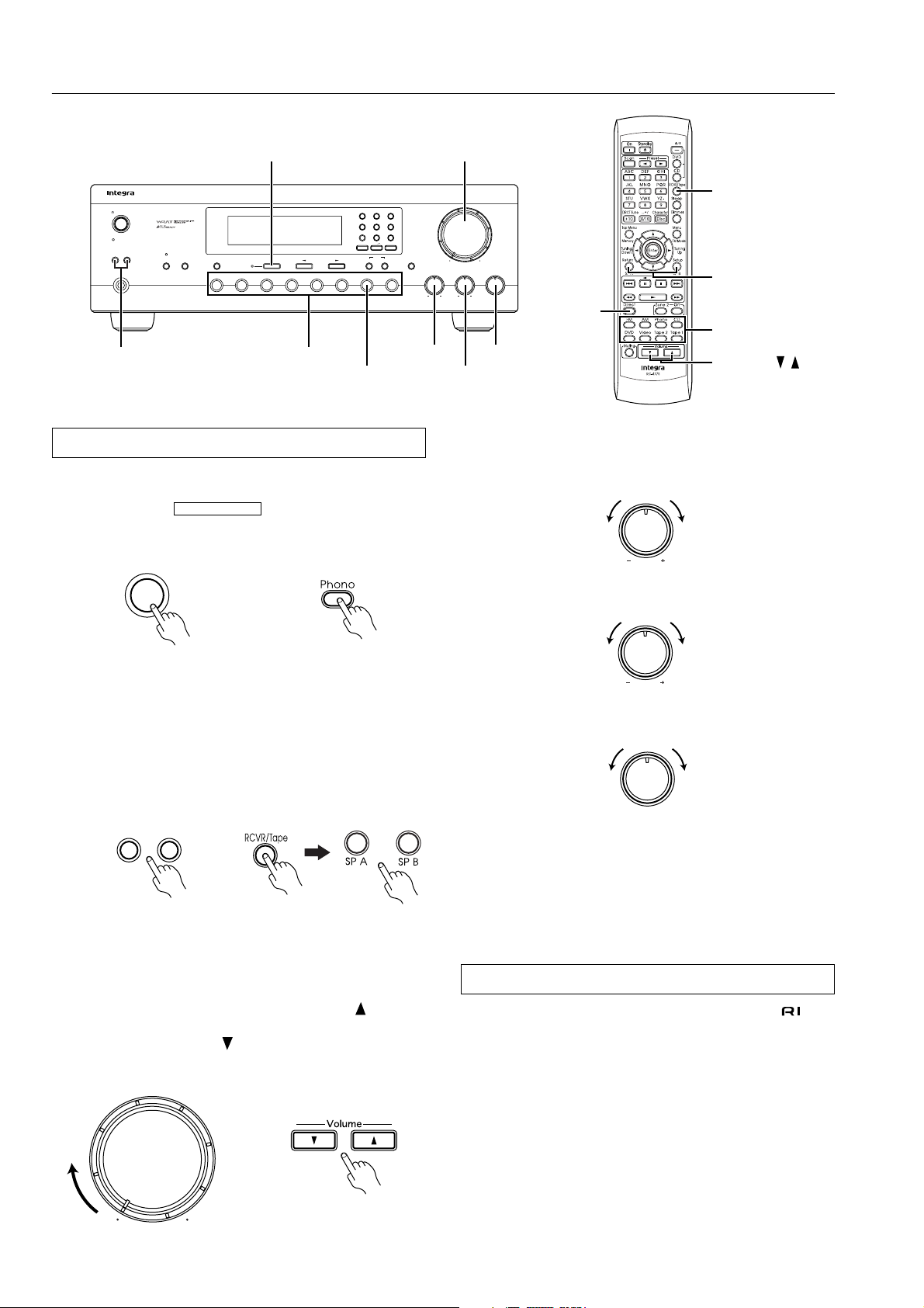
Listening to your favorite source
1 Select the source you wish to listen to using the input
selector (e.g., PHONO).
Confirm that the indicator is not lit when a
source other than Tape 2 Monitor is selected. Also check that
the AUDIO MUTE indicator is not lit.
Phono
T-2 MONITOR
Remote controller
Master Volume
Bass
Treble Balance
R
L
Bass
DTM-5.3
Balance
Direct
Treble
5 Adjust to your desired tone.
Bass: Turn clockwise to boost or counterclockwise to attenuate
the bass.
Treble: Turn clockwise to boost or counterclockwise to attenuate the treble.
RCVR/Tape
SP A / SP B
Input selector
Volume ( / )
Bass
Treble
2 Select the speakers.
Press the button for the speakers to which you wish to listen
(Speakers A and/or B). For the remote controller, press the
RCVR/Tape mode button before pressing the SP A or SP B button.
The corresponding A and/or B indicator lights up on the display
panel. You will hear from the speakers any sounds passing
through the unit. If both Speakers (A and B) are set to OFF, the
speakers will emit no sound.
Speakers
A
B
Remote controller
3 Start playing the selected input source.
Follow the operating instructions for the selected unit.
If you select FM or AM, refer to “Receiving stations” on
page 20.
4 Adjust the level.
Turn the Master Volume knob clockwise or press the button on
the remote controller to increase the volume level. Turn the knob
counterclockwise or press the button on the remote controller to
decrease the volume level.
Master Volume
Remote controller
6 The Balance knob controls the relative volume level of
the left and right speakers or headphones.
Balance
R
L
Notes:
• The power does not shut off completely when you turn off the
power. The power cord should be removed from the AC wall
outlet when not in use for a prolonged period of time.
• You cannot adjust the bass and treble when the Direct button is
turned on.
Direct change function
When a compact disc player and tape deck that feature jacks
are connected together, you can use the direct change function.
When you operate the compact disc player or tape deck, the input
selector on the DTM-5.3 switches automatically to the desired
component.
It is not necessary to switch the DTM-5.3’s input selector when
you change listening sources.
Note:
This direct change function does not work when Zone 2 is being
controlled.
18
Page 19

Basic operations
Listening using the headphones
You can connect stereo headphones with a standard binaural (stereo) plug to the Phones jack.
When the headphone plug is inserted, the speakers are not automatically muted but can be controlled using the Speakers A/B buttons.
Speakers
B
A
Phones
Mute function (Remote controller only)
To temporarily switch off the sound from the speakers or headphones, press the Muting button on the remote controller.
The AUDIO MUTE indicator will flash.
Sleep function (Remote controller only)
The sleep timer can power off the system after a specified time
period.
To operate this function, use the remote control supplied with your
DTM-5.3.
1 Start playing the source you would like to listen to CD, tape
or radio broadcast.
2 Set the amount of time after which you want the system to
turn off.
The sleep timer works for up to 90 minutes. You can shorten the
timer by 10 minute increments by pressing the Sleep button until
the desired time has been reached.
After the set time passes, the power switches off automatically.
Sleep
Muting
The muting function will be cancelled if you:
• press the Muting button again, or
• turn the power off, then on again.
AUDIO MUTE
SLEEP
MIN
90 80 70
Cancel 10 20
The timer will be cancelled if you:
• press the Sleep button until it changes to the display of the
source to which you are listening, or
• turn off the power while the timer is operating.
19
Page 20

Receiving stations
Please make sure that the and AUDIO MUTE indicators are not lit.
T-2 MONITOR
For the remote controller, press the RCVR/Tape mode button before performing the
procedure in this section.
Tuning
Number buttons
Standby/On
Standby
Speakers
A
Phones
1 ABC 2 DEF 3 GHI
5 MNO 6 PQR
4 JKL
-
7 STU 8 VWX 9 YZ
B
Zone 2 Off
Display
Video
Direct Tuning
Tape 2
Tape 1
Monitor
Direct Tuning 0/10/Scan
Clear
Character
Memory
FM Mode
FM
AM Phono CDDVD
Master Volume
Bass
Treble Balance
R
L
DTM-5.3
AM Direct TuningFM
Tuning the radio (Manual tuning)
When the frequency is not known (Manual tuning)
1 Press the FM or AM button.
FM
AM
or
Tuning the radio (Direct tuning)
When the frequency is known (Direct tuning)
1 Press the FM or AM button.
FM
DRCT
Tuning
Down
AM
Number
buttons
RCVR/Tape
Tune
Tuning
Up
AMFM
or
2 Use the
Tuning buttons (or Tuning Down and Up
buttons on the remote controller) to change the frequency.
(Up).....the frequency increases.
(Down).....the frequency decreases.
FM MUTE TUNED
STEREO
ON
Tuning
MHz
TUNED
kHz
• The frequency is changed in 100 kHz steps in FM and
10 kHz in AM each time a tuning selector button is pressed.
• If a button is held continuously for more than 0.5 seconds,
the frequencies are scanned automatically (FM auto tuning
mode). When a broadcast is received, scanning stops.
2 Press the Direct Tuning button (or DRCT Tune button on
the remote controller).
The “-- --” will flash for 16 seconds in the frequency display.
FM MUTE TUNED
STEREO
Direct Tuning
CH
3 Enter the frequency by pressing the number buttons
ON
MHz
CH
while the cursors are flashing.
1 ABC 2 DEF 3 GHI
CH
5 MNO 6 PQR
4 JKL
7 STU 8 VWX 9 YZ
/
0/10
-
FM MUTE TUNED
STEREO
ON
FM MUTE TUNED
STEREO
ON
MHz
MHz
CH
CH
Example: 88.1MHz 8 ➔ 8 ➔ 1
• If you enter a frequency that is out of range, the unit will return
to the previous frequency. If this happens, repeat the procedure.
20
Page 21

Receiving stations
STEREO
MODE
FM MUTE TUNED
ON
STEREO
AUTAUTO
MONOMONO
MHz
CH
FM MUTE TUNED MEMORY
ON
STEREO
MHz
CH
Memory
Clear
FM Mode
FM MUTE TUNED
ON
STEREO
MHz
CH
1 ABC 2 DEF 3 GHI
4 JKL
5 MNO 6 PQR
7 STU 8 VWX 9 YZ
-
0/10
/
Number buttons
Standby/On
Standby
Speakers
A
Phones
B
Zone 2 Off
Display
Video
Direct Tuning
Tape 2
Tape 1
Monitor
1 ABC 2 DEF 3 GHI
5 MNO 6 PQR
4 JKL
-
7 STU 8 VWX 9 YZ
Direct Tuning 0/10/Scan
Clear
Memory
Character
FM Mode
FM
AM Phono CDDVD
FM Mode
Memory
Listening to stereo radio stations (FM only)
If you tune in a stereo FM station, the STEREO indicator will be
illuminated if the signal is sufficiently strong.
If the signal is weak, it may be impossible to tune in the desired
station. In this case, tune as follows:
Press the FM Mode button. FM MUTE OFF lights up. At this time,
the station will be received in mono and noise will be heard.
Select the station to which you wish to listen.
Memory
Clear
FM Mode
FM MUTE
OFF
Master Volume
Memory
Bass
Treble Balance
R
L
DTM-5.3
Programming radio stations
A total of 40 stations can be stored in the memory.
1 Select the frequency that you wish to store in memory.
(Refer to “Tuning the radio” on page 20.)
2 Press the Memory button.
The MEMORY indicator will light for 8 seconds.
Number
buttons
RCVR/Tape
FM Mode
If the MONO indicator lights up while a station is tuned in, the station will be received in mono even if it is a stereo station.
You can change the STEREO MODE AUTO/MONO settings by
pressing the FM MODE button.
STEREO
MODE
AUTUTO
MONOMONO
3 Select the desired memory number using the number
buttons.
Press button 0/10 when choosing memory number 10.
E.g.:
1 ABC
5 MNO
15:
2 DEF
20:
0/10
/
21
Page 22

Receiving stations
Standby/On
Standby
Speakers
B
A
Zone 2 Off
Phones
Display
Tape 2
Video
Monitor
Number buttons
Direct Tuning
FM
Tape 1
AM Phono CDDVD
AMFM
1 ABC 2 DEF 3 GHI
5 MNO 6 PQR
4 JKL
7 STU 8 VWX 9 YZ
Direct Tuning 0/10/Scan
Clear
Memory
FM Mode
FM Mode
Memory
Scan
-
Character
Preset ( / )
Scan
Number
buttons
Master Volume
Bass
Treble Balance
R
L
DTM-5.3
RCVR/Tape
AM
FM
Selecting preset stations
First, select the tuner as the source by pressing the AM or FM input
selector button.
Input the memory number you wish to receive by pressing the
number buttons. For the remote controller, press the RCVR/Tape
mode button before pressing the number buttons.
or
Press the Scan button.
When the desired station is located, press the Scan button again and
scanning will stop.
or
Press the Preset
1 ABC 2 DEF 3 GHI
4 JKL
7 STU 8 VWX 9 YZ
or button on the remote controller.
5 MNO 6 PQR
/
0/10
-
Scan
or
or
Cancelling preset stations
1 Select the station that you wish to cancel as explained in
the previous section.
FM MUTE TUNED
STEREO
ON
AUTAUTO
MONOMONO
2 Press the FM Mode button while holding down the Mem-
ory button.
“--” will appear on the display.
Once the preset station has been cancelled, you can use the
memory location to store another station.
Memory
Clear
FM Mode
MEMORY
CH
MHz
CH
CH
22
Page 23

Entering station names
Alphabetic letters/
symbols buttons
1 ABC 2 DEF 3 GHI
5 MNO 6 PQR
4 JKL
7 STU 8 VWX 9 YZ
Direct Tuning 0/10/Scan
Clear
Memory
FM
FM Mode
AM Phono CDDVD
Character
Master Volume
-
Character
Bass
Standby/On
Speakers
A
Tuning
Standby
B
Zone 2 Off
Phones
Direct Tuning
Display
Tape 2
Video
Tape 1
Monitor
Display
Direct Tuning
While receiving a preset FM or AM station, a maximum of eight
characters consisting of letters, numbers and some symbols can be
stored to represent the station name.
Characters which can be entered:
A B C D E F G H I J K L M N O P Q R S T UV W X Y Z
1 2 3 4 5 6 7 8 9 0 –
/
*
Note: indicate a space.
Note: For the remote controller , press the RCVR/Tape mode button
before performing the procedure in this section.
Entering characters
As an example, assume an FM station with a frequency of
89.5 MHz has been stored in preset number 2CH and will be given
the name “ONKYO.”
1 Select the desired station.
(Refer to “Selecting preset stations” on page 22.)
SPEAKERS A
AUTAUTO
MONOMONO
2 Press the Character button.
The frequency disappears from the display and the cursor (_)
flashes.
Character
SPEAKERS A
3 Continue pressing the 5MNO button until “O” is dis-
played.
With each press of the button, the character that appears in the
display changes in the following sequence:
5 ➔ M ➔ N ➔ O ➔ 5 ...
If a button is not pressed within one second, the cursor automatically moves to the next position.
To delete a character, press the Direct Tuning button. After the
selected character is deleted, all characters to the right of the
deleted character move one space to the left.
5 MNO
SPEAKERS A
FM MUTE TUNED
STEREO
ON
FM MUTE TUNED
ON
FM MUTE TUNED
STEREO
ON
STEREO
MHz
CH
CH
CH
Number
buttons
RCVR/Tape
Character
Tuning
Up
Treble Balance
DRCT
Tune
Tuning
Down
R
L
DTM-5.3
5 Press the Character button to store the entered characters.
Character
SPEAKERS A
FM MUTE TUNED
STEREO
ON
If a button is not pressed within 16 seconds, the operation will
end automatically.
• Press the Display button when you wish to check the frequency
while you are entering the characters.
Changing an entered character
1 Select the desired station.
(Refer to “Selecting preset stations” on page 22.)
SPEAKERS A
SPEAKERS A
SPEAKERS A
SPEAKERS A
FM MUTE TUNED
ON
SPEAKERS A
AUTUTO
MONOMONO
2 Press the Character button.
The first character and the cursor flash alternately.
Character
3 Press the Tuning button (or Tuning Down and Up
buttons on the remote controller) to move the cursor to
the character that you wish to change.
The cursor moves to the right when the button is pressed and
to the left when the button is pressed.
Tuning
4 Enter the desired character.
The previous character is replaced with a new character.
-
9 YZ
5 Press the Character button.
Character
CH
STEREO
CH
4 Continue pressing number buttons to enter the desired
characters.
To enter N, press the 5MNO button.
To enter K, press the 4JKL button
To enter Y, press the 9YX- button.
5 MNO
4 JKL
-
9 YZ
5 MNO
SPEAKERS A
Cleaning all characters
1 Select the desired station.
(Refer to “Selecting preset stations” on page 22.)
2 Press the Character button.
3 Hold down the Memory button and press the FM Mode
button.
All characters entered for the selected station are cleared.
4 Press the Character button one more time.
23
Page 24

Recording a source
Standby/On
Standby
Speakers
A
Phones
B
Zone 2 Off
Display
Video
Direct Tuning
Tape 2
Tape 1
Monitor
1 ABC 2 DEF 3 GHI
5 MNO 6 PQR
4 JKL
-
7 STU 8 VWX 9 YZ
Direct Tuning 0/10/Scan
Clear
Memory
Character
FM Mode
FM
AM Phono CDDVD
Input selector buttons
Recording an audio source
Please read the instruction manuals concerning operation of each
unit.
1 Insert a blank tape into the tape deck.
2 Press the button (other than Tape 2 Monitor) for the
source you wish to record.
Video
Tape 2
Monitor
Tape 1DVD
FM
AM Phono CD
• When DVD or Video is selected, the audio portion of the program will be recorded.
• When FM or AM is selected, set the tuner to the station from
which you wish to record.
• When TAPE 1 is selected, it will record to TAPE 2.
• When either DVD, Video, FM, AM, Phono or CD is selected,
you will be able to record to both TAPE 1 and TAPE 2.
3 Put the tape deck in recording mode. Begin playing the
source.
Set the proper recording level using the recording controls on
the tape deck. During recording and dubbing operations, if any
controls (bass, treble etc.) on the unit are changed, the tone will
not change.
Note:
Recording from TAPE 2 to TAPE 1 is not possible.
Master Volume
Bass
Treble Balance
R
L
DTM-5.3
Input selector
Tape-to-Tape dubbing
1 Load the original tape in the TAPE 1 tape deck and a
blank tape in the TAPE 2 tape deck.
2 Press the Tape 1 button.
Tape 1
3 Place the TAPE 1 tape deck in playback mode and the
TAPE 2 tape deck in recording mode.
DTM-5.3
Recording Playback
Tape deck (TAPE 2)
Tape deck (TAPE 1)
(TAPE 1, TAPE 2)
24
DTM-5.3
Recording Playback
Tape deck
Turntable
CD player
VCR, VDP
Page 25

Recording a source
Standby/On
Standby
Speakers
A
Phones
B
Zone 2 Off
Display
Video
Direct Tuning
Tape 2
Tape 1
Monitor
1 ABC 2 DEF 3 GHI
5 MNO 6 PQR
4 JKL
-
7 STU 8 VWX 9 YZ
Direct Tuning 0/10/Scan
Clear
Memory
Character
FM Mode
FM
AM Phono CDDVD
Input selector buttons
Video disc player (or video camcorder) to VCR
recording
Video disc programs can be recorded onto a VCR (VIDEO).
1 Load a disc in the video disc player, and a blank tape in
the VCR (VIDEO).
2 Press the DVD button.
DVD
Master Volume
Bass
Treble Balance
R
L
DTM-5.3
Input selector
Adding new sound to a video tape during video
editing
During video tape editing, you can add sound to the recording VCR
from various audio program sources.
1 Insert the disc or tape from which you wish to record into
the DVD or VCR connected to the DVD connector.
2 Insert a blank video tape in the VCR connected to the
VIDEO connector.
3 Press the DVD button.
DVD
3 Begin playback on the video disc player and begin
recording on the VCR.
DTM-5.3
Recording Playback
VCR (VIDEO)
DVD
4 Select the audio program source (Tape 1, FM, AM,
Phone, CD).
Tape 1
FM
AM Phono CD
5 Begin playback of the video connected to the DVD con-
nector. Start the sound source, then start recording on
the VIDEO.
Refer to the video disc player, video camcorder or VCR instruction
manuals for additional information.
DTM-5.3
Audio
Video
playback
DVD, VCR (DVD)
VCR (VIDEO)
Video
recording
recording
Audio
playback
Turntable
CD player
Tape dack
25
Page 26

Using Tape 2 Monitor
Standby/On
Standby
Speakers
A
Phones
B
Zone 2 Off
Display
Video
Direct Tuning
Tape 2
Tape 1
Monitor
1 ABC 2 DEF 3 GHI
5 MNO 6 PQR
4 JKL
-
7 STU 8 VWX 9 YZ
Direct Tuning 0/10/Scan
Clear
Memory
FM Mode
FM
AM Phono CDDVD
Tape 2 Monitor
Unless the component connected to the TAPE 2 connectors is used,
the indicator in the main unit’s display should not
T-2 MONITOR
be lit; otherwise, the sound from other sources will not be heard.
If a 3-head tape deck is connected to the TAPE 2 connectors, you
can use the Tape 2 Monitor to monitor the recording.
Notes:
• Even when Tape 2 is not selected as the source (the
T-2 MONITOR
to the TAPE 2 output.
• If you select a different input source while listening to the Tape
2 Monitor sound, the indicator flashes for a few
seconds. However, the audio signal does not change.
indicator is not lit), the source signal is still sent
T-2 MONITOR
Master Volume
Character
Bass
Treble Balance
R
L
DTM-5.3
Tape 2
DTM-5.3
T-2 MONITOR
AMP.
T-2 MONITOR
Recording
Tape deck (TAPE 2)
PlaybackPlayback
CD player, etc.
Monitoring during recording
You can monitor the source signal through the speakers or
headphones when Tape 2 Monitor is turned off.
If the indicator in the display is not lit, the sound
T-2 MONITOR
from the source should be audible. If a 3-head tape deck connected
to the TAPE 2 connectors is used for recording, press either the
Tape 2 button on the remote controller or the Tape 2 Monitor button on the main unit. “TAPE 2” will appear in the display for a few
seconds: the indicator will light up and the sound
you just recorded will be audible.
To return to listening to the source sound, press either the Tape 2
button on the remote controller or the Tape 2 Monitor button on the
main unit. The indicator turns off.
Tape 2
Monitor
T-2 MONITOR
T-2 MONITOR
T-2 MONITOR
Remote controller
or
or Graphic Equalizer
Using a graphic equalizer
1 Connect the graphic equalizer to the TAPE 2 connectors on
the rear panel of the DTM-5.3.
2 If a second tape deck is used, connect it to the tape deck con-
nectors on the graphic equalizer.
3 Press the Tape 2 button on the remote controller or the
Tape 2 Monitor button on the main unit.
The indicator on the main unit’s display lights
T-2 MONITOR
up.
4 Follow the operating instructions for the graphic equalizer.
To record an equalized signal, use the tape deck connected to
the equalizer.
Tape 2
Monitor
Remote controller
T-2 MONITOR
or
26
Page 27

Enjoying music in the remote zone
Zone 2 indicator
Preset
/
Standby/On
Standby
Speakers
B
A
Phones
Zone 2
Zone 2 Off
Off
1 ABC 2 DEF 3 GHI
5 MNO 6 PQR
4 JKL
-
7 STU 8 VWX 9 YZ
Direct Tuning 0/10/Scan
Clear
Memory
Character
FM Mode
AM Phono CDDVD
Video
Direct Tuning
Tape 2
Tape 1
Monitor
FM
Display
Master Volume
Bass
Treble Balance
R
L
DTM-5.3
Input selector buttons
On, Standby
Zone 2
Off
Input selector
Zone 2 operation from the main room
To select a source for the zone 2 room other than the source
selected for the main room.
1 Press the Zone 2 button, the Zone 2 indicator flashes.
2 Select an input source within five seconds.
The Zone 2 indicator will light up.
Example: When the CD button is pressed.
AUTAUTO
MONOMONO
If you want to change the source for the zone 2 room to the
same source that is selected for the main room, press the Zone 2
button again until “Z2 SRC” appears in the display.
To select the same source as that of the main room to zone 2
room.
1 Press the Zone 2 button twice while the Zone 2 indicator
is flashing (within 5 seconds).
The Zone 2 indicator will light up continuously.
AUTAUTO
MONOMONO
Zone 2 (A-BUS or IR) operation in the zone 2 room
1 Press the On button on the remote controller.
The power to the Zone 2 devices turned on.
2 Select an input source.
Notes:
• If you select FM or AM, use the Preset / buttons to select a
preset channel.
• Pressing the Standby button will place the Zone 2 device in
Standby mode.
Notes:
• If you set a sleep time using the Sleep button, it will also function for the zone 2 room.
• If the source for the main room is selected as the source for the
zone 2 room, and the source for the main room is changed, then
the source for the zone 2 room will change as well.
• If you select FM (or AM) using the input source buttons when
the source for the zone 2 room is set to AM (or FM), the output
for the zone 2 room also changes to AM (or FM).
• When you are using the zone 2 room, the system will not
function.
• If you are not using the Zone 2 function, press the Off button to
turn off the Zone 2 indicator.
• Even if the main room device is in Standby mode, you can
adjust the zone 2 room device settings. In this case, the display
turns off and the Zone 2 indicator flashes.
27
Page 28

Remote controller
Using the remote controller
Standby/On
Standby
Speakers
A
Phones
B
Zone 2 Off
Display
Video
Direct Tuning
Tape 2
Tape 1
Monitor
1 ABC 2 DEF 3 GHI
5 MNO 6 PQR
4 JKL
-
7 STU 8 VWX 9 YZ
Direct Tuning 0/10/Scan
Clear
Memory
Character
FM Mode
FM
AM Phono CDDVD
Standby/On Memory
Master Volume
Bass
Treble Balance
L
DTM-5.3
R
Scan
Number
buttons
On
RCVR/Tape
Enter
Setting the ID number
Programming the remote controller ID (This procedure is not
required if you are using only one DTM-5.3.)
If you are using multiple DTM-5.3 units, all units will respond to
an operation on one of the remote controllers. To avoid this, you
can establish up to nine ID numbers for the remote controllers.
The same ID number should be set on both the remote controller
and the corresponding DTM-5.3. You can use the remote controller
as long as its ID matches that specified on the main unit.
To cancel the ID number, set the number to “0.” If the ID on the
main unit is set to “0,” all remote controllers (with ID 0-9) can control the unit.
Programming the ID number
1 On the remote controller, while pressing and holding
down the RCVR/Tape button, press the Enter button,
then release both buttons.
Remote controller
3 Turn on the power to the DTM-5.3, and press and hold
down the Memory button.
The current ID number of the main unit appears on the display
for five seconds.
DTM-5.3 (this unit)
Standby/On
Memory
Current ID
4 While the current ID of the unit appears on the display,
press the On button on the remote controller.
The remote controller will send its ID information to the unit,
and the ID of the unit will be changed to match the remote controller’s ID.
Remote controller
2 Press one of the number buttons (1–9, 0).
The number you pressed is set as the ID.
Remote controller
E.g.,
Press “3.”
28
For example, if you press “3” in Step 2:
“UNIT ID 0” ➔ “UNIT ID 3”
The unit’s ID will change to “3.”
Hint:
You can use the number buttons on the main unit instead of pressing the On button on the remote controller. In this case, press the
same number as the remote controller’s ID (selected in Step 2).
Checking the remote controller’s ID:
Press the Scan button on the remote controller while the display
indication shown in Step 4 appears. The remote controller’s ID
appears on the display.
E.g., REMOTE ID 3
Note:
The unit will not respond to remote controller operations if the ID
numbers do not match.
Page 29

Controlling other components
You can operate an -connected Integra/Onkyo CD player, cassette tape deck or D VD player using the remote controller pro vided with the
DTM-5.3.
Controlling an Integra/Onkyo CD player
The connector of the Integra/Onkyo compact disc player must
be connected to the DTM-5.3.
1 Press the CD button.
Numeric
CD
buttons
Disc
CD operation
buttons
2 Press the / button to turn on the Integra/Onkyo com-
pact disc player.
3 Press the desired operation button.
: Starts playback of CD.
: Stops playback, fast forward or fast reverse.
: Fast forwards the CD.
: Fast reverses the CD.
: Pauses playback temporarily.
: Skips to the beginning of the next track.
: Skips to the beginning of the current or previous track.
DISC : This button is valid when a CD changer is used. It
selects the disc to be played.
1 to 9, +10, 0/10 : Numeric keys
Numeric
buttons
DVD
Disc
OSD operation
buttons
DVD operation
buttons
Controlling an Integra/Onkyo DVD player
The connector of the Integra/Onkyo DVD player must be connected to the DTM-5.3.
1 Press the DVD button.
2 Press the / button to turn on the Integra/Onkyo DVD
player.
3 Press the desired operation button.
DVD operation buttons
: Starts playback of DVD.
: Stops playback, fast forward or reverse.
: Searches the disc in the forward direction.
: Searches the disc in the reverse direction.
: Pauses playback temporarily or advances the disc
frame-by-frame.
: Starts playback from the beginning of the next chapter/
track.
: Starts playback from the beginning of the current chap-
ter/track.
DISC : This button is valid when a DVD changer is used. It
selects the disc to be played.
OSD operation buttons
Top Menu : Displays the top menu of each DVD disc.
Menu : Displays a menu recorded in the DVD disc.
Return : Returns to the previous menu.
Setup : Displays the setup menu.
/// : Selects an item in a menu.
Enter : Enters the selection in memory.
1 to 9, +10, 0/10 : Numeric keys
29
Page 30

Controlling other components
RCVR/Tape
Tape operation
buttons
Controlling an Integra/Onkyo cassette tape deck
The connector of the Integra/Onkyo cassette tape deck must be
connected to the DTM-5.3.
1 Press the RCVR/Tape button.
2 Press the desired operation button.
: Plays side A (the side facing the front) of the tape.
: Stops playback, recording, fast forward or rewinding.
: Fast forwards the tape.
: Rewinds the tape.
: Plays side B (the side facing the rear) of the tape.
30
Page 31

Appendix
Troubleshooting guide
If a problem occurs, while you are using the remote controller, first operate the unit using the front panel controls to confirm that it is not due
to a malfunction (or expired batteries) of the remote controller.
Trouble Cause Remedy
No power.
Power but no sound.
Hum, low-frequency noise.
Howling when the volume is turned
up.
Rough or scratchy sound; high frequency range is not clear.
AM stations cannot be received.
Buzzing noise on AM (particularly
conspicuous at night or with weak
stations).
High-pitched noise or buzzing noise
on AM.
Crackling noise on AM or FM.
TUNED and STEREO indicators light but sound is distorted and
stereo separation is bad.
TUNED and STEREO indicators flicker, and hiss is heard on FM.
No station is recalled when a Preset
or Scan button is pressed.
Front panel controls function, but
remote controller does not.
• Power cord is disconnected.
• There is external noise in the computer
circuits of this unit.
• indicator is flashed.
T-2 MONITOR
• AUDIO MUTE indicator is lit.
• Bad/incorrect connections.
• Poor or no input ground.
• Poor or no phono motor ground.
• The placement of the audio connection
cables on the rear panel is incorrect.
• Turntable and speakers are too close
together.
• Stylus of turntable pick-up is worn.
• Turntable stylus tip is dirty.
• Treble control is too high.
• AM loop antenna is not attached. • Connect the included AM loop antenna
• Noise from electrical apparatus such as
a fluorescent lamp.
• Noise from TV set. • Place the AM loop antenna as far as
• Noise caused by turning fluorescent
lamp on and off.
• Noise from automobile ignition.
• Station is too strong.
• Multiple reflection of radio waves
because of tall buildings or mountains.
• Station is too weak.
• Stereo FM broadcasts cover only about
half the distance of an ordinary broadcast.
• The power cord has been unplugged for
a long time.
• No batteries in remote controller.
• Batteries have worn out.
• Connect power cord.
• Turn the power switch off and then on
again, or remove the AC plug from the
outlet and then plug it again.
• Turn the Tape 2 Monitor off.
• Muting off with the remote controller.
• Check connection cables, speaker
cables, etc.
• Check outer conductor of input plugs.
• Check for proper ground connection.
• Adjust the placement of the cable to
reduce hum.
• Move them farther apart.
• Replace.
• Clean.
• Turn treble control down.
to the AM antenna terminals.
• Move the AM loop antenna as far as
possible from the TV.
• Move unit away from TV set.
possible from the TV.
• Move unit away from TV set.
• Move antenna as far as possible from
the fluorescent lamp.
• Install an FM outdoor antenna as far as
possible from the automobile.
• Change the position or direction of the
outdoor antenna.
• Change to a FM indoor antenna.
• Use an antenna that has better directivity and select a point at which the distortion is least.
• Install an outdoor FM antenna.
• Change the position or direction of the
outdoor antenna.
• The memory contents are lost. Store all
stations again.
• Insert batteries.
• Replace batteries.
• Also refer to the respective instruction manuals for the video disc player, video cassette recorder, TV monitor, etc.
31
Page 32

Specifications
AMPLIFIER SECTION
Power Output: 100 Watts per channel, min RMS, at 8 ohms,
both channels driven from 20 Hz to 20 kHz,
with no more than 0.08% THD.
Dynamic power output: 2
Total Harmonic Distortion: 0.08% at rated power
IM Distortion: 0.08% at rated power
Damping Factor: 60 at 8 ohms
Input Sensitivity and Impedance
PHONO: 2.5 mV, 50 kohms
Line (CD, TAPE-1, 2,
VIDEO, DVD): 150 mV, 50 kohms
Video (VIDEO, DVD) 1 Vp-p, 75 ohms
Output Level and Impedance
Line (TAPE-1, 2,
VIDEO): 150 mV, 2.2 kohms
Video (VIDEO,
MONITOR): 1 Vp-p, 75 ohms
Zone 2: 150 mV, 22 kohms
Phono Overload: 120 mV RMS. at 1 kHz, 0.5% T.H.D.
Frequency Response: 20 Hz to 30 kHz : ±1 dB
RIAA Deviation: 20 Hz to 20 kHz : ±0.8 dB
Tone Control
Bass: ±10 dB at 100 Hz
Treble: ±10 dB at 10,000 Hz
Signal-to-Noise Ratio
Phono: 80 dB (IHF A, 5 mV input)
CD/Tape: 100 dB (IHF A)
Muting: –50 dB
× 170 Watts at 2 ohms
2
× 135 Watts at 4 ohms
× 140 Watts at 8 ohms
2
0.08% at 1 watt output
0.08% at 1 watt output
Image Rejection Ratio: 40 dB
IF Rejection Ratio: 90 dB
Signal-to-Noise Ratio
Mono: 76 dB, IHF
Stereo: 70 dB, IHF
Alternate Channel Att. (±400 kHz)
Mono: 55 dB, IHF
Selectivity: 55 dB DIN (±300 kHz 40 kHz Devi.)
AM Suppression Ratio: 50 dB
Total Harmonic Distortion
Mono: 0.15%
Stereo: 0.25%
Frequency Response: 30 Hz to 15 kHz, ±1.5 dB
Stereo Separation: 45 dB at 1 kHz
30 dB at 100 Hz to 10 kHz
Stereo Threshold: 17.2 dBf, 2.0 µV (75 ohms)
AM
Tuning Range: 530 to 1,710 kHz (10 kHz steps)
Usable Sensitivity: 30 µV
Image Rejection Ratio: 40 dB
IF Rejection Ratio: 40 dB
Signal-to-Noise Ratio: 40 dB
Total Harmonic Distortion: 0.7%
GENERAL
Power Supply: AC 120 V, 60 Hz
Power Consumption: 2.8 A
Dimensions (W
Weight: 19.8 lbs. (9.0 kg)
× H × D): 17-1/8" × 5-7/8" × 13-7/16"
435 × 150 × 341 mm
TUNER SECTION
FM
Tuning Range: 87.5 to 108.0 MHz (100 kHz steps)
Usable Sensitivity
Mono: 11.2 dBf, 1.0 µV (75 ohms IHF)
0.9 µV (75 ohms DIN)
Stereo: 17.2 dBf, 2.0 µV (75 ohms IHF)
23 µV (75 ohms DIN)
50 dB Quieting Sensitivity
Mono: 17.2 dBf, 2.0 µV (75 ohms)
Stereo: 37.2 dBf, 20 µV (75 ohms)
Capture Ratio: 2.0 dB
Integra Division of
ONKYO U.S.A. CORPORATION
18 park Way, Upper Saddle River, N.J. 07458, U.S.A.
Tel: 201-785-2600 Fax: 201-785-2650 http://www.integrahometheater.com
REMOTE CONTROLLER (RC-477S)
Transmitter: Infrared
Signal range: Approx. 16 ft., 5 meters
Power supply: Two “AA” batteries (1.5 V
Specifications and features are subject to change without notice.
× 2)
Integra Division of
ONKYO CORPORATION
Sales & Product Planning Div. : 2-1, Nisshin-cho, Neyagawa-shi, OSAKA 572-8540, JAPAN
Tel: 072-831-8111 Fax: 072-833-5222
32
SN 29343292A
I0204-2
E
 Loading...