

Page 1
Air Impact Wrench
2902 Series
Parts Information
04584595
Edition 3
March 2011
Save These Instructions
Page 2
2 04584595_ed3
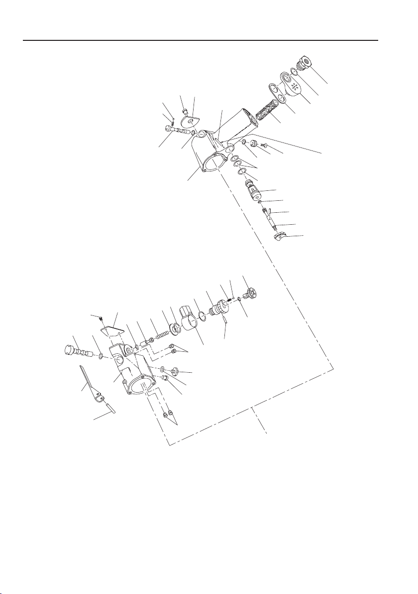
2902P and 2902SB Air Impact Wrench Housing Assembly - Exploded View
1
1
6
7
8
9
10
11
12
12
13
14
15
16
17
18
18
19
20
21
22
22
23
24
25
26
27
28
29
30
31
32
33
34
35
36
37
46
38
39
40
41
42
43
44
45
46
47
Note: Press Pin (45) into and out of
the opposite side of the Housing.
Model 2902 SB
Model 2902P
(Dwg. TPB958-1)
Page 3

2902P and 2902SB Air Impact Wrench Housing Assembly - Parts List
Item Part Description
1 Motor Housing Assembly 2902P-A40 2902SB-A40 30 Reverse Valve Stop --- 401-665
6 Inlet Bushing Assembly 402-565 --- † 31 Bushing Seal --- CE110-210
† • 7 Bushing O-Ring 202-103 --- 32 Grease Fitting --- 130SR-188
8 Exhaust Deector 2902P-23 --- † 33 Detent Ball R000B-263 ---
† • 9 Deector Gasket 202-223 --- † 34 Detent Ball Spring 202-664 ---
† • 10 Long Exhaust Silencer 728-310 --- 35 Reverse Valve Knob 1702P-666 ---
11 Reverse Valve 1702P-329 --- 36 Knob Screw WWA100-77 ---
† • 12 Reverse Valve O-Ring (2) CE110-210 --- 37 Grease Fitting 130SR-188 ---
13 Throttle Valve --- R000B2-302 Throttle Valve Assembly 202-A302 ---
† • 14 Throttle Valve Face --- 401-159 38 Throttle Valve 202-302 ---
† 15 Throttle Valve Spring --- 5081T-151 † • 39 Throttle Valve Face R000BR1C-283 ---
16 Throttle Lever --- 201-273 40 Trigger 5RA-93 ---
17 Throttle Lever Pin --- 502B-120 41 Throttle Valve Retaining Pin AF120-322 ---
† 18 Silencer (4) --- 1702B-311 42 Throttle Valve Bushing 202-503 ---
19 Inlet Assembly Spacer --- R00-35A † • 43 Large Bushing O-Ring 410-283 ---
Air Inlet Assembly --- 2902B-A166 † • 44 Small Bushing O-Ring (2) 202-290 ---
20 Swivel Inlet Body --- 2902B-165 45 Bushing Retaining Pin R100B-120 ---
21 Swivel Inlet Assembly --- 1702B-B166 46 Nameplate 2902P-301 2902SB-301
† 22 Swivel Inlet Seal (2) --- R18LF-21 47 Nameplate Screws (3) --- BN403-302
23 Power Regulator Assembly --- 1702B-A249 † • 48 End Plate Gasket 202-739 401-739
† • 24 Power Regulator Seal --- R00B1-159 * Tune-up Kit (Includes illustrated items:
25 Regulator Retainer --- 201-250 7, 9, 10, 12, 33, 34, 39, 43, 44, 48, 49, 1702P-TK2 ---
† • 26 Detent Spring --- 201-251 50, 53, 57, 64, 67 and 68)
† • 27 Detent Ball --- R000B-263 * Tune-up Kit (Includes illustrated items:
28 Reverse Valve Assembly --- 1702B-A329 14, 15, 18 [4], 22 [2], 24, 26, 27, 28, 31 --- 1702SB-TK2
† • 29 Reverse Valve Seal --- R0BR1C-283 37, 48, 49, 50, 53, 64, 67, and 68)
* Not Illustrated.
† Indicates Tune-up Kit part.
• To keep downtime to a minimum, it is desirable to have on hand certain repair parts. We recommend that you stock one (pair or set) of each
part indicated by a bullet (•) for every four tools in service.
Part Number
2902P 2902SB 2902P 2902SB
Item Part Description
Part Number
04584595_ed3 3
Page 4

4 04584595_ed3
2902P and 2902SB Air Impactool Power Unit - Exploded View
49
48
50
51
52
53
54
55
56
57
58
59
60
61
61
62
62
63
63
64
64
65
65
66
67
68
69
70
71
72
73
74
75
76
77
78
79
80
81
65
62
64
63
82
83
84
85
86
(Dwg. TPA1343)
Page 5

2902P and 2902SB Air Impactool Power Unit - Parts List
Item Part Description Part Number Item Part Description Part Number
† 49 Rear Rotor Bearing Retainer MF-18 • 70 Socket Retaining Ring 1702-425
† 50 Rear Rotor Bearing 401-22 • 71 Retainer Support Ring 1702-426
51 Rear End Plate 201-12 Quick-Change Anvil Assembly (1/4” hex) 1702-A926-4
52 Rotor 401-53 72 Quick-Change Anvil 1702-926-4
† • 53 Vane Packet (Set of 6 Vanes) 401-42A-6 73 Thrust Ring Lock 5C1-853
54 Cylinder 401-3 74 Thrust Ring I0A902A2-932-4
55 Cylinder Dowel HH92-74 • 75 Retaining Sleeve Spring 2U-931-4
56 Front End Plate 201-11 76 Retaining Ball (5/32” diameter steel ball) 2U-696
† 57 Front Rotor Bearing R00H-97 77 R etaining Sleeve 2U-930-4
58 Hammer Frame Washer 1702-706 • 78 Retaining Sleeve Stop 2U-933-4
59 Hammer 1702-724A Quick-Change Anvil Assembly (7/16” hex) 1702-A926-7
60 Hammer Frame Assembly 1702-A703A 79 Quick-Change Anvil 1702-926-7
61 Hammer Pins (2) 1702-704 80 Quick-Change Anvil Body I0A902A5-925
62 Hammer Case Assembly 2902-A727 81 Body Lock Pin I0A902A5-936
63 Hammer Case Bushing 401-641 • 82 Thrust Ring Lock 4U-933-7
* Warning Label WARNING-2-99 83 Thrust Ring 4U-932-7
† 64 Hammer Case Gasket 2902-36 84 Retaining Sleeve Spring 4U-931-7
65 Hammer Case Cap Screw (3) 1702-638 85 Retaining Ball (7/32” diameter steel ball) 2U-722
3/8” Square Drive Anvil Assembly
66
(with Pin-Type Retainer) * Horizontal Hanger 1901-366
† • 67 Socket Retaining Plunger 5020-716 * Vertical Hanger 1901-365
† • 68 Retaining Plunger Spring 401-718 * Socket Adapter (3/8” to 1/2”) 2U-215
3/8” Square Drive Anvil Assembly
69
(with Ring-Type Retainer) for 1/4” hex shank accessories 2U-A925-4
* Not Illustrated.
† Indicates Tune-up Kit part.
• To keep downtime to a minimum, it is desirable to have on hand certain repair parts. We recommend that you stock one (pair or set) of each
part indicated by a bullet (•) for every four tools in service.
1702-P726
1702-A626
86 Retaining Sleeve I0A902A5-930
* Quick-Change Chuck
for 7/16” hex shank accessories 502-A925-7
Parts and Maintenance
When the life of the tool has expired, it is recommended that the tool be disassembled, degreased and parts be separated by material so
that they can be recycled.
Tool repair and maintenance should only be carried out by an authorized Service Center.
Refer all communications to the nearest Ingersoll Rand Oce or Distributor.
Related Documentation
For additional information refer to:
Product Safety Information Manual 04580916.
Product Information Manual 04584769.
Maintenance Information Manual 04584231.
Manuals can be downloaded from www.ingersollrandproducts.com.
04584595_ed3 5
Page 6

Notes:
Page 7

Notes:
Page 8

www.ingersollrandproducts.com
© 2011 Ingersoll Rand
 Loading...