


I n t é g r a t i o n G u i d e
iUP 250 & iUR 250
Ingenico – 28-32 Boulevard de Grenelle - 75015 PARIS Tél. 33(0)1 58 01 80 00 - Fax 33 (0)1 58 01 91 35

The scope of this document is to assist third party integrators when dealing with Ingenico UNattended products (iUN) such as iUP250 and iUR250, both certified PCI PTS 3.x, or others. It offers all information needed for a successful integration of iUP250 and iUR250 products into unattended kiosk machines.
For any sales information please refer to your Ingenico contact into the region.
Updates table
Version |
Date |
Nature of modifications |
Author |
Visa |
1.0 |
17/11/2011 |
First version |
D.GEORGES |
|
2.0 |
01/06/2012 |
Official version |
D.GEORGES |
|
|
|
|
|
|
|
|
|
|
|
|
|
|
|
|
|
|
|
|
|
|
|
|
|
|
|
|
|
|
|
Intégration Guide_iUP250&iUR250 |
2/83 |
Copyright © 2012 Ingenico |
900009151 R11 000 01/1223 |
|
All rights reserved |

Table of contents
1 |
GENERAL ............................................................................................................. |
6 |
||
1.1 |
Definition of acronyms ..................................................................................... |
6 |
||
1.2 iUP250 & iUR250 payment solution presentation .......................................... |
7 |
|||
1.2.1 Diagram of iUP250 & iUR250 connectivity and communications.................. |
8 |
|||
1.2.2 |
Examples of integration ................................................................................ |
9 |
||
1.2.3 |
Services ...................................................................................................... |
10 |
||
1.3 |
Description of modules .................................................................................. |
11 |
||
1.3.1 |
iUP250 ........................................................................................................ |
11 |
||
|
1.3.1.1 |
Technical Hardware characteristics ...................................................... |
12 |
|
|
1.3.1.2 iUP250 output connectors description .................................................. |
14 |
||
|
1.3.1.3 SAM & µSD Installation ........................................................................ |
22 |
||
|
1.3.1.4 |
Buzzer................................................................................................... |
22 |
|
|
1.3.1.5 |
RGB backlight....................................................................................... |
23 |
|
|
1.3.1.6 |
Maintenance Button .............................................................................. |
23 |
|
|
1.3.1.7 |
Cable Protection ................................................................................... |
24 |
|
|
1.3.1.8 |
Antenna Installation .............................................................................. |
25 |
|
|
1.3.1.9 PINPad and Reader interconnectivity ................................................... |
26 |
||
1.3.2 |
iUR250........................................................................................................ |
27 |
||
|
1.3.2.1 |
Technical Hardware Characteristics ..................................................... |
28 |
|
|
1.3.2.2 iUR250 output connectors description .................................................. |
29 |
||
|
1.3.2.3 |
RGB Leds ............................................................................................. |
31 |
|
|
1.3.2.4 iUR250 Optional Lever Lock ................................................................. |
31 |
||
1.4 |
Professional installation Requirement ......................................................... |
32 |
||
2 |
MAIN ACCESSORIES ........................................................................................ |
33 |
||
2.1.1 |
Generality ................................................................................................... |
33 |
||
2.1.2 Optional PINPad-to-Reader USB cable ...................................................... |
33 |
|||
2.1.3 |
iUP250 Power supply ................................................................................. |
33 |
||
2.1.4 |
Stand-by management cable ...................................................................... |
33 |
||
2.1.5 |
Optional Pinshield....................................................................................... |
34 |
||
3 |
SOFTWARE ........................................................................................................ |
37 |
||
3.1 |
iUP250.............................................................................................................. |
37 |
||
3.1.1 |
Software Architecture ................................................................................. |
38 |
||
3.1.2 Secure management of software ................................................................ |
39 |
|||
3.1.3 |
Operating system........................................................................................ |
40 |
||
3.1.4 |
TELIUM MANAGER ................................................................................... |
41 |
||
3.1.5 |
Software downloading ................................................................................ |
43 |
||
3.1.6 |
Development station ................................................................................... |
45 |
||
3.2 |
iUR250 ............................................................................................................. |
|
47 |
Intégration Guide_iUP250&iUR250 |
3/83 |
Copyright © 2012 Ingenico |
|
900009151 R11 000 01/1223 |
|
All rights reserved |
|

3.2.1 |
Software architecture .................................................................................. |
48 |
|
3.2.2 |
Software security management .................................................................. |
48 |
|
3.2.3 |
Operating system........................................................................................ |
49 |
|
4 |
TERMINAL MANAGEMENT SYSTEM ............................................................... |
50 |
|
4.1 |
Introduction..................................................................................................... |
50 |
|
4.2 |
Basic functions ............................................................................................... |
50 |
|
4.3 |
Advanced functions ....................................................................................... |
50 |
|
4.4 |
Customers savings with Ingenico TMS solution ......................................... |
50 |
|
5 INSTALLATION PROCEDURE IN KIOSKS ....................................................... |
51 |
||
5.1 |
Security requirement...................................................................................... |
51 |
|
5.2 |
Kiosk mechanical requirements.................................................................... |
51 |
|
5.3 |
General installation recommendations......................................................... |
51 |
|
5.4 |
Kiosk suggested layouts for iUR250 IUP250................................................ |
51 |
|
5.4.1 Vertical PINPad above the reader .............................................................. |
52 |
||
5.4.2 Leaned backward PINPad above vertical reader........................................ |
53 |
||
5.4.3 Leaned forward reader above leaned backward PINPad ........................... |
54 |
||
5.4.4 Optional pinshield layout considerations..................................................... |
55 |
||
5.5 |
Kiosk water ingress consideration ............................................................... |
55 |
|
5.6 |
Kiosk cooling consideration.......................................................................... |
55 |
|
5.7 |
Kiosk grounding consideration..................................................................... |
56 |
|
6 ASSEMBLY PROCEDURE FOR IUR250 CARD READER ................................ |
57 |
||
6.1 |
Kiosk minimum volume for iUR 250.............................................................. |
57 |
|
6.2 |
Kiosk preparation for iUR250 installation..................................................... |
58 |
|
6.3 |
Installing the Reader iUR250 ......................................................................... |
59 |
|
6.4 |
Water evacuation consideration.................................................................... |
60 |
|
6.5 |
Connecting the iUR250 to the kiosk ground ................................................ |
61 |
|
7 ASSEMBLY PROCEDURE FOR IUP250 PINPAD ............................................. |
62 |
||
7.1 |
Kiosk minimum volume for iUP250............................................................... |
62 |
|
7.2 |
Kiosk preparation for iUP250 new installation............................................. |
63 |
|
Intégration Guide_iUP250&iUR250 |
4/83 |
Copyright © 2012 Ingenico |
900009151 R11 000 01/1223 |
|
All rights reserved |

7.3 Installing the iUP250 PINPad in new kiosk ................................................... |
64 |
7.4Kiosk preparation for iUP250 installation as replacement of i9530 product 65
7.5 |
Installing the iUP250 PINPad as replacement of i9530................................ |
66 |
7.6 |
Connecting the iUP250 to the kiosk ground................................................. |
67 |
7.7 |
Installing the optional pinshield .................................................................... |
68 |
7.7.1 Installing the standard pinshield.................................................................. |
69 |
|
7.7.2 Installing the Lighting pinshield ................................................................... |
70 |
|
8 INFORMATIONS ON IUC150 OR IUC180 CONTACLESS UNATTENDED |
|
|
MODULES................................................................................................................. |
71 |
|
8.1.1 Kiosk mechanical requirements .................................................................. |
71 |
|
9 MAINTENANCE .................................................................................................. |
72 |
|
9.1 |
Configuration .................................................................................................. |
72 |
9.2 |
Products Commisionning .............................................................................. |
72 |
9.3 |
Reactivation .................................................................................................... |
73 |
9.4 |
Operating life................................................................................................... |
73 |
10 |
CLEANING INSTRUCTIONS ........................................................................... |
74 |
11 |
DISASSEMBLING THE PRODUCTS ACCORDING TO WEEE DIRECTIVE .. |
75 |
11.1 iUP250 End-of–life disassembly instructions ........................................... |
75 |
|
11.2 |
IUR250 End-of–life disassembly instructions ........................................... |
77 |
12 |
STANDARDS ................................................................................................... |
79 |
12.1 |
Electrical consumptions ............................................................................. |
79 |
12.2 |
Temperature and humidity.......................................................................... |
79 |
12.3 |
Environmental specification continued ..................................................... |
80 |
12.4 EC standard compliance marking .............................................................. |
80 |
|
12.5 |
IC statements ............................................................................................... |
81 |
12.6 Environment (WEEE, Batteries and Packaging) ....................................... |
83 |
|
12.7 |
Security of your terminal............................................................................. |
83 |
Intégration Guide_iUP250&iUR250 |
5/83 |
Copyright © 2012 Ingenico |
900009151 R11 000 01/1223 |
|
All rights reserved |

1GENERAL
1.1DEFINITION OF ACRONYMS
EMC |
Electro Magnetic Compatibility |
|
|
|
|
EMV |
Europay, Mastercard, Visa |
|
|
|
|
EVA |
European Vending Association |
|
|
|
|
GND |
Ground |
|
|
|
|
GPRS |
General Packet Radio Service |
|
|
|
|
GSM |
Global System for Mobile communications |
|
|
|
|
LCD |
Liquid Crystal Display |
|
|
|
|
LLT |
Local Loading Tool |
|
|
|
|
MDB |
Multi Drop Bus |
|
|
|
|
PCI |
Payment Card Industry |
|
|
|
|
PIN |
Personal Identification Number |
|
|
|
|
PSTN |
Public Switched Telephone Network |
|
|
|
|
PTS |
PIN Transaction Security |
|
|
|
|
RAM |
Random Access Memory |
|
|
|
|
RS232 |
Recommended Standard 232. A standard for serial binary communications |
|
|
|
|
SAM |
Secure Access Module – the chips storing the electronic cash register in a |
|
stored value scheme such as Moneo, Proton or VISA Cash. |
||
|
||
SMA |
SubMiniature version A |
|
|
|
|
USB |
Universal Serial Bus |
|
|
|
Intégration Guide_iUP250&iUR250 |
6/83 |
Copyright © 2012 Ingenico |
900009151 R11 000 01/1223 |
|
All rights reserved |

1.2IUP250 & IUR250 PAYMENT SOLUTION PRESENTATION
The iUN series is the new range of Ingenico UNattended (iUN) devices to offer payment into any kiosk through any segments (petrol, transport, vending, parking, etc.).
The two first modules offered for contact cards and PIN management are:
A PINPad, the iUR250,
An Hybrid Card Reader, the iUR250.
These compact devices are designed to fit everywhere, thanks to an easy installation, respectful of EVA standard (iUP250) and IMB standard (iUR250). Usage can be indoor or outdoor, resisting to harsh environment.
Both products, certified PCI PTS 3.x, must be installed together into an environment that must comply with several rules described into this document to remain PCI PTS 3.X certified.
Remarks:
Additional peripherals can be added to build a complete solution such as printer or bar code reader. Ingenico does not provide these devices so far but they can be connected to the iUP250 (through, USB, or RS232).
Ingenico is also offering other iUN modules dedicated to contactless like iUC150 or iUC180. The iUC150 is the preferred contactless peripheral for the iUP250+iUR250 system.
The iUN series is the next generation of Ingenico leveraging of experience from previous product ranges, i9500 series or CAD30 series, to renew your experience of unattended payment.
Intégration Guide_iUP250&iUR250 |
7/83 |
Copyright © 2012 Ingenico |
900009151 R11 000 01/1223 |
|
All rights reserved |
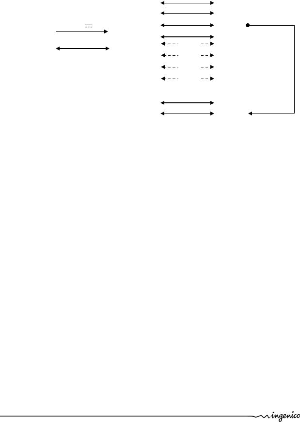
1.2.1Diagram of iUP250 & iUR250 connectivity and communications
|
|
|
|
|
|
|
|
|
|
|
|
|
|
|
|
|
|
|
Ethernet |
|
|
|
|
|
|
|
|
|
|
|
|
|
|
|
|
|
|
|
1USB device |
|
|
|
|
|
|
|
|
|
|
|
|
|
|
|
|
|
|
|
|
|
|
|
12 – 30 V |
|
3A |
|
|
|
|
|
|
4 USB host |
|||||||
|
|
Power supply |
|
|
|
|
|
|
|
||||||||||
|
|
|
|
|
|
|
|
|
|
||||||||||
|
|
|
|
|
|
|
|
|
|
|
|
|
|
|
|
|
|
|
|
|
|
|
|
|
|
|
|
|
|
|
|
|
|
Keypad/display |
|
Serial port com0 |
|||
|
|
|
|
|
|
|
|
|
|
|
|
|
|
|
|
||||
|
|
MDB slave |
|
|
|
|
|
|
|
|
|
|
|
|
|
iUR250 |
(Option) |
GSM / GPRS |
|
|
|
|
|
|
|
|
|
|
|
|
|
|
|
|
|
|
|
|
|
|
|
|
|
|
|
|
|
|
|
|
|
|
|
|
|
|
|
(Option) |
Bluetooth |
Main Power |
|
|
|
|
|
|
|
|
|
|
|
|
|
|
|
(Option) |
MDB master |
||
|
|
|
|
|
|
|
|
|
|
|
|
|
|
|
|||||
|
|
|
|
|
|
|
|
|
|
|
|
|
|
|
|||||
supply |
|
|
|
|
|
|
|
|
|
|
|
|
|
|
|
||||
|
|
|
|
|
|
|
|
|
|
|
|
|
|
|
|
|
|||
|
|
|
|
|
|
|
|
|
|
|
|
|
|
|
|
|
|
(Option) |
Serial port com2 |
|
|
|
|
|
|
|
|
|
|
|
|
|
|
|
|
|
|
||
|
|
|
|
|
|
|
|
|
|
|
|
|
|
|
|
|
|
||
|
|
|
|
|
|
|
|
|
|
|
|
|
|
Card Reader |
|
|
|||
|
|
|
|
|
|
|
|
|
|
|
|
|
|
|
|
iUR250 |
|
Serial port com0 |
|
|
|
|
|
|
|
|
|
|
|
|
|
|
|
|
|
|
|
|
|
|
|
|
|
|
|
|
|
|
|
|
|
|
|
|
|
|
|
|
USB device |
|
|
|
|
|
|
|
|
|
|
|
|
|
|
|
|
|
|
|
|
|
|
|
|
|
|
|
|
|
|
|
|
|
|
|
|
|
|
|
|
|
|
|
|
|
|
|
|
|
|
|
|
|
|
|
|
|
|
|
|
|
|
|
|
|
|
|
|
|
|
|
|
|
|
|
|
|
|
|
|
Intégration Guide_iUP250&iUR250 |
8/83 |
Copyright © 2012 Ingenico |
900009151 R11 000 01/1223 |
|
All rights reserved |
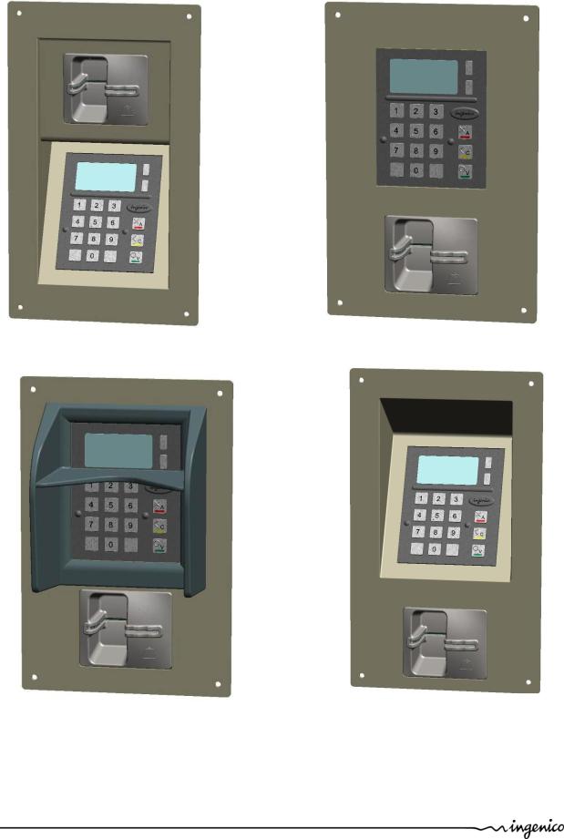
1.2.2 Examples of integration
Intégration Guide_iUP250&iUR250 |
9/83 |
Copyright © 2012 Ingenico |
900009151 R11 000 01/1223 |
|
All rights reserved |

1.2.3 Services
|
|
Installation and exploitation |
|
|
|
Softwares |
|
Training |
|
OEMC/M²OS development ( days) |
|
|
EMV Level 2 package (2 days) |
||
|
|
Development workstation SDK |
|
Support |
Hot-line support |
||
|
Technical assistance |
||
|
|||
After-Sales Service |
|
Fixed cost repair of iUN products |
|
|
|
User licence |
|
|
|
Installation and commissioning |
|
Downloading server centre |
|
User training |
|
|
Hot-line support |
||
|
|
Technical assistance |
|
|
User licence for local loading tool, LLT |
||
|
User licence for applications software |
||
|
User licence for M²OS |
||
Softwares / Licences |
|
Licence for software signature tool, SAT |
|
|
Licence for "EMV Level 2 package " |
||
|
|
Licence for TCP/IP |
|
|
|
… |
|
Intégration Guide_iUP250&iUR250 |
10/83 |
Copyright © 2012 Ingenico |
900009151 R11 000 01/1223 |
|
All rights reserved |
1.3 DESCRIPTION OF MODULES
1.3.1 iUP250
Front view |
Rear view |
Intégration Guide_iUP250&iUR250 |
11/83 |
Copyright © 2012 Ingenico |
900009151 R11 000 01/1223 |
|
All rights reserved |

1.3.1.1 Technical Hardware characteristics
iUP250 technical characteristics:
|
Mass |
|
700 g |
|
|
|
|
|
|
||
|
|
|
|
|
|
|
Dimensions |
|
132 x 123 x 46 mm (height x width x |
||
|
|
||||
|
|
depth) |
|
|
|
|
|
|
|
|
|
|
|
|
|
|
|
Operating conditions |
|
|
|
||
|
|
|
|
|
|
|
Operational temperature* |
|
-20°C,+55°C |
|
|
|
|
|
|
|
|
|
Functional temperature* |
|
-20°C, +65°C |
|
|
|
|
|
|
|
|
|
Max relative humidity |
|
85% at 55°C, non-condensing |
|
|
|
|
|
|
|
|
|
Maximum backward |
|
30 degrees from vertical |
|
|
|
leaning |
|
|
||
|
|
|
|
|
|
|
|
|
|
|
|
|
Power Supply |
|
12 – 30 V max |
3A |
|
|
|
|
|
|
|
|
Platform |
|
Telium2 |
|
|
|
|
|
|
|
|
|
Memory |
|
16 Mb SDRAM and 128 Mb Flash |
|
|
|
|
|
|
|
|
|
|
|
Keys: 17 metallic keys |
|
|
|
|
|
128 x 64 graphic display |
|
|
|
|
|
RGB Backlight |
|
|
|
|
|
Buzzer |
|
|
|
|
|
RGB led internal status indicator |
|
|
|
Functionality |
|
1 Maintenance Button |
|
|
|
|
||||
|
|
|
|
|
|
|
|
|
µSD |
|
|
|
|
|
|
|
|
|
|
|
2 SAM |
|
|
|
|
|
1 SIM (optional) |
|
|
|
|
|
1 Jack for external lighting |
|
|
|
|
|
wake-up mechanism on RS232 |
|
|
|
|
|
connectors |
|
|
|
|
|
|
|
|
Intégration Guide_iUP250&iUR250 |
12/83 |
Copyright © 2012 Ingenico |
900009151 R11 000 01/1223 |
|
All rights reserved |

Ethernet
GSM/GPRS (optional)
Bluetooth (optional)
Link
4 USB host (1.2 A total max)
1 USB device
2x RS232 (1 optional) MDB slave
MDB Master (optional)
* 55°C is a maximum using temperature for user safety (IEC 60950). The product is operational up to 65°C with no tampering issue.
Storage conditions
Storage temperature |
-20°C,+65°C |
|
|
Max relative humidity |
85% at 55°C, non-condensing |
|
|
Intégration Guide_iUP250&iUR250 |
13/83 |
Copyright © 2012 Ingenico |
900009151 R11 000 01/1223 |
|
All rights reserved |

1.3.1.2 iUP250 output connectors description
COM0 link |
|
MDB slave |
|
MDB master |
|
|
|
|
|
SIM
2 SAM
|
|
µSD |
Pinshield light output |
COM2 Link |
|
Intégration Guide_iUP250&iUR250 |
14/83 |
Copyright © 2012 Ingenico |
900009151 R11 000 01/1223 |
|
All rights reserved |
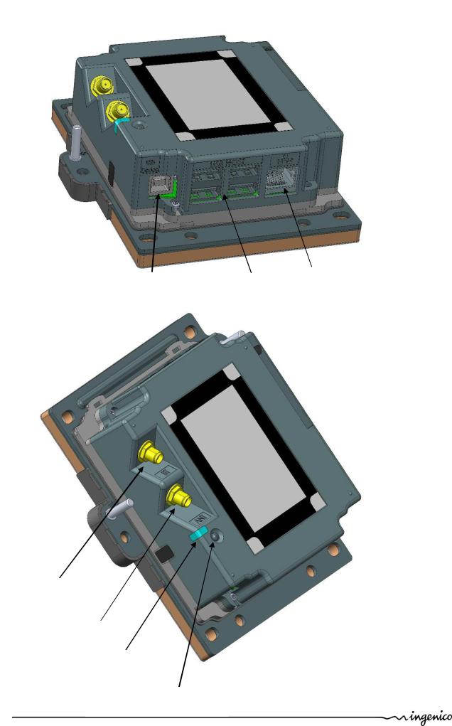
USB Device |
|
USB hosts |
|
|
|
|
Ethernet |
||
|
|
|
|
|
|
|
|
|
|
Bluetooth Antenna
GSM Antenna
LLT/Maintenance LED
LLT/Maintenance Button
Intégration Guide_iUP250&iUR250 |
15/83 |
Copyright © 2012 Ingenico |
900009151 R11 000 01/1223 |
|
All rights reserved |
1.3.1.2.1 Ethernet
The IUP250 PINPad unit can be connected to Ethernet. The connector type is shielded RJ45.
The Ethernet cable is standard and not provided. The Ethernet cable must be shielded.
1.3.1.2.2 USB device
The IUP250 PINPad unit can be connected by type B USB.
1.3.1.2.3 USB host
The iUP250 PINPad unit can drive 4 USB accessories. The connector is standard type A.
The power available is limited to 1.2A Max dispatched between the 4 USB.
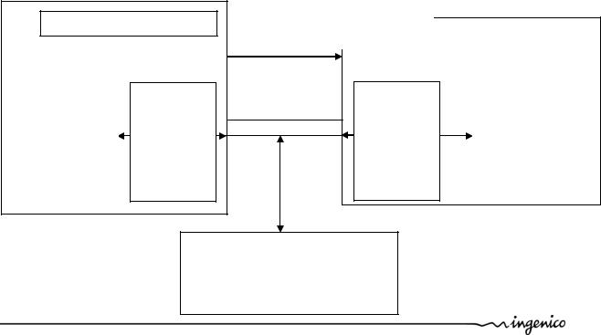
1.3.1.2.4 Wake-up mechanism
iUP250 is design to save power thanks to a “stand-by mode”.
To wake-up iUP250, press green key or use Wake-up mechanism. Pin 2 of COM0 link & COM2 link drive the wake-up mechanism.
Wake-up pin state |
|
|
|
Hz (high impedance) |
Stand-by authorized |
|
|
Drive to “0” |
Wake-up / Stand-by unauthorized |
|
|
The Wake-up pin is drive to “0” by the one asking the wake-up.
It could be driven by iUR250, iUP250 or any devices designed to be compliant (Host device…).²
PINPad |
|
USB |
|
iUP 250 |
|
||
|
|
||
|
COM0 & 2 |
||
HZ => Stand-by |
1 |
- GND |
|
2 |
- Wake-up |
||
« 0 » => Wake-up |
|||
3 |
|
||
|
|
||
|
4 |
|
|
|
5 |
|
|
|
6 |
|
|
Do not connect |
Card Reader |
||
DC PLUG |
|
||
|
iUR 250 |
||
|
|
||
USB |
|
||
COM0 |
|
||
1 |
- GND |
HZ => Stand-by |
|
2 |
- Wake-up |
||
« 0 » => Wake-up |
|||
3 |
|
||
|
|
||
4 |
|
|
|
5 |
|
|
|
6 |
|
|
|
Any devices design to be compliant.
HZ => Stand-by « 0 » => Wake-up
Intégration Guide_iUP250&iUR250 |
16/83 |
Copyright © 2012 Ingenico |
900009151 R11 000 01/1223 |
|
All rights reserved |
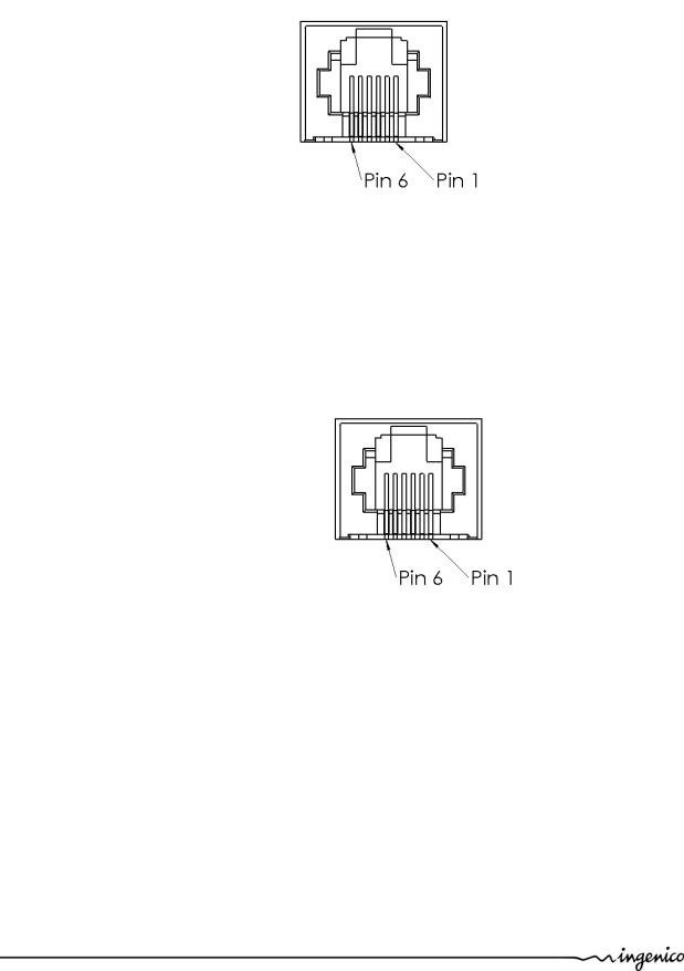
1.3.1.2.5 COM0 link
The iUP250 PINPad unit can be connected to serial port COM0. The connector type is RJ11.
Pin N° |
Function |
|
|
1 |
GND |
|
|
2 |
Wake-up |
|
|
3 |
RXD |
|
|
4 |
TXD |
|
|
5 |
CTS |
|
|
6 |
RTS |
|
|
1.3.1.2.6 COM2 link (optional)
The iUP250 PINPad unit can be connected to serial port COM2 if the option is available. The connector type is RJ11.
Pin N° |
Function |
|
|
1 |
GND |
|
|
2 |
Wake-up |
|
|
3 |
RXD |
|
|
4 |
TXD |
|
|
5 |
CTS |
|
|
6 |
RTS |
|
|
Intégration Guide_iUP250&iUR250 |
17/83 |
Copyright © 2012 Ingenico |
900009151 R11 000 01/1223 |
|
All rights reserved |
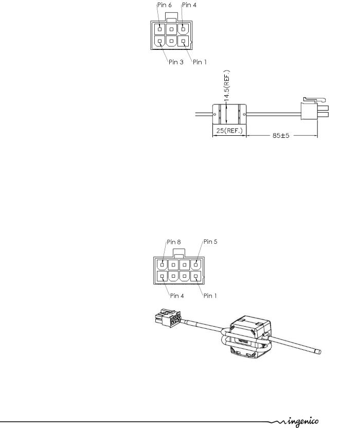
1.3.1.2.7 MDB Slave
iUP250 PINPad unit can be connected by MDB slave. The connector type is MDB 6 pins (Mini – Fit series 87827 (MOLEX)). iUP250 is powered on the MDB connectors by power supply 12 to 30V DC (30V is a maximum).
Pin N° |
Function |
|
|
1 |
Vin |
|
|
2 |
GND |
|
|
3 |
NC |
|
|
4 |
MDBS_RXD |
|
|
5 |
MDBS_TXD |
|
|
6 |
MDBS_COMMUN |
|
|
A ferrite B & F ELECTRONICS CO., LTD. ref MD-05-265C or equivalent must be added on the power cable.
1.3.1.2.8 MDB master (optional)
The iUP250 PINPad unit can be connected by MDB master if option available. The connector type is MDB master 8 pins (Mini – Fit series 87827 (MOLEX)).
iUP250 does not support EXE power supply. A ferrite Würth ref 74271222 or equivalent must be added with two turns on the cable.
Pin N° |
Function |
|
|
1 |
NC |
|
|
2 |
NC |
|
|
3 |
NC |
|
|
4 |
NC |
|
|
5 |
MDBM_RXD |
|
|
6 |
ISO_GND |
|
|
7 |
MDBM_TXD |
|
|
8 |
ISO_GND |
|
|
Intégration Guide_iUP250&iUR250 |
18/83 |
Copyright © 2012 Ingenico |
900009151 R11 000 01/1223 |
|
All rights reserved |
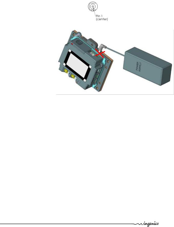
1.3.1.2.9 Pinshield light output
This connector is used to plug the pinshield with optional lighting.
|
Pin N° |
|
|
|
Function |
||
|
|
|
|
|
|
|
|
|
1 |
|
|
|
5V |
||
|
|
|
|
|
|
|
|
|
2 |
|
|
HZ |
|
Light off |
|
|
|
||||||
|
|
|
|
|
|
|
|
|
|
|
“0” |
|
Light on |
|
|
|
|
|
|
|
|
||
|
|
|
|||||
|
|
|
|
|
|
|
|
WARNING:
This DC Jack is only an output power supply for the Lighting pinshield.
Plugin a DC power could damage the iUP250.
Intégration Guide_iUP250&iUR250 |
19/83 |
Copyright © 2012 Ingenico |
900009151 R11 000 01/1223 |
|
All rights reserved |

1.3.1.2.10Bluetooth (optional)
When the iUP250 is ordered with Bluetooth option, it must be connected to an external Bluetooth antenna.
Ingenico can provide an antenna, or a standard one can be used. This standard Antenna must have an impedance of 50 Ohm and a maximum gain of 0 dBi.
Ingenico recommended antennas:
Antenna |
manufacturer |
model |
gain |
impedance |
Minimum |
Ingenico |
|
type |
|
|
|
|
cable |
Reference |
|
|
|
|
|
|
length |
|
|
bipolar |
EAD |
FBTS35024- |
0dBi |
50ohm |
0 |
192023282 |
|
SM-ST |
|||||||
|
|
|
|
|
|
||
|
|
|
|
|
|
|
Intégration Guide_iUP250&iUR250 |
20/83 |
Copyright © 2012 Ingenico |
900009151 R11 000 01/1223 |
|
All rights reserved |
GPRS (optional)
When the PINPad unit is provided with GPRS functionality (configuration upon request), the external antenna is not provided with the unit.
Ingenico can provide an antenna, or a standard one can be used. This standard Antenna must have an impedance of 50 Ohm and a maximum gain of 3.5 dBi.
The SIM used for GSM functionality must be assigned to SIM slot.
Ingenico recommended antennas:
Antenna |
manufacturer |
model |
gain |
impedance |
Minimum |
Ingenico |
|
type |
|
|
|
|
cable |
Reference |
|
|
|
|
|
|
length |
|
|
|
|
|
|
|
|
|
|
bipolar |
AMPHENOL |
90-00234 |
1.7dBi |
50ohm |
0 |
179900131 |
|
|
|
|
|
|
|
|
|
bipolar |
HIRSHMANN |
MCA 18 90 |
2.1dBi |
50ohm |
2.5m |
189968573 |
|
MP |
|||||||
|
|
|
|
|
|
||
|
|
|
|
|
|
|
|
bipolar |
Giga concept |
GC300M- |
2.2dBi |
50ohm |
2.5m |
189963487 |
|
011-2500 |
|||||||
|
|
|
|
|
|
||
|
|
|
|
|
|
|
Intégration Guide_iUP250&iUR250 |
21/83 |
Copyright © 2012 Ingenico |
900009151 R11 000 01/1223 |
|
All rights reserved |
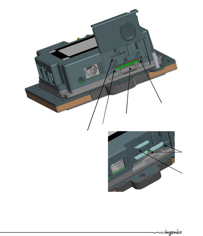
1.3.1.3 SAM & µSD Installation
1.Disconnect the iUP250 from the main power supply.
2.Open the SAM door by removing the screw.
3.Insert the SAM cards in SAM slot 1 and /or slot 2
4.Insert µSD card in µSD slot
5.Insert SIM card in SIM slot.
6.Slide the SAM door and screw.
SAM slot 2
µSD card slot
SIM slot |
SAM slot 1 |
|
|
|
|
For SAM/SIM cards, take care of cards orientation and do not push in excess the cards. After insertion, the cards position is 4 mm
out of the products as shown on picture.
1.3.1.4 Buzzer
The buzzer is controlled by application. The frequency depends of software.
Cut angle orientation (SAMs)
Cut angle orientation (SIM)
Intégration Guide_iUP250&iUR250 |
22/83 |
Copyright © 2012 Ingenico |
900009151 R11 000 01/1223 |
|
All rights reserved |

1.3.1.5 RGB backlight
The iUP250 has a RGB backlight controlled by applications.
Red backlight is used to indicate the following priority information:
·Red backlight on steady: product has been tampered (Key erased, irruption).
·Red backlight flashing slowly: product is disabled (Keys erased, no irruption).
·Red backlight flashing quickly: product is out of order (Commissioning needed).
1.3.1.6 Maintenance Button
The iUP250 has a maintenance button on the back.
-To enter LLT mode, press the button at power up or at restart, until the red led lights on.
-To enter Maintenance mode, press the button at power up or at restart, until the red led starts blinking.
-To restart the product, press the button until the blue led lights on.
Intégration Guide_iUP250&iUR250 |
23/83 |
Copyright © 2012 Ingenico |
900009151 R11 000 01/1223 |
|
All rights reserved |
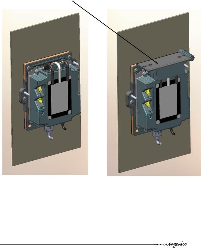
1.3.1.7 Cable Protection
A cable sealing sleeve is provided with iUP250 to protect the top of product against water runoff.
Connect the cables, and snap in the part on the rear cover to cover the cables. This sleeve also holds the antenna tool for GPRS and BT options.
Cable sealing sleeve clipped on back cover
Intégration Guide_iUP250&iUR250 |
24/83 |
Copyright © 2012 Ingenico |
900009151 R11 000 01/1223 |
|
All rights reserved |
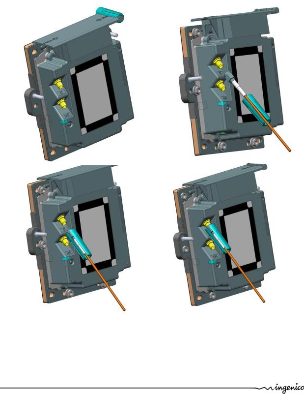
1.3.1.8 Antenna Installation
A tool is provided to help screwing the external antenna.
1.Remove the antenna tool from the cable sleeve.
2.Insert the SMA antenna cable through the slot of the antenna tool.
3.Slide the antenna tool over the SMA Cable connector.
4.Screw the cable.
Intégration Guide_iUP250&iUR250 |
25/83 |
Copyright © 2012 Ingenico |
900009151 R11 000 01/1223 |
|
All rights reserved |
 Loading...