

Owner’s Guide
CAS 3.1 AND CAS 2.1

2
CAS 3.1/CAS 2.1
CAS Series loudspeakers incorporate several innovative
technologies that, when combined with many hours of subjective
listening evaluations and our rigorous engineering standards,
result in a loudspeaker that realistically and accurately reproduces
the signal source with minimal distortion and coloration.
Ceramic Metal MatrixDiaphragms™(C.M.M.D.)
For decades,loudspeaker engineers have known that the ideal
transducer should be stiff,yet light,and have high internal
damping (damping is a material’s ability to absorb energy).
Infinity’s C.M.M.D. transducer is a significant advance in
transducer technology.Ceramic, a class of material new to
loudspeakers,offers better performance than that of other
materials.Ceramic is stiffer than metals and lighter than plastics
and typical composite materials; it also offers improved damping.
These ceramic-based transducers take us a giant step closer to
the ever-elusive “ideal transducer.”
In tweeters,C.M.M.D.technology offers stiffness and damping
superior to that of traditional metals and soft-dome materials.
In woofer and midrange applications,it offers accurate pistonic
operation over the entire frequency range of the driver,
completely eliminating coloration due to cone breakup and
dramatically reducing distortion.And when ceramic-metal-matrix
transducers are exposed to moisture, sunlight or extreme
temperatures,their performance does not deteriorate.
In addition to ceramic diaphragms,all the transducers incorporate
rigid cast-frames that,through our FEA computer modeling and
scanning-laser-vibrometer measurements,have been optimized
to reduce resonances.This ensures minimal distortion and
incomparable performance.
The Baffle Isolation System
™
Designing a high-performance in-wall loudspeaker poses a
unique problem…the wall itself.Drywall is not intended to be a
loudspeaker enclosure.It is neither stiff nor rigid and tends to
resonate,or vibrate, severely when typical in-wall speakers are
used.Wall resonance is generally caused by two things.One is by
sound emanating from the back of the loudspeaker bouncing
around the inside of the wall cavity. Filling the wall with a
suitable damping material, such as fiberglass,helps to minimize
this problem.The second – and more difficult problem to solve –
results from the energy transfer caused by the mechanical
coupling of the loudspeaker to the wall. Infinity’s Baffle Isolation
System solves this problem by mechanically de-coupling the
baffle from the wall.A compliant suspension system “floats” the
baffle within the mounting frame and greatly reduces the energy
transfer.Four of these assemblies – one at each corner of the
baffle – form the isolation system.These assemblies reduce wall
resonance in much the same way the suspension system of a car
isolates the passenger cabin from road vibration.
Noryl®Baffle and Cast-Aluminum Woofers
The baffle of most in-wall speakers is typically made of ABS
plastic, which is prone to flexing.Yet another resonance for our
engineers to tame! After exhaustive research, a two-pronged
attack was chosen. First,the CAS baffles are constructed of
Noryl, a high-stiffness thermoplastic resin. Noryl is 40% stiffer
than typical ABS and has higher internal damping, resulting in a
rigid, but acoustically “dead,” baffle.Also, Noryl’s resistance to
extreme heat and moisture make it an ideal choice for
architectural applications.Second, the cast-aluminum woofer
frames have been designed to enhance the structural rigidity of
the entire baffle.Structural ribs on the baffle integrate with
mounting bosses used to attach the cast-aluminum frame,which
further strengthens the entire assembly.
Listening Window Selector
™
There should be no question that the CAS loudspeakers are the
most “room-friendly”in-wall loudspeakers available.However,
speaker location and listener positions vary so much that even
the CAS loudspeakers may need the occasional adjustment.
Therefore, Infinity has developed a Listening Window Selector
that allows the speaker to be fine-tuned for optimal performance
and deliver smooth,accurate sound reproduction, regardless of
where the speaker is installed or the listener is positioned.
Room-Friendly Acoustical Design
One characteristic of forward-facing loudspeakers is that the
sound output lessens as one moves away from the principal axis.
This happens both horizontally and vertically and it means that
radiated sounds that are reflected from the floor,ceiling and side
walls will be lower in amplitude than direct,forward sound.This
is usually a good thing. But, if the dispersion characteristics of
the loudspeaker are different at various frequencies,the sound
quality of the reflected sounds will be very different both from
each other and from the first (i.e.,direct) sound.The ears don’t
ignore these differences;they perceive them as coloration,or as
sound quality that’s been degraded.Intermezzo loudspeakers
have been carefully designed to maintain a directional pattern
that is similar at every important angle,on- and off-axis.The
positive result is that both direct and reflected sounds arriving at
the listeners’ears have similar timbral signatures.
Completing the Experience
The technology and performance that make Infinity CAS
loudspeakers ideal for music listening also make them the
perfect digital multichannel loudspeaker system.To complete a
home theater system, Infinity has designed, to the same standards
as for the CAS,several powered subwoofers.Ask your Infinity
dealer which model is best for your application.
We hope you enjoyed this brief introduction to the technology
of CAS loudspeakers.If you would like to further explore their
technology and design, please ask your Infinity dealer for the
C.M.M.D.and CAS White Papers.The White Papers can also be
downloaded from Infinity’s Web site at www.infinitysystems.com.
TECHNOLOGY
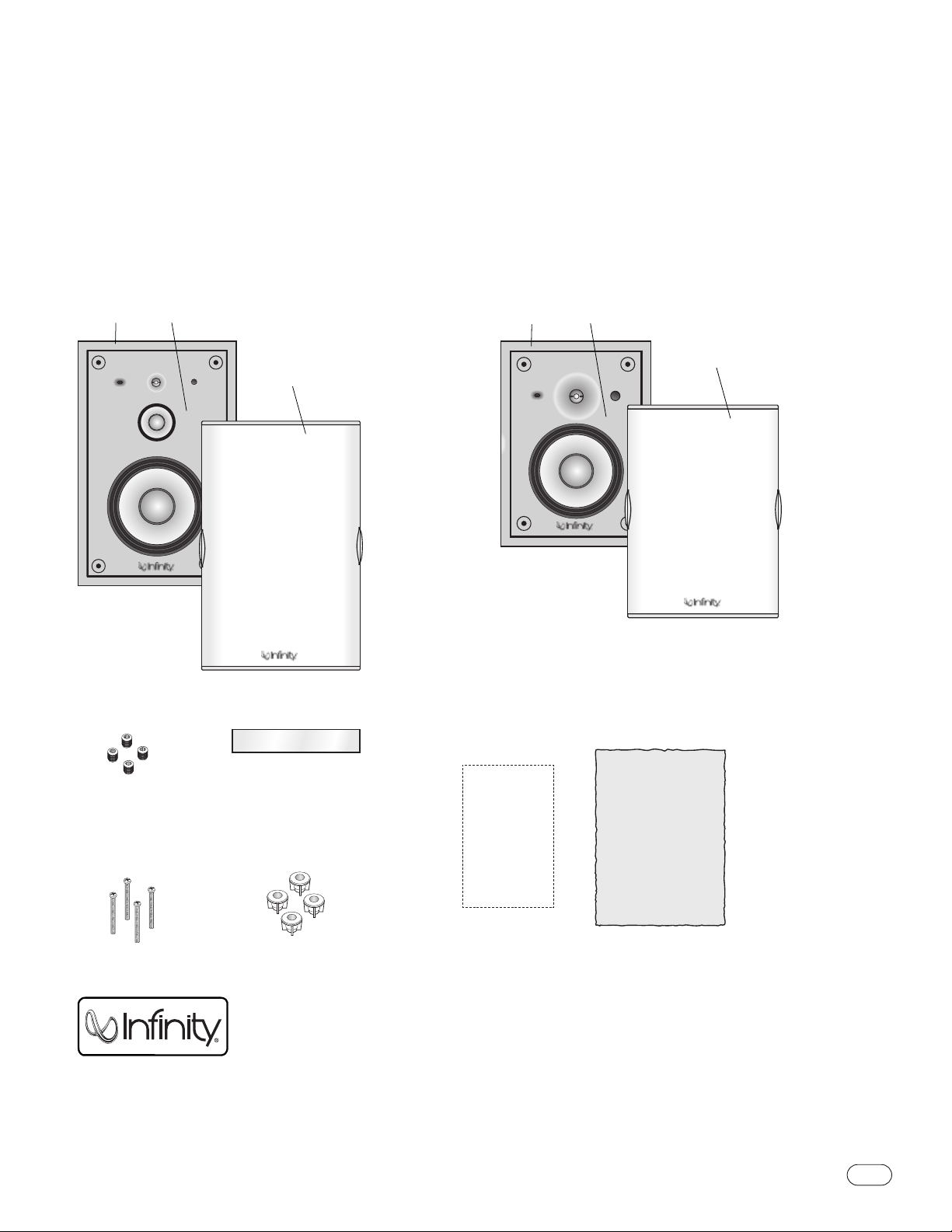
Unpacking the Product
Finish unpacking the speakers and check the contents.If you
suspect damage from transit,report it immediately to your
dealer. Keep the shipping carton and packing materials for
future use.
Included
3
CAS 3.1/CAS 2.1
BAFFLE
ASSEMBLY
MOUNTING
FRAME
GRILLE
MOUNTING
FRAME
BAFFLE
ASSEMBLY
GRILLE
CAS 3.1
CAS 2.1
MOUNTING
FRAME
BAFFLE
ASSEMBLY
GRILLE
MOUNTING
FRAME
GRILLE
BAFFLE
ASSEMBLY
CARDBOARD SHIM
INSERTS (4)
SCREWS (4)
TEMPLATE FIBERGLASS
INSULATION
GRILLE INSERTS (4)
EXTRA LOGOS
GRILLE INSERTS (4)
CARDBOARD SHIM
SCREWS (4)
INSERTS (4)
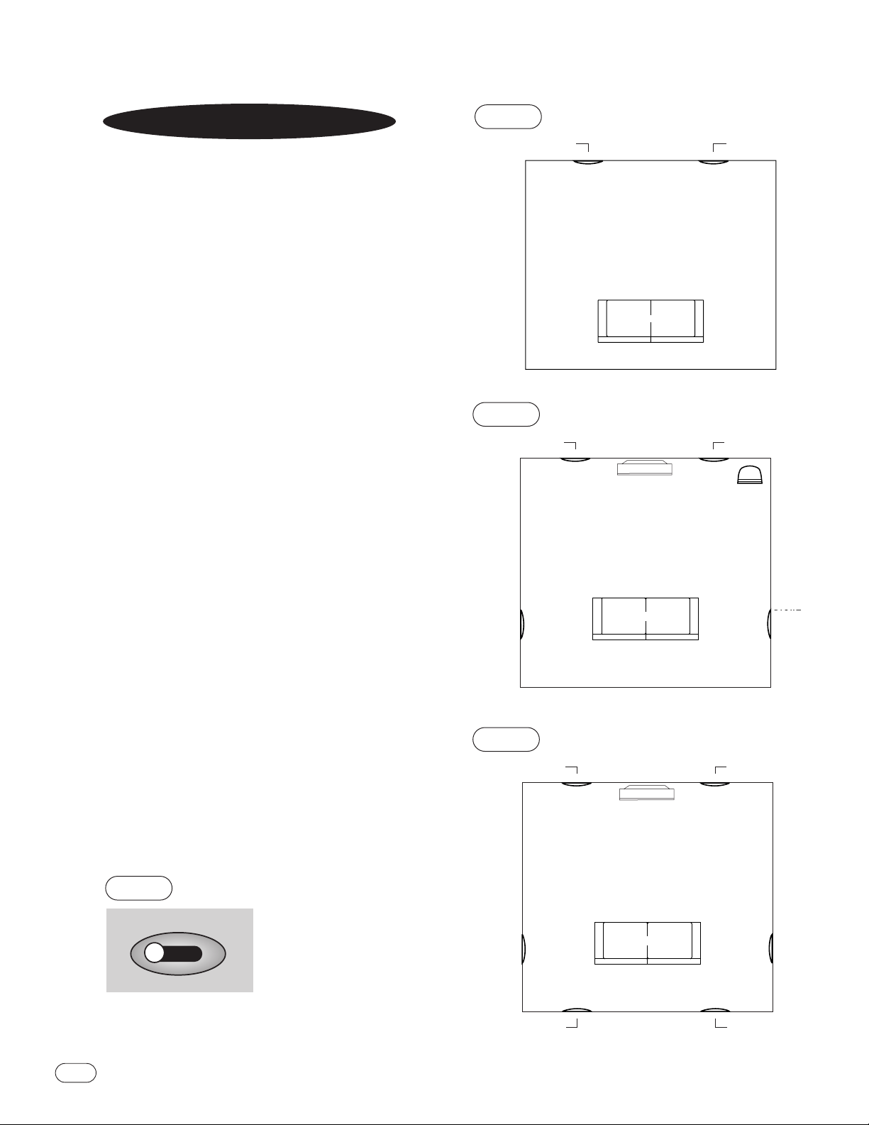
The Infinity CAS in-wall speakers are designed to offer excellent
performance in any listening room or home theater system.
2-Channel or Front Left and Front Right
in a Home Theater System
Ideally,the speakers should be placed at least three feet away
from the side walls.In 2-channel applications, the two speakers
should be equidistant from your primary listening position.We
recommend that the angle formed between the speakers and the
listening area be between 45
° and 60°. For example,if the
speakers are 8' apart,your listening position should be 8' to
12' from each speaker.See Figure 1.
When used as part of a home theater system, you may find that
you achieve excellent performance with the left and right
speakers spread apart even further.
Surround Channels in a Home Theater System
When used as part of a Dolby* ProLogic,* THX®or discrete 5.1channel home theater system, the surround speakers should be
placed at the sides of,and directed toward, the main listening
area.See Figure 2. If there are several rows of seating,place the
speakers,as described above, perpendicular to, or slightly
behind, the last row of seating.
When used as part of a 7-channel music or home theater system,
place the side speakers at the sides of and directed toward the
main listening area.If there are several rows of seating,place
the speakers,as described above, perpendicular to the middle
row of seating.The rear speakers should be placed along the
rear wall facing the front of the room. Each rear speaker should
be about 1/3 of the way into the room,but never to the outside of
the listening area.See Figure 3.
➢
➢
➢
➢
SOFA
FRONT
LEFT
LEFT
SIDE
LEFT
REAR
FRONT
RIGHT
RIGHT
SIDE
RIGHT
REAR
TV
4
CAS 3.1/CAS 2.1
PLACEMENT
SOFA
LEFT
SURROUND
RIGHT
SURROUND
➢
➢
INFINITY
SUBWOOFER
(optional)
FRONT
LEFT
FRONT
RIGHT
TV
SOFA
LEFT
CHANNEL
RIGHT
CHANNEL
➢
➢
FIGURE 1
FIGURE 2
FIGURE 3
Listening Window Selector
™
We recognize that in-wall speakers are often installed in less than the ideal
locations described above.The CAS in-wall speakers include a “Listening
Window Selector”(Fig. 4) which allows the speaker to be fine-tuned for
optimal performance regardless of where the speaker is installed or the
listener is positioned. Choosing the correct position is simple.
If the speakers are installed and the listening position is usually as
described above, then set the switch to “Normal.”
Set the Listening Window to “Wide”if any of these situations occur:
• The speakers are installed with the
tweeter positioned either well above
or below ear level.
• The speakers are greater than
8' apart or are on different walls.
• There is no primary listening area or
the listeners tend to be moving around
such as during a party.
LISTENING WINDOW SELECTOR
NORMAL
WIDE
FIGURE 4
LEFT
CHANNEL
FRONT
LEFT
FRONT
LEFT
LEFT
SIDE
LEFT
REAR
RIGHT
SIDE
RIGHT
REAR
RIGHT
SURROUND
LEFT
SURROUND
INFINITY
SUBWOOFER
FRONT
RIGHT
FRONT
RIGHT

5
Phillips #2 screwdriver
Measuring tape
Utility knife
Pencil
Tools Needed
The CAS Series of in-wall speakers were designed to be easily
installed. However,if you are unsure of your ability to properly
install these loudspeakers,please contact your dealer or a
qualified installer.
INSTALLATION
Carpenter’s level
Step 2
Note that the CAS 3.1 and CAS 2.1 speakers come with the
baffle assembly attached to the mounting frame at its four
corners to prevent damage during shipping.Unscrew the four
screws as shown and carefully lift the baffle assembly out
of the mounting frame.Note that the CAS 3.1 and CAS 2.1
speakers are designed for IR connectivity.The IR lens cover is
located on the front of the SPEAKER ASSEMBLY and a place for
mounting the sensor is located behind this lens on the crossover
network board.See your IR instructions for specific installation
recommendations.
Installation Instructions
Step 1
After removing all parts from the box,locate the supplied
template and use it to trace a pattern on the wall where you want
to mount the speaker system.Take care to locate the system
roughly centered between wall studs,allowing at least 1"
between the cutout and wall studs. Cut the mounting hole, being
careful not to cut into any electrical wiring or plumbing.Run the
wiring from your system to the hole.NOTE: Be sure to comply
with local wiring codes.
IR Sensor
The CAS 3.1 and CAS 2.1 speakers are designed for IR
connectivity.The IR lens cover is located on the front of the
speaker assembly and a place for mounting the sensor (not
included) is located behind this lens on the crossover network
board. See your IR instructions for specific installation
recommendations.
Step 3 (optional)
If the grilles are going to be painted,it is necessary to remove
the cloth behind the grille by lifting the edges of the cloth from
the center and pulling it out.After painting the grille, replace
the cloth.Also, remove the logo from the grille.Extra logos are
provided to attach to the grille after the paint has dried.
CAS 3.1/CAS 2.1
PENCIL
#2 PHILLIPS SCREWDRIVER
MEASURING TAPE UTILITY KNIFE
CARPENTER’S LEVEL
SCREWS
INSERTS
MOUNTING FRAME
SCREWS
INSERTS
BAFFLE ASSEMBLY
MOUNTING FRAME

6
CAS 3.1/CAS 2.1
Step 4
The CAS mounting frame has a series of spring-loaded clamps
around its perimeter.These are designed to fold shut as you push
the mounting frame into the hole and spring open once inside,
thus holding the mounting frame in the wall. Insert the mounting
frame into the cutout, making sure that you run the speaker wire
in through the rear opening.Starting from the lower right-hand
corner and working in a counterclockwise fashion, hand-tighten
each of the 12 clamp screws (ONLY until almost snug). If needed,
adjust the mounting frame so it is level and centered in the
cutout. Go around once more and hand-tighten each screw as
needed. Before proceeding to Step 5,verify that each of the
clamp screws is tight.
Note how the clamp will push closed while being inserted into
the hole in the wall and spring open again once past the wall.
Tightening the screw snugly will hold the mounting frame to
the wall.
SPEAKER WIRES
CLAMP
Note how the clamp
springs open
WALL
WALL
WALL
CLAMP
SCREW
1.
CLAMP
WALL
2.
SCREW
CLAMP
Note how the clamp
springs open
SPEAKER WIRES
WALL
3.
WALL

7
CAS 3.1/CAS 2.1
Step 5
Place the supplied fiberglass insulation in the rear of the
mounting frame.Place the cardboard shim on top of the lower
front ledge of the frame,as shown.The cardboard shim is for
aligning the baffle assembly properly within the speaker
mounting frame.Lift the speaker baffle up and place it on the
shim. Connect the speaker wires as shown on pages 9 and 10
and slide the baffle into place.Be sure that as you slide the
speaker baffle assembly into place,the speaker wires are clear
of the woofer basket and do not get pinched between the baffle
and the mounting frame.Insert the four screws through the
inserts into the holes and tighten by hand just until snug.
WARNING: If you overtighten these screws, it may cause the
“isolators”to become overcompressed and they will no longer
function correctly. Maximum tightening of these screws is no
more than 16-inch-pounds.Remove baffle shim when complete.
FIBERGLASS
INSULATION
SPEAKER WIRES
MOUNTING FRAME
BAFFLE ASSEMBLY
CARDBOARD SHIM
SCREWS
INSERTS
REMOVE SHIM AFTER
SECURING SCREWS
FIBERGLASS
INSULATION
SCREWS
INSERTS
REMOVE SHIM AFTER
SECURING SCREWS
SPEAKER BAFFLE
CARDBOARD SHIM
SPEAKER WIRES

8
CAS 3.1/CAS 2.1
Step 6
Insert the four rubber grommets that retain the grille posts into
the screw hole on the front,as shown.The grille has two side
clips that look like wings.These extend about 1/4." See
illustration. Note the side flange areas that catch the clips. Make
sure these side clips are extended before attaching or removing
the grille.Extend the side clips and attach the grille, reclipping it
once in place.These side clips push inward to lock the grille
onto the speaker.
For Removal
Step 1a
Pull out side clips on sides of the grille. Pull grille off.
Step 2a
Remove the rubber grommets from the holes to access screws.
It is best to use a #2 Phillips screwdriver to gently pry the
grommet out.Unscrew the four baffle-retaining screws
and carefully remove the speaker housing. Disconnect the
speaker wires.
Step 3a
Fully unscrew all of the clamps around the speaker housing.The
clamp screws have a stop on them so you do not have to worry
about accidental disassembly.Now move the speaker housing out
from the wall enough to wedge your hand behind and pinch a
clamp shut.While the clamp is shut, work the speaker housing
forward enough to catch the shut clamp in the wall opening.
Work your way around the perimeter, carefully doing this to each
clamp and remove the speaker housing from the wall.
¤
¤
SIDE FLANGE
AREAS
GROMMET
GRILLE
NOTE THAT THE
SIDE CLIPS ARE
PULLED OUT 1/4"

9
CAS 3.1/CAS 2.1
STANDARD WIRING
IMPORTANT: The high-frequency (HF) and low-frequency (LF) sections are joined by strapping wires.The strapping wires must remain in
position for proper operation with standard wiring. See page 10 for bi-wiring instructions.
STRAPPING WIRES
STRAPPING WIRES
BLACK
RED
NO STRIPE
STRIPE
1. LOOSEN TERMINALS
2.INSERT BARE END;
TIGHTEN TERMINALS
CAS 2.1
(One Channel Shown)
Amplifier/Receiver
Speaker Outputs
CAS 2.1 INWALL
HF–
INPUT
INPUT
OPTIONAL
IR SENSOR
HF+
LF–
LF+
CAS 3.1
(One Channel Shown)
Amplifier/Receiver
Speaker Outputs
CAS 3.1 INWALL
(–)
(+)
(–)
(+)
OPTIONAL
IR SENSOR
LF+
INPUT
LF–
(+)
(–)
(+)
HF+
INPUT
HF–
(–)
STRAPPING WIRES
STRAPPING WIRES
BLACK
= –
NO STRIPE
= –
RED = +
1. LOOSEN TERMINALS
2. INSERT BARE END;
TIGHTEN TERMINALS
STRIPE
= +

10
CAS 3.1/CAS 2.1
Right
Speaker
Receiver/
Amplifier
Right
Left
HF –
HF+
LF –
LF+
Left
Speaker
HF –
HF+
LF –
LF+
–
+
CAS 2.1
Right
Speaker
Amplifier 1
Right
Left
HF –
HF+
LF –
LF+
Left
Speaker
HF –
HF+
LF –
LF+
–
+
Amplifier 2
Right
Left
–
+
CAS 2.1
Single-Stereo Amplifier
Dual-Stereo Amplifier
BI-WIRING
The CAS speaker’s connection panel and internal dividing network are designed so that separate sets of speaker cables
can be attached to the low-frequency transducer and midrange/high-frequency transducer portions of this dividing network.
This is called bi-wiring. Bi-wiring can provide several sonic advantages and considerably more flexibility in power amplifier selection.
1. Remove strapping wires.
2. Insert the speaker wire for the high frequencies into the (HF+) and (HF–) terminals and tighten.
3. Insert the speaker wire for the low frequencies into the (LF+) and (LF–) set of terminals and tighten.
HF –
HF+
LF –
LF+
HF+
HF –
LF+
(–)(–)
(+) (+)
LF –
CAS 2.1
CAS 3.1
STRAPPING WIRES REMOVED
STRAPPING WIRES REMOVED
–+–
+
Right
Speaker
Amplifier 1
Right
Left
LF+
LF –
Left
Speaker
HF+
HF –
LF+
LF –
HF+
HF –
CAS 3.1
–
+
Amplifier 2
Right
Left
–+–
+
Right
Speaker
Receiver/
Amplifier
Right
Left
LF+
LF –
Left
Speaker
HF+
HF –
LF+
LF –
HF+
HF –
CAS 3.1
One amplifier drives the low-frequency sections of both speakers.A second amplifier drives the
mid/high-frequency sections of both speakers.
STRAPPING WIRES REMOVED
STRAPPING WIRES REMOVED

11
CAS 3.1/CAS 2.1
Enclosures
The internal volume of an enclosure is directly related to the
amount of low-frequency extension and output that can be
accurately reproduced by a loudspeaker.The CAS in-wall
loudspeakers were designed to use the typical wall cavity
dimensions of 8' x 14-1/2" x 3-1/2" for maximum low-frequency
extension. However,due to varying construction standards,
materials and applications,it is sometimes beneficial to create a
dedicated enclosure for the speakers.The charts below show the
internal volumes of sample enclosures and the resulting –3dB
points for each model.
It is important that the enclosures be well-constructed;MDF is
recommended.The enclosure should be securely mounted to the
adjacent wall studs. In addition, the enclosure should be filled
with fiberglass insulation so that the enclosure is full, but the
insulation is not compressed.
Thiele/Small Parameters
CAS 3.1 CAS 2.1
Total Q QTS0.71 0.72
Compliance Volume VAS72.3 liters 43.1 liters
Free-Air Resonance FS34.8Hz 40Hz
Mechanical Q QMS11.46 11.27
Electrical Q QES0.76 0.77
Voice-Coil DC Resistance RE4.06 ohms 4.05 ohms
Moving Mass,Air Load MMS34.79 grams 23.10 grams
Suspension Compliance CMD601um/N 671um/N
Motor Force Factor BL 6.39 Tesla-M 5.56 Tesla-M
Driver Radiating Area SD0.0293m
2
0.0214m
2
CAS 3.1 CAS 2.1
Internal –3dB Internal –3dB
Volume Frequency Volume Frequency
2.7 cu. ft. 32Hz 2.7 cu. ft. 40Hz
1.35 cu. ft. 38Hz 1.35 cu. ft. 45Hz
INSTALLER INFORMATION

© 2001 Infinity Systems,Inc., 250 Crossways Park Drive,Woodbury,NY 11797 USA (800) 553-3332 (USA Only) www.infinitysystems.com
*Trademarks of Dolby Laboratories.THX name and logo are © Lucasfilm Ltd. & trademarked.All rights reserved. Used under authorization.
Infinity is a registered trademark of Infinity Systems, Inc. Printed in USA 12/01
Part No.337581-001
SPECIFICATIONS
CAS 3.1 CAS 2.1
Woofer: 9" C.M.M.D. 7-1/2" C.M.M.D.
Midrange: 3-1/2" C.M.M.D. –
Twe eter : 1" C.M.M.D. 1" C.M.M.D.
System Frequency
Response:
(_+3dB) 32Hz*– 22,000Hz 40Hz*– 22,000Hz
Sensitivity: 90dB 90dB
(2.83V @ 1 meter)
Recommended Amplifier
Power Range: 15 – 200 Watts 15 – 150 Watts
Nominal Impedance: 8 Ohms 8 Ohms
Crossover Frequency: 400Hz,2,800Hz; 24dB/octave 2,800Hz; 24dB/octave
Dimensions:
Outer (including grille) 22-1/8" x 14-7/8" x 3-1/2"** 17-7/8" x 13" x 3-1/2"**
(H x W x D) (562mm x 378mm x 89mm) (454mm x 330mm x 89mm)
Wall Cutout 19-1/8" x 12-1/2" 14-7/8" x 10-1/2"
(H x W) (486mm x 318mm) (378mm x 267mm)
Weight: 15 lb (6.8kg) 11 lb (5kg)
(including frame,speaker and grille)
Infinity continually strives to update and improve existing products,as well as create new ones.The specifications and construction details in this and
related Infinity publications are therefore subject to change without notice.
**Depending upon enclosure volume.See page 11 for detailed information.
**Depth excludes grille.
Declaration of Conformity
We, Harman Consumer International
2, route de Tours
72500 Chateau-du-Loir
France
declare in own responsibility, that the products described in this
owner’s manual are in compliance with technical standards:
EN 50081-1:1992
EN 50082-1:1997
Robin Marshall
Harman Consumer International
Chateau-du-Loir, France. 10/01
 Loading...