

Page 1

System Board
User’s Manual
935-GF6151-000G
92110627
Page 2

Copyright
This publication contains information that is protected by copyright.
No part of it may be reproduced in any form or by any means or
used to make any transformation/adaptation without the prior written permission from the copyright holders.
This publication is provided for informational purposes only. The
manufacturer makes no representations or warranties with respect to
the contents or use of this manual and specifically disclaims any express or implied warranties of merchantability or fitness for any particular purpose. The user will assume the entire risk of the use or the
results of the use of this document. Further, the manufacturer reserves the right to revise this publication and make changes to its
contents at any time, without obligation to notify any person or entity of such revisions or changes.
© 2006. All Rights Reserved.
Trademarks
Windows® 98, Windows® 98 SE, Windows® ME, Windows® 2000,
Windows NT® 4.0 and Windows® XP are registered trademarks of
Microsoft Corporation. VIA is a registered trademark of VIA Technologies, Inc. Award is a registered trademark of Award Software,
Inc. Other trademarks and registered trademarks of products appearing in this manual are the properties of their respective holders.
Page 3

FCC and DOC Statement on Class B
This equipment has been tested and found to comply with the limits
for a Class B digital device, pursuant to Part 15 of the FCC rules.
These limits are designed to provide reasonable protection against
harmful interference when the equipment is operated in a residential
installation. This equipment generates, uses and can radiate radio frequency energy and, if not installed and used in accordance with the
instruction manual, may cause harmful interference to radio communications. However, there is no guarantee that interference will not
occur in a particular installation. If this equipment does cause harmful
interference to radio or television reception, which can be determined
by turning the equipment off and on, the user is encouraged to try
to correct the interference by one or more of the following measures:
• Reorient or relocate the receiving antenna.
• Increase the separation between the equipment and the receiver.
• Connect the equipment into an outlet on a circuit different from
that to which the receiver is connected.
• Consult the dealer or an experienced radio TV technician for
help.
Notice:
1. The changes or modifications not expressly approved by the
party responsible for compliance could void the user's authority
to operate the equipment.
2. Shielded interface cables must be used in order to comply with
the emission limits.
Page 4

Table of Contents
About this Manual................................................................................
Warranty.................................................................................................
Static Electricity Precaution................................................................
Safety Measures.....................................................................................
About the Package...............................................................................
Before Using the System Board.........................................................
Chapter 1 - Introduction....................................................................
Specifications...................................................................................................................................
Features..............................................................................................................................................
Français................................................................................................................................................
Deutsch...............................................................................................................................................
Español................................................................................................................................................
Русский язык.........................................................................................................................
Japanese.............................................................................................................................................
Chapter 2 - Hardware Installation....................................................
System Board Layout ..........................................................................................................
System Memory..........................................................................................................................
CPU.......................................................................................................................................................
Jumper Settings............................................................................................................................
Rear Panel I/O Ports.............................................................................................................
Internal I/O Connectors.....................................................................................................
5
5
6
6
7
7
8
8
10
16
18
20
22
24
26
26
27
30
36
42
57
Chapter 3 - BIOS Setup......................................................................
Award BIOS Setup Utility.................................................................................................
ATI RAID BIOS..........................................................................................................................
Updating the BIOS..................................................................................................................
Chapter 4 - Supported Softwares.....................................................
Chapter 5 - Cool’n’Quiet Technology..............................................
Chapter 6 - RAID.................................................................................
Appendix A - System Error Message...............................................
Appendix B - Troubleshooting..........................................................
72
72
116
117
119
135
139
144
146
Page 5

About this Manual
An electronic file of this manual is included in the CD. To view the
user’s manual in the CD, insert the CD into a CD-ROM drive. The
autorun screen (Main Board Utility CD) will appear. Click “User’s
Manual” on the main menu.
Warranty
1. Warranty does not cover damages or failures that arised from
misuse of the product, inability to use the product, unauthorized
replacement or alteration of components and product specifications.
2. The warranty is void if the product has been subjected to physical abuse, improper installation, modification, accidents or unauthorized repair of the product.
3. Unless otherwise instructed in this user’s manual, the user may
not, under any circumstances, attempt to perform service, adjustments or repairs on the product, whether in or out of warranty.
It must be returned to the purchase point, factory or authorized
service agency for all such work.
4. We will not be liable for any indirect, special, incidental or
consequencial damages to the product that has been modified
or altered.
Page 6

1
Introduction
Static Electricity Precautions
It is quite easy to inadvertently damage your PC, system board,
components or devices even before installing them in your system
unit. Static electrical discharge can damage computer components
without causing any signs of physical damage. You must take extra
care in handling them to ensure against electrostatic build-up.
1. To prevent electrostatic build-up, leave the system board in its
anti-static bag until you are ready to install it.
2. Wear an antistatic wrist strap.
3. Do all preparation work on a static-free surface.
4. Hold the device only by its edges. Be careful not to touch any of
the components, contacts or connections.
5. Avoid touching the pins or contacts on all modules and connectors. Hold modules or connectors by their ends.
Important:
Electrostatic discharge (ESD) can damage your processor, disk
drive and other components. Perform the upgrade instruction
procedures described at an ESD workstation only. If such a
station is not available, you can provide some ESD protection
by wearing an antistatic wrist strap and attaching it to a metal
part of the system chassis. If a wrist strap is unavailable, establish and maintain contact with the system chassis throughout
any procedures requiring ESD protection.
Safety Measures
To avoid damage to the system:
• Use the correct AC input voltage range
To reduce the risk of electric shock:
• Unplug the power cord before removing the system chassis
cover for installation or servicing. After installation or servicing,
cover the system chassis before plugging the power cord.
..
.
..
Battery:
• Danger of explosion if battery incorrectly replaced.
• Replace only with the same or equivalent type recommend
the manufacturer.
• Dispose of used batteries according to the battery manufacturer’s
instructions.
by
6
Page 7

About the Package
The system board package contains the following items. If any of
these items are missing or damaged, please contact your dealer or
sales representative for assistance.
; The system board
; A user’s manual
; One IDE cable
; One floppy cable
; Two Serial ATA data cables
; One Serial ATA power cable
; S-Video to Composite TV output cable
; One RAID driver diskette
; One I/O shield
; One “Mainboard Utility” CD
Introduction
1
The system board and accessories in the package may not come
similar to the information listed above. This may differ in accordance
to the sales region or models in which it was sold. For more information about the standard package in your region, please contact
your dealer or sales representative.
Before Using the System Board
Before using the system board, prepare basic system components.
If you are installing the system board in a new system, you will need
at least the following internal components.
• A CPU
• Memory module
• Storage devices such as hard disk drive, CD-ROM, etc.
You will also need external system peripherals you intend to use
which will normally include at least a keyboard, a mouse and a video
display monitor.
7
Page 8

1
Introduction
Chapter 1 - Introduction
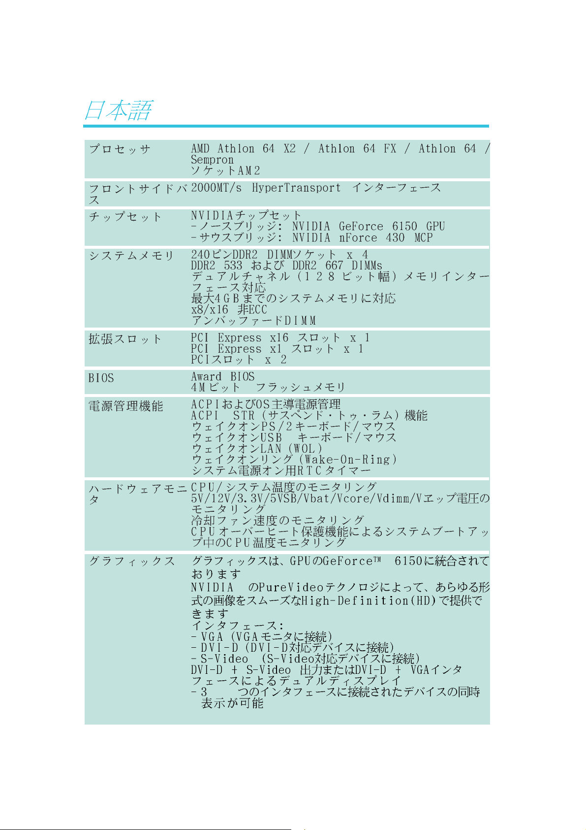
Specifications
Processor
HyperTransport
Chipset
System Memory
Expansion Slots
BIOS
Power Management
• AMD® AthlonTM 64 X2 / Athlon 64 FX / AthlonTM 64 /
Sempron
• Socket AM2
• 2000MT/s HyperTransport interface
• NVIDIA
- North bridge: NVIDIA® GeForceTM 6150 GPU
- South bridge: NVIDIA® nForceTM 430 MCP
• Four 240-pin DDR2 DIMM sockets
• Supports DDR2 533 and DDR2 667 DIMMs
• Supports dual channel (128-bit wide) memory interface
• Supports up to 4GB system memory
• Supports non-ECC x8 and x16 DIMMs
• Supports unbuffered DIMMs
• 1 PCI Express x16 slot
• 1 PCI Express x1 slot
• 2 PCI slots
• Award BIOS
• 4Mbit flash memory
• ACPI and OS Directed Power Management
• ACPI STR (Suspend to RAM) function
• Wake-On-PS/2 Keyboard/Mouse
• Wake-On-USB Keyboard/Mouse
• Wake-On-LAN
• Wake-On-Ring
• RTC timer to power-on the system
TM
®
chipset
Hardware Monitor
Graphics
• Monitors CPU/system temperature
•Monitors 5V/12V/3.3V/5VSB/Vbat/Vcore/Vdimm/Vchip
voltages
• Monitors the speed of the cooling fans
• CPU Overheat Protection function monitors CPU temperature
during system boot-up
TM
• Graphics integrated in the GeForce
• Includes NVIDIA® PureVideoTM technology that delivers smooth
High-Definition (HD) video in all formats and outstanding
picture clarity
•Interfaces:
- VGA to connect VGA monitor
- DVI-D to connect devices that support DVI-D
- S-Video to connect a TV with S-Video output
• Dual display using DVI-D + S-Video or DVI-D + VGA
interfaces
- devices connected to these interfaces can be displayed
simultaneously
6150 GPU
8
Page 9

Introduction
1
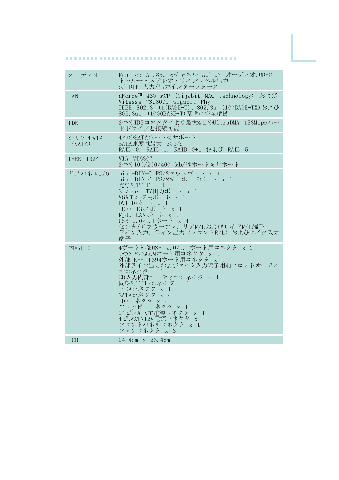
Audio
LAN
IDE
Serial ATA with
RAID
IEEE 1394
Rear Panel I/O
• Realtek ALC850 8-channel AC’97 audio CODEC
• True stereo line level outputs
• S/PDIF-in/out interface
TM
• nForce
cess Control) technology and external Vitesse VSC8601 Gigabit
Phy
• Fully compliant to IEEE 802.3 (10BASE-T), 802.3u (100BASETX) and 802.3ab (1000BASE-T) standards
• Supports two IDE connectors that allows connecting up to
four UltraDMA 133Mbps hard drives
• Supports four Serial ATA ports
• SATA speed up to 3Gb/s
• RAID 0, RAID 1, RAID 0+1 and RAID 5
• VIA VT6307
• Supports two 100/200/400 Mb/sec ports
• 1 mini-DIN-6 PS/2 mouse port
• 1 mini-DIN-6 PS/2 keyboard port
• 1 optical S/PDIF
• 1 S-Video TV-out port
• 1 VGA port
• 1 DVI-D port
• 1 IEEE 1394 port
• 1 RJ45 LAN port
• 4 USB 2.0/1.1 ports
• Center/subwoofer, rear R/L and side R/L jacks
• Line-in, line-out (front R/L) and mic-in jacks
430 MCP integrated with Gigabit MAC (Media Ac-
Internal I/O
PCB
• 2 connectors for 4 additional external USB 2.0/1.1 ports
• 1 connector for 1 external COM port
• 1 connector for 1 external IEEE 1394 port
• 1 front audio connector for external line-out and mic-in jacks
• 1 CD-in internal audio connector
• 1 coaxial S/PDIF connector
• 1 IrDA connector
• 4 Serial ATA connectors
• 2 IDE connectors
• 1 floppy connector
• 1 24-pin ATX main power connector
• 1 4-pin ATX 12V power connector
• 1 front panel connector
• 3 fan connectors
• 24.4cm (9.6") x 26.4cm (10.4")
9
Page 10

1
Introduction
Features
provides superior computing for many software applications by allowing both 32-bit and 64-bit applications to run simultaneously on
the same platform. The operating system and software are able to
process more data and access a tremendous amount of memory
which improves the overall system performance.
2T timing which provides better system stability is supported in CG
or later revisions of the AMD Athlon
the memory timing in the Genie BIOS Setting submenu (“DRAM
Timing and Config” section) of the BIOS.
The system board supports the AMD
Athlon
AthlonTM 64 / SempronTM processor
for Socket AM2. AMD Athlon
TM
64 X2 / Athlon 64 FX /
TM
TM
64 processor. You can select
64
The AMD Cool‘n’QuietTM technology allows
Cool‘n’Quiet
utilization status. When the CPU’s task slows down, the system effectively lowers power consumption by lowering its CPU speed and
voltage, subsequently decreasing its noise level.
multiple lanes. The system board currently supports the physical layer
of x1 and x16 lane widths. The x1 PCI Express lane supports transfer rate of 2.5 Gigabytes (250MBbps) per second. The PCI Express
architecture also provides a high performance graphics infrastructure
by enhancing the capability of a x16 PCI Express lane to provide 4
Gigabytes per second transfer rate.
TM
the system to detect the CPU’s tasks and
PCI Express is a high bandwidth I/O infrastructure
that possesses the ability to scale speeds by forming
10
Page 11
Introduction
The graphics integrated in the GeForceTM 6150 GPU
(Graphics Processing Unit) supports dual display by using either DVI-D + S-Video or DVI-D + VGA inter-
faces. The integrated HDTV Encoder provides TV-out
functionality up to 1080i resolution. It also supports Microsoft
DirectX® 9.0 Shader Model 3.0 and NVIDIA® PureVideoTM technology.
1
®
NVIDIA
high-definition video processors and video decoding
software that delivers HD (High-Definition) video to
your PC.
The DVI-D (Digital Visual Interface) port is used to
DVI
converts analog signals into digital signals. Data is transmitted using
the TMDS (Transition Minimized Differential Signaling) protocol, providing a digital signal from the PC’s graphics subsystem to the display.
S-Video
mitting video signals over a cable by dividing the video information
into two separate signals: color (chrominance) and brightness (luminance). These signals produce sharper images than composite video
where the video information is transmitted as a single signal over
one wire.
connect a digital LCD monitor. DVI is an interface that
The S-Video port is used to connect a TV that comes
with S-Video output. S-Video is a technology for trans-
®
PureVideoTM technology is a combination of
NVIDIA® ActiveArmorTM is built into the
chipset to enhance network security. It protects the system’s networking connection especially during large file
downloads. ActiveArmor is activated the minute you turn on the PC.
It performs a thorough inspection of the data packets that flow in and
out of your network connection and only allows good packets to pass
through the firewall. ActiveArmor performs network and security
processing in the chipset, leaving the CPU free for other important
application processing.
11
Page 12
1
Introduction
CPU
Overheat
Protection
ture limit pre-defined by the CPU, the system will automatically shutdown. This preventive measure has been added to protect the CPU
from damage and insure a safe computing environment.
DDR2 SDRAM modules work at 1.8V supply compared to 2.6V
memory voltage for DDR modules. DDR2 also incorporates new
innovations such as the On-Die Termination (ODT) as well as larger
4-bit pre-fetch against DDR which fetches 2 bits per clock cycle.
also supports S/PDIF input and output, allowing digital connections
with DVD systems or other audio/video multimedia.
CPU Overheat Protection has the capability of monitoring the CPU’s temperature during system boot up.
Once the CPU’s temperature exceeded the tempera-
DDR2 is a higher performance DDR technology whose
data transfer rate delivers bandwidth of 4.3 GB per second and beyond. That is twice the speed of the conventional DDR without increasing its power consumption.
The onboard Realtek ALC850 which is an AC’97 compatible audio codec and the 6 audio jacks at the rear I/
O panel provides 8-channel audio output for advanced
7.1-channel super surround sound audio system. ALC850
S/PDIF is a standard audio file transfer format that transfers digital audio signals to a device without having to be
converted first to an analog format. This prevents the
quality of the audio signal from degrading whenever it is
converted to analog. S/PDIF is usually found on digital audio equipment such as a DAT machine or audio processing device. The S/
PDIF connector on the system board sends surround sound and 3D
audio signal outputs to amplifiers and speakers and to digital recording devices like CD recorders.
Serial ATA is a storage interface that is compliant with
SATA 1.0 specification. nForce
Communications Processor) supports 4 Serial ATA ports
with speed of up to 3Gb/s. Serial ATA improves hard
drive performance faster than the standard parallel ATA whose data
transfer rate is 100MB/s. The system board supports RAID 0,
RAID 1, RAID 0+1 and RAID 5.
TM
430 MCP (Media and
12
Page 13
Introduction
The Gigabit MAC (Media Access Control) technology integrated in nForceTM 430 MCP and the external Vitesse
VSC8601 Gigabit Phy supports up to 1Gbps.
IEEE 1394 is fully compliant with the 1394 OHCI (Open
Host Controller Interface) 1.1 specification. It supports up
to 63 devices that can run simultaneously on a system.
1394 is a fast external bus standard that supports data
transfer rates of up to 400Mbps. In addition to its high speed, it
also supports isochronous data transfer which is ideal for video devices that need to transfer high levels of data in real-time. 1394
supports both Plug-and-Play and hot plugging.
1
IrDA
peripheral devices. The IRDA (Infrared Data Association) specification
supports data transfers of 115K baud at a distance of 1 meter.
speeds between your computer and a wide range of simultaneously
accessible external Plug and Play peripherals.
W ake-On-Ring
wake-up/power-on to respond to calls coming from an external modem or respond to calls from a modem PCI card that uses the PCI
PME (Power Management Event) signal to remotely wake up the
PC.
The system board is equipped with an IrDA connector
for wireless connectivity between your computer and
The system board supports USB 2.0 and USB 1.1
ports. USB 1.1 supports 12Mb/second bandwidth
while USB 2.0 supports 480Mb/second bandwidth
providing a marked improvement in device transfer
This feature allows the system that is in the
Suspend mode or Soft Power Off mode to
Important:
If you are using a modem add-in card, the 5VSB power source
of your power supply must support a minimum of ≥720mA.
13
Page 14
1
Introduction
W ake-On-LAN
It is supported via the onboard LAN port or via a PCI LAN card
that uses the PCI PME (Power Management Event) signal. However,
if your system is in the Suspend mode, you can power-on the system
only through an IRQ or DMA interrupt.
Important:
The 5VSB power source of your power supply must support
≥
720mA.
W ake-On-PS/2
tem.
Important:
The 5VSB power source of your power supply must support
≥
720mA.
This feature allows the network to remotely
wake up a Soft Power Down (Soft-Off) PC.
This function allows you to use the PS/2 keyboard or PS/2 mouse to power-on the sys-
W ake-On-USB
from the S3 (STR - Suspend To RAM) state.
Important:
If you are using the Wake-On-USB Keyboard/Mouse function for
2 USB ports, the 5VSB power source of your power supply
must support ≥1.5A. For 3 or more USB ports, the 5VSB
power source of your power supply must support ≥2A.
This function allows you to use a USB keyboard or USB mouse to wake up a system
14
Page 15

Introduction
1
ACPI
ACPI has energy saving features that enables PCs to implement
Power Management and Plug-and-Play with operating systems that
support OS Direct Power Management. Currently, only Windows
2000/XP supports the ACPI function. ACPI when enabled in the
Power Management Setup will allow you to use the Suspend to
RAM function.
With the Suspend to RAM function enabled, you can power-off the
system at once by pressing the power button or selecting “Standby”
when you shut down Windows
through the sometimes tiresome process of closing files, applications
and operating system. This is because the system is capable of storing all programs and data files during the entire operating session
into RAM (Random Access Memory) when it powers-off. The operating session will resume exactly where you left off the next time you
power-on the system.
The system board is designed to meet the ACPI (Advanced Configuration and Power Interface) specification.
®®
®
®®
2000/XP without having to go
®®
®
®®
Important:
The 5VSB power source of your power supply must support
≥
1A.
15
Page 16

1
Introduction
Français
Caractéristiques et Spécifications
Processeur
Chipset
Mémoire Système
Logements
d’Extension
BIOS
Gestion de Puissance
• AMD® AthlonTM 64 X2 / Athlon 64 FX / AthlonTM 64 /
Sempron
• Socket AM2
• Interface HyperTransport 2000MT/s
• NVIDIA
- Pont nord: NVIDIA® GeForceTM 6150 GPU
- Pont sud: NVIDIA® nForceTM 430 MCP
• 4 socles DIMM DDR2 240-pin
• Supporte DDR2 533 et DDR2 667 DIMMs
• Supporte l’interface de mémoire deux canaux (128-bit)
• Supporte jusqu’à 4 GB de mémoire système
• Supporte exclusivement les modules DIMM non-ECC x8 et x16
• Supporte les DIMM non-tamponnés
• 1 slot PCI Express x16
• 1 slot PCI Express x1
• 2 slots PCI
• Award BIOS
• Mémoire Flash 4Mbit
• ACPI et OS Directed Power Management
• ACPI STR (Suspend to RAM) fonction
• Réveil-Sur-PS/2 Clavier/Souris
• Réveil-Sur-USB Clavier/Souris
• Eveil Sonnerie
• Réveil Par Le Réseau
• Minuterie RTC pour allumer le système
TM
®
chipset
16
Fonctions de
Moniteur de
Matériel
Graphiques
• Gère l’alarme de température et de surchauffe de CPU/
système
• Gère l’alarme de voltage et d’échec de 5V/12V/3.3V/5VSB/
Vbat/Vcore/Vdimm/Vchip
• Gère la vitesse de ventilateur du ventilateur
• Protection du CPU - supporte la mise hors circuit automatique
en cas de surchauffage du système
TM
• La carte vidéo integrée sur la base de GeForce
• `Òechnologie NVIDIA
la vidéo de Haute Définition (HD) dans tous les formats
• Interfaces:
- VGA pour la connection du moniteur VGA
- DVI-D pour la connection des installations qui supportent DVI-D
- S-Video pour la connection du TV avec la sortie S-Video
• Ecran de visualisation binaire avec utilisation de DVI-D + la
S-Video ou DVI-D + VGA interfaces
- des installations connectées aux interfaces données peuvent
travailler simultanément
®
PureVideoTM assure la reproduction de
6150 GPU
Page 17

Introduction
1
Audio
LAN
IDE
Serial ATA avec
RAID
IEEE 1394
Panneau Arrière
• Realtek ALC850 8-canaux AC’97 audio CODEC
• Sorties de niveau de lignes stéréo vraies
• Interface entrée/sor tie S/PDIF
TM
• nForce
(Media Access Control) et extérieur Vitesse VSC8601 Gigabit
Phy
•Entièrement conforme IEEE 802.3 (10BASE-T), 802.3u
(100BASE-TX) et 802.3ab (1000BASE-T) standard
• Supporte des disques durs jusqu’à UltraDMA 133Mbps
• Supporte 4 interface Serial ATA
• SATA vitesse jusqu’à 3Gb/s
• RAID 0, RAID 1, RAID 0+1 et RAID 5
• VIA VT6307
• Supporte 2 100/200/400 Mb/sec ports
I/O
• 1 port souris PS/2
• 1 port clavier PS/2
• 1 port optique S/PDIF
• 1 port de S-Video
• 1 port de DB-15 VGA
• 1 port de DVI-D
• 1 port IEEE 1394
• 1 port RJ45 LAN
• 4 ports USB 2.0/1.1
• Center/subwoofer, rear R/L et side R/L prises audio
• Line-in, line-out (front R/L) et mic-in prises audio
430 MCP avec la technologie integrée Gigabit MAC
Interne I/O
PCB
2 connecteurs pour 4 ports USB 2.0 supplémentaires
•
• 1 connecteur pour 1 série
• 1 connecteur pour 1 IEEE 1394
• 1 connecteur audio de l’avant pour la sortie ligne/l’entrée micro
connecteur CD-in audio internes
•1
• 1 S/PDIF coaxial
• 1 connecteur IrDA
•4 connecteurs Serial ATA
• 2 connecteurs IDE
• 1 connecteur de FDD
• 1 connecteur d’alimentation ATX 24-pin
• 1 connecteur d’alimentation 12V ATX 4-pin
• 1 connecteur devant panneau
• 3 connecteurs de ventilateurs
• 24.4cm (9.6") x 26.4cm (10.4")
17
Page 18

1
Introduction
Deutsch
Leistungsmerkmale und Technische Daten
Prozessor
Chipset
Systemspeicher
Expansion Schlitz
BIOS
Energie
Management
• AMD® AthlonTM 64 X2 / Athlon 64 FX / AthlonTM 64 /
Sempron
• Socket AM2
• Interface HyperTransport 2000MT/s
• NVIDIA
- Nordbrücke: NVIDIA® GeForceTM 6150 GPU
- Südbrücke: NVIDIA® nForceTM 430 MCP
• 4 Sockel 240-pin DDR2 DIMM
• Unterhält DDR2 533 und DDR2 667 DIMMs
• Unterhält 128-bit – Speiher mit den zwei Kanälen
• Unterhält bis zum 4GB-Systemspeicher
• Unterhält nur non-ECC x8 und x16 DIMMs
• Unterhält DIMMs ohne Dämpfer
• 1 PCI Express x16-Einbauplätzen
• 1 PCI Express x1-Einbauplätzen
• 2 PCI-Einbauplätzen
• Award BIOS
• Flash-Speicher 4Mbit
• ACPI und OS Directed Power Management
• ACPI STR (Suspend to RAM) funktion
• Wecken bei Betätigung der PS/2 Tastatur/Maus
• Wecken bei USB-Tastatur/Maus
• Wecken bei Klingeln
• Wecken des Systems durch das Netzwerk
• RTC-Taktgeber zum Einschalten des Systems
TM
®
chipset
18
Kleinteilmonitor
Audio
•Überwachung der Temperatur des CPU/Systems sowie
Warnsignal bei Überhitzung
• Überwachung der Spannungen des 5V/12V/3.3V/5VSB/Vbat/
Vcore/Vdimm/Vchip
• Überwachung der Geschwindigkeit des Ventilators
• Prozessor-Shutz - Die Ausschaltung bei der Überhitzung – die
automatische Ausschaltung des Computers bei der Überhitzung
• Realtek ALC850 8-Kanal-AC’97-audio-CODEC
• Naturgetreue Stereo-Leitungspegel-Ausgabe
• S/PDIF-In/Aus-Schnittstelle
Page 19

Introduction
1
Grafik
LAN
IDE
Serial ATA mit RAID
• Integrierte Grafik in der GeForceTM 6150 GPU.
• Beinhaltet NVIDIA® PureVideoTM Technologie, die High-Definition
(HD) Video in allen Formaten sowie herausragende Bildqualität
liefert.
• Schnittstellen:
- VGA zum Anschluss eines VGA Bildschirms
- DVI-D zum Anschluss von DVI-D-fähigen Geräten
- S-Video zum Anschluss an ein Fernsehgerät mit S-Video Out-
put
• Dual Displays, die DVI-D + S-Video oder DVI-D + VGA
Schnittstellen verwenden
- Geräte, die an diese Schnittstellen angeschlossen werden,
können simultan angezeigt werden
TM
• nForce
Control) Technologie und externem Vitesse VSC8601 Gigabit
Phy
• Völlig gefällig zu IEEE 802.3 (10BASE-T), 802.3u (100BASETX) und 802.3ab (1000BASE-T) standards
• Unterstützung der Festplatten bis zum UltraDMA 133Mbps
• Unterstützt 4 Serial ATA-porte
• 3Gb/s SATA-Geschwindigkeit
• RAID 0, RAID 1, RAID 0+1 und RAID 5
430 MCP integriert mit Gigabit MAC (Media Access
IEEE 1394
Porte an der
Rückwand
Internes I/O
• VIA VT6307
• Unterstützt 2 100/200/400 Mb/sec porte
• 1 Mini-DIN-6-Anschluß für eine PS/2-Maus
• 1 Mini-DIN-6-Anschluß für eine PS/2-Tastatur
• 1 S/PDIF optischen-Anschlüsse
• 1 S-Video-Anschlüsse
• 1 VGA DB-15-Anschlüsse
• 1 DVI-D-Anschlüsse
• 1 IEEE 1394-Anschlüsse
• 1 RJ45 LAN-Anschlüsse
• 4 USB 2.0/1.1-Anschlüsse
• Center/subwoofer, rear R/L und side R/LAudio-Anschlußbuchsen
• Line-in, line-out (front R/L) und mic-in Audio-Anschlußbuchsen
• 2 Anschlußfassung für 4 zusätzliche externe USB 2.0-Anschlüsse
• 1 Anschluß für eine externe serieller Schnittstelle
• 1 Anschluß für eine externe IEEE 1394 Schnittstelle
• 1 Frontaudioanschluß für die externe Ausgangsleitung und den
Mikrofoneingang
• 1 interne Audioanschlüsse (CD-in)
• 1 coaxial S/PDIF-Anschluß und 1 IrDA-Anschluß
• 4 Serial-ATA-Anschlüsse
• 2 IDE-Anschlüsse und 1 Floppy-Anschlüsse
• 1 Anschlußstecker für das ATX-Netzgerät 24-pin
• 1 Anschlußstecker für das 12V ATX-Netzgerät 4-pin
• 1 Frontabdeckung Stecker und 3-ventilator-Anschlüsse
PCB
• 24.4cm (9.6") x 26.4cm (10.4")
19
Page 20

1
Introduction
Español
Características y Especificaciones
Procesador
Chipset
Memoria de Sistema
Ranuras de
Expansión
BIOS
Gerencia de la
Energía
• AMD® AthlonTM 64 X2 / Athlon 64 FX / AthlonTM 64 /
Sempron
• Socket AM2
• Interface de HyperTransport 2000MT/s
• NVIDIA
- Puente norte: NVIDIA® GeForceTM 6150 GPU
- Puente sur: NVIDIA® nForceTM 430 MCP
• 4 240-pin DDR2 DIMM asientos
• Suporta DDR2 533 y DDR2 667 DIMMs
• Soporta memoria de dos canales (128-bit)
• Soporta hasta 4GB de memoria sistémica
• Soporta sólo non-ECC x8 y x16 DIMM
• Soporta unbuffered DIMM
• 1 slot PCI Express x16
• 1 slot PCI Express x1
• 2 slots PCI
• Award BIOS
• Memoria instante 4Mbit
• ACPI y OS Directed Power Management
• ACPI STR (Suspend to RAM) función
• PS/2 Teclado/Ratón de Wake-On
• USB Teclado/Ratón de Wake-On
• Wake-On-Ring
• Wake-On-LAN
• Temporizador de RTC para encender el sistema
TM
®
chipset
20
Monitor del
Hardware
Audio
•Monitores de los CPU/sistema temperaturas y alarma
acalorada.
• Monitores de voltajes de 5V/12V/3.3V/5VSB/Vbat/Vcore/
Vdimm/Vchip
• Vigila la velocidad del abanico del abanido
• Protección del procesador - Desconección en caso de
recalentamiento –el ordenador se desconecta automáticamente
en caso de recalentamiento
• Realtek ALC850 8-canal AC’97 audio CODEC
• Auténtico salidas de nivel de línea estéreo
• Interfáz de S/PDIF-in/out
Page 21

Introduction
1
Gráficos
LAN
IDE
Serial ATA con
RAID
IEEE 1394
• Gráficos integrados en la GPU GeForceTM 6150
• Incluye la tecnología PureVideo
reproducción optimizada de vídeo en Alta Definición (HD) en
cualquier formato y una excepcional nitidez de imagen
• Interfaces:
- VGA para la conexión de un monitor VGA
- DVI-D para la conexión de monitores compatibles DVI-D
- S-Video para la conexión a una TV con conector S-Video
• Pantalla dual: conexión DVI-D + S-Video o DVI-D + VGA
- los dispositivos conectados a estos interfaces pueden ser
visualizados de forma simultánea
TM
• nForce
(Media Access Control) y Vitesse VSC8601 Gigabit Phy
externo
• Completamente a IEEE 802.3 (10BASE-T), 802.3u (100BASETX) y 802.3ab (1000BASE-T) estándar
• Soporta las unidades duras hasta de UltraDMA 133Mbps
• Soporta 4 interfaz Serial ATA
• Velocidad de SATA a 3Gb/s
• RAID 0, RAID 1, RAID 0+1 y RAID 5
• VIA VT6307
• Soporta 2 ports 100/200/400 Mb/sec
430 MCP integrado con la tecnología Gigabit MAC
TM
de NVIDIA®, que permite la
Panel Trasero I/O
Conectador Interno
• 1 puerto de ratón mini-DIN-6 PS/2
• 1 puerto de teclado mini-DIN-6 PS/2
• 1 puerto de S/PDIF óptico
• 1 puerto de S-Video
• 1 puerto de VGA DB-15
• 1 puerto de DVI-D
• 1 puerto de IEEE 1394
• 1 puerto de RJ45 LAN
• 4 puertos de USB 2.0/1.1
• Center/subwoofer, rear R/L y side R/L enchufes de audio
• Line-in, line-out (front R/L) y mic-in enchufes de audio
• 2 conectors para 4 puertos de USB 2.0/1.1 externo adicional
• 1 conector para un puerto de serie
• 1 conector para un puerto de IEEE 1394
• 1 conectador audio delantero para la salida extrema de linea
y el micro
• 1 conector de CD-in audio interno
• 1 S/PDIF coaxial
• 1 conector de IrDA
• 4 conectores de Serial ATA
• 2 conector de IDE y 1 conector de FDD
• 1 conectore de 24-pin fuente de alimentación de ATX
• 1 conectore de 12V 4-pin fuente de alimentación de ATX
• 1 conector de conectador del panel delantero
• 3 conectores de abanicos
PCB
• 24.4cm (9.6") x 26.4cm (10.4")
21
Page 22

1
Introduction
Русский языкРусский язык
Русский язык
Русский языкРусский язык
Характеристики и свойстваХарактеристики и свойства
Характеристики и свойства
Характеристики и свойстваХарактеристики и свойства
ПроцессорПроцессор
Процессор
ПроцессорПроцессор
ЧипсетЧипсет
Чипсет
ЧипсетЧипсет
ОперативнаяОперативная
Оперативная
ОперативнаяОперативная
ПамятьПамять
Память
ПамятьПамять
• AMD® AthlonTM 64 X2 / Athlon 64 FX / AthlonTM 64 /
Sempron
• гнездо AM2
• Интерфейс системной шины 2000MT/s
• NVIDIA
- Северный мост: NVIDIA® GeForceTM 6150 GPU
- Южный мост: NVIDIA® nForceTM 430 MCP
•4 240-pin DDR2 DIMM гнезда
•Поддерживает DDR2 533 и DDR2 667 DIMMs
•Поддерживает двухканальную память (128-бит)
•Поддерживает до 4ГБ системной памяти
•Поддерживает только non-ECC x8 и x16 DIMM
•Поддерживает небуфф. DIMM
TM
®
Чипсет
управлениеуправление
управление
управлениеуправление
силыñèëû
ñèëû
ñèëûñèëû
BIOSBIOS
BIOS
BIOSBIOS
управлениеуправление
управление
управлениеуправление
силыñèëû
ñèëû
ñèëûñèëû
монитормонитор
монитор
монитормонитор
оборудованияоборудования
оборудования
оборудованияоборудования
тональнозвуковотональнозвуково
тональнозвуково
тональнозвуковотональнозвуково
•1 PCI Express x16 слотов
•1 PCI Express x1 слотов
•2 PCI слотов
•Award BIOS
• 4Mbit внезапная память
•ACPI è OS Directed Power Management
•ACPI STR (Suspend to RAM)
•Активизация На Движение Мыши
•Активизация На Нажатие Кнопки USB Клавиатуры
•Активизация На Входящий Звонок
•Активизация На Сетевое Событие
•RTC Таймер для Включения Системы
•Mониторинг температуры процессора/системы
•Mониторинг напряжений 5V/12V/3.3V/5VSB/Vbat/
Vcore/Vdimm/Vchip
•Mониторинг скорости вращения вентилятора
•Защита процессора - Выключение при перегреве –
автоматическое выключение компьютера при
перегреве
•Realtek ALC850 8-канал AC’97 CODEC
•Настоящий линейный стерео выход
•интерфейса S/PDIF-in и S/PDIF-out
22
Page 23

ГрафикаГрафика
Графика
ГрафикаГрафика
LANLAN
LAN
LANLAN
Introduction
• Встроенная видеокарта на базе GeForceTM 6150
•Технология NVIDIA® PureVideoTM, обеспечивающая
воспроизведение Высококачественного Видео (HD) во
всех форматах
• Интерфейсы:
- VGA для подключения VGA монитора
- DVI-D для подключения устройств DVI-D
- S-Video для подключения телевизоров с S-Video
выходом
•Двойной экран с использованием DVI-D + S-Video или
DVI-D + VGA интерфейсов
- устройства, подключенные к данным интерфейсам
могут работать одновременно
TM
•nForce
MAC (Media Access Control) и внешним Vitesse
VSC8601 Gigabit Phy
•Поддерживает IEEE 802.3 (10BASE-T), 802.3u
(100BASE-TX) и 802.3ab (1000BASE-T)
430 MCP со встроенной технологией Gigabit
1
IDEIDE
IDE
IDEIDE
Serial ASerial A
Serial A
Serial ASerial A
RAIDRAID
RAID
RAIDRAID
IEEE 1394IEEE 1394
IEEE 1394
IEEE 1394IEEE 1394
задняя панельзадняя панель
задняя панель
задняя панельзадняя панель
I/OI/O
I/O
I/OI/O
внутренне внутренне
внутренне
внутренне внутренне
TT
A cA c
T
A c
TT
A cA c
I/OI/O
I/O
I/OI/O
•Поддерживает жесткие диски до UltraDMA 133Mbps
•Поддерживает 4 Serial ATA порта
•SATA скорость up к 3Gb/s
•RAID 0, RAID 1, RAID 0+1 è RAID 5
•VIA VT6307
•Поддерживает 2 100/200/400 Mb/sec порта
•1 ìèíè-DIN-6 PS/2 ïîðò äëÿ ìûøè
•1 мини-DIN-6 PS/2 порт для клавиатуры
•1 S/PDIF оптического порт
•1 S-Video порта и 1 VGA порта
•1 DVI-D порта
•1 IEEE 1394 ïîðò
•1 RJ45 LAN порт и 4 USB 2.0/1.1 порта
•Center/subwoofer, rear R/L и side R/L гнезда для звука
•Mic-in, line-in и line-out гнезда для звука
•2 разъем для 4-х дополнительных внешних USB 2.0
портов
•1 разъем для внешнего внешнего порта
•1 разъем для внешнего IEEE 1394 порта
•1 передний аудио разъем для внешнего линейного
выхода и микрофона
•1 внутренних звуковых разъема (CD-in)
•1 coaxial S/PDIF разъем
•1 разъем для интерфейса IrDA
•4 Serial ATA, 2 IDE разъема и 1 разъем FDD
•1 разъема питания ATX 24-pin
•1 разъема питания 12V ATX 4-pin
•1 Фронт панель разъем
•3 Разъемы для вентилятора
PCBPCB
PCB
PCBPCB
•24.4cm (9.6") x 26.4cm (10.4")
23
Page 24
1
Introduction
24
Page 25
Introduction
1
25
Page 26
2
Hardware Installation
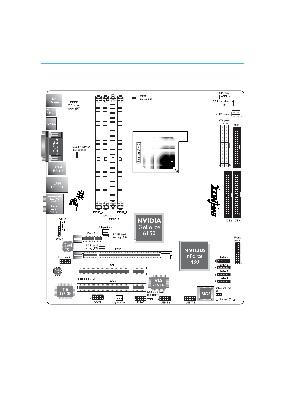
Chapter 2 - Hardware Installation
System Board Layout
26
Page 27
Warning:
.
.
.
.
.
.
.
.
.
.
.
.
.
.
.
.
Electrostatic discharge (ESD) can damage your system board,
processor, disk drives, add-in boards, and other components. Perform
the upgrade instruction procedures described at an ESD workstation
only. If such a station is not available, you can provide some ESD
protection by wearing an antistatic wrist strap and attaching it to a
metal part of the system chassis. If a wrist strap is unavailable,
establish and maintain contact with the system chassis throughout
any procedures requiring ESD protection.
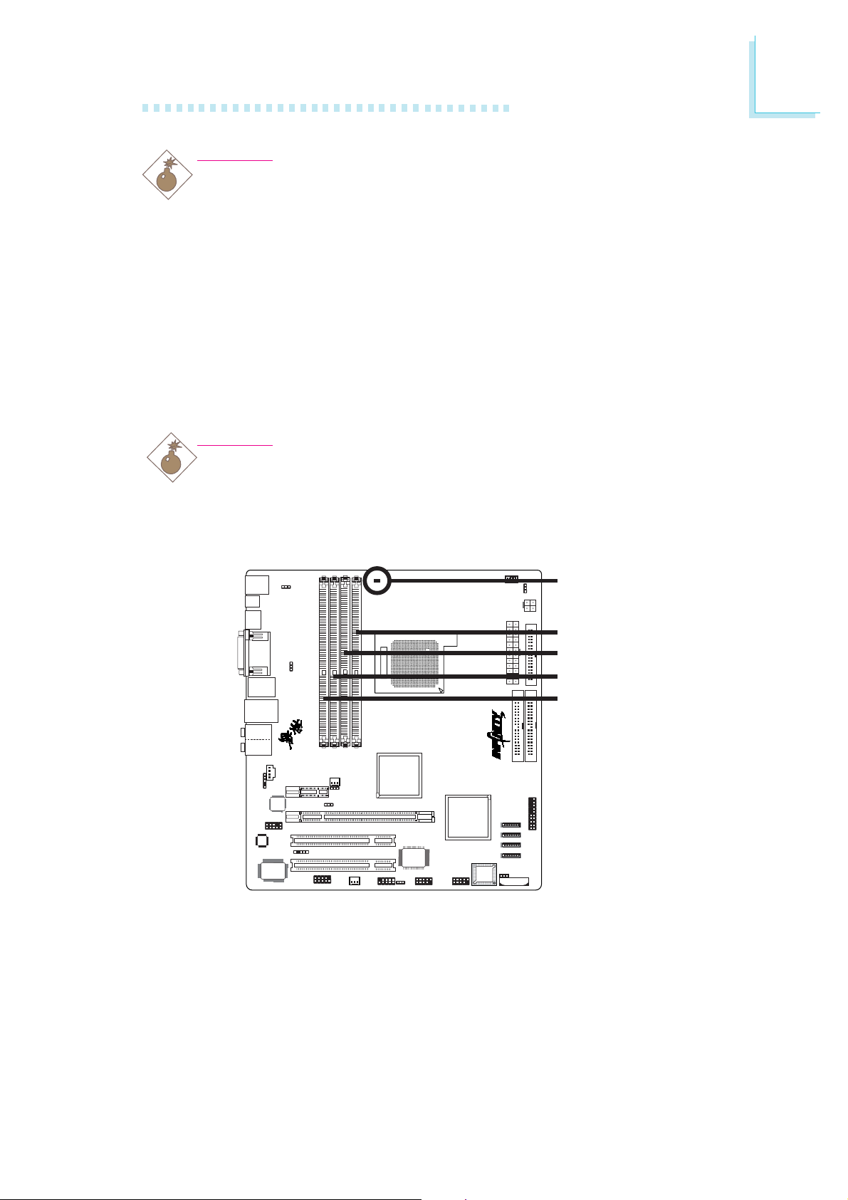
System Memory
Warning:
When the DRAM Power LED lit red, it indicates that power is
present on the DDR2 sockets. Power-off the PC then unplug the
power cord prior to installing any memory modules. Failure to do so
will cause severe damage to the motherboard and components.
Hardware Installation
2
DRAM Power LED
DDR2_1, Channel A
DDR2_2, Channel B
DDR2_3, Channel A
DDR2_4, Channel B
The system board supports 240-pin DDR2 DIMM sockets. The four
DDR2 DIMM sockets on the system board are divided into 2 channels:
Channel A - DDR2_1 and DDR2_3
Channel B - DDR2_2 and DDR2_4
27
Page 28

2
Hardware Installation
The system board supports the following memory interface.
Single Channel (SC)
Data will be accessed in chunks of 64 bits (8B) from the memory
channels.
Dual Channel (DC)
Data will be accessed in chunks of 128 bits from the memory
channels. Dual channel provides better system performance because
it doubles the data transfer rate.
Single Channel
Dual Channel
The table below shows the DIMM sockets that must be populated
with DIMMs for single or dual channel interface. We strongly
recommend that you strictly follow the memory configurations below.
Installing DDR2 DIMMs other than the recommended configurations
may cause system boot failure.
Dual Channel
Dual Channel
• DIMMs are on the same channel.
• DIMMs in a channel can be identical or
completely different. However, we highly
recommend using identical DIMMs.
• Not all slots need to be populated.
• DIMMs of the same memory configura-
tion are on different channels.
DDR2-1
-
DDR2-2
-
-
DDR2-3
-
DDR2-4
28
Dual Channel
Single Channel
Single Channel
Single Channel
Single Channel
BIOS Setting
Configure the system memory in the Genie BIOS Setting submenu
(“DRAM Configuration” section) of the BIOS.
DDR2-1
DDR2-1
-
DDR2-1
-
DDR2-2
-
-
-
DDR2-2
DDR2-3
DDR2-3
DDR2-3
-
DDR2-4
-
-
-
DDR2-4
Page 29
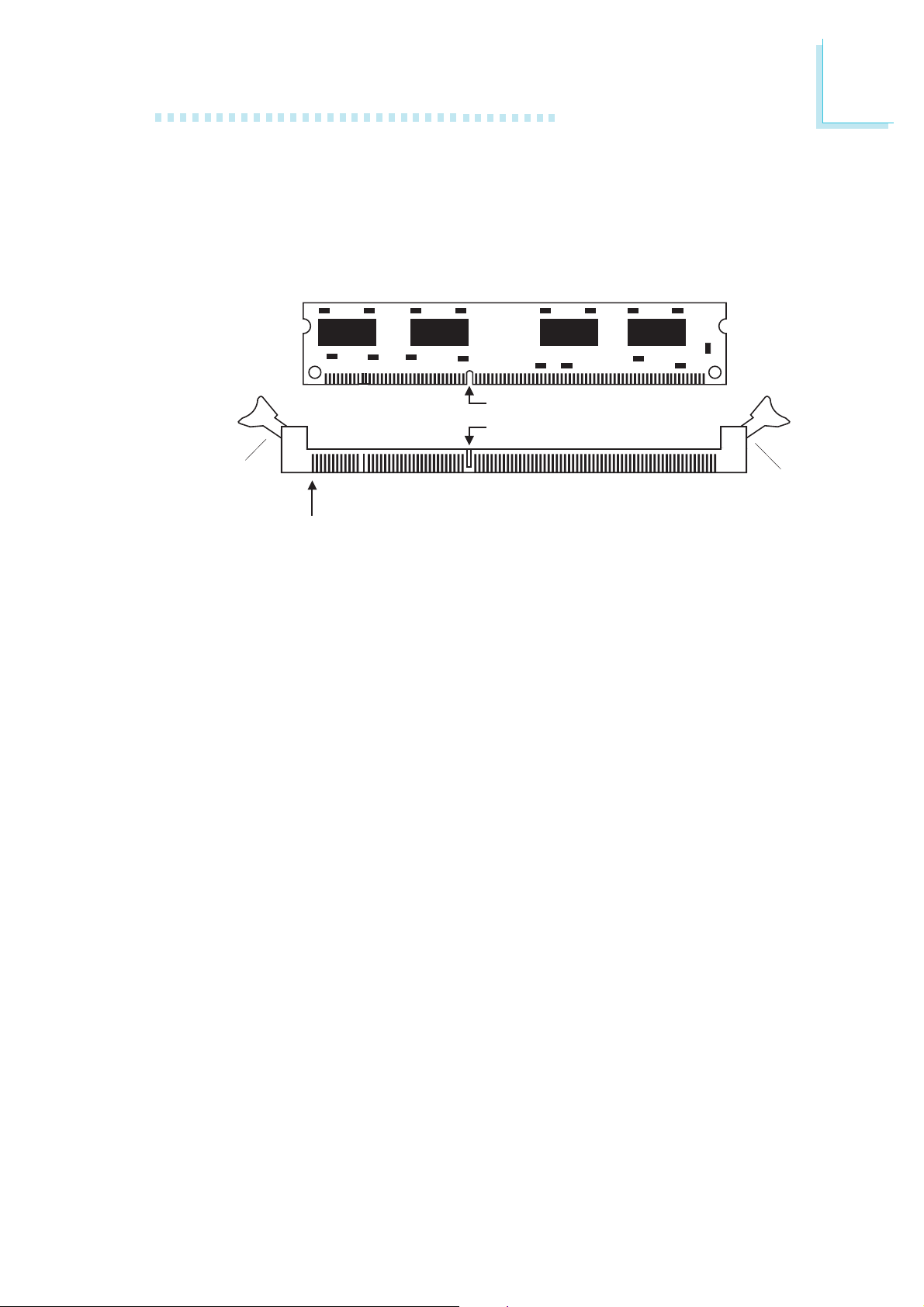
Installing the DIM Module
A DIM module simply snaps into a DIMM socket on the system
board. Pin 1 of the DIM module must correspond with Pin 1 of the
socket.
Hardware Installation
2
Notch
Key
Tab
Pin 1
1. Pull the “tabs” which are at the ends of the socket to the side.
2. Position the DIMM above the socket with the “notch” in the
module aligned with the “key” on the socket.
3. Seat the module vertically into the socket. Make sure it is
completely seated. The tabs will hold the DIMM in place.
Tab
29
Page 30
2
Hardware Installation
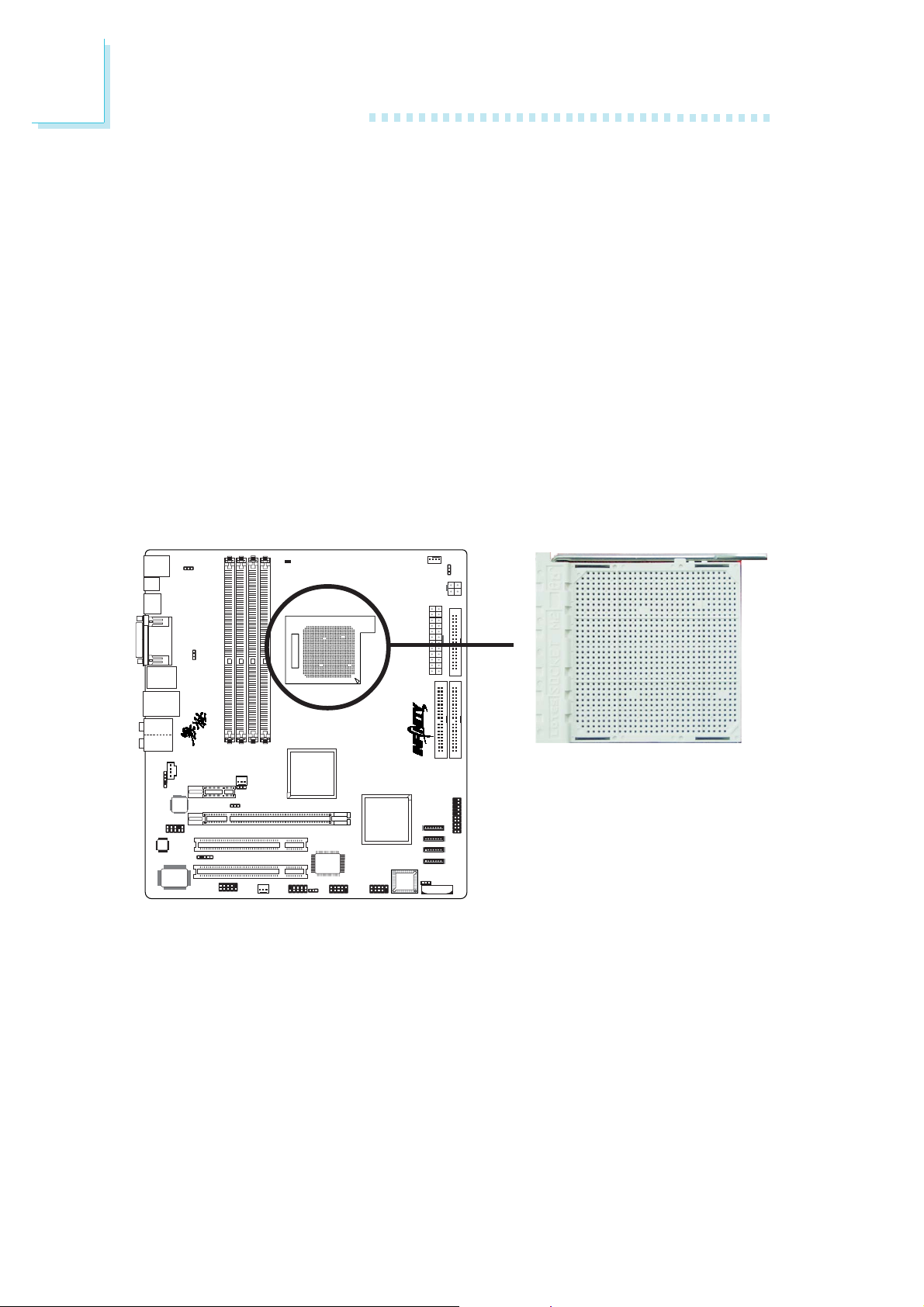
CPU
Overview
The system board is equipped with Socket AM2 for installing an
AMD CPU designed for this socket.
Installing the CPU
1. Make sure the PC and all other peripheral devices connected to
it has been powered down.
2. Disconnect all power cords and cables.
3. Locate Socket AM2 on the system board.
X
30
Page 31

Hardware Installation
4. Unlock the socket by pushing the lever sideways, away from the
socket, then lifting it up to a 90
to at least this angle otherwise the CPU will not fit in properly.
Lever
o
angle. Make sure the lever is lifted
2
5. Position the CPU above the socket. The gold mark on the CPU
must align with the corner of the CPU socket (refer to the
enlarged image) shown below.
Important:
Handle the CPU by its edges and avoid touching the pins.
Gold mark
31
Page 32

2
Hardware Installation
6. Insert the CPU into the socket until it is seated in place. The
CPU will fit in only one orientation and can easily be inserted
without exerting any force.
Important:
Do not force the CPU into the socket. Forcing the CPU into
the socket may bend the pins and damage the CPU.
7. Once the CPU is in place, push down the lever to lock the
socket. The lever should click on the side tab to indicate that the
CPU is completely secured in the socket.
Side tab
32
Page 33

Installing the Fan and Heat Sink
The CPU must be kept cool by using a CPU fan with heat sink.
Without sufficient air circulation across the CPU and heat sink, the
CPU will overheat damaging both the CPU and system board.
The fan / heat sink assembly must provide airflow adequate to
ensure appropriate internal temperature and cooling of the
components in the system. Failure to use the appropriate cooling
system may result in reduced performance or, in some instances,
damage to the system board.
Note:
• Use only certified fan and heat sink.
• The fan and heat sink package usually contains the fan and
heat sink assembly, and an installation guide. If the
installation procedure in the installation guide differs from
the one in this section, please follow the installation guide in
the package.
Hardware Installation
2
1. Before you install the fan / heat sink, you must apply a thermal
paste onto the top of the CPU. The thermal paste is usually
supplied when you purchase the CPU or fan heat sink assembly.
Do not spread the paste all over the surface. When you later
place the heat sink on top of the CPU, the compound will
disperse evenly.
Do not apply the paste if the fan / heat sink already has a patch
of thermal paste on its underside. Peel the strip that covers the
paste before you place the fan / heat sink on top of the CPU.
2. The system board comes with the retention module base already
installed.
Retention
module base
33
Page 34

2
Hardware Installation
3. Place the heat sink on top of the CPU. Now hook one side of
the retention clip onto the retention module base by fitting the
holes on the retention clip into the retaining tabs of the retention
module base.
Retaining
tab
Retention clip
Retention module base
Side View
Retaining
tabs
Retaining
tabs
Top View
34
Page 35

Hardware Installation
4. Hook the other side of the retention clip (the one near the
retention lever) so that the holes on the retention clip also fit
into the retaining tabs of the retention module base.
Note:
You will not be able to secure the fan and heat sink
assembly in place if it did not fit properly onto the
retention module base.
Retention lever
2
5. Move the retention lever to its opposite side then push it down
to lock the fan and heat sink assembly to the retention module
base.
Note:
Make sure there is sufficient air circulation across the CPU
fan and heat sink.
6. Connect the CPU fan’s cable connector to the CPU fan connector on the system board.
35
Page 36

2
Hardware Installation
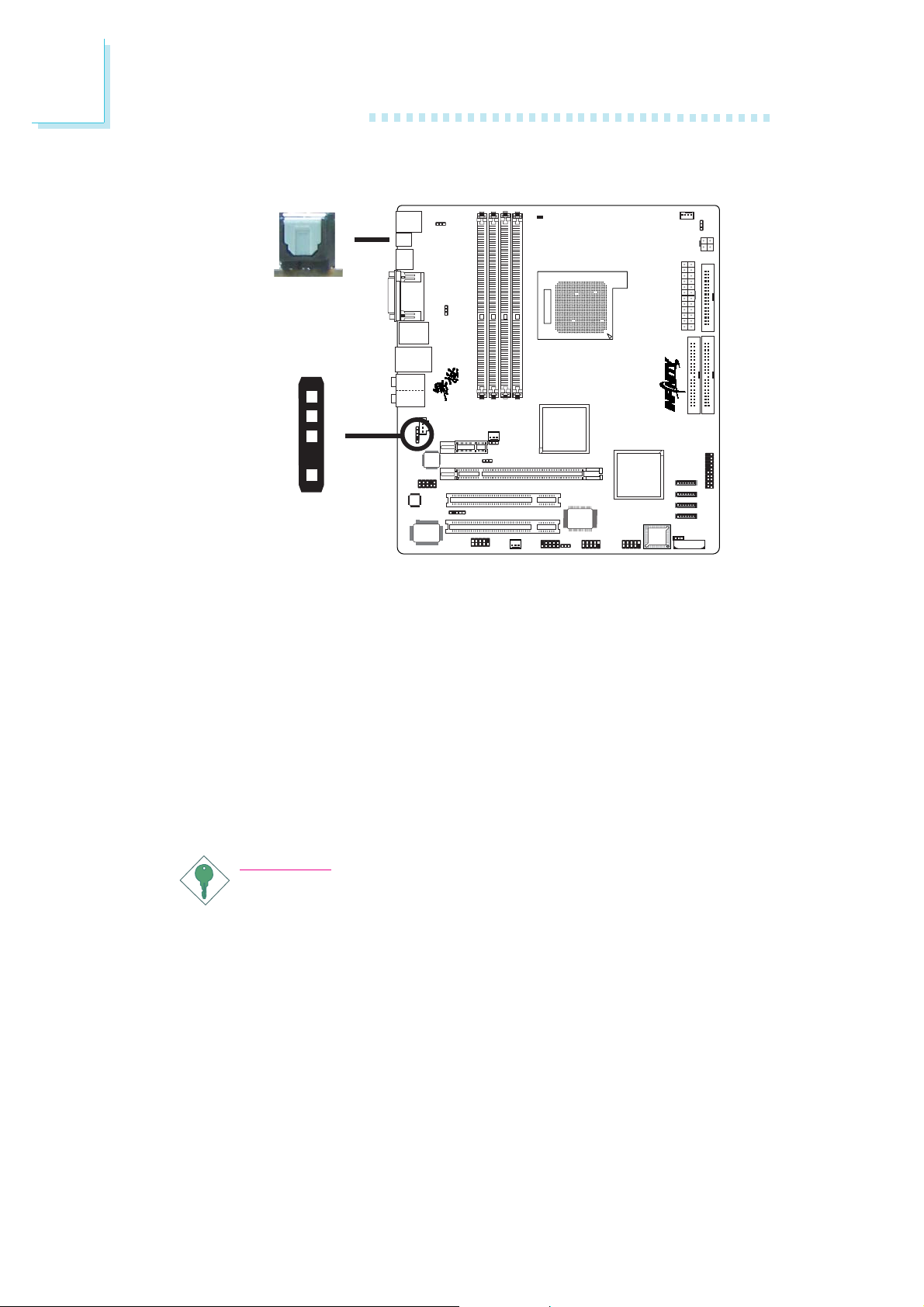
Jumper Settings
Clear CMOS Data
312
1-2 On: Normal
(default)
312
JP1
X
If you encounter the following,
a) CMOS data becomes corrupted.
b) You forgot the supervisor or user password.
c) You are unable to boot-up the computer system because the
processor’s ratio/clock was incorrectly set in the BIOS.
you can reconfigure the system with the default values stored in the
ROM BIOS.
To load the default values stored in the ROM BIOS, please follow
the steps below.
1. Power-off the system then unplug the power cord.
2. Set JP1 pins 2 and 3 to On. Wait for a few seconds and set JP1
back to its default setting, pins 1 and 2 On.
2-3 On:
Clear CMOS Data
36
3. Now plug the power cord then power-on the system.
If your reason for clearing the CMOS data is due to incorrect
setting of the processor’s ratio/clock in the BIOS, please proceed
to step 4.
Page 37

Hardware Installation
4. After powering-on the system, press <Del> to enter the main
menu of the BIOS.
5. Select the Genie BIOS Setting submenu and press <Enter>.
6. Set the processor’s clock/ratio to its default setting or an appropriate bus clock or ratio. Refer to the Genie BIOS Setting section
in chapter 3 for more information.
7. Press <Esc> to return to the main menu of the BIOS setup
utility. Select “Save & Exit Setup” and press <Enter>.
8. Type <Y> and press <Enter>.
2
37
Page 38

2
Hardware Installation
PS/2 Power Select
JP7
132
132
X
2-3 On: 5VSB1-2 On: 5V
(default)
JP7 is used to select the power of the PS/2 keyboard/mouse port.
Selecting 5VSB will allow you to use the PS/2 keyboard or PS/2
mouse to wake up the system.
BIOS Setting
Configure the PS/2 keyboard/mouse wake up function in the Power
Management Setup submenu of the BIOS. Refer to chapter 3 for
more information.
Important:
The 5VSB power source of your power supply must support
≥
720mA.
38
Page 39

USB Power Select
Hardware Installation
2
USB 1-4
(JP3)
X
1-2 On: 5V
USB 5-8
(JP4)
X
1
2
3
(default)
(default)
1
2
3
2-3 On: 5VSB
132
2-3 On: 5VSB1-2 On: 5V
132
JP3 and JP4 are used to select the power of the USB ports.
Selecting 5VSB will allow you to use the USB keyboard or USB
mouse to wake up the system.
Important:
If you are using the Wake-On-USB Keyboard/Mouse function for
2 USB ports, the 5VSB power source of your power supply
must support ≥1.5A. For 3 or more USB ports, the 5VSB
power source of your power supply must support ≥2A.
39
Page 40

2
Hardware Installation
PCI Express Card Setting
PCIE 2
PCIE 1
JP5
X
1-2 On:
Default
312 312
2-3 On:
To detect PCIE
card on PCIE 2 slot
JP6
312 312
X
1-2 On:
Default
The system can detect most PCI Express cards. However if you are
using cards such as Gigabyte GC-LC05 (BroadCom BCM5721) or
other cards not detected by the system, set JP5 and/or JP6 to 2-3
On. Configuring the jumper to 2-3 On will allow the system to
detect the PCI Express card.
JP5 is used to detect the PCI Express card installed in the PCIE 2
slot.
JP6 is used to detect the PCI Express card installed in the PCIE 1
slot.
2-3 On:
To detect PCIE
card on PCIE 1 slot
40
Page 41

CPU Fan Select
Hardware Installation
2
JP11
X
1-2 On:
3-pin CPU fan
3
2
1
4-pin CPU fan
3
2
1
2-3 On:
The system board allows connecting a CPU fan that comes with a
3-pin or 4-pin cable connector. Set JP11 according to the type of
cable connector that you are using.
Important:
If JP11 is set incorrectly, the system will not be able to appropriately detect the CPU fan.
41
Page 42

2
Hardware Installation
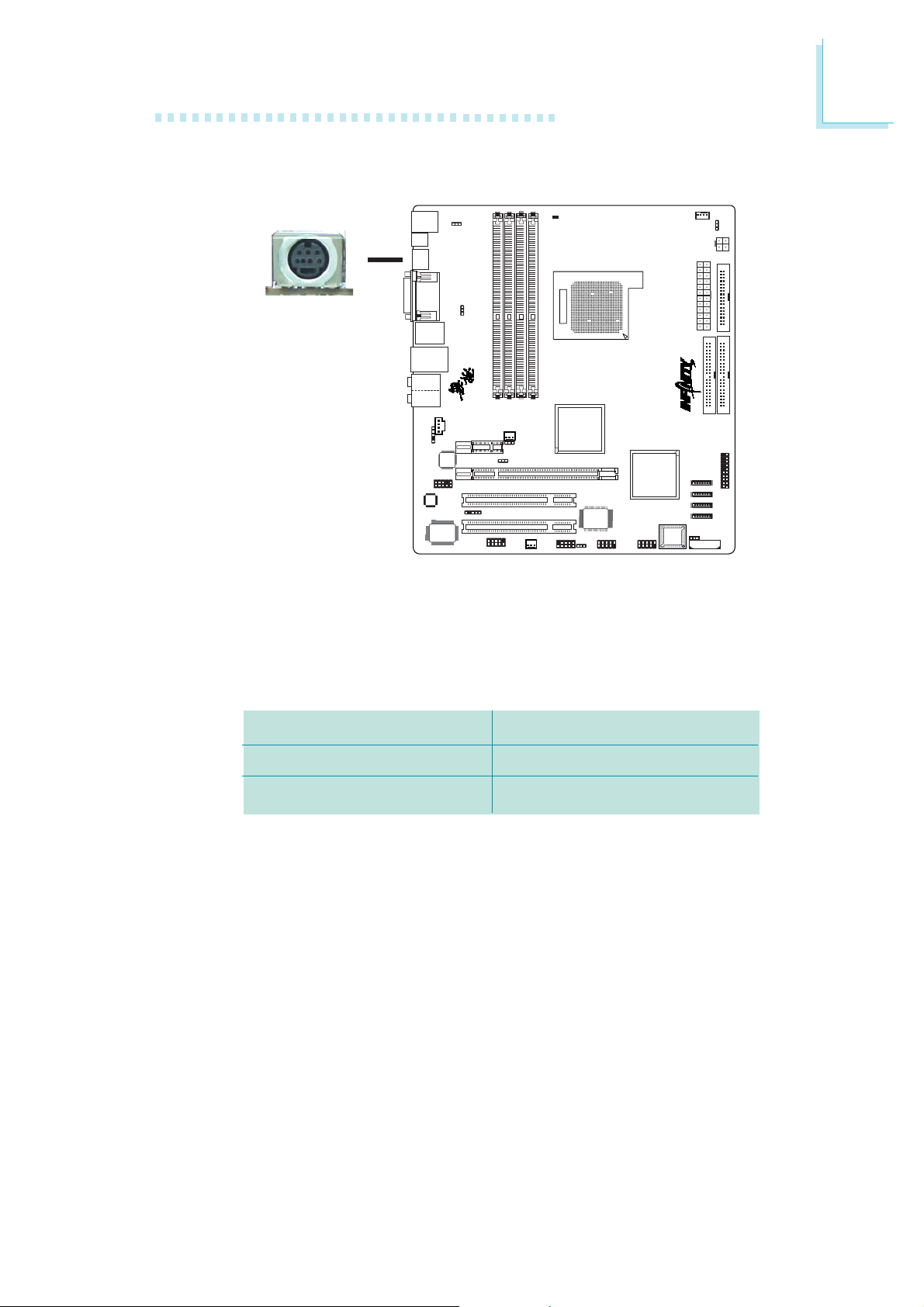
Rear Panel I/O Ports
PS/2
Mouse
VGA
IEEE
1394_1
Center/
Subwoofer
Rear R/L
LAN
Line-in
Front R/L
Mic-in
PS/2 K/B
S-Video
Optical
S/PDIF
DVI-D USB 1-2 USB 3-4
The rear panel I/O ports consist of the following:
• PS/2 mouse port
• PS/2 keyboard port
• Optical S/PDIF port
• S-Video port
• VGA monitor port
• DVI-D port
• IEEE 1394_1 port
• USB ports
• LAN port
• Center/Subwoofer port
• Rear R/L port
• Side R/L port
• Line-in port
• Front R/L port
• Mic-in port
Side R/L
42
Page 43

PS/2 Mouse and PS/2 Keyboard
Hardware Installation
2
PS/2 Mouse
PS/2 Keyboard
W
The system board is equipped with an onboard PS/2 mouse
(Green) and PS/2 keyboard (Purple) ports - both at location CN14
of the system board. The PS/2 mouse port uses IRQ12. If a mouse
is not connected to this port, the system will reserve IRQ12 for
other expansion cards.
.
.
.
.
Warning:
.
.
.
.
Make sure to turn off your computer prior to connecting or
disconnecting a mouse or keyboard. Failure to do so may
damage the system board.
Wake-On-PS/2 Keyboard/Mouse
The Wake-On-PS/2 Keyboard/Mouse function allows you to use the
PS/2 keyboard or PS/2 mouse to power-on the system. To use this
function:
• Jumper Setting:
JP7 must be set to “2-3 On: 5VSB”. Refer to “PS/2 Power
Select” in this chapter for more information.
• BIOS Setting:
Configure the PS/2 wake up function in the Power Management
Setup submenu of the BIOS. Refer to chapter 3 for more
information.
43
Page 44
2
Hardware Installation
S/PDIF
W
Optical S/PDIF-out
SPDIF in
GND
SPDIF out
Key
+5V
Coaxial RCA
S/PDIF-in/out
The system board is equipped with an onboard optical S/PDIF-out
port at location CN17. It is also equipped with a connector at
location J13 for coaxial RCA S/PDIF-in/out port connection. S/PDIF
ports are used to connect audio output devices.
Your coaxial RCA S/PDIF ports may come mounted on a card-edge
bracket. Install the card-edge bracket to an available slot at the rear
of the system chassis then connect the audio cable connector to J13.
Make sure pin 1 of the audio cable connector is aligned with pin 1
of J13.
5
W
1
44
Important:
DO NOT use optical S/PDIF and coaxial RCA S/PDIF at the
same time.
Page 45
S-Video
Hardware Installation
2
W
The S-Video port at location CN4 is used to connect a TV that
comes with an S-Video output or Composite video output. The
table below lists the supported video output and their corresponding cables.
TV-Out Port of TV
S-Video Output
Composite Video Output
Standard 4-pin S-Video cable
“S-Video to Composite TV” cable
Cables
45
Page 46

2
Hardware Installation
Video Output Cables
Standard 4-pin S-Video Cable for TV with S-Video In Port
Connect to 4-pin
S-Video port of TV
“S-Video to Composite TV” Cable (included in the package)
Connect to S-Video
port of system board
Connect to the AV
port of TV
.
.
.
.
Warning:
.
.
.
.
Connect to S-Video
port of system board
The “S-Video to Composite TV” cable is a customized cable
exclusively designed for use with this system board. Damage
may occur if you use a cable other than the one specified
above.
Dual Display
Aside from connecting a TV to the S-Video port, the system board
supports dual display by connecting another display device to the
DVI-D port.
Port
S-Video
and
DVI-D
Display Device
W
TV
and
W
LCD monitor or LCD TV
46
BIOS Setting
Configure the display devices in the Advanced Chipset Features
submenu of the BIOS. Refer to chapter 3 for more information.
Page 47

VGA
Hardware Installation
2
VGA
W
The VGA port is used for connecting a CRT VGA monitor. Connect
the monitor’s 15-pin D-shell cable connector to the VGA port (Blue)
at location CN1. After you plug the monitor’s cable connector into
the VGA port, gently tighten the cable screws to hold the connector
in place.
Dual Display
Aside from connecting a VGA monitor to the VGA port, the system
board supports dual display by connecting another display device to
the DVI-D port.
Port
VGA
and
DVI-D
Display Device
W
VGA monitor
and
W
LCD monitor or LCD TV
47
Page 48

2
Hardware Installation
BIOS Setting
Configure the display devices in the Advanced Chipset Features
submenu of the BIOS. Refer to chapter 3 for more information.
Driver Installation
Install the graphics driver. Refer to chapter 4 for more information.
48
Page 49

DVI-D
Hardware Installation
2
W
DVI-D
The DVI-D (Digital Visual Interface) port is used to connect a digital
LCD monitor or LCD TV.
Connect the display device’s cable connector to the DVI-D port at
location CN5. After you plug the cable connector into the DVI-D
port, gently tighten the cable screws to hold the connector in place.
Dual Display
Aside from connecting a LCD display device to the DVI-D port, the
system board supports dual display by connecting another display
device to either the S-Video or VGA port.
Port
DVI-D
and
S-Video
or
Display Device
W
LCD monitor or LCD TV
and
W
TV
Port
DVI-D
and
VGA
Display Device
W
LCD monitor or LCD TV
and
W
VGA monitor
49
Page 50

2
Hardware Installation
BIOS Setting
Configure the display devices in the Advanced Chipset Features
submenu of the BIOS. Refer to chapter 3 for more information.
50
Page 51

IEEE 1394
1394_2
1394_1
9
10
W
Key
Ground
+12V (fused)
Hardware Installation
2
TPA+
1
W
2
TPB- TPB+
TPA-
Ground
The onboard IEEE 1394 port is at location CN2 (IEEE 1394_1) of
the system board.
The IEEE 1394 connector at location J20 (1394_2) is for connecting
an additional 1394 device. Your 1394 port may come mounted on
a card-edge bracket. Install the card-edge bracket to an available
slot at the rear of the system chassis then insert the connector that
is attached to the 1394 port cable to J20. Make sure pin 1 of the
cable connector is aligned with pin 1 of J20.
Ground
+12V (fused)
51
Page 52

2
Hardware Installation
USB (Universal Serial Bus)
USB 2
USB 1
W
USB 4
USB 3
-Data
+Data
-Data
+Data
GND
N. C.
10
Key
GND
W
9
USB 5-6WUSB 7-8
VCC
2
1
VCC
The system board supports 8 USB 2.0/1.1 ports. Four onboard
USB 2.0/1.1 ports (Black) are at locations CN2 (USB 1-2) and
CN3 (USB 3-4) of the system board.
The J8 (USB 5-6) and J7 (USB 7-8) connectors allow you to connect 4 additional USB 2.0/1.1 ports. Your USB ports may come
mounted on a card-edge bracket. Install the card-edge bracket to an
available slot at the rear of the system chassis then insert the connector that is attached to the USB port cables to J7 or J8. Make
sure pin 1 of the cable connector is aligned with pin 1 of J7 or J8.
BIOS Setting
52
Configure the onboard USB in the Integrated Peripherals submenu
(“Onboard Device” section) of the BIOS. Refer to chapter 3 for
more information.
Page 53

Hardware Installation
Driver Installation
You may need to install the proper drivers in your operating system
to use the USB device. Refer to your operating system’s manual or
documentation for more information.
Refer to chapter 4 for more information about installing the USB 2.0
driver.
Wake-On-USB Keyboard/Mouse
The Wake-On-USB Keyboard/Mouse function allows you to use a
USB keyboard or USB mouse to wake up a system from the S3
(STR - Suspend To RAM) state. To use this function:
• Jumper Setting:
JP3 and/or JP4 must be set to “2-3 On: 5VSB”. Refer to “USB
Power Select” in this chapter for more information.
2
Important:
If you are using the Wake-On-USB Keyboard/Mouse function for
2 USB ports, the 5VSB power source of your power supply
must support ≥1.5A. For 3 or more USB ports, the 5VSB
power source of your power supply must support ≥2A.
53
Page 54

2
Hardware Installation
RJ45 LAN
LAN
The onboard LAN port is at location CN3 of the system board.
LAN allows the system board to connect to a local area network
by means of a network hub.
BIOS Setting
Configure the onboard LAN in the Integrated Peripherals submenu
(“Onboard Device” section) of the BIOS. Refer to chapter 3 for
more information.
W
54
Driver Installation
Install “NVIDIA Windows nForce Drivers”. Refer to chapter 4 for
more information.
Page 55

Audio
Hardware Installation
2
Rear audio
Center/
Subwoofer
Rear R/L
Side R/L
AuD_R_Return
AuD_Vcc
GND
2
1
Mic
Mic Power
AuD_L_Return
Key
10
N. C.
AuD_L_Out
AuD_R_Out
Rear Panel Audio (CN6)
Line-in
Front R/L
Mic-in
9
W
W
Front audio
Center/Subwoofer Jack (Orange)
This jack is used to connect to the center and subwoofer speakers of the audio system.
Rear Right/Left Jack (Black)
This jack is used to connect to the rear right and rear left speakers of the audio system.
Side Right/Left Jack (Gray)
This jack is used to connect to the side left and side right speakers of the audio system.
Line-in (Light Blue)
This jack is used to connect any audio devices such as Hi-fi set,
CD player, tape player, AM/FM radio tuner, synthesizer, etc.
55
Page 56

2
Hardware Installation
Line-out - Front Right/Left Jack (Lime)
This jack is used to connect to the front right and front left
speakers of the audio system.
Mic-in Jack (Pink)
This jack is used to connect an external microphone.
Front Audio
The front audio connector at location J10 allows you to connect to
the line-out and mic-in jacks that are at the front panel of your
system. Using this connector will disable the rear audio’s line-out and
mic-in functions.
Remove the jumper caps from pins 5-6 and pins 9-10 of J10 prior
to connecting the front audio cable connector. Make sure pin 1 of
the cable connector is aligned with pin 1 of J10. If you are not using
this connector, make sure to replace the jumper caps back to their
original pin locations.
Pins 5-6 and 9-10 short
(default)
Pins 5-6 and 9-10 open
BIOS Setting
Configure the onboard audio in the Integrated Peripherals submenu
(“Onboard Device” section) of the BIOS. Refer to chapter 3 for
more information.
Driver Installation
Install the audio driver. Refer to chapter 4 for more information.
The front audio is disabled.
The rear audio is enabled.
The front audio is enabled.
The rear audio is disabled.
56
Page 57

Internal I/O Connectors
CD-in Connector
4
Right audio channel
Ground
Ground
Left audio channel
1
W
Hardware Installation
2
The CD-in connector at location J32 is used to receive audio from a
CD-ROM drive, TV tuner or MPEG card.
57
Page 58

2
Hardware Installation
Floppy Disk Drive Connector
34
X
21
The system board is equipped with a shrouded floppy disk drive
connector for connecting a standard floppy disk drive. To prevent
improper floppy cable installation, the shrouded floppy disk header
has a keying mechanism. The 34-pin connector on the floppy cable
can be placed into the header only if pin 1 of the connector is
aligned with pin 1 of the header.
33
Connecting the Floppy Disk Drive Cable
Install one end of the floppy disk drive cable into the shrouded
floppy disk header (J23) on the system board and the other endmost connector to the floppy drive. The colored edge of the daisy
chained ribbon cable should be aligned with pin 1 of J23.
BIOS Setting
Enable or disable this function in the Integrated Peripherals submenu
(“Super IO Device” section) of the BIOS. Refer to chapter 3 for
more information.
58
Page 59

Serial ATA Connectors
Hardware Installation
2
17SATA 4
17
17
17
X
TXN
GND
RXP
RXN
TXP
GND
- SATA speed up to 3Gb/s
- RAID 0, RAID 1, RAID 0+1 and RAID 5
Connecting Serial ATA Cables
Connect one end of the Serial ATA cable to SATA 1 (J16), SATA 2
(J17), SATA 3 (J18) or SATA 4 (J19) and the other end to your
Serial ATA device.
BIOS Setting
Configure Serial ATA in the Integrated Peripherals submenu (“IDE
Function Setup” section) of the BIOS. Refer to chapter 3 for more
SATA 3
SATA 2
SATA 1
GND
information.
Configuring RAID
The system board allows configuring RAID on Serial ATA drives.
Refer to chapter 6 for steps in configuring RAID.
59
Page 60

2
Hardware Installation
IDE Disk Drive Connectors
40
39
40
39
X
21
IDE 2
The two shrouded PCI IDE headers will interface four Enhanced IDE
(Integrated Drive Electronics) disk drives. To prevent improper IDE
cable installation, each shrouded PCI IDE header has a keying
mechanism. The 40-pin connector on the IDE cable can be placed
into the header only if pin 1 of the connector is aligned with pin 1
of the header.
21
IDE 1
Each IDE connector supports 2 devices, a Master and a Slave. Use
an IDE ribbon cable to connect the drives to the system board. An
IDE ribbon cable have 3 connectors on them, one that plugs into an
IDE connector on the system board and the other 2 connects to
IDE devices. The connector at the end of the cable is for the Master
drive and the connector in the middle of the cable is for the Slave
drive.
Connecting the IDE Disk Drive Cable
Install one end of the IDE cable into the IDE 1 header (J1) on the
system board and the other connectors to the IDE devices.
If you are adding a third or fourth IDE device, use another IDE
cable and install one end of the cable into the IDE 2 header (J2) on
the system board and the other connectors to the IDE devices.
60
Page 61

Hardware Installation
Note:
Refer to your disk drive user’s manual for information about
selecting proper drive switch settings.
Adding a Second IDE Disk Drive
When using two IDE drives, one must be set as the master and the
other as the slave. Follow the instructions provided by the drive
manufacturer for setting the jumpers and/or switches on the drives.
The system board supports Enhanced IDE or ATA-2, ATA/33,
ATA/66, ATA/100 or ATA/133 hard drives. We recommend that you
use hard drives from the same manufacturer. In a few cases, drives
from two different manufacturers will not function properly when
used together. The problem lies in the hard drives, not the system
board.
2
Important:
If you encountered problems while using an ATAPI CD-ROM
drive that is set in Master mode, please set the CD-ROM drive
to Slave mode. Some ATAPI CD-ROMs may not be recognized
and cannot be used if incorrectly set in Master mode.
BIOS Setting
Configure the onboard IDE in the Integrated Peripherals submenu
(“IDE Function Setup” section) of the BIOS. Refer to chapter 3 for
more information.
61
Page 62

2
Hardware Installation
Serial (COM) Connector
DSR
DTR
TD
GND
CTS
X
9
RI
RTS
RD
2
1
CD
The 9-pin connector at location J12 is for connecting a serial port.
The serial port cable is an optional item and must be purchased
separately. Your serial port may come mounted on a card-edge
bracket. Install the card-edge bracket to an available slot at the rear
of the system chassis then insert the connector that is attached to
the serial port cable to J12. Make sure the colored stripe on the
ribbon cable is aligned with pin 1 of the connector.
The serial port is an RS-232 asynchronous communication port with
16C550A-compatible UARTs that can be used with modems, serial
printers, remote display terminals, and other serial devices.
BIOS Setting
62
Configure the onboard serial in the Integrated Peripherals submenu
(“Super IO Device” section) of the BIOS. Refer to chapter 3 for
more information.
Page 63

IrDA Connector
IRRX
N. C.
Ground
VCC
Hardware Installation
2
IRTX
15
The IrDA connector at location J9 is for connecting an IrDA module.
Connect the cable connector from your IrDA module to J9.
Note:
The sequence of the pin functions on some IrDA cable may be
reversed from the pin function defined on the system board.
Make sure to connect the cable connector to the IrDA
connector according to their pin functions.
BIOS Setting
Configure IrDA in the Integrated Peripherals submenu (“Super IO
Device” section) of the BIOS.
Driver Installation
W
You may need to install the proper drivers in your operating system
to use the IrDA function. Refer to your operating system’s manual or
documentation for more information.
63
Page 64

2
Hardware Installation
Cooling Fan Connectors
CPU fan
41
X
Speed
Control
Ground
13
X
Chipset fan
Ground
13
X
System fan
Ground
Power
Sense
Power
Sense
Power
Sense
Connect the CPU fan’s cable connector to the CPU fan connector
(J30) on the system board. Chipset fan (J33) and system fan (J31)
are used to connect additional cooling fans. The cooling fans will
provide adequate airflow throughout the chassis to prevent
overheating the CPU and system board components.
64
BIOS Setting
The “PC Health Status” submenu of the BIOS will display the current
speed of the cooling fans. Refer to chapter 3 for more information.
Page 65

DRAM Power LED
Hardware Installation
2
DRAM Power LED
DRAM Power LED
This LED will light when the system’s power is on.
.
.
.
.
Warning:
.
.
.
.
When the DRAM Power LED lit red, it indicates that power is
present on the DDR2 sockets. Power-off the PC then unplug
the power cord prior to installing any memory modules. Failure
to do so will cause severe damage to the motherboard and
components.
65
Page 66

2
Hardware Installation
Power Connectors
Use a power supply that complies with the ATX12V Power Supply
Design Guide Version 1.1. An ATX12V power supply unit has a
standard 24-pin ATX main power connector that must be inserted
onto CN8.
+3.3VDC
+12VDC
+12VDC
X
PWR_OK
Ground
+5VDC
Ground
+5VDC
Ground
+3.3VDC
+3.3VDC
+5VSB
12 24
Ground
+5VDC
+5VDC
+5VDC
NC
Ground
Ground
Ground
PS_ON#
Ground
-12VDC
+3.3VDC
131
Your power supply unit also comes with a 4-pin +12V power
connector. The +12V power enables the delivery of more +12VDC
current to the processor’s Voltage Regulator Module (VRM). Connect
the 4-pin power connector to CN9.
+12V
Ground
X
4
3
+12V
2
1
Ground
66
Page 67

Hardware Installation
The system board requires a minimum of 300 Watt power supply
to operate. The total system power consumption which is dependent
upon the system configuration (CPU power, amount of memory,
add-in cards, peripherals, etc.) may exceed the minimum power
requirement. To ensure that adequate power is provided, we
strongly recommend that you use a minimum of 400 Watt (or
greater) power supply.
Important:
Insufficient power supplied to the system may result in
instability or the add-in boards and peripherals not functioning
properly. Calculating the system’s approximate power usage is
important to ensure that the power supply meets the system’s
consumption requirements.
2
67
Page 68

2
Hardware Installation
Front Panel Connectors
2019
SPEAKER
J21
ATX-SW
X
PWR-LED
2
HD-LED: Primary/Secondary IDE LED
This LED will light when the hard drive is being accessed.
RESET: Reset Switch
This switch allows you to reboot without having to power off the
system thus prolonging the life of the power supply or system.
SPEAKER: Speaker Connector
This connects to the speaker installed in the system chassis.
ATX-SW: ATX Power Switch
Depending on the setting in the BIOS setup, this switch is a “dual
function power button” that will allow your system to enter the SoftOff or Suspend mode. Refer to “Soft-Off By PBTN” in the Power
Management Setup (Chapter 3).
RESET
HD-LED
1
68
Page 69

Hardware Installation
PWR-LED: Power/Standby LED
When the system’s power is on, this LED will light. When the system
is in the S1 (POS - Power On Suspend) or S3 (STR - Suspend To
RAM) state, it will blink every second.
Note:
If a system did not boot-up and the Power/Standby LED did
not light after it was powered-on, it may indicate that the CPU
or memory module was not installed properly. Please make
sure they are properly inserted into their corresponding socket.
Pin
Pin Assignment
HD-LED
(Primary/Secondary IDE LED)
Reserved
ATX-SW
(ATX power switch)
Reserved
RESET
(Reset switch)
SPEAKER
(Speaker connector)
PWR-LED
(Power/Standby LED)
3
HDD LED Power
5
HDD
14
N. C.
16
N. C.
8
PWRBT+
10
PWRBT-
18
N. C.
20
N. C.
7
Ground
9
H/W Reset
13
Speaker Data
15
N. C.
17
Ground
19
Speaker Power
2
LED Power (+)
4
LED Power (+)
6
LED Power (-) or Standby Signal
2
69
Page 70

2
Hardware Installation
PCI Express Slots
PCI Express x1
PCI Express x16
PCI Express x16
Install PCI Express x16 graphics card, that comply to the PCI
Express specifications, into the PCI Express x16 slot. To install a
graphics card into the x16 slot, align the graphics card above the
slot then press it down firmly until it is completely seated in the slot.
The retaining clip of the slot will automatically hold the graphics card
in place.
PCI Express x1
Install PCI Express x1 cards such as network cards or other cards
that comply to the PCI Express specifications into the PCI Express
x1 slot.
70
Page 71

Battery
Hardware Installation
2
X
The lithium ion battery powers the real-time clock and CMOS
memory. It is an auxiliary source of power when the main power is
shut off.
Safety Measures
• Danger of explosion if battery incorrectly replaced.
• Replace only with the same or equivalent type recommend
the manufacturer.
• Dispose of used batteries according to the battery
manufacturer’s
instructions.
by
71
Page 72

3
BIOS Setup
Chapter 3 - BIOS Setup
Award BIOS Setup Utility
The Basic Input/Output System (BIOS) is a program that takes care
of the basic level of communication between the processor and peripherals. In addition, the BIOS also contains codes for various advanced features found in this system board. This chapter explains the
Setup Utility for the Award BIOS.
After you power up the system, the BIOS message appears on the
screen and the memory count begins. After the memory test, the
following message will appear on the screen:
Press DEL to enter setup
If the message disappears before you respond, restart the system or
press the “Reset” button. You may also restart the system by pressing the <Ctrl> <Alt> and <Del> keys simultaneously.
When you press <Del>, the main menu screen will appear.
Phoenix - AwardBIOS CMOS Setup Utility
X Standard CMOS Features
X Advanced BIOS Features
X Advanced Chipset Features
X Integrated Peripherals
X Power Management Setup
X PnP/PCI Configurations
X PC Health Status
Esc : Quit
F10 : Save & Exit Setup
Time, Date, Hard Disk Type...
X Genie BIOS Setting
Load Fail-Safe Defaults
Load Optimized Defaults
Set Supervisor Password
Set User Password
Save & Exit Setup
Exit Without Saving
↑ ↓ → ← : Select Item
72
Page 73

Standard CMOS Features
Use the arrow keys to highlight “Standard CMOS Features” and
press <Enter>. A screen similar to the one below will appear.
BIOS Setup
3
Date
Phoenix - AwardBIOS CMOS Setup Utility
Date <mm:dd:yy>
Time <hh:mm:ss>
X IDE Channel 0 Master
X IDE Channel 0 Slave
X IDE Channel 1 Master
X IDE Channel 1 Slave
X IDE Channel 2 Master
X IDE Channel 3 Master
X IDE Channel 4 Master
X IDE Channel 5 Master
Drive A
Halt On
Base Memory
Extended Memory
Total Memory
↑↓→←: Move Enter: Select F1: General Help+/-/PU/PD: Value F10: Save ESC: Exit
F5: Previous Values F6: Fail-Safe Defaults F7: Optimized Defaults
Standard CMOS Features
Tue, May 9 2006
20 : 20 : 30
None
ASUS-CD3500/A
None
None
ST3120023AS
None
None
None
1.44M, 3.5 in.
All, But Keyboard
640K
980992K
982016K
Item Help
Menu Level
Change the day, month,
year and century
X
The settings on the screen are for reference only. Your version may not be
identical to this one.
The date format is <day>, <month>, <date>, <year>. Day displays
a day, from Sunday to Saturday. Month displays the month, from
January to December. Date displays the date, from 1 to 31. Year
displays the year, from 1994 to 2079.
Time
The time format is <hour>, <minute>, <second>. The time is based
on the 24-hour military-time clock. For example, 1 p.m. is 13:00:00.
Hour displays hours from 00 to 23. Minute displays minutes from
00 to 59. Second displays seconds from 00 to 59.
73
Page 74

3
BIOS Setup
IDE Channel 0 Master/Slave, IDE Channel 1 Master/Slave and IDE Channel 2/3/4/5 Master
IDE Channel 0 Master
IDE Channel 0 Slave
IDE Channel 1 Master
IDE Channel 1 Slave
IDE Channel 2 Master
IDE Channel 3 Master
IDE Channel 4 Master
IDE Channel 5 Master
Note:
The fields for configuring Serial ATA drives will not appear on
the following 2 conditions.
Used to configure Parallel ATA drives
Used to configure Serial ATA drives
1. If “Serial-ATA Controller” is set to Disabled.
2. If the fields for configuring RAID are set to Enabled.
The fields mentioned in items 1 and 2 are in the Integrated
Peripherals submenu, IDE Function Setup section of the BIOS.
74
Page 75

BIOS Setup
To configure the IDE drives, move the cursor to a field then press
<Enter>. The following screen will appear.
3
Phoenix - AwardBIOS CMOS Setup Utility
IDE HDD Auto-Detection
IDE Channel 0 Master
Access Mode
Capacity
Cylinder
Head
Precomp
Landing Zone
Sector
↑↓→←: Move Enter: Select F1: General Help+/-/PU/PD: Value F10: Save ESC: Exit
F5: Previous Values F6: Fail-Safe Defaults F7: Optimized Defaults
The settings on the screen are for reference only. Your version may not be
identical to this one.
IDE Channel 0 Master
Press Enter
Auto
Auto
0 MB
0
0
0
0
0
Item Help
Menu Level
To auto-detect the
HDD’s size, head... on
this channel
XX
IDE HDD Auto-Detection
Detects the parameters of the drive. The parameters will automatically be shown on the screen.
IDE Channel 0 Master/Slave and IDE Channel 1 Master/Slave
The drive type information should be included in the documentation
from your hard disk vendor. If you select ”Auto”, the BIOS will autodetect the HDD & CD-ROM drive at the POST stage and show
the IDE for the HDD & CD-ROM drive. If a hard disk has not
been installed, select “None”.
Access Mode
For hard drives larger than 528MB, you would typically select the
LBA type. Certain operating systems require that you select CHS or
Large. Please check your operating system’s manual or Help desk on
which one to select.
75
Page 76

3
BIOS Setup
Capacity
Displays the approximate capacity of the disk drive. Usually the size
is slightly greater than the size of a formatted disk given by a disk
checking program.
Cylinder
This field displays the number of cylinders.
Head
This field displays the number of read/write heads.
Precomp
This field displays the number of cylinders at which to change the
write timing.
Landing Zone
This field displays the number of cylinders specified as the landing
zone for the read/write heads.
Sector
This field displays the number sectors per track.
Drive A
These fields identify the types of floppy disk drives installed.
None No floppy drive is installed
360K, 5.25 in. 5-1/4 in. standard drive; 360KB capacity
1.2M, 5.25 in. 5-1/4 in. AT-type high-density drive; 1.2MB capacity
720K, 3.5 in. 3-1/2 in. double-sided drive; 720KB capacity
1.44M, 3.5 in. 3-1/2 in. double-sided drive; 1.44MB capacity
2.88M, 3.5 in. 3-1/2 in. double-sided drive; 2.88MB capacity
76
Page 77

Halt On
This field determines whether the system will stop if an error is
detected during power up. The default setting is All Errors.
No Errors The system boot will not stop for any errors detected.
All Errors The system boot will stop whenever the BIOS detects
All, But Keyboard The system boot will not stop for a keyboard
All, But Diskette The system boot will not stop for a disk error;
All, But Disk/Key The system boot will not stop for a disk or
Base Memory
BIOS Setup
3
a non-fatal error.
error; it will stop for all other errors.
it will stop for all other errors.
keyboard error; it will stop for all other errors.
Displays the amount of base (or conventional) memory installed in
the system. The value of the base memory is typically 512K for
systems with 512K memory installed on the motherboard or 640K
for systems with 640K or more memory installed on the
motherboard.
Extended Memory
Displays the amount of extended memory detected during boot-up.
Total Memory
Displays the total memory available in the system.
77
Page 78

3
BIOS Setup
Advanced BIOS Features
The Advanced BIOS Features allows you to configure your system
for basic operation. Some entries are defaults required by the system
board, while others, if enabled, will improve the performance of your
system or let you set some features according to your preference.
Phoenix - AwardBIOS CMOS Setup Utility
X Removable Device Priority
X Hard Disk Boot Priority
X CD-ROM Boot Priority
X Network Boot Priority
Virus Warning
CPU Internal Cache
External Cache
Quick Power On Self Test
First Boot Device
Second Boot Device
Third Boot Device
Boot Other Device
Boot Up Floppy Seek
Boot Up NumLock Status
Typematic Rate Setting
x Typematic Rate (Chars/Sec)
x Typematic Delay (Msec)
Security Option
APIC Mode
MPS Version Control For OS
OS Select For DRAM > 64MB
HDD S.M.A.R.T. Capability
Full Screen LOGO Show
Small Logo(EPA) Show
↑↓→←: Move Enter: Select F1: General Help+/-/PU/PD: Value F10: Save ESC: Exit
F5: Previous Values F6: Fail-Safe Defaults F7: Optimized Defaults
Advanced BIOS Features
Press Enter
Press Enter
Press Enter
Press Enter
Disabled
Enabled
Enabled
Enabled
Removable
Hard Disk
CDROM
Enabled
Disabled
On
Disabled
6
250
Setup
Enabled
1.4
Non-OS2
Disabled
Disabled
Enabled
X
Menu Level
Select Removable Boot
Device Priority
X
Item Help
X
The screen above list all the fields available in the Advanced BIOS Features
submenu, for ease of reference in this manual. In the actual CMOS setup, you have
to use the scroll bar to view the fields. The settings on the screen are for
reference only. Your version may not be identical to this one.
78
Page 79

Removable Device Priority
This field is used to select the boot sequence of the removable
devices. Move the cursor to this field then press <Enter>. Use the
Up or Down arrow keys to select a device then press <+> to
move it up or <-> to move it down the list.
1. Floppy Disks
Phoenix - AwardBIOS CMOS Setup Utility
Removable Device Priority
BIOS Setup
Item Help
Menu Level
Use <↑> or <↓> to
select a device, then
press <+> to move it up,
or <-> to move it down
the list. Press <ESC> to
exit this menu.
XX
3
↑↓: Move PU/PD/+/-: Change Priority F10: Save ESC: Exit
F5: Previous Values F6: Fail-Safe Defaults F7: Optimized Defaults
The settings on the screen are for reference only. Your version may not be
identical to this one.
79
Page 80

3
BIOS Setup
Hard Disk Boot Priority
This field is used to select the boot sequence of the hard drives.
Move the cursor to this field then press <Enter>. Use the Up or
Down arrow keys to select a device then press <+> to move it up
or <-> to move it down the list.
Phoenix - AwardBIOS CMOS Setup Utility
1. Ch2 M. : ST3120023AS
2. Bootable Add-in Cards
↑↓: Move PU/PD/+/-: Change Priority F10: Save ESC: Exit
F5: Previous Values F6: Fail-Safe Defaults F7: Optimized Defaults
The settings on the screen are for reference only. Your version may not be
identical to this one.
Hard Disk Boot Priority
Item Help
Menu Level
Use <↑> or <↓> to
select a device, then
press <+> to move it up,
or <-> to move it down
the list. Press <ESC> to
exit this menu.
XX
80
Page 81

CD ROM Boot Priority
This field is used to select the boot sequence of the CD-ROM
drives. Move the cursor to this field then press <Enter>. Use the Up
or Down arrow keys to select a device then press <+> to move it
up or <-> to move it down the list.
BIOS Setup
3
Phoenix - AwardBIOS CMOS Setup Utility
1. Ch0 S. : ASUS CD-S500/A
↑↓: Move PU/PD/+/-: Change Priority F10: Save ESC: Exit
F5: Previous Values F6: Fail-Safe Defaults F7: Optimized Defaults
The settings on the screen are for reference only. Your version may not be
identical to this one.
CD-ROM Boot Priority
Item Help
Menu Level
Use <↑> or <↓> to
select a device, then
press <+> to move it up,
or <-> to move it down
the list. Press <ESC> to
exit this menu.
XX
81
Page 82

3
BIOS Setup
Network Boot Priority
This field is used to select the boot sequence of the network. Move
the cursor to this field then press <Enter>. Use the Up or Down
arrow keys to select a device then press <+> to move it up or <> to move it down the list.
1. Network 0 : NVIDIA Boot Agent 225.0524
↑↓: Move PU/PD/+/-: Change Priority F10: Save ESC: Exit
F5: Previous Values F6: Fail-Safe Defaults F7: Optimized Defaults
The settings on the screen are for reference only. Your version may not be
identical to this one.
Virus Warning
Phoenix - AwardBIOS CMOS Setup Utility
Network Boot Priority
Item Help
Menu Level
Use <↑> or <↓> to
select a device, then
press <+> to move it up,
or <-> to move it down
the list. Press <ESC> to
exit this menu.
XX
This field protects the boot sector and partition table of your hard disk
drive. When this field is enabled, the Award BIOS will monitor the boot
sector and partition table of the hard disk drive. If an attempt is made
to write to the boot sector or partition table of the hard disk drive,
the BIOS will halt the system and an error message will appear.
After seeing the error message, if necessary, you will be able to run
an anti-virus program to locate and remove the problem before any
damage is done.
Many disk diagnostic programs which attempt to access the boot sector table will cause the warning message to appear. If you are running
such a program, we recommend that you first disable this field. Also,
disable this field if you are installing or running certain operating systems like Windows
®
95/98/2000 or the operating system may not
install nor work.
82
Page 83

BIOS Setup
CPU Internal Cache and External Cache
These fields speed up the memory access. The default is Enabled,
which provides better performance by enabling cache.
Quick Power On Self Test
This field speeds up Power On Self Test (POST) whenever the system is powered on. The BIOS will shorten or skip some check items
during POST. To attain the shortest POST time, select “Enabled”.
First Boot Device, Second Boot Device, Third Boot Device and Boot
Other Device
Select the drive to boot first, second and third in the “First Boot
Device” “Second Boot Device” and “Third Boot Device” fields respectively. The BIOS will boot the operating system according to the
sequence of the drive selected. Set “Boot Other Device” to Enabled
if you wish to boot from another device.
3
Boot Up Floppy Seek
When enabled, the BIOS will check whether the floppy disk drive installed is 40 or 80 tracks. Note that the BIOS cannot distinguish between 720K, 1.2M, 1.44M and 2.88M drive types as they are all 80
tracks. When disabled, the BIOS will not search for the type of floppy
disk drive by track number. Note that there will not be any warning
message if the drive installed is 360KB.
Boot Up NumLock Status
This allows you to determine the default state of the numeric
keypad. By default, the system boots up with NumLock on wherein
the function of the numeric keypad is the number keys. When set to
Off, the function of the numeric keypad is the arrow keys.
83
Page 84

3
BIOS Setup
Typematic Rate Setting
Disabled Continually holding down a key on your keyboard will
cause the BIOS to report that the key is down.
Enabled The BIOS will not only report that the key is down,
but will first wait for a moment, and, if the key is still
down, it will begin to report that the key has been
depressed repeatedly. For example, you would use such
a feature to accelerate cursor movements with the arrow keys. You can then select the typematic rate and
typematic delay in the “Typematic Rate (Chars/Sec)”
and “Typematic Delay (Msec)” fields below.
Typematic Rate (Chars/Sec)
This field allows you to select the rate at which the keys are accelerated.
Typematic Delay (Msec)
This field allows you to select the delay between when the key was
first depressed and when the acceleration begins.
Security Option
This field determines when the system will prompt for the password
- everytime the system boots or only when you enter the BIOS
setup. Set the password in the Set Supervisor/User Password
submenu.
System The system will not boot and access to Setup will be
denied unless the correct password is entered at the
prompt.
Setup The system will boot, but access to Setup will be denied
unless the correct password is entered at the prompt.
APIC Mode
84
Leave this field in its default setting.
Page 85

MPS Version Control for OS
This field is used to select the MPS version that the system board is
using.
OS Select for DRAM > 64MB
Select the “OS2” option only if the system that is running an OS/2
operating system has greater than 64MB RAM.
HDD S.M.A.R.T. Capability
The system board supports SMART (Self-Monitoring, Analysis and
Reporting Technology) hard drives. SMART is a reliability prediction
technology for ATA/IDE and SCSI drives. The drive will provide sufficient notice to the system or user to backup data prior to the
drive’s failure. The default is Disabled. If you are using hard drives
that support S.M.A.R.T., set this field to Enabled. SMART is supported in ATA/33 or later hard drives.
BIOS Setup
3
Full Screen Logo Show
This field is applicable only if you want a particular logo to appear
during system boot-up.
Enabled The logo will appear in full screen during system boot-
up.
Disabled The logo will not appear during system boot-up.
Small Logo(EPA) Show
Enabled The EPA logo will appear during system boot-up.
Disabled The EPA logo will not appear during system boot-up.
85
Page 86

3
BIOS Setup
Advanced Chipset Features
Phoenix - AwardBIOS CMOS Setup Utility
Advanced Chipset Features
PMU
Err94 Enh
SSE/SSE2/SSE3 Instructions
Init Display First
SATA Spread Spectrum
HT Spread Spectrum
System BIOS Cacheable
***************
Dual VGA Support
Frame Buffer Size
RGB/TV Display
TV Mode Support
↑↓→←: Move Enter: Select F1: General Help+/-/PU/PD: Value F10: Save ESC: Exit
F5: Previous Values F6: Fail-Safe Defaults F7: Optimized Defaults
On-Chip VGA Setting
Auto
Auto
Enabled
PCIEx
Disabled
Disabled
Disabled
**************
Disabled
64M
Auto
Disabled
Item Help
Menu Level
X
The settings on the screen are for reference only. Your version may not be
identical to this one.
This section gives you functions to configure the system based on
the specific features of the chipset. The chipset manages bus speeds
and access to system memory resources. These items should not
be altered unless necessary. The default settings have been chosen
because they provide the best operating conditions for your system.
The only time you might consider making any changes would be if
you discovered some incompatibility or that data was being lost
while using your system.
PMU
The options are Auto and Disabled.
Err94 Enh
This field is used to enable the Errata 94 Enhancement function. The
options are Auto and Disabled.
86
SSE/SSE2/SSE3 Instructions
The options are Enabled and Disabled.
Page 87

Init Display First
This field is used to select whether to initialize the onboard VGA,
PCI Express or PCI first when the system boots.
PCI Slot When the system boots, it will first initialize PCI.
Onboard When the system boots, it will first initialize the
onboard VGA.
PCIEx When the system boots, it will first initialize the PCI
Express x16 graphics card.
SATA Spread Spectrum
This field is used to enable or disable the SATA spread spectrum.
HT Spread Spectrum
BIOS Setup
3
This field is used to enable or disable the HT spread spectrum.
System BIOS Cacheable
When this field is enabled, accesses to the system BIOS ROM addressed at F0000H-FFFFFH are cached, provided that the cache
controller is enabled. The larger the range of the Cache RAM, the
higher the efficiency of the system.
Dual VGA Support
This field is used to enable or disable the dual VGA function.
Frame Buffer Size
This field is used to select the total amount of system memory
locked by the BIOS for video. A larger frame buffer size should
result in higher video performance.
RGB/TV Display
This field is used to select the type of video display device.
TV Mode Support
This field is used to select the mode of the TV.
87
Page 88

3
BIOS Setup
Integrated Peripherals
X IDE Function Setup
X Onboard Device
X Super IO Device
↑↓→←: Move Enter: Select F1: General Help+/-/PU/PD: Value F10: Save ESC: Exit
F5: Previous Values F6: Fail-Safe Defaults F7: Optimized Defaults
The settings on the screen are for reference only. Your version may not be
identical to this one.
IDE Function Setup
OnChip IDE Channel0
Primary Master PIO
Primary Slave PIO
Primary Master UDMA
Primary Slave UDMA
OnChip IDE Channel1
Secondary Master PIO
Secondary Slave PIO
Secondary Master UDMA
Secondary Slave UDMA
IDE DMA Transfer Access
IDE Prefetch Mode
IDE HDD Block Mode
****************
Serial-ATA Controller
RAID Enable
x SATA 1 Primary RAID
x SATA 1 Secondary RAID
x SATA 2 Primary RAID
x SATA 2 Secondary RAID
On-Chip Serial ATA Setting
Phoenix - AwardBIOS CMOS Setup Utility
Phoenix - AwardBIOS CMOS Setup Utility
Integrated Peripherals
Press Enter
Press Enter
Press Enter
IDE Function Setup
Enabled
Auto
Auto
Auto
Auto
Enabled
Auto
Auto
Auto
Auto
Enabled
Enabled
Enabled
****************
All-Enabled
Disabled
Disabled
Disabled
Disabled
Disabled
X
X
Item Help
Menu Level
Item Help
Menu Level
X
XX
88
↑↓→←: Move Enter: Select F1: General Help+/-/PU/PD: Value F10: Save ESC: Exit
F5: Previous Values F6: Fail-Safe Defaults F7: Optimized Defaults
The screen above list all the fields available in the IDE Function Setup submenu,
for ease of reference in this manual. In the actual CMOS setup, you have to use
the scroll bar to view the fields. The settings on the screen are for reference only.
Your version may not be identical to this one.
Page 89

BIOS Setup
OnChip IDE Channel0 and OnChip IDE Channel1
These fields allow you to enable or disable the primary and secondary IDE controller. The default is Enabled. Select Disabled if you want
to add a different hard drive controller.
Primary Master/Slave PIO and Secondary Master/Slave PIO
PIO means Programmed Input/Output. Rather than have the BIOS
issue a series of commands to effect a transfer to or from the disk
drive, PIO allows the BIOS to tell the controller what it wants and
then let the controller and the CPU perform the complete task by
themselves. Your system supports five modes, 0 (default) to 4, which
primarily differ in timing. When Auto is selected, the BIOS will select
the best available mode after checking your drive.
3
Auto The BIOS will automatically set the system according
to your hard disk drive’s timing.
Mode 0-4 You can select a mode that matches your hard disk
drive’s timing. Caution: Do not use the wrong setting
or you will have drive errors.
Primary Master/Slave UDMA and Secondary Master/Slave UDMA
These fields allow you to set the Ultra DMA in use. When Auto is
selected, the BIOS will select the best available option after checking
your hard drive or CD-ROM.
Auto The BIOS will automatically detect the settings for
you.
Disabled The BIOS will not detect these categories.
IDE DMA Transfer Access
This field is used to enable or disable the DMA transfer function of
an IDE hard drive.
IDE Prefetch Mode
This allows data and addresses to be stored in the internal buffer of
the chip, thus reducing access time. Enable this field to achieve better
performance.
89
Page 90

3
BIOS Setup
IDE HDD Block Mode
Enabled The IDE HDD uses the block mode. The system BIOS
will check the hard disk drive for the maximum block
size the system can transfer. The block size will depend
on the type of hard disk drive.
Disabled The IDE HDD uses the standard mode.
Serial-ATA Controller
This field is used to select the Serial ATA channels you want enabled.
RAID Enable
This field is used to enable or disable the RAID function of the Serial
ATA drives.
SATA 1 Primary RAID and SATA 1 Secondary RAID
These fields are used to enable or disable the RAID function of
SATA 1’s primary and/or secondary channel.
SATA 2 Primary RAID and SATA 2 Secondary RAID
These fields are used to enable or disable the RAID function of
SATA 2’s primary and/or secondary channel.
90
Page 91

Onboard Device
BIOS Setup
3
Phoenix - AwardBIOS CMOS Setup Utility
OnChip USB
USB Keyboard Support
AC97 Audio
MAC Lan
Machine MAC(NV) Address
x MAC(NV) Address Input
↑↓→←: Move Enter: Select F1: General Help+/-/PU/PD: Value F10: Save ESC: Exit
F5: Previous Values F6: Fail-Safe Defaults F7: Optimized Defaults
The settings on the screen are for reference only. Your version may not be identical to this one.
Onboard Device
V1.1+V2.0
Disabled
Auto
Auto
Disabled
Press Enter
Item Help
Menu Level
XX
OnChip USB
This field is used to enable or disable USB 1.1 and/or USB 2.0.
USB Keyboard Support
Due to the limited space of the BIOS ROM, the support for legacy
USB keyboard (in DOS mode) is by default set to Disabled. With
more BIOS ROM space available, it will be able to support more
advanced features as well as provide compatibility to a wide variety
of peripheral devices.
If a PS/2 keyboard is not available and you need to use a USB
keyboard to install Windows (installation is performed in DOS
mode) or run any program under DOS, set this field to Enabled.
AC97 Audio
Auto Select this option when using the onboard audio.
Disabled Select this option when using a PCI sound card.
91
Page 92

3
BIOS Setup
MAC LAN
This field is used to enable or disable the onboard LAN controller.
Machine MAC(NV) Address
Enable this field to enter the MAC(NV) Address in the field below.
MAC(NV) Address Input
Move the cursor to this field and press <Enter> to fill in the
MAC(NV) address.
92
Page 93

Super IO Device
BIOS Setup
3
Phoenix - AwardBIOS CMOS Setup Utility
Onboard FDC Controller
Onboard Serial Port 1 (COM)
Onboard Serial Port 2 (IR)
IR Mode Select
IR Duplex Mode
↑↓→←: Move Enter: Select F1: General Help+/-/PU/PD: Value F10: Save ESC: Exit
F5: Previous Values F6: Fail-Safe Defaults F7: Optimized Defaults
The settings on the screen are for reference only. Your version may not be
identical to this one.
Super IO Device
Enabled
3F8/IRQ4
2F8/IRQ3
IrDA
Half
Item Help
Menu Level
XX
Onboard FDC Controller
Enabled Enables the onboard floppy disk controller.
Disabled Disables the onboard floppy disk controller.
Onboard Serial Port 1 (COM)
Auto The system will automatically select an I/O address
for the onboard serial port.
3F8/IRQ4, 2F8/IRQ3, 3E8/IRQ4, 2E8/IRQ3 Allows you to
manually select an I/O address for the onboard serial port.
Disabled Disables the onboard serial port.
Onboard Serial Port 2 (IR)
Auto The system will automatically select an I/O address
for the IR device.
3F8/IRQ4, 2F8/IRQ3, 3E8/IRQ4, 2E8/IRQ3 Allows you to
manually select an I/O address for the IR device.
Disabled Disables the IR device.
93
Page 94

3
BIOS Setup
IR Mode Select
This field is used to select the type of IrDA standard supported by
your IrDA device. For better transmission of data, your IrDA peripheral device must be within a 30o angle and within a distance of 1
meter.
IR Duplex Mode
Half Data is completely transmitted before receiving data.
Full Transmits and receives data simultaneously.
94
Page 95

Power Management Setup
The Power Management Setup allows you to configure your system
to most effectively save energy.
Phoenix - AwardBIOS CMOS Setup Utility
ACPI Function
Power Management
HDD Power Down
HDD Down In Suspend
Soft-Off By PBTN
Wake Up On LAN
Resume By Ring
Power-On By Alarm
x Day of Month Alarm
x Time (hh:mm:ss) Alarm
Power On Function
x Hot Key Power On
Power Management Setup
Enabled
User Define
Disabled
Disabled
Instant-Off
Disabled
Disabled
Disabled
0
0 : 0 : 0
BUTTON ONLY
Ctrl-F1
BIOS Setup
Item Help
Menu Level
3
X
↑↓→←: Move Enter: Select F1: General Help+/-/PU/PD: Value F10: Save ESC: Exit
F5: Previous Values F6: Fail-Safe Defaults F7: Optimized Defaults
The settings on the screen are for reference only. Your version may not be
identical to this one.
ACPI Function
This function should be enabled only in operating systems that support ACPI. Currently, only Windows
this function. When this field is enabled, the system will ignore the
settings in the “HDD Power Down” field. If you want to use the
Suspend to RAM function, make sure this field is enabled then select
“S3(STR)” in the field below.
®®
®
®®
98SE/2000/ME/XP supports
95
Page 96

3
BIOS Setup
Power Management
This field allows you to select the type (or degree) of power saving
by changing the length of idle time that elapses before the “HDD
Power Down” field is activated.
Min Saving Minimum power saving time for the “HDD Power
Down” = 15 min.
Max Saving Maximum power saving time for the “HDD Power
Down” = 1 min.
User Define Allows you to set the power saving time in the
“HDD Power Down” field.
HDD Power Down
This is selectable only when the Power Management field is set to
User Define. When the system enters the HDD Power Down mode
according to the power saving time selected, the hard disk drive will
be powered down while all other devices remain active.
HDD Down In Suspend
The default setting is Disabled. When enabled, the hard drive will be
powered off once the system enters the Suspend mode.
Soft-Off by PBTN
This field allows you to select the method of powering off your
system.
Delay 4 Sec. Regardless of whether the Power Management func-
tion is enabled or disabled, if the power button is
pushed and released in less than 4 sec, the system
enters the Suspend mode. The purpose of this function is to prevent the system from powering off in
case you accidentally “hit” or pushed the power button. Push and release again in less than 4 sec to
restore. Pushing the power button for more than 4
seconds will power off the system.
Instant-Off Pressing and then releasing the power button at
once will immediately power off your system.
96
Page 97

Wake Up On LAN
Set this field to Enabled to wake up the system via the onboard
LAN or via a LAN card that uses the PCI PME (Power Management Event) signal to remotely wake up the system. Access to the
LAN card will cause the system to wake up. Refer to the card’s
documentation for more information.
Resume By Ring
When this field is set to Enabled, the system will power-on to
respond to calls coming from an external modem.
Power-On By Alarm
Enabled When Enabled, you can set the time you would like the
Soft Power Down (Soft-Off) PC to power-on in the
“Time (dd:hh:mm) of Alarm” field. However, if the system is being accessed by incoming calls or the network
prior to the time set in the field, the system will give
priority to the incoming calls or network.
Disabled Disables the automatic power-on function. (default).
BIOS Setup
3
Day of Month Alarm
0 The system will power-on everyday according to the
time set in the “Time (hh:mm:ss) Alarm” field.
1-31 Select a date you would like the system to power-on.
The system will power-on on the set date, and time set
in the “Time (hh:mm:ss) Alarm” field.
Time (hh:mm:ss) of Alarm
This is used to set the time you would like the system to power-on.
97
Page 98

3
BIOS Setup
Power On Function
This field allows you to use the PS/2 keyboard or PS/2 mouse to
power-on the system.
Button only Default setting. Uses the power button to
Hot Key When this option is selected, select the function
MS Move&Click When this option is selected, move and double-
Any Key Press any key to power-on the system.
Keyboard 98 When this option is selected, press the “wake
power on the system.
key you would like to use to power-on the system in the “Hot Key Power On” field.
click the left button of the mouse to power-on
the system.
up” key of the Windows
board to power-on the system.
®
98 compatible key-
Hot Key Power On
This field is used to select a function key that you would like to use
to power-on the system.
98
Page 99

PnP/PCI Configurations
This section describes configuring the PCI bus system. It covers
some very technical items and it is strongly recommended that only
experienced users should make any changes to the default settings.
BIOS Setup
3
Resources Controlled By
x IRQ Resources
PCI/VGA Palette Snoop
PCI Express Relative Items
**
Maximum Payload Size
↑↓→←: Move Enter: Select F1: General Help+/-/PU/PD: Value F10: Save ESC : Exit
F5: Previous Values F6: Fail-Safe Defaults F7: Optimized Defaults
The settings on the screen are for reference only. Your version may not be
identical to this one.
Resources Controlled By
Phoenix - AwardBIOS CMOS Setup Utility
PnP/PCI Configurations
Auto
Press Enter
Disabled
**
4096
Item Help
Menu Level
Default is Disabled.
Select Enabled to reset
Extended System
Configuration Data
(ESCD) when you exit
Setup if you have
installed a new add-on
and the system
reconfiguration has
caused such a serious
conflict that the OS
cannot boot.
X
The Award Plug and Play BIOS has the capability to automatically
configure all of the boot and Plug and Play compatible devices.
Auto(ESCD) The system will automatically detect the settings for
you.
Manual Choose the specific IRQ in the “IRQ Resources”
field.
99
Page 100

3
BIOS Setup
IRQ Resources
Move the cursor to this field and press <Enter>. This field is used to
set each system interrupt to either Reserved or PCI Device.
IRQ-3 assigned to
IRQ-4 assigned to
IRQ-5 assigned to
IRQ-7 assigned to
IRQ-9 assigned to
IRQ-10 assigned to
IRQ-11 assigned to
IRQ-12 assigned to
IRQ-14 assigned to
IRQ-15 assigned to
↑↓→←: Move Enter: Select F1: General Help+/-/PU/PD: Value F10: Save ESC: Exit
F5: Previous Values F6: Fail-Safe Defaults F7: Optimized Defaults
The settings on the screen are for reference only. Your version may not be
identical to this one.
PCI/VGA Palette Snoop
This field determines whether the MPEG ISA/VESA VGA cards can
work with PCI/VGA or not.
Phoenix - AwardBIOS CMOS Setup Utility
IRQ Resources
PCI Device
PCI Device
PCI Device
PCI Device
PCI Device
PCI Device
PCI Device
PCI Device
PCI Device
PCI Device
Item Help
Menu Level
Legacy ISA for devices
compliant with the
original PC AT bus
specification. PCI/ISA
PnP for devices
compliant with the Plug
and Play standard
whether designed for
PCI or ISA bus
architecture.
XX
Enabled MPEG ISA/VESA VGA cards work with PCI/VGA.
Disabled MPEG ISA/VESA VGA cards does not work with PCI/
VGA.
Maximum Payload Size
This field is used to select the maximum TLP payload size of the
PCI Express devices. The unit is byte.
100
 Loading...