

Page 1

BU80
BU80E
HTS-10
POWERED SUBWOOFER
SERVICE MANUAL
Infinity Systems, Inc.
250 Crossways Park Dr.
Woodbury, New York 11797 Rev H 11/2001
Page 2

Amplifier/Subwoofer BU-80/BU80E/HTS-10
2
SAFETY INFORMATION/VERSION DIFFERENCES
Warning
Any person performing service of this unit will be exposed
to hazardous voltages and the risk of electric shock. It is
assumed that any person who removes the amplifier from
this cabinet has been properly trained in protecting against
avoidable injury and shock. Therefore, any service
procedures are to be performed by qualified service
personal ONLY!
Caution
This unit does not have a power switch. Hazardous
voltages are present within the unit whenever it is
plugged in.
Before the amplifier is plugged in, be sure its rated voltage
corresponds to the voltage of the AC power source to be
used. Incorrect voltage could cause damage to the amplifier
when the AC power cord is plugged in. Do not exceed rated
voltage by more than 10%: operation below 90% of rated
voltage will cause poor performance or may shut the unit
off.
List of Safety Components Requiring
Exact Replacements
F1 ** Fuse SLO BLO 0.50A or 1.0A 250V
5 x 20mm.UL approved
See Bulletin (INF2000-02) page 16.
PWRCORD SPT-2 or better with polarized plug, UL
approved wired with the hot side to fused
side. Use with factory replacement panel
strain relief only.
T1 ** Transformer. Use only factory
Replacement.
DBR or D001 Bridge diode. Use only factory
replacement.
C1, 2 3300uF, 50V electrolytic filter caps. Be
sure replacement part is at least the same
working voltage and capacitance rating.
Also the lead spacing is important.
Incorrect spacing may cause premature
failure due to internal cabinet pressure
and vibration.
C6 * 10uF 50V electrolytic radial (BU80 and
HTS-10 version “A”,”B” only)
S53AMI Power output module. Use only factory
or CON101 replacement
Faceplate Use only factory replacement
Air leak cover Use only factory replacement
CMC1 Use only factory replacement
L1 Use only factory replacement
Fuse PCB Use only factory replacement
Main PCB Use only factory replacement
R29 470 ohm 1/4W METAL OXIDE, non
flammable
Leakage/Resistance Check
Before returning the unit to the customer, perform a leakage
or resistance test as follows:
Leakage Current. Note there is no power switch on this unit.
When the power plug is plugged in, the unit is live. Connect
the unit to its rated power source. Using an ammeter,
measure the current between the neutral side of the AC
supply and chassis ground of the unit under test. if leakage
current exceeds 0.5mA, the unit is defective. Reverse the
polarity of the AC supply and repeat.
Resistance. Measure the resistance from either side of the
line cord to chassis ground. If it is less than 500k ohms, the
unit is defective.
WARNING! DO NOT return the unit to the customer if it
fails one of these tests until the problem is located and
corrected.
* See Service Bulletin (INF2000-01) page 15.
** See Service Bulletin (INF2000-02) page 16.
Rev A version of the BU-80/HTS-10 subwoofer uses
the following SAFETY PARTS:
#80103 - T1 Power Transformer #4300
#80104 - F1 Line fuse 0.5A 250V T type slo-blo
Rev B version of the BU-80/HTS-10 subwoofer uses the
following SAFETY PARTS:
#80127 - T1 Power Transformer #4300F
#80111 - F1 Line fuse 1.0A 250V T type slo-blo
Either Rev A or Rev B can be identified by:
The correct fuse rating will be printed on the amplifier
label, also:
BU-80: Rev A version
serial #AM0011-29474 and below;
Rev B version serial #AM0011-29475 and
above.
HTS-10: Rev A version serial #AM0011-07400
and below;
Rev B version serial #AM0011-07401 and
above.
HTS-10 subwoofer only
There is a third version, “C”, with minor internal
differences.
Data for this ver s ion is inc luded, and differences ar e
noted in the manual.
Units can be identif ied for service as follows:
Amplifier fac eplate says “Made in Canada” on the “B ”
version.
Amplifier fac eplate says “Made in China” on the “C”
version.
BU80E = HTS-10 version, “C”
Page 3

TABLE OF CONTENTS
Amplifier/Subwoofer
BU-80/BU80E/HTS-10
3
SAFETY INFORMATION/VERSION DIFFERENCES....2
GENERAL SPECIFICATIONS........................................3
DETAILED SPECIFICATIONS........................................4
CONTROLS AND THEIR FUNCTION............................5
BU80/BU80E/HTS-10 CONNECTIONS ........................6
OPERATION ................................................................10
BU80/BU80E/HTS-10 TEST SET UP PROCEDURE...11
BU-80/HTS-10 POWER AMP TEST PROCEDURE
FLOW CHART..............................................................13
SERVICE BULLETIN INF9902 - APRIL 1999 ..............14
SERVICE BULLETIN INF2000-01rev2 -
FEBRUARY 2001 ........................................................15
SERVICE BULLETIN INF2000-02 - MARCH ..............16
TECH TIPS ..................................................................17
BU80/BU80E/HTS-10 AMPLIFIER ASSEMBLY
EXPLODED VIEW........................................................18
BU80/BU80E/HTS-10 PACKING & CABINET PARTS...20
BU-80/HTS-10 rev. A, B PCB (version 5) ....................21
BU-80/HTS-10 rev A, B PCB (version 5.1) ..................22
BU-80/HTS-10 rev A, B ELECTRICAL PARTS LIST....23
BU80/BU80E/HTS-10 INTEGRATED CIRCUIT/
TRANSISTORS DIAGRAM ..........................................24
BU-80/HTS-10 rev A, B SCHEMATIC 1 of 2 ................25
BU-80/HTS-10 rev A, B SCHEMATIC 2 of 2................26
BU80E/HTS-10 REV C
ELECTRICAL PARTS LIST ...27
BU80E/HTS-10 REV C CIRCUIT BOARDS ...............29
BU80E/HTS-10 REV C SCHEMATIC .........................32
BU80E/HTS-10 REV C POWER AMP
MODULE SCHEMATIC ................................................33
GENERAL SPECIFICATIONS
Frequency Response (± 3 db)..............45Hz - 150Hz
Output (RMS) ......................................75W
Driver....................................................8” Woofer
Crossover Frequency ..........................50Hz ~ 150Hz (continuously variable)
Dimensions (H x W x D) ......................11½” (29.2cm) x 11½” (29.2cm) x 11½” (29.2cm)
Add 1¾” (4.5cm) for feet.
Weight ..................................................26 lbs/11.8 kg,
Refinements may be made on occasion to existing products without notice,
but will always meet of exceed original specifications unless otherwise stated.
IMPORTANT SERVICE NOTES: When testing the BU Series amplifier, a load must always
be connected to the output terminals, whether the woofer, or a 4 to 8 ohm resistive load.
All AC powered test instruments (meters, oscilloscopes, etc.) must have a floating
ground, i.e. be connected to an isolation transformer.
Page 4
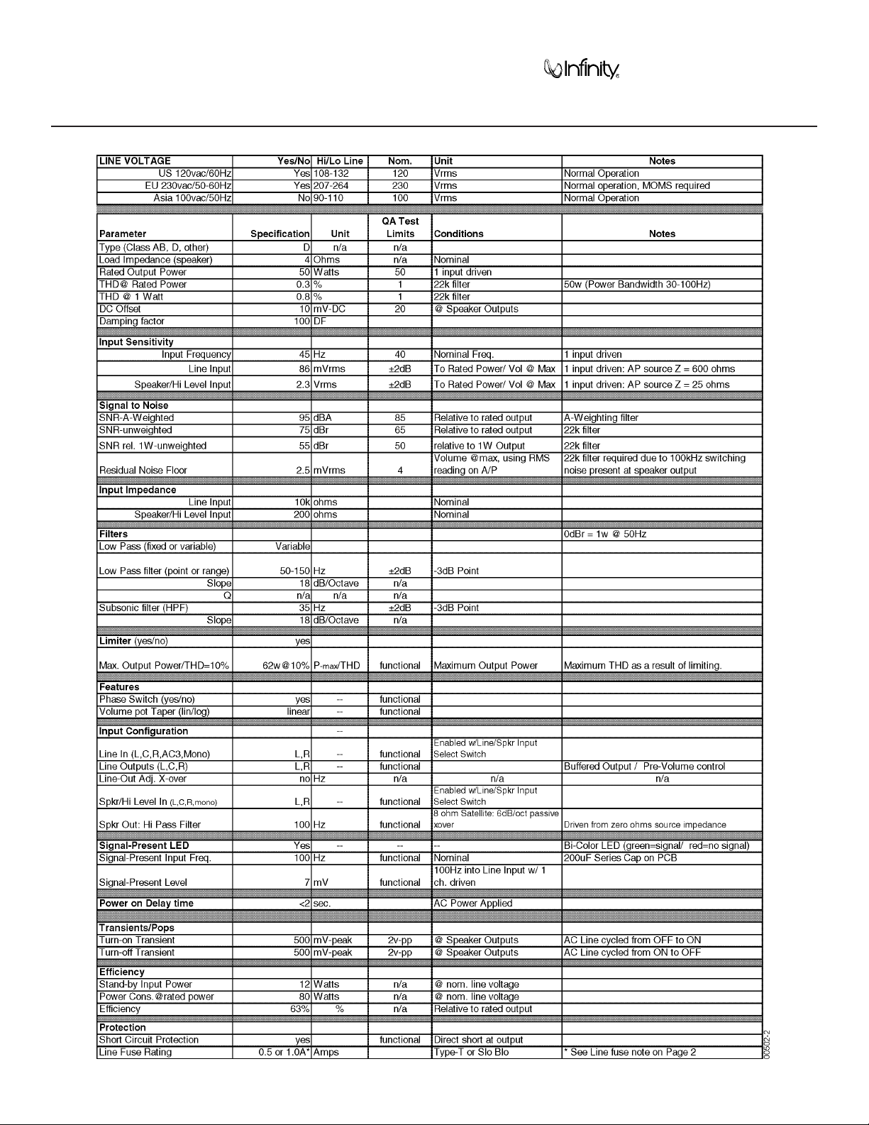
DETAILED SPECIFICATIONS
Amplifier/Subwoofer
BU-80/BU80E/HTS-10
4
Page 5
Amplifier/Subwoofer
BU-80/BU80E/HTS-10
5
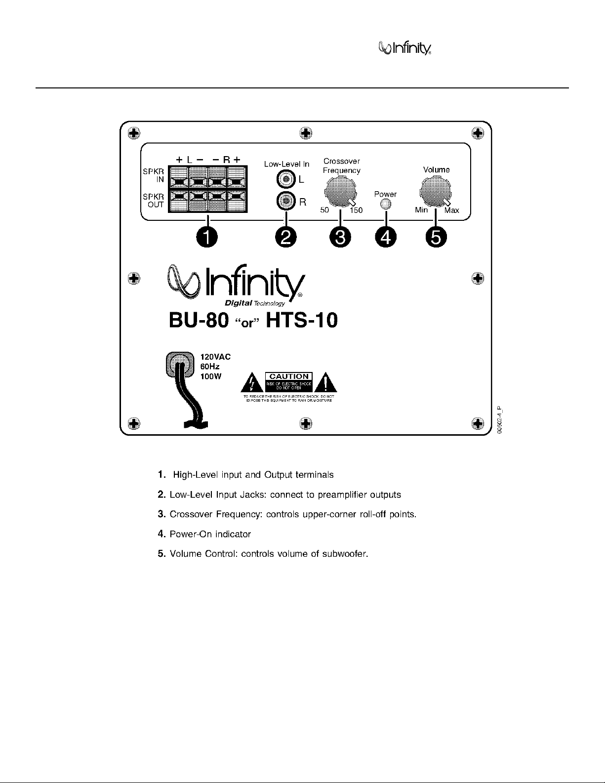
CONTROLS AND THEIR FUNCTION
Page 6
Amplifier/Subwoofer BU-80/BU80E/HTS-10
6
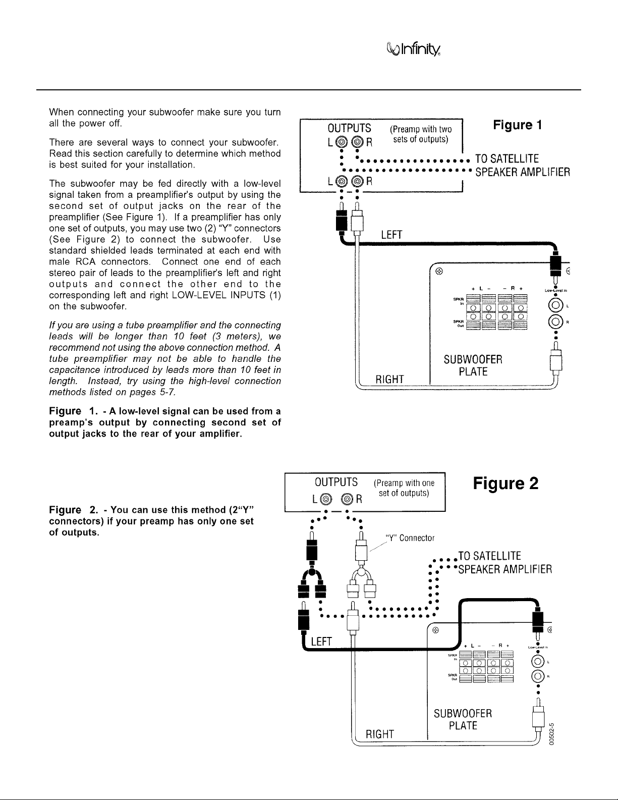
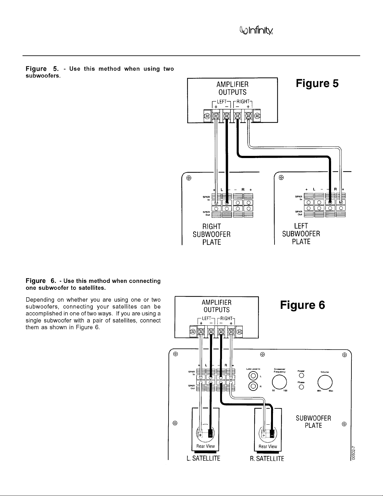
BU-80/BU80E/HTS-10 CONNECTIONS
Page 7
Amplifier/Subwoofer BU-80/BU80E/HTS-10
7
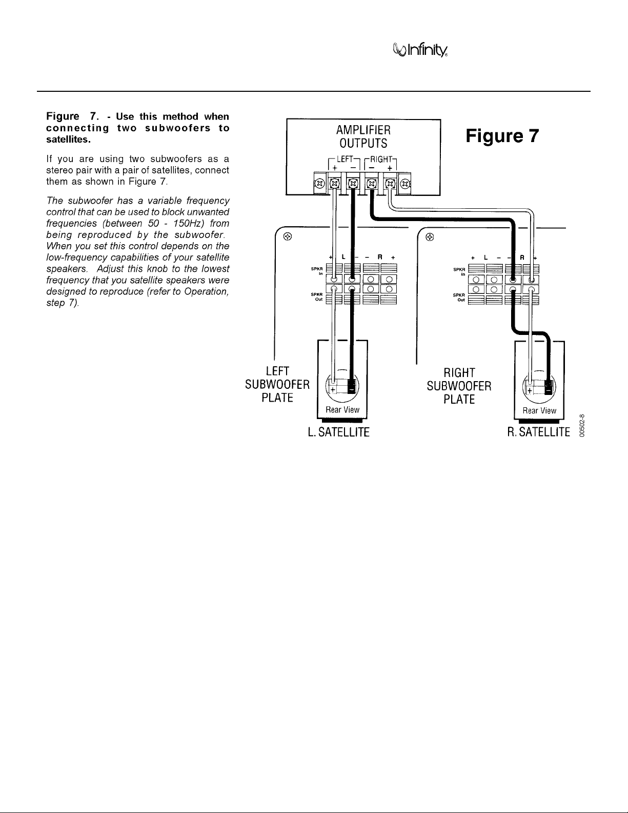
BU-80/BU80E/HTS-10 CONNECTIONS (Cont.)
Page 8
Amplifier/Subwoofer BU-80/BU80E/HTS-10
8
BU-80/BU80E/HTS-10 CONNECTIONS (Cont.)
Page 9
Amplifier/Subwoofer BU-80/BU80E/HTS-10
9
BU-80/BU80E/HTS-10 CONNECTIONS (Cont.)
Page 10
Amplifier/Subwoofer BU-80/BU80E/HTS-10
10
OPERATION
Page 11
Amplifier/Subwoofer BU-80/BU80E/HTS-10
11
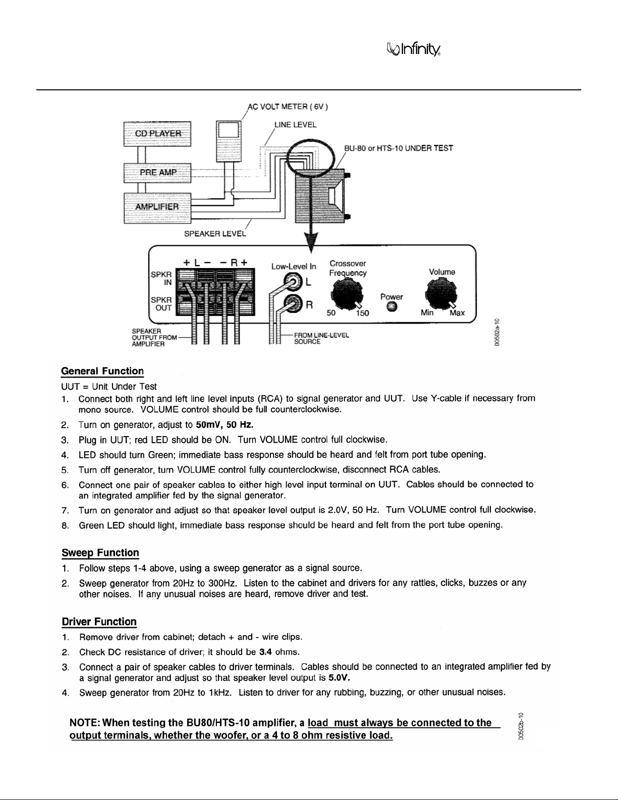
BU-80/BU80E/HTS-10 TEST SET UP AND PROCEDURE
Page 12

Amplifier/Subwoofer BU-80/HTS-10
12
BU80/HTS rev. “A, B”
Page 13

Amplifier/Subwoofer
BU-80/HTS-10
13
Power Amp Test Procedure Flow Chart BU80/HTS-10 rev. “A, B”
Page 14

Amplifier/Subwoofer
BU-80/HTS-10
14
Service Bulletin INF9902 - APRIL 1999
Page 15

Amplifier/Subwoofer
BU-80/HTS-10
15
Page 16

Amplifier/Subwoofer
BU-80/HTS-10
16
Page 17

Amplifier/Subwoofer
BU-80/HTS-10
17
TECH TIPS
Page 18

Amplifier/Subwoofer BU-80/BU80E/HTS-10
18
BU-80/BU80E/HTS-10 AMPLIFIER ASSEMBLY EXPLODED VIEW
BU80/BU80E/HTS-10
Page 19

Amplifier/Subwoofer BU-80/BU80E/HTS-10
19
BU-80/BU80E/HTS-10 AMPLIFIER ASSEMBLY EXPLODED VIEW (Cont.)
Page 20

Amplifier/Subwoofer
BU-80/BU-80EHTS-10
20
BU-80/BU-80E/HTS-10 PACKING & CABINET PARTS
FEET (SET OF 4)
BU-80/HTS-10
(rev. "A,B") 200210
BU-80E/HTS-10 (rev. "C")
061-403005-000
SCREWS (4)
8" WOOFER
BU-80/HTS-10
(rev. "A,B") 200200
BU-80E/HTS-10 (rev. "C")
090-308000-000
CABINET
NOT FOR
SALE
BU-80/BU-80E/HTS-10
CABINET ASSEMBLY
SCREWS (4)
AMPLIFIER
ASSEMBL
Y
SCREWS (8)
FEET PAD (4)
STICKERS
#200252
WARRANTY
CARD
#333715-001
OWNER'S
MANUAL
BU-80
“or”
HTS-10
OWNER'S
MANUAL
BU-80 - #200230
HTS-10 - #HTS10GUIDE
BU-80E - #008-042228-020
BU-80/BU-80E/HTS-10 PACKING
CARTON
BU-80 - #200220
HTS-10 - #HTS10CTN
BU-80E- #005-003838-000
BOTTOM STYROFOAM
RAILPADS
(2 per carton)
#200260
BU-80 "or"
HTS-10
SUBWOOFER
PLASTIC BAG
TOP
STYROFOAM
PADS
(4 per carton)
#200270
00502-19
NOTE:
The HTS-10
speakers;
subwoofer
the master carton
is part of the HTS-10
is not shown.
system
and packaged
with 5 satellite
Page 21

Amplifier/Subwoofer BU-80/HTS-10
21
BU-80/HTS-10 (rev. A, B) PCB
Page 22

Amplifier/Subwoofer
BU-80/HTS-10
22
BU-80/HTS-10 (rev. A, B) PCB
Page 23

Amplifier/Subwoofer
BU-80/HTS-10
23
BU-80/HTS-10 (rev. A, B) ELECTRICAL PARTS LIST
Page 24

Amplifier/Subwoofer
BU-80/BU-80EHTS-10
24
BU-80/HTS-10 INTEGRATED CIRCUIT/TRANSISTORS DIAGRAM
S53AM/S64AMI - Power Amp module SAFETY PART
BU-80 and HTS-10 rev “A, B” ONLY
+6V 15
16
V+
17
18
O/P
19
20
V- V-
21
22
1+6V
2
3
V+
4
O/P
5
6
7
8
+15V 23 9 +15V
SD 24
10 SD
FR 25 11 FR
I/P 26 12 I/P
GND 27 13 GND
-15V 28 14 -15V
NOTE: THE FOLLOWING PROCEDURES MUST BE FOLLOWED WHEN
INSTALLING NEW AMP MODULES:
FAILURE TO FOLLOW ONE OR MORE OF THESE STEPS MAY
RESULT IN THE INSTANT DESTRUCTION OF THE MODULE WHEN
POWERED UP.
1) Align white indent marker on Amp Module with indent marker on main
PCB; alternately position of label on the top of the module; incorrectly
0
replacing the Module 180
in the PCB slot will result in its destruction.
2) All AC powered test instruments (meters, oscilloscopes, etc.) must
have a floating ground, i.e. be connected to an isolation transformer.
3) Align and position the Amp Module before soldering.
4) Attach the amp Module with the mounting screws before soldering
powering up.
5) Use only rosin-core or non-acid core solder; thoroughly de-flux the
surfaces after soldering.
If the new Amp Module has larger mounting hole(s) in the case, and
the stock screws no longer will fit, and screws of the proper type cannot be obtained locally order:
00228
(2) part# 60301S (screws)
or
QUAD OP AMP,
LM324, TL074
U1, IC101
MOSFET TRANS
IRF530
Q2, 3
1. DRAIN
2. GATE
3. SOURCE
TRANS, PNP, 2SA1015
Q101, 104, 105
TRANS, PNP, 2N3906
MPS A56
Q2, 4, 5
(2) part# 60301N (nuts)
146V13
15
LIM
IT
V
+
TRANS, NPN, KSP113
2SC1815
Q102, 103
TRANS, NPN, 2N5551
2N3904
Q1, 3
BU-80E & HTS-10 rev “C” ONLY
12
V
+
O
V
+
/
P
V
V
-
-
+15V
V
-
5
6
7
8
9
10
11
PWR MODULE
CN101
IC 74HC14N HEX SCHMITT
TRIGGER INVERTER
U2, 3
V
A6
CC
14
13
A5
Y6
12
3
21
S/D
11
4
4IN3
Y6
10
5
2
G
-15V
N
D
A4
Y4
98
6
GNDA3Y2A2 Y3Y1A1
TRANS, NPN
MPS A13 (Darl)
1
FB
7
Q1
2
BASE
00370
JFET DUAL OPAMP
LF353N U1
1
OUT1
IN1 (–)
2
IN1 (+)
3
V
4
EE
3 COLLECTOR
1 EMITTE R
8
7
6
5
V
CC
OUT2
IN2 (–)
IN2 (+)
12
3
Page 25

Amplifier/Subwoofer
BU-80/HTS-10
25
BU-80/HTS-10 (rev. A, B) SCHEMATIC 1 OF 2
Page 26

Amplifier/Subwoofer
BU-80/HTS-10
26
BU-80/HTS (rev. A, B) SCHEMATIC 2 OF 2
Page 27

Amplifier/Subwoofer infinity BU-80/BU80E/HTS-10
27
HTS-10 ELECTRICAL PARTS LIST (Rev C version)
Part Number Description Ref. Designator Qty
MAIN PCB
Semiconductors
050-002400-100 ZENER DIODE 24V D103 1
050-003000-100 ZENER DIODE 30V D104 1
050-006200-100 ZENER DIODE 6.2V D002 1
050-414802-100 1N4148 DIODE D101,102,105,106 4
050-524500-200 ZENER DIODE 15V/1W D003,004 2
051-001300-100 TRANSISTOR KSP113 Q102 1
051-101501-000 TRANSISTOR 2SA1015 Q101,104,105 3
051-181501-100 TRANSISTOR 2SC1815 Q103 1
052-401001-000 KBU4A/100V Bridge Regulator D001 1
053-007400-000 IC TL074 Dual Op-Amp IC101 1
Resistors
020-100497-120 Carbon resistor 1K 1/4W J R132,139,140 3
020-100597-120 Carbon resistor 10K 1/4W J R107,108,R131,133,136 5
020-100697-120 Carbon resistor 100K 1/4W J R105,106,114,122,124,134,137 7
020-100797-120 Carbon resistor 1M 1/4W J R128 1
020-220797-120 Carbon resistor 2M2 1/4W J R138 1
020-330397-120 Carbon resistor 330R 1/4W J R118,119 2
020-330497-120 Carbon resistor 3K3 1/4W J R130 1
020-330597-120 Carbon resistor 33K 1/4W J R135 1
020-430497-121 Carbon resistor 4K3 1/4W J R125 1
020-470197-121 Carbon resistor 4R7 1/4W J R002 1
020-470497-120 Carbon resistor 4K7 1/4W J R117 1
020-470597-120 Carbon resistor 47K 1/4W J R123 1
020-470697-120 Carbon resistor 470K 1/4W J R129 1
020-680597-120 Carbon resistor 68K 1/4W J R109,143 2
021-100096-120 MOF RESISTOR 0R1 1/2W R141,142 2
021-100301-120 MOF RESISTOR 100R/1W R101-104 4
021-220401-021 MOF RESISTOR 2K2 1W R120,121 2
021-220402-020 MOF RESISTOR 2K2 2W R001 1
021-221597-100 MF RESISTOR 221K 1/4W F R112 1
021--249597-100 MF RESISTOR 24K9 1/4W F R115 1
021-270697-100 MF RESISTOR 270K 1/4W F R127 1
021-274697-100 MF RESISTOR 274K 1/4W F R116 1
021-280597-100 MF RESISTOR 28K 1/4W F R110 1
021-470497-100 MF RESISTOR 4K7 1/4W F R126 1
021-499597-100 MF RESISTOR 49K9 1/4W F R113 1
021-820302-020 MO 820OHM/2W R003,004 2
021-820497-100 MO 8K2 OHM/1W R111 1
026-100695-251 VR 100KB Crossover Frquency Pot VR102 1
026-500495-252 VR 5K ohm Volume Pot VR101 1
Capacitors
030-100247-300 Ceramic capacitor 0u1/50V Z P:5 C114,115,006,009,010 5
032-100163-300 mylar capacitor 0u001/100V J P:5 C103 1
032-100263-301 mylar capacitor 0u01/100V J P:5 C110 1
032-100364-300 mylar capacitor 0u1/100V K R C001,002,003,007,008, 11
104105106107108, 118
032-180364-300 mylar capacitor 0u18/100V J P:5 C116 1
032-220163-300 mylar capacitor 0u0022/100V J P:5 C109,111 2
033-220543-200 elec capacitor 22uF/50V J6R 1020 C117 1
033-220644-281 NPE capacitor 220uF/50V K10R1326 VIE C101,102 2
Page 28

Amplifier/Subwoofer infinity BU-80/BU80E/HTS-10
28
Part Number Description Ref. Designator Qty
034-100635-300 elec capacitor 100uF/35V MR 0811 P5 C113 1
034-330745-310 elec capacitor 3300uF/50V MR 1840 P7.5 C004,005 2
034-470425-300 elec capacitor 4u7/25V MR 0511 P5 C112 1
POWER AMP MODULE 1
050-414802-100 1N4148 DIODE D1-D9 9
051-530000-100 MOSFET N-CHANNEL IRF530 Q2,3 2
051-555100-000 TRANSISTOR 2N5551 Q1 1
053-035301-000 IC LF353N Dual Op-Amp U1 1
053-741400-000 IC 74HC14N Hex Schmitt Trigger Inverter U2,3 2
020-100297-120 Carbon resistor 10R 1/4W J R11,12 2
020-100397-120 Carbon resistor 100R 1/4W J R7 1
020-100497-120 Carbon resistor 1K 1/4W J R3,4,5,9 4
020-100697-120 Carbon resistor 100K 1/4W J R2 1
020-100797-120 Carbon resistor 1M 1/4W J R10 1
020-220397-121 Carbon resistor 220R 1/4W J R6 1
020-330497-120 Carbon resistor 3K3 1/4W J R8 1
020-680497-120 Carbon resistor 6K8 1/4W J R1 1
032-100394-302 MND mylar capacitor 0u1/100V K P:7.5 C9 1
034-100525-303 elec capacitor 10uF/25V M SM 4*7 C7 1
039-100343-100 mylar capacitor(axial) 100pF/50V J NPO C1,2,3,5 4
039-100345-100 mylar capacitor(axial) 0u1/50V M Z5U C4 1
039-100464-100 mylar capacitor(axial) 0u001/50V K X7R C8 1
039-330344-101 mylar capacitor(axial) 330pF/50V K X7R C6 1
072-040170-000 CONNECTOR 15PIN 1
073-014023-900 SHIELD 103.9*14*0.3t 1
073-032050-000 HEAT SINK 102.3*58mm 1
061-700012-000 Silicon Sleeves for Q2, Q3 2
FUSE PCB ASS’y
011-080203-000 FUSE PCB BOARD SWD80 82*21*1.6m/m
072-040039-000 Terminal (PCB TYPE) PC205 (t=0.8mm) J3,4,5,6 4
091-000097-000 FUSE T1A/250V 5*20mm 1
091-000130-000 FUSE HOLDER CQ-203SP(C) (0)
Miscellaneous
042-017607-004 Transformer YT-9161-2 75W-120Vac 1
073-014026-000 Metal Shield Plate
061-020000-000 knob 20x15mm ul94V-0 1
061-314002-000 cord bushing P/N SB4F-2 1
062-160400-001 Rear cover 168.6x36.8x19.9mm 1
062-211800-000 Front cover 213x178x31.5mm 1
083-041802-017 power cord spt-2 blk #18 1
043-240130-010 CHOKE COIL 2.4mH YT-8719 L001 1
043-260330-001 CHOKE COIL 0.11mH YT-8713-1 L104 1
050-505200-001 LED LT-2402-25 LED101 1
008-061007-200 GASKET MODULE BLK CR C4305 1x7x80mm 1
008-061610-201 GASKET PCB PU FOAM SM-55 3x6x200mm 1
062-050800-000 PUSH TERMINAL 8P JK101 1
070-560891-108 SCREW BTS-3 2.6x8m/m
072-010058-000 RCA JACK 2P P/N:052000W1G (Red,Wht) JK102 1
072-040032-000 Terminal P:3.96 3P CN001 1
072-040039-000 Terminal PCB TYPE PC205 (t=0.8mm) J101,102 2
091-000143-000 EMI BEAD 2
1
Page 29

Amplifier/Subwoofer BU80E/HTS-10
29
BU80E/HTS-10 REV C POWER AMP MODULE PCB
Page 30

Amplifier/Subwoofer
BU-80E/HTS-10
30
BU80E/HTS-10 REV C CIRCUIT BOARD (Cont.)
Page 31

Amplifier/Subwoofer BU80E/HTS-10
31
BU80E/HTS-10 REV C CIRCUIT BOARD (Cont.)
Page 32

Amplifier/Subwoofer
BU-80E/HTS-10
32
BU80E/HTS-10 REV C SCHEMATIC
Page 33

Amplifier/Subwoofer
BU-80E/HTS-10
33
BU80E/HTS-10 rev C POWER AMP MODULE SCHEMATIC
(IRF640)
(IRF640)
E
D
F
321
C
B
A
4321
A
B
C
8765
D
E
F
876
00503
Page 34

 Loading...