

Page 1
TECHNICAL HANDBOOK
kina26e1-p (1209)
Catalog No.
520-001
520-002
520-003
520-004
520-103
520-104
520-105
520-106
from software version V 2.9
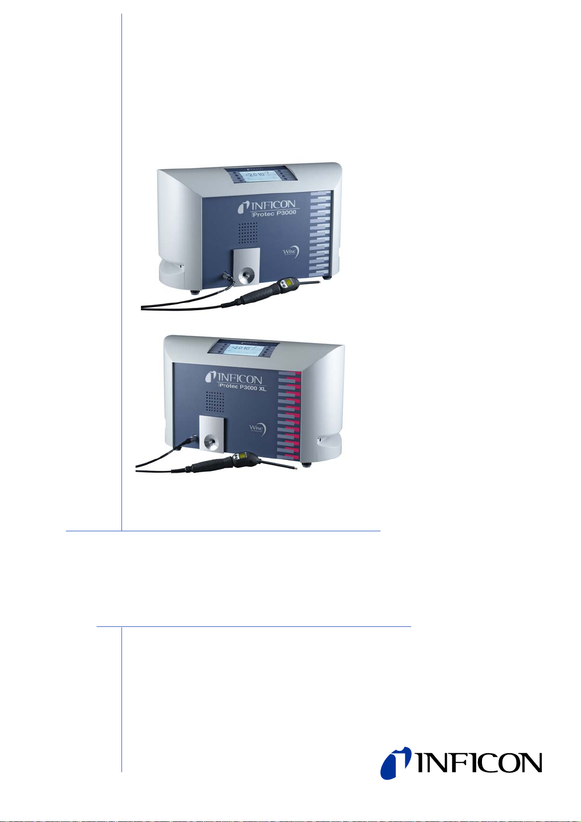
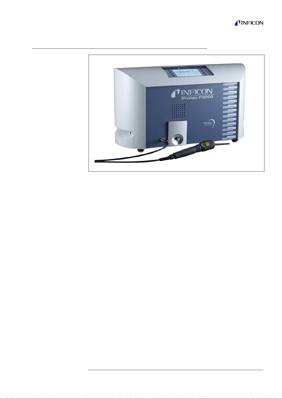
Protec P3000(XL)
Helium Sniffer Leak Detector
Page 2

0-2
kina26eIVZ.fm Technical Handbook(1209)
Page 3

Content
Content 0-3
General Safety Precautions 0-6
1 General Information 1-1
1.1 Introduction 1-1
1.1.1 Intended Use 1-1
1.1.2 Available Configurations 1-2
1.1.3 Technical Data 1-2
1.2 Support by INFICON 1-3
1.2.1 Service Centers 1-5
1.3 Unpacking 1-7
1.3.1 Supplied Equipment 1-7
1.3.2 Accessories 1-8
1.4 Notes on How to Use This Handbook 1-9
1.4.1 Symbols of Vacuum Technology 1-9
1.4.2 Definition of Terms 1-10
1.5 Instrument Views of the Protec P3000 1-11
1.6 Installation 1-12
1.6.1 Set up 1-12
1.6.2 Mechanical Connections 1-13
1.6.3 Electrical Connections 1-16
1.6.4 RS232 Interface 1-17
1.6.5 I/O Port 1-17
2 How the Protec P3000 Works 2-1
2.1 Description of the Functions 2-1
2.2 Description of the Subassemblies 2-1
2.2.1 Backing Pump 2-1
2.2.2 Wise TechnologyTM Sensor 2-1
2.2.3 Valve Holder 2-2
2.2.4 Control Assembly 2-2
2.3 Description of the Displays and User Interfaces 2-2
2.3.1 Main unit display 2-2
2.3.2 SL3000(XL) Sniffer line with probe display 2-4
2.3.3 Built-in PRO-Check reference leak 2-5
3 Operation of the Protec P3000 3-1
3.1 Start-Up 3-1
3.2 Controls on the main display unit 3-2
3.3 Controls on the probe display unit 3-5
3.4 Performing measurements 3-5
3.4.1 Standard Operation Mode 3-6
3.4.2 I•Guide Operating Mode 3-9
3.4.2.1 Starting the I•Guide Mode 3-9
3.4.2.2 Selecting an I•Guide Program 3-10
kina26eIVZ.fm Technical Handbook(1209)
3.4.2.3 Using an I•Guide Program 3-10
3.4.3 The Info Page 3-13
Content 0-3
Page 4

3.5 Calibration and Self-Test 3-15
3.5.1 Verifying a calibration (proof function) 3-15
3.5.2 Internal cali bration 3-17
3.5.3 External calibration 3-17
3.6 Standby 3-20
3.7 Shutdown 3-20
3.8 Storage for fast availability as back-up unit 3-20
4 Equipment Settings 4-1
4.1 Menu Structure 4-1
4.2 The Service Menu 4-3
4.3 Selecting gas equivalents and setting trigger values 4-3
4.3.1 Setting gas parameters 4-3
4.3.2 Selecting a set of gas parameters 4-7
4.4 Settings Sub-menu 4-8
4.4.1 Vacuum & Access 4-8
4.4.2 Audio Functions 4-15
4.4.3 Display Settings 4-17
4.4.4 Setting-up / editing an I•Guide Program 4-19
4.4.5 Miscellaneous Settings 4-21
4.5 Interfaces 4-23
4.5.1 Control location 4-23
4.5.2 Recorder outputs 4-23
4.5.3 RS232 Protocol 4-25
4.5.4 Select PLC inputs 4-27
4.5.5 Baud rate & end sign 4-27
4.5.6 PRO-Check (only available in advanced mode) 4-27
4.6 The Info Menu 4-28
4.7 History & Maintenance 4-32
5 Protec P3000 Messages 5-1
5.1 Error Messages and Warnings 5-1
6 Equipment Connections 6-1
6.1 I/O Port (Control Inputs and Outputs) 6-1
6.1.1 Ground connectors 6-2
6.1.2 24V Output 6-2
6.1.3 PLC Inputs 6-2
6.1.4 PLC Outputs 6-3
6.1.4.1 Relay outputs 6-5
6.1.4.2 Recorder Outputs 6-5
6.1.5 How to perform a calibration? 6-6
6.2 RS232 interface 6-7
7 Maintenance 7-1
7.1 Maintenance schedule 7-1
7.2 Exchanging the air filter 7-2
7.3 Exchanging the external fuses 7-4
kina26eIVZ.fm Technical Handbook(1209)
0-4 Content
Page 5

7.4 Replacing filters in the sniffer line 7-4
7.4.1 Replacing the felt discs of the capillary filter
(for SL3000 only) 7-5
7.4.2 Replacing the felt discs when using the water
protection tip (for SL3000 only) 7-7
7.4.3 Checking / replacing the sinter filter
(for SL3000 only) 7-7
7.5 Replacing the filter pad of the sniffer tip
(for SL3000XL only) 7-9
7.6 Switching the capillary filter
(for SL3000 sniffer line only) 7-11
7.6.1 Switching from metal to plastic capillary filter 7-11
7.6.2 Switching from plastic to metal capillary filter 7-12
7.7 Replacing the gas reservoir of the
PRO-Check 7-13
8 The gas library 8-1
kina26eIVZ.fm Technical Handbook(1209)
Content 0-5
Page 6
General Safety Precautions
Warning
Caution
Warning
Warning
Indicates procedures that must be strictly observed to prevent haza rd s to per sons.
Indicates procedures that must strictly be observed to prevent damage to or
destruction of the Protec P3000 leak detector.
Notice Indicates special requirements the user must comply with.
The INFICON Protec P3000 leak detector has been designed for safe and efficient
operation when used properly and in accordance with this Technica l Handb ook. It is
the responsibility of the user to carefully read and strictly observe all safety
precautions described in this chapter and throughout this Technical Handbook. The
Protec P3000 must only be operated in the proper condition and under th e conditions
described in this Technical Handbook. It must be operated and maintained by train ed
personal only. Consult local, state, and national agencies regarding specific
requirements and regulations. Adress any further safety, operation and / or
maintenance questions to our nearest office.
Failure to observe the following precautions could result in serious personal
injury:
Danger of explosion!
To use the Protec P3000 in explosion hazard areas could cause ignition of
flammable mixtures.
The Protec P3000 must only be operated outside of explosion hazard areas.
Only 3-core mains cables having a protective ground conductor must be used.
Operation of the Protec P3000 with the ground conductor unconnected is not
permissible.
kina26eIVZ.fm Technical Handbook(1209)
0-6 General Safety Precautions
Page 7
Warning
Do not stare into the LEDs of the sniffer line intentionally for extended times or at a
Warning
Warning
Warning
Warning
Warning
close distance as this may cause permanent damage to the eye.
Danger of electric shock.
Don’t touch voltaged parts with the sniffer tip. Test samples need to be
disconnected from electricity before leak testing.
For all contacts of the I/O Port a maximum voltage of 60 V DC or 25 V AC must not
be exeeded or reached to ground or ground equipment conductors.
According to the type of in- or outputs lower voltages had to be accepted. For this,
please refer to the information given in the responding chapters.
For all maintenance on the Protec P3000, the Protec P3000 must be disconnected
from power.
Before exchanging the air filter the Protec P3000 must be disconnected from
power.
Before exchanging the fuses the Protec P3000 must be disconnected from power.
kina26eIVZ.fm Technical Handbook(1209)
General Safety Precautions 0-7
Page 8
Failure to observe the following precautions could result in damage to the
Caution
Caution
Caution
Caution
Caution
Caution
Caution
equipment:
The Protec P3000 must not be operated while standing in water or when exposed
to drip water. The same applies to all other kinds of liquids.
This Protec P3000 should only be used in rooms.
Avoid contact of the Protec P3000 with bases, acids and solvents as well as
exposure to extreme climatic conditions.
Ensure sufficient air cooling (see also Section 1.1.2)
Before installation remove the transportation lock.
In order to ensure adequate ventilation of the Protec P3000, a space of at least
20 cm 8) (8 in.) must be kept unobstructed to the sides. The clearance at the rear
must be no less than 10 cm (4 in.). Moreover, the Protec P3000 handles for carrying
the leak detector at the sides of the main unit must not be covered at any time as
these acts as air inlet and outlet. Avoid the presence of heat sources in the vicinity
of the Protec P3000.
Before connecting the Protec P3000 to the mains you must make sure that the
mains voltage rating of the Protec P3000 coincides with the locally available mains
voltage.
Do not suck in any liquids.
0-8 General Safety Precautions
kina26eIVZ.fm Technical Handbook(1209)
Page 9
Caution
Permissible maximum input voltage PLC 28 V.
Caution
Caution
Caution
Permissible max. voltage and current for open collector outputs are: 28 V; 50 mA.
Maximum load rating relay outputs is 60 V DC / 25 V AC and 1 A per relay.
The air filter should be checked for contamination at least every 6 months and
should be definitely exchanged after 2 years.
kina26eIVZ.fm Technical Handbook(1209)
General Safety Precautions 0-9
Page 10

0-10 General Safety Precautions
kina26eIVZ.fm Technical Handbook(1209)
Page 11
1 General Information
Caution
Caution
Caution
The Protec P3000 helium leak detector is supplied ready for operation. However, we
recommend that you carefully read the Technical Handbook to ensure optimum
operating conditions right from the start. This handbook contains important
information on functions, installation, start-up and operation of the Protec P3000.
If not stated otherwise this technical handbook applies to all three configurations of
the Protec P3000 (see Section 1.1.2). Sections specific to one configuration are
marked as "for … only". Sections marked as "for Protec P300 0XL only" always apply
to the Protec P3000XL with the SL3000XL sniffer line (capable of
1.1 Introduction
1.1.1 Intended Use
The Protec P3000 is a helium leak detector for sniffer applications. It may be used to
localise and quantify leaks in test samples if there is helium under an overpressure
within the test sample and when searching the test sample with a sniffer probe from
the outside (sniffer method). The use of this sniffer probe is mandatory for proper
operation and it is available as an accessory (Cat. No. 525-001 to 525-004).
HIGH FLOW mode).
The Protec P3000 must not be operated while standing in water or when exp osed
to drip water. The same applies to all other kinds of liquids.
This Protec P3000 should only be used in rooms.
Avoid contact of the Protec P3000 with bases, acids and solvents as well as
exposure to extreme climatic conditions.
Ensure sufficient air cooling (see also Section 1.1.2)
kina26e Chapter 1.fm Technical Handboook(1209)
General Information 1-1
Page 12

1.1.2 Available Configurations
The Protec P3000 leak detector is available in four different configurations:
The Standard Pr otec
P3000
The standard Protec P3000 should be used for high sensitivity applications. It
requires the SL3000 sniffer line.
The Protec P3000,
RC version
The Protec P3000, RC version is the standard Protec P3000 but with an external
display unit. It requires the SL3000 sniffer line.
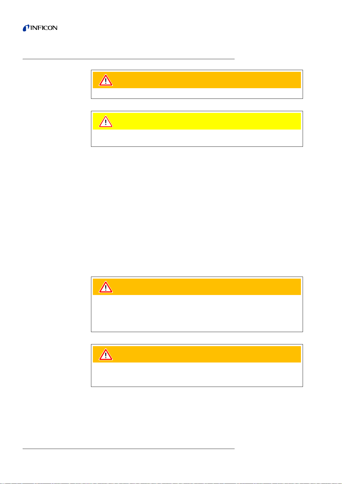
The Protec P3000XL
The Protec P3000XL is the
leaks at a much higher distance from the potential leak at reduced sensitivity but can
be switched back to normal flow at inc reased sensitivity. In order to use both flow
modes (high and low) it requires the use of the SL 3000XL sniffer line. It may also be
operated with the normal SL3000 sniffer line, in this case the high flow mode is
disabled, however.
The Protec P3000XL,
RC version
The Protec P3000XL, RC version is identical to the Protec P3000XL, but with an
external display unit. It requires the SL3000XL sniffer line.
1.1.3 Technical Data
Physical Data
Lowest detectable leak rate
Measurement range
Helium sensor Wise Technology
Sensor response time 450 ms
HIGH FLOW version of the Protec P3000. It is able to detect
For Protec P3000 1 x 10
For Protec P3000XL in
For Protec P3000XL in
LOW FLOW mode 1 x 10
HIGH FLOW mode 1 x 10
-7
mbar l/s
-7
mbar l/s
-6
mbar l/s
For Protec P3000 5 decades
For Protec P3000XL in
HIGH FLOW mode 4 decades
TM
Sensor
1-2 General Information
kina26e Chapter 1.fm Technical Handboook(1209)
Page 13

Electrical Data
Other data
Gas flow through the capillary
For Protec P3000 260 - 360 sccm*
For Protec P3000XL in
HIGH FLOW mode 2660 - 3500 sccm*
Time until ready for operation approx. 3 min
* Measured at 1 atm (1013 mbar) at sea altitude. Actual flow may vary with increased
altitude and low atmospheric pressure.
Mains voltages and mains frequencies 90 - 127 V, 50 / 60 Hz
(fixed) 115 - 140 V, 60 Hz
187 - 265 V, 50 / 60 Hz
Power consumption 200 VA
Type of protection IP 20
Overvoltage category II
Mains cord 2.5 m
Noise level < 54 dBA
Dimensions (w x h x d) in mm 610 x 370 x 265
Weight 27 kg
Permissible ambient temperature
10 °C to 45 °C
(during operation)
Permissible storage temperature -40 °C to 60 °C
Relative humidity max. 80% for temperature up to +31°C,
decreasing linearly to 50% at +40°C
Contamination level II
(according to IEC 61010 / Part 1:
“normally only non-conductive pollution
may occur. Occasionally, however, a
temporary conductivity caused by
condensation can be tolerated.”)
Max. altitude above sea level 2000m
1.2 Support by INFICON
INFICON Service
If equipment is returned to INFICON or an authorised INFICON representative
indicate whether the equipment is free of substances damaging to health o r whether
it is contaminated. If it is contaminated also indicate the nature of the hazard.
INFICON must return any equipment without a Declaration of Contamination to the
sender’s address. You will find an appropriate form below.
kina26e Chapter 1.fm Technical Handboook(1209)
General Information 1-3
Page 14
General
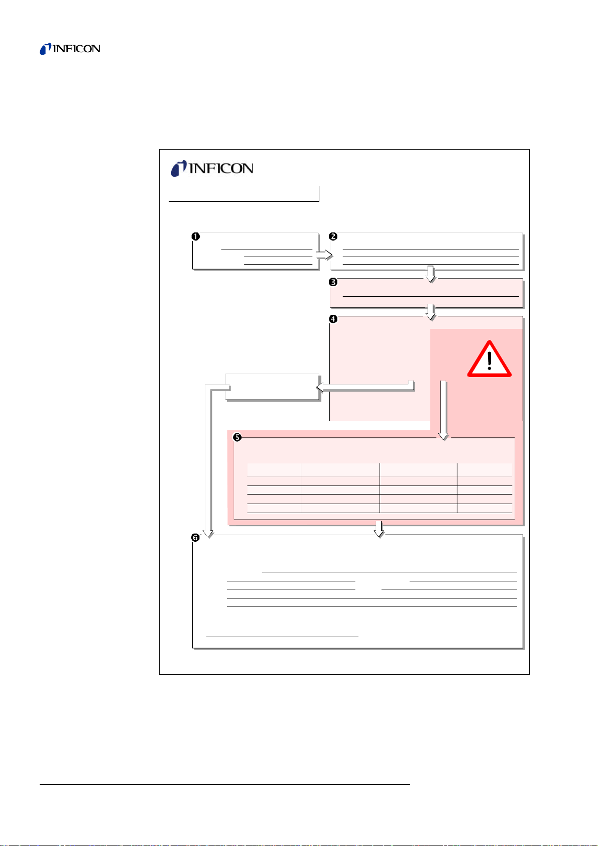
Declaration of Contamination
Legally binding declaration:
I/we hereby declare that the information on this form is complete and accurate and that I/we will assume any further costs that may
arise. The contaminated product will be dispatched in accordance with the applicable regulations.
Organization/company
Address Post code, place
Phone Fax
Email
Name
Date and legally binding signature Company stamp
1) or not containing any amount
of hazardous residues that
exceed the permissible ex posure limits
Process related contamination of product:
toxic no 1) yes
caustic no 1) yes
biological hazard no
yes 2)
explosive no
yes 2)
radioactive no
yes 2)
other harmful substances n o1) yes
The service, repair, and/or disposal of vacuum equipment and components will only be carried out if a correctly completed declaration has
been submitted. Non-completion will result in delay.
This declaration may only be completed (in block letters) and signed by authorized and qualified staff.
Copies:
Original for addressee - 1 copy for accompanying documents - 1 copy for file of sender
Harmful substances, gases and/or by-products
Please list all substances, gases, and by-products which the product may have come into contact with:
Trade/product name
Chemical name
(or symbol)
Precautions associated
with substance
Action if human contact
Description of product
Type
Article Number
Serial Number
Reason for return
Operating fluid(s) used (Must be drained before shipping.)
The product is free of any substances which are damaging to
health yes
This form can be downloaded
from our website.
2) Products thus contam i nated will not be ac cepted without written
evidence of decontam i nation!
We reserve the right to alter the design or any data given in this handbook.
The illustrations are not binding.
Fig. 1-1 Declaration of Contamination
1-4 General Information
kina26e Chapter 1.fm Technical Handboook(1209)
Page 15

1.2.1 Service Centers
Algeria jhj@agramkow.dk Finland jhj@agramkow.dk
Agramkow
Sonderborg
Belarus leakdetection.service@inficon.com France Christophe.Zaffanella@oerlikon.com
INFICON GmbH
Cologne
Belgium leakdetection.service@inficon.com Germany leakdetection.service@inficon.com
INFICON GmbH
Cologne
Brazil fernandoz@prestvacuo.com.br Hungary adam.lovics@kon-trade.hu
PV Pest Vácuo Ltda.
Santa de Parnaíba
Bulgaria leakdetection.service@inficon.com India asdash@hotmail.com
INFICON GmbH
Cologne
Canada reachus@vpcinc.ca Ireland reach.unitedkingdom@inficon.com
Vacuum Products Canada Ltd.
Ontario
Central America infoqro@meisa.com Italy davide.giovanetti@inficon.com
MEISA S.a. de C.V.
Querètaro
China reach.china@inficon.com Israel urimark@mark-tec.co.il
INFICON LTD
Hong Kong
INFICON LTD
Beijing
INFICON LTD
Guangzhou
INFICON LTD
Shanghai
Czech Republic filip.lisec@inficon.com Korea reach.korea@inficon.com
INFICON GmbH
Pilsen
Denmark jhj@agramkow.dk INFICON Ltd.
Agramkow
Sonderborg
Egypt jhj@agramkow.dk Latvia leakdetection.service@inficon.com
Agramkow
Sonderborg
Estonia leakdetection.service@inficon.com Lithuania leakdetection.service@inficon.com
INFICON GmbH
Cologne
Phone: +45 741 236 36
Fax: +45 744 336 46
Phone: +49 221 56788-112
Fax: +49 221 56788-9112
Phone: +49 221 56788-112
Fax: +49 221 56788-9112
Phone: +55 114 154 4888
Fax: +55 114 154 4888
Phone: +49 221 56788-112
Fax: +49 221 56788-9112
Phone: +905.672.7704
Fax: +905.672.2249
Phone: +52 44 22 25 42 80
Fax: +52 44 22 25 41 57
Phone: +852.2862.8863
Fax: +852.2865.6883
Phone: +86.10.6590.0164
Fax: +86.10.6590.0521
Phone: +86.20.8723.6889
Fax: +86.20.8723.6003
Phone: +86.21.6209.3094
Fax: +86.21.6295.2852
Phone +420 734 331 758
Fax: +420 604 203 037
Phone: +45 744 336 36
Fax: +45 744 336 46
Phone: +45 741 236 36
Fax: +45 744 336 46
Phone: +49 221 56788-112
Fax: +49 221 56788-9112
Agramkow
Sonderborg
OLV France
Orsay
INFICON GmbH
Cologne
Kontrade
Budaörs
Dashpute
400 064
INFICON
Blackburn
INFICON GmbH
Castelnuovo
Mark Technologies Ltd.
Kiriat Ono
Japan reach.japan@inficon.com
INFICON Co. Ltd.
Yokohama
INFICON Ltd.
Sungnam city
Suwon City
INFICON Ltd.
Cheonan City
INFICON GmbH
Cologne
INFICON GmbH
Cologne
Phone: +45 741 236 36
Fax: +45 744 336 46
Phone: +33 476 351 584
Fax: +33 476 351 584
Phone: +49 221 56788-112
Fax: +49 221 56788-9112
Phone: +36 23 50 38 80
Fax: +36 23 50 38 96
Phone: +91 22 888 0324
Fax: +91 22 888 0324
Phone: +44 1254 678 250
Fax: +44 1254 698 577
Phone: +39 045 6 40 25 56
Fax: +39 045 6 40 24 21
Phone: +972 35 34 68 22
Fax: +972 35 34 25 89
Phone: +81.45.471.3396
Fax: +81.45.471.3387
Phone: +82 312 062 890
Fax: +82 312 063 058
Phone: +82 312 062 890
Fax: +82 312 063 058
Phone: +82 312 062 890
Fax: +82 312 063 058
Phone: +49 221 56788-112
Fax: +49 221 56788-9112
Phone: +49 221 56788-112
Fax: +49 221 56788-9112
kina26e Chapter 1.fm Technical Handboook(1209)
General Information 1-5
Page 16

Mexico infoqro@meisa.com Spain richard.cunill@leyboldoptics.com
MEISA S.a. de C.V.
Querètaro
Netherlands leakdetection.service@inficon.com Sweden jhj@agramkow.dk
INFICON GmbH
Cologne
Norway jhj@agramkow.dk Syria leakdetection.service@inficon.com
Agramkow
Sonderborg
Poland kamola@vakpol.com Taiwan Susan.Chang@inficon.com
VAK-POL & GAZ Sp. zo.o
Pulawy
Portugal leakdetection.service@inficon.com Tunisia leakdetection.service@inficon.com
INFICON GmbH
Cologne
Republic of South Africa vacuquip@hotmail.com Turkey jhj@agramkow.dk
Vacuquip
Randburg
Russia leakdetection.service@inficon.com Ukraine leakdetection.service@inficon.com
INFICON GmbH
Cologne
Singapore reach.singapore@inficon.com United Kingdom reach.unitedkingdom@inficon.com
INFICON PTE LTD.
Singapur
Slovakia filip.lisec@inficon.com United Arab Emirates leakdetection.service@inficon.com
INFICON GmbH
Pilsen
Slovenia medivak@siol.net USA service.usa@inficon.com
Medivac
Ljubljani
South America except Brazil infoqro@meisa.com Inficon Inc.
MEISA S.a. de C.V.
Querètaro
Phone: +52 442 225 42 80
Fax: +52 442 225 41 57
Phone: +49 221 56788-112
Fax: +49 221 56788-9112
Phone: +45 741 236 36
Fax: +45 744 336 46
Phone: +48 60 23 15 212
Fax: +48 60 23 15 212
Phone: +49 221 56788-112
Fax: +49 221 56788-9112
Phone: +27 73 15 78 355 Agramkow
Phone: +49 221 56788-112
Fax: +49 221 56788-9112
Phone: +65.890.6250
Fax: +65.890.6266
Phone +420 734 331 758
Fax: +420 604 203 037
Phone: +386 15 63 91 50
Fax: +386 17 22 04 51
Phone: +52 44 22 12 36 15
Fax: +52 44 22 12 19 40
Leybold Optics Ibérica
Barcelona
Agramkow
Sonderborg
INFICON GmbH
Cologne
INFICON Company Limited
Chupei City, HsinChu Hsien
INFICON GmbH
Cologne
Sonderborg
INFICON GmbH
Cologne
INFICON
Blackburn
INFICON GmbH
Cologne
Inficon Inc.
East Syracuse, NY
San Jose, CA
Inficon Inc.
Austin, TX
Phone: +34 93 66 60 778
Fax: +34 93 66 64 612
Phone: +45 741 236 36
Fax: +45 744 336 46
Phone: +49 221 56788-112
Fax: +49 221 56788-9112
Phone: +886.3.5525.828
Fax: +886.3.5525.829
Phone: +49 221 56788-112
Fax: +49 221 56788-9112
Phone: +45 741 236 36
Fax: +45 744 336 46
Phone: +49 221 56788-112
Fax: +49 221 56788-9112
Phone: +44 1254 678 250
Fax: +44 1254 698 577
Phone: +49 221 56788-112
Fax: +49 221 56788-9112
Phone: +1.315.434.1167
Fax: +1.315.434.2551
Phone: +1.408.361.1200
Fax: +1.408.362.1556
Phone: +1.512.448.0488
Fax: +1.512.448.0398
1-6 General Information
kina26e Chapter 1.fm Technical Handboook(1209)
Page 17

1.3 Unpacking
Unpack the Protec P3000 leak detector immediately after it has been received even
if it is to be put into operation at some later date. Examine the shipping container for
any external damage. Completely remove all packaging materials.
Notice Retain the shipping container and the packaging materials in the event of
possible complaints concerning any damages.
Check if the Protec P3000 leak detector is complete (see Section 1.3.1) and carefully
subject it to a visual inspection. If any damage is discovered please immediately
inform the forwarding agent and the insurers. If it is required to exchange the
damaged part please contact our or ders department.
1.3.1 Supplied Equipment
The Protec P3000 leak detector is ready for operation. Before installation please
read Section 1.5. Included with the leak detector are the following items:
• Protec P3000 (main unit)
• Mains cord, 3m long
• Set of fuses (3 x 10 pcs.)
• Spare air filter
• 8 mm hexagonal wrench
• Documentation
– Operating Instructions (kima26)
– Technical Handbook Protec P3000 (kina26e1)
– Spare Parts List Protec P3000 (kiua26d2)
– Interface Description Protec P3000 (kins26e1)
Notice The SL3000 and SL3000XL sniffer lines are available in different
configurations and need to be ordered separately in the desired length. The
SL3000(XL) sniffer line is not part of the Protec P3000 shipment. (see
Section 1.3.2 Accessories)
Notice The PRO-Check reference leak is an accessory (see Section 1.3.2
Accessories) and needs to be ordered seperately
Notice For the RC versions the display unit and the co nnecting cable ar e not part
of the standard Protec P3000 shipment and need to be ordered separate ly
(see Section 1.3.2)
kina26e Chapter 1.fm Technical Handboook(1209)
General Information 1-7
Page 18

1.3.2 Accessories
For Protec P3000
SL3000 Sniffer line for Protec P3000 Cat. No. / Ref. No.
SL3000-3, 3 m length 525-001
SL3000-5, 5 m length 525-002
SL3000-10, 10 m length 525-003
SL3000-15, 15 m length 525-004
Sniffer tips for SL3000
ST 312, 120 mm, rigid 122 13
FT 312, 120 mm, flexible 122 14
FT 200, 200 mm, rigid 122 18
FT 250, 250 mm, flexible 122 66
ST 385, 385 mm, rigid 122 15
FT 385, 385 mm, flexible 122 16
FT 600, 600 mm, flexible 122 09
ST 500, 500 mm, rigid, 45° angled 122 75
Water protection tip for sniffer 122 46
For Protec P3000XL only
SL3000XL Sniffer line for Protec P3000XL
Sniffer tips for SL3000XL
For RC versions only
External display unit
Connecting cable for external display unit
Connecting cable for external display unit
SL3000XL-3, 3 m length 521-011
SL3000XL-5, 5 m length 521-012
SL3000XL-10, 10 m length 521-013
SL3000XL-15, 15 m length 521-014
ST 312XL, 120 mm, rigid 122 80
FT 312XL, 120 mm, flexible 122 81
ST 385XL, 385 mm, rigid 122 82
FT 385XL, 385 mm, flexible 122 83
FT 250XL, 250 mm, flexible 122 85
for benchtop use 551-100
for rack mounting 551-101
5m length 551-102
0.7m length 551-003
kina26e Chapter 1.fm Technical Handboook(1209)
1-8 General Information
Page 19
For all Protec P3000
Warning
Caution
configurations
Holder for SL3000(XL) 525-006
PRO-Check reference leak for helium 521-001
Calibrated sniffer leaks for helium
S-TL 4, approx.1 x 10
S-TL 5, range 10
S-TL 6, range 10
-4
mbar l/s 122 37
-5
mbar l/s 122 38
-6
mbar l/s 122 39
1.4 Notes on How to Use This Handbook
Important remarks concerning operational safety and protection are emphasised as
follows:
Notice Indicates special requirements the user must comply with.
Indicates procedures that must be strictly observed to prevent hazards to persons.
Indicates procedures that must strictly be observed to prevent damage to or
destruction of the Protec P3000 leak detector.
The references to diagrams, e.g. (2-1/6) consist of the Section No., Fig. No. and the
Item No. in that order. For example: (2-1/6) means Section 2, Fig. 1 and Item No. 6
(here: mains switch).
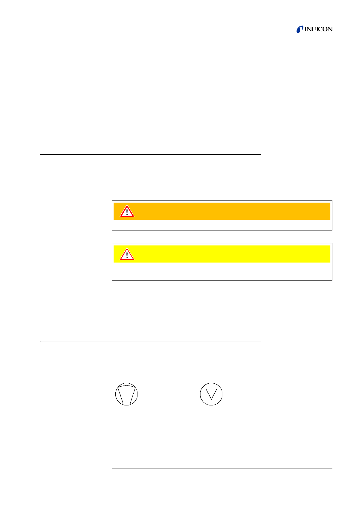
1.4.1 Symbols of Vacuum Technology
In the following some important symbols of vacuum technology as used in this
handbook are shown:
Diaphragm pump Vacuum gauge
kina26e Chapter 1.fm Technical Handboook(1209)
General Information 1-9
Page 20

1.4.2 Definition of Terms
Main menu
This menu is shown first after operating the Menu push-button.
Sub-menus
Comprise all menus which may be accessed from the main menu. Unauthorised
changes to many of these sub-menus may be prevented by a password (see also
Section 4.3.1).
Menu item
A single menu line.
Default condition
Status of the Protec P3000 when supplied from the factory.
Service menu
Comprises the menu lines in the “Service” sub-menu. The service menu is accessed
by scrolling in the basic menu using the navigation push-b uttons (see also Section
3.2).
Autozero
Determination and compensation of the helium background. With this function, the
internal ZERO level of the leak rate signal is determined in order to avoid a readout
of the internal helium background and mistaking it as a properly measured value. If
subsequently negative leak rates are obtained due to this correction , the stored offset
values are changed so that ZERO will be the lowest value which can be obtained. In
this way the values adapt automatically to a decaying background (adaptive
background correction).
Internal background
The existing partial pressure in the measurement system. The level of the internal
background is measured all the time and subtracted from the measured signal.
I•Guide Mode
In the I•Guide Mode different testing plans can be pre-programmed. During testing
the operator is then constantly prompted for the next action and thus guid ed through
the testing plan.
Unit under test
Test object that needs to be leak checked.
Display limit
Limits the measurement data displayed depending on the unit of measurement and
the operator settings.
1-10 General Information
kina26e Chapter 1.fm Technical Handboook(1209)
Page 21
1.5 Instrument Views of the Protec P3000
1
2
3
4
5
Fig. 1-2 Instrument views of Protec P3000
Pos. Description Pos. Description
1 Main display 4 Lemo Connector for SL3000 sniffer line
2 Speaker 5 Handle fore carrying the Protec P3000
3 PRO-Check reference leak
kina26e Chapter 1.fm Technical Handboook(1209)
General Information 1-11
Page 22
1.6 Installation
Caution
Caution
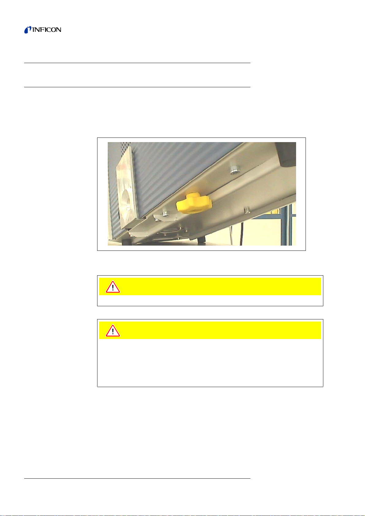
1.6.1 Set up
How to remove the transportation lock:
The transportation lock is located on the bottom side of the Protec P3000 and
consists of a yellow knurled screws. Please remove this screw before starting-up the
leak detector. The Protec P3000 is supplied ready for operation. Initial start-up is
described in Section 3.1.
Fig. 1-3 Removing the transportation lock before starting
Before installation remove the transportation lock.
In order to ensure adequate ventilation of the Protec P3000, a space of at least
20 cm 8) (8 in.) must be kept unobstructed to the sides. The clearance at the rear
must be no less than 10 cm (4 in.). Moreover, the Protec P3000 handles for carrying
the leak detector at the sides of the main unit must not be covered at any time as
these acts as air inlet and outlet. Avoid the presence of heat sources in the vicinity
of the Protec P3000.
1-12 General Information
kina26e Chapter 1.fm Technical Handboook(1209)
Page 23
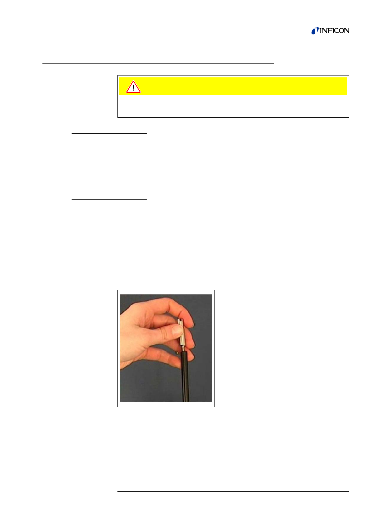
1.6.2 Mechanical Connections
Caution
Twisting the sniffer line spoils the cable.
Do not twist the sniffer line.
SL3000(XL) Sniffer line
In order to operate the Protec P3000 it is essential for the SL3000(XL) sniffer line to
be connected. The connection for the sn iffe r line is loca te d at the fro nt of the Prot ec
P3000 left of the PRO-Check reference leak. Insert th e plug into the opening with the
red dot on the plug and the slot in the front cover aligned until the connector engage s.
To disconnect the plug, retract the coupling and remove the probe’s line.
Water protection tip
(optional)
If you intend to perform leak testing on parts that are not completely dry (e.g. due to
condensation after performance testing), we strongly recommend to use a water
protection tip.
To install the water protection tip,
1 screw off the metallic capillary filter at the very end of the sniffer tip and
2 install the water protection tip instead.
Notice Please do not forget to re-install the little rubber se al when switching to the
water protection tip.
Fig. 1-4 Installing water protection tip
kina26e Chapter 1.fm Technical Handboook(1209)
General Information 1-13
Page 24
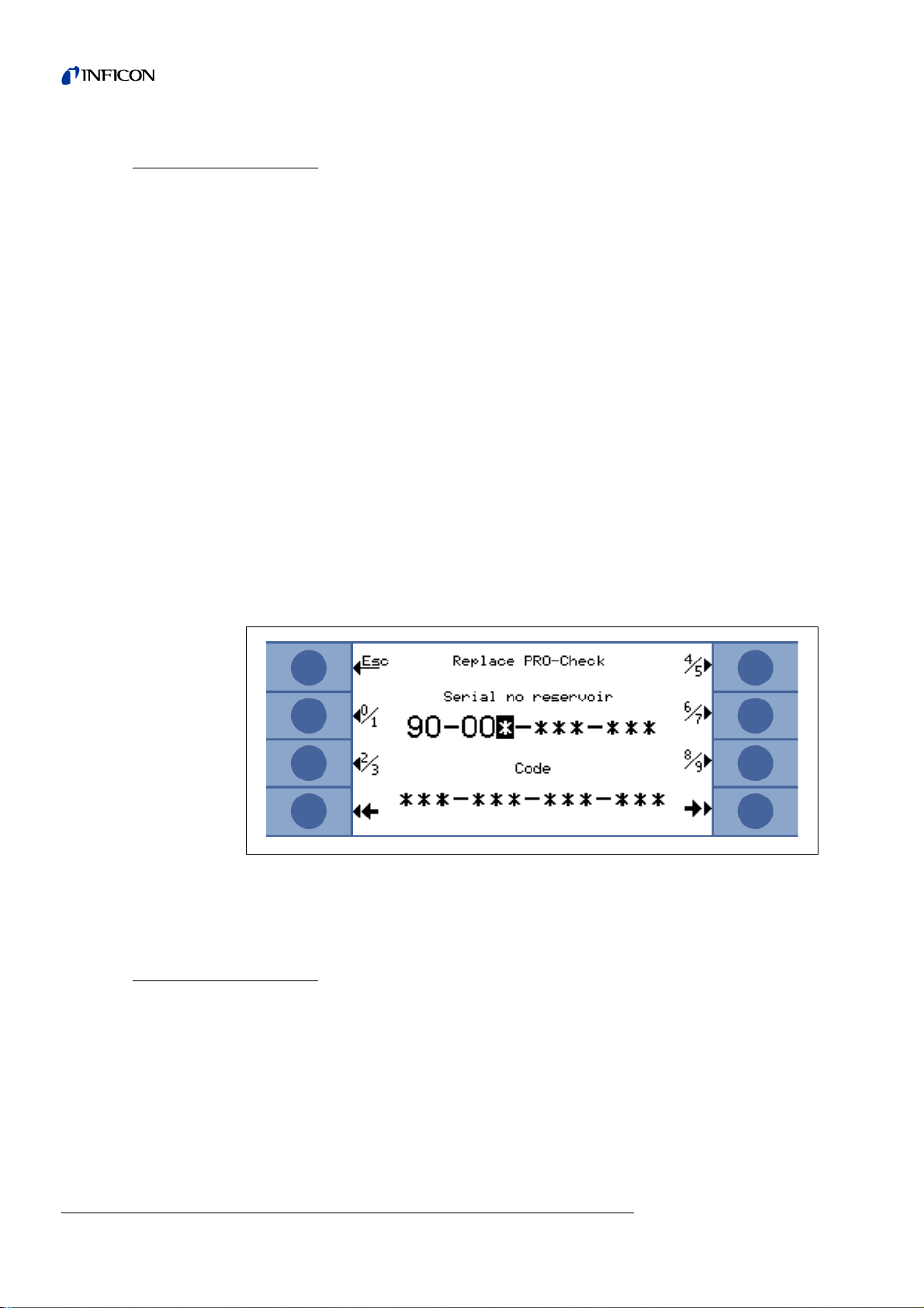
PRO-Check Reference
leak (optional)
Please insert the PRO-Check reference leak into the opening in the housing of the
main unit. Make sure that the Sub-D plug is pr operly connected with the PRO-Ch eck
leak.
Notice When properly inserted, the PRO-Check reference leak will still protrude by
On first usage of your PRO-Check you need to initialize the use of this reference leak
in the Protec P3000 software.
Please perform the following steps:
1 Insert the PRO-Check into the appropriate opening of the Protec P3000
2 In the software menu go to HISTORY & MAINTENANCE / REPLACE PRO-CHECK.
approx. 10 mm.
Notice This menu item is only available when the Protec P3000 is set to
MODE (see Section 4.4.3, Keyword: User Mode)
ADVANCED
3 On the certificate, which is delivered with the PRO-Check, you will find a serial
number and a 12-digit-code. Enter the serial number in the first line of the open
submenu and the 12-digit-code in the sec on d line an d press OK.
Notice The PRO-Check reference leak must be installed in the Protec P3000
when pressing
Fig. 1-5 Initializing the PRO-Check reference leak
OK.
Notice PRO-Check Warntime Expire Date (See Section 7.7.5).
For RC versions only
The RC version has no built-in display unit but a connectors plate is mounted instead .
Please connect the external display unit with the 5m connecting table (Cat.-no. 551-
002)
1-14 General Information
kina26e Chapter 1.fm Technical Handboook(1209)
Page 25
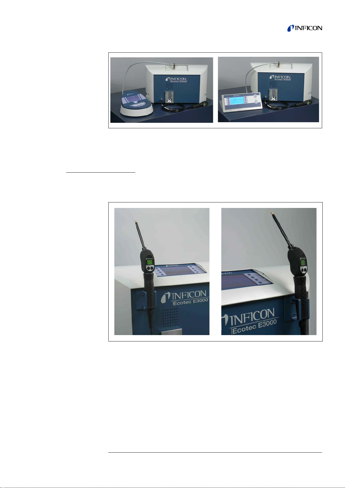
Fig. 1-6 Protec P3000 with external display unit for: (a) benchtop use (left side), (b)
rack mounting (rigth side)
Holder for SL3000
sniffer line (optional)
An optional holder for the SL3000 sniffer line is available as cat.-no. 525-006. The
holder may be installed on the right or left sid e of the main unit (for right- or left
handed operators) as shown in Fig. 1-8.
Fig. 1-7 Usage of sniffer line holder
The installation is described in Fig. 1-8. There are two little slots on the front side at
the very top area of the blue square front of the main unit. Ho ld the holder horizontally
and then insert the two little hooks of the holder into the two slots (either on the right
or the left side). With the hooks still inserted, let the holder flap down. It will
automatically attach to the metal front by the magnet on the backside of the holder.
Now insert the sniffer probe grip into the opening of the holder and let it sink down
until it rests in the holder.
kina26e Chapter 1.fm Technical Handboook(1209)
General Information 1-15
Page 26
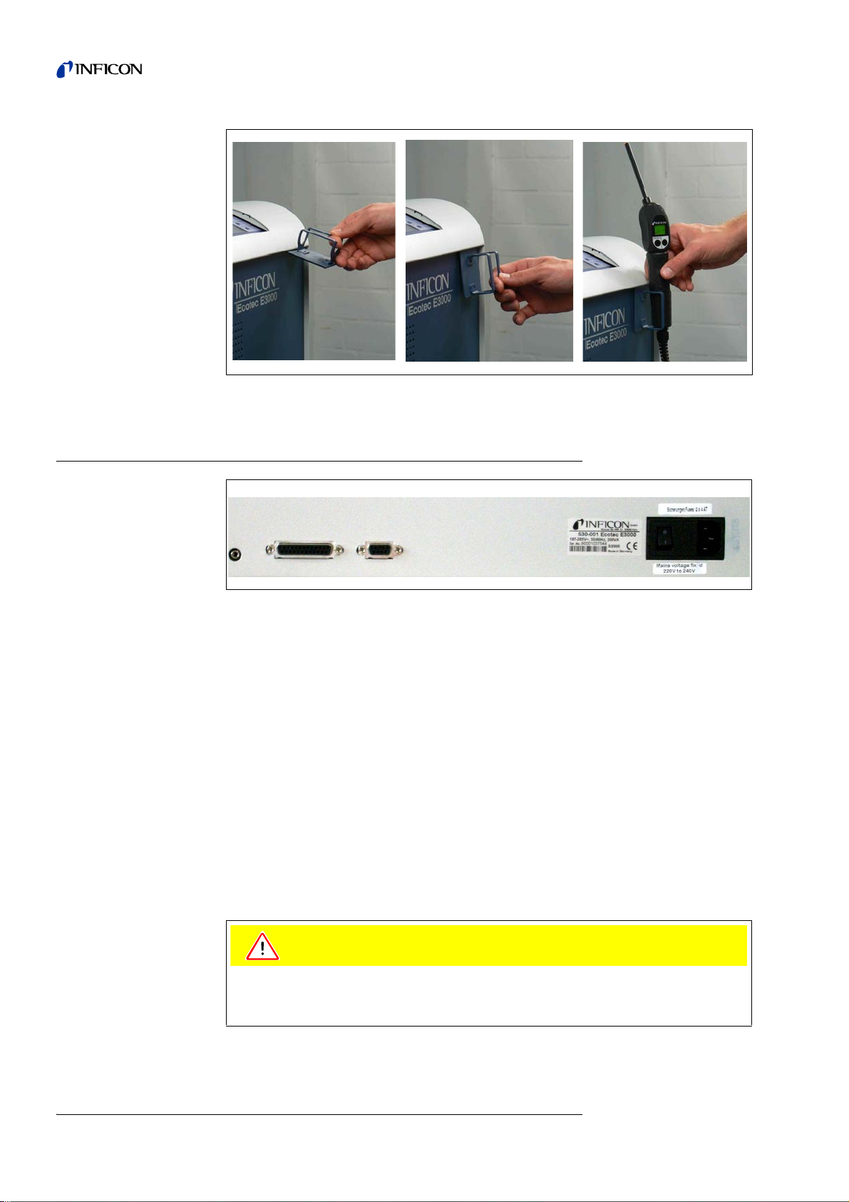
Fig. 1-8 Installation of sniffer line holder
Caution
1
23 456
1.6.3 Electri cal Conn ectio ns
Fig. 1-9 Electrical connections
Pos. Description Pos. Description
1 Headphone port 4 Name plate
2 I/O Port 5 Power switch
3 RS232 interface 6 Power connector
Notice The local regulations for electrical connections must always be observed
(in Germany VDE 0100). The mains voltage rating for the Protec P3000
can be read off from the name plate left of the power switch. The mains
voltage setting of the Protec P3000 is fixed and can not be changed. A
separate fuse for each of the mains conductors has been inte g ra te d into
the mains socket (Fig. 1-9/6).
The mains voltage is applied to the Protec P3000 via the detachable mains cable
which is supplied with the leak detector. A main power socket is available for this
purpose at the rear of the main unit.
Before connecting the Protec P3000 to the mains you must make sure that the
mains voltage rating of the Protec P3000 coincides with the locally available mains
voltage.
kina26e Chapter 1.fm Technical Handboook(1209)
1-16 General Information
Page 27

Warning
Only 3-core mains cables having a protective ground conductor must be used.
Operation of the Protec P3000 with the ground conductor unconnected is not
permissible.
1.6.4 RS232 Interface
The Protec P3000 is equipped with a RS232 interface which is located on the rear
right side of the main unit. This interface is of the DCE type (Data Communications
Equipment) and allows the connection of a PC for monitoring and data logging. The
connection is provided through a commercially available Sub-D plug. For further
information see “Interface Description Protec P3000” (kins26e1).
1.6.5 I/O Port
The I/O port allows communication with and control through external equipment via
PLC and analog data. For details see Section 6.1.
Through this connection some functions of the Protec P3000 can be controlled
externally or measurement data or the status of the Protec P3000 may be
communicated to external equipment.
Through relay changeover contacts the trigger levels as well as the operating mode
(Ready) of the Protec P3000 may be monitored.
kina26e Chapter 1.fm Technical Handboook(1209)
General Information 1-17
Page 28

2 How the Protec P3000 Works
2.1 Description of the Functions
The Protec P3000 takes in helium through the SL3000 sniffer line, detects the
amount of helium by means of a helium sensitive sensor and converts the sensor
signal into quantitative leak rates.
The Protec P3000 is composed of the following principal subassemblies:
• A Wise Technology sensor as helium detector
• A valve holder for controlling different operating stati
• A diaphragm pump for pumping the gas to the sensor
• An inlet system for the gas flow
• The correspond ing electrical and electronic subassemblies for supplying power
and for signal conditioning.
The detector operates under gross vacuum conditions, i. e. the operating pressure
at the detector is several 100 mbar. T he under pressure is generated by a diaphragm
pump. The pressure in front of the sensor is measured with a piezo-resistant
pressure gauge and is about 250 mbar under normal operating conditions.
2.2 Description of the Subassemblies
2.2.1 Backing Pump
A diaphragm pump in the Protec P3000 serves as the backing pump. All data and
further information on this pump are given in the Operating Instructions. The backing
pump generates the flow of the gas through the SL3000 sniffer line.
2.2.2 Wise TechnologyTM Sensor
The helium detector (Wise TechnologyTM sensor) consists of a closed glass
container with a measurement device for the precise determination of the pressure
inside the glass housing and a mem brane chip wit h a large nu mber of small quartz
windows. The membrane is permeable only for helium, all other components of air
are retained by the membrane and from the inside of the glass housing. The Quartz
membrane is heated so that the permeation for helium is sufficiently high and fast.
Inside of the glass housing the total pressure is measured precisely. As only helium
can enter the glass housing the total pressure is equal to the partial pressure of
helium. The determined total pressure inside the housing is proportional to the
helium partial pressure outside the sensor.
2-1 How the Protec P3000 Works
kina26e Chapter 2.fm Technical Handbook(1209)
Page 29
2.2.3 Valve Holder
The valve holder carries the valves that control the gas flow to the Wise Technology
sensor. These valves are used to select the sensitivity of the system, to activate a
protection mode against high helium contamination and to set the system into
STANDBY mode. The Protec P3000 software continuously analyses the situtation and
sets the correct valve position via the control unit.
2.2.4 Control Assembly
The control assembly (microprocessor) is the central assembly of the Protec P3000’s
electronics. All other subassemblies are controlled and monitored by this assembly.
The microprocessor which is located here is thus continuously informed about the
status of the entire Protec P3000 and can respond accordingly. In order to accept
commands from the operator and to output measured values and messages, the
control subassembly is linked to the display unit.
2.3 Description of the Displays and User
Interfaces
2.3.1 Main unit display
This subassembly is used to communicate with the operator. It accepts commands
from the 8 keys on both sides of the display and outputs measurement results and
messages via the display.
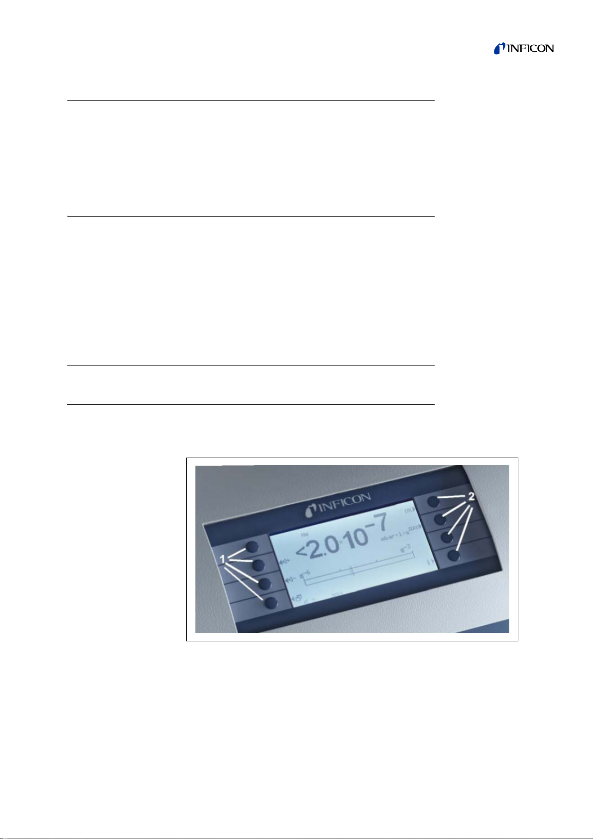
Fig. 2-1 Main unit display
Pos.Description Pos. Description
1 Menu buttons 1 to 4 2 Menu buttons 5 to 8
kina26e Chapter 2.fm Technical Handbook(1209)
How the Protec P3000 Works 2-2
Page 30
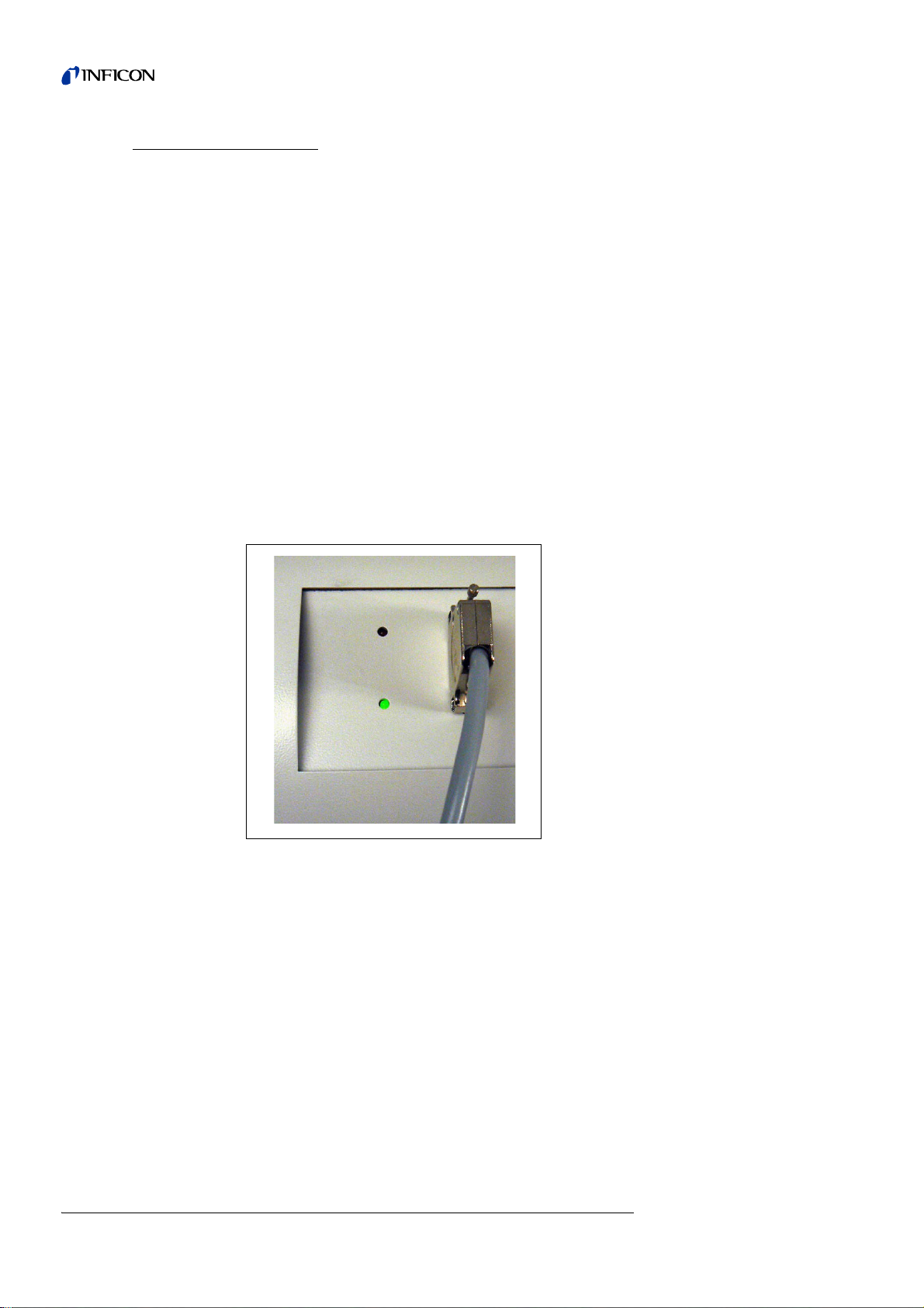
For RC versions only
The RC version has a connectors plate for the external display unit instead of the
built-in main unit display. Two LED's left of the plug provide information about the
status of the Protec P3000, even when the external display unit is disconnected:
• The green LED will indicate that the Protec P3000 is in operation (switched on).
• The red LED will be blinking in case of an error message, continuous red light
If no display unit is connected, error messages or warnings may be acknowledged
by pressing both buttons of the SL3000 sniffer line simultaneously.
The external display unit also offers four buttons:
• The START / STOP buttons have no function (the external displa y unit may also
• The MENU button will open the software menu.
• The ZERO button will set the current background reading to zero. (For details on
The green LED will show continuous green light if an external display unit is
connected and will blink if no external display unit is detected.
indicates a warning.
be used with other INFICON leak detectors which need these buttons)
the ZERO function see Section 4.4.1)
Fig. 2-2 Conncetor plate with LEDs
2-3 How the Protec P3000 Works
kina26e Chapter 2.fm Technical Handbook(1209)
Page 31

2.3.2 SL3000(XL) Sniffer line with probe display
1
3
2
The probe handle also offers a small display for operating the Protec P3000 remotely
without access to the main unit during normal leak detection operation.
1 Probe display
2 Button
3 ZERO button
Fig. 2-3 SL3000(XL)Sniffer line with probe display
In addition to the display, the sniffer probe offers two press buttons. The left button
will function as the ZERO button in any operating mode. By pressing the left button
the current background reading is set to ZERO. For details on the ZERO function see
section 4.4.1)
The right probe button is used for different functions depending on the current
operating mode the Protec P3000 is set to:
• in standard operation mode:
– no function for Protec P3000
– for Protec P3000XL: switching between
• in I•Guide mode:
– navigation through I•Guide program (for all configurations)
Fig. 2-4 Probe handle
HIGH FLOW and LOW FLOW mode
The probe handle also offers some LEDs in the flange of the sniffer tip in order to
illuminate the location currently being leak tested.
kina26e Chapter 2.fm Technical Handbook(1209)
How the Protec P3000 Works 2-4
Page 32

Warning
Do not stare into the LEDs of the sniffer line intentionally for extended times or at a
close distance as this may cause permanen t da ma g e to th e ey e.
The LEDs offer some bundled light. The intentional starring suspends the lid closing
reflex and also the eyes do not move anymore which may le ad to overhea ting of the
retina.
When looking into the LEDs „incidentally“ the eye is protected by the lid closing
reflex. Also the permanent movement of the eyes prevents overheating and
consequent damage of the retina.
2.3.3 Built-in PRO-Check reference leak
A built-in PRO-Check reference leak is available for all Protec P3000. The PROCheck reference leak can be used for verifying the correct functioning of the Protec
P3000 including the correct calibration and can also be used for re-calibrating the
Protec P3000 if necessary.
The PRO-Check reference leak is inserted in the front of the h ousing. Insertion of the
sniffer tip into the cone-shaped test leak opening is automatically detected via a light
barrier.
Fig. 2-5 Built-in PRO-Check reference leak
2-5 How the Protec P3000 Works
kina26e Chapter 2.fm Technical Handbook(1209)
Page 33

Fig. 2-6 PRO-Check reference leak detached from the main unit for remote use
1
2
In cases where the main unit is placed in a difficult or inconvenient to access area
the built-in PRO-Check reference leak can be removed from the main unit for easie r
access and connected to the main unit via the Sub-D connector with a commonly
available extension cord. The PRO-Check reference leak can then be placed in an
area where it is convenient for the operator to be reached.
Fig. 2-7 Connections for remote use
Pos. Description Pos. Description
1 Connector at built-in test leak 2 Connector at Protec P3000 housing
kina26e Chapter 2.fm Technical Handbook(1209)
How the Protec P3000 Works 2-6
Page 34

Notice The PRO-Check reference leak is not part of the Protec P3000 shipment
and needs to be ordered as a separate part no. (see section 1.3.2
Accessories).
Notice If you have not purchased the PRO-Check reference leak, warning 71 (“No
communication with test leak”) will be issued on first start-up. Please go to
SETTINGS / INTERFACES / PRO-CHECK and set the PRO-Check to “DISABLED”
to prevent future warnings (see section 4.5.6)
Notice PRO-Check Warntime Expire Date (See Section 7.7.5).
2-7 How the Protec P3000 Works
kina26e Chapter 2.fm Technical Handbook(1209)
Page 35

3 Operation of the Protec P3000
3.1 Start-Up
Assemble the Protec P3000 (see Section 1.5). Connect the mains cord and the
SL3000(XL) sniffer line, and then switch on the Protec P3000. The mains switch is
located on the rear.
Fig. 3-1 Connection of the mains cord
Pos. Description Pos. Description
1 Power Switch 2 Power cord connection
The Protec P3000 will automatically start-up without operator interaction. After power
on the message "Wait for heater" will be displayed with the pump not being started
yet. The foreline pressure as well as the flow through the sniffer line will be stated
during this time.
After the pumps are switched on a self-test procedure will be performed during which
all hardware will be checked. The message "wait for sensor current" will be displayed
next. A bar graph will indicate the progress of this warm-up stage. The expected
warm-up time left will be stated below the bar graph.
Notice The start-up procedure normally lasts 2 - 3 min. After extended times of
power off, however, the start-up of the Protec P3000 may take up to 20 min.
max. To improve the start-up behaviour of the Protec P3000 after
extended times ofpower off, see Section 3.8.
After switching on and completion of the run-up phase the Protec P3000 will be ready
to make measurements. There is no separate start function. The SL3000(XL) sniffer
lines are designed to maintain an inlet pressure low enough to make measurements.
Notice The Protec P3000 will only operate after having connected the sniffer line.
A calibration in accordance with Section 3.5 is recommended not before 20 minutes
after having switched on the instrument (warm-up phase).
kina26e Chapter 3.fm Technical Handbook(1209)
Operation of the Protec P3000 3-1
Page 36

Notice If you have not purchased the PRO-Check reference leak, warning 71 (“No
communication with test leak”) will be issued on first start-up. Please go to
Settings / Interfaces PRO-Check and set the PRO-Check to “disabled” to
prevent future warnings (see section 4.5.6).
3.2 Controls on the main display unit
All set-up and control functions are integrated into the main disp lay unit via the menu
structure. The functions of the 8 control keys are displayed on the LC display. Dur ing
measurements the main interface is the probe handle display giving all necessary
information for proper leak testing.
After start-up the Protec P3000 will automatically go into measurement mode.
Bar graph display
Fig. 3-2 Measurement screen
Pos. Description Pos.Description
1 Audio volume buttons 4 Info button
2 Menu button 5 List of gas parame ter s bu tto n s
3 Calibration button
The currently detected leak rate will be display in a bar graph in logarithmic scale.
The currently selected trigger level is indicated by a black line, the currently selected
search level is indicated by a dotted line. If the search level is exceeded the shape
of a bell is displayed at the top of the display, if the trigger is exceeded the bell starts
to blink (to ring).
3-2 Operation of the Protec P3000
kina26e Chapter 3.fm Technical Handbook(1209)
Page 37

Gas type
(refrigerant equivalent)
The currently selected gas type (helium or refrigerant equivalent) is indica ted on th e
upper left side of the display.
For P3000XL only:
If the Protec P3000XL is operated in
inverted characters (on dark background) in the main display as well on the sniffer
display.
Fig. 3-3 Measurement screen with leak
HIGH FLOW mode, the gas type is displayed in
Pos. Description
1 Selected gas type (refrigerant equivalent or He)
2 Indication of search level being exceeded
3 Indication of active warning
4 Audio volume level
5 Bar graph display of leak rate
Audio Volume Buttons
The two middle keys on the left side of the display allow to adjust the volume of the
alarm sound at any time. When pressing any of the two buttons the currently selected
volume will be demonstrated by the loudspeaker as well as by a bar graph in the
status line. The selected value is also displayed as the first entry of the status line at
the bottom of the display and only applies to the loud speaker in the main unit. For
selecting different types of alarms see section 4.4.2.
Menu Button
The button on the bottom left side of the display will open the main menu at any
time. The menu mode offers the user many possibilities of entering instrument
settings and special functions.
CAL Button
With the button on the upper right side of the display an external calibration of the
Protec P3000 can be started at any time. For details on how to perform an external
kina26e Chapter 3.fm Technical Handbook(1209)
calibration see Section 3.5.3.
Operation of the Protec P3000 3-3
Page 38

ZERO Button
When shortly pressing the zero button, the zero level will be updated. For details on
the ZERO function see Section 4.4.1.
List of gas parameters
button
Up to four different gas parameter sets can be stored in the Protec P3000. If more
than one set of gas parameters are set-up, the list button on the right side of the
display will appear in the menu screen. When pressing this button, a new set of gas
parameters (e.g. different refrigerant equivalent, different trigger level, etc) can be
selected. For details on how to set up the different gas parameters see section 4.3.1.
Info Button
Status Line
Lock Softkeys
When pressing the
status of the Protec P3000 will be displayed. For details see section 3.4.3.
In the bottom line of the main display status information is indicated. First the
currently selected volume for the audio alarm is stated. Next, a small black triangle
with an exclamation mark may indicate an active warning.
The keys C
be protected.
AL, ZERO und can be locked. So the settings of these functions can
i info button (bottom right side of the display) information on the
Abb. 3-4 Function key
3-4 Operation of the Protec P3000
kina26e Chapter 3.fm Technical Handbook(1209)
Page 39

3.3 Controls on the probe display unit
1
3
2
Warning
On the display of the probe handle similar information as on the main display is
shown.
Description
Pos.
Bar graph indicating the leak rate
1
Absolute leak rate
2
Gas equivalent
3
Fig. 3-5 Sniffer display in standard operation mode
The currently detected leak rate is indicated as a bar graph. In a second line the
numerical leak rate (in the same unit of measurement as on the main display) is
shown. In the third line the type of gas equivalent is stated (e.g. He or R134a).
For Protec P3000XL only:
If the Protec P3000XL is operated in
displayed in inverted characters (on dark background).
HIGH FLOW mode, the gas equivalent is
The sniffer probe offers two press buttons. By pressing the left button the current
background reading is set to ZERO. For details on the ZERO function please refer to
4.4.1. ZERO.
The right probe button is used for navigation when working in I•Guide mode (see
Section 3.4.2) or for starting an internal calibration (see Section 3.5.2)
3.4 Performing measurements
The Protec P3000 offers two modes of operation:
• The Standard Operation Mode (compatible to the Protec mode)
• The I•Guide Operating Mode
Danger of electric shock.
Don’t touch voltaged parts with the sniffer tip. Test samples need to be
disconnected from electricity before leak testing.
kina26e Chapter 3.fm Technical Handbook(1209)
Standby Function
The Protec P3000 offers a
contaminants into the sniffer probe during idle times, thus saving filter and sensor life
time.
STANDBY function to prevent the needless intake of
Operation of the Protec P3000 3-5
Page 40

The Protec P3000 may automatically go into standby after a preset time of
Caution
inoperation (see Chapter 4.3.1 for details on how to set-up this function) and
operation will automatically resume if the probe is picked up again.
The Protec P3000 can also be set into
probe button for 2 seconds. If the Protec P3000 has been set into
manually operation will only resume by pressing any of the two probe buttons again.
Operating in moist
environment
Do not suck in any liquids.
For operation in an environment where moisture (e.g. condensating water) may
occur, a water-protection tip is available (Cat. no. 12246) which will protect the
Protec P3000 against intake of liquids if necessary. For details on how to install the
water potection tip see 1.6.2)
Protection mode and high
helium background
STANDBY mode manually by pressing the left
STANDBY mode
The Protec P3000 is equipped with a protection mode against contamination with
huge amounts of helium. This contamination mode will help the leak detector to clean
up faster after detection of gross leaks.
If the Protec P3000 switches to
GROSS MODE the item „GROSS“ is displayed and an
acustic signal is to hear.
If a huge amount of helium is detected the Protec P3000 may show the message
HELIUM CONTAMINATED. The leak detector will come back to measurement mode
automatically after clean up and the displayed item „GROSS“ disappears.
Notice The Protec P3000 should not be switched off or set to
HELIUM CONTAMINATED is displayed as this will trap the increased levels of
STANDBY mode while
helium inside the sensor and it cannot be pumped away for clean up of the
Protec P3000. Switching off the Protec P3000 while contaminated with
large concentrations of helium will in fact lead to significantly increased
start-up times afterwards. If this has happened unintentionally, just switch
on the Protec P3000 and let it sit in "Warm up" until it reaches
measurement mode.
Notice In
HIGH FLOW mode leak rates in the range < 1x10
-5
mbar l/s are reduced
during a time of 30 Sec. to the current background value.
For details on how to set up the
CONTAMINATION LIMIT please refer to Section 4.4.1.
3.4.1 Standard Operation Mode
Provided the Protec P3000 has been set-up to meet the requirements of the
particular application and it has been calibrated (see Section 3.5), a measurement is
performed as follows:
3-6 Operation of the Protec P3000
kina26e Chapter 3.fm Technical Handbook(1209)
Page 41

First briefly operate the ZERO button on the sniffer probe. This will ensure that the
Protec P3000 eliminates all interfering influences which may affect the ZERO level
(i.e. the detection limit of 1x10
-7
mbar l/s). Next hold the tip of the sniffer as close as
possible to the suspected leak, if required the tip may even touch the te st object. If a
welded seam or alike needs to be tested, the tip should be moved at a velocity of no
more than 13 cm/s (5 inch per second) along the welded seam. The distance
between tip and test sample should be as small as possible.
If a leak is detected the bar will grow. The Protec P3000 continuously compares the
measured leak rates with the programmed trigger levels. If the trigger is exceeded
the background colour of the probe display will change from green to red. At the
same time an alarm sound will be released by the speaker in the probe handle and
the probe handle will start to slightly vibrate. As an additional indication of exceeding
the trigger value the three white LEDs in the flange of the sniffer tip will start flashing.
Fig. 3-6 Sniffer display when detecting a leak
As soon as an acoustic alarm sounds, the tip should be removed from the spot being
tested. After displaying a constant leak rate the ZERO button should be pressed
again to repeat the test. Thus, a measurement error can be prevented and the lea k
can be located.
For Protec P3000XL only:
The Protec P3000XL allows the use of the HIGH FLOW mode (requires use of
SL3000XL sniffer line). When set to HIGH FLOW mode leaks may be detected at a
larger distance from the potential leak. The high flow mode is indicated by the gas
type being displayed in inverted colors (o n the pr obe display as well as on the m ain
display). When testing for joints, the sniffer tip should be no further than 10 mm (0.4
in) away from the joint. If testing a weld ed seam (or alike), the sniffer tip should not
be moved faster than 4 cm/s (1.6 in/s) at a maximum distance of 10 mm (0.4 in) from
kina26e Chapter 3.fm Technical Handbook(1209)
the welded seam.
Operation of the Protec P3000 3-7
Page 42

If a leak is detected (and accessibility allows so) switch the Protec P3000XL to LOW
FLOW mode (by pressing the right probe button) for easier localization of the leak.
The gas type will now be displayed not-inverted. Now search for the leak again by
bringing the sniffer tip as close as po ssible to the potentially leaking area. Localize
the leak by moving the sniffer tip back and forth across the suspected ar ea. The leak
will occur where the leak rate signal shows the maximum leak rate.
3-8 Operation of the Protec P3000
kina26e Chapter 3.fm Technical Handbook(1209)
Page 43

3.4.2 I•Guide Operating Mode
The I•Guide operating mode has been introduced to suppor t the operator in applyin g
proper sniffer leak detection technique.
The I•Guide operator guiding mode allows to store pre-programmed parameters for
different units under test. The number of locations that need to be tested per
specimen, the time each location needs to be tested for as well as the time required
to move to the next location may be programmed. In add ition, a ma ximum allowab le
global leak rate for the total unit under test is stor ed. In the I•Guide mode up to 10
pre-programmed testing procedures can be stored.
Notice If the number of locations to be tested is set to zero, the Protec P3000 will
operate in a continious mode without checking for a global leak rate but still
issue the timer signal for proper testing.
3.4.2.1 Starting the I•Guide Mode
To start the I•Guide Mode go to the main menu and choose SET UP I•GUIDE. In the
opening menu go to the top line item and change the setting to
side push button and press
enabled I•Guide program in the list. A message screen will pop-up notifying the
operator that I•Guide has been activated (the gas selected in the I·Guide program
you choose).
For how to set-up and I•Guide program please refer to Section 4.4.4.
To switch back to the Standard Operation Mode select “
ON with the left hand
OK. The Protec P3000 will automatically choose the first
OFF” and press “OK”.
Fig. 3-7 Switching to I•Guide Mode
kina26e Chapter 3.fm Technical Handbook(1209)
Operation of the Protec P3000 3-9
Page 44

3.4.2.2 Selecting an I•Guide Program
To open the SELECT I•GUIDE menu press the PROGRAM LIST button on the right side
of the display.
Fig. 3-8 Measuring Screen in I•G uid e M od e
Pos. Description
1 Program list
In the opening S
and press ok. The new program is now loaded.
Fig. 3-9 Selecting an I•Guide program
3.4.2.3 Using an I•Guide Program
In the measuring screen of the I•Guide operating mode the selected program, the
gas type stored in the program as well as the summarized global leak rate will be
displayed.
ELECT I•GUIDE menu highlight the program number you intend to use
For Protec P3000XL only:
If the Protec P3000XL is operated in
inverted characters (on dark background) in the main display as well as on th e sniffer
probe display.
3-10 Operation of the Protec P3000
HIGH FLOW mode, the gas type is displayed in
kina26e Chapter 3.fm Technical Handbook(1209)
Page 45

For all Protec P3000
1
2
3
4
5
3
7
6
configurations
In the I•Guide message line the Protec P3000 will prompt the user for action. First it
will ask to move to the first testing position. Also on the probe display the message
“okay pos. 1?” will be shown. Please confirm with the right probe button that the
sniffer tip has reached the right location.
Fig. 3-10 I•Guide screens during measurement
Pos.Description
1 Selected program
2 Gas type stored in the selected program
3 I•Guide message
4 Measuring time
5 Summarized global leak rate per unit under test
6 ZERO button
7 I•Guide button
After the first location has been confirmed the message “leak check point1” will be
indicated on the main unit display and the elap sing measu rement time ( stored in the
testing program) will be shown in the lower part of the menu page. Please make sure
to hold the sniffer tip in the right testing location during the total measuring time.
During this time a ticking sound will be issued by the main unit and a beep will
indicate that the measuring time has elapsed and the sniffer tip can be moved again.
After the measurement time has elapsed the message “Move to point 2” will be
displayed on the main unit. The Probe display will read “tip to pos. 2”. Please move
the sniffer tip to the next testing location and if the wait time indicated in the display
has elapsed you may start the next measurement. If the operator tries to start the
next measurement before the wait time has elapsed, the message “please wait” will
be displayed in the message line until a next measurement is allowed. Please
confirm that the sniffer tip has been positioned properly by pressing the right probe
button so that the next measurement can be started.
kina26e Chapter 3.fm Technical Handbook(1209)
Operation of the Protec P3000 3-11
Page 46

Fig. 3-11 I•Guide screens requesting the next location
After checking the pre-programmed nu mber of location s the result of the testin g for
the total unit under test will be displayed as shown in the following screen shot. The
selected testing program as well as the gas type stored in the program will be stated
once more followed by the summarized global leak rate. If the global leak rate is
lower than the global leak rate trigger the message “Global leak check okay!” will be
displayed followed by the testing results for each tested location.
Notice For each location where no leak is detected, the currently selected lower
diplay limit is added to the global leak rate as this is the maximum leak rate
which still may occur for each position (worst case approach).
Fig. 3-12 Result of I•Guide program: unit under test passed
Pos. Description Pos. Description
1 Program na me 3 Results of each location tested
2 Gas type
If the summarized global leak rate exceeds the global trigger the message “Global
trigger exceeded!” will be displayed.
3-12 Operation of the Protec P3000
kina26e Chapter 3.fm Technical Handbook(1209)
Page 47

Fig. 3-13 Result of I•Guide program: unit under test failed
By pressing the right probe button the next testing cycle may be started.
Notice The I•Guide mode can also be used as a timer signal only. If the number of
Notice The I•Guide mode can also be used to summarize leak rates on demand.
3.4.3 The Info Page
By pressing the info button on the main display a general info page will open.
Information on the software version used, date & time information, the currently set
audio volume and the minimum audio volume are stated.
points is set to 0, the Protec P3000 will prompt for the next location to be
tested continuously without using the global leak rate function.
If the number of points is set to 99, a results screen with summarized global
leak rate will be displayed after the right button has been pressed for 2 s
conintously (or after the 98th point automatically).
Fig. 3-14 Info page without errors or warnings
If an active warning exists this will be displayed in the info page instead of the gas
info lines.
kina26e Chapter 3.fm Technical Handbook(1209)
Operation of the Protec P3000 3-13
Page 48

Fig. 3-15 Info page with active warning
When operating in I•Guide Mode, the info page will state information about the
currently selected program: the selected program name, the gas used for this
program, the number of points to be checked for this program, the selected
measuring and wait time as well as the global trigger.
3-14 Operation of the Protec P3000
kina26e Chapter 3.fm Technical Handbook(1209)
Page 49

3.5 Calibration and Self-Test
The Protec P3000 can be calibrated internally with the built-in PRO-Check re ference
leak or externally with an external calibrated leak (Cat. No. 122 37 - 122 39).
Notice If a calibration is started during the first 20 minutes after power on, a
warning will be issued.
Do not calibrate the Protec P3000 during the first 20 minutes after start-up.
Also a verification of the calibration may lead to wrong results in the first 20
minutes after start-up.
Only confirm and continue with the calibration if the real warm-up has been
longer than 20 min. (e.g. after a quick restart of the Protec P3000.)
The built-in PRO-Check reference leak can be used for a self-test of the Protec
P3000 as well as for internal calibration.
Notice The PRO-Check reference leak is a temperature compensated leak. It
must only be used when electrically connected to the main unit, either
when inserted into its port or when connected to the main unit via a Sub-D
extension cord. The leak rate printed onto the body of the PRO-Check is
only valid at 20°C (68F) and will vary greatly with temperature and time.
To compensate for this the PRO-Check reference leak is equippend with a
temperature sensor and a compensation curve is stored in the software
which automatically compensates the test leak rate for changes in
temperature when connected to the main unit.
A calibration or verification with the PRO-Check reference leak not being
connected to the main unit will cause a wrong calibration of the Protec
P3000 and / or will lead to wrong testing results.
3.5.1 Verifying a calibration (proof function)
Notice A verification can only be performed while the unit is in one of the two
measurement modes: standard operation mode or I•Guide operation
mode. A verification will not be started if the main menu is opened.
If the sniffer tip is inserted into the opening of the PRO-Check reference leak a
verification of the calibration (proof function) will be started automatically. While
holding the sniffer tip in the test leak opening, the unit will check the re ading from the
PRO-Check. Afterwards the operator will be requested to remove the sniffer tip from
the leak opening.
Notice Any time during the verification procedure an internal calibration may be
started by pressing either the right sniffer probe button or the CAL button
on the main display.
The results of the verification will be displayed in a summarizing screen. If the
verification process was successful, the message "sensitivity check OK" will be
displayed.
kina26e Chapter 3.fm Technical Handbook(1209)
Operation of the Protec P3000 3-15
Page 50

Fig. 3-16 Results of proof function for Protec P3000
If the value measured for the PRO-Check is out of range, the message "recalibration
required!" will be displayed in inverted colors.
For returning to the measuring mode, please press the right probe button or press
“
OK” on the main display.
For Protec P3000XL only
For the Protec P3000XL both calibration factors for
HIGH FLOW and LOW FLOW mode
will be verified (see fig. 3-16). However, only the information for the selected flow
mode will be relevant for passing or failing the verification. The results for the nonselected mode will be displayed for reference at the bottom of the results screen.
Fig. 3-17 Results of proof function for Protec P3000XL
3-16 Operation of the Protec P3000
kina26e Chapter 3.fm Technical Handbook(1209)
Page 51

3.5.2 Internal calibration
Notice A calibration can only be performed while the unit is in one of the two
measurement modes: standard operation mode or I•Guide operation
mode. A calibration will not be started if the main menu is opened.
If the sniffer tip is inserted into the opening of the PRO-Check reference leak with the
right probe button pressed while in measurement mode a calibration will be started
automatically. While holding the sniffer tip in the test leak opening , the Protec P3000
will measure the test leak. Afterwards the operator will be requested to remove the
sniffer tip from the leak opening.
After completion of the internal calibration a screen summarizing the results of the
calibration will be displayed. The old calibration factor as well as the new calibration
factor will be displayed. If warnings are active and have been acknowledged during
the calibration process, the message is endorsed with the information "with active
warnings".
Fig. 3-18 Results of internal calibration
To avoid unintended overwriting of a previous external (more accurate) calibration,
the operator needs to “Accept new values (anyway)?”.
3.5.3 External calibration
For external calibration it is recommended to use leak rates > 5x10⁻⁶ mbar l/s for
Protec P3000 and leak rates of > 5x10
P3000XL at
HIGH FLOW (3000 sccm).
If the reference leak rate is < 5x10
calibrates in
LOW FLOW mode.
Notice If significantly increased backgrounds are prevalent in your production
environment, larger leak rates for the calibration leak may be required.
The external calibration is a semi-automatic process during which the user will have
to follow some instructions. The calibration process may be starte d via the “
button from the measuring mode at any time (except when the menu is open or the
function has been locked). A running calibration process may be cancelled by
operating the “
kina26e Chapter 3.fm Technical Handbook(1209)
ESC” button.
-5
mbar l/s when calibrating the Protec
-5
mbar l/s the Protec P3000XL automatically
CAL” -
Operation of the Protec P3000 3-17
Page 52

After pressing the CAL button, please check whether the leak rate equals the leak rate
of the external leak you plan to use. If the leak rate is different press
EDIT LEAK RATE
and enter the correct leak rate value. Press “START” afterwards to begin with the
calibration process.
Fig. 3-19 Setting-up the leak rate of the external leak
Please hold the sniffer tip to the outlet of the external calibrated leak. Hold the sniffer
tip steady and very close to the opening, however, do not clog the opening with the
sniffer tip. Some air also needs to enter the sniffer tip in addition to the helium from
the external calibrated leak. If the leak rate signal indicated by the bar graph is stable
press “
OK”. Keep holding the sniffer tip steady in front of the opening while the Protec
P3000 reads the leak rate of the calibrated leak. During this time the text “Please
wait…” will be displayed.
Fig. 3-20 Calibration screen during external calibration
When the analysis of the calibrated leak signal is completed a message “sniff air!”
will be displayed. Remove the sniffer tip from the opening of the calibrated leak and
hold the sniffer tip into the air, as far as possible from any sources of helium. Wait
until the bar graph shows a stable signal again and press “ok” once more.
3-18 Operation of the Protec P3000
kina26e Chapter 3.fm Technical Handbook(1209)
Page 53

Fig. 3-21 Request to sniff air during external calibration
A message “Please wait…” will be displayed until the calibration is finished.
After completion of the external calibration a screen summarizing the results of the
calibration will be displayed. The old calibration factor as well as the new calibration
factor will be displayed. If warnings are active and have been acknowledged during
the calibration process, the message is endorsed with the information "with active
warnings".
Fig. 3-22 Results of external calibration
kina26e Chapter 3.fm Technical Handbook(1209)
Operation of the Protec P3000 3-19
Page 54

3.6 Standby
If not used, the Protec P3000 will go into a STANDBY mode automatically after a
predetermined time in order to avoid wear of parts during times not used. In this
STANDBY mode the flow through the sniffer line will be shut down to conserve filters
in the sniffer line as well as to save sensor life time.
If the operator picks up the sniffer line, a movement sensor will detect this action and
will set the Protec P3000 back into normal operation. The Protec P3000 will be ready
for measurement again after approx. 5 seconds.
For details on how to set the time until the Protec P3000 goes into
please refer to section 4.3.1 (
VACUUM & ACCESS, STANDBY DELAY)
3.7 Shutdown
To shut down the Protec P3000, set the ON / OFF main switch (Fig. 3-1/6) to the „0“
position regardless of the operating mode of the Protec P3000. Nothing else is
required. The parameters entered are saved by Protec P3000. After switching on, the
Protec P3000 will revert to the same status it was in when it was switched off before.
3.8 Storage for fast availability as back-up unit
STANDBY mode
Due to accumulation of Helium (from air) in the sensor unit during storage the startup time for the Protec P3000 will be approx. 1.5 min per day of storage with a
maximum start-up time of approx. 1 hour.
If you want to use the Protec P3000 as a back-up unit to ensure uninterrupted
availability of your production line, the Protec P3000 should be stored as follows.
1 Shut down the Protec P3000 but keep it connected to a power outlet.
2 Put a clock timer between the Protec P3000 and the power outlet.
3 Program the clock timer to switch on the Protec P3000 for 1 hour twice per week (at
least every 4 days).
Notice The clock timer should be battery buffered so that in case of a loss of power
in the factory, the clock timer does not loose its pre-programmed window
for power on.
With this approach the max. start-up time will be approx. 7 min.
3-20 Operation of the Protec P3000
kina26e Chapter 3.fm Technical Handbook(1209)
Page 55

kina26e Chapter 3.fm Technical Handbook(1209)
Operation of the Protec P3000 3-21
Page 56

4 Equipment Settings
4.1 Menu Structure
By pressing the menu button the main menu page opens. The following options will
be displayed:
Fig. 4-1 Main menu screen
In the subsequent sub-menus the following frequently used functions will occur:
↑ ↓ The “up” and “down” keys allow scrolling through listed menu items. The
currently selected menu item is highlighted by inverted colours. The “up”
and “down” keys are also used for changing numerical values to a new
setting.
? Help function – by pressing this key additional information on how to use
this page can be displayed.
Esc Going back to the pre viou s pa ge while om ittin g any cha n ge s.
Back Going back to the next higher level in the menu structure.
OK Accepting a selected item from a list or accepting newly entered values.
Exit all menus and return to main screen. If the menu button is presse d later
on again, the software will jump to the menu page that has been exited by
the button. By pressing the back key the display will go back one level
and finally all the way back to the measurement display page.
The menu structure of the main menu is illustrated on the following page for quick
reference.
4-1 Equipment Settings
kina26e Chapter 4.fm Technical Handbook(1209)
Page 57

Main menu Standby/Start Library Gas
Service User Gas
Gas Trigger Gas 1 Name (edit) Helium
Gas 2 Additional He
Gas 3 M ode
Gas 4 Trigger&U nit
Display limit
Search level
Equivalent correction (He)
Settings Vakuum & access Zero time
Contamination limit
Flow limits (only P3000) limit LOW FLOW
limit HIGH FLOW
Flow settings (only P3000XL) Additional low flow error
Flow mode
Li mi ts l ow flow e rr or
Sn i ffe r bu tton
Standby delay
CALibration
Change menu-PIN
Audio Beep sound
Au dio intern
Audio Sn i ffer
Al arm typ e
Vo lume
Setup I-Guide I-Guide ON/OFF
M e a s . 1. .. 10 ( e d i t ) N a m e
Gas
No. of p oints
Measuring time
Wait time
Global trigger
Misc ellaneo us Language
Time & d ate
PRO-Check Warntime Expiry Date
Pressure u n it
Leak rate filter
Al arm delay
Sn i ffe r li g h t
Display Contrast
Pe ak h old
Flow Displa y (1)
User mode
Lock Softkey s
Interfaces Control location
Recorde r out p u ts
Select PLC inputs
RS232 protocol
Baud rate & End sign
PRO-Check
e
View error list
Calibration history
Sn i ffe r ti p fi l te r
Maintenance intervall
Maintenance history
Confirm maintenance (1) (1) only in user mode "Advanced mode"
Replace PRO-Check (1)
Info General data
Sensor Global
Sensor Errors
PRO-Check data
Sniffer line data
I/O-P o rt data
Analog data
kina26e Chapter 4.fm Technical Handbook(1209)
History&M aintenanc
Equipment Settings 4-2
Page 58

4.2 The Service Menu
The service menu is password protected. When entering the service menu a PIN is
required to be entered. The service menu should only be used by trained service
personnel. The PIN for entering the service menu will be distributed during service
training. Please refer to the service documentation for the submenus and functions
of the service menu.
4.3 Selecting gas equivalents and setting trigger
values
The Protec P3000 can detect leak rates as helium leak rates or in refrigerant
equivalent leak rates. Up to four different sets of parameters can be stored by the
Protec P3000. Only one type of leak rate, however, will be displayed in the
measurement screen optional with the equiva lent Helium leak rate in addition. In the
gas / trigger menu the chosen gas equivalen ts are displayed with their curr ent trigger
value.
With default settings only helium is set up in the first set of parameters. The
remaining three sets are blank ("<------>"). Only sets that have been edited will be
listed in the list of gas parameters that can be loaded directly from the measuring
screen through the list button.
4.3.1 Setting gas parameters
When pressing one of the GAS1 to GAS4 buttons an info page regarding the chosen
set of parameters will open. Parameter sets that are not in use are marked blank
(„<----->)“. Changes to the current setting can be made by scrolling to the line item to
be changed by use of the
the
EDIT key.
Fig. 4-2 Editing Gas 1
In the opening info page the name of the gas equivalent (or helium), the
measurement mode and the currently selected trigger value will be displayed. This
info is followed by the value for the lower display limit. In addition, the correction
factor, the helium concentration used, the fill pressure for helium and the fill pressure
for refrigerant later on are listed.
UP and DOWN keys and selecting the line item by pressing
kina26e Chapter 4.fm Technical Handbook(1209)
4-3 Equipment Settings
Page 59

Name
(Gas equivalent)
Additional Helium
For displaying the leak rate in refrigerant equivalent leak rates go to the
menu and go to the
SELECTION
submenu choose the refrigerant equivalent from the GAS LIBRARY. Gas
NAME line item. Press the EDIT button and in the opening GAS
EDIT GAS sub
parameters can be fully deleted by setting the gas name back to blank („<----->“).
Notice If more than one set of parameter is set up (i.e. maximum two gases are
not named „<----->“) a list button will appear on the right side of the
measurement screen. When pressing the list button a short-cut to selecting
the different parameter sets will be provided.
This submenu only is available when operating in gas equivalents. In this case the
Protec P3000 may display the Helium leak rate in addition to the refrigerant
equivalent leak rate in the main measurement screen. This feature may be selected
or not selected.
Default: not selected
Fig. 4-3 Selecting additional Helium
Notice The option “Additional He” is only available if at least one parameter set
(gas 1 … gas 4) is configured to helium.
The additional helium will be displayed in the unit of measurement of the
lowest gas number set to helium.
kina26e Chapter 4.fm Technical Handbook(1209)
Equipment Settings 4-4
Page 60

Editing gas equivalent
parameters
Fig. 4-4 Selecting gases from the library
Back in the edit gas submenu scroll to the
EDIT.
HELIUM PERCENTAGE line item and press
Fig. 4-5 Setting a refrigerant equivalent correction factor
In the opening submenu the helium fill pressure, the fill pressure for the gas
equivalent (refrigerant) later on and the concentration of helium used can be entered.
In the lower right corner the
CORRECTION FACTOR (from helium to refrigerant) will be
displayed. If a set of parameters is entered that exceeds the boundaries of the Protec
P3000 the correction factor will be displayed in inverted colours. In this case adjust
the parameters until the correction factor is displayed in normal colours again . Press
OK if all parameters are as desired.
4-5 Equipment Settings
Notice This menu should also be used when working with diluted Helium but still
displaying the leak rate as a Helium leak rate.
Notice This menu should be used at any time when the Helium fill pressure in pre-
testing differs from the refrigerant fill pressure later on to display the correct
leak rate value, even if the leak rate is still displayed as a Helium leak rate.
kina26e Chapter 4.fm Technical Handbook(1209)
Page 61

Fig. 4-6 Editing parameters for refrigerant equivalent leak rates
In the EDIT GAS submenu you can now enter the TRIGGER value in the refrigerant
equivalent value.
A set of parameters (refrigerant type, fill pressure, helium concentration) can also be
saved as user gas.
In the measurement screen the gas type will now be displayed as refrigerant
equivalent leak rate (e.g. R134a <- He).
Trigger and unit of
measurement
In the
the corresponding line item. You can change the trigger level setting by the use of
the left
You can leave the submenu without making any changes by using the
EDIT GAS X info page the TRIGGER & UNIT sub-menu page will open by selecting
UP and DOWN keys. The correct settings must be confirmed by the OK button.
ESC key.
The leak rate unit can be changed by the use of the right
Available leak rate units include mbar l/s, Pam
3
/s, Torr l/s, atm cc/s, g/a, oz/yr,
UP and DOWN keys,
lb/yr, ppm.
Default value: 2 x 10
-5
mbar l/s
Fig. 4-7 Setting-up trigger level and unit of measurement
Pos. Description Pos. Description
1 Increasing the trigger value 3 Changing the unit of measurement
kina26e Chapter 4.fm Technical Handbook(1209)
2 Decreasing the trigger value 4 Changing the unit of measurement
Equipment Settings 4-6
Page 62

Display limit
Fig. 4-8 Editing the lower display limit
The lower display limit for each gas can be edited. To change the lower display limit
go to the “
DISPLAY LIMIT” line item in the “EDIT GAS” submenu and press “EDIT”. The
lower display limit can be increased in factors of the lowest display limit. In the line
below the factor the absolute lower display limit in the currently chosen unit of
measurement is stated. Available factors are 1, 2, 5, 10, 20, 50, 100.
For the Protec P3000XL the lowest display limit of 1x10
-6
mbar l/s equals factor 1.
The equivalent absolute lower display limits at other factors are the lower display limit
in
LOW FLOW mode mulitplied by a factor of 10.
Notice For Protec P3000XL only:
When switching from
display limit factor will remain unchanged, i.e. if the lower display limit factor
is set to 2, the lower display limit will be adopted from 2x10
-6
1x10
mbar l/s automatically when switching from LOW FLOW to HIGH FLOW.
Default value: 2
Search level
An additional warning level can be entered as percentage of the trigger level. A
warning signal will be issued for leaks that are below the trigger level but above the
search level in order not to miss small leaks. The search level may be set to values
between 5 and 100%. Default value: 90%
4.3.2 Selecting a set of gas parameters
A set of gas parameters can be selected by setting the Mode in the Gas Edit menu
to “enabled”. Enabling a set of parameters will automatically disable all other three
sets of parameters so that only one set of parameters is used at the time.
LOW FLOW to HIGH FLOW (or vice versa) the lower
-7
mbar l/s to
4-7 Equipment Settings
kina26e Chapter 4.fm Technical Handbook(1209)
Page 63

4.4 Settings Sub-menu
In the settings sub-menu several settings which are important for the leak testing
procedure can be edited.
4.4.1 Vacuum & Access
In the Vacuum Access sub-menu setting monitoring functions like the ZERO function,
the flow limits and the contamination limit setting can be edited.
Zero time
The
ZERO function is automatically updated when the backgr ound decre ases so that
negative values will never be displayed, thus avoiding unintended missing of leaks.
The
ZERO TIME is the time the leak rate has to be negative in order for the Protec
P3000 to update the background level. The
1.0 and 9.9 s.
Default value: 5.0 s
Contamination Limit
The Protec P3000 offers a protection mode against high helium concentrations
(contamination with helium).
This feature should be used to prevent the sensor from accelerated aging when
seeing large helium concentrations very frequently. The
set to levels of
accumulated amount of helium sniffed over the last couple of seconds. If this
accumulated amount of helium exceeds the preset level (
message „contaminated“ will be displayed until the amount of helium in the system
has decreased again sufficiently. However, the lower the
the smaller the largest possibly detected leak will be.
ZERO TIME can be set to values between
CONTAMINATION LIMIT can be
LOW, NORMAL AND HIGH. The contamination limit function will track the
LOW, NORMAL, HIGH) the
CONTAMINATION LIMIT set ting
Notice You should start with the
CONTAMINATION LIMIT set to LOW. If you feel that
you get the „contaminated“ message too often, you may increase the
CONTAMINATION LIMIT by one level at a time (to get the best usage out of
your Wise Technology Sensor).
Default: N
ORMAL
The lower the contamination limit is set, the longer the life time of the Wise
Technology sensor of the Protec P3000.
kina26e Chapter 4.fm Technical Handbook(1209)
Equipment Settings 4-8
Page 64

Fig. 4-9 Setting up the contamination limit
Notice The Protec P3000 should not be switched off or set to STANDBY mode while
Flow limits
(for Protec P3000 only)
In this submenu the minimum and maximum gas flow through the capillary is
entered. If the actual gas flow drops below this limit (e.g. if the capillary becomes
partially blocked) or exceeds this limit (e.g. if the sniffer line is damaged so that
ambient air is sucked in) a n a l arm is issued. The closer the
to the actual gas flow the more sensitive the Protec P3000 will respond to beginning
clogging of the filters and the sniffer lin e itself. The closer the
to the actual gas flow the more sensitive the Protec P3000 will respond to damages
to the sniffer line.
Notice The flow through the sniffer line depends on the atmospheric pressure. If
The
LOWER FLOW LIMIT can be set to values between 150 and 240 sccm. Default
value is 180. The
default value of 350.
HELIUM CONTAMINATED as this will trap the increased levels of helium inside
the sensor and it cannot be pumped away for cle an up of the Protec P3000.
Switching of the Protec P3000 while contaminated with large
concentrations of helium will in fact lead to significantly increased start-up
times afterwards. If this has happened by mistake, just switch on the Protec
P3000 and let it sit in "Warm up" until it reaches measurement mode.
LOWER FLOW LIMIT is set
UPPER FLOW LIMIT is set
operated at high altitude the flow through the sniffer line may drop
significantly (approx. 20% per 1000 m altitude). In this case, please adjust
the flow limits accordingly.
UPPER FLOW LIMIT can be varied between 300 and 650 with a factory
4-9 Equipment Settings
kina26e Chapter 4.fm Technical Handbook(1209)
Page 65

Fig. 4-10 Changing the flow limits of the SL3000 sniffer line
Flow settings
(For Protec P3000XL only)
The Protec P3000XL can be used in
LOW FLOW mode as well as in HIGH FLOW mode.
In the flow settings submenu all settings related to both flow modes can be adjusted.
When entering the
FLOW SETTINGS submenu four further submenus will be displayed:
Fig. 4-11 Setting up flow settings
Flow limits
LOW FLOW
In this submenu the UPPER FLOW LIMIT and LOWER FLOW LIMIT for the LOW FLOW mode
may be set-up. The
LOWER FLOW LIMIT can be set to values between 150 and 240
sccm. Default value: 180
The
UPPER FLOW LIMIT can be varied be tween 300 and 650 sccm. Defaul t value: 395
kina26e Chapter 4.fm Technical Handbook(1209)
Equipment Settings 4-10
Page 66

Flow limits HIGH FLOW
Fig. 4-12 Variation of flow limits
In this submenu the UPPER FLOW LIMIT and LOWER FLOW LIMIT for the HIGH FLOW mode
may be set-up. The
LOWER FLOW LIMIT can be set to values between 1500 and 2400
sccm. Default value: 1800
The
UPPER FLOW LIMIT can be varied between 3000 and 3990 sccm.
Default value: 3950
Notice To be able to measure in H
is equipped with two capillaries (~300sccm and ~2700 sccm). In L
mode only the smaller capillary is used, in H
IGH FLOW and LOW FLOW mode, the SL3000XL
OW FLOW
IGH FLOW mode both are used,
but only the gas from the smaller one is directed to the Wise Technology
sensor.
To monitor the correct flow through the smaller capillary in
(if blocked, no leaks are detected any more), the flow limits in H
mode are converted into corresponding
Technology sensor. If these
PRESSURE LIMITS are exceeded or undercut,
PRESSURE LIMITS at the Wise
HIGH FLOW mode
IGH FLOW
this is an indication of the smaller capillary’s flow being out of the normal
range and a warning message (W41 or W42) is issued.
Additional low flow error (only available in ADVANCED mode)
Notice This submenu is only available when in
ADVANCED mode and if a SL3000XL
sniffer line is connected to a Protec P3000XL main unit.
In this submenu an
ENABLED an additional flow error (E55 / E56) will be issued in addition to the standard
low flow warnings. Only if the
LIMITS LOW FLOW ERROR will be available.
If a
LOW FLOW ERROR occurs, the Protec P3000XL will stop measuring. Only when the
cause of the low flow problem has been resolved and the flow is above the
ERROR again, the Protec P3000XL will go back into measurement mode.
FLOW
ADDITIONAL LOW FLOW ERROR may be ENABLED or DISABLED. If
ADDITIONAL LOW FLOW ERROR is ENABLED, the button
LIMITS LOW
4-11 Equipment Settings
The
LIMITS for the LOW FLOW ERROR may be set -up in the LIMITS LOW FLOW ERROR
submenu (see below).
Default setting: disabled
kina26e Chapter 4.fm Technical Handbook(1209)
Page 67

Flow mode (only available when SL3000XL sniffer line is connected)
In this submenu the Protec P3000XL can be switched between
HIGH FLOW mode.
LOW FLOW mode and
Default setting:
HIGH FLOW Mode
Limits low flow error
This submenu is only available if the
In this submenu the limits for the
actual flow through the sniffer line drops below the
ADDITIONAL LOW FLOW ERROR is set to ENABLED.
ADDITIONAL LOW FLOW ERROR may be set-up. If the
LIMITS LOW FLOW ERROR, the
Protec P3000XL will stop measuring. Only when the cause of the low flow problem
has been resolved and the flow is above the
LIMITS LOW FLOW ERROR again, the
Protec P3000XL will go back into measurement mode.
Fig. 4-13 Additional limits for low flow error
Two different values for the HIGH FLOW and LOW FLOW mode may be entered.
The value for the HIGH FLOW mode will also be converted into a corresponding
LOWER PRESSURE LIMIT. If the corresponding LOWER PRESSURE LIMIT is
undercut, this is an indication of the smaller capillary's flow being blocked in
SL3000XL sniffer line and also E55 / E56 will be issued and the Protec P3000XL will
stop measuring.
Error limits can be set to values between 150 and 240 sccm for LOW FLOW mode
and to values between 1500 and 2400 sccm for HIGH FLOW mode.
Default value: 150 sccm for LOW FLOW mode
1500 sccm for HIGH FLOW mode
Sniffer button
In this submenu the use of the right sniffer button for switching between
LOW FLOW
and HIGH FLOW mode during leak testing (except when in I·Guide mode) may be
ENABLED or DISABLED. If the use of the SNIFFER BUTTON is DISABLED, the Protec
P3000XL may only be switched from
through the
FLOW MODE submenu or via RS232.
HIGH FLOW to LOW FLOW mode (or vice versa)
Default setting: enabled
kina26e Chapter 4.fm Technical Handbook(1209)
Equipment Settings 4-12
Page 68

Standby Delay
Cal
The Protec P3000 offers a
times when the Protec P3000 is not used. During the
STANDBY mode to preserve filters and sensor life time in
STANDBY mode the flow through
the sniffer line will be stopped, thus no dirt is pumped through the filters and the
sensor is not subjected to the helium background presented in the testing
environment.
The time until the Protec P3000 goes into
STANDBY DELAY time. The STANDBY delay time can be set to values between 10 s and
1 h. If the probe is not moved for the set
switch to
STANDBY mode automatically. If the probe is moved during this time, the
STANDBY mode is determined by the
STANDBY delay time the Protec P3000 will
counter will be set back to zero and start again.
If the probe is picked up when the Protec P3000 is already in
STANDBY mode the
Protec P3000 will go back into operation automatically and will be ready for
measurement again in approx. 5 sec.
Default value: 10 min.
Notice It is recommended to keep the
STANDBY delay time as short as possible to
minimize wear of the systems without causing too much interruption of your
operations.
In the CALibration submenu an internal calibration can be
function is set to
DISABLED, only a proof function with the built-in PRO-Check
ENABLED or DISABLED. If the
reference leak will be possible.
Default value:
ENABLED
Change menu PIN
Any changes to the current settings may be password protected. The menu PIN can
be changed in the “change menu PIN” submenu.
Fig. 4-14 Setting-up a Menu-PIN for paramete r pr ot ec tion
If a new PIN is entered the Protec P3000 software will ask to repeat the new PIN to
prevent entering errors. Afterwards the menu PIN will be changed to the new value.
kina26e Chapter 4.fm Technical Handbook(1209)
4-13 Equipment Settings
Page 69

Notice The operator needs to go back up through the main menu for this change
to become effective immediately. Otherwise, the new PIN will be activated
after 5 minutes.
A menu PIN of “0000” means no password protection, all menus can be freely
accessed.
Default setting: 0000
kina26e Chapter 4.fm Technical Handbook(1209)
Equipment Settings 4-14
Page 70

4.4.2 Audio Functions
In the Audio sub-menu all settings regarding the different audio alarms of the Protec
P3000 can be edited.
Beep sound
Beep sounds are sounds that are issued as confirmation of certain functions, e.g.
completion of a calibration process. This acknowledgement sounds can be enabled
or disabled in the beep sound submenu.
Default value: enabled.
Audio intern
The internal loudspeaker of the main unit can be switched on and off. This will not
effect the headphones outlet.
Default value: enabled.
Audio sniffer
Alarm type
The loudspeaker of the probe handle can be set to issue an alarm when the
TRIGGER
level is exceeded, when the SEARCH level is exceeded or can be disabled completely.
Default value:
TRIGGER.
Different types of audio alarm of the main un it speaker can be selected. Optio ns are
SETPOINT, PINPOINT, and TRIGGER ALARM.
SETPOINT The frequency of the tone will change when the trigger level is
exceeded. Below the trigger level the loudspeaker will remain off.
TRIGGER
ALARM
An acoustic alarm with a continuous low tone will sound as soon as
the search level is exceeded. An acoustic alarm which consists of
two tones sounds as soon as the trigger level is exceeded. Below the
search level the loudspeaker will remain off.
If the Protec P3000 is set to TRIGGER ALARM as the alarm type an
additional button will be shown on the lower right side called TONE
1,2,3. With this button different alarm sounds can be selected for the
trigger alarm to clearly distinguish between nearby other leak
detectors.
PINPOINT The external loudspeaker is always on. Within the leak rate range of
+/- one decade of the trigger level the frequency will change
depending on the leak rate. Outside this range the tone will be
constantly low or high. This setting is recommended if also leaks
which are still below the trigger level need to be pinpointed or if the
expected leak rates are within the range of the trigger level.
4-15 Equipment Settings
Default value: Trigger Alarm
kina26e Chapter 4.fm Technical Handbook(1209)
Page 71

Volume
The
MINIMUM VOLUME and the currently selected VOLUME for the loudspeaker in the
main unit can be edited. The
MINIMUM VOLUME is the lowest level the volume can be
set to from the main display and should prevent unintentional turning off of the main
unit audio alarms. Both values will also be valid for the headphones outlet. Both
volumes (minimum and current) can be chosen between 0 and 15.
Default value for minimum volume: 2
Default value for the current volume: 2.
kina26e Chapter 4.fm Technical Handbook(1209)
Equipment Settings 4-16
Page 72

4.4.3 Display Settings
In the DISPLAY SETTINGS submenu the contrast of the display can be changed and the
peak hold function can be set-up.
Contrast
In the
CONTRAST submenu the contrast of the main unit display can be adjusted.
Values between 0 and 99 can be entered. Also the display can be switched to
inverted colours.
Default value: not inverted, Level 30
Notice If by accident the display contrast has been set too high or too low so that
it cannot be read off anymore, this can be fixed as follows: Shut off the
Protec P3000 and switch it back on. During run-up press the third button
from the top on both sides of the display simultaneously until the contrast
is back to normal. This setting is not saved to the EEPROM but needs to
be confirmed manually through the contrast menu. Otherwise the Protec
P3000 will go back to the out of range setting after the next start-up.
Peak hold
Fig. 4-15 Setting-up the contrast of the main dis play
The
PEAK HOLD function can be enabled or disabled in this submenu. If the PEAK HOLD
function is enable the maximum leak rate will be displayed for a preset time in
addition to the currently me asured value in the main display. Th e time setting will
have no effect if this function is disabled.
Default: value disabled, 5 s.
kina26e Chapter 4.fm Technical Handbook(1209)
4-17 Equipment Settings
Page 73

Fig. 4-16 Setting-up the peak hold function
Flow display (only available
in ADVANCED mode)
In the
FLOW DISPLAY submenu the continuous display of the flow through the sniffer
line during measurement s can be
indicated in the
as integer number.
Notice After certain events like acknowledging warnings or when switching the
Default setting: disabled
User mode
In this submenu either the
NORMAL mode only the most relevant information for normal operation will be
displayed whereas in the
will become available.
ENABLED or DISABLED. If ENABLED, the flow will be
STANDARD OPERATION MODE only underneath the leak rate bar graph
flow mode, the flow monitoring may be disabled for a short period of time
while the flow stabilizes to a final value again and no new warnings will be
issued. During this time a message ”Flow control inactive” will be displayed
instead of the flow value.
NORMAL or the ADVANCED mode can be selected. In the
ADVANCED mode additional information for advanced users
kina26e Chapter 4.fm Technical Handbook(1209)
Equipment Settings 4-18
Page 74

4.4.4 Setting-up / editing an I•Guide Program
When selecting the SETUP PROGRAM button a submenu page will open showing the
list of 10 pre-programmable I•Guide programs and their current status (enabled /
disabled). If a program is enabled it will be offered in the list of programs to select
from when operating in the I•Guide mode. To change the status of a program use the
ON / OFF button on the left side of the display.
Fig. 4-17 Setting-up the I•Guide Mode
To edit the parameters of a program select the program by scrolling to the
corresponding menu line and open the selected program by pressing the “E
button.
DIT”
4-19 Equipment Settings
Fig. 4-18 Editing an I•Guide program
In the opening
EDIT PROGRAM sub-menu the name of the program, the gas type
selected for this program, the number of locat ions to be leak tested, the minimum
measuring time for each location as well as the wait time between two leak tests
allowed for moving the sniffer to the next location is stated. In addition, the
summarized global trigger value corresponding to the allowable leak rate for the
complete unit under test is stored.
Each parameter can be edited by scrolling to the appropriate line item and selecting
the highlighted item by pressing the
EDIT button.
kina26e Chapter 4.fm Technical Handbook(1209)
Page 75

Name
Gas type
Each program can be named with a free text, descriptive name up to 6 characters.
The name can be edited by highlighting the name line and pressing
EDIT. An
alphanumerical entry screen will open. Press ok after entering the desired name
description.
No. of points
For editing the gas equivalent go to the “
equivalents that are listed in the “
GAS” line item and press “EDIT”. Only gas
GAS/TRIGGER” submenu (Gas1 to Gas4) are
available for selection. The gas equivalent is sta ted in plain text in pa renthesis. Th e
list of maximum four available gas equivalent can be scrolled with the up and down
buttons.
Notice The I•Guide Mode refers to the gas equivalent selected in the “
TRIGGER” submenu. If you change a gas equivalent in the “GAS” submenu
GAS/
the gas equivalent selected for the I•Guide program will automatically
change as well.
The number of potential leak locations to be checked can be varied between 0 and
99 and can be edited with the up and down keys.
Default value: 4
Notice The I•Guide mode can also be used as a timer signal only. If the number of
points is set to 0, the Protec P3000 will prompt for the next location to be
tested continuously without using the global leak rate function.
Notice The I•Guide mode can also be used to summarize leak rates on demand.
If the number of points is set to 99, a results screen with summarized global
leak rate will be displayed after the right button has been pressed for 2 s
continiously (or after the 98th point automatically).
Measuring time
The
MEASURING TIME during which the sniffer tip needs to be hold to the correct
location can be programmed to values between 0.7 and 25.0 s. The measuring time
should not be less than the response time of the Protec P3000. We recommend to
use the following minimum measuring times:
Sniffer line length min. measuring time
3m 0.7 s
5m 0.9 s
10m 1.4 s
15m 3.0 s
Please use the
kina26e Chapter 4.fm Technical Handbook(1209)
Default value: 1.0 s
UP and DOWN buttons for editing this parameter.
Equipment Settings 4-20
Page 76

Wait time
The
WAIT TIME between two leak checks allowed to move the sniffer to the next
potentially leaking location can be varied between 0.1 s an d 25.0s in step s of 0.1s .
Please use the
Default value: 3.0 s
Global trigger
In the
GLOBAL TRIGGER submenu the maximum allowable leak rate for the complete
unit under test can be edite d. The same ranges as for a single trigger value are
allowed. The unit of measurement for the global trigger will be the same as selected
for this gas type in the edit gas submenue.
Default value: 2 x 10
4.4.5 Miscellaneous Settings
Language
Different languages can be chosen in which the software can be operated. The
current selection includes English, German, Spanisch, Italian, French, Portugese,
Japanese (Katakana) and Chinese (Mandarine).
Default value: English
UP and DOWN buttons for editing this parameter.
-3
mbar l/s (or the equivalent in any other unit of me asurement)
Date & Time
Sniffer light
Pressure unit
Notice If the Protec P3000 has been set to a language th at you do not understand,
turn off the power and press the second button from the top of the display
on both sides simultaneously during run-up. This will reset the Protec
P3000 to English as the menu language. This setting is not saved
automatically. Please go to the
LANGUAGE submenu afterwards and select
the appropriate language.
In this submenu the internal clock of the Protec P3000 can be set. On the first page
the date needs to be entered in the format DD.MM.YYYY. The lower right button (→)
opens the second page on which the time in the format HH.MM is entered.
The intensity of the sniffer light can be varied to the desired level. The intensity can
be selected between 1 and 6. Also the light can be switched on and off via the
D
ISABLE / ENABLE buttons. Any new setting must be confirmed with the OK button.
Default value: on, level 4.
4-21 Equipment Settings
The pressure unit of all displayed values of the Protec P3000 can be set to Pa, Torr ,
atm or mbar.
kina26e Chapter 4.fm Technical Handbook(1209)
Default value: mbar
Page 77

Leak rate filter
Alarm delay
For all normal operation the I•Filter should be selected. I•Filter is an intelligent filtering
algorithm that yields the best results with respect to noise level and stability of leak
rate values specifically developed for use in the Protec P3000 leak detector.
Only in cases where the older Protec model is replaced by an Protec P3000 and the
leak detector is used in a fixed testing system it may be required to stick with the
“
FIXED” filter that was used in the Protec.
Default: I•Filter
Under conditions with very unstable background conditions it may be favourable to
not issue an alarm immediately but only release an audio alarm if the trigger leve l has
been exceeded for an extended time. This alarm delay can be entered in 1/10 of a
second. Values between 0 and 9.9 sec will be accepted. Default value: 0.0 sec (i.e.
disabled).
kina26e Chapter 4.fm Technical Handbook(1209)
Equipment Settings 4-22
Page 78

4.5 Interfaces
In the INTERFACES submenu the CONTROL LOCATION, the RECORDER OUTPUTS. the PLC
inputs, the RS232 PROTOCOL and the BAUD RATE & END SIGN can be edited.
4.5.1 Control location
The CONTROL LOCATION can be “LOCAL”, “RS232” or “LOCAL AND RS232”. I n LOCAL
mode the RS232 interface can only be used to read data, but not for control
purposes. In RS232 mode, the Zero and Cal functions are controled solely via the
interface. In
interface but also by input from the main display.
Default setting: local and RS232
Notice Even with the control location set to RS232 some parameter may still be
4.5.2 Recorder outputs
The RECORDER OUTPUT SCALE is linear and logarithmic. The linear output signal is
provided through channel 1 (pin 1 of the I/O port) and the logarithmic output is
provided through channel 2 (Pin 14 of the I/O port) (see Section 6.1).
In logarithmic output scale the voltage range is 0 - 10 V. Beginning at 1V, each leak
rate decade is spread over 2 volts, i.e.:
1…3V: 1
3…5V: 2
5…7V: 3
7…9V: 4
Thus a leak rate range of 4 decades will be output by way of an analog signal. The
four decades are set through the value and the unit of measurement for the trigger
level. The software of the Protec P3000 will set the output voltage in such a manner
that the trigger level itself will always be set within the second decade (i.e. within the
range of 3 to 5 Volts).
LOCAL AND RS232 mode the Protec P3000 can be controlled via the
able to be changed through the main units software menues. Please lock
these by activating the menu PIN to prevent unitended changes.
st
decade
nd
decade
rd
decade
th
decade
4-23 Equipment Settings
Examples:
Trigger level Output voltage (1 to 9V) will correspond to
3 g/a 0.1 to 1000 g/a
0.2 oz/yr 0.01 to 100 oz/yr
-4
5x10
mbar l/s 1x10
The following table has been provided to clarify the way in which the output voltage
represents the leak rate.
-5
to 1x10⁻¹ mbar l/s
kina26e Chapter 4.fm Technical Handbook(1209)
Page 79

Converting an output
leak rate⋅ 10
Trigger onentexp⋅
U3–
2
------------ -+
=
10
1–
535, 3–
2
---------------------+
1 5oz, yr⁄=
10
0–
56, 3–
2
----------------- -+
20g a⁄=
10
0–
64,3–
2
----------------+
50g a⁄=
10
4–
28, 3–
2
----------------- -+
810⋅5–mbarl s⋅=
10
4–
655, 3–
2
---------------------+
15mbarl s⋅,=
voltage to a leak rate
If the recorder outputs a certain voltage and you want to convert this to a leak rate,
the following formula applies:
(2 is used since one decade is s pread over 2 Volts. 3 is used because the trigger
level will always be within the range of 3 to 5 V).
Example calculations:
Trigger
Trigger
exponent
Output
voltage
Leak rate
0.1 oz/yr -1 5.35V
3 g/a 0 5.60V
6.4V
5 x 10⁻⁴
mbar l/s
-4 2.8V
6.556V
kina26e Chapter 4.fm Technical Handbook(1209)
Equipment Settings 4-24
Page 80

Converting a trigger leak
rate to a trigger output
voltage
If you want to know the corresponding voltage for a specific trigger leak rate, the
following formula applies:
U = 3 + 2·log (mantissa of scientific notation of trigger value)
(The factor of 2 is used since one decade is spread over 2 Volts. The summand of 3
is used because the trigger level will always be within the range of 3 to 5 V).
Example
Trigger leak rate Scientific notation Mantissa Trigger voltage
2*10
5 g/a 5*10
0.4 oz/yr 4*10
Recorder Output
In linear output scale different settings can be chosen in the submenu
OUTPUT
The recorder output can be set so that the max. 10 V corresponds to either 1 x 10
mbar l/s, 1 x 10⁻³ mbar l/s, 1 x 10⁻² mbar l/s, 1 x 10⁻⁴ Torr l/s, 1 x 10⁻³ Torr l/s,
1x10
corresponds to 10 x trigger level, i. e. 1 V equals the selected trigger level.
In the modes "E
U = 10 V will be output through channels 1 and 2.
Default setting:
4.5.3 RS232 Protocol
The RS232 protocol can be set to “ASCII”, “DIAGNOSTICS”, “PRINTER AUTO” or “PRINTER
MANUAL
widely used for measuring equipment. For details on this protocol please refer to the
Interface Description (kins26e1).
-5
mbarl/s 2*10
-5
0
-1
2 3+2·log(2) = 3.6 V
5 3+2·log(5) = 4.4 V
4 3+2·log(-1) = 4.2 V
RECORDER
. The voltage range spans from 0 V to 10 V.
-2
Torr l/s. Alternatively, the recorder otuput can be set so that 10 V
RROR”, "NOT READY TO MEASURE” and "STANDBY” a voltage of
AUTO
”. The ASCII protocol is a protocol similar to the SCPI, a standard protocol
-4
Diagnostics
4-25 Equipment Settings
Default setting: ASCII
The
DIAGNOSTICS protocol is a binary protocol used by INFICON for analysis in quality
control and trouble shooting during manufacturing and service.
kina26e Chapter 4.fm Technical Handbook(1209)
Page 81

Printer manual
Printer auto
The
PRINTER MANUAL protocol allows to send leak rates on pressing the right sniffer
probe button.
Notice When in any of the two printer modes, no ASCII commands must be sent
to the Protec P3000 as this will interrupt the printer mode.
Format
Date Time Gas equivalent Leak rate Unit
Example
03.05.2005 12:31 He 6x10
-4
mbar l/s
When set to I·Guide mode the PRINTER MANUAL mode is without function.
In
PRINTER AUTO the leak rate will be sent any time the set trigger level is exceeded.
At the time the signal drops below the trigger level the maximum detected leak rate
will be sent.
Format
Date Time Gas equivalent Leak rate Unit
Example
03.05.2005 12:31 R134a 2.34 g/a
When set to I·Guide mode the leak rate results will be sent after each test point
together with the test point number. After the test cycle has been completed, the
summarized global leak rate will be sent.
Example:
Point no. Date Time Leak rate Unit
Point 01 8.3 E-6 mbar l/s
Point 02 2.0 E-6 mbar l/s
Point 03 8.4 E-6 mbar l/s
Point 04 1.2 E-6 mbar l/s
Global 13.04.2007 11:57:03 1.8 E-6 mbar l/s
kina26e Chapter 4.fm Technical Handbook(1209)
Equipment Settings 4-26
Page 82

4.5.4 Select PLC inputs
In the SELECT PLC INPUTS submenu the user can select which pin on the I/O port
(suitable for PLC input) represents which command. The default setting is as follows:
Pin Default Command Pin Default Command
7 Standby 13 Cal
8 Clear Error 20 Zero
9 Cal Abort 25 Not used
To change these settings select the appropriate pin with the UP and DOWN arrows
on the left side of the display and afterwards select the desired command from the
list of commands with the UP and DOWN buttons on the right side of the display.
Press OK to save your settings.
Fig. 4-19 Customizing PLC inputs
4.5.5 Baud rate & end sign
The baud rate can be set to values between 1200 and 19200. Default setting: 9 600.
The end sign can be set to Carriage Return (CR), Line Feed (LF) or to CR+LF.
Default setting: CR+LF.
4.5.6 PRO-Check (only available in ADVANCED mode)
In this submenu the PRO-Check reference leak can be disabled completely so that
for Protec P3000 leak detectors without a PRO-Check onboard the leak detector
does not check for the electrical connection with the reference leak anymore and no
error message is issued.
Default value: Enable
4-27 Equipment Settings
kina26e Chapter 4.fm Technical Handbook(1209)
Page 83

4.6 The Info Menu
The INFO MENU lists all internal data that may be useful for any trouble-shooting of the
Protec P3000. The
button “
one page whereas the lower right button allows to go to the next page. The page
number is displayed in the upper right corner.
Menu item Format Description
Page 1: General Data
Foreline pressure mbar
Flow sccm Flow through sniffer line
Time since power on Min
Operation hours h
Serial number 11-digit number
Wise Serial number
Software version x.xx.xx
INFO MENU consists of 10 pages. On each page the upper left
BACK” allows to leave the info menu, the lower left button allows to go back
Circuit temperature °C Temperature of main board
Test leak temperature °C
1 = Protec P3000
2 = Protec P3000 with
Sensor block Protec P3000 1 / 2 / 3
Page 2: Sensor Global
I akt. A
B-Filter A
I-Filter A
Q-Filter A
Leak rate mbar l/s helium leak rate
PWM-Membrane Integer
Heater Voltage V
High Voltage V
extended measurement
range
3 = Protec P3000XL
Wise-State Integer
kina26e Chapter 4.fm Technical Handbook(1209)
Equipment Settings 4-28
Page 84

Menu item Format Description
Measure Background Press button
If pressing the MEASURE BACKGROUND button the
Protec P3000 will go into a special measurement
mode and determine the background concentration
of Helium currently prevalent in the environment.
This process may take a couple of seconds. This
feature is not a continuous signal display but should
be used for trouble-shooting purposes only.
Page 3: Sensor Errors
Sensor Error Hex Code
Sensor / Valve Warning Hex Code
Adjust Error Hex Code
Page 4: PRO-Check data
Gas Helium Gas type of internal leak
Leak rate nom. / at T mbar l/s / mbar l/s
Version / Checksum Hex Code
Serial no.
Serial no reservoir
Manufacturing date DD.MM.YYYY
Expiry Date DD.MM.YYYY
Gain / Offset
Test leak temperature °C / °F
State
Page 5: Sniffer data
Type
Software version x.x
Length 3m / 5m / 10m / 15m
Serial no. 9000 xxx xxxx
Switch left on / off
SL3000 / SL3000XL /
system
4-29 Equipment Settings
Switch right on / off
Color Green / red
Bar graph
kina26e Chapter 4.fm Technical Handbook(1209)
Page 85

Menu item Format Description
Acceleration x / y x / x
Flow at calibration sccm / sccm
Pressure at calibration mbar / mbar
2 values for
Protec P3000XK
2 values for
Protec P3000XL
Page 6: I/O Port data
Here the current PIN assignment is displaye d . T he de fa ult con fig ur a tion is sh ow n
in the picture.
Page 7: Analog data
AIN3 Sniffer length V
AIN4 +5V II Leak V
AIN5 +24V III ext V
AIN6 +5V I Sniffer V
AIN8 –15V MC50 V
AIN9 +15V MC50 V
AIN10 +24V MC50 V
AIN11 +24V I QMS V
AIN12 +24V II V
Page 8: Analog data
AIN0 V
AIN0 offset V
Foreline pressure mbar
AIN1 V
kina26e Chapter 4.fm Technical Handbook(1209)
Equipment Settings 4-30
Page 86

Menu item Format Description
Flow sccm
AIN2 V
Page 9: Info valves
V1: bypass open / close
V2: measure open / closed
V3: purge inlet open / closed
V4: purge sniffer open / closed
V5: sniffer open / closed
V6 / V7:
Air pressure mbar
Normal mode mbar
Gross mode mbar
Zero pressure mbar
Page 10: RS232 Info
Protec P3000 → sniffer ASCII string
Sniffer → Protec P3000 ASCII string
Host → Protec P3000 ASCII string
Protec P3000 → Host ASCII string
HIGH FLOW open / closed / not installed for P3000XL only
Command sent from main
unit to sniffer
Command sent from sniffer
to main unit
Command sent from host to
Protec P3000
Command sent from Protec
P3000 to host
4-31 Equipment Settings
kina26e Chapter 4.fm Technical Handbook(1209)
Page 87

4.7 History & Maintenance
In HISTORY & MAINTENANCE historical data that has been collected during the
operation of the Protec P3000 can be viewed as well as information about the
maintenance status of the leak detector.
View Error List
In the
ERROR LIST all errors (and warnings) tha t have occurred d uring the operat ion
of the Protec P3000 are summarized. In the list the
occurred is stated followed by error or warning nu mbe r (E xx being errors and W xx
being warnings) with a short description of the error or warning. The full error
message or warning may be displayed when scrolling to the appropriate line item and
pressing the magnifying glass-button.
DATE and TIME when the error
Calibration history
Fig. 4-20 Example of an Protec P3000 error list
In this listing all calibrations that were conducted during the operation of the Protec
P3000 are collected. The
DATE and TIME when they were performed are stated,
followed by the type of calibration (internal / external) and the calibration factor.
Fig. 4-21 Example of a Protec P3000 Calibration history
kina26e Chapter 4.fm Technical Handbook(1209)
Equipment Settings 4-32
Page 88

Sniffer tip filter
The maintenance interval for the sniffer tip filter depends on the operating
environment and may be set to values between 10 and 999 hours. If set to
reminder message for the sniffer tip filter will be disabled.
Default value: 100 hours
For details on how to perform the maintenance tasks see Chapter 7, Maintenance.
When confirming that the filter has been r eplaced (without changing the interval time)
press okay only and the counter will restart.
∞ the
Fig. 4-22 Setting the maintenance interval for the sniffer tip filter and confirming its
replacement
Maintenance intervall
In the maintenance interval sub-menu the number of operating hours for the main
unit in total, as well as the time until the next maintenance is due for the diaphram
pump, the main unit air filter and the optimization for the Wise Technology sensor.
When the number of operating hours have expired a warning will be issued as a
reminder to perform the appropriate task. The reminders are issued for the
diaphragm pump and the air filter of the main unit. Please also refer to Section 5.1
(Error Messages and Warnings)!
4-33 Equipment Settings
Fig. 4-23 Example of a maintenance inter va l menu page
kina26e Chapter 4.fm Technical Handbook(1209)
Page 89

Maintenance history
In the maintenance history list all maintenance tasks performed are listed. The date
and the time the maintenance tasks were performed, the number of operation hours
the Protec P3000 had worked at the time when the maintenance task was performed
and the type of maintenance that was conducted are listed. Details about each
maintenance task may be viewed when highlighting the appropriate line item and
pressing the
Fig. 4-24 Example of maintenance history list
Confirm maintenance (only
in ADVANCED mode)
VIEW button.
In this submenu the replacement of the main unit air filter can be confirmed and the
date and the number of operation hours at which the maintenance task was
performed is saved in the software.
Notice Maintenance of the diaphragm pump can only be con firm e d in th e
(password protected) service menu by trained personnell.
Fig. 4-25 Confirming maintenance task
For details on how to perform the maintenance tasks see Chapter 6, Maintenance.
kina26e Chapter 4.fm Technical Handbook(1209)
Equipment Settings 4-34
Page 90

Replace PRO-Check (only
available if
ADVANCED mode
ENABLED and in
When replacing the gas reservoir of the PRO-Check reference leak, the new serial
number of the replacement gas reservoir as well as a code containing the calibration
data of the new reservoir needs to be entered in this sub menu. For details on ho w to
replace the gas reservoir of the PRO-Check reference leak please refer to Section
7.7.
Fig. 4-26 Activating new PRO-Check gas reservoir
Notice PRO-Check Warntime Expire Date (See Section 7.7.5).
4-35 Equipment Settings
kina26e Chapter 4.fm Technical Handbook(1209)
Page 91

5 Protec P3000 Messages
During leak detection operations the LCD display will indicate information which
supports the operator in running the Protec P3000. Besid es measurement data, also
current equipment conditions, operating hints as well as warnings and error
messages can be displayed.
5.1 Error Messages and Warnings
The Protec P3000 is equipped with comprehensive self-diagnostic functions. When
a faulty condition is sensed by the control board, this condition is indicated to the
operator via the LCD display as far as possible.
Errors
Errors are events which fo rce an inter ruption of t he measurem ents in pro gress and
which the Protec P3000 is not capable of rectifying on its own. Errors are indicated
in plain text together with an error number.
The Protec P3000 remains in the error status. After the fault cause has been
removed the error can be acknowledged by pressing the
P3000 then returns to the measurement mode.
RESTART button. The Protec
Warnings
Warnings are issued if an abnormal condition is detected that may cause increased
inaccuracies of measurements but will not interrupt measuring completely.
In the following table all possible error messages possible reasons for the problem
and the recommendations on how to fix the proplem are li sted. If no recommendation
is given (or the recommendation does not fix the problem), please call your nearest
INFICON service representative (see Section 1.2.1).
Notice In case of enquiries please keep the serial number and the software
version number of the Protec P3000 at hand.
The following abbrevation is used in the listing + error messages below:
MC50 CPU-board
kina26e Chapter 5.fm Technical Handbook(1209)
Protec P3000 Messages 5-1
Page 92

Error
Caution
no.
E1 24V of the MC50 too low Fuse F1 on the motherboa rd has
Plain text message Possible Reaso n Recommendation
blown
Replace fuse F1 on motherboard*
E2 24V of sensor heating too low Fuse F2 on the motherboard has
blown
E3 24V II too low Fuse F3 on the motherboard blown Replace fuse F3 on motherboard*
W4 24V of the OPTION socket too
low
W5 5V of the sniffer is too low Fuse F5 on the motherboard has
W6 5V of the internal Leak too low PRO-Check electronics defective Replace PRO-Check reference leak or
E7 -15V of the MC50 is too low Motherboard defective Call nearest INFICON service
E8 15V of the MC50 is too low Motherboard defective Call nearest INFICON service
E9 High Voltage error Problem in sensor electronics Call nearest INFICON service
W11 Wise current unstable Current from Wise Technology
E12 Wise Sensor not ignited Current from Wise Technology
E13 Problem in Heater Control Heater control for Wise
W14 Dis charge gone out Sensitivity problem of Wise
W15 Replace sniffer tip filter Filter in the sniffer tip is clogged Replace the filter in the sniffer tip!
Fuse F4 on the motherboard has
blown
blown
sensor did not stabilize within
20 min. after start-up!
Protec P3000 possibly not being
used for serveral days, sensor
current should stabilize with more
run-time.
sensor too low for more than 10
min after power on
Technology sensor defective.
Technology sensor
or
No ambient helium present (e.g.
sniffer purged with nitrogen)
Warntime every 2h.
Replace fuse F2 on motherboard*
Replace fuse F4 on motherboard*
Replace fuse F5 on motherboard*
call nearest INFICON service
representative!
representative!
representative!
representative!
Restart the Protec P3000.
If problem persists, call nearest
INFICON service representative!
Restart the Protec P3000, if problem
persists, call nearest INFICON service
representative!
Call nearest INFICON service
representative!
Make proof or calibration.
Restart with sniffer line connected to
fresh air
If problem persists, call nearest
INFICON service repesentative!
W17 Fore pump service interval
expired!
W18 Air filter service interval
expired!
E19 No communication with Wise
ADC
5-2 Protec P3000 Messages
> 10,000 operating hours since last
fore pump service
> 10,000 operating hours since last
main air filter service
Wise Technology sensor defective
or
CPU-board defective
Replace membrane of diaphragm
pump!*
Clean or replace main air filter!
See Section 7.2
Call nearest INFICON service
representative!
kina26e Chapter 5.fm Technical Handbook(1209)
Page 93

Error
Plain text message Possible Reason Recommendation
no.
E20 Temperature at electronic unit
Ambient temperature too high Cool down environment, place Protec
is too high (>60°)
Ventilation failure Check if fans on both side of main unit
Air filter dirty Clean or replace main air filter
W24 24V for the ext. control unit too
low
For RC versions only:
Fuse on the RC-driver board blown
E25 Remove sniffer from CAL port Sniffer inserted in calibration port
during start-up
or
sniffer needs to be removed during
internal calibration process
Light barrier of PRO-Check dirty Blow out with fresh air and / or clean
E26 Background too high or Wise
sensor defective
Environment contaminated with
helium or Wise Technology sensor
defective!
W28 Real time clock reset! Please
CPU-board has been replaced Please enter date and time!
enter date and time!
Battery on CPU-board faulty Replace CPU-board*
P3000 in cooler area.
are running (check for air flow through
inlets on both side of main unit housing)
See Section 7.2
Replace fuse on RC-driver board!*
Remove sniffer from calibration port of
PRO-Check!
with cotton swab!
Offer fresh air to sniffer line.
If problem persists call nearest
INFICON service representative
See Section 4.4.5
E32 Wise Technology current too
high
Wise Technology sensor current
exceeds threshold value
W34 Flow has changed! Flow has changed by more than
30% since last calibration (warning
will disappear if change drops
below 20% again).
W35 Flow through sniffer to o low Actual flow is lower than lower flow
limits (In
LOW FLOW mode)
Filter in sniffer line blocked
Capillary blocked
Filter in main unit blocked
Lower flow limit setting too high
Do not switch off Protec P3000(XL)!!!
Supply fresh air through sniffer line
quickly, restart the Protec P3000 and
wait for Protec P3000 to recover!
If problem persists, call nearest
INFICON service repesentative!
Recalibrate the Protec P3000 (See
Section 3.5) or replace sniffer line
filters!
Replace sniffer tip filter
See Section 7.4
Replace filters of sniffer line and
recalibrate! (felt filter, capillary filter and
/ or filter pad in SL3000XL sniffer line
and recalibrate) See Section 7.4
or
Replace probe cable*
Replace internal filter*
Decrease lower flow limit
See Section 4.4.1
kina26e Chapter 5.fm Technical Handbook(1209)
Protec P3000 Messages 5-3
Page 94

Error
Plain text message Possible Reaso n Recommendation
no.
E37 Flow through sniffer too high Actual flow is higher than upper
flow limits (
FLOW mode) or actual pressure is
LOW FLOW and HIGH
higher than upper pressure limit
HIGH FLOW mode only):
(
Capillary broken or leaky
Replace sniffer line and recalibrate
or
Replace probe cable*
Increase upper flow limit
Upper flow limit setting too low
See Section 4.4.1
E38 Pump error Fore pump defective Call nearest INFICON service
repesentative!
W39 Valve block error! Cannot recognize valve block
version during self-test
W40 Ratio of
failed
HIGH FLOW to LOW FLOW
For Protec P3000XL only in HIGH
FLOW mode:
Flow in HIGH FLOW mode less than
5 times flow in LOW FLOW mode
(during start-up or calibration only)
Filter in sniffer line blocked
Internal filter in main unit blocked
Leak in
LOW FLOW capillary
Internal leak
W41
HIGH FLOW too low For Protec P3000XL only in HIGH
FLOW mode:
Actual flow lower than lower flow
limit (for high flow mode) or actual
pressure at Wise Technology
sensor below corresponding
pressure limit
Filter in sniffer line blocked
Internal filter in main unit blocked
Leak in
LOW FLOW capillary
Internal Leak
Call nearest INFICON service
representative!
Replace sniffer tip filter and
recalibrate(See Section 7.4)
Replace internal filter* and recalibrate
Replace sniffer line and recalibrate
If problem persists, call nearest
INFICON service representative
Replace sniffer tip filter (See Section
7.4)
Replace internal filter*
Replace sniffer line!
Or: Replace probe cable!*
See Section 7
5-4 Protec P3000 Messages
kina26e Chapter 5.fm Technical Handbook(1209)
Page 95

Error
Plain text message Possible Reason Recommendation
no.
W42 Pressure at calibration differs
between
HIGH and LOW FLOW
For Protec P3000XL only in
FLOW mode:
HIGH
Pressure at Wise Technology
sensor differs from LOW FLOW
mode to high flow mode (during
start-up or calibration only)
Filter in sniffer line blocked
Internal filter in main unit blocked
Capillary blocked
W53 Flow at calibration out of limits! Only for Protec P3000 or Protec
P3000XL in LOW FLOW mode:
Flow at calibration higher than
upper flow limit or lower than lower
flow limit or limit low flow error (if
enabled, whichever comes first)
Filter in sniffer line blocked!
Internal filter in main unit blocked
Leak in (low flow) capillary
Wrong flow limit or limit low flow
error settings (for
W54 Flow at calibration out of limits! Only for Protec P3000XL in
FLOW mode:
LOW FLOW mode)
HIGH
Flow at calibration higher than
upper flow limit
or lower than lower flow limit or limit
low flow error (if enabled,
whichever comes first)
Filter in sniffer line blocked
Internal filter in main unit blocked
Leak in probe cable
Wrong flow limit or limit low flow
error settings (for
HIGH FLOW mode)
Replace sniffer tip filter and recalibrate
(See Section 7.4)
Replace internal filter* and recalibrate
Replace sniffer line and recalibrate!
Or: Replace probe cable!* and
recalibrate
See Section 7
Replace sniffer tip filter and recalibrate!
(see section 7.4)
Replace internal filter* and recalibrate!
Replace sniffer line (or: replace probe
cable*) and recalibrate!
Check flow limit settings and limit low
flow error (for LOW FLOW mode)! See
section 4.4.1
Replace sniffer tip filter and recalibrate!
(see section 7.4)
Replace internal filter* and recalibrate!
Replace sniffer line (or: replace probe
cable*) and recalibrate!
Check flow limit settings and limit low
flow error (for HIGH FLOW mode)! See
section 4.4.1
kina26e Chapter 5.fm Technical Handbook(1209)
Protec P3000 Messages 5-5
Page 96

Error
Plain text message Possible Reaso n Recommendation
no.
E55 Flow through sniffer below error
limit
E56
HIGH FLOW below error limit Only for Protec P3000XL in HIGH
W59 EEPROM parameter queue
overflow!
Only for Protec P3000 or Protec
P3000XL in LOW FLOW mode:
Flow through sniffer line below limit
low flow error for LOW FLOW mode
Filter in sniffer line blocked!
Internal filter in main unit blocked
Limit low flow error for LOW FLOW
mode too high
FLOW mode:
Flow through sniffer line below limit
low flow error for HIGH FLOW mode
or pressure at Wise Technology
sensor lower than corresponding
lower pressure limit
Filter in sniffer line blocked!
Internal filter in main unit blocked
Limit low flow error for HIGH FLOW
mode too high
May occur if software “update” to
older version is performed
Replace sniffer tip filter and recalibrate!
(see section 7.4)
Replace internal filter* and recalibrate!
Check limit low flow error (for LOW FLOW
mode)! See section 4.4.1
Replace sniffer tip filter and recalibrate!
(see section 7.4)
Replace internal filter* and recalibrate!
Check limit low flow error (for HIGH FLOW
mode)! See section 4.4.1
Restart the Protec P3000, if problem
persists, call nearest INFICON service
representative!
W60 All EEPROM parameter lost!
Please check your settings!
New EEPROM has been installed,
EEPROM on motherboard is virgin
If message comes up repeatedly
during start-up, EEPROM on
motherboard is faulty
W61 EEPROM parameter initialized! Software update performed and
new parameters have been
introduced
Newly introduced parameters are
listed below warning
If message comes up repeatedly
during start-up, EEPROM on
motherboard is faulty
W62 EEPROM parameter lost! Parameter has been modified
during software update and reset
to default value
Affected parameters are listed
below warning
If message comes up repeatedly
during start-up, EEPROM on
motherboard is faulty
W64 There are outstanding
warnings!
Acknowledged but still valid
warnings will be repeated every 2
hrs or on each new power on
All settings in software menu are reset
to default! Please enter your settings
again!
Replace EEPROM*
Acknowledge warning
Replace EEPROM*
Check setting of modified parameters in
corresponding software menu and set
to desired value!
Replace EEPROM*
Please double-check the warnings!
kina26e Chapter 5.fm Technical Handbook(1209)
5-6 Protec P3000 Messages
Page 97

Error
Plain text message Possible Reason Recommendation
no.
W65 Wrong date set! Wrong date in the Protec.
Wrong Hex code entered to
PRO-Check
W66 New PRO-Check! New PRO-Check reference leak
installed in main unit
W67 PRO-Check will be expired on
DD.MM.YYYY
Warning for pending expiration will
be issued adjusting 14, 30, 60, or
90 days before actual expiration.
W68 PRO-Check expired! PRO-Check has been used for
more than 1 year or has been
manufactured more than 2 years
ago.
W70 All EEPROM parameter of
PRO-Check lost!
W71 No communication with PRO-
Check!
EEPROM in PRO-Check is empty
or faulty
No or defective electrical
connection between PRO-Check
and main unit
PRO-Check not installed in main
unit
No PRO-Check available Disable PRO-Check in software menu
Check the date in the Protec.
Check the Hex code entered to
PRO-Check
Please enter serial number and code.
See Section 4.7, Replace PRO-Check
Please order new PRO-Check gas
reservoir! (cat. no. 521-010)
See Section 7.7.5
Please replace PRO-Check gas
reservoir!
See Section 7.7
Replace PRO-Check!
Check connection of PRO-Check with
main unit
If problem persists, call nearest
INFICON service repesentative!
Install PRO-Check!
(see Section 4.5.6)
W72 No communication with sniffer! No or defective electrical
connection between sniffer line
and main unit
Check connection of sniffer line with
main unit (disconnect and reconnect, if
possible, try different sniffer line)
If problem persists, call nearest
INFICON service
W78 Signal differ ence between
calibrated leak and air too
small!
Calibrated leak too small / empty
during calibration or proof
Background too high during
calibration
Not enough time expired for air
signal to stabilized (acknowledged
Check leak rate of test leak or use leak
with higher leak rate
Check helium background
See Section 4.6, Info page 2.
Repeat calibration, allow sufficient time
for air signal to stabilize!
too early)
W81 Calibration factor too low! Calibration factor determined to be
< 0.1 during calibration
Leak rate of test leak is incorrect
Check correct setting of test leak value!
(especially during external
calibration)
W82 Calibration factor too high! Calibration factor during calibration
determined to be > 10
Leak rate of test leak is incorrect
Check correct setting of test leak value!
(especially during external
calibration)
Test leak not sniffed properly / not
kina26e Chapter 5.fm Technical Handbook(1209)
long enough
Repeat calibration, sniff test leak
properly and for sufficient time
Protec P3000 Messages 5-7
Page 98

Error
no.
W86 Interna l calibration not possible Not in measure mode when
W87 Not supported gas in PRO-
Plain text message Possible Reaso n Recommendation
calibration is attempted
Occurs only during internal
Check
calibration or proof function:
Wait until Protec P3000 enters
measurement mode!
ECO-Check installed
(accidentially)
EEPROM in PRO-Check not
programmed
W88 PRO-Check defective Occurs only during internal
calibration or proof function:
Temperature sensor defective
W89 Overrange! Protec P3000 is contaminated with
helium
Test leak value too high during
external calibration!
W90 Calibration conditions not
maintained
Sniffer removed during internal
calibration, internal calibration
aborted
Take out ECO-Check, install PROCheck!
Replace PRO-Check reference leak!
Replace PRO-Check reference leak!
Do not switch off Protec P3000(XL)!!!
Keep Protec P3000 running while
providing fresh air to sniffer line until
warning is cleared.
If warning occurs frequently, increase
contamination limit!
Check helium background
See Section 4.6, Info page 2.
Use smaller test leak for external
calibration!
Repeat calibration acknowledge
* To be performed only by authorized INFICON service personnel.
kina26e Chapter 5.fm Technical Handbook(1209)
5-8 Protec P3000 Messages
Page 99

6 Equipment Connections
Warning
1
2
3
4
5
6
7
8
9
10
11
12
13
14
15
16
17
18
19
20
21
22
23
24
25
Log 1.000V
Leck
Fehler
Leck
NO
Lin 0.100V
Ready
Kalibrierung stabil
24V Output
Standby
Zero
Nicht belegt
Kalibrierung abbrechen
bereit
Fehler rücksetzen
NO
Kalibrierung
C
NC
C
NC
The Protec P3000 is equipped with three electrical control connectors. The electr ical
connections (head phone, I/O port and RS232) are located on the rear of the main
unit directly next to the socket for the mains cable.
6.1 I/O Port (Control Inputs and Outputs)
For all contacts of the I/O Port a maximum voltage of 60 V DC or 25 V AC must not
be exeeded or reached to ground or ground equipment conductors.
According to the type of in- or outputs lower voltages had to be accepted. For this,
please refer to the information given in the responding chapters.
Through this connection some functions of the Protec P3000 can be controlled
externally or measurement data or the of the Protec P3000 status may be
communicated to external equipment.
Through relay change over contacts the trigger levels as well as th e operating mod e
(Ready) of the Protec P3000 may be monitored.
kina26e Chapter 6.fm Technical Handbook(1209)
Fig. 6-1 Default Pin Assignment
Equipment Connections 6-1
Page 100

6.1.1 Ground connectors
Caution
Pin 2, 3, 18, 19 and 21 are ground connectors.
6.1.2 24V Output
Pin 6 is a +24 V common output for supplying the PLC inputs and outputs, internally
protected with fuse F4.
6.1.3 PLC Inputs
These inputs can be used to control the Protec P3000 via a programmable logic
control (PLC).
Permissible maximum input voltage 28 V.
Technical data
24V nominal input
Low level: 0 …7 V
High level: 13 … 28 V
Pin assignment (default)
Pin Default Command
7 Standby
8 Clear Error
9 Calibration Abort
13 Calibration
20 Zero
25 Not used
All PLC inputs can be defined by the user from a list of commands. The commands
can be selected in the
details on this submenu please refer to Section 4.4.4. The currently selected
commands can be viewed on INFO page #7.
SETTINGS / INTERFACES / SELECT PLC INPUTS submenu. For
Standby
Change from
Change from
6-2 Equipment Connections
LOW to HIGH to activate STANDBY function.
HIGH to LOW to deactivate STANDBY function (wake up).
kina26e Chapter 6.fm Technical Handbook(1209)
 Loading...