

Page 1
OPERATION AND SERVICE MANUAL
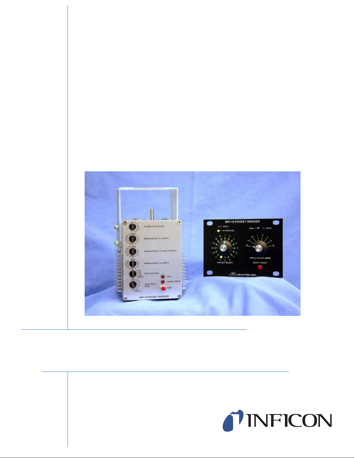
MPI-16 and MPI-16H
Pocket Indexers
IPN 614800 Rev. B
Page 2

Page 3

OPERATION AND SERVICE MANUAL
MPI-16 and MPI-16H
Research Quartz Crystal Microbalance
IPN 614800 Rev. B
®
www.inficon.com reachus@inficon.com
Due to our continuing program of product improvements, specifications are subject to change without notice.
©2007 INFICON
Page 4

Trademarks
The trademarks of the products mentioned in this manual are held by the companies that
produce them.
INFICON® is a trademark of INFICON Inc.
All other brand and product names are trademarks or registered trademarks of their respective companies.
Disclaimer
The information contained in this manual is believed to be accurate and reliable. However, INFICON assumes
no responsibility for its use and shall not be liable for any special, incidental, or consequential damages related
to the use of this product.
Disclosure
The disclosure of this information is to assist owners of INFICON equipment to properly operate and maintain
their equipment, and does not constitute the release of rights thereof. Reproduction of this information and
equipment described herein is prohibited without prior written consent from INFICON, Two Technology Place,
East Syracuse, NY 13057-9714. Phone 315.434.1100. See www.inficon.com.
Copyright
©2003 All rights reserved.
Reproduction or adaptation of any part of this document without permission is unlawful.
First Edition, September 2003. Revision A.
Second Edition, February 2006. Revision A.
Second Edition, October 2007. Revision B.
WARNING
All standard safety procedures associated with the safe
handling of electrical equipment must be observed. Always
disconnect power when working inside the controller. Only
properly trained personnel should attempt to service the
instrument.
Page 5

Warranty
INFICON warrants the product to be free of functional defects in material and
workmanship and that it will perform in accordance with its published specification
for a period of (twenty-four) 24 months.
The foregoing warranty is subject to the condition that the product be properly
operated in accordance with instructions provided by INFICON or has not been
subjected to improper installation or abuse, misuse, negligence, accident,
corrosion, or damage during shipment.
Purchaser's sole and exclusive remedy under the above warranty is limited to, at
INFICON's option, repair or replacement of defective equipment or return to
purchaser of the original purchase price. Transportation charges must be prepaid
and upon examination by INFICON the equipment must be found not to comply
with the above warranty. In the event that INFICON elects to refund the purchase
price, the equipment shall be the property of INFICON.
This warranty is in lieu of all other warranties, expressed or implied and
constitutes fulfillment of all of INFICON's liabilities to the purchaser. INFICON
does not warrant that the product can be used for any particular purpose other
than that covered by the applicable specifications. INFICON assumes no liability in
any event, for consequential damages, for anticipated or lost profits, incidental
damage of loss of time or other losses incurred by the purchaser or third party in
connection with products covered by this warranty or otherwise.
www.inficon.com reachus@inficon.com
Page 6

Page 7

MPI-16 & MPI-16H POCKET INDEXERS
Table of Contents
1 General Description............................................................................1-1
1.1 Purpose.............................................................................................................1-1
1.2 Features............................................................................................................1-1
1.2.1 Indexing ...................................................................................................1-1
1.2.2 Speed........................................................................................................1-1
1.2.3 Torque......................................................................................................1-1
1.2.4 Safety .......................................................................................................1-2
1.2.5 Deposition Controller Interface ...............................................................1-2
1.2.6 Remote Panel...........................................................................................1-2
1.2.7 Error and Fault Detection.........................................................................1-2
1.2.8 Noise Immunity .......................................................................................1-3
1.2.9 Compact Size...........................................................................................1-3
1.3 Specifications – MPI-16 Pocket Indexer .........................................................1-4
1.3.1 Indexing ...................................................................................................1-4
1.3.2 Speed at Output Shaft ..............................................................................1-4
1.3.3 Torque at Output Shaft.............................................................................1-4
1.3.4 Temperature Protection............................................................................1-4
1.3.5 Safety Interlocks ......................................................................................1-4
1.3.6 Inputs/Outputs Interface...........................................................................1-4
1.3.7 Physical....................................................................................................1-5
1.4 Specifications – Remote Panel.........................................................................1-5
1.4.1 Displays....................................................................................................1-5
1.4.2 Controls....................................................................................................1-5
1.4.3 Physical....................................................................................................1-5
1.5 Accessories ......................................................................................................1-6
1.5.1 Remote Panel...........................................................................................1-6
1.5.2 External Interface Cable ..........................................................................1-6
1.5.3 Mounting Bracket ....................................................................................1-6
1.5.4 Power Supply...........................................................................................1-6
2 Package Contents................................................................................2-1
2.1 Ordering Information.......................................................................................2-1
3 Setup and Installation.........................................................................3-1
3.1 Introduction......................................................................................................3-1
3.2 Setup Instructions.............................................................................................3-1
3.3 Configuration Switches - Setup Guide ............................................................3-2
3.3.1 Number of Positions ................................................................................3-3
3.3.2 Banana Pocket #1 Length ........................................................................3-3
3.3.3 Banana Pocket #2 Start Position..............................................................3-4
3.3.4 Banana Pocket #2 Length ........................................................................3-4
3.3.5 Rotation Mode .........................................................................................3-4
3.4 Configuration Examples ..................................................................................3-5
3.4.1 Configuration Error..................................................................................3-6
3.5 Installation in Your System .............................................................................3-8
Page 8

MPI-16 & MPI-16H POCKET INDEXERS
3.6 System Connections.......................................................................................3-11
3.6.1 I/O Port Connector.................................................................................3-11
3.6.2 Interlock Output Connector ...................................................................3-12
3.7 Connecting to the Remote Panel....................................................................3-14
4 Operation.............................................................................................4-1
4.1 Controlling the MPI-16 Manually ...................................................................4-1
4.2 Controlling the MPI-16 Automatically............................................................4-1
4.2.1 Pocket Position Selection.........................................................................4-2
4.2.2 Pocket Position Feedback........................................................................4-3
4.2.3 Remote Selection of Rotation Modes......................................................4-4
4.2.4 Speed Select.............................................................................................4-4
4.2.5 Example: Using the MPI Indexer with the MDC-360.............................4-5
4.3 System Faults...................................................................................................4-8
4.4 Abort and Reset..............................................................................................4-11
5 Troubleshooting Aids..........................................................................5-1
5.1 Returning The Indexer To The Factory...........................................................5-2
6 Appendix A..........................................................................................6-1
Page 9

MPI-16 & MPI-16H POCKET INDEXERS
Table of Figures
FIGURE 3-1 POCKET INDEXER FRONT VIEW......................................................................3-2
FIGURE 3-2 CONFIGURATION EXAMPLE - 4-POSITION CRUCIBLES ....................................3-5
FIGURE 3-3 CONFIGURATION EXAMPLE - 5-POSITION CRUCIBLES ....................................3-5
IGURE 3-4 CONFIGURATION EXAMPLE - 8-POSITION CRUCIBLES ....................................3-6
F
F
IGURE 3-5 MPI-16 OUTLINE DIMENSIONS ......................................................................3-9
FIGURE 3-6 TYPICAL MOUNTING....................................................................................3-10
FIGURE 3-7 SYSTEM CONNECTIONS................................................................................3-13
FIGURE 3-8 REMOTE PANEL – FRONT VIEW....................................................................3-14
IGURE 3-9 REMOTE PANEL - REAR VIEW......................................................................3-15
F
F
IGURE 3-10 POCKET INDEXER REAR VIEW....................................................................3-16
FIGURE 4-1 DSUB-25 FEMALE TO DSUB-37 FEMALE CABLE DIAGRAM.........................4-7
List of Tables
TABLE 3-1 CONFIGURATION ERRORS...............................................................................3-7
TABLE 3-2 I/O PORT SIGNAL ASSIGNMENTS...................................................................3-11
TABLE 4-1 POCKET SELECT INPUTS TRUTH TABLE...........................................................4-3
TABLE 4-2 POCKET POSITION FEEDBACK OUTPUTS TRUTH TABLE ..................................4-4
TABLE 4-3 SPEED SELECT BCD INPUTS TRUTH TABLE ....................................................4-4
TABLE 4-4 SPEED SETTINGS..............................................................................................4-5
TABLE 4-5 SYSTEM FAULTS............................................................................................4-10
TABLE 6-1 QUICK REFERENCE - ERRORS AND FAULTS .....................................................6-1
Page 10

Page 11

MPI-16 & MPI-16H POCKET INDEXERS
1 General Description
1.1 Purpose
The MPI-16 Pocket Indexer allows for automatic or manual control of multi-pocket beam
sources that have a 4:1 gear reduction. It utilizes a stepper motor and is capable of
accurately indexing a very wide assortment of crucibles. Automatic control is easily
achieved by connecting the MPI-16 to a Deposition Controller, such as the INFICON
MDC-360. Manual control is also made simple by connecting the MPI-16 to the optional
Remote Panel. A Safety Interlock relay ensures that the e-beam supply is not active
during pocket rotation.
1.2 Features
The MPI-16 is rich in features and was designed to be the most flexible, powerful, and
intuitive crucible indexer of its kind. There are two versions of the indexers, the MPI-16
(Standard) and MPI-16H (High Torque). Except for the torque and speed, the two
versions have the same functions. The following list summarizes their main
characteristics.
1.2.1 Indexing
Both MPI-16 and MPI-16H can be configured to index up to 16 individual pockets.
Specifically, it can be set for use with 4, 5, 6, 8, 10, 12 or 16 pocket positions, as well as
circular (continuous trough) pockets. Up to two banana (partial trough) pockets of any
length may be specified. UHV (Ultra-High Vacuum) crucibles are also supported. The
MPI-16 can be set to Fast rotation mode, which uses a “smart” algorithm to select the
shortest path to the target pocket (this setting can be overridden, however, by explicitly
specifying clockwise or counter-clockwise rotation).
1.2.2 Speed
1.2.2.1 MPI-16 Speed
While searching for a target pocket, the MPI-16 output shaft rotates at a fixed speed of 16
RPM. While on a Circular or Banana pocket, the output shaft sweeps through the
specified region at a speed that is set by via the remote inputs, the remote panel or on the
indexer. The speed may be set to any one of eight settings, which fall between 0.125
RPM and 16 RPM.
1.2.2.2 MPI-16H Speed
Unlike the standard version, the MPI-16H output shaft rotates at the speed that is set by
the remote inputs, the remote panel or on the indexer, whether it was searching for a
target pocket, or sweeping on a Circular or Banana pocket. The speed may be set to any
one of eight settings, which fall between 0.125 RPM and 16 RPM.
1.2.3 Torque
As mentioned earlier, there are two versions the indexer, the standard torque MPI-16 and
the high torque MPI-16H. In both versions, the indexers normally run in Low Current
mode to save power and reduce heat. They will only switch into higher torque mode, as
General Description 1-1
Page 12

MPI-16 & MPI-16H POCKET INDEXERS
required, to turn the crucible. The maximum torque generated by each version is listed
below.
1.2.3.1 MPI-16 Standard Torque
The Standard indexer, Model MPI-16, is capable of providing up to 187 in-oz. of torque
at output shaft. The output shaft size is ¼ inch in diameter.
1.2.3.2 MPI-16H High Torque
The High Torque Indexer, Model MPI-16H, is capable of providing up to 310 in-oz. of
torque at output shaft. The output shaft size is 5/16 inch in diameter.
1.2.4 Safety
An Abort/Reset button is provided to allow emergency pausing without program
interruption. If this button is held for two seconds, the system resets itself. When
connected to a Deposition Controller, an external Abort signal will also cause a pause in
the program that can be resumed when the Abort signal is removed. The MPI-16
provides an Interlock relay that acts to ensure that the e-beam is never active during
pocket rotation. The MPI-16 will halt operation if it’s maximum torque is exceeded or if
the motor overheats.
1.2.5 Deposition Controller Interface
The MPI-16 supports two modes for interfacing with an external Deposition Controller,
such at the INFICON MDC-360. The simplest method is for the MPI-16 to accept BCD
(Binary Coded Decimal) inputs to select the desired pocket number and provide BCD
outputs to transmit the current pocket number back to the Controller. An alternate
method accepts two separate inputs (Clockwise and Counter-Clockwise), which rotate the
MPI-16 by one pocket in the indicated direction whenever either signal is asserted.
1.2.6 Remote Panel
The Remote Panel is a rack-mount control unit that provides pocket selection, speed
selection, an easy-to-read LED display of the current pocket position and an Abort/Reset
button. The Remote Panel is required if you do not plan to use the MPI-16 with an
external controller, since it will be the only way to select pockets. Even when using
external control, the Remote Panel may be useful since it allows easy manual pocket
selection. For example, the remote panel allows the operator to check the material levels
in the individual pockets in between deposition runs.
1.2.7 Error and Fault Detection
In the event of any type of error or fault, the MPI-16 makes it very clear what problem
has occurred. If the unit has not been configured correctly, a blinking LED will flash a
code that indicates what configuration changes need to be made. Similarly, if there is a
run-time fault, a different blinking LED will flash a code that indicates what error
occurred. Table 3-1 and Table 4-5 System Faults in this manual defines the meaning of
the blink-codes, and a Quick Reference is provided in Appendix A.
1-2 General Description
Page 13

MPI-16 & MPI-16H POCKET INDEXERS
1.2.8 Noise Immunity
The MPI-16 employs numerous electronics techniques (including the use of optoisolators, switch debouncing and smoothing filters) to ensure that it operates correctly
even in electrically noisy environments.
1.2.9 Compact Size
The MPI-16 has a very small footprint measuring only 4.0” x 4.2” so it requires minimal
mounting space.
General Description 1-3
Page 14

MPI-16 & MPI-16H POCKET INDEXERS
1.3 Specifications – MPI-16 Pocket Indexer
1.3.1 Indexing
Number of Positions Supported Circular, 4, 5, 6, 8, 10, 12, 16
“Banana” Pockets Supported Up to 2
Rotation Modes Fast, UHV, CW, CCW, Remote
Position Accuracy and
Repeatability
1.3.2 Speed at Output Shaft
Pocket Search Speed (MPI-16) 16 RPM
Pocket Search Speed (MPI-16H) 16, 8, 4, 2, 1, 1/2, 1/4, 1/8 RPM
Circular, Banana Sweep Speed 16, 8, 4, 2, 1, 1/2, 1/4, 1/8 RPM
1.3.3 Torque at Output Shaft
Max. Torque (MPI-16) 187 in-oz.
Max. Torque (MPI-16H) 310 in-oz.
1.3.4 Temperature Protection
Auto Shut-off Temperature
Resume From Shut-off
1.3.5 Safety Interlocks
Relay output, SPST 120 VA, 2A max.
Disable Ground true.
1.3.6 Inputs/Outputs Interface
Inputs Ground true.
Input Functions Pocket Selection: 4-bit BCD
Outputs Optically isolated transistors. Ground true.
Output Functions Pocket Position: 4-bit BCD
1° at output shaft
100 ± 1°C (212 ± 1.8°F)
85 ± 6°C (185 ± 10.8°F)
4.7 K ohms pull up to 5 VDC internally.
4.7 k ohms pull up to 5 VDC internally.
Speed Selection: 3-bit BCD
Clockwise rotation selection
Counter Clockwise rotation selection
Reset
4.7 K ohms pull-up resistors. 50 mA max.
In Pocket Position
Pocket Fault
1-4 General Description
Page 15

MPI-16 & MPI-16H POCKET INDEXERS
1.3.7 Physical
Dimensions [w] × [h] × [d]
(including shaft length and
protruded switches and
connectors)
Weight
Power Supply 48 VDC, 1.1 A, Desktop type
Input Power Requirements 100-250 VAC, 1.5 A at 47-63 Hz.
Mounting Bracket (included) Mounts to a 1” rotary motion feed through,
4.00” × 5.29” × 4.19”
(10.2 cm × 13.44 cm × 10.64 cm)
4.2 lbs. (1.9 kg)
accommodates base plate thickness of 1/2” to 1-1/8”.
1/4” diameter for the MPI-16 Output Shaft Size
5/16”diameter for the MPI-16H
1.4 Specifications – Remote Panel
1.4.1 Displays
16 Green LEDs Indicating current pocket position
Red Fault LED Indicating a fault
Green In Position LED Indicating a selected position is reached.
1.4.2 Controls
Auto-Manual Toggle Switch Selecting the operating mode.
Pocket Select Rotary Switch Selecting the desired pocket position (Manual Mode)
Speed Select Rotary Switch Selecting the desired sweep for “banana” pocket
(Manual Mode)
Abort/Reset Button Use to stop the indexer operation or to reset the
indexer.
1.4.3 Physical
Dimensions [w] × [h] × [d]
(Including protruded switches
and connectors)
Pocket Select Rotary Switch Selecting the desired pocket position (Manual Mode)
Speed Select Rotary Switch Selecting the desired sweep for “banana” pocket
Abort/Reset Button Use to stop the indexer operation or to reset the
4.72” × 3.47” × 2.00” (11.99 cm × 8.81 cm × 5.08
cm)
(Mounts in a 3.5” quarter panel)
(Manual Mode)
indexer.
General Description 1-5
Page 16

MPI-16 & MPI-16H POCKET INDEXERS
1.5 Accessories
1.5.1 Remote Panel
The Remote Panel is a required system component if you have chosen to operate the
MPI-16 without external control. The Remote Panel is a 3.5” high, quarter-size rackmountable interface that provides a Pocket Select Switch, Speed Select Switch, and an
Abort/Reset button. You may also toggle between Automatic and Manual operation if
you are using the Remote Panel in conjunction with external control. If your Pocket
Indexer kit included the Remote Panel, a 25-pin (straight-through) cable is also provided
for connectivity.
1.5.2 External Interface Cable
A standard 25-pin cable is supplied with all MPI-16 units to allow you to interface the
Pocket Indexer with any control device you wish. The most common options will be to
control the MPI-16 from a Deposition Controller or from a Programmable Logic
Controller (PLC) in your system. To provide maximum flexibility, the wires at the
opposite end of the cable have been left unconnected (loose). Refer to Table 3-2 for the
signal definitions of each pin. Since the colors of each wire may vary, a separate page
will be included with your interface cable specifying the color code.
If you do not plan on using the optional Remote Panel, you may connect the External
Interface Cable directly to the MPI-16. If you will be using the Remote Panel (via the
provided connector), you must connect the External Interface Cable to the auxiliary
connector on the Remote Panel itself. It will act the same exact way as if your control
device were plugged directly into the MPI-16.
1.5.3 Mounting Bracket
The MPI-16 includes a mounting bracket to allow for easy installation in your system.
The bracket mounts to a 1” rotary feed-through, and can accommodate a base plate
thickness of 1/2” to 1-1/8”. Please see Section 3.5 (Installation in Your System) for
further details.
1.5.4 Power Supply
A 48-volt (1.1 amp) power supply is included to provide reliable power for your MPI-16.
This powers the stepper motor as well as all of the low-voltage logic circuitry inside the
Pocket Indexer. It is recommended that you only use the provided power supply to
ensure reliability and integrity of the indexer operation.
1-6 General Description
Page 17

MPI-16 & MPI-16H POCKET INDEXERS
2 Package Contents
Carefully inspect your MPI-16 Indexer and its shipping container for evidence of possible
shipping damage or loss. If such evidence is present, a report should be filed with the
carrier as soon as possible. Keep the shipping container as evidence if shipping damage
is present or for possible future return of the unit. Check the material received against the
packing list to be certain that all material is accounted for. The following items should
have been included with your Indexer:
1 MPI-16 Pocket Indexer and mounting bracket
1 Operation Manual
1 Power Supply
1 Power cord
1 I/O cable (DSUB-25 Female to open-ends, 5 feet long)
1 Interlock Connector, (2-Pin terminal block)
Optionally, your package may also include the following items:
1 Remote Panel
1 DSUB-25 Female to DSUB-25 Male Cable
If you have purchased a INFICON MDC-360 Film Deposition Controller with your MPI-16
Pocket Indexer, the following cable may have also been included, as an option.
1 DSUB-25 Female to DSUB-37 Female
This cable has a set of pre-defined I/Os to ease your wiring for I/O connections between
the two units. All you have to do is to configure your indexer for your crucible, and
program the MDC-360 to drive the indexer. See Section 4.2.5.
2.1 Ordering Information
Part Number Description
614800 MPI-16 Operation Manual
614410 1” Hole Mounting Bracket
614209 I/O Cable, DSUB-25 Female to open-ends, 5 feet
long
800401 Mounting Screw, #8-32 x ¼” long
803337 Washer, Int/Ext Tooth, #8
803081 Power Cord
885077 Interlock Connector
900038 Power Supply
828011 Cable, DSUB-25 Female to DSUB-25 Male
614208 Cable, DSUB-25 Female to DSUB-37 Female
Refer to INFICON’s Price List for more accessories and other products.
Package Contents 2-1
Page 18

Page 19

MPI-16 & MPI-16H POCKET INDEXERS
3 Setup and Installation
3.1 Introduction
The MPI-16 Pocket Indexer is capable of working with a very large assortment of
crucibles. You may interface the MPI-16 with crucibles having 4, 5, 6, 8, 10, 12, or 16
pocket positions, as well as banana (partial trough) or circular (continuous trough)
crucibles. Banana length is defined as the number of pocket positions. For banana or
continuous trough pockets, you may specify the speed at which the MPI-16 sweeps
through the region.
You must configure the MPI-16 to meet your specific system’s requirements.
Configuration is achieved by setting the Configuration Switches located on the front of
the MPI-16’s housing. Before installing the MPI-16 into your system, you should use
this guide to set the Configuration Switches and ensure that the combination that you
enter does not result in a Configuration Error.
3.2 Setup Instructions
• Place the MPI-16 in a position that allows easy access to the Configuration
Switches.
• Use the Setup Guide (Section 3.3) in this chapter to determine the correct setting
for each of the Configuration Switches. Dial in the settings that match your
crucible.
• Apply power to the unit, or press the Abort/Reset button if the power is already
applied.
• If you have entered an invalid combination of switches, the Config. Error LED
will blink. The number of times (in a row) that it blinks will help you determine
the type of error you have encountered.
• Reevaluate your Configuration Switch settings, and make any alterations to the
switches that you believe will solve the problem. When finished, press the
Abort/Reset button.
• Once a valid combination of switches is entered, the MPI-16 will begin operating
immediately (its first action will be to locate the first pocket).
• Keep in mind that a successful combination does not ensure that you have entered
the correct settings for your system, but simply a combination that the MPI-16
supports. After installation, you should test the MPI-16 with your specific
crucible before actually performing a real operation.
Setup and Installation 3-1
Page 20

MPI-16 & MPI-16H POCKET INDEXERS
Because it can be changed during normal operation, Speed Select is not considered a
normal Configuration Switch. Its setting has no effect on the success or failure of a
Configuration Setup. Its operation is covered in Section 3.3.
Figure 3-1 Pocket Indexer Front View
3.3 Configuration Switches - Setup Guide
The Configuration Switches on the MPI-16 are defined as follows –
3-2 Setup and Installation
Page 21

MPI-16 & MPI-16H POCKET INDEXERS
3.3.1 Number of Positions
This setting indicates how many positions the MPI-16 can index. The spacing between
the positions is automatically determined so that all positions are the exact distance apart
from each other. If your crucible contains any Banana Pockets, you should count each
position that the Banana Pockets sweep over as separate positions.
The MPI-16 is capable of indexing crucibles with 4, 5, 6, 8, 10, 12, or 16 positions.
Circular (continuous trough) pockets may also be specified.
Setting Meaning
CIR.
4
5
6
8
10
12
16
Number of Positions = 1 (Circular) Number of Positions = 4 Number of Positions = 5 Number of Positions = 6 Number of Positions = 8 Number of Positions = 10 Number of Positions = 12 Number of Positions = 16
3.3.2 Banana Pocket #1 Length
This setting indicates the length of the first Banana Pocket. The first Banana Pocket
must always start at the first position (Home). You may choose for the first Banana
Pocket to occupy any number of pocket positions, with the following restrictions:
• A Banana Pocket must occupy at least two positions, so a length of “1” is invalid.
• The length must be less than or equal to Number of Positions.
Setting Meaning
NONE
1
n (2 - 15)
No Banana Pockets are specified
Not Allowed
Banana Pocket #1 occupies the first ‘n’ pocket positions
Setup and Installation 3-3
Page 22

MPI-16 & MPI-16H POCKET INDEXERS
3.3.3 Banana Pocket #2 Start Position
This setting indicates the position number that the second Banana Pocket starts on. You
may choose for the second Banana Pocket to start on any pocket position, with the
following restrictions:
• Specifying a second Banana Pocket implies that you have already specified a first
Banana Pocket (with a length of at least two positions), so the first possible
position to start a second Banana Pocket is “3.”
• Starting a Banana Pocket in position 16 would not accommodate the minimum
size of two positions, so “16” is an invalid setting.
• The Start Position should be set so that it doesn’t overlap with the length of the
first Banana Pocket.
Setting Meaning
NONE
1, 2
n (3 - 15)
A Second Banana Pocket is not specified
Not allowed
Banana Pocket #2 starts at Position ‘n’
3.3.4 Banana Pocket #2 Length
This setting indicates the length of the second Banana Pocket. You may choose for the
second Banana Pocket to occupy any number of pocket positions, with the following
restrictions:
• A Banana Pocket must occupy at least two positions, so a length of “1” is invalid.
• Since a second Banana Pocket may start at a minimum position of “3,” and there
are a maximum of 16 positions, the length must be less than “15.”
Setting Meaning
NONE
1
n (2 - 14)
15
No Second Banana Pocket is specified
Not allowed
Banana Pocket #2 occupies ‘n’ positions
Not allowed
3.3.5 Rotation Mode
This setting indicates the mode of operation of the MPI-16. The following modes are
supported:
• Fast – This mode uses a “smart” algorithm to detect the shortest path (clockwise
or counter-clockwise) to the selected pocket.
• UHV (Ultra High Vacuum) – Certain crucible systems, due to obstruction, are not
permitted to pass through the “Home” location. This mode finds the selected
pocket using the path that is not blocked.
• CW (Clockwise) – This mode always forces clockwise operation.
• CCW (Clockwise) – This mode always forces counter-clockwise operation.
• Remote – This mode disables the manual Pocket Select feature and, instead,
allows for control through an external deposition controller. It uses two input
signals (CW & CCW) to determine the direction of rotation and four feedback
output signals to convey the current pocket number back to the controller.
3-4 Setup and Installation
Page 23

MPI-16 & MPI-16H POCKET INDEXERS
3.4 Configuration Examples
These examples illustrate a few examples of crucible setups and corresponding
Configuration Switch settings. Since Rotation Mode does not affect the pocket
positions, only the first four Configuration Switches are taken into account.
Format
Number of Positions,
Banana Pocket #1 Length,
Banana Pocket #2 Start Position,
Banana Pocket #2 Length
:
CIR, 0, 0, 0
Figure 3-2 Configuration Example - 4-Position Crucibles
4, 0, 0, 0
4, 2, 0, 0
4, 3, 0, 0
5, 0, 0, 0 5, 3, 0, 0
Figure 3-3 Configuration Example - 5-Position Crucibles
5, 4, 0, 0
Setup and Installation 3-5
Page 24

MPI-16 & MPI-16H POCKET INDEXERS
8, 0, 0, 0
Figure 3-4 Configuration Example - 8-Position Crucibles
3.4.1 Configuration Error
When the MPI-16 is reset, it scans the five Configuration Switches and internally creates
Pocket Position Tables for use during operation. There are a multitude of Configuration
Switch settings that do not correspond with crucibles that are supported by the MPI-16,
and you will receive a Configuration Error if you try to specify one of these modes. To
help you determine why your switch selection is invalid, the Config. Error LED will
blink a code telling you what type of Configuration Error occurred.
Table 3-1 describes the possible conflicts that cause the Config. Error LED to blink.
8, 6, 0, 0
8, 3, 5, 4
3-6 Setup and Installation
Page 25

MPI-16 & MPI-16H POCKET INDEXERS
1 Blink – Switch Out Of Range Error
Conflict:
• The Number of Positions switch must
• The Rotation Mode switch must
2 Blinks – Circular Pocket Error
Condition:
• Circular Mode is set (Number of Positions = “Cir.”).
Conflicts:
• The Rotation Mode switch must
• Banana Pocket #1 Length must
• Banana Pocket #2 Start Position must
• Banana Pocket #2 Length must
* Note: Setting Banana Pocket #1 Length equal to Number of Pockets also specifies a
Circular Pocket, but it is recommended that you use Number of Pockets = “Cir.”
3 Blinks – No Banana Pockets Error
Condition:
• No Banana Pockets (Banana Pocket #1 Length = 0)
Conflicts:
• Banana Pocket #2 Start Position must
• Banana Pocket #2 Length must
be set on a valid, marked setting.
be set on a valid, marked setting.
be set to either CW or CCW.
be set to 0
be set to 0, and
be set to 0.
be set to 0, and
be set to 0.
4 Blinks – One Banana Pocket Error
Conflicts:
• Banana Pocket #1 Length cannot
• Banana Pocket #1 Length must
5 Blinks – No Second Banana Pocket Error
Condition:
• No Second Banana Pocket (Banana Pocket #2 Start Position = 0)
Conflict:
• Banana Pocket #2 Length must
6 Blinks – Two Banana Pockets Error
Condition:
• Banana Pocket #2 Start Position > 0
Conflicts:
• Banana Pocket #2 Length cannot
• Banana Pocket #2 Length cannot
is not considered a Banana Pocket.
• Banana Pocket #2 Start Position must
#1 Length + 1).
• Banana Pocket #2 Start Position + Banana Pocket #2 Length must
equal to (Number of Positions + 1).
• Banana Pocket #1 Length + Banana Pocket #2 Length must
to Number of Positions.
be set to 1.
be less than Number of Positions.
be set to 0.
be set to 0.
be set to 1. A pocket occupying a single position
be greater than or equal to (Banana Pocket
be less than or
be less than or equal
Table 3-1 Configuration Errors
Setup and Installation 3-7
Page 26

MPI-16 & MPI-16H POCKET INDEXERS
3.5 Installation in Your System
After successfully configuring the MPI-16, it is ready for installation on your system.
WARNING
Lethal power resulting in electrical shocks may be present in your system. Make
sure your system power is removed and discharged before installing the MPI-16.
The MPI-16 assembly comes with a mounting bracket. This bracket mounts to a 1”
rotary feed-through, and can accommodate a base plate thickness of 1/2” to 1-1/8”. The
only extra component needed is a coupling to join the drive shaft to the rotary feedthrough. See Figure 3-6. We recommend a flexible coupling such as a HeliCal P/N
HCR-075-8 to minimize torque lost in misalignment of the shafts, if any.
Refer to Figure 3-5 for the MPI-16 dimensions. Note the drive shaft offset with regard to
the unit’s center. Observe the location of the DB25 I/O Port connector. Allow clearance
for it.
1. Manually rotate your crucible to position 1 (Home).
2. Loosen the four socket screws on each side of the bracket. You may have to
remove the two lower screws completely if your base plate is less then 1” thick.
Note: Use only the screws and washers (#8-32 x 1/4” long) supplied with
your MPI-16. Using screws longer than 1/4” long will damage the internal
circuitry.
3. Slide the flexible coupling over the drive shaft. Do not tighten.
4. Line up the 1” hole in the bracket with the 1” rotary feed-through. Secure the
bracket to the base plate using the washer and nut supplied with your rotary feedthrough.
5. Apply power to the MPI-16. It will start to rotate to find its ‘home’ position.
6. Once the MPI-16 has stopped at home, push the MPI-16 chassis up on the bracket
so that the drive shaft and feed-through shaft almost touch. Secure the MPI-16
housing to the bracket by tightening the socket screws on each side of the bracket.
7. Slide the flexible coupling up and over both shaft. Set the coupling so that it
covers an equal distance on both shafts. Make sure the crucible has not moved
and tighten the coupling.
3-8 Setup and Installation
Page 27

MPI-16 & MPI-16H POCKET INDEXERS
Figure 3-5 MPI-16 Outline Dimensions
Setup and Installation 3-9
Page 28

MPI-16 & MPI-16H POCKET INDEXERS
1” ROTARY MOTION FEEDTHROUGH
SUPPLIED)
(NOT
MOUNTING BRACKET
VACUUM BASE PLATE
COUPLING
(NOT
SUPPLIED)
WASHER
SUPPLIED)
(NOT
(NOT
SUPPLIED)
SCREWS &
WASHE
R MOUNTING
(FO
BRACKET)
NUT
RS (8X)
MPI-16 INDEXER
Figure 3-6 Typical Mounting
3-10 Setup and Installation
Page 29

MPI-16 & MPI-16H POCKET INDEXERS
3.6 System Connections
On the rear side of the MPI-16, there are two connectors providing all the necessary
signals to complete interfacing with other system components (see Figure 3-10). The
DSUB-25 Male, I/O Port connector provides inputs and outputs, and the 2-Pin terminal
block, Interlock Output connector, provides the safety interlock signal.
3.6.1 I/O Port Connector
Use the provided DSUB-25 Female I/O cable to connect the MPI-16 to your film
deposition controller or PLC (programmable logic controller). Connect the female end of
the cable to the MPI-16 I/O Port, and wire the open-end of the cable to your controller
accordingly. Table 3-2 shows the signal pin assignments for the MPI-16 I/O Port
connector. Refer to your controller manual for their I/Os.
Signal Name Signal Type True Condition Pin No.
Speed Select– Bit 0 Input Signal Ground True 15
Speed Select– Bit 1 Input Signal Ground True 14
Speed Select– Bit 2 Input Signal Ground True 2
Clockwise Rotation Input Signal Ground True 17
Counter Clockwise Rotation Input Signal Ground True 5
Pocket Select– Bit 0 Input Signal Ground True 6
Pocket Select– Bit 1 Input Signal Ground True 7
Pocket Select– Bit 2 Input Signal Ground True 20
Pocket Select– Bit 3 Input Signal Ground True 18
Pocket Position – Bit 0 Output
Pocket Position – Bit 1 Output
Pocket Position – Bit 2 Output
Pocket Position – Bit 3 Output
Low true∗
Low true∗
Low true∗
Low true∗
In Position Output
Fault Output
Low true∗
Low true∗
Disable Input Signal Ground True 19
Reset Input Signal Ground True 12
Inputs Return Signal Ground 1, 13
Outputs Return Optocoupler 10
Not Assigned Unused 3, 4, 16, 23
Table 3-2 I/O Port Signal Assignments
22
9
21
8
11
24
∗
Outputs are pulled-up to 5 volts through a 4.7 K ohms resistors (50 mA max). Low true is with respect to
the output return (Pin 10). All outputs are optically isolated transistors.
Setup and Installation 3-11
Page 30

MPI-16 & MPI-16H POCKET INDEXERS
If you have purchased a INFICON’s MDC-360 Thin Film Controller with your MPI-16
Pocket Indexer, a DSUB-25 Female to DSUB-37 Female cable may have also been
included, as an option. This cable has a set of pre-defined I/Os to ease your wiring for
I/O connections between the MPI-16 and the MDC-360. Connect the DSUB-25 Female
end to the MPI-16 I/O connector and the DSUB-37 Female end to the MDC-360 I/O
connector. All you have to do is to configure your indexer for your crucible, and
program the MDC-360 to drive the indexer.
3.6.2 Interlock Output Connector
Use the 2-Pin terminal block connector (provided) and discrete wires (not provided) to
connect the Interlock Output on the MPI-16 to your e-beam interlock input to prevent the
beam from being on while the crucible is in motion. The MPI-16 Interlock Output is a
relay contact. It closes when it is safe to turn on the e-beam and open up when it is NOT
safe to turn on the beam. Refer to your e-beam gun manual for its safety interlock
requirements.
3-12 Setup and Installation
Page 31

MPI-16 & MPI-16H POCKET INDEXERS
Figure 3-7 System Connections
Setup and Installation 3-13
Page 32

MPI-16 & MPI-16H POCKET INDEXERS
3.7 Connecting to the Remote Panel
If you plan on controlling the MPI-16 manually, you must use the Remote Panel to do so.
gin by installing the Remote Panel in your instrument rack. It can be placed side-by-
Be
side with other half-size or quarter-size rack-space equipment. Since it derives power
m its connection to the Pocket Indexer, no additional power supply is required.
fro
With the Pocket Indexer unplugged, attach the male end of the provided DB-25 cable to
the MPI-16, and attach the female end of the cable to the Remote Panel.
you are using the Remote Panel as well as a Deposition Controller, you must use the
If
same cable as you would normally use to connect the MPI-16 to your controller. The 25pin male jack on the Remote Panel is a pin-for-pin duplication of the I/O of the MPI-16
itself, but now runs through the Remote Panel’s Auto/Man. switch.
Figure 3-8 Remote Panel – Front View
3-14 Setup and Installation
Page 33

MPI-16 & MPI-16H POCKET INDEXERS
Figure 3-9 Remote Panel - Rear View
Setup and Installation 3-15
Page 34

MPI-16 & MPI-16H POCKET INDEXERS
Figure 3-10 Pocket Indexer Rear View
3-16 Setup and Installation
Page 35

MPI-16 & MPI-16H POCKET INDEXERS
4 Operation
Regardless of whether you will be running the MPI-16 in Manual or Automatic mode, be
sure that you have read Section 3 and have set up your Pocket Indexer correctly. The
Configuration Switch settings dictate how the MPI-16 operates.
Setting up for automatic operation is more involved than manual operation, but it can
ultimately lead to greater automation and significant timesaving.
4.1 Controlling the MPI-16 Manually
Controlling the MPI-16 manually requires the Remote Panel. On your Remote Panel, flip
the switch labeled Auto / Man. to the Man. setting. This activates the Pocket Select and
Speed Select knobs on the Remote Panel instead of allowing input from an external
source, such as a Deposition Controller. Also, on the MPI-16 itself, make sure that the
Speed Select switch is set to Remote, indicating that the speed setting is to come from
the Remote Panel.
Regardless of whether you will be running the MPI-16 in Manual or Automatic mode, be
sure that you have read Section 3 and have set up your Pocket Indexer correctly. The
Configuration Switch settings dictate how the MPI-16 operates.
Manual operation is very straightforward. Upon reset (unless Circular Mode was set), the
MPI-16 finds Home (locates the first pocket). After Home is found, you are free to move
the Pocket Select and Speed Select knobs to any position you desire. The Rotation
Mode Configuration Switch determines the method that is used to get to the selected
pocket (see Section 3.3).
Note that in the standard version MPI-16, the Speed Select setting only applies to Banana
Pocket and Circular Mode, and not the seek home speed (fixed at 16 RPM). However, in
the high torque version MPI-16H, the Speed Select setting applies to all modes: seek
home, Banana Pocket and Circular Modes.
If you select a pocket out of the range set by the Number of Pocket switch, the Pocket
Indexer will continue to go to the last valid pocket that it sensed, but it will not consider
itself “In Position,” nor will the Interlock relay be turned on.
The Abort/Reset button on the Remote Panel serves two purposes. Pressing it once will
cause the indexer to pause and the Interlock to turn off. Pressing it again causes the
process to continue from where it left off. At any point, though, if you hold the
Abort/Reset button for two seconds, the system will reset itself as if the power were
turned on.
4.2 Controlling the MPI-16 Automatically
Controlling the MPI-16 automatically requires an external Deposition Controller or PLC.
Combining external control with the MPI-16 Pocket Indexer provides a fully automated
solution for your deposition process. Although not required when controlling the MPI-16
automatically, the Remote Panel is still a very useful add-on. Having a Remote Panel in
Operation
4-1
Page 36

MPI-16 & MPI-16H POCKET INDEXERS
addition to a Deposition Controller allows the operator to run a program, pause the
program, check the material level of a particular pocket using the manual Pocket Select
knob on the Remote Panel, and resume the program with the Deposition Controller.
If you are using a Remote Panel in conjunction with a Deposition Controller, flip the
switch labeled Auto / Man. to the Auto setting. This allows the Pocket Select and
Speed Select signals from your Deposition Controller or PLC to be sent to the indexer.
When you want to use the Remote Panel, simply switch the Auto / Man. Switch to the
Man. setting.
Although most Deposition Controllers are capable of automatically selecting the speed as
well as the pocket, it is often not necessary to have such control over the speed setting. If
you know that the sweeping speed for Circular and Banana Pockets will not need to be
changed, you can set the Speed Select switch on the indexer itself. If you want to select
various speeds remotely, set the Speed Select switch on the MPI-16 to Remote. Now,
the speed selection will either come from the Deposition Controller (Auto / Man. =
Auto) or the Remote Panel (Auto / Man. = Man.)
4.2.1 Pocket Position Selection
There are two methods of controlling the pocket selection with an external controller, a 4bit BCD (Binary Coded Decimal) signal or a directional signal. Each of these methods is
described below.
4.2.1.1 BCD Code Drive
This method involves setting the Pocket Select Inputs to the desired pocket as a 4-bit
BCD signal. See Table 4-1 below for selection truth table. Note that, since it is BCD, if
your crucible has fewer than 16 pockets, you don’t have to use all four-bit inputs. For
example, if you have a 4-pocket crucible, you only need to use Bit 0 and Bit 1.
In this selection mode, as soon as a new value is detected (assuming it is in range), the
MPI-16 immediately begins to move to that pocket. This will be the mode of operation if
the Rotation Mode switch is set to Fast, UHV, CW, or CCW.
Pocket Select Inputs
Bit 3 Bit 2 Bit 1 Bit 0 Pocket Position
0 0 0 0 1
0 0 0 1 2
0 0 1 0 3
0 0 1 1 4
0 1 0 0 5
0 1 0 1 6
0 1 1 0 7
0 1 1 1 8
1 0 0 0 9
1 0 0 1 10
1 0 1 0 11
4-2 Operation
Page 37

MPI-16 & MPI-16H POCKET INDEXERS
1 0 1 1 12
1 1 0 0 13
1 1 0 1 14
1 1 1 0 15
1 1 1 1 16
Table 4-1 Pocket Select Inputs Truth Table
If you select a pocket out of the range set by the Number of Pocket switch, the Pocket
Indexer will continue to go to the last valid pocket that it sensed, but it will not consider
itself “In Position,” nor will the Interlock relay be turned on.
4.2.1.2 Directional Drive
The alternate method involves sending “Directional Drive” signals from the Deposition
Controller. In this mode, when “CW” input is asserted, the MPI-16 rotates clockwise
exactly one pocket, and when “CCW” input is asserted, the MPI-16 rotates counterclockwise exactly one pocket. The MPI-16 will pause briefly to allow the external
controller to sense the current position before another CW or CCW signal may be
accepted. This will be the mode of operation if the Rotation Mode switch is set to
Remote.
4.2.2 Pocket Position Feedback
Typically, the Deposition Controller’s program will want to know what pocket the Pocket
Indexer is currently on. To facilitate this, a 4-bit “Pocket Feedback” signal is sent back to
the controller. This signal is changed whenever the MPI-16 advances to a new pocket
position, even if it is not necessarily the target pocket. See Table 4-2 below for position
feedback truth table.
Pocket Position Feedback Outputs
Bit 3 Bit 2 Bit 1 Bit 0 Pocket Position
0 0 0 0 1
0 0 0 1 2
0 0 1 0 3
0 0 1 1 4
0 1 0 0 5
0 1 0 1 6
0 1 1 0 7
0 1 1 1 8
1 0 0 0 9
1 0 0 1 10
1 0 1 0 11
1 0 1 1 12
1 1 0 0 13
1 1 0 1 14
1 1 1 0 15
1 1 1 1 16
Operation
4-3
Page 38

MPI-16 & MPI-16H POCKET INDEXERS
Table 4-2 Pocket Position Feedback Outputs Truth Table
4.2.3 Remote Selection of Rotation Modes
The Rotation Mode Configuration Switch determines the type of command it waits for.
Upon reset (unless Circular Mode was set), the MPI-16 finds Home (locates the first
pocket). After Home is found, the Pocket Indexer awaits a pocket selection command
from the Deposition Controller.
As mentioned ealier, if Rotation Mode is set to Fast, UHV, CW, or CCW, the MPI-16
awaits a 4-bit BCD signal to select the next pocket. If Rotation Mode is set to Remote,
the MPI-16 awaits a CW or CCW “Directional Drive” signal.
4.2.4 Speed Select
NOTE: MPI-16 Speed Select only controls the rotating speed in Circular and Banana
Pocket Modes. MPI-16H Speed Select controls the rotating speed of all modes:
Seeking home, Circular and Banana Pocket Modes.
The available Speed Select settings are shown in Table 4-3 below along with input
selections.
Speed Select Inputs
Bit 2 Bit 1 Bit 0
1 1 1 16
1 1 0 8
1 0 1 4
1 0 0 2
0 1 1 1
0 1 0 1/2
0 0 1 1/4
0 0 0 1/8
Table 4-3 Speed Select BCD Inputs Truth Table
You may set or control the Speed Select setting a number of different ways:
• If your indexer is an MPI-16 and your crucible does not contain any Circular or
Banana Pockets, you don’t need to worry about the setting at all. However, if it is
an MPI-16H, you need to select a speed that fits for your application as this speed
also dictates the home seek speed.
• If you are certain that you will not need to change the Speed Select setting
frequently, you should set the Speed Select switch located on the MPI-16 itself.
Speed at Motor Shaft (RPM)
• If you will need to manually change the sweeping speed frequently, you will need
to connect the MPI-16 to the Remote Panel. You must first set the Speed Select
4-4 Operation
Page 39

MPI-16 & MPI-16H POCKET INDEXERS
switch located on the MPI-16 to Remote, indicating you will be controlling the
speed remotely. Then, as long as the Auto/Man. switch on the Remote Panel is
set to Man., you will be able to control the sweeping speed during run-time with
the Remote Panel’s Speed Select switch.
• If you need to change the Speed Select setting as part of your Deposition
Controller’s program, make sure that the correct connections have been made
between your controller and the MPI-16 (see Figure 3-7). You must set the
Speed Select switch located on the MPI-16 to Remote, indicating you will be
controlling the speed remotely. Then, as long as the Auto/Man. switch on the
Remote Panel is set to Auto, you will be able to control the sweeping speed
during run-time through your Deposition Controller’s I/Os. Refer to Table 4-3 for
speed selection via the indexer’s inputs.
4.2.4.1 Drive Shaft Speed vs. Crucible Speed
The speed at the shaft is four times as fast as the speed of the crucible, since a 4:1 speed
reduction gear is typically included in industry standard crucibles. Table 4-4 lists the
drive shaft speed vs. the speed at the crucible.
Speed at Motor Shaft (RPM) Speed at Crucible (RPM)
16 4
8 2
4 1
2 1/2
1 1/4
1/2 1/8
1/4 1/16
1/8 1/32
Table 4-4 Speed Settings
4.2.5 Example: Using the MPI Indexer with the MDC-360
This example shows how to interface the MDC-360/361/370 with the MPI-16 in BCD
Control mode. Interfacing the MPI-16 to a non-INFICON controller may differ slightly
depending the controller used. Consult the manual of your Deposition Controller for
more information on interfacing it with the MPI-16 in either BCD Control or Direct
Control mode.
1. Make sure that you have properly connected the MDC-360 as shown in Figure
3-7.
2. Begin by turning on the MDC-360 and exiting Abort mode.
3. Under the Main Menu, select “Edit System Setup”
4. Select “Edit Source Setup”
5. Select a Source Setup number to be associated with your specific crucible.
6. Set the number of pockets parameter to match your crucible.
7. Set the Control Parameter to BCD.
Operation
4-5
Page 40

MPI-16 & MPI-16H POCKET INDEXERS
8. Set the Drive parameter to either “Up,” “Down,” or “Fast.” (Fast mode will turn
the crucible in both directions)
9. Set the Feedback Type parameter to BCD.
10. Set the Indexer Delay parameter to 30 seconds.
11. Return to the Main Menu, and select “View/Edit Material”
12. Select a material that you would like to assign to a particular Pocket Number.
13. Modify the “Pocket” setting and, if desired, any other settings particular to your
material.
14. Return to the Main Menu, and select “View/Edit Process.”
15. Create or copy a process to edit.
16. Edit the layers to indicate the order of the pockets you would like your program to
cycle through.
17. When finished editing, press the “Start” button to select and run the program you
have just created.
The MDC will have created a number of “SourceN PocketX” inputs and outputs based
on the number of pockets setting, where N is the source number and X is the pocket
number. The outputs must be connected to the “Pocket Select Bit X” inputs of the MPI-
16. The inputs must be connected to the “Pocket Position Bit X” outputs of the MPI-16.
You may also want to connect the Abort output of the MDC to the Disable input of the
MPI-16 to disable rotation when the controller is aborted.
If you purchased the special cable to connect the MPI-16 to the MDC (PN#614208), then
all of these connections are already made, see Figure 4-1. Note that this cable is wired
for up to 16-Pocket crucible (4 outputs and 4 inputs) AND that it utilizes the first four
inputs and outputs of the MDC I/O, for selecting the pocket and position feedback. All
other I/Os are not connected. See Figure 4-1.
Simply plug the 37-pin DSUB connector into one of the MDC’s passive I/O cards. Plug
the other end of the cable into either the “Controller” connector on the Remote Panel or
the “I/O Port” of the MPI-16.
Any problems that you encounter in this setup are most likely due to wiring problems.
Return to Section 3.6 to make sure that all of the proper connections were made between
your devices.
4-6 Operation
Page 41

MPI-16 & MPI-16H POCKET INDEXERS
Figure 4-1 DSUB-25 Female to DSUB-37 Female Cable Diagram
Operation
4-7
Page 42

MPI-16 & MPI-16H POCKET INDEXERS
4.3 System Faults
Several events may occur to the MPI-16 during operation that will cause a run-time fault.
A blinking Fault LED will indicate exactly what error has taken place. This section
describes the various error conditions and what action should be taken if one occurs.
1 Blink – Abort Fault
Description:
• One of the Abort buttons has been pressed. The MPI-16 is now paused and
the Interlock has been turned off.
Action:
• If the Abort button that was pressed was the Abort/Reset button on the
Remote Panel (or on the MPI-16 itself), press it again to resume operation.
• If the Abort button that was pressed was connected to an external controller,
take whatever action is needed to remove the Abort signal and resume the
program (on the MDC-360, this button is labeled Reset).
• If you wish to reset the MPI-16, hold the Abort/Reset button for two
seconds.
2 Blinks – Pocket Select Fault
Description:
• The selected pocket has exceeded the maximum pocket number that was
determined by the Configuration Switch settings when the MPI-16 was last
reset. The MPI-16 continues to move towards the last valid pocket number
entered, and the Interlock has been turned off.
Action:
• Select a pocket that is within the correct range. Your program will
immediately resume. If you feel that you should be able to access a pocket
but are unable to, check your Configuration Switch settings.
3 Blinks – Over Temperature Fault
Description:
• The temperature sensor on the MPI-16 has been activated due to excessive
heat (over 100° C). The MPI-16 has stopped moving, and the Interlock has
been turned off.
Action:
• Cool the system until it has reached 85° C. The system will automatically
restart. Alternatively, you may manually reset the MPI-16, however it will
still be bound by the same 100° C temperature limit.
4-8 Operation
Page 43

MPI-16 & MPI-16H POCKET INDEXERS
4 Blinks – Jam Fault
Description:
• An obstruction has caused the MPI-16 to stop rotating, or has severely
hindered its ability to move. The unit has been deactivated and the Interlock
has been turned off.
Action:
• Remove the obstruction and reset the MPI-16. There is no way to resume
operation from where it was stopped. If you find that this fault is occurring
without an obstruction present, the crucible is most likely too heavy for the
MPI-16 to handle.
5 Blinks – Position Fault
Description:
• The position of the motor, compared to the position recorded when it found
“Home,” has deviated by an unacceptable amount. The unit has been
deactivated and the Interlock has been turned off.
Action:
• Reset the MPI-16. This fault is an indication of a hardware problem, and
should only occur if your unit has become damaged. If the fault is persistent,
contact INFICON about obtaining a replacement part.
6 Blinks – Encoder Fault
Description:
• The feedback signal of the encoder on your MPI-16 has delivered a faulty
signal. The unit has been deactivated and the Interlock has been turned off.
Action:
• Reset the MPI-16. This fault is an indication of a hardware problem, and
should only occur if your unit has become damaged. If the fault is persistent,
contact INFICON about obtaining a replacement part.
7 Blinks – No Home Fault
Description:
• The MPI-16 couldn’t detect the home signal.
Action:
• Reset the MPI-16. This fault is an indication of a magnet/sensor problem,
and should only occur if your unit has become damaged. If the fault is
persistent, contact INFICON about obtaining a replacement part.
Operation
4-9
Page 44

MPI-16 & MPI-16H POCKET INDEXERS
8 Blinks – Firmware Fault
Description:
• The system determined that the internal program was not executing correctly.
Action:
• Reset the MPI-16. This fault is an indication of a firmware problem, and
should only occur if your unit has become damaged. If the fault is persistent,
contact INFICON for assistance.
9 Blinks – Brown-Out Fault
Description:
• The supply voltage has dropped to an unexpected level.
Action:
• Reset the MPI-16. Check that your power supply is operating correctly. If
the fault is persistent, the problem could be due to the internal voltage
regulator of the MPI-16. If you are certain that your power supply is
operating correctly, contact INFICON for assistance.
Table 4-5 System Faults
4-10 Operation
Page 45

MPI-16 & MPI-16H POCKET INDEXERS
4.4 Abort and Reset
The MPI-16 has a multi-purpose Abort/Reset switch on its main panel. An additional
switch providing the same functionality is located on the optional Remote Panel. This
button has a long debounce time (150 ms) to ensure that noise or accidental triggering
does not stop your process.
• Pressing the Abort/Reset button once will pause the MPI-16 and turn off the
Interlock.
• Pressing the Abort/Reset button again will resume operation from the point it
was interrupted.
• At any point, holding the button for two seconds will reset the MPI-16.
When the MPI-16 is paused with this button, the Fault LED will blink.
Operation
4-11
Page 46

Page 47

MPI-16 & MPI-16H POCKET INDEXERS
5 Troubleshooting Aids
The MPI-16 was designed around a philosophy of trouble-free and maintenancefree assembly. Field repair at the component level is not recommended and
indeed can void the warranty. The following sections are intended primarily as an
aid in understanding the operation of the MPI-16 and to help in identify possible
problems that may occur.
Symptom Possible Cause Remedy
MPI-16 does not find
home upon power up.
MPI-16 does not response
to new configuration set
up.
MPI-16 does not response
or response incorrectly to
a command code from the
controller.
No power at the wall
outlet where the power
cable is plugged into.
Power cable is not
properly connected.
The output cable from the
portable supply is not
properly connected to the
MPI-16 input power
connector.
Unit has not been reset
after the configuration
was changed.
Incorrect wiring of I/O
interface signals.
Discontinuity or loose
connection(s) in the
wiring of the I/O
interface signals.
The controller issues a
wrong command code.
The Disable input to the
MPI-16 is true.
The Auto/Manual switch
on the Remote Panel is
set to Manual.
Test for correct power or
try a different wall
outlet. Check that the
Green indicator on the
portable power supply is
lit.
Verify that the power
cable is firmly connected
at both ends. Check that
the Green indicator on
the portable power
supply is lit.
Verify that the portable
supply output cable is
firmly connected to the
MPI-16 input power
connector.
Reset unit by holding the
Reset button down for
more than 2 seconds.
Verify that I/O signals
driving that particular
command code is wired
correctly from the
controller to the MPI-16
I/O port.
Verify the controller is
indeed outputting a
proper code for the
desired action.
Remove or return this
input to a false state.
Set this switch to Auto.
Troubleshooting Aids
5-1
Page 48

MPI-16 & MPI-16H POCKET INDEXERS
Fault LED is blinking. Various. Count the numbers of
blinks, then refer to
Table 4-5 for remedy.
Configuration LED is
blinking.
Various. Count the numbers of
blinks, then refer to
Table 3-1 for remedy.
5.1 Returning The Indexer To The Factory
If there is a need to return your indexer to the factory, please call INFICON to
obtain a Returned Merchandise Authorization Number (RMA#). This number is
required prior to returning your indexer to the factory. You are required to show
this RMA number on your shipping document. It will help us track and ensure
proper actions will be made to your indexer.
5-2
Troubleshooting Aids
Page 49

MPI-16 & MPI-16H POCKET INDEXERS
6 Appendix A
Quick Reference for Configuration Errors and Faults
The following guide will give you a quick idea of what problem is causing the blinking
when you encounter a Configuration Error or Fault.
Config. Error LED Fault LED
No. Of
Blinks
1 Switch Out of Range 1 Abort
2 Circular Pocket 2 Pocket Select
3 No Banana Pockets 3 Over Temperature
4 One Banana Pocket 4 Jam
5 No Second Banana Pocket 5 Position
6 Two Banana Pockets 6 Encoder
7 No Home
8 Firmware
9 Brown-Out
Table 6-1 Quick Reference - Errors and Faults
* Indicates a Fault that may be corrected without a system reset.
Error
Description
No. Of
Blinks
Fault
Description
For a complete list of Configuration Errors, see Table 3-1.
For a complete list of Faults, see Table 4-5.
Appendix A
6-1
 Loading...