


 Loading...
Limited functions only
INSTRUCTION MANUAL
VHF TRANSCEIVER
iF3002
UHF TRANSCEIVER
iF4002
The photo shows the VHF transceiver.

FOREWORD
READ ALL INSTRUCTIONS carefully and completely before using the transceiver.
SAVE THIS INSTRUCTION MANUAL— This instruction manual contains important operating instructions for the IC-F3002 VHF TRANSCEIVER and the IC-F4002 UHF TRANSCEIVER.
EXPLICIT DEFINITIONS
WORD |
DEFINITION |
|
RDANGER! |
Personal death, serious injury or an explo- |
|
sion may occur. |
||
|
||
|
|
|
RWARNING! |
Personal injury, fire hazard or electric shock |
|
may occur. |
||
|
||
CAUTION |
Equipment damage may occur. |
|
NOTE |
If disregarded, inconvenience only. No risk |
|
of personal injury, fire or electric shock. |
||
|
||
|
|
Icom, Icom Inc. and the Icom logo are registered trademarks of Icom Incorporated (Japan) in Japan, the United States, the United Kingdom, Germany, France, Spain, Russia and/or other countries.

PRECAUTIONS
R DANGER! NEVER short the terminals of the battery pack.
R WARNING! NEVER hold the transceiver so that the antenna is very close to, or touching exposed parts of the body, especially the face or eyes, while transmitting. The transceiver will perform best if the microphone is 5 to 10 cm away from the lips and the transceiver is vertical.
R WARNING! NEVER operate the transceiver with a headset or other audio accessories at high volume levels.
CAUTION: NEVER use non-Icom battery packs/chargers, to prevent the loss of the transceiver’s good performance and warranty.
CAUTION: MAKE SURE the flexible antenna and battery pack are securely attached to the transceiver, and that the antenna and battery pack are dry before attachment. Exposing the inside of the transceiver to water will result in serious damage to the transceiver.
DO NOT push [PTT] when not actually intending to transmit.
DO NOT use or place the transceiver in direct sunlight or in areas with temperatures below –25°C or above +55°C.
DO NOT modify the transceiver. The transceiver warranty does not cover any problems caused by unauthorized modification.
KEEP the transceiver away from heavy rain, and never immerse it in the water. The transceiver meets IP54* requirements for dustprotection and splash resistance. However, once the transceiver has been dropped, dust-protection and splash resistance cannot be guaranteed because of possible damage to the transceiver’s case or the waterproof seal.
* Only when the battery pack/case and jack cover are attached.
MAKE SURE to turn the transceiver power OFF before connecting the supplied/optional equipment.
ii

TABLE OF CONTENTS
FOREWORD................................................................................... |
i |
|
EXPLICIT DEFINITIONS................................................................ |
i |
|
PRECAUTIONS............................................................................. |
ii |
|
TABLE OF CONTENTS................................................................ |
iii |
|
1 |
ACCESSORIES.................................................................... |
1–4 |
|
■ Supplied accessories............................................................. |
1 |
|
■ Accessory attachments......................................................... |
1 |
2 |
PANEL DESCRIPTION....................................................... |
5–11 |
|
■ Front, top and side panels..................................................... |
5 |
|
■ LED indicator......................................................................... |
7 |
|
■ Programmable function keys................................................. |
8 |
3 |
BASIC OPERATION......................................................... |
12–22 |
|
■ Turning power ON................................................................ |
12 |
|
■ Channel selection................................................................ |
13 |
|
■ Call procedure..................................................................... |
14 |
|
■ Receiving and transmitting.................................................. |
15 |
|
■ Setting the microphone gain................................................ |
18 |
|
■ Setting the squelch level...................................................... |
19 |
|
■ Output power level selection................................................ |
20 |
|
■ Priority A channel selection................................................. |
20 |
|
■ MDC 1200 system operation............................................... |
20 |
|
■ Emergency Call................................................................... |
21 |
|
■ Lone Worker Emergency Call.............................................. |
22 |
iii

4 |
BATTERY CHARGING..................................................... |
23–31 |
|
■ Caution (for the BP-264 ni-mh battery)............................... |
23 |
|
■ Caution (for the BP-265 li-ion battery)............................... |
25 |
|
■ Battery chargers.................................................................. |
28 |
5 |
BATTERY CASE..................................................................... |
32 |
|
■ Optional battery case (BP-263)........................................... |
32 |
6 |
OPTIONS.......................................................................... |
33–38 |
|
■ VOX function........................................................................ |
36 |
7 |
DOC.................................................................................. |
39–40 |
1
2
3
4
5
6
7
8
9
10
11
12
13
14
15
16
17
18
19
20
iv
1 ACCESSORIES
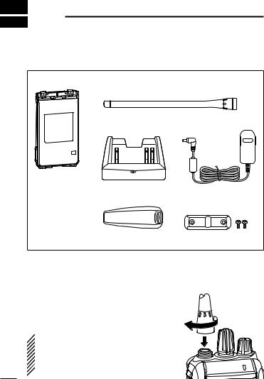
■ Supplied accessories
The following accessories are supplied with the transceiver.
Battery pack* |
Flexible antenna |
|
|
(This illustration is for the VHF type.) |
|
|
Battery charger* |
AC adapter* |
Belt clip |
Jack cover |
|
(with screws) |
*Not supplied, or the shape is different, depending on the version.
■Accessory attachments
D Flexible antenna
Connect the flexible antenna to the antenna connector.
 CAUTION:
• NEVER HOLD just the antenna
when carrying the transceiver.
• Transmitting without an antenna will  damage the transceiver.

|
ACCESSORIES |
1 |
|
D Belt clip |
|
|
1 |
To attach the belt clip: |
|
|
2 |
Slide the belt clip in the direction of the arrow until the belt clip |
|||
locks in place, and makes a ‘click’ sound. |
|
3 |
|
|
Belt clip |
|
4 |
|
|
|
|
|
|
|
5 |
|
Battery pack |
|
6 |
|
|
|
|
|
|
|
7 |
|
|
|
8 |
|
|
|
9 |
|
|
|
10 |
|
|
|
11 |
To detach the belt clip: |
|
|
12 |
q Remove the battery pack from the transceiver, if it is attached. |
|||
(p. 3) |
|
|
13 |
w Lift the tab up (q), and slide the belt clip in the direction of the |
14 |
||
arrow (w). |
|
|
|
|
|
|
|
q |
w |
|
15 |
|
16 |
||
|
|
||
|
|
|
|
|
|
|
17 |
Tab |
|
|
18 |
|
|
19 |
|
|
|
|
|
|
|
|
20 |
1 ACCESSORIES
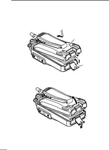
D Battery pack/case
To attach the battery pack/case:
q Fit the battery pack/case in the direction of the arrow (q), then close.
w Hook the latch until it makes a ‘click’ sound (w). q
Battery pack/case
 w
w
Latch
To remove the battery pack/case:
Unhook the latch (e), and lift up the battery pack/case in the direction of the arrow (r).
Be careful! The latch is tightly locked, so use caution when releasing it. DO NOT use your finger nail. Use the edge of a coin or screwdriver tip to carefully release it.
ACCESSORIES 1
 NEVER remove or attach the battery pack/case when the trans-
ceiver is wet or soiled. This may result in water or dust getting into
 the transceiver, battery pack/case, and may result in them being
 damaged.
 NOTE: Keep the battery terminals clean. It’s a good idea to clean
  the battery terminals once a week.
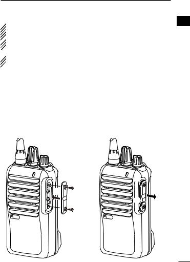
D Jack cover
Attach the jack cover when the optional equipment is not used.
To attach the jack cover: |
To detach the jack cover: |
q Attach the jack cover to the |
e Remove the screws with a |
[SP MIC] jack. |
phillips screwdriver. |
w Tighten the screws. |
r Detach the jack cover to con- |
|
nect the optional equipment. |
w |
e |
|
|
|
|
q |
|
|
|
e |
r |
w |
|
|
|
|
1
2
3
4
5
6
7
8
9
10
11
12
13
14
15
16
17
18
19
20
2 PANEL DESCRIPTION
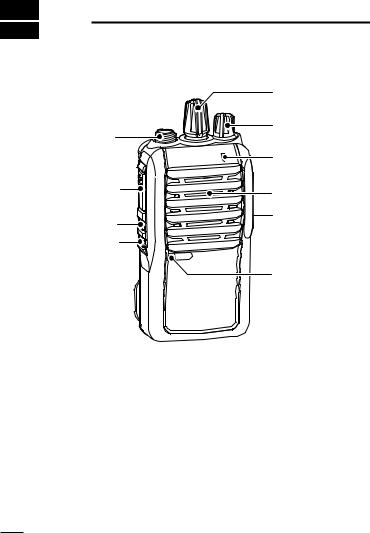
■ Front, top and side panels
|
qROTARY |
|
|
SELECTOR |
|
iANTENNA |
wVOLUME |
|
CONTROL |
||
CONNECTOR |
eLED INDICATOR |
|
|
||
uPTT SWITCH |
Speaker |
|
|
||
yUPPER KEY |
rSPEAKER- |
|
MICROPHONE |
||
tLOWER KEY |
||
JACK |
||
|
Microphone |
q ROTARY SELECTOR
Rotate to select the pre-programmed memory channels.
w VOLUME CONTROL [VOL]
Rotate to turn the power ON/OFF, and adjust the audio level.
PANEL DESCRIPTION 2
e LED INDICATOR (p. 7)
Lights red* while transmitting.
*When the optional battery case is attached, the LED indicator lights orange.
Lights green while receiving a signal, or when the squelch is open.
Lights/blinks orange when the matched 2/5-tone code is received, depending on the pre-programming.
r SPEAKER-MICROPHONE JACK [SP MIC]
Connect the optional speaker-microphone or VOX adapter cable.
Jack cover
NOTE: Attach the jack cover when the optional equipment is not used. (p. 4)
t LOWER KEY [Lower]
y UPPER KEY [Upper]
The desired function can be assigned by your dealer. (p. 8)
u PTT SWITCH [PTT]
Push and hold to transmit; release to receive.
iANTENNA CONNECTOR
Connect the antenna.
1
2
3
4
5
6
7
8
9
10
11
12
13
14
15
16
17
18
19
20
2 PANEL DESCRIPTION
■ LED indicator
The LED indicator indicates the status of various parameters of the transceiver as follows;
(Ref.; R=Red, G=Green, O=Orange)
• TX: Lights Red while transmitting a signal.
R *
• RX: Lights Green while receiving a signal.
G
• Call LED (ON): Turns ON while receiving a matched 2/5-tone.
O
• Call LED (Blink): Blinks while receiving a matched 2/5-tone.
O 
 O
O
• Fast/Slow scan: Blinks when the Fast/Slow scan is activated.
|
G |
|
G |
|
• Low Battery 1: You should charge the battery. (blinks slowly)
G 
 G
G
• Low Battery 2: You must charge the battery. (blinks fast)
|
G |
|
G |
|
G |
|
G |
• TX low Battery 1: Low Battery was detected during TX mode.
|
R* |
|
R* |
|
• TX low Battery 2: Very Low Battery was detected during TX mode.
|
R* |
|
R* |
|
R* |
|
R* |
|
• Channel Error: A non-programmed channel is selected.
R O R O R O R O R O R O R O R O
* Lights (or blinks) orange when the optional battery case is attached.

PANEL DESCRIPTION 2
■ Programmable function keys
The following functions can be assigned to the [Upper] and [Lower] programmable function keys.
Consult your Icom dealer or system operator for details concerning your transceiver’s programming.
SCAN A
Push to start and cancel the scanning operation.
When the Power ON scan function is turned ON, push to pause the scanning operation. The paused scan resumes after the specified time period has passed.
SCAN B
Push to start and cancel the scanning operation.
If the scan pauses for any reason, except being cancelled by this key, it will resume after a specified time period has passed.
PRIORITY A CHANNEL, PRIORITY B CHANNEL
Push to select the Priority A or Priority B channel.
PRIORITY A CHANNEL (REWRITE),
PRIORITY B CHANNEL (REWRITE)
Push to select the Priority A or Priority B channel.
1
2
3
4
5
6
7
8
9
10
11
12
13
14
15
Push and hold [Prio A (Rewrite)] or [Prio B (Rewrite)] for 1 sec. 16 to assign the operating channel to Priority A or Priority B chan-
nel, respectively.
MEMORY CHANNELS 1, 2, 3, 4
Push to directly select memory channel 1, 2, 3 or 4, if programmed. Consult your dealer for details.
17
18
19
20

2 PANEL DESCRIPTION
MONITOR, MONITOR (AUDIBLE)
Push to turn the CTCSS (DTCS) or 2/5-tone squelch Mute ON or OFF.
•Only during LMR operation, push to open any squelch functions, or deactivate any mute functions.
•Only during PMR operation, push to activate one or two of the following functions* on each channel.
-Push and hold to un-mute the channel (Audible mode).
-Push to mute the channel (Inaudible mode).
-Push to send a ‘reset code’ after the communication is finished. *Ask your dealer for details.
 NOTE: The un-mute condition may automatically return to
 the mute condition, after a specified time period.
Depending on the presetting, pushing and holding this key for 1 sec. cancels a scan.
LOCK
Push and hold to electronically lock all programmable keys except [Moni(Audi)], [Call] (including Call A and Call B), [Emergency], [Surveillance] and [Lone Worker].
LONE WORKER (p. 22)
Push to turn the Lone Worker function OFF.
Push and hold to turn the Lone Worker function ON.
•When the Lone Worker function is turned ON, and no operation is performed for the specified time period, the Emergency function is automatically turned ON.
HIGH/LOW (p. 20)
Select the transmit output power level temporarily or permanently, depending on the presetting.
• Ask your dealer for the output power level for each selection.

PANEL DESCRIPTION 2
TALK AROUND
Push to turn the Talk Around function OFF.
Push and hold to turn the Talk Around function ON.
•The Talk Around function equalizes the transmit frequency to the receive frequency for transceiver-to-transceiver communication.
WIDE/NARROW
Push to switch the IF bandwidth to Wide.
•The wide passband width can be selected from 20 or 25 kHz using the optional cloning software (PMR operation only). Ask your dealer for details.
Push and hold to switch the IF bandwidth to Narrow.
DTMF AUTODIAL
Push to transmit a programmed DTMF code.
CALL, CALL A, CALL B
Push to transmit a 2/5-tone code.
•Tone call transmission may be necessary before you call another station, depending on your signalling system.
•[Call A] and/or [Call B] keys may be available when your system employs selective ‘Individual/Group’ calls. Ask your dealer which call is assigned to each key.
1
2
3
4
5
6
7
8
9
10
11
12
13
14
15
16
17
18
19
20
10
Loading...