


40\
Hyundai 40, 52, 55, 70, 82 User Manual
...
User’s Guide
Benutzerhandbuch
Manuel d’utilisation
Manuale dell’utente
Guía de usuario
MODELS.
- Base Frame Model : 32", 40", 42", 46", 47", 52", 55", 70", 82"
- Kiosk Model : 46", 52", 70"

U.S.A.
U.S.FEDERAL COMMUNICATIONS COMMISSION RADIO FREQUENCY INTERFERENCE
STATEMENT INFORMATION TO THE USER
NOTE : This equipment has been tested and found to comply with the limits for a Class A
digital device pursuant to Part 15 of the FCC Rules.
These limits are designed to provide reasonable protection against harmful interference in a
residential installation.
This equipment generates, uses, and can radiate radio frequency energy and, if not installed
and used in accordance with the instructions, may cause harmful interference to radio
communications.
However, there is no guarantee that interference will not occur in a particular installation.
If this equipment does cause harmful interference to radio or television reception, which can
be determined by turning the equipment off and on, the user is encouraged to try to correct
the interference by one or more of the following measures:
Reorient or relocate the receiving antenna.
y
Increase the separation between the equipment and receiver.
y
Connect the equipment into an outlet of a circuit different from that to which the
y
receiver is connected.
Consult the dealer or an experienced radio/Monitor technician for assistance.
y
Changes or modication not expressly approved by the party responsible for
compliance could void the user’s authority to operate the equipment.
Connecting of peripherals requires the use of grounded shielded signal cables.

DECLARATION OF CONFORMITY
For the following product :
All of Digital sigange HYUNDAI IT provides
Manufactured at :
(factory name, address)
1. Hyundai IT Corp. 1229 In-ri, Apo-eup Gimcheon, Gyeongsangbuk-do 740-860 Rep. of Korea
2. Hyundai IT Corp. San 136-1 Ami-ri, Bubal-eub, Ichon-si, Kyungki-Do, 467-860 Rep. of Korea
We herewith confirmed to comply with the requirements set put in the Council Directive on the
Approximation of the Lows of the Member States relating to Electromagnetic Compatibility Directive
(89/336/EEC), Low-Voltage Directive(73/23/EEC , 93/68/EEC) . For the evaluation regarding the Directives,
the following standards were applied:
EN60065 : 2002
EN55022 : 1998+A1 : 2000 +A2 : 2003 CLASS A
EN55024 : 1998+A1 : 2001 +A2 : 2003
EN 61000-3-2 : 2000 +A2 : 2005
EN 61000-3-3 : 1995 +A1 : 2001 +A2 : 2005

DIGITAL SIGNAGE
Contents
Major features ........................................................................................................... 2
Safety Information .................................................................................................... 2
Be sure to understand .............................................................................................. 5
Check the product list ............................................................................................... 6
Proper location for product installation .................................................................. 7
Portrait Mode ............................................................................................................7
Installing a Bracket(Option) ..................................................................................... 8
Installing a Wall Mount(Option) .............................................................................. 9
Title and function of each part .............................................................................. 10
How to Connecting Kiosk ....................................................................................... 13
How to Connecting Digital RGB(HDMI) ................................................................. 14
How to Connecting analog RGB(PC D-SUB) .......................................................... 16
How to Connecting the component(Option) ........................................................ 18
How to Connecting the the video(Option) ........................................................... 20
Adjusting OSD and explanation of its function ...................................................21
Diagnosis ................................................................................................................. 40
Specifications ..........................................................................................................42
* REMOTE CONTROL / RS232C COMMAND SPEC
English

DIGITAL SIGNAGE
Major features
Safety Information
This product has been designed to enable the user ease of use, and display information
effectively and conveniently.
• TFT LCD Module adopted
• Vivid digital color display
• OSD control function
• Automatic Image control
• Automatic temperature control
• Analog/Digital RGB(HDMI) input and output
• Y Pb Pr/AV input and output
• Built in multi-vision function
This product is designed to ensure user's safety.
Avoid the following items to prevent serious electric shot and other dangers.
- Do not place wet objects on or around the product or the power cord.
- Do not cover or insert anything over or into the ventilation openings.
- Do not place in a location where damage can be caused by oil, smoke, high temperature,
high humidity, dust etc.
- The product is not suitable for use at visual display workplaces according to §2 of the German
Ordinance for Work with Visual Display Units.
-
The main plug of the power supply cord shall remain readily operable.
- An apparatus with CLASS I construction shall be connected to a Mains socket outlet
with a protective earthing connection.
- Make sure that the power cord and other cables are correctly plugged in.
2

DIGITAL SIGNAGE
- Plug the power cord correctly into the end, do not wobble/jiggle, it may cause electric shock fire.
- Do not touch the power cord with wet hands, it may cause electric shock.
- Overloaded AC outlets and extension cables are as dangerous as the power cord being damaged,
call service engineer for replacement as it may cause electric shock or fire.
- Do not use multiple devices in a single power outlet, it may cause overheating or fire.
- Do not use or place sharp objects near the LCD surface, as this can cause damage to the screen itself.
- When cleaning the LCD screen / Surface, do not use chemical cleaning products as this can
seriously damage the special coatings on the screen. Only use water to dampen a soft cloth and
lightly clear the screen.
- Over time dust deposits can build up inside the product, this can cause the product to overheat
thus causing premature malfunction or fire. Please do not attempt to clean the inside of the
product yourself, please contact the local service agent.
- Do not use alcohol or strong chemical solvent such as methyl, ethyl or a Isopropyl.
- In the case of cleaning, be sure to remove the power cord and wipe with a soft dry fabric.
- Keep batteries for the remote control out of children's sight.
- Batteries should be inserted using the correct polarity (+,-).
- Use only new batteries, do not mix old & new.
- Place unit on a stable bracket or surface.
- More than 2 people should work together when moving or installing.
- Do not hang on or jump to the product or mounting rack.
- When the product is left unused for a long time, be sure to unplug the power cord.
- In the case of damage or breakage do not attempt to self repair, please contact local service
engineer.
English
3

DIGITAL SIGNAGE
- In case of Kiosk Model, keep installing the product on the flat location and fixing the wheels
not to move itself or fall down.
- On Kiosk Model, make sure to turn off the power before connecting cables.
- This manual contains general instructions for the display products only so refer to the
provided CD-ROM manual and the driver installation manual for the driver installation
instructions for touch screen and/or touch screen itself.
- The apparatus shall not be exposed to dripping or splashing and that no objects filled with
liquids, such as vases, shall be placed on the apparatus.
- Shall be connected to a MAINS socket outlet with a protective earthing connection.
- The disconnect device shall remain readily operable.
- The socket-outlet shall be installed near the equipment and shall be easily accessible.
- Use only with a cart, stand, tripod, bracket, or table specified by the
manufacturer, or sold with the apparatus. When a cart is used, use
caution when moving the cart/apparatus combination to avoid injury
from tip-over.
4

DIGITAL SIGNAGE
Be sure to understand
Image quality of the product
CAUSE
Due to the nature of LCD's property, Afterimage can occur. Afterimage appears when
identical frames / images are displayed continuasly. If displayed for prolonged periods of
time this can become permanent.
PREVENTION
When you display a freeze frame for a long time, lower the brightness and contrast
(Brightness, 70/ Contrast, 80). Also it can be prevented by using moving frame.
COUNTERMEASURES
Temporary afterimage can be alleviated by displaying white or moving frame about 10
hours.(But, permanent afterimage cannot be disappeared according to the property of
LCD) This method is used to remove temporary afterimage that may occur after
displaying a still frame for a certain time.
It can take several minutes or hours to remove afterimage according to the severity. In
the case that your cannot avoid displaying identical still image continuously, you can
prevent it by displaying moving image for 2 or 3 minutes in every hour. As the brightness
of still image and time of display are the cause of afterimage, you are recommended to
lower the brightness in that case.
Above problem shall not be covered by warranty.
!
English
5

DIGITAL SIGNAGE
Check the product list
Please check the following components provided with the product after you open the box.
Base Frame Type
Kiosk Type (Portrait)
please check the following components provided with the product after you open
!
the box and contact the dealer if any missing.
** The contents may vary depending on models and sometimes the contents may be attached on the product.
Kiosk Type (Landscape)
Remote control & batteries Power Cord
User's manual D-SUB Cable
HDMI to DVI Cable (Option) HDMI cable
RS232C Cable (Option)
6

DIGITAL SIGNAGE
Proper location for
product installation
Portrait Mode
1. Locate the product at least 30cm away from the electric appliance or heating product.
2. The product must be placed at least 10cm away from the wall and ground.
3. Keep the product out of direct ray of light and locate screen not to be reflected by the
sunlight.
4. Make sure the mounting rack firmly tightened before installation.
Please take extra care during installation, it is possible to cause damage if the unit is
!
handled badly or knocked.
- Only on some models.
- When installing in portrait mode, rotate the monitor clockwise
English
7

DIGITAL SIGNAGE
Installing a Bracket
(Option)
- The contents may vary depending on models
8

DIGITAL SIGNAGE
580 mm
1026 mm
Installing a Wall Mount
(Option)
- Only install the product on a vertical wall.
- To ensure product performance and avoid damage, it is
strongly recommended that you avoid the following
installation locations :
Near the sprinkler sensor, Near the heater
Where vibration or shock may occur
BOLT-HEX,(SP/PL)MC(+)8*20
Anchor
Near high-tension wires
- Use an appropriate installation method for the material of the
wall. Check the safety of the wall surface first and reinforce the
wall if the wall strength is not enough for installation.
- Do not install the wall mount inside the wall.
Horizontal adjustment screw
English
BOLT-HEX,TT(+)4*60(L)
9

DIGITAL SIGNAGE
POWER
SOURCEMENU
SELECT
VOL
Title and function of each
part
Control Panel
Remote control receiving sensor.
1
Power display LED red-stand by/ Green-working.
2
OSD button.
3~ 0
Power button ; to turn the power on or off.
3
Input selection button : to select other connected
4
device.
3 4 5 6 7 8 9
Menu button : to display menu or exit from the menu.
5
select button.
6
To move down in OSD menu.
7
To move up in OSD menu.
8
To move left and control the volume down in OSD menu.
9
To move right and control the volume up OSD menu.
0
0
1 2
Base Frame Type (Front)
Kiosk Type (Rear)
10
** The locations of OSD board and remote control receiving sensor may vary depending on models.

DIGITAL SIGNAGE
Terminal panel
AC IN
1
AC POWER SWITCH
2
HDMI IN
3
HDMI OUT
4
SPEAKER OUT
5
PC D-SUB IN
6
2
1
3
** The locations of connectors may vary depending on models.
- The items no. 12–17 are optional items.
- When you select the "Source"button on the remote control, the "Source"menu of the "Option" item
is displayed.
PC D-SUB OUT
7
UPGRADE
8
PC AUDIO IN
9
RS-232C OUT
0
RS-232C IN
!
COMPONENT IN (Y/Pb/Pr)
@
5
6
74
8
9
0
!
COMPONENT OUT (Y/Pb/Pr)
#
CVBS IN
$
CVBS OUT
%
COMPONENT AUDIO IN (L/R)
^
COMPOSITE AUDIO IN (L/R)
&
^
$
@
&
%
#
English
11
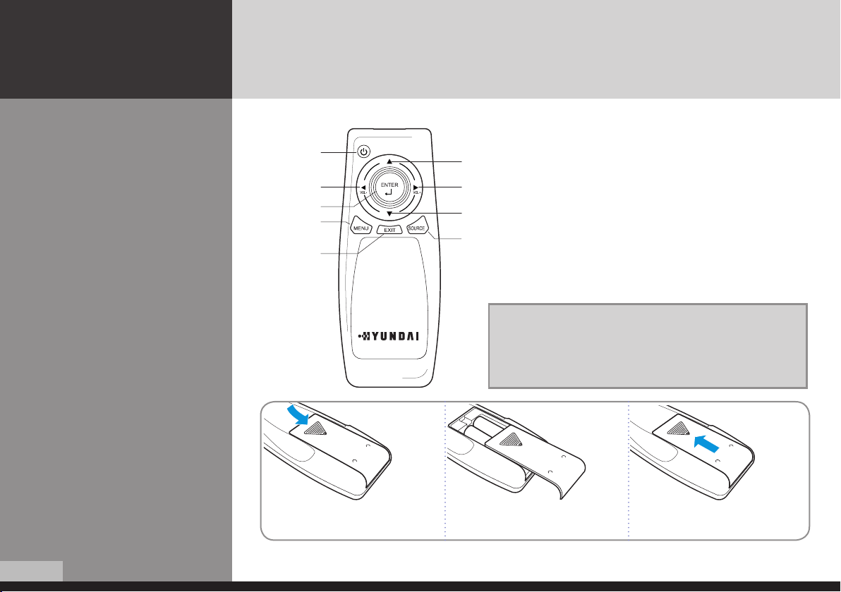
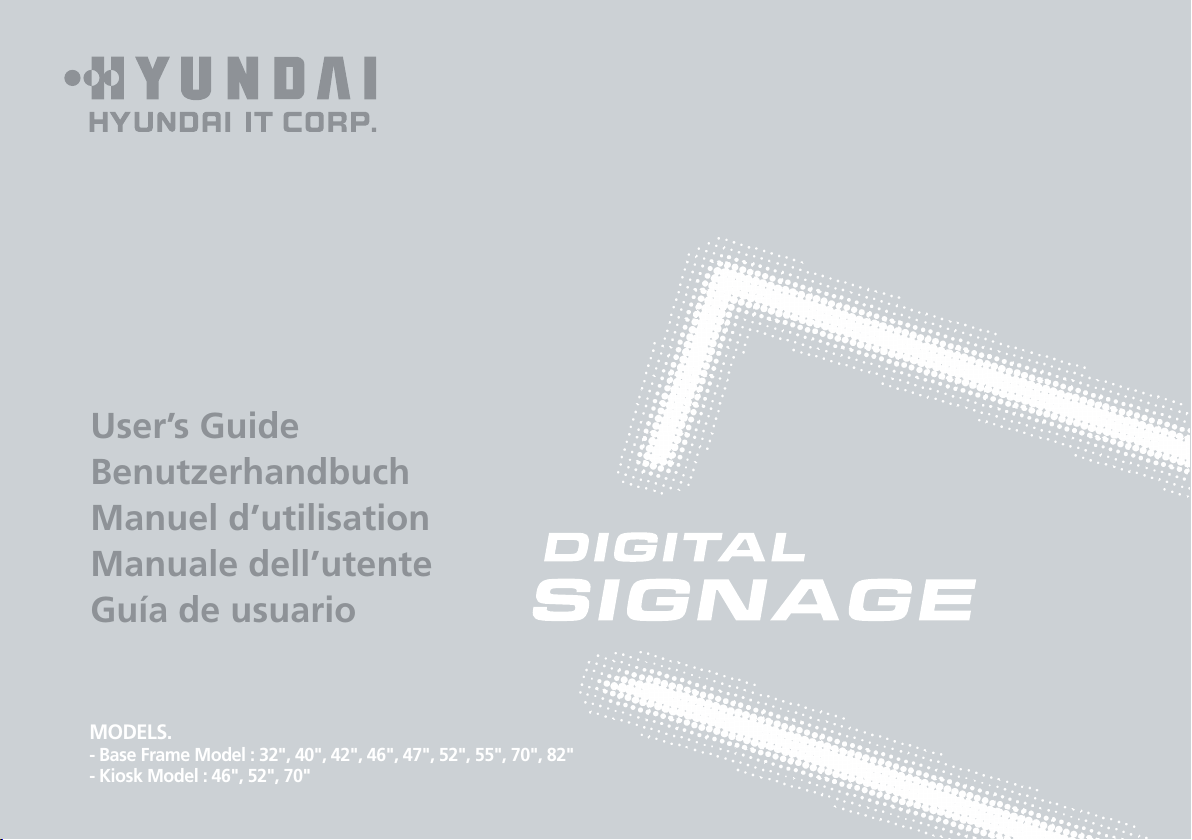
Remote control
How to insert batteries
DIGITAL SIGNAGE
1
3
6
7
8
2
4
5
9
1 2 3
1
2
3
4
5
6
7
8
9
[TIP] If it doesn’t need to control display by a remote-controller,
press button of remote-controller in order following.
MENU → SOURCE → EXIT → ▼ → ENTER
* Press button once again in order above so that original condition
is returned.
To turn the power on or off.
Move up in OSD menu.
To move left or control the volume down in OSD menu.
To move right or control the volume up in OSD menu.
To move down in OSD menu.
Select in OSD menu.
Display the menu screen.
Close the menu screen.
Convert the input signal.
12
Pull while pressing at rear lid. Insert the batteries into proper polarities
(+,-).
Use after the lid closed.

How to Connecting
Kiosk
DIGITAL SIGNAGE
PC or Player
(Satellite receiver,
Camcorder etc.)
English
13
 Loading...