

HP StoreOnce 3620, StoreOnce 3640, StoreOnce 5200, StoreOnce 5250, StoreOnce 5650 Installation Manual
Page 1

HPE StoreOnce 3620, 3640, 5200, 5250, and 5650 Systems Installation Guide
Abstract
This guide provides instructions for installing HPE StoreOnce 3620, 3640, 5200, 5250, and
5650 Systems, including the optional hardware and capacity upgrade kits. Use the
instructions in this guide to install a new StoreOnce System or add a capacity upgrade kit to
an existing StoreOnce system. This guide is for HPE StoreOnce System administrators.
Part Number: BB954-80021b
Published: February 2019
Edition: 3
Page 2

©
Copyright 2018-2019 Hewlett Packard Enterprise Development LP
Notices
The information contained herein is subject to change without notice. The only warranties for Hewlett
Packard Enterprise products and services are set forth in the express warranty statements accompanying
such products and services. Nothing herein should be construed as constituting an additional warranty.
Hewlett Packard Enterprise shall not be liable for technical or editorial errors or omissions contained
herein.
Confidential computer software. Valid license from Hewlett Packard Enterprise required for possession,
use, or copying. Consistent with FAR 12.211 and 12.212, Commercial Computer Software, Computer
Software Documentation, and Technical Data for Commercial Items are licensed to the U.S. Government
under vendor's standard commercial license.
Links to third-party websites take you outside the Hewlett Packard Enterprise website. Hewlett Packard
Enterprise has no control over and is not responsible for information outside the Hewlett Packard
Enterprise website.
Acknowledgments
Intel®, Itanium®, Pentium®, Xeon®, Intel Inside®, and the Intel Inside logo are trademarks of Intel
Corporation in the U.S. and other countries.
Microsoft® and Windows® are either registered trademarks or trademarks of Microsoft Corporation in the
United States and/or other countries.
Adobe® and Acrobat® are trademarks of Adobe Systems Incorporated.
Java® and Oracle® are registered trademarks of Oracle and/or its affiliates.
UNIX® is a registered trademark of The Open Group.
Page 3

Contents
Overview.................................................................................................. 6
HPE StoreOnce 3620 System.................................................................8
HPE StoreOnce 3640 System...............................................................20
Read this before installing StoreOnce Gen4 Systems..................................................................6
StoreOnce Management Console supported browsers................................................................ 7
HPE StoreOnce 3620 System...................................................................................................... 8
HPE StoreOnce 3620 System installation process overview........................................................8
Preparing the rack for the StoreOnce 3620 System..................................................................... 8
HPE StoreOnce 3620 System handling requirements..................................................................9
Installing the StoreOnce 3620 System..........................................................................................9
Configuring a newly installed StoreOnce 3620 system...............................................................13
Installing the StoreOnce 3620 Capacity Upgrade Kit..................................................................16
HPE StoreOnce 3640 System.................................................................................................... 20
HPE StoreOnce 3640 System installation process overview......................................................20
Preparing the rack for the StoreOnce 3640 System................................................................... 20
HPE StoreOnce 3640 System handling requirements................................................................21
Installing the StoreOnce 3640 System server.............................................................................22
Installing the capacity upgrade enclosures during the initial system installation........................ 26
Configuring a newly installed StoreOnce 3640 system...............................................................33
HPE StoreOnce 5200 System...............................................................37
HPE StoreOnce 5200 System.................................................................................................... 37
HPE StoreOnce 5200 System installation process overview......................................................37
Preparing the rack for the StoreOnce 5200 System................................................................... 37
HPE StoreOnce 5200 System handling requirements................................................................38
Installing the StoreOnce 5200 System........................................................................................39
Configuring a newly installed StoreOnce 5200 system...............................................................48
HPE StoreOnce 5250 and 5650 Systems............................................ 52
HPE StoreOnce 5250 and 5650 Systems...................................................................................52
HPE StoreOnce 5250 and 5650 System installation process overview......................................53
Preparing the rack for the StoreOnce 5250 and 5650 Systems................................................. 53
HPE StoreOnce 5250 and 5650 Systems handling requirements.............................................. 57
Installing the StoreOnce 5250 and 5650 base systems..............................................................57
Configuring a newly installed StoreOnce 5250 or 5650 system................................................. 68
Installing capacity upgrade kits...........................................................71
HPE StoreOnce 3620 24 TB Capacity Upgrade Kit....................................................................71
Capacity upgrade kit contents..........................................................................................71
Enabling maintenance mode when using StoreOnce Remote Support........................... 71
Installing the StoreOnce 3620 Capacity Upgrade Kit.......................................................72
Completing the capacity upgrade.....................................................................................74
3
Page 4

HPE StoreOnce 3640 48 TB Capacity Upgrade Kit....................................................................74
Introduction.......................................................................................................................74
Installing and connecting the capacity upgrade enclosures.............................................76
HPE StoreOnce 5200 48 TB Capacity Upgrade Kit....................................................................83
Introduction.......................................................................................................................83
Installing and connecting the capacity upgrade enclosures.............................................85
HPE StoreOnce 5250 and 5650 Capacity Upgrade Kits.............................................................97
Introduction.......................................................................................................................97
Installing the Capacity Upgrade Kit, BB974A and BB976A disk pack............................101
Installing the Drawer Upgrade Kit, BB966A and BB968A enclosure............................. 106
Cabling upgrade enclosures...........................................................................................114
Completing the capacity upgrade............................................................................................. 120
Redeeming and adding the licenses.............................................................................. 120
Scanning and configuring storage..................................................................................121
Checking hardware and firmware.................................................................................. 121
Disabling maintenance mode.........................................................................................121
Configuring a newly installed system...............................................122
Verifying the hardware installation............................................................................................ 124
Initial StoreOnce network configuration.................................................................................... 125
Licensing...................................................................................................................................125
User roles and types................................................................................................................. 126
StoreOnce Remote Support .....................................................................................................127
Configuring remote support............................................................................................127
iLO network name and iLO password.......................................................................................128
Configuring media servers to use StoreOnce Catalyst............................................................. 128
Drivers for StoreOnce VTL devices on client servers............................................................... 129
Warranty details........................................................................................................................ 129
Fibre Channel with StoreOnce Systems................................................................................... 130
Fibre Channel hardware requirements...........................................................................130
Supported Fibre Channel connections...........................................................................130
Installing optional hardware.............................................................. 132
Optional hardware kit contents................................................................................................. 132
Installation scenarios................................................................................................................ 132
PCIe slot allocation for optional hardware cards.......................................................................133
Install PCIe cards .....................................................................................................................133
Safety considerations.....................................................................................................133
Required tools................................................................................................................ 134
Prerequisites for installing PCIe cards........................................................................... 134
Enabling maintenance mode when using StoreOnce Remote Support......................... 135
Powering down the StoreOnce System......................................................................... 135
Removing cables, extending the server from the rack, and removing the access
panel...............................................................................................................................135
Removing the PCIe riser cage and installing the PCIe card.......................................... 136
Completing the PCIe card installation............................................................................ 138
Installing SFP transceivers, if necessary, and connecting to the network or SAN......... 138
Complete the new hardware installation using the StoreOnce Management Console............. 140
Redeeming and applying the optional hardware license................................................140
Troubleshooting optional hardware installation.........................................................................140
Troubleshoot error messages for optional hardware......................................................140
Removing and replacing optional hardware cards......................................................... 141
4
Page 5

The Initialization Console...................................................................142
Accessing the Initialization Console..........................................................................................142
Determining the initial DHCP network address.........................................................................142
Configuring the initial system networking..................................................................................142
Resetting the local Admin password.........................................................................................143
Changing the Initialization Console password.......................................................................... 143
Enabling support access...........................................................................................................143
StoreOnce websites............................................................................145
Other sources of information for HPE StoreOnce Systems...................................................... 145
Support and other resources.............................................................146
Accessing Hewlett Packard Enterprise Support....................................................................... 146
Accessing updates....................................................................................................................146
Customer self repair..................................................................................................................147
Remote support........................................................................................................................ 147
Warranty information.................................................................................................................147
Regulatory information..............................................................................................................148
Documentation feedback.......................................................................................................... 148
5
Page 6

Overview
Use the procedures in this guide to install, configure, or upgrade an HPE StoreOnce 3620, 3640, 5200,
5250, or 5650 System.
• Install a new system, including any capacity upgrade kits and optional features.
◦
Installing the StoreOnce 3620 System
◦ Installing the StoreOnce 3640 System
◦ Installing the StoreOnce 5200 System
◦ Installing the StoreOnce 5250 and 5650 Systems
• Install and configure a capacity upgrade kit for an existing system.
◦ HPE StoreOnce 3620 24 TB Capacity Upgrade Kit
◦ HPE StoreOnce 3640 48 TB Capacity Upgrade Kit
◦ HPE StoreOnce 5200 48 TB Capacity Upgrade Kit
◦ HPE StoreOnce 5250 and 5650 Capacity Upgrade Kits
• Configure a new system after it has been installed using the start here guide.
Configuring a newly installed system
• Install StoreOnce Gen4 optional hardware in an existing system.
Installing StoreOnce Gen4 optional hardware
Read this before installing StoreOnce Gen4 Systems
The HPE StoreOnce 3620, 3640, 5200, 5250, and 5650 Systems are the fourth generation of StoreOnce
Systems. These systems are designed to be simpler to install and configure than the previous generation
appliances.
• Systems are preconfigured in manufacturing. They ship with all capacity upgrades and optional
hardware cards already installed, licensed, and available for use.
• Storage is preconfigured in manufacturing so the systems arrive with functional RAID sets and file
systems.
• The systems auto-configure on startup; little manual intervention is required.
• User interface and status reporting are designed for maximum ease of use and clarity.
• Storage enclosures are labeled to show the server that they attach to and their JBOD number.
• Cables are labeled with their installation location.
• Hard disk labeling kits make it easier to return hard disks to their proper slots during installation or
maintenance procedures.
If a disk is not installed in its original slot, the system will fail to start.
Because they are preconfigured, the fourth-generation StoreOnce systems must be installed exactly as
described in this guide.
6 Overview
Page 7
• Storage enclosures must be connected to the same server they were manufactured with.
• Cables must be connected to the same server and/or storage enclosure they were manufactured with.
• Hard disks are preconfigured and must remain installed or returned to the same disk slots they arrived
in.
You can remove the hard disks to make the enclosures lighter and easier to install. All hard disks must
be returned to their original slots before the system is powered on. Failure to return each disk to its
proper location will result in the system failing to start.
Label the disks with the provided label kits before removing them from the enclosure for ease of
installation and maintenance.
TIP: If an HPE StoreOnce 3620, 3640, 5200, 5250, or 5650 system does not start up correctly after
installation, the problem is probably with the way it was installed. Check the installation first before
attempting to debug the system.
StoreOnce Management Console supported browsers
For the most current compatibility information including browser versions, see the HPE StoreOnce
Support Matrix.
• Internet Explorer
• Mozilla Firefox
• Google Chrome
Overview 7
Page 8

HPE StoreOnce 3620 System
HPE StoreOnce 3620 System
Base system
The HPE StoreOnce 3620 base system consists of a server with preconfigured storage on six hard disks
of 4 TB each.
Capacity upgrade options
BB960A: HPE StoreOnce 3620 24 TB Capacity Upgrade Kit
Six 4 TB preconfigured disks to add to the server for a maximum configuration of 12 hard disks in the
system.
Optional hardware
Four PCIe slots are available for optional hardware.
• BB984A: StoreOnce 10GbE-T 2-port Ethernet card
• BB982A: StoreOnce 10/25Gb SFP 2-port Ethernet card
• BB986A: StoreOnce 16Gb Fibre Channel 2-port card
• BB990A: StoreOnce 32 Gb Fibre Channel 2-port card
HPE StoreOnce 3620 System installation process overview
Procedure
1. Prepare the rack.
2. Verify system handling requirements.
3. Install the StoreOnce 3620 System.
4. Configure the newly installed system.
Preparing the rack for the StoreOnce 3620 System
Procedure
1. Ensure that the rack has sufficient space for the system.
• The base system requires 2U.
• The system does not support capacity upgrade enclosures.
2. Install two power cords for the server.
8 HPE StoreOnce 3620 System
Page 9
HPE StoreOnce 3620 System handling requirements
Component Rack space Weight
System server 2U 25 kg (55 lbs)
Capacity upgrade kit N/A 4.5 kg (10 lbs)
CAUTION: Use extreme care when installing and pulling units from the rack. Unattached units can
slip and fall, damaging the StoreOnce System or causing personal injury.
• Always use at least two people to lift and locate the server or enclosure into the rack.
• Hewlett Packard Enterprise is not responsible for any damage or injury caused by mishandling
the StoreOnce System.
TIP: Hard disks are preconfigured and must remain installed or returned to the same disk slots they
arrived in.
You can remove the hard disks to make the enclosures lighter and easier to install. All hard disks
must be returned to their original slots before the system is powered on. Failure to return each disk
to its proper location will result in the system failing to start.
Label the disks with the provided label kits before removing them from the enclosure for ease of
installation and maintenance.
Installing the StoreOnce 3620 System
Prerequisites
Required tools:
• Torx T25 screwdriver
• A monitor and USB keyboard or a KVM for initial network configuration
Procedure
1. Verify that you received the following components:
• StoreOnce System server
• Rail kit
• Security bezel
• Two power cables
• Two network cables
2. Record the iLO default network information from the label on top of the server.
iLO user name:________________________
iLO network name:_____________________
iLO password:_________________________
3. Install the optional PCIe cards, if necessary.
HPE StoreOnce 3620 System 9
Page 10
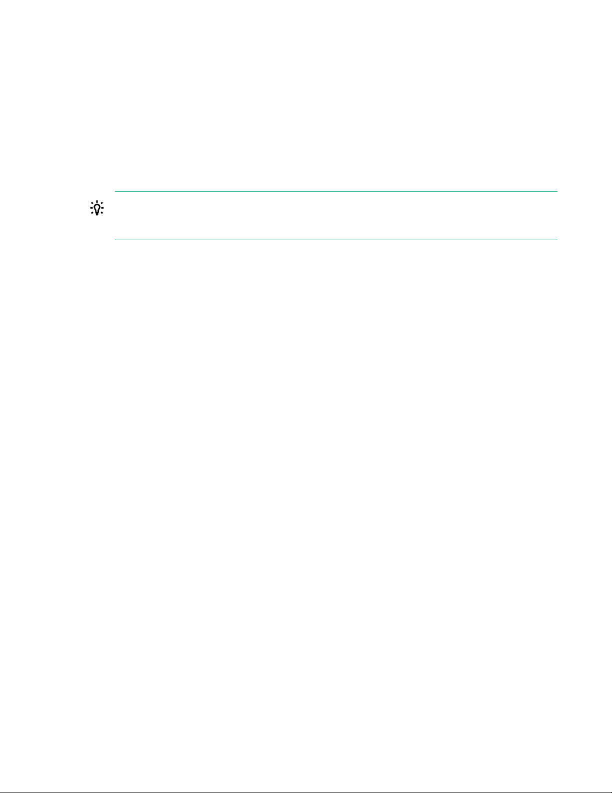
If the optional PCIe cards were ordered with the system, they have been preinstalled. If the cards
1 2 3 4 5 6
were ordered separately, install them now.
Figure 1: PCI slot numbering
a. Install network cards starting in PCI slot 1 and then additional network cards in slots 2, 4, and 5 in
that order.
b. Install FC cards starting at PCI slot 5 and then additional FC cards in slots 4, 2, and 1 in that
order.
c. Verify that the correct SFP+ transceivers are fitted, if necessary.
For detailed installation instructions, see Install PCIe cards .
4. Install the server in the rack.
a. Install the rail kit for the StoreOnce server.
See the installation instructions that are provided with the rail kit.
b. Insert the two locking nuts for the server into the rack; one on each front column.
c. Install the server into the rack and secure it using the thumbscrews on the front bezel of the
server.
5. Attach the security bezel to the front of the server.
a. Insert the security bezel right tab into the slot on the chassis and then rotate the bezel to close.
b. Lock the bezel.
10 HPE StoreOnce 3620 System
Page 11
The key to lock the bezel is attached to the back of the security bezel. One key is supplied.
6. Connect the cables.
a. Connect the power cables.
Connect each power cable to a separate PDU in the rack.
b. Connect a network cable to LAN port 1.
c. Connect a network cable to the iLO port (recommended).
d. Connect a VGA monitor and a USB keyboard for initial configuration.
7. Power on the StoreOnce System (the power button is on the front of the server).
HPE StoreOnce 3620 System 11
Page 12
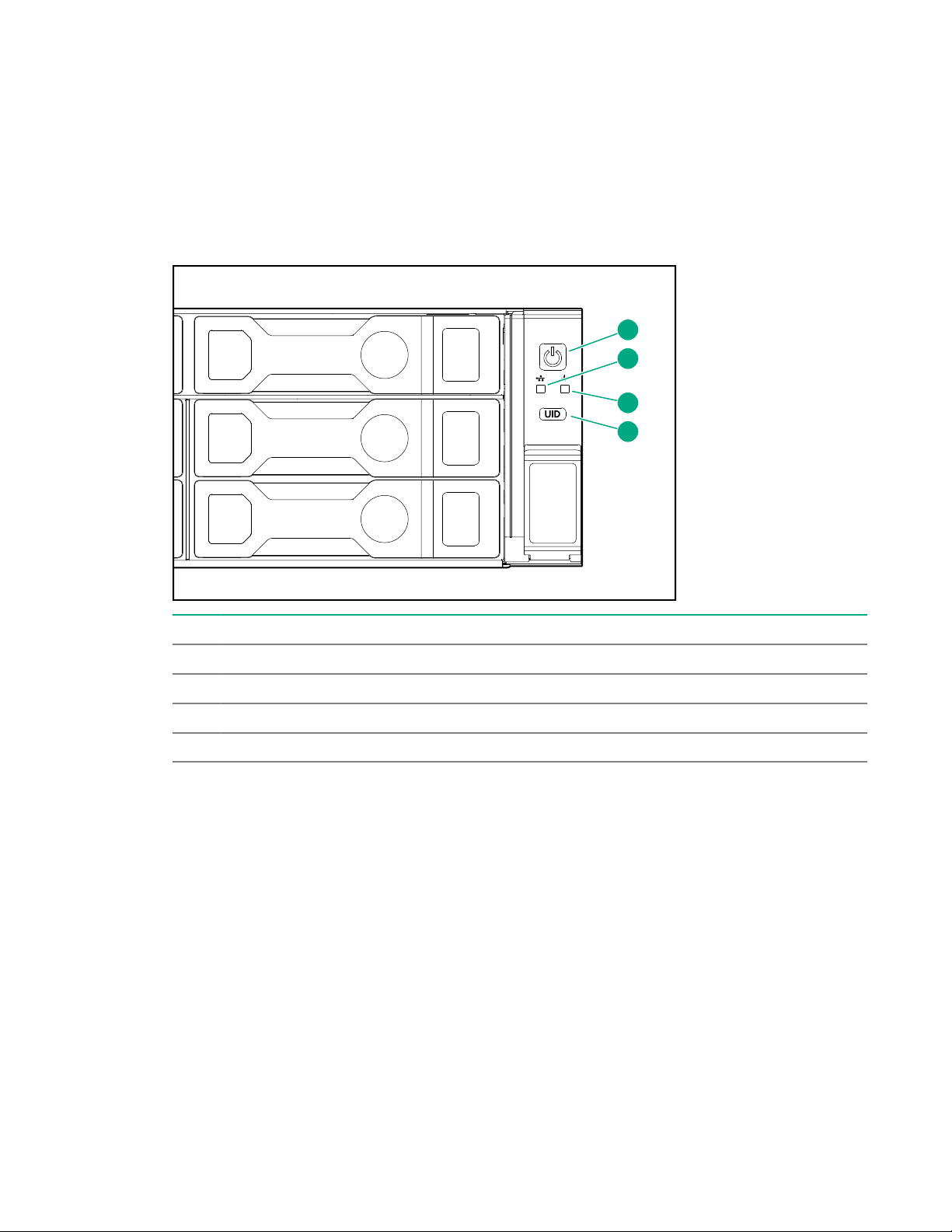
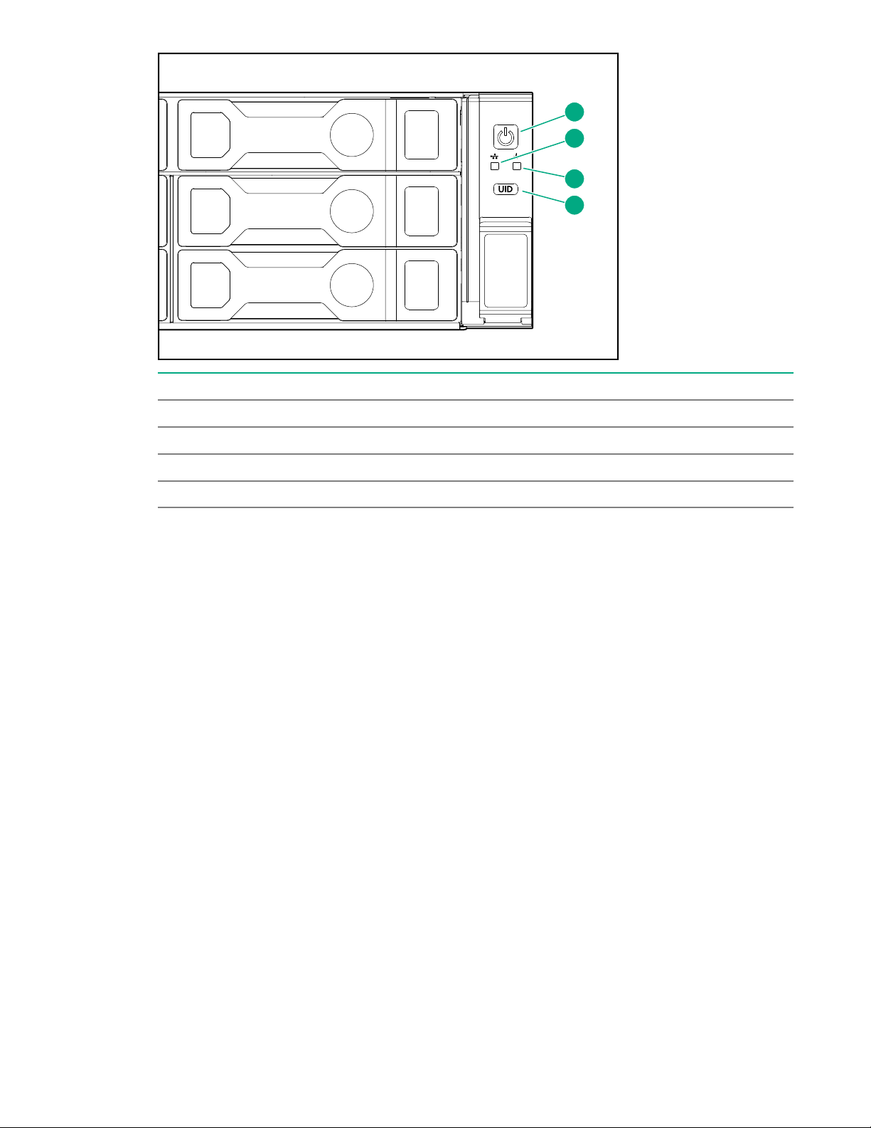
• The power button LED flashes green at the start of the power-on sequence and then turns solid
1
2
3
4
green.
• The system health LED flashes green at the start of the power-on sequence and then turns solid
green.
• If LAN port 1 is connected to an active link, the NIC status LED will also begin to flash green
when the StoreOnce System is powering up.
• While configuring the system using iLO virtual console, the UID LED flashes blue.
Item Description
1 Power LED and on/off button
2 NIC status LED
3 System health LED
4 UID LED
8. Connect the network.
If the system is not connected to a network with DHCP, configure iLO during bootup.
If the system is connected to a network with DHCP, iLO will work without additional configuration.
Most iLO settings must be configured during bootup. The iLO network options can also be configured
with the System Manager.
a. Press F9 System Utilities.
b. Navigate to System Configuration > iLO 5 Configuration > Network Options.
c. Configure the iLO network options and note the details.
iLO IP address:___________________________
iLO subnet mask:_________________________
iLO gateway:_____________________________
12 HPE StoreOnce 3620 System
Page 13

9. Configure the basic network.
By default, the system will have already attempted to obtain a DHCP address on LAN port 1. If you
already know the IP address that was assigned over DHCP, this step is optional.
a. Log in using the default user name and password.
Default user name: console
Default password: changeme
b. Change the console password to proceed.
Choose a secure password with at least eight characters that is memorable to you.
c. To configure a static address for LAN port 1 (eno1), select the Configure initial network
option from the console menu.
If the system obtained an IP address through DHCP, it is displayed. Note the DHCP assigned IP
address or the static address details.
IP address:______________________________
Prefix length:_____________________________
Gateway:________________________________
DNS:________________________________
You can remove the console display and keyboard.
10. Open a web browser and use the IP address from the previous step to access the StoreOnce
system.
The First Time Setup wizard is automatically displayed. Use the First Time Setup wizard to configure
the system for use.
The setup steps include:
• Setting the Administrator Password.
• Setting the Console Password.
• Setting basic System Information such as the system name (host name), location, and contact
information.
• Setting the System Date & Time. You can set the date and time manually, or synchronize the
date and time with a network time server.
• Configuring Storage. The wizard detects the factory installed storage. The wizard also enables
you to configure additional storage capacity that you might have installed. The wizard also reports
issues with additional storage, for example, when additional storage is not installed in the correct
location.
• Configuring Remote Support.
Configuring a newly installed StoreOnce 3620 system
For additional information and instructions on each step, see the online help or user guide.
HPE StoreOnce 3620 System 13
Page 14
Procedure
1. Log on to the StoreOnce Management Console. Review and update the settings that were
configured with the First Time Setup Wizard.
• Administrator password
• System information, such as system, location, and contact information
• System date and time, or NTP configuration
• Storage configuration
• Remote Support configuration
• Console password
2. Complete the network configuration.
On the main menu, select Settings. In the Hardware section, click the Networking panel.
For additional information, see Initial StoreOnce network configuration.
3. Redeem licenses, if necessary. Capacity or feature licenses ordered with the system will be
preinstalled. If ordered separately redeem them now.
The capacity upgrade kit includes a license entitlement certificate. The certificate is a paper
document containing the information necessary to obtain your unique LTU (License to Use) key file
from the HPE Licensing website.
NOTE: Redeem licenses individually to obtain a license key file for each upgrade kit. Do not merge
multiple entitlements to redeem a single license key file.
IMPORTANT: You must add the licenses before expanding the capacity of the StoreOnce
System. The storage expansion process will not configure unlicensed storage attached to the
system.
a. On the main menu, select Settings.. From the System panel, select the License Management.
b. On the Overview tab, make a note of the Locking ID (Serial Number).
If you are managing the system through the federation lead, ensure that you are viewing the
correct system.
c. Go to the HPE Licensing website, as directed in the License Entitlement Certificate.
d. Log in using your HPE Passport user ID and password.
e. Enter your Entitlement Order Number to search for your license.
f. Follow the steps to activate and obtain your license.
You can obtain the license file by downloading it directly from the website or from an email with
a .zip attachment.
g. Return to the License Management screen in the StoreOnce Management Console.
h. Expand the Actions menu ( ), click the Add License icon ( ), and then follow the onscreen
instructions.
14 HPE StoreOnce 3620 System
Page 15

4. Configure licenses, if necessary. Capacity or feature licenses ordered with the system will be
preinstalled. If ordered separately configure them now.
a. On the main menu, select Settings.
b. In the Systems section, click the License Management panel.
• To view a license summary, click the Overview tab.
• To view a list of the installed licenses, click the Licenses tab.
For additional information, see Licensing.
5. Configure user accounts.
a. On the main menu, select Settings.
b. In the User Management section, click the Users and Groups panel panel.
• To add a user or group, select Add user or group on the Actions menu.
• To edit a user, click the user name.
• To remove a user, click the user name and then click Remove.
For additional information, see User roles and types.
6. Configure StoreOnce email alerts.
To display the configured email alerts, select Notifications from the Settings menu item.
7. Configure SNMP.
a. On the main menu, select Settings.
b. In the Notifications section, click the SNMP panel.
• To view summaries of the SNMP configuration, click the Overview tab. To view lists of the
items in the summaries, click the graphic segments and legends.
• To configure SNMP, select the tabs for Agent Setup, Trapsinks, and Users.
8. Apply an SSL certificate.
a. On the main menu, select Settings.
b. In the Security section, click the Certificates panel.
c. On the Certificates screen, select Generate CSR on the Actions menu.
9. Expand storage, if necessary. Capacity upgrades ordered with the system will have already been
configured. If capacity upgrades were ordered separately, configure them now.
a. On the main menu, select Settings.
b. In the Hardware section, click the Storage panel.
c. On the Storage screen, click the Local Storage tab, and then expand the Actions ( ) menu
and select Rescan.
HPE StoreOnce 3620 System 15
Page 16
Newly detected storage is added to the storage list with a status of Unconfigured.
1
5
2
6
9 10
3 4
7 8
11 12
d. To configure the new storage for use, expand the Actions ( ) menu and select Configure.
10. Configure Remote Support using STaTS.
For additional information, see StoreOnce Remote Support.
11. Configure Fibre Channel.
For additional information, see Fibre Channel with StoreOnce Systems.
12. Configure iLO, if necessary.
If you plan to use iLO with the system and did not configure it during the system installation,
configure iLO now.
• View or update the iLO configuration from the StoreOnce Management Console.
a. On the main menu, select Settings.
b. In the Hardware section, click the Integrated Lights Out (iLO) Configuration panel.
The Integrated Lights Out (iLO) Configuration screen shows the HPE Integrated Lights Out
network configuration.
• In environments that do not use DHCP, DNS, or WINS, configure a static IP address during
bootup.
a. Restart or power on the StoreOnce Server.
b. Press F9 in the server POST screen.
The UEFI System Utilities start.
c. Navigate to System Configuration > iLO 5 Configuration > Network Options.
d. Configure the iLO network options and note the iLO IP address, iLO subnet mask, and iLO
gateway.
13. The StoreOnce 3620 System is now installed and ready for production use.
Installing the StoreOnce 3620 Capacity Upgrade Kit
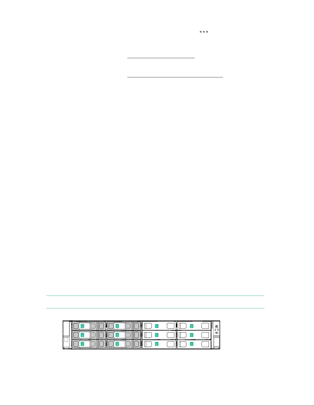
The system comes with six 4 TB disks already installed in the left six disk bays numbered 1, 2, 5, 6, 9,
and 10; the remaining disk bays are filled with blanking plates.
The capacity upgrade kit contains six 4 TB disks that you will install in the right six disk bays numbered 3,
4, 7, 8, 11, and 12.
NOTE: All six disks in the capacity upgrade kit must be installed before you can expand storage.
Figure 2: Disk bays populated before expansion
16 HPE StoreOnce 3620 System
Page 17
Procedure
2
3
1
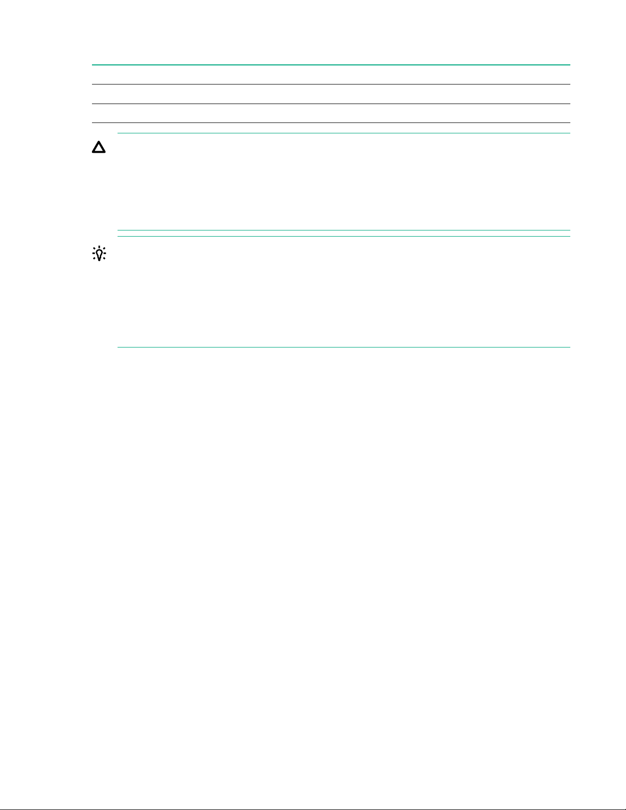
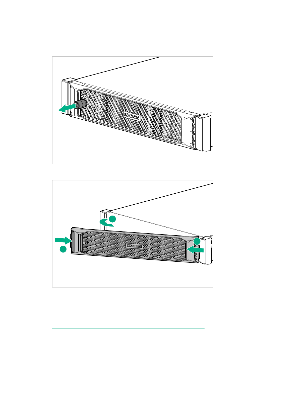
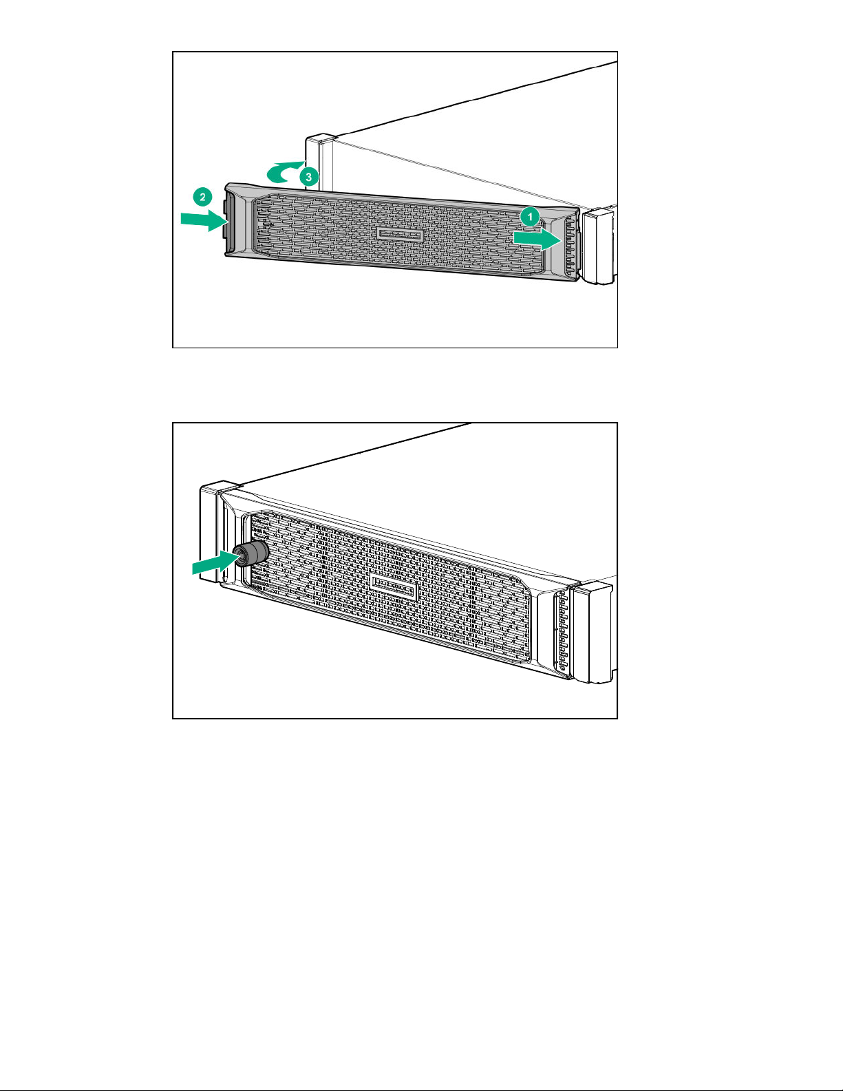
1. Remove the front bezel from the StoreOnce System.
Remove the locking device to unlock the security bezel. Pull the bezel out and away from the front of
the appliance.
Figure 3: Removing the locking device
Figure 4: Removing the front bezel
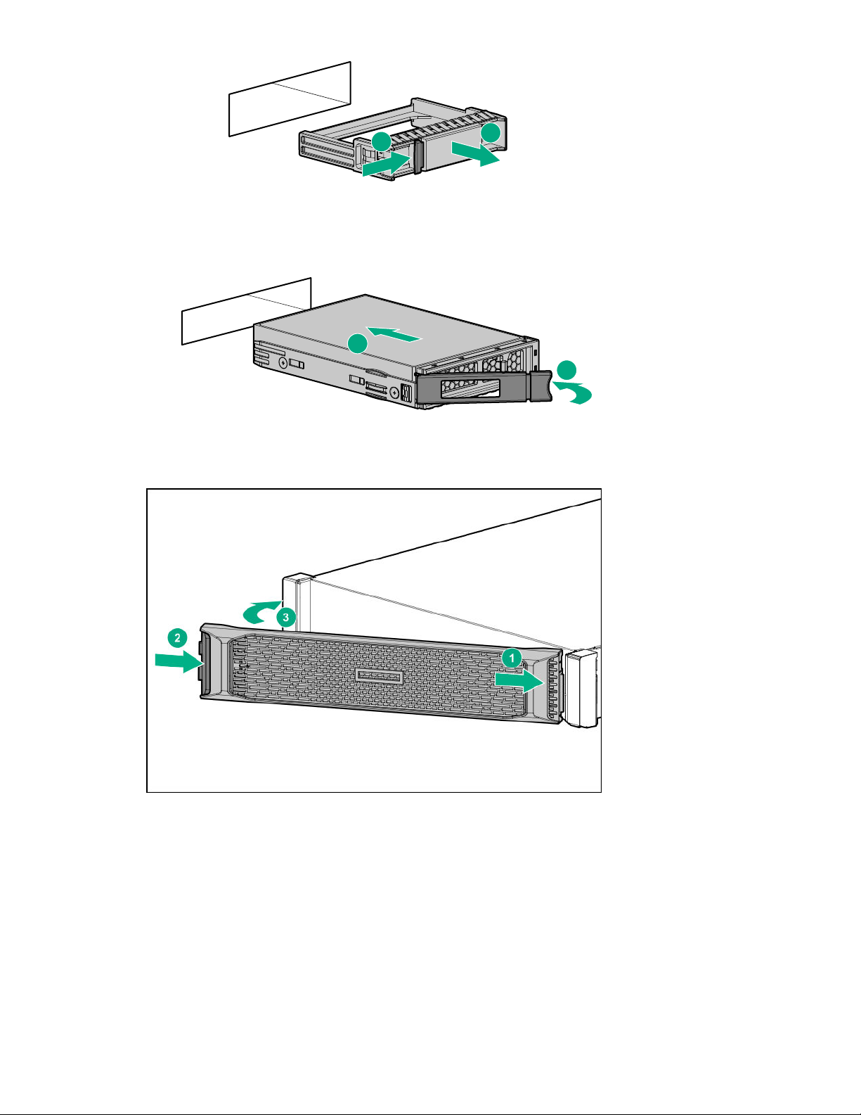
2. Remove the blanking plates from the right six disk bays numbered 3, 4, 7, 8, 11, and 12. Push in the
latch (1) until it releases and pull out the plate (2).
NOTE: All six disks must be installed before you can expand storage.
HPE StoreOnce 3620 System 17
Page 18
1
2
Figure 5: Removing the blanking plates
1
2
3. Push the hard drive assembly into each drive bay (1) until it stops and press the HDD carrier latch (2)
inward until it clicks.
Figure 6: Installing the hard disk
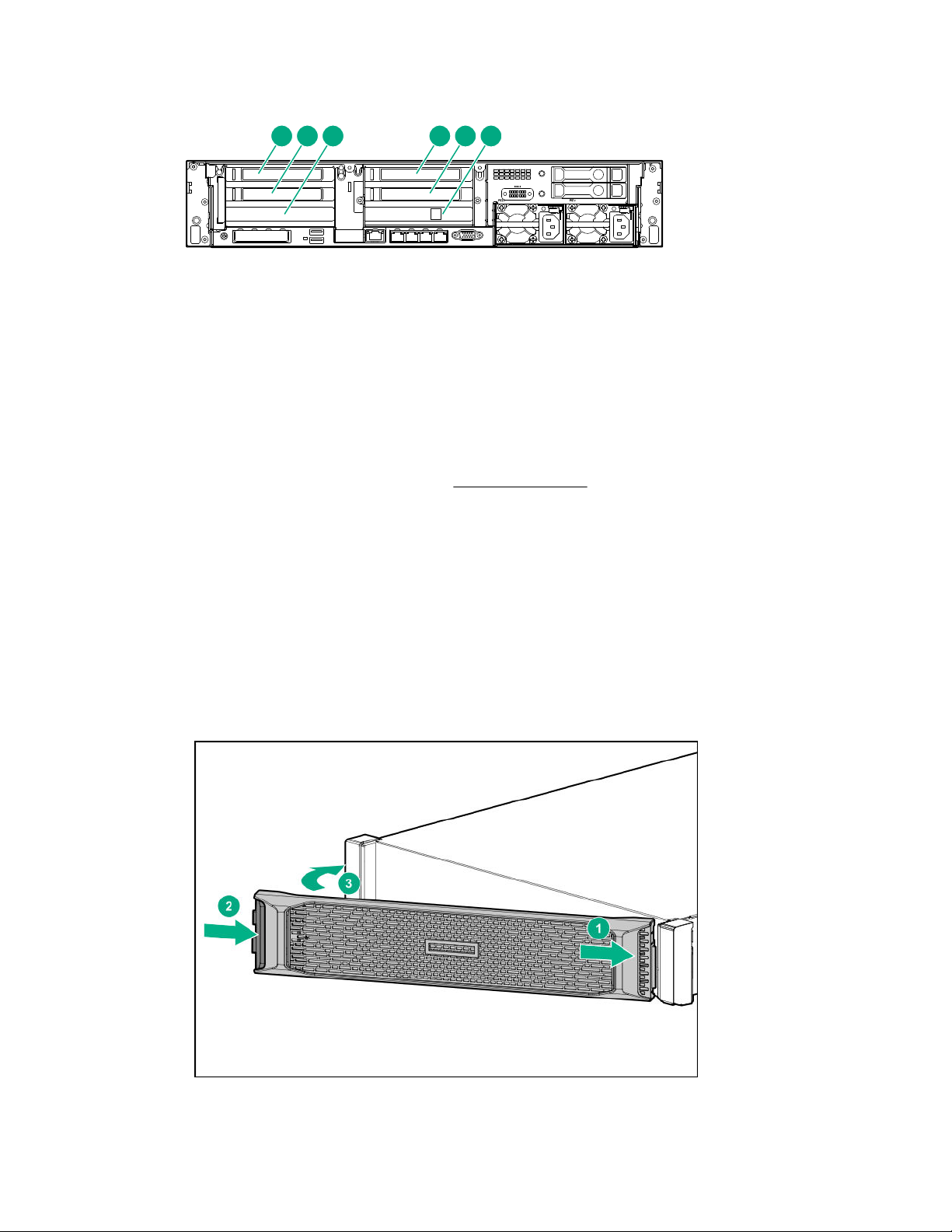
4. Replace the front bezel when all six disks are installed, and install the locking device.
Figure 7: Replacing the front bezel
18 HPE StoreOnce 3620 System
Page 19
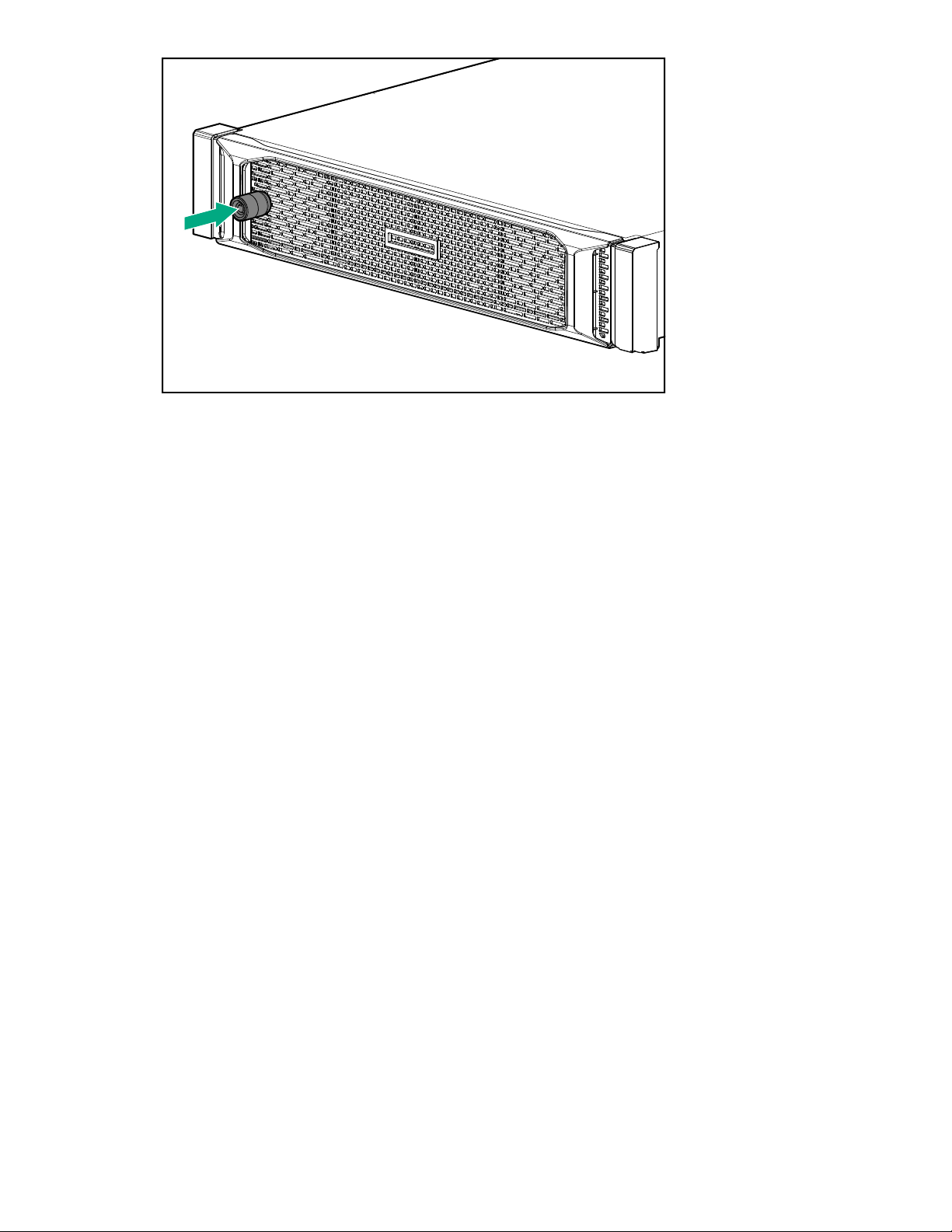
Figure 8: Installing the locking device
HPE StoreOnce 3620 System 19
Page 20

HPE StoreOnce 3640 System
HPE StoreOnce 3640 System
Base system
The HPE StoreOnce 3640 System consists of a server with preconfigured storage on 12 hard disks of 4
TB each.
Capacity upgrade options
BB962A: HPE StoreOnce 3640 48 TB Capacity Upgrade Kit
One 2U storage enclosure containing an IO module and twelve 4 TB disks. You can add a maximum of
two enclosures to the system.
Optional hardware
Four PCIe slots are available for optional hardware.
• BB984A StoreOnce 10GbE-T 2-port Ethernet card
• BB982A StoreOnce 10/25Gb SFP 2-port Ethernet card
• BB986A StoreOnce 16Gb Fibre Channel 2-port card
• BB990A StoreOnce 32 Gb Fibre Channel 2-port card
HPE StoreOnce 3640 System installation process overview
Procedure
1. Prepare the rack.
2. Verify system handling requirements.
3. Install the StoreOnce 3640 System server.
4. Install the capacity upgrade enclosures, if any.
5. Configure the newly installed system.
Preparing the rack for the StoreOnce 3640 System
Procedure
1. Ensure that there is space in the rack for the server and any additional capacity upgrade storage
enclosures.
• The base system requires 2U.
• The system supports up to two capacity upgrade storage enclosures. Each enclosure requires 2U.
• Storage enclosures must be installed under the system server so the cables reach.
20 HPE StoreOnce 3640 System
Page 21
1
2
3
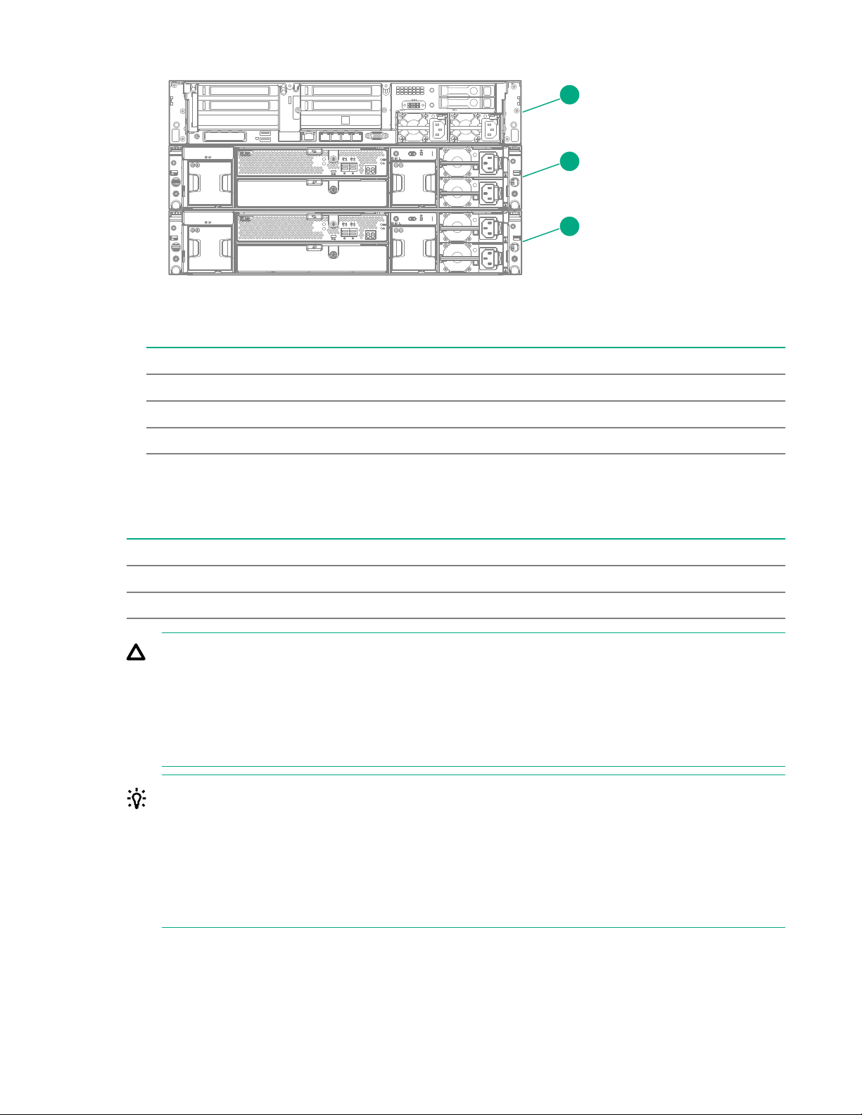
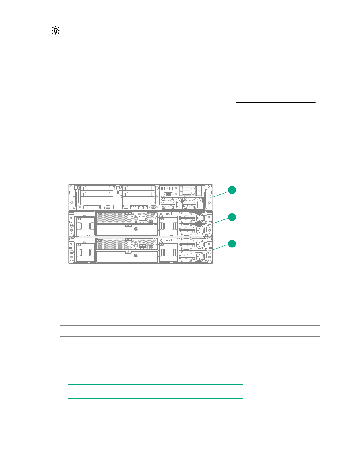
Figure 9: HPE StoreOnce 3640 System rack layout
Item Description
1 Server node.
2 JBOD 1: First capacity upgrade kit. Install under the server.
3 JBOD 2: Second capacity upgrade kit. Install under JBOD 1.
2. Install two power cords for the server and two power cords for each capacity upgrade enclosure.
HPE StoreOnce 3640 System handling requirements
Component Rack space Weight
System server 2U 29 kg (64 lbs)
Capacity upgrade enclosure 2U 26.2 kg (58 lbs)
CAUTION: Use extreme care when installing and pulling units from the rack. Unattached units can
slip and fall, damaging the StoreOnce System or causing personal injury.
• Always use at least two people to lift and locate the server or enclosure into the rack.
• Hewlett Packard Enterprise is not responsible for any damage or injury caused by mishandling
the StoreOnce System.
TIP: Hard disks are preconfigured and must remain installed or returned to the same disk slots they
arrived in.
You can remove the hard disks to make the enclosures lighter and easier to install. All hard disks
must be returned to their original slots before the system is powered on. Failure to return each disk
to its proper location will result in the system failing to start.
Label the disks with the provided label kits before removing them from the enclosure for ease of
installation and maintenance.
HPE StoreOnce 3640 System 21
Page 22

Installing the StoreOnce 3640 System server
1 2 3 4 5 6
Prerequisites
Required tools:
• Torx T25 screwdriver
• A monitor and USB keyboard or a KVM for initial network configuration
Procedure
1. Verify that you received the following components:
• StoreOnce System server
• Rail kit
• Security bezel
• Two power cables
• Two network cables
2. Record the iLO default network information from the label on top of the server.
iLO user name:________________________
iLO network name:_____________________
iLO password:_________________________
3. Install the optional PCIe cards, if necessary.
• If the optional PCIe cards were ordered with the system, they have been preinstalled.
• If the cards were ordered separately, install them now.
Figure 10: PCI slot numbering
a. Install the network cards starting in PCI slot 1 and then additional network cards in slots 2, 4, and
5 in that order.
b. Install the FC cards starting at PCI slot 5 and then additional FC cards in slots 4, 2, and 1 in that
order.
c. Verify that the correct SFP+ transceivers are fitted, if necessary.
22 HPE StoreOnce 3640 System
For detailed installation instructions, see Install PCIe cards .
Page 23
4. Install the StoreOnce server in the rack.
a. Install the rail kit for the StoreOnce server. See the installation instructions supplied with the rail
kit.
b. Insert the two locking nuts for the server into the rack; one on each front column.
c. Install the server into the rack and secure it using the thumbscrews on the front bezel of the
server.
5. Connect the StoreOnce server.
a. Connect the power cables.
Connect each power cable to a separate PDU in the rack.
b. Connect a network cable to LAN port 1.
c. Connect a network cable to the iLO port (recommended).
d. Connect a VGA monitor and a USB keyboard for initial configuration.
6. Attach the security bezel to the front of the server.
a. Insert the security bezel right tab into the slot on the chassis and then rotate the bezel to close.
HPE StoreOnce 3640 System 23
Page 24
b. Lock the bezel.
The key to lock the bezel is attached to the back of the security bezel. One key is supplied.
7. Power on the StoreOnce System (the power button is on the front of the server).
• The power button LED flashes green at the start of the power-on sequence and then turns solid
green.
• The system health LED flashes green at the start of the power-on sequence and then turns solid
green.
• If LAN port 1 is connected to an active link, the NIC status LED will also begin to flash green
when the StoreOnce System is powering up.
• While configuring the system using iLO virtual console, the UID LED flashes blue.
While configuring the system using iLO virtual console, the UID LED flashes blue.
24 HPE StoreOnce 3640 System
Page 25
1
2
3
4
Item Description
1 Power LED and on/off button
2 NIC status LED
3 System health LED
4 UID LED
After successful bootup, the console displays a login prompt.
8. Configure iLO during bootup (recommended).
Most iLO settings must be configured during bootup. The iLO network options can also be configured
with the System Manager.
a. Press F9 System Utilities.
b. Navigate to System Configuration > iLO 5 Configuration > Network Options.
c. Configure the iLO network options and note the details.
iLO IP address:___________________________
iLO subnet mask:_________________________
iLO gateway:_____________________________
9. Configure the basic network.
By default, the system will have already attempted to obtain a DHCP address on LAN port 1. If you
already know the IP address that was assigned over DHCP, this step is optional.
a. Log in using the default user name and password.
Default user name: console
Default password: changeme
b. Change the console password to proceed.
HPE StoreOnce 3640 System 25
Page 26
Choose a secure password with at least eight characters that is memorable to you.
c. If the system obtained an IP address through DHCP, it is displayed. To configure a static address
for LAN port 1 (eno1), select the Configure initial network option from the console menu.
Note the DHCP assigned IP address or the static address details.
IP address:______________________________
Prefix length:_____________________________
Gateway:________________________________
DNS:________________________________
You can remove the console display and keyboard.
10. Open a web browser and use the IP address from the previous step to access the StoreOnce
system. The First Time Setup wizard is automatically displayed. Use the First Time Setup wizard to
configure the system for use.
The setup steps include:
• Setting the Administrator Password.
• Setting the Console Password.
• Setting basic System Information such as the system name (host name), location, and contact
information.
• Setting the System Date & Time. You can set the date and time manually, or synchronize the
date and time with a network time server.
• Configuring Storage. The wizard detects the factory installed storage. The wizard also enables
you to configure additional storage capacity that you might have installed. The wizard also reports
issues with additional storage, for example, when additional storage is not installed in the correct
location.
• Configuring Remote Support.
Installing the capacity upgrade enclosures during the initial system installation
CAUTION: Use extreme caution when installing and pulling units from the rack. Unattached units
can slip and fall, damaging the StoreOnce System or causing personal injury. Hewlett Packard
Enterprise is not responsible for any damage or injury caused by mishandling the StoreOnce
System.
Component Rack space Weight
Capacity upgrade enclosure 2U 26.2 kg (58 lbs)
Always use at least two people to lift and locate an enclosure into the rack.
26 HPE StoreOnce 3640 System
Page 27
TIP: Hard disks are preconfigured and must remain installed or returned to the same disk slots they
1
2
3
arrived in.
You can remove the hard disks to make the enclosures lighter and easier to install. All hard disks
must be returned to their original slots before the system is powered on. Failure to return each disk
to its proper location will result in the system failing to start.
Label the disks with the provided label kits before removing them from the enclosure for ease of
installation and maintenance.
Skip this step if the system does not have a capacity upgrade enclosure.
If you are adding a capacity upgrade enclosure to a running system, see Installing and connecting the
capacity upgrade enclosures.
Procedure
1. Power off the StoreOnce server.
2. Verify the rack locations for the capacity upgrade enclosures.
If the system has two capacity upgrade enclosures, install the rails for both enclosures and then install
the lowest storage enclosure first.
Figure 11: StoreOnce 3640 System rack layout
Item Description
1 Server node.
2 JBOD 1: First capacity upgrade kit. Install below the server.
3 JBOD 2: Second capacity upgrade kit. Install below JBOD 1.
3. Install the enclosure rails in the rack.
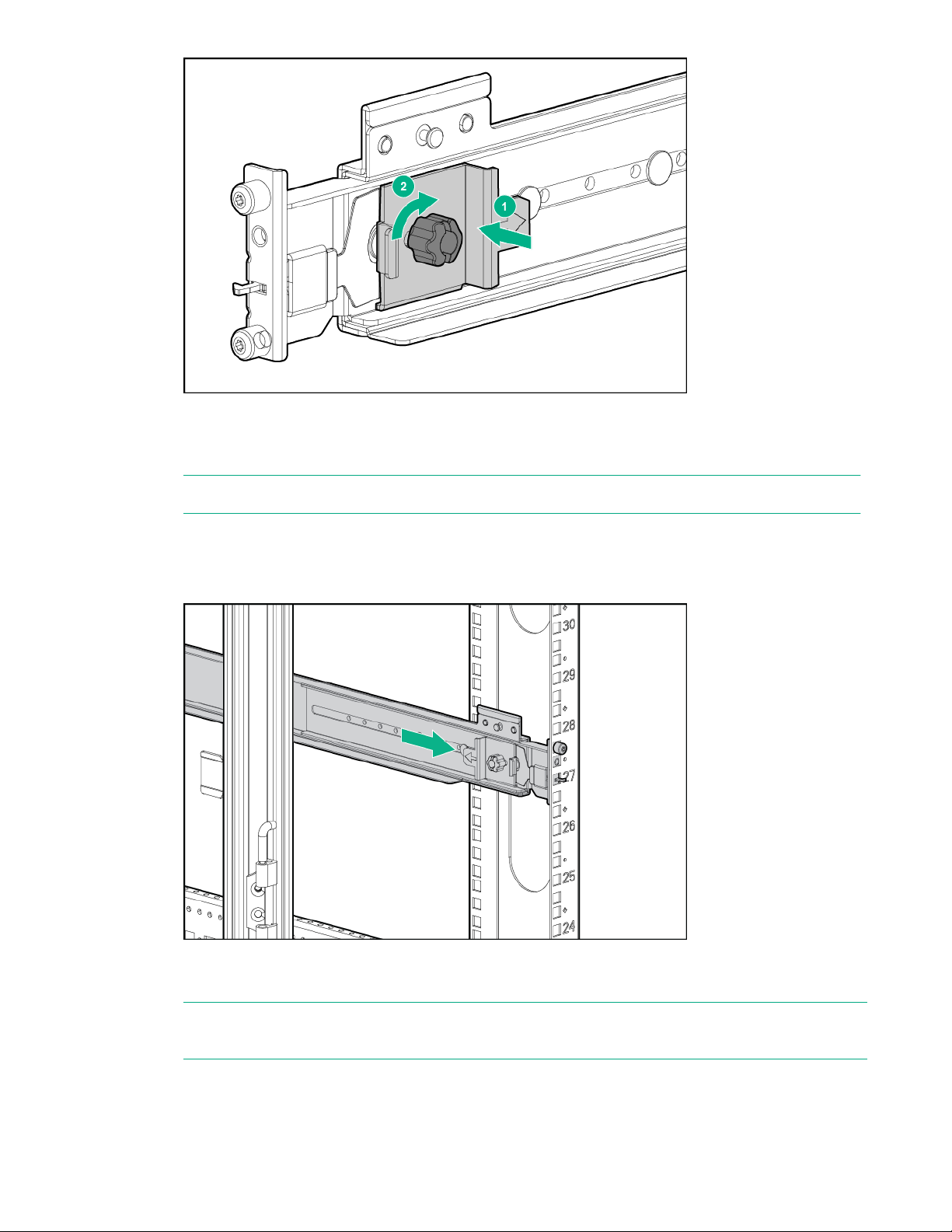
a. Adjust the back bracket on the standard rail kit so it accommodates the storage enclosure. Attach
rear hold down brackets by sliding the tab with the arrow pointed forward (1) into the corresponding
slot on the left and right side of the rear of the chassis. Use the black headed thumb screw to
secure tightly to the rail in the second hole from the rear (2).
NOTE: It is easier to make this adjustment prior to mounting the rails.
HPE StoreOnce 3640 System 27
Page 28
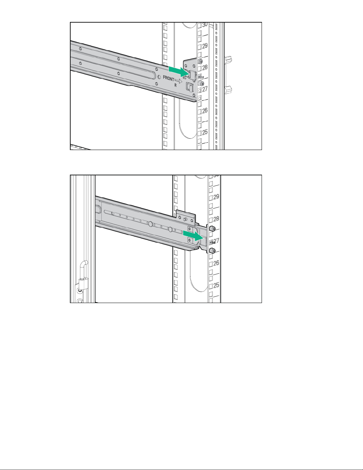
b. Position left and right rack rails at the necessary 'U' position in the rack, adjusting the rails to fit the
rack, as needed. Front and Rear bottom edge of rails must align with the bottom of EIA boundary in
the lowermost 'U'.
NOTE: Rails are marked L and R with an arrow indicating the direction in which the rail is installed.
c. Use guide pins to align the shelf mount kit to the rack column holes.
d. To engage the rear rack rail mount, push the rail toward the back of the rack until the spring hook
snaps into place.
e. To engage the front rack rail mount, pull the rail towards the front of the rack to engage the spring
hook with the rack column in the same manner as the rear spring hook.
NOTE: Make sure that the respective guide pins for the square or round hole rack align properly
into rack column hole spacing.
28 HPE StoreOnce 3640 System
Page 29
f. Secure the rear of the rack rail to the rack column with the round- or square-hole shoulder screws
provided in the package.
g. Secure front of the rack rail to the front rack column using the provided flat securing screw in the
bottom screw position of the rail.
HPE StoreOnce 3640 System 29
Page 30
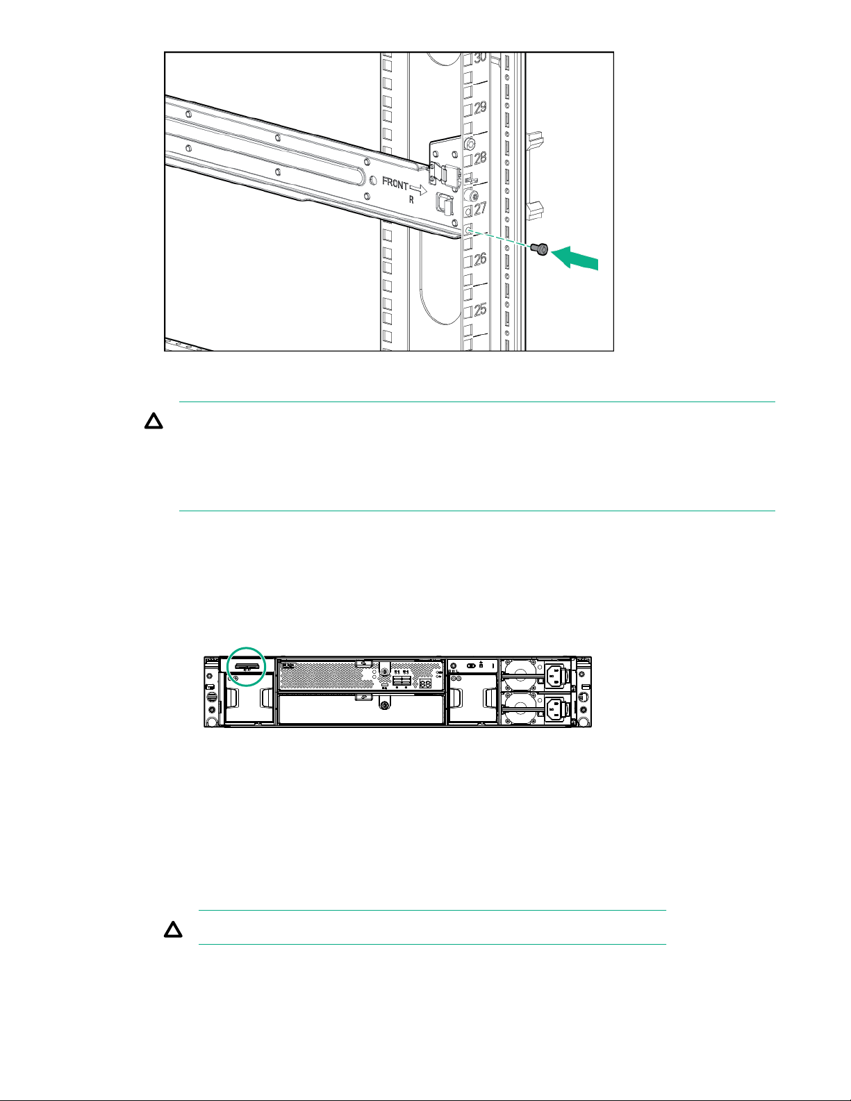
4. Install the enclosure into the rack.
CAUTION: Use extreme caution when installing and pulling units from the rack. Unattached units
can slip and fall, damaging the StoreOnce System or causing personal injury. Hewlett Packard
Enterprise is not responsible for any damage or injury caused by mishandling the StoreOnce
system.
Always use at least two people to lift and locate an enclosure into the rack.
a. Verify that the storage enclosure has the correct JBOD number.
The storage enclosure has a pull-out tab in the upper left corner of the rear panel. The tab shows
the JBOD number. In a system with multiple enclosures, having the correct JBOD numbers on each
pull-out tab will ease any necessary troubleshooting procedures.
• If the enclosure was part of the initial order, the JBOD number is preinstalled on the pull-out tab.
• If the enclosure was not part of the initial order, apply the JBOD number from the sheet of
stickers to the pull-out tab.
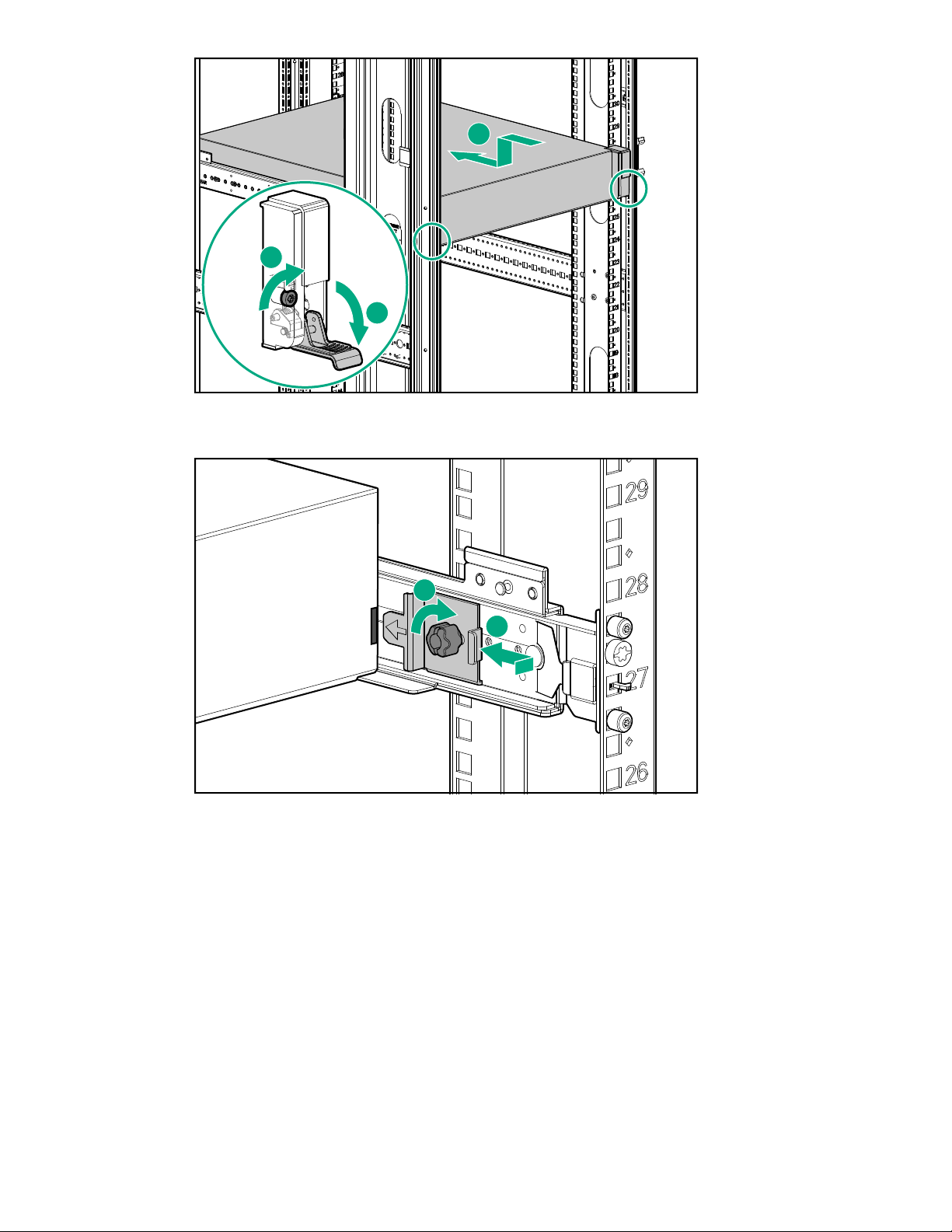
b. Slide the enclosures into position on the rails (1). Secure the chassis into the rack by tightening the
captive CTO screw behind the latch on the front left and right bezel ears of the chassis (2).
CAUTION: The front CTO screw must be attached at all times when racked.
When installing two storage enclosures, slide the lowest enclosure, JBOD 2, into position first.
30 HPE StoreOnce 3640 System
Page 31

1
2
3
c. Attach the rear hold down brackets by sliding the tab with the arrow pointed forward into the
1
2
corresponding slot on the left and right side of the rear of the chassis.
5. Use the black headed thumb screw to secure the front of the enclosure tightly to the rail.
6. Connect the storage enclosure cables.
The supplied cables are labeled on both ends with the following convention.
• N = Node (server node)
• S = Slot
• P = Port
• J = JBOD
• I = I/O module
HPE StoreOnce 3640 System 31
Page 32

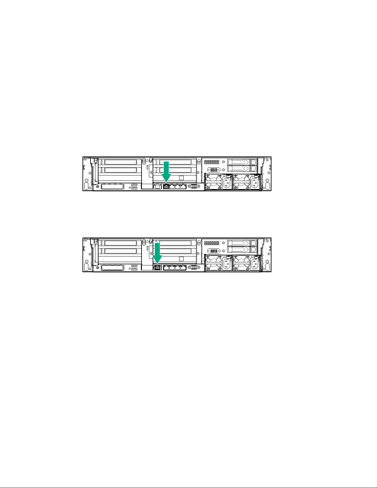
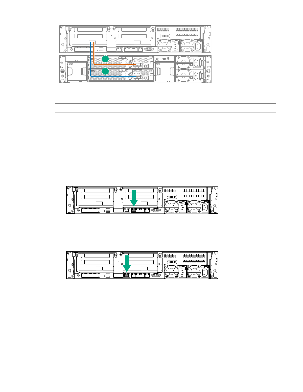
a. Connect a 0.5 m SAS cable from the RAID controller on the server node to port 1 on the capacity
1
2
3
1
2
3
4
upgrade enclosure (JBOD 1).
If the cable is not already labeled, apply the labels before installing the cable.
SAS cable Label color Label
New 0.5 m cable Red N:S6:P1 - J1:I1:P1
Item Description
1 Server node.
2 JBOD 1: First capacity upgrade kit.
3 0.5 m SAS cable.
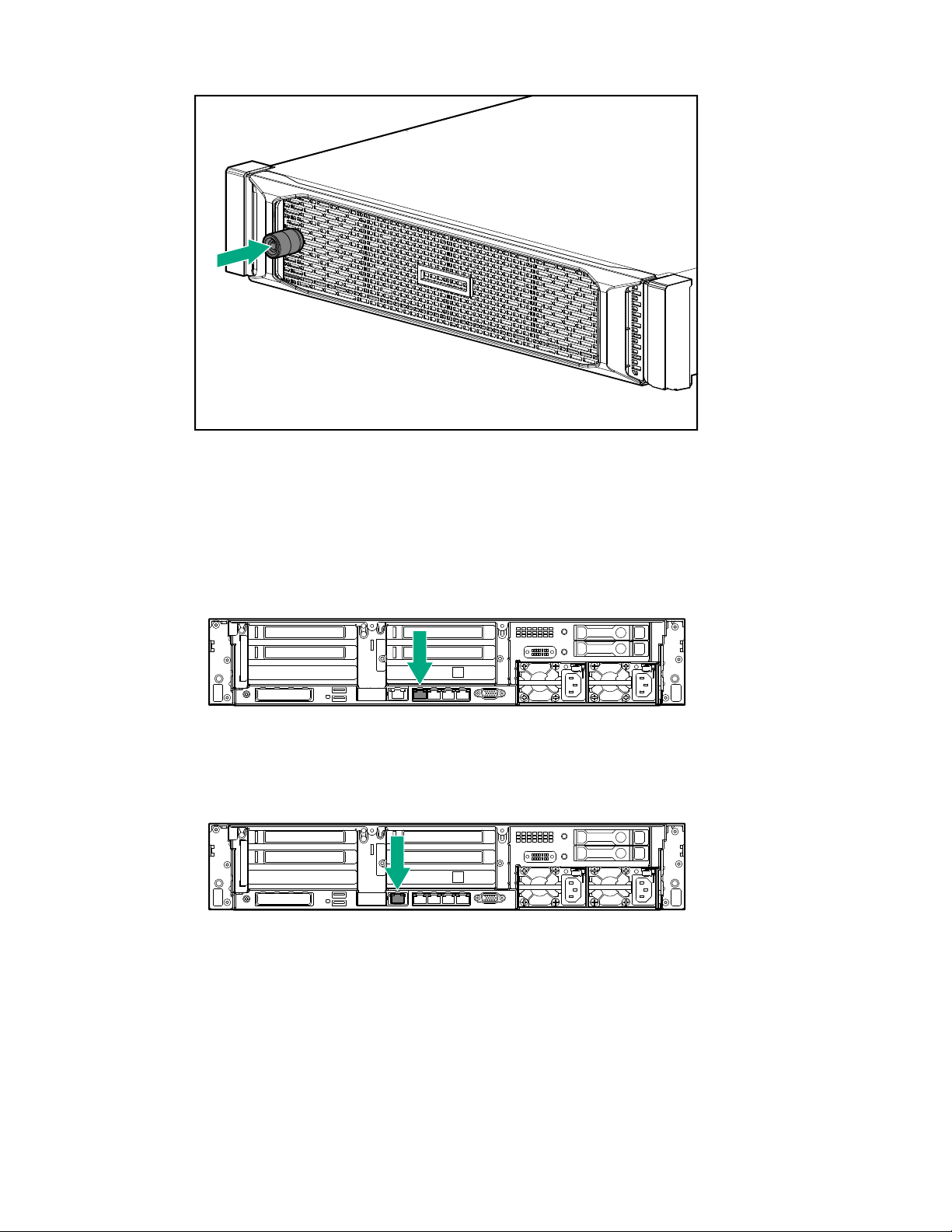
b. If the system includes a second capacity upgrade enclosure, connect a 0.5 m SAS cable from port
2 on the first capacity upgrade enclosure (JBOD 1) to port 1 on the second capacity upgrade
enclosure (JBOD 2).
If the cable is not already labeled, apply the labels before installing the cable.
SAS cable Label color Label
New 0.5 m SAS cable Red J1:I1:P2 - J2:I1:P1
Figure 12: Cabling the second capacity upgrade enclosure
32 HPE StoreOnce 3640 System
Page 33

Item Description
1 Server node.
2 JBOD 1: First capacity upgrade kit.
3 JBOD 2: Second capacity upgrade kit.
4 0.5 m cable.
c. Connect two power cables to each enclosure. Connect each power cable to a different PDU.
7. Power on the StoreOnce System.
Configuring a newly installed StoreOnce 3640 system
For additional information and instructions on each step, see the online help or user guide.
Procedure
1. Log on to the StoreOnce Management Console. Review and update the settings that were
configured with the First Time Setup Wizard.
• Administrator password
• System information, such as system, location, and contact information
• System date and time, or NTP configuration
• Storage configuration
• Remote Support configuration
• Console password
2. Complete the network configuration.
On the main menu, select Settings. In the Hardware section, click the Networking panel.
For additional information, see Initial StoreOnce network configuration.
3. Redeem licenses, if necessary. Capacity or feature licenses ordered with the system will be
preinstalled. If ordered separately, redeem them now.
The capacity upgrade kit includes a license entitlement certificate. The certificate is a paper
document containing the information necessary to obtain your unique LTU (License to Use) key file
from the HPE Licensing website.
NOTE: Redeem licenses individually to obtain a license key file for each upgrade kit. Do not merge
multiple entitlements to redeem a single license key file.
IMPORTANT: You must add the licenses before expanding the capacity of the StoreOnce
System. The storage expansion process will not configure unlicensed storage attached to the
system.
a. On the main menu, select Settings.. From the System panel, select the License Management.
b. On the Overview tab, make a note of the Locking ID (Serial Number).
HPE StoreOnce 3640 System 33
Page 34

If you are managing the system through the federation lead, ensure that you are viewing the
correct system.
c. Go to the HPE Licensing website, as directed in the License Entitlement Certificate.
d. Log in using your HPE Passport user ID and password.
e. Enter your Entitlement Order Number to search for your license.
f. Follow the steps to activate and obtain your license.
You can obtain the license file by downloading it directly from the website or from an email with
a .zip attachment.
g. Return to the License Management screen in the StoreOnce Management Console.
h. Expand the Actions menu ( ), click the Add License icon ( ), and then follow the onscreen
instructions.
4. Configure licenses, if necessary. Capacity or feature licenses ordered with the system will be
preinstalled. If ordered separately, configure them now.
a. On the main menu, select Settings.
b. In the Systems section, click the License Management panel.
• To view a license summary, click the Overview tab.
• To view a list of the installed licenses, click the Licenses tab.
For additional information, see Licensing.
5. Configure user accounts.
a. On the main menu, select Settings.
b. In the User Management section, click the Users and Groups panel panel.
• To add a user or group, select Add user or group on the Actions menu.
• To edit a user, click the user name.
• To remove a user, click the user name and then click Remove.
For additional information, see User roles and types.
6. Configure StoreOnce email alerts.
To display the configured email alerts, select Notifications from the Settings menu item.
7. Configure SNMP.
a. On the main menu, select Settings.
b. In the Notifications section, click the SNMP panel.
34 HPE StoreOnce 3640 System
Page 35

• To view summaries of the SNMP configuration, click the Overview tab. To view lists of the
items in the summaries, click the graphic segments and legends.
• To configure SNMP, select the tabs for Agent Setup, Trapsinks, and Users.
8. Apply an SSL certificate.
a. On the main menu, select Settings.
b. In the Security section, click the Certificates panel.
c. On the Certificates screen, select Generate CSR on the Actions menu.
9. Expand storage, if necessary. Capacity upgrades ordered with the system will have already been
configured. If capacity upgrades were ordered separately, configure them now.
a. On the main menu, select Settings.
b. In the Hardware section, click the Storage panel.
c. On the Storage screen, click the Local Storage tab, and then expand the Actions ( ) menu
and select Rescan.
Newly detected storage is added to the storage list with a status of Unconfigured.
d. To configure the new storage for use, expand the Actions ( ) menu and select Configure.
10. Configure Remote Support using STaTS.
For additional information, see StoreOnce Remote Support.
11. Configure Fibre Channel.
For additional information, see Fibre Channel with StoreOnce Systems.
12. Configure iLO, if necessary.
If you plan to use iLO with the system and did not configure it during the system installation,
configure iLO now.
• View or update the iLO configuration from the StoreOnce Management Console.
a. On the main menu, select Settings.
b. In the Hardware section, click the Integrated Lights Out (iLO) Configuration panel.
The Integrated Lights Out (iLO) Configuration screen shows the HPE Integrated Lights Out
network configuration.
• In environments that do not use DHCP, DNS, or WINS, configure a static IP address during
bootup.
a. Restart or power on the StoreOnce Server.
b. Press F9 in the server POST screen.
The UEFI System Utilities start.
HPE StoreOnce 3640 System 35
Page 36

c. Navigate to System Configuration > iLO 5 Configuration > Network Options.
d. Configure the iLO network options and note the iLO IP address, iLO subnet mask, and iLO
gateway.
13. The StoreOnce 3640 System is now installed and ready for production use.
36 HPE StoreOnce 3640 System
Page 37

HPE StoreOnce 5200 System
HPE StoreOnce 5200 System
Base system components
• A server (containing operating system disks only)
• One 2U storage enclosure with two IO modules and twelve 4 TB preconfigured disks.
Capacity upgrade options
BB964A: HPE StoreOnce 5200 48 TB Capacity Upgrade Kit
One 2U storage enclosure containing two IO modules and twelve 4 TB preconfigured disks. You can add
up to five enclosures to the base system for a maximum configuration of six enclosures on the system.
Optional hardware
Four PCIe slots are available optional hardware.
• BB984A: StoreOnce 10GbE-T 2-port Ethernet card
• BB982A: StoreOnce 10/25Gb SFP 2-port Ethernet card
• BB986A: StoreOnce 16Gb Fibre Channel 2-port card
• BB990A: StoreOnce 32 Gb Fibre Channel 2-port card
HPE StoreOnce 5200 System installation process overview
Procedure
1. Prepare the rack.
2. Verify system handling requirements.
3. Install the StoreOnce 5200 base system.
4. Install the capacity upgrade enclosures, if any.
Capacity upgrade enclosures can be installed before or after configuring the newly installed system.
5. Configure the newly installed system.
Preparing the rack for the StoreOnce 5200 System
Procedure
1. Ensure that there is space in the rack for the server, base storage enclosure, and any additional
capacity upgrade storage enclosures.
HPE StoreOnce 5200 System 37
Page 38

• The base system requires 4U. The server and base storage enclosure each require 2U.
1
2
3
4
5
6
7
• The system supports up to five capacity upgrade storage enclosures. Each enclosure requires 2U.
• The storage enclosures must be installed in the locations shown.
Figure 13: HPE StoreOnce 5200 System rack layout
Item Description
1 JBOD 6: Fifth capacity upgrade kit. Install above JBOD 4.
2 JBOD 4: Third capacity upgrade kit. Install above JBOD 2.
3 JBOD 2: First capacity upgrade kit. Install above the server.
4 Server node.
5 JBOD 1: Base enclosure. Install under the server.
6 JBOD 3: Second capacity upgrade kit. Install under JBOD 1.
7 JBOD 5: Fourth capacity upgrade kit. Install under JBOD 3.
2. Install two power cords for the server and each storage enclosure.
HPE StoreOnce 5200 System handling requirements
Component Rack space Weight
System server 2U 29 kg (64 lbs)
Storage enclosures 2U 27.2 kg (60 lbs)
38 HPE StoreOnce 5200 System
Page 39

CAUTION: Use extreme care when installing and pulling units from the rack. Unattached units can
slip and fall, damaging the StoreOnce System or causing personal injury.
• Always use at least two people to lift and locate the server or enclosure into the rack.
• Hewlett Packard Enterprise is not responsible for any damage or injury caused by mishandling
the StoreOnce System.
TIP: Hard disks are preconfigured and must remain installed or returned to the same disk slots they
arrived in.
You can remove the hard disks to make the enclosures lighter and easier to install. All hard disks
must be returned to their original slots before the system is powered on. Failure to return each disk
to its proper location will result in the system failing to start.
Label the disks with the provided label kits before removing them from the enclosure for ease of
installation and maintenance.
Installing the StoreOnce 5200 System
Prerequisites
Required tools:
• Torx T25 screwdriver
• A monitor and USB keyboard or a KVM for initial network configuration
Procedure
1. Verify that you received the server components.
• StoreOnce System server
• Rail kit
• Security bezel
• Two power cables
• Two network cables
2. Verify that you received the base storage enclosure contents.
• 2U storage enclosure with 12 disks
• Rail kit
• Two power cables
• SAS cables
◦ One 1 m cable
◦ One 2 m cable
3. Record the iLO default network information from the label on top of the server.
HPE StoreOnce 5200 System 39
Page 40

iLO user name:________________________
1 2 3 4 5 6
iLO network name:_____________________
iLO password:_________________________
4. Install the optional PCIe cards, if necessary.
If the optional PCIe cards were ordered with the system, they have been preinstalled. If the cards
were ordered separately, install them now.
Figure 14: PCI slot numbers
a. Install the network cards starting in PCI slot 1 and then additional network cards in slots 2, 4, and
5 in that order.
b. Install the FC cards starting at PCI slot 5 and then additional FC cards in slots 4, 2, and 1 in that
order.
c. Verify that the correct SFP+ transceivers are fitted, if necessary.
For detailed installation instructions, see Install PCIe cards .
5. Install the server in the rack.
a. Install the rail kit for the StoreOnce server. See the installation instructions that ship with the rail
kit.
b. Insert the two locking nuts for the server into the rack; one on each front column.
c. Install the server into the rack and secure it using the thumbscrews on the front bezel of the
server.
6. Install the rails for the base storage enclosure in the rack, directly under the server.
a. Adjust the back bracket on the standard rail kit to accommodate the storage enclosure. Attach
rear hold down brackets by sliding the tab with the arrow pointed forward (1) into the
corresponding slot on the left and right side of the rear of the chassis. Use the black headed
thumb screw to secure tightly to the rail in the second hole from the rear (2).
NOTE: It is easier to make this adjustment prior to mounting the rails.
40 HPE StoreOnce 5200 System
Page 41

b. Position left and right rack rails at the correct 'U' position in the rack, adjusting the rails to fit the
rack, as needed. Front and Rear bottom edge of rails must align with the bottom of EIA boundary
in the lowermost 'U'.
NOTE: Rails are marked L and R with an arrow indicating the direction in which the rail is
installed.
c. Use guide pins to align the shelf mount kit to the rack column holes.
d. To engage the rear rail rack mount, push the rail toward the back of the rack until the spring hook
snaps into place.
e. To engage the front rail rack mount, pull the rail towards the front of the rack to engage the spring
hook with the rack column in the same manner as the rear spring hook.
NOTE: Make sure that the respective guide pins for the square or round hole rack align properly
into the column hole spacing.
HPE StoreOnce 5200 System 41
Page 42

f. Secure rear of rack rail to the rail column with either the round- or square-hole shoulder screws
provided in the package.
g. Secure front of the rack rail to the front rail column using the provided flat securing screw in the
bottom screw position of the rail.
42 HPE StoreOnce 5200 System
Page 43

7. Fit the storage enclosure into the rack.
CAUTION: Use extreme caution when installing and pulling units from the rack. Unattached
units can slip and fall, damaging the StoreOnce System or causing personal injury. Hewlett
Packard Enterprise is not responsible for any damage or injury caused by mishandling the
StoreOnce System.
Always use at least two people to lift and locate an enclosure into the rack.
a. Check the JBOD pull-out tab in the upper left corner of the rear panel of the storage enclosure.
The base enclosure is labeled "JBOD1". If the system has multiple storage enclosures, verify that
you are installing the base enclosure.
b. Slide the base enclosure into position on the rails (1). Secure the chassis into the rack by
tightening the captive CTO screw behind the latch on the front left and right bezel ears of the
chassis (2).
CAUTION: The front CTO screw must be attached at all times when racked.
HPE StoreOnce 5200 System 43
Page 44
1
2
3
c. Attach the rear hold down brackets by sliding the tab with the arrow pointed forward into the
1
2
corresponding slot on the left and right side of the rear of the chassis.
8. Use the black headed thumb screw to secure the front of the enclosure to the rail tightly.
9. Use the supplied SAS cables to connect the first node server RAID controller card (slot 3) in the
server node to the base storage enclosure.
The supplied cables are labeled on both ends with the following convention.
• N = Node (server node)
• S = Slot
• P = Port
• J = JBOD
• I = I/O module
44 HPE StoreOnce 5200 System
Page 45
1
2
Item SAS cable Label color Cable from To
1 1 m Red Node Slot 3 Port 1 JBOD 1 IOM 1 Port 1
2 2 m Green Node Slot 3 Port 2 JBOD 1 IOM 2 Port 1
10. Connect two power cables to each enclosure. Connect each power cable to a different PDU.
11. Connect the server.
a. Connect the power cables.
Connect each power cable to a separate PDU in the rack.
b. Connect a network cable to LAN port 1.
c. Connect a network cable to the iLO port (recommended).
d. Connect a VGA monitor and a USB keyboard for initial configuration.
12. Attach the security bezel to the front of the server.
a. Insert the security bezel right tab into the slot on the chassis and then rotate the bezel to close.
HPE StoreOnce 5200 System 45
Page 46

b. Lock the bezel.
The key to lock the bezel is attached to the back of the security bezel. One key is supplied.
13. Power on the StoreOnce System (the power button is on the front of the server).
• The power button LED flashes green at the start of the power-on sequence and then turns solid
green.
• The system health LED flashes green at the start of the power-on sequence and then turns solid
green.
• If LAN port 1 is connected to an active link, the NIC status LED will also begin to flash green
when the StoreOnce System is powering up.
• While configuring the system using iLO virtual console, the UID LED flashes blue.
46 HPE StoreOnce 5200 System
Page 47

1
2
3
4
Item Description
1 Power LED and on/off button
2 System health LED
3 NIC status LED
4 UID LED
After successful bootup, the console displays a login prompt.
14. Configure iLO during bootup (recommended).
Most iLO settings must be configured during bootup. The iLO network options can also be configured
with the System Manager.
a. Press F9 System Utilities.
b. Navigate to System Configuration > iLO 5 Configuration > Network Options.
c. Configure the iLO network options and note the details.
iLO IP address:___________________________
iLO subnet mask:_________________________
iLO gateway:_____________________________
15. Configure the basic network.
By default, the system will have already attempted to obtain a DHCP address on LAN port 1. If you
already know the IP address that was assigned over DHCP, this step is optional.
a. Log in using the default user name and password.
Default user name: console
Default password: changeme
b. Change the console password to proceed.
HPE StoreOnce 5200 System 47
Page 48

Choose a secure password with at least eight characters that is memorable to you.
c. To configure a static address for LAN port 1 (eno1), select the Configure initial network
option from the console menu.
Note the DHCP assigned IP address or the static address details.
IP address:______________________________
Prefix length:_____________________________
Gateway:________________________________
DNS:________________________________
You can remove the console display and keyboard.
16. Open a web browser and use the IP address from the previous step to access the StoreOnce
system. The First Time Setup wizard is automatically displayed. Use the First Time Setup wizard to
configure the system for use.
The setup steps include:
• Setting the Administrator Password.
• Setting the Console Password.
• Setting basic System Information such as the system name (host name), location, and contact
information.
• Setting the System Date & Time. You can set the date and time manually, or synchronize the
date and time with a network time server.
• Configuring Storage. The wizard detects the factory installed storage. The wizard also enables
you to configure additional storage capacity that you might have installed. The wizard also reports
issues with additional storage, for example, when additional storage is not installed in the correct
location.
• Configuring Remote Support.
Configuring a newly installed StoreOnce 5200 system
If the system has capacity upgrade enclosures, you can install and configure them before or after
configuring the newly installed system. To install the capacity upgrade kits now, see Installing and
connecting the capacity upgrade enclosures.
For additional information and instructions on each step, see the online help or user guide.
Procedure
1. Log on to the StoreOnce Management Console. Review and update the settings that were
configured with the First Time Setup Wizard.
• Administrator password
• System information, such as system, location, and contact information
• System date and time, or NTP configuration
• Storage configuration
48 HPE StoreOnce 5200 System
Page 49

• Remote Support configuration
• Console password
2. Complete the network configuration.
On the main menu, select Settings. In the Hardware section, click the Networking panel.
For additional information, see Initial StoreOnce network configuration.
3. Redeem licenses, if necessary. Capacity or feature licenses ordered with the system will be
preinstalled. If ordered separately, redeem them now.
The capacity upgrade kit includes a license entitlement certificate. The certificate is a paper
document containing the information necessary to obtain your unique LTU (License to Use) key file
from the HPE Licensing website.
NOTE: Redeem licenses individually to obtain a license key file for each upgrade kit. Do not merge
multiple entitlements to redeem a single license key file.
IMPORTANT: You must add the licenses before expanding the capacity of the StoreOnce
System. The storage expansion process will not configure unlicensed storage attached to the
system.
a. On the main menu, select Settings.. From the System panel, select the License Management.
b. On the Overview tab, make a note of the Locking ID (Serial Number).
If you are managing the system through the federation lead, ensure that you are viewing the
correct system.
c. Go to the HPE Licensing website, as directed in the License Entitlement Certificate.
d. Log in using your HPE Passport user ID and password.
e. Enter your Entitlement Order Number to search for your license.
f. Follow the steps to activate and obtain your license.
You can obtain the license file by downloading it directly from the website or from an email with
a .zip attachment.
g. Return to the License Management screen in the StoreOnce Management Console.
h. Expand the Actions menu ( ), click the Add License icon ( ), and then follow the onscreen
instructions.
4. Configure licenses, if necessary. Capacity or feature licenses ordered with the system will be
preinstalled. If ordered separately, configure them now.
a. On the main menu, select Settings.
b. In the Systems section, click the License Management panel.
• To view a license summary, click the Overview tab.
• To view a list of the installed licenses, click the Licenses tab.
For additional information, see Licensing.
HPE StoreOnce 5200 System 49
Page 50

5. Configure user accounts.
a. On the main menu, select Settings.
b. In the User Management section, click the Users and Groups panel panel.
• To add a user or group, select Add user or group on the Actions menu.
• To edit a user, click the user name.
• To remove a user, click the user name and then click Remove.
For additional information, see User roles and types.
6. Configure StoreOnce email alerts.
To display the configured email alerts, select Notifications from the Settings menu item.
7. Configure SNMP.
a. On the main menu, select Settings.
b. In the Notifications section, click the SNMP panel.
• To view summaries of the SNMP configuration, click the Overview tab. To view lists of the
items in the summaries, click the graphic segments and legends.
• To configure SNMP, select the tabs for Agent Setup, Trapsinks, and Users.
8. Apply an SSL certificate.
a. On the main menu, select Settings.
b. In the Security section, click the Certificates panel.
c. On the Certificates screen, select Generate CSR on the Actions menu.
9. Expand storage, if necessary. Capacity upgrades ordered with the system will have already been
configured. If capacity upgrades were ordered separately, configure them now.
a. On the main menu, select Settings.
b. In the Hardware section, click the Storage panel.
c. On the Storage screen, click the Local Storage tab, and then expand the Actions ( ) menu
and select Rescan.
Newly detected storage is added to the storage list with a status of Unconfigured.
d. To configure the new storage for use, expand the Actions ( ) menu and select Configure.
10. Configure Remote Support using STaTS.
For additional information, see StoreOnce Remote Support.
11. Configure Fibre Channel.
For additional information, see Fibre Channel with StoreOnce Systems.
12. Configure iLO, if necessary.
50 HPE StoreOnce 5200 System
Page 51

If you plan to use iLO with the system and did not configure it during the system installation,
configure iLO now.
• View or update the iLO configuration from the StoreOnce Management Console.
a. On the main menu, select Settings.
b. In the Hardware section, click the Integrated Lights Out (iLO) Configuration panel.
The Integrated Lights Out (iLO) Configuration screen shows the HPE Integrated Lights Out
network configuration.
• In environments that do not use DHCP, DNS, or WINS, configure a static IP address during
bootup.
a. Restart or power on the StoreOnce Server.
b. Press F9 in the server POST screen.
The UEFI System Utilities start.
c. Navigate to System Configuration > iLO 5 Configuration > Network Options.
d. Configure the iLO network options and note the iLO IP address, iLO subnet mask, and iLO
gateway.
13. The StoreOnce 5200 System is now installed and ready for production use.
HPE StoreOnce 5200 System 51
Page 52

HPE StoreOnce 5250 and 5650 Systems
HPE StoreOnce 5250 and 5650 Systems
Base system components
• A server (containing operating system disks only)
• One 5U storage enclosure with preconfigured storage on fifteen 4 TB or 8 TB hard disks
Capacity upgrade options
• BB974A: HPE StoreOnce 5250/5650 44 TB Capacity Upgrade Kit
One disk pack containing eleven 4 TB preconfigured disks. Add the disk packs to BB966A base and
upgrade enclosures as described in this guide. You can add up to five 44 TB disk packs to a BB966A
enclosure for a total of 70 disks in each enclosure.
• BB966A: HPE StoreOnce 5250/5650 60 TB Drawer Upgrade Kit
One storage enclosure containing fifteen 4 TB preconfigured disks. Once all the bays in the base
enclosure are filled with disk packs, you can add enclosures to your system. Use BB974A disk packs
to completely fill an enclosure before adding another enclosure.
◦ The StoreOnce 5250 System supports a maximum of one upgrade storage enclosure in addition to
the base storage enclosure.
◦ The StoreOnce 5650 System supports a maximum of three upgrade storage enclosures in addition
to the base storage enclosure.
• BB976A: HPE StoreOnce 5250/5650 88 TB Capacity Upgrade Kit
One disk pack containing eleven 8 TB preconfigured disks. Add the disk packs to BB968A base and
upgrade enclosures as described in this guide. You can add up to five 88 TB disk packs to a BB968A
enclosure for a total of 70 disks in each enclosure.
• BB968A: HPE StoreOnce 5250/5650 120 TB Drawer Upgrade Kit
One storage enclosure containing fifteen 8 TB preconfigured disks. Once all the bays in the base
enclosure are filled with disk packs, you can add enclosures to your system. Use BB976A disk packs
to completely fill an enclosure before adding another enclosure.
◦ The StoreOnce 5250 System supports a maximum of one upgrade storage enclosure in addition to
the base storage enclosure.
◦ The StoreOnce 5650 System supports a maximum of three upgrade storage enclosures in addition
to the base storage enclosure.
Optional hardware
Four PCIe slots are available for optional hardware.
• BB984A: StoreOnce 10GbE-T 2-port Ethernet card
• BB982A: StoreOnce 10/25Gb SFP 2-port Ethernet card
52 HPE StoreOnce 5250 and 5650 Systems
Page 53

• BB986A: StoreOnce 16Gb Fibre Channel 2-port card
• BB990A: StoreOnce 32 Gb Fibre Channel 2-port card
HPE StoreOnce 5250 and 5650 System installation process overview
Procedure
1. Prepare the rack.
2. Verify system handling requirements.
3. Install the StoreOnce 5250 and 5650 base systems.
4. Install the capacity upgrade kits, if any.
Capacity upgrade kits can be installed before or after configuring the newly installed system.
5. Configure the newly installed system.
Preparing the rack for the StoreOnce 5250 and 5650 Systems
Procedure
1. Verify that the rack and data center floor are sturdy enough to support the system. StoreOnce 5250
and 5650 storage enclosures are heavier than most computer systems.
• A fully expanded StoreOnce 5250 system weighs 195 kg (430 lbs).
• A fully expanded StoreOnce 5650 system weighs 371 kg (818 lbs).
2. Verify that the rack is positioned to provide sufficient front and side clearance for hard drive
replacement.
If any obstacles are within these minimum clearances, you will not be able to access the drive bays at
the rear of the drawer.
• At least 1,000 mm to the front to extend the hard disk drive drawer fully.
• At least 300 mm to the right of the extended drawer to allow removal of the drives from the drawer.
HPE StoreOnce 5250 and 5650 Systems 53
Page 54

1080 mm
1000 mm
80 mm
300 mm
3. Use rack stabilizers on racks that contain StoreOnce 5250 or 5650 systems.
IMPORTANT: See the rack documentation for detailed instructions, including safety information,
about installing units within the rack. Ensure that you have sufficient personnel or lifting
equipment to install the storage enclosure safely.
4. Ensure that there is enough space in the rack for the server, base storage enclosure, and any
additional capacity upgrade storage enclosures.
• The base system requires 7U.
◦ 2U for the server
◦ 5U for the base system storage enclosure
• The StoreOnce 5250 System supports up to one upgrade storage enclosure. The StoreOnce 5650
System supports up to three upgrade storage enclosures. Each enclosure requires 5U.
• The storage enclosures must be installed in the locations shown.
54 HPE StoreOnce 5250 and 5650 Systems
Page 55

1
2
3
Figure 15: HPE StoreOnce 5250 System rack layout
Item Description
1 JBOD 2: First capacity upgrade kit. Install above the server.
2 Server node
3 JBOD 1: Base enclosure. Install below the server.
HPE StoreOnce 5250 and 5650 Systems 55
Page 56

1
2
3
4
5
Figure 16: HPE StoreOnce 5650 System rack layout
Item Description
1 JBOD 4: Third capacity upgrade kit. Install above JBOD 2.
2 JBOD 2: First capacity upgrade kit): Install above the server.
3 Server node
4 JBOD 1: Base enclosure. Install under the server.
5 JBOD 3: Second capacity upgrade kit. Install under JBOD 1.
5. Install two power cords for the server and each storage enclosure.
56 HPE StoreOnce 5250 and 5650 Systems
Page 57

HPE StoreOnce 5250 and 5650 Systems handling requirements
Component Rack space Weight
System server 2U 29 kg (64 lbs)
Capacity upgrade kit (disk pack) N/A 11.4 kg (25.1 lbs)
Drawer upgrade enclosure 5U 31.1 kg (66 lbs)
CAUTION: Use extreme caution when installing and pulling units from the rack. Unattached units
can slip and fall, damaging the StoreOnce System or causing personal injury. Hewlett Packard
Enterprise is not responsible for any damage or injury caused by mishandling the StoreOnce
system.
Always use at least two people to lift and locate an enclosure into the rack.
TIP: Hard disks are preconfigured and must remain installed or returned to the same disk slots they
arrived in.
You can remove the hard disks to make the enclosures lighter and easier to install. All hard disks
must be returned to their original slots before the system is powered on. Failure to return each disk
to its proper location will result in the system failing to start.
Label the disks with the provided label kits before removing them from the enclosure for ease of
installation and maintenance.
Installing the StoreOnce 5250 and 5650 base systems
WARNING: When placing the enclosure into a rack, to reduce the risk of personal injury or damage
to equipment:
• Extend the rack leveling jacks to the floor.
• Ensure that the full weight of the rack rests on the leveling jacks.
• Install the rack stabilizer kit on the rack.
WARNING: A fully loaded enclosure weighs 88.2 kg (194 lbs). Always use enough people or other
support to lift an enclosure into the rack. When loading an enclosure into the rack above chest level,
an additional person is required to assist with aligning the enclosure with the rails.
Prerequisites
Required tools:
• Torx T25 screwdriver
• A monitor and USB keyboard or a KVM for initial network configuration
Procedure
1. Verify that you received the server components.
HPE StoreOnce 5250 and 5650 Systems 57
Page 58

• StoreOnce System server
1 2 3 4 5 6
• Rail kit
• Security bezel
• Two power cables
• Two network cables
2. Verify that you received the base storage enclosure contents.
• Storage enclosure
• Rail kit
• Four power cables
• SAS cables
◦ Two 0.5 m cables
◦ One 1 m cable. (The kit also includes a second, unused 1 m cable.)
◦ One 2 m cable
3. Record the iLO default network information from the label on top of the server.
iLO user name:________________________
iLO network name:_____________________
iLO password:_________________________
4. Install the optional PCIe cards, if necessary.
If the optional PCIe cards were ordered with the system, they have been preinstalled. If the cards
were ordered separately, install them now.
Figure 17: PCI slot numbers
a. Install the network cards starting in PCI slot 1 and then additional network cards in slots 2, 4, and
5 in that order.
b. Install the FC cards starting at PCI slot 5 and then additional FC cards in slots 4, 2, and 1 in that
order.
c. Verify that the correct SFP+ transceivers are fitted, if necessary.
For detailed installation instructions, see Install PCIe cards .
5. Install the server in the rack.
58 HPE StoreOnce 5250 and 5650 Systems
Page 59

a. Install the rail kit for the StoreOnce server. See the installation instructions that ship with the rail
kit.
b. Insert the two locking nuts for the server into the rack; one on each front column.
c. Install the server into the rack and secure it using the thumbscrews on the front bezel of the
server.
6. Install the storage enclosure rails in the rack.
a. Adjust the back bracket on the standard rail kit so it accommodates the storage enclosure. Attach
rear hold down brackets by sliding the tab with the arrow pointed forward (1) into the
corresponding slot on the left and right side of the rear of the chassis. Use the black headed
thumb screw to secure tightly to the rail in the second hole from the rear (2).
NOTE: It is easier to make this adjustment prior to mounting the rails.
b. Position left and right rack rails at the desired 'U' position in the rack, adjusting the rails to fit the
rack, as needed. Front and Rear bottom edge of rails must align with the bottom of EIA boundary
in the lowermost 'U'.
NOTE: Rails are marked L and R with an arrow indicating the direction in which the rail is
installed.
c. Use guide pins to align the shelf mount kit to the rack column holes.
d. To engage the rear rack rail mount, push the rail toward the back of the rack until the spring hook
snaps into place.
HPE StoreOnce 5250 and 5650 Systems 59
Page 60
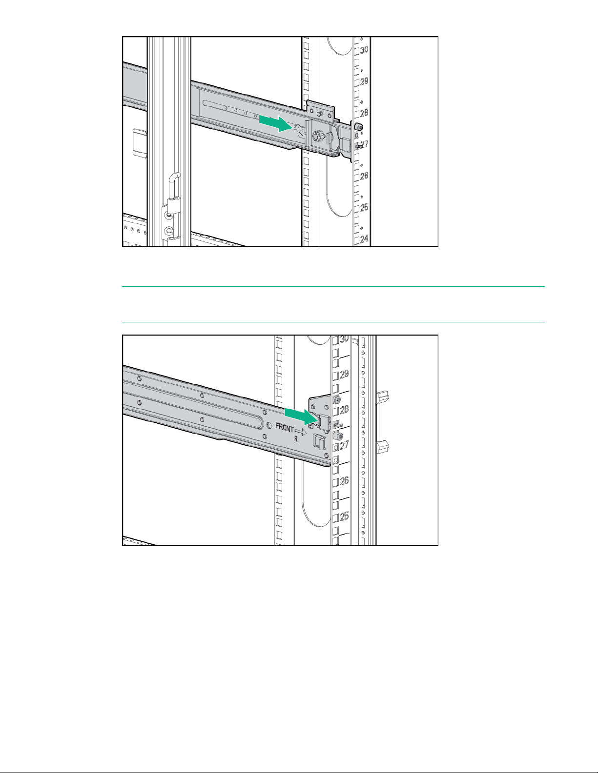
e. To engage the front rack rail mount, pull the rail towards the front of the rack to engage the spring
hook with the rack column in the same manner as the rear spring hook.
NOTE: Make sure that the respective guide pins for the square or round hole rack align properly
into rack column hole spacing.
f. Secure the rear of the rack rail to the rack column with the round- or square-hole shoulder screws
provided in the package.
60 HPE StoreOnce 5250 and 5650 Systems
Page 61
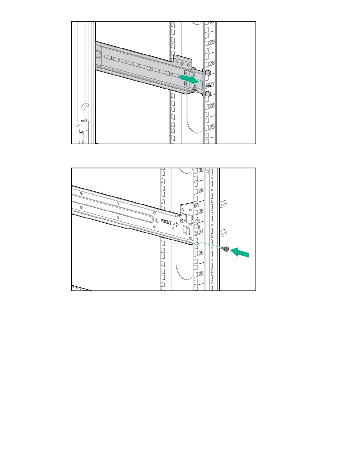
g. Secure front of the rack rail to the front rack column using the provided flat securing screw in the
bottom screw position of the rail.
h. Insert the eight locking nuts for the storage enclosure into the rack; two on each column.
To locate the position for the locking nuts, count up 4U from the bottom of the rails (1). Place a nut
on either side of the +4U position on each rack column (2).
HPE StoreOnce 5250 and 5650 Systems 61
Page 62

7. Install the base storage enclosure into the rack.
CAUTION: Use extreme caution when installing and pulling units from the rack. Unattached
units can slip and fall, damaging the StoreOnce System or causing personal injury. Hewlett
Packard Enterprise is not responsible for any damage or injury caused by mishandling the
StoreOnce system.
Always use at least two people to lift and locate an enclosure into the rack.
a. Verify that the storage enclosure has the correct JBOD number.
The storage enclosure has a pull-out tab in the upper left-hand corner of the rear panel. The tab
shows the JBOD number. In a system with multiple enclosures, having the correct JBOD numbers
on each pull-out tab will ease any necessary troubleshooting procedures.
• If the enclosure was part of the initial order, the JBOD number is pre-installed on the pull-out
tab.
• If the enclosure was not part of the initial order, apply the JBOD number from the sheet of
stickers to the pull-out tab.
b. Holding the handles, lift the storage enclosure onto the rails and push it into position.
The base enclosure has a JBOD label on rear of the enclosure. When installing the enclosures in
the rack, check the label to verify that you are installing the base enclosure (JBOD 1).
c. Tighten the thumbscrews to secure the enclosure to the rack.
62 HPE StoreOnce 5250 and 5650 Systems
Page 63

d. Attach a retaining bracket to each side of the rear of the storage enclosure and secure them to
the rack.
8. Use the supplied SAS cables to connect the first RAID controller card in the server node (slot 3) to
the base storage enclosure.
The supplied cables are labeled on both ends with the following convention.
• N = Node (server node)
• S = Slot
• P = Port
• J = JBOD
HPE StoreOnce 5250 and 5650 Systems 63
Page 64

• D = Drawer
4
3
1
2
• I = I/O module
Item SAS cable Label color Cable from To
1 0.5 m Red JBOD 1 Drawer 2 IOM A Port 1 JBOD 1 Drawer 1 IOM A Port 2
2 0.5 m Green JBOD 1 Drawer 2 IOM B Port 1 JBOD 1 Drawer 1 IOM B Port 2
3 1 m Red Node Slot 3 Port 1 JBOD 1 Drawer 1 IOM A Port 1
4 2 m Green Node Slot 3 Port 2 JBOD 1 Drawer 2 IOM B Port 2
9. Connect four power cables to the base enclosure. For each drawer, connect each power cable to a
different PDU.
10. Connect the server.
a. Connect the power cables.
Connect each power cable to a separate PDU in the rack.
b. Connect a network cable to LAN port 1.
c. Connect a network cable to the iLO port (recommended).
64 HPE StoreOnce 5250 and 5650 Systems
Page 65

d. Connect a VGA monitor and a USB keyboard for initial configuration.
11. Attach the security bezel to the front of the server.
a. Insert the security bezel right tab into the slot on the chassis and then rotate the bezel to close.
b. Lock the bezel.
The key to lock the bezel is attached to the back of the security bezel. One key is supplied.
HPE StoreOnce 5250 and 5650 Systems 65
Page 66

12. Verify the storage enclosure cable connections.
1
2
3
4
• Two SAS cables from the storage enclosure to the first RAID controller card (slot 3)
• Two 0.5 m SAS cables between the drawers on the storage enclosure.
• Four power cables to each storage enclosure.
13. Power on the StoreOnce System (the power button is on the front of the server).
• The power button LED flashes green at the start of the power-on sequence and then turns solid
green.
• The system health LED flashes green at the start of the power-on sequence and then turns solid
green.
• If LAN port 1 is connected to an active link, the NIC status LED will also begin to flash green
when the StoreOnce System is powering up.
• While configuring the system using iLO virtual console, the UID LED flashes blue.
Item Description
1 Power LED and on/off button
2 System health LED
3 NIC status LED
4 UID LED
After successful bootup, the console displays a login prompt.
14. Configure iLO during bootup (recommended).
Most iLO settings must be configured during bootup. The iLO network options can also be configured
with the System Manager.
66 HPE StoreOnce 5250 and 5650 Systems
Page 67

a. Press F9 System Utilities.
b. Navigate to System Configuration > iLO 5 Configuration > Network Options.
c. Configure the iLO network options and note the details.
iLO IP address:___________________________
iLO subnet mask:_________________________
iLO gateway:_____________________________
15. Configure the basic network.
By default, the system will have already attempted to obtain a DHCP address on LAN port 1. If you
already know the IP address that was assigned over DHCP, this step is optional.
a. Log in using the default user name and password.
Default user name: console
Default password: changeme
b. Change the console password to proceed.
Choose a secure password with at least eight characters that is memorable to you.
c. To configure a static address for LAN port 1 (eno1), select the Configure initial network
option from the console menu.
Note the DHCP assigned IP address or the static address details.
IP address:______________________________
Prefix length:_____________________________
Gateway:________________________________
DNS:________________________________
You can remove the console display and keyboard.
16. Open a web browser and use the IP address from the previous step to access the StoreOnce
system. The First Time Setup wizard is automatically displayed. Use the First Time Setup wizard to
configure the system for use.
The setup steps include:
• Setting the Administrator Password.
• Setting the Console Password.
• Setting basic System Information such as the system name (host name), location, and contact
information.
• Setting the System Date & Time. You can set the date and time manually, or synchronize the
date and time with a network time server.
• Configuring Storage. The wizard detects the factory installed storage. The wizard also enables
you to configure additional storage capacity that you might have installed. The wizard also reports
HPE StoreOnce 5250 and 5650 Systems 67
Page 68

issues with additional storage, for example, when additional storage is not installed in the correct
location.
• Configuring Remote Support.
Configuring a newly installed StoreOnce 5250 or 5650 system
If the system has capacity upgrade enclosures, you can install and configure them before or after
configuring the newly installed system. To install the capacity upgrade kits now, see
upgrade kits.
For additional information and instructions on each step, see the online help or user guide.
Procedure
1. Log on to the StoreOnce Management Console. Review and update the settings that were
configured with the First Time Setup Wizard.
• Administrator password
• System information, such as system, location, and contact information
• System date and time, or NTP configuration
Installing capacity
• Storage configuration
• Remote Support configuration
• Console password
2. Complete the network configuration.
On the main menu, select Settings. In the Hardware section, click the Networking panel.
For additional information, see Initial StoreOnce network configuration.
3. Redeem licenses, if necessary. Capacity or feature licenses ordered with the system will be
preinstalled. If ordered separately, redeem them now.
The capacity upgrade kit includes a license entitlement certificate. The certificate is a paper
document containing the information necessary to obtain your unique LTU (License to Use) key file
from the HPE Licensing website.
NOTE: Redeem licenses individually to obtain a license key file for each upgrade kit. Do not merge
multiple entitlements to redeem a single license key file.
IMPORTANT: You must add the licenses before expanding the capacity of the StoreOnce
System. The storage expansion process will not configure unlicensed storage attached to the
system.
a. On the main menu, select Settings.. From the System panel, select the License Management.
b. On the Overview tab, make a note of the Locking ID (Serial Number).
If you are managing the system through the federation lead, ensure that you are viewing the
correct system.
c. Go to the HPE Licensing website, as directed in the License Entitlement Certificate.
68 HPE StoreOnce 5250 and 5650 Systems
Page 69

d. Log in using your HPE Passport user ID and password.
e. Enter your Entitlement Order Number to search for your license.
f. Follow the steps to activate and obtain your license.
You can obtain the license file by downloading it directly from the website or from an email with
a .zip attachment.
g. Return to the License Management screen in the StoreOnce Management Console.
h. Expand the Actions menu ( ), click the Add License icon ( ), and then follow the onscreen
instructions.
4. Configure licenses, if necessary. Capacity or feature licenses ordered with the system will be
preinstalled. If ordered separately, configure them now.
a. On the main menu, select Settings.
b. In the Systems section, click the License Management panel.
• To view a license summary, click the Overview tab.
• To view a list of the installed licenses, click the Licenses tab.
For additional information, see Licensing.
5. Configure user accounts.
a. On the main menu, select Settings.
b. In the User Management section, click the Users and Groups panel panel.
• To add a user or group, select Add user or group on the Actions menu.
• To edit a user, click the user name.
• To remove a user, click the user name and then click Remove.
For additional information, see User roles and types.
6. Configure StoreOnce email alerts.
To display the configured email alerts, select Notifications from the Settings menu item.
7. Configure SNMP.
a. On the main menu, select Settings.
b. In the Notifications section, click the SNMP panel.
• To view summaries of the SNMP configuration, click the Overview tab. To view lists of the
items in the summaries, click the graphic segments and legends.
• To configure SNMP, select the tabs for Agent Setup, Trapsinks, and Users.
8. Apply an SSL certificate.
HPE StoreOnce 5250 and 5650 Systems 69
Page 70

a. On the main menu, select Settings.
b. In the Security section, click the Certificates panel.
c. On the Certificates screen, select Generate CSR on the Actions menu.
9. Expand storage, if necessary. Capacity upgrades ordered with the system will have already been
configured. If capacity upgrades were ordered separately, configure them now.
a. On the main menu, select Settings.
b. In the Hardware section, click the Storage panel.
c. On the Storage screen, click the Local Storage tab, and then expand the Actions ( ) menu
and select Rescan.
Newly detected storage is added to the storage list with a status of Unconfigured.
d. To configure the new storage for use, expand the Actions ( ) menu and select Configure.
10. Configure Remote Support using STaTS.
For additional information, see StoreOnce Remote Support.
11. Configure Fibre Channel.
For additional information, see Fibre Channel with StoreOnce Systems.
12. Configure iLO, if necessary.
If you plan to use iLO with the system and did not configure it during the system installation,
configure iLO now.
• View or update the iLO configuration from the StoreOnce Management Console.
a. On the main menu, select Settings.
b. In the Hardware section, click the Integrated Lights Out (iLO) Configuration panel.
The Integrated Lights Out (iLO) Configuration screen shows the HPE Integrated Lights Out
network configuration.
• In environments that do not use DHCP, DNS, or WINS, configure a static IP address during
bootup.
a. Restart or power on the StoreOnce Server.
b. Press F9 in the server POST screen.
The UEFI System Utilities start.
c. Navigate to System Configuration > iLO 5 Configuration > Network Options.
d. Configure the iLO network options and note the iLO IP address, iLO subnet mask, and iLO
gateway.
13. The StoreOnce 5250 or 5650 System is now installed and ready for production use.
70 HPE StoreOnce 5250 and 5650 Systems
Page 71

Installing capacity upgrade kits
This chapter contains instructions for adding a capacity upgrade kit to an existing system.
When installing a capacity upgrade kit during the initial system installation, see the instructions for your
system for a consolidated installation procedure.
•
Installing the StoreOnce 3620 System
• Installing the StoreOnce 3640 System
• Installing the StoreOnce 5200 System
• Installing the StoreOnce 5250 and 5650 Systems
Procedure
• HPE StoreOnce 3620 24 TB Capacity Upgrade Kit
• HPE StoreOnce 3640 48 TB Capacity Upgrade Kit
• HPE StoreOnce 5200 48 TB Capacity Upgrade Kit
• HPE StoreOnce 5250 and 5650 Capacity Upgrade Kits
◦ HPE StoreOnce 5250/5650 44 TB Capacity Upgrade Kit (disk pack)
◦ HPE StoreOnce 5250/5650 88 TB Capacity Upgrade Kit (disk pack)
◦ HPE StoreOnce 5250/5650 60 TB Drawer Upgrade Kit (storage enclosure)
◦ HPE StoreOnce 5250/5650 120 TB Drawer Upgrade Kit (storage enclosure)
HPE StoreOnce 3620 24 TB Capacity Upgrade Kit
Capacity upgrade kit contents
• Disk pack containing six 4 TB disks
• Capacity upgrade LTU (license)
• Read This First and Important cards
Enabling maintenance mode when using StoreOnce Remote Support
If StoreOnce Remote Support is configured, put the StoreOnce System into maintenance mode before
installing the upgrade. Enabling maintenance mode prevents the system from generating unwanted
support calls during the installation process.
Procedure
1. Navigate to the StoreOnce System and log in to the StoreOnce Management Console.
2. On the main menu, select Settings.
Installing capacity upgrade kits 71
Page 72

3. In the System section, select the Maintenance mode panel.
1
5
2
6
9 10
3 4
7 8
11 12
4. On the Maintenance mode screen, set the Maintenance mode switch to the On position ( ),
and then click OK.
Installing the StoreOnce 3620 Capacity Upgrade Kit
The system comes with six 4 TB disks already installed in the left six disk bays numbered 1, 2, 5, 6, 9,
and 10; the remaining disk bays are filled with blanking plates.
The capacity upgrade kit contains six 4 TB disks that you will install in the right six disk bays numbered 3,
4, 7, 8, 11, and 12.
NOTE: All six disks in the capacity upgrade kit must be installed before you can expand storage.
Figure 18: Disk bays populated before expansion
Procedure
1. Remove the front bezel from the StoreOnce System.
Remove the locking device to unlock the security bezel. Pull the bezel out and away from the front of
the appliance.
Figure 19: Removing the locking device
72 Installing capacity upgrade kits
Page 73

2
3
1
Figure 20: Removing the front bezel
1
2
1
2
2. Remove the blanking plates from the right six disk bays numbered 3, 4, 7, 8, 11, and 12. Push in the
latch (1) until it releases and pull out the plate (2).
NOTE: All six disks must be installed before you can expand storage.
Figure 21: Removing the blanking plates
3. Push the hard drive assembly into each drive bay (1) until it stops and press the HDD carrier latch (2)
inward until it clicks.
Figure 22: Installing the hard disk
4. Replace the front bezel when all six disks are installed, and install the locking device.
Installing capacity upgrade kits 73
Page 74

Figure 23: Replacing the front bezel
Figure 24: Installing the locking device
Completing the capacity upgrade
After all the capacity upgrade disks and enclosures have been installed, log on to the StoreOnce
Management Console as an administrator. Apply capacity licenses and then scan and configure the new
storage.
HPE StoreOnce 3640 48 TB Capacity Upgrade Kit
Introduction
The HPE StoreOnce 3640 System consists of a server with preconfigured storage on twelve 4 TB hard
disks. Use the following to expand your storage.
BB962A: HPE StoreOnce 3640 48 TB Capacity Upgrade Kit
74 Installing capacity upgrade kits
Page 75

The HPE StoreOnce 3640 System (48 TB) Capacity Upgrade Kit (BB962A) is a storage enclosure
containing twelve 4 TB disks. It includes a hot spare disk.
Up to two capacity upgrade kits may be added to the HPE StoreOnce 3640 System. A license is required
for each additional capacity upgrade kit and a license entitlement certificate is included with the kit, which
describes how to obtain the License To Use.
NOTE: The StoreOnce 3640 48 TB Capacity Upgrade Kit requires StoreOnce software version 4.1.0 or
higher and may only be used with the HPE StoreOnce 3640 System.
Capacity upgrade kit contents
• 2U storage enclosure containing one integrated SAS IO module and twelve 4 TB disks
• Rail kit
• One 0.5 m SAS cable
• Two power cords
• Capacity upgrade LTU (license)
• Read This First and Important cards
Planning for the capacity upgrade
The StoreOnce System remains available and the existing storage remains accessible during the
capacity upgrade process. However, HPE recommends the following:
• Schedule the capacity upgrade as a maintenance activity during a quiet period.
• Notify administrators of the upgrade plan.
• Check to see how any scheduled jobs, such as replication, might be affected by decreased
performance.
• Check the status of the existing storage and resolve any issues before proceeding with the capacity
upgrade.
The length of the upgrade process, including installing, cabling, licensing, and configuring the new
storage, depends on the size of the upgrade. The entire upgrade process can take 1-2 hours.
Enabling maintenance mode when using StoreOnce Remote Support
If StoreOnce Remote Support is configured, put the StoreOnce System into maintenance mode before
installing the upgrade. Enabling maintenance mode prevents the system from generating unwanted
support calls during the installation process.
Procedure
1. Navigate to the StoreOnce System and log in to the StoreOnce Management Console.
2. On the main menu, select Settings.
Installing capacity upgrade kits 75
Page 76
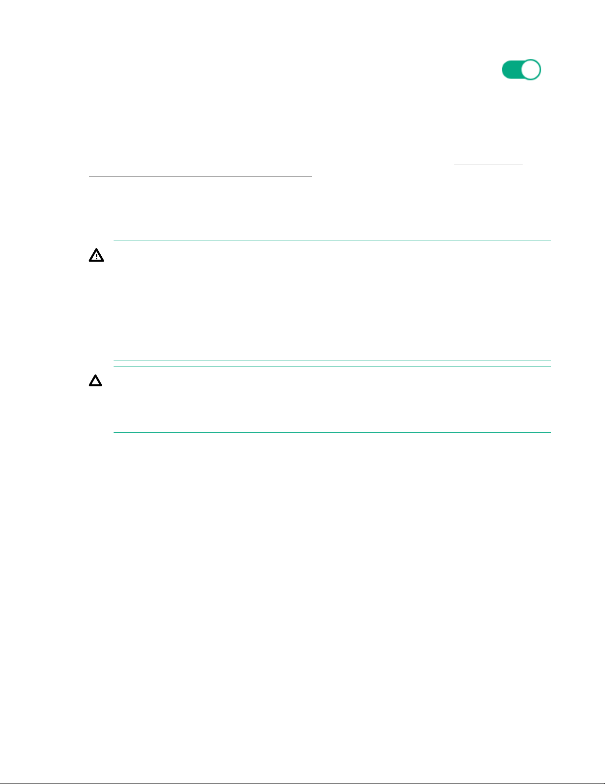
3. In the System section, select the Maintenance mode panel.
4. On the Maintenance mode screen, set the Maintenance mode switch to the On position ( ),
and then click OK.
Rack information
The storage enclosures can be installed into most standard server racks.
For detailed safety information, see the rack documentation and the safety guide at
support/Safety-Compliance-EnterpriseProducts.
Rack warnings
For detailed safety information, refer to the rack documentation and the Safety Guide provided with the
rack product.
WARNING: To reduce the risk of personal injury or damage to the equipment, be sure that:
• The leveling jacks are extended to the floor.
• The full weight of the rack rests on the leveling jacks.
• The stabilizing feet are attached to the rack of a single-rack installation.
• Only one component is extended at a time. A rack may become unstable if more than one
component is extended for any reason.
CAUTION: Use extreme caution when installing and pulling units from the rack. They can slip and
fall, damaging the StoreOnce System or causing personal injury.
HPE is not responsible for any injury or damage caused by the mishandling of the StoreOnce
System. Always use at least two people to lift and install an enclosure into the rack.
www.hpe.com/
Installing and connecting the capacity upgrade enclosures
Where to install the enclosure
Install the first capacity upgrade enclosure below the server node.
Install a second capacity upgrade enclosure below the first capacity upgrade enclosure.
76 Installing capacity upgrade kits
Page 77

1
2
3
Figure 25: StoreOnce 3640 System rack layout
Item Description
1 Server node
2 JBOD 1: First capacity upgrade kit. Install below the server node.
3 JBOD 2: Second capacity upgrade kit. Install below JBOD 1.
Installing the storage enclosure
Procedure
1. Install the enclosure rails in the rack.
a. Adjust the back bracket on the standard rail kit so it accommodates the storage enclosure. Attach
rear hold down brackets by sliding the tab with the arrow pointed forward (1) into the corresponding
slot on the left and right side of the rear of the chassis. Use the black headed thumb screw to
secure tightly to the rail in the second hole from the rear (2).
NOTE: It is easier to make this adjustment prior to mounting the rails.
Installing capacity upgrade kits 77
Page 78

b. Position left and right rack rails at the desired 'U' position in the rack, adjusting the rails to fit the
rack, as needed. Front and Rear bottom edge of rails must align with the bottom of EIA boundary in
the lowermost 'U'.
NOTE: Rails are marked L and R with an arrow indicating the direction in which the rail is installed.
c. Use guide pins to align the shelf mount kit to the rack column holes.
d. To engage the rear rack rail mount, push the rail toward the back of the rack until the spring hook
snaps into place.
e. To engage the front rack rail mount, pull the rail towards the front of the rack to engage the spring
hook with the rack column in the same manner as the rear spring hook.
NOTE: Make sure that the respective guide pins for the square or round hole rack align properly
into rack column hole spacing.
78 Installing capacity upgrade kits
Page 79

f. Secure the rear of the rack rail to the rack column with the round- or square-hole shoulder screws
provided in the package.
g. Secure front of the rack rail to the front rack column using the provided flat securing screw in the
bottom screw position of the rail.
Installing capacity upgrade kits 79
Page 80

2. Slide the enclosure into position on the rails (1). Secure the chassis into the rack by tightening the
1
2
3
captive CTO screw behind the latch on the front left and right bezel ears of the chassis (2).
CAUTION: The front CTO screw must be attached at all times when racked.
CAUTION: Use extreme caution when installing and pulling units from the rack. Unattached units
can slip and fall, damaging the StoreOnce System or causing personal injury. Hewlett Packard
Enterprise is not responsible for any damage or injury caused by mishandling the StoreOnce
system.
Always use at least two people to lift and locate an enclosure into the rack.
3. Attach rear hold down brackets by sliding the tab with the arrow pointed forward (1) into the
corresponding slot on the left and right side of the rear of the chassis. Use the black headed thumb
screw to secure tightly to the rail (2).
80 Installing capacity upgrade kits
Page 81

Labeling the cables
The StoreOnce capacity upgrade kit (enclosure) includes a sheet of preprinted cable label pairs. Each
pair contains two identical labels, one for each end of the SAS cable.
• N = Node (server node)
• S = Slot
• P = Port
• J = JBOD
• I = I/O module
Apply the correct pair of labels to each SAS cable as you cable the storage enclosure.
Cabling the first capacity upgrade kit (JBOD 1)
Procedure
1. Apply the "JBOD1" label to the top-left pull-out tab at the rear of the enclosure.
2. Apply the cable label to the new SAS cable.
SAS cable Label color New label
New 0.5 m cable Red N:S6:P1 - J1:I1:P1
3. Cable the enclosure as shown.
Installing capacity upgrade kits 81
Page 82

1
2
3
Figure 26: Cabling the first capacity upgrade kit (JBOD 1)
1
2
3
4
Item Description
1 Server node.
2 JBOD 1: First capacity upgrade kit.
Item SAS cable Label color Cable from To
3 New 0.5 m cable Red Node Slot 6 Port 1 JBOD 1 IOM 1 Port 1
4. If you are finished adding capacity upgrade kits, skip to Adding power cables.
Cabling the second capacity upgrade kit (JBOD 2) (StoreOnce 3640)
Procedure
1. Apply the "JBOD2" label to the top-left pull-out tab at the rear of the enclosure.
2. Label the cable that connects the second capacity upgrade kit to the system.
SAS cable Label color New label
New 0.5 m SAS cable Red J1:I1:P2 - J2:I1:P1
3. Cable the enclosure as shown.
Figure 27: Cabling the second capacity upgrade kit (JBOD 2)
82 Installing capacity upgrade kits
Page 83

Item Description
1 Server node.
2 JBOD 1: First capacity upgrade kit.
3 JBOD 2: Second capacity upgrade kit.
Item SAS cable Label color Cable from To
4 New 0.5 m cable Red JBOD 1 IOM 1 Port 2 JBOD 2 IOM 1 Port 1
4. Continue to Adding power cables.
Adding power cables and powering on the system
Procedure
1. Use the supplied power cables to connect the StoreOnce server to the mains power supply.
2. Use the supplied power cables to connect the capacity upgrade enclosure to the mains power supply.
IMPORTANT: Ensure that each power supply is connected to a separate PDU.
HPE StoreOnce 5200 48 TB Capacity Upgrade Kit
Introduction
The HPE StoreOnce 5200 System consists of a server node (containing operating system disks only) and
one storage enclosure with preconfigured storage on twelve 4 TB hard disks. Use the following to expand
the system storage.
BB964A: HPE StoreOnce 5200 48 TB Capacity Upgrade Kit
The capacity upgrade kit is a storage enclosure containing twelve 4 TB disks. It includes a hot spare disk.
Up to five capacity upgrade kits can be added to the StoreOnce 5200 System for a maximum of six
enclosures. A license is required for each capacity upgrade kit. A license entitlement certificate, which
describes how to obtain the License To Use, is included with the kit.
NOTE: The StoreOnce 5200 48 TB Capacity Upgrade Kit requires StoreOnce software version 4.1.0 or
higher and may only be used with the HPE StoreOnce 5200 System.
Capacity upgrade kit contents
• 2U storage enclosure containing two integrated SAS IO modules and twelve 4 TB disks
• Rail kit
• Two 0.5 m SAS cables
• One 1 m SAS cable
• One 2 m SAS cable
• Two power cords
Installing capacity upgrade kits 83
Page 84

• Capacity upgrade LTU (license)
• Read This First and Important cards
Planning for the capacity upgrade
The StoreOnce System remains available and the existing storage remains accessible during the
capacity upgrade process. However, HPE recommends the following:
• Schedule the capacity upgrade as a maintenance activity during a quiet period.
• Notify host users and administrators of the upgrade plan.
• Check to see how any scheduled jobs, such as replication, might be affected by decreased
performance.
• Check the status of the existing storage and resolve any issues before proceeding with the capacity
upgrade.
The length of the upgrade process, including installing, cabling, licensing, and configuring the new
storage, depends on the size of the upgrade. The entire process can take 1-3 hours to add new storage.
NOTE: Adding the third or more storage enclosure requires you to relocate one of the existing SAS
connections to the new enclosure. Follow the cabling instructions carefully and always ensure that no
more than one SAS cable at a time is disconnected throughout the upgrade process.
Powering off the system
See Rack warnings for information on safe handling of the enclosure.
WARNING: Always power off the StoreOnce System before powering off disk enclosures.
Procedure
1. Power off the StoreOnce System using the StoreOnce Management Console.
2. Power off all storage enclosures by disconnecting the power cables from the mains power.
Rack information
The storage enclosures can be installed into most standard server racks.
For detailed safety information, see the rack documentation and the safety guide at www.hpe.com/
support/Safety-Compliance-EnterpriseProducts.
Rack warnings
For detailed safety information, refer to the rack documentation and the Safety Guide provided with the
rack product.
84 Installing capacity upgrade kits
Page 85

WARNING: To reduce the risk of personal injury or damage to the equipment, be sure that:
• The leveling jacks are extended to the floor.
• The full weight of the rack rests on the leveling jacks.
• The stabilizing feet are attached to the rack of a single-rack installation.
• Only one component is extended at a time. A rack may become unstable if more than one
component is extended for any reason.
CAUTION: Use extreme caution when installing and pulling units from the rack. They can slip and
fall, damaging the StoreOnce System or causing personal injury.
HPE is not responsible for any injury or damage caused by the mishandling of the StoreOnce
System. Always use at least two people to lift and install an enclosure into the rack.
Installing and connecting the capacity upgrade enclosures
Preparing for the installation
Procedure
1. Unpack the capacity upgrade kit and verify the contents.
See StoreOnce 5200 Capacity Upgrade Kit (B964A) contents.
NOTE: For systems where the capacity upgrade kit has been pre-configured at the factory, locate the
label on the rear tab of the unit that identifies its position in the daisy chain sequence of storage
shelves.
2. Unpack the rail kit. Install the rail kit following the instructions supplied with the rail kit.
IMPORTANT: Read the installation guidelines carefully before installing the rails and the
expansion enclosure. The instructions provide important safety information.
NOTE: The installation instructions suggest adjusting the back bracket on the standard rail kit after
installing the rails. For ease of installation with the capacity upgrade kit, HPE recommends making the
adjustment prior to mounting the rail kit, as described in the next section.
3. Identify the rack location for the 2U capacity upgrade kit.
See Where to install the enclosure.
Enabling maintenance mode when using StoreOnce Remote Support
If StoreOnce Remote Support is configured, put the StoreOnce System into maintenance mode before
installing the upgrade. Enabling maintenance mode prevents the system from generating unwanted
support calls during the installation process.
Procedure
1. Navigate to the StoreOnce System and log in to the StoreOnce Management Console.
2. On the main menu, select Settings.
Installing capacity upgrade kits 85
Page 86

3. In the System section, select the Maintenance mode panel.
1
2
3
4
5
6
7
4. On the Maintenance mode screen, set the Maintenance mode switch to the On position ( ),
and then click OK.
Where to install the enclosure
Before installing the rails, plan where to put the capacity upgrade enclosure in the rack.
The base enclosure that comes with the system (JBOD 1) is installed immediately below the server node.
Install the first capacity upgrade enclosure (JBOD 2) immediately above the server node. Then alternate
below and above the server node as you add capacity upgrade enclosures to the system. A system at
maximum configuration has three storage enclosures below and three above the server node.
Figure 28: HPE StoreOnce 5200 System rack layout
Item Description
1 JBOD 6: Fifth capacity upgrade kit. Install above JBOD 4.
2 JBOD 4: Third capacity upgrade kit. Install above JBOD 2.
3 JBOD 2: First capacity upgrade kit. Install above the server.
4 Server node
5 JBOD 1: Base enclosure. Install under the server.
6 JBOD 3: Second capacity upgrade kit. Install under JBOD 1.
7 JBOD 5: Fourth capacity upgrade kit. Install under JBOD 3.
86 Installing capacity upgrade kits
Page 87

Installing the storage enclosure
Procedure
1. Install the enclosure rails in the rack.
a. Adjust the back bracket on the standard rail kit so it accommodates the storage enclosure. Attach
rear hold down brackets by sliding the tab with the arrow pointed forward (1) into the corresponding
slot on the left and right side of the rear of the chassis. Use the black headed thumb screw to
secure tightly to the rail in the second hole from the rear (2).
NOTE: It is easier to make this adjustment prior to mounting the rails.
b. Position left and right rack rails at the desired 'U' position in the rack, adjusting the rails to fit the
rack, as needed. Front and Rear bottom edge of rails must align with the bottom of EIA boundary in
the lowermost 'U'.
NOTE: Rails are marked L and R with an arrow indicating the direction in which the rail is installed.
c. Use guide pins to align the shelf mount kit to the rack column holes.
d. To engage the rear rack rail mount, push the rail toward the back of the rack until the spring hook
snaps into place.
Installing capacity upgrade kits 87
Page 88

e. To engage the front rack rail mount, pull the rail towards the front of the rack to engage the spring
hook with the rack column in the same manner as the rear spring hook.
NOTE: Make sure that the respective guide pins for the square or round hole rack align properly
into rack column hole spacing.
f. Secure the rear of the rack rail to the rack column with the round- or square-hole shoulder screws
provided in the package.
88 Installing capacity upgrade kits
Page 89

g. Secure front of the rack rail to the front rack column using the provided flat securing screw in the
bottom screw position of the rail.
2. Slide the enclosure into position on the rails (1). Secure the chassis into the rack by tightening the
captive CTO screw behind the latch on the front left and right bezel ears of the chassis (2).
CAUTION: The front CTO screw must be attached at all times when racked.
CAUTION: Use extreme caution when installing and pulling units from the rack. Unattached units
can slip and fall, damaging the StoreOnce System or causing personal injury. Hewlett Packard
Enterprise is not responsible for any damage or injury caused by mishandling the StoreOnce
system.
Always use at least two people to lift and locate an enclosure into the rack.
Installing capacity upgrade kits 89
Page 90
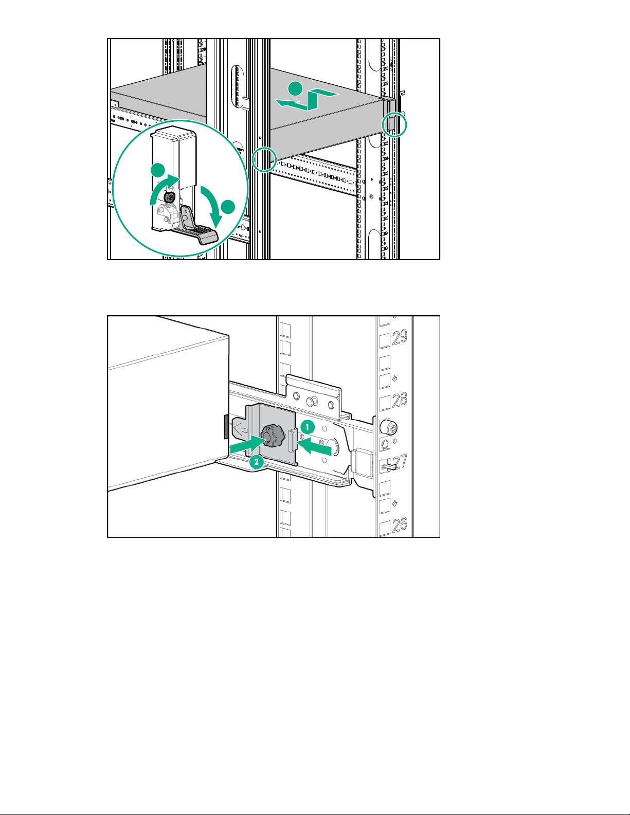
1
2
3
3. Attach rear hold down brackets by sliding the tab with the arrow pointed forward (1) into the
corresponding slot on the left and right side of the rear of the chassis. Use the black headed thumb
screw to secure tightly to the rail (2).
Cabling capacity upgrade enclosures
Labeling the cables
The StoreOnce capacity upgrade kit (enclosure) includes a sheet of preprinted cable label pairs. Each
pair contains two identical labels, one for each end of the SAS cable.
• N = Node (server node)
• S = Slot
• P = Port
• J = JBOD
• I = I/O module
90 Installing capacity upgrade kits
Page 91

Apply the correct pair of labels to each SAS cable as you cable the storage enclosure.
1
2
3
4
5
Cabling the first capacity upgrade kit (JBOD 2)
The first capacity upgrade kit is located directly above the server node.
Procedure
1. Apply the "JBOD2" label to the top-left pull-out tag at the rear of the enclosure.
2. Apply the cable labels to the new SAS cables.
SAS cable Label color Cable label
New 1 m cable Red N:S6:P1 - J2:I1:P1
New 2 m cable Green N:S6:P2 - JF:I2:P1
White F=2
3. Cable the enclosure as shown.
Figure 29: Cabling the first capacity upgrade kit (JBOD 2)
Item Description
1 JBOD 2: First capacity upgrade kit.
2 Server node.
3 JBOD 1: Base enclosure.
Item SAS cable Label colors Cable from To
4 New 1 m cable Red Node Slot 6 Port 1 JBOD 2 IOM 1 Port 1
5 New 2 m cable Green and White Node Slot 6 Port 2 JBOD 2 IOM 2 Port 1
4. If you are finished installing capacity upgrade kits, skip to Adding power cables.
Cabling the second capacity upgrade kit (JBOD 3)
The second capacity upgrade kit is located directly under JBOD 1.
Installing capacity upgrade kits 91
Page 92

Procedure
1
2
3
4
5
6
7
1. Apply the "JBOD3" label to the top-left pull-out tag at the rear of the enclosure.
2. Apply the cable labels to the new SAS cables. On the moving SAS cable, replace the "F=1" label with
the "F=3" label.
SAS cable Label color New label
New 0.5 m cable Red J1:I1:P2 - J3:I1:P1
New 0.5 m cable Green J3:I2:P2 - J1:I2:P1
Moving 2 m cable (N:S3:P2 - JF:I2:P1) White F=3
3. Cable the enclosure as shown.
Figure 30: Cabling the second capacity upgrade kit (JBOD 3)
Item Description
1 JBOD 2: First capacity upgrade kit.
2 Server node.
3 JBOD 1: Base enclosure.
4 JBOD 3: Second capacity upgrade kit.
Item SAS cable Label colors Cable from To
5 New 0.5 m cable Red JBOD 1 IOM 1 Port 2 JBOD 3 IOM 1 Port 1
6 New 0.5 m cable Green JBOD 3 IOM 2 Port 2 JBOD 1 IOM 2 Port 1
7 Moving 2 m cable Green and white Node Slot 3 Port 2 JBOD 3 IOM 2 Port 1
4. If you are finished installing capacity upgrade kits, skip to Adding power cables.
92 Installing capacity upgrade kits
Page 93

Cabling the third capacity upgrade kit (JBOD 4)
1
2
3
4
5
6
7
8
The third capacity upgrade kit is located directly above JBOD 2.
Procedure
1. Apply the "JBOD4" label to the top-left pull-out tag at the rear of the enclosure.
2. Apply the cable labels to the new SAS cables. On the moving SAS cable, replace the "F=2" label with
the "F=4" label.
SAS cable Label color New label
New 0.5 m cable Red J2:I1:P2 - J4:I1:P1
New 0.5 m cable Green J4:I2:P2 - J2:I2:P1
Moving 2 m cable (N:S6:P2 - JF:I2:P1) White F=4
3. Cable the enclosure as shown.
Figure 31: Cabling the third capacity upgrade kit (JBOD 4)
Item Description
1 JBOD 4: Third capacity upgrade kit.
2 JBOD 2: First capacity upgrade kit.
3 Server node.
4 JBOD 1: Base enclosure.
5 JBOD 3: Second capacity upgrade kit.
Installing capacity upgrade kits 93
Page 94

Item SAS cable Label colors Cable from To
1
2
3
4
5
6
7
8
9
6 New 0.5 m cable Red JBOD 2 IOM 1 Port 2 JBOD 4 IOM 1 Port 1
7 New 0.5 m cable Green JBOD 4 IOM 2 Port 2 JBOD 2 IOM 2 Port 1
8 Moving 2 m cable Green and white Node Slot 6 Port 2 JBOD 4 IOM 2 Port 1
4. If you are finished installing capacity upgrade kits, skip to Adding power cables.
Cabling the fourth capacity upgrade kit (JBOD 5)
The fourth capacity upgrade kit is the lowest in the rack, located directly below JBOD 3.
Procedure
1. Apply the "JBOD5" label to the top-left pull-out tag at the rear of the enclosure.
2. Apply the cable labels to the new SAS cables. On the moving SAS cable, replace the "F=3" label with
the "F=5" label.
SAS cable Label color New label
New 0.5 m cable Red J3:I1:P2 - J5:I1:P1
New 0.5 m cable Green J5:I2:P2 - J3:I2:P1
Moving 2 m cable (N:S3:P2 - JF:I2:P1) White F=5
3. Cable the enclosure as shown.
94 Installing capacity upgrade kits
Figure 32: Cabling the fourth capacity upgrade kit (JBOD 5)
Page 95

Item Description
1 JBOD 4: Third capacity upgrade kit.
2 JBOD 2: First capacity upgrade kit.
3 Server node.
4 JBOD 1: Base enclosure.
5 JBOD 3: Second capacity upgrade kit.
6 JBOD 5: Fourth capacity upgrade kit.
Item SAS cable Label colors Cable from To
7 New 0.5 m cable Red JBOD 3 IOM 1 Port 2 JBOD 5 IOM 1 Port 1
8 New 0.5 m cable Green JBOD 5 IOM 2 Port 2 JBOD 3 IOM 2 Port 1
9 Moving 2 m cable Green and white Node Slot 3 Port 2 JBOD 5 IOM 2 Port 1
4. If you are finished installing capacity upgrade kits, skip to Adding power cables.
Cabling the fifth capacity upgrade kit (JBOD 6)
The fifth capacity upgrade kit is the highest in the rack, located directly above JBOD 4.
Procedure
1. Apply the "JBOD6" label to the top-left pull-out tag at the rear of the enclosure.
2. Apply the cable labels to the new SAS cables. On the moving SAS cable, replace the "F=4" label with
the "F=6" label.
SAS cable Label color New label
New 0.5 m cable Red J4:I1:P2 - J6:I1:P1
New 0.5 m cable Green J6:I2:P2 - J4:I2:P1
Moving 2 m cable (N:S6:P2 - JF:I2:P1) White F=6
3. Cable the enclosure as shown.
Installing capacity upgrade kits 95
Page 96

1
2
3
4
5
6
7
8
9
10
Figure 33: Cabling the fifth capacity upgrade kit (JBOD 6)
Item Description
1 JBOD 6: Fifth capacity upgrade kit.
2 JBOD 4: Third capacity upgrade kit.
3 JBOD 2: First capacity upgrade kit.
4 Server node.
5 JBOD 1: Base enclosure.
6 JBOD 3: Second capacity upgrade kit.
7 JBOD 5: Fourth capacity upgrade kit.
Item SAS cable Label colors Cable from To
8 New 0.5 m cable Red JBOD 4 IOM 1 Port 2 JBOD 6 IOM 1 Port 1
9 New 0.5 m cable Green JBOD 6 IOM 2 Port 2 JBOD 4 IOM 2 Port 1
10 Moving 2 m cable Green and white Node Slot 6 Port 2 JBOD 6 IOM 2 Port 1
4. Continue to Adding power cables.
Adding power cables
Procedure
1. Use the supplied power cables to connect the capacity upgrade enclosure to the mains power supply.
96 Installing capacity upgrade kits
Page 97

The enclosure powers on automatically when plugged in. Wait for a minute for the power on process to
complete. The System Power and Status LEDs will be solid green.
2. If you powered off the StoreOnce System before adding capacity upgrade kits, power on the system.
HPE StoreOnce 5250 and 5650 Capacity Upgrade Kits
Introduction
The HPE StoreOnce 5250 and 5650 Systems consist of:
• A server node (containing operating system disks only)
• One 5U storage enclosure with preconfigured storage on 15 hard disks, 4 TB or 8 TB
Use the following options to expand your storage:
• BB974A: HPE StoreOnce 5250/5650 44 TB Capacity Upgrade Kit
One disk pack containing eleven 4 TB disks. Add the disk packs to the base enclosure and to capacity
upgrade enclosures as described in this guide. You can add up to five 44 TB disk packs to a BB966A
enclosure for a total of 70 disks in each enclosure.
All disks in the enclosure must be the same capacity. Do not install this capacity upgrade kit in the
BB968A 120 TB enclosure.
• BB976A: HPE StoreOnce 5250/5650 88 TB Capacity Upgrade Kit
One disk pack containing eleven 8 TB disks. Add the disk packs to the base enclosure and to capacity
upgrade enclosures as described in this guide. You can add up to five 88 TB disk packs to a BB968A
enclosure for a total of 70 disks in each enclosure.
All disks in the enclosure must be the same capacity. Do not install this capacity upgrade kit in the
BB966A 60 TB enclosure.
• BB966A: HPE StoreOnce 5250/5650 60 TB Drawer Upgrade Kit
One 5U storage enclosure containing fifteen 4 TB disks. Once you have filled all the bays in the base
enclosure using the applicable disk packs, you can add new enclosures to your system. Use the
BB974A disk packs to completely fill the existing enclosure before adding another enclosure. The
StoreOnce 5250 System supports a maximum of one upgrade storage enclosure in addition to the
base storage enclosure. The StoreOnce 5650 System supports a maximum of three upgrade storage
enclosures in addition to the base storage enclosure.
• BB968A: HPE StoreOnce 5250/5650 120 TB Drawer Upgrade Kit
One 5U storage enclosure containing fifteen 8 TB disks. Once you have filled all the bays in the base
enclosure using the applicable disk packs, you can add new enclosures to your system. Use the
BB976A disk packs to completely fill the existing enclosure before adding another enclosure. The
StoreOnce 5250 System supports a maximum of one upgrade storage enclosure in addition to the
base storage enclosure. The StoreOnce 5650 System supports a maximum of three upgrade storage
enclosures in addition to the base storage enclosure.
Upgrade kit contents
Capacity upgrade kit, BB974A and BB976A disk pack:
Installing capacity upgrade kits 97
Page 98

• Disk pack containing eleven 4 TB or 8 TB disks
• Capacity upgrade LTU (license)
• Read This First and Important cards
Drawer upgrade kit, BB966A and BB968A enclosure:
• 5U storage enclosure containing fifteen 4 TB or 8 TB disks
• Rail kit
• Two 0.5 m cables
• Two 1 m cables
• One 2 m cable
• Four power cords
• Capacity upgrade LTU (license)
• Read This First and Important cards
Capacity upgrade process overview
Procedure
1. Plan the capacity upgrade process.
2. Enable maintenance mode when using StoreOnce Remote Support.
3. If necessary, reposition the StoreOnce System in the rack to accommodate the new upgrade storage
enclosure. Power off the system before removing components from the rack.
4. Install upgrade storage enclosures.
a. Install the enclosure.
b. Label and cable the enclosure.
5. Install capacity upgrade disk packs.
6. Complete the capacity upgrade process.
a. Redeem and add the licenses.
b. Scan and configure storage.
c. Check the hardware and firmware.
d. Disable maintenance mode.
Planning for the capacity upgrade
The StoreOnce System remains available and the existing storage remains accessible during the
capacity upgrade process. However, HPE recommends the following:
98 Installing capacity upgrade kits
Page 99

• Schedule the capacity upgrade as a maintenance activity during a quiet period.
• Notify host users and administrators of the upgrade plan.
• Check to see how any scheduled jobs, such as replication, might be affected by decreased
performance.
• Check the status of the existing storage and resolve any issues before proceeding with the capacity
upgrade.
The length of the upgrade process, including installing, labeling and cabling, licensing, and configuring
the new storage, depends on the upgrade. The entire process can take from 30 minutes when only
adding disk packs to 2-3 hours when adding storage enclosures.
NOTE: Adding a third or fourth storage enclosure requires you to relocate one of the existing SAS
connections to the new enclosure. Follow the cabling instructions carefully and always ensure that no
more than one SAS cable at a time is disconnected throughout the upgrade process.
Enabling maintenance mode when using StoreOnce Remote Support
If StoreOnce Remote Support is configured, put the StoreOnce System into maintenance mode before
installing the upgrade. Enabling maintenance mode prevents the system from generating unwanted
support calls during the installation process.
Procedure
1. Navigate to the StoreOnce System and log in to the StoreOnce Management Console.
2. On the main menu, select Settings.
3. In the System section, select the Maintenance mode panel.
4. On the Maintenance mode screen, set the Maintenance mode switch to the On position ( ),
and then click OK.
Powering off the system
Capacity expansion does not require you to power off the StoreOnce System. However, as a precaution,
you can power off when expanding to more than two enclosures. Expansion to the third or fourth
enclosure requires moving one of the existing SAS cables. You might also need to power off the
StoreOnce System to reposition equipment within the rack.
See Rack warnings for information on safe handling of the enclosure.
WARNING: Always power off the StoreOnce System before powering off storage enclosures.
Procedure
1. Power off the StoreOnce System using the StoreOnce Management Console.
2. Power off all storage enclosures. Press and hold the power button on the rear of each enclosure.
Rack information
The storage enclosures can be installed into most standard server racks. To verify that your rack is
supported for use with the storage enclosure, see the QuickSpecs for the enclosure available at: http://
Installing capacity upgrade kits 99
Page 100

www.hpe.com/support/StoreOnceQuickSpecs. Click Search Active QuickSpecs. In the Search box,
enter "D3000 enclosures" (for StoreOnce models 3640 and 5200) or "D6020 enclosure" (for StoreOnce
models 5250 and 5650), select Search only in title, then click Go.
Always refer to the rack documentation and the safety guide at www.hpe.com/support/Safety-
Compliance-EnterpriseProducts for detailed safety information.
Rack warnings
For detailed safety information, refer to the rack documentation and the Safety Guide provided with the
rack product.
WARNING: To reduce the risk of personal injury or damage to the equipment, be sure that:
• The leveling jacks are extended to the floor.
• The full weight of the rack rests on the leveling jacks.
• The stabilizing feet are attached to the rack of a single-rack installation.
• Only one component is extended at a time. A rack may become unstable if more than one
component is extended for any reason.
CAUTION: Use extreme caution when installing and pulling units from the rack. They can slip and
fall, damaging the StoreOnce System or causing personal injury.
HPE is not responsible for any injury or damage caused by the mishandling of the StoreOnce
System. Always use at least two people to lift and install an enclosure into the rack.
Space requirements
Sufficient space is required to the front and to the right-hand side of the rack to ensure that there is
enough clearance to maneuver the disks in and out of drawer 2.
• To the front — approximately 43 inches (1080 mm) from the inside of the front rack column.
• To the right — at least 12 inches (300 mm),
100 Installing capacity upgrade kits
 Loading...