

HP StoreOnce 3100, StoreOnce 3500, StoreOnce 5100, StoreOnce 5500 Installation And Configuration Manual
Page 1

HPE StoreOnce 3100, 3500, 5100, and 5500 System Installation and Configuration Guide
Abstract
This guide is for HPE StoreOnce System Administrators. It assumes that the user has
followed the instructions on the appropriate Start Here poster to create a basic network
connection to the HPE StoreOnce System.
Part Number: BB913-90964
Published: April 2018
Edition: 4
Page 2

©
Copyright 2015-2017, 2018 Hewlett Packard Enterprise Development LP
Notices
The information contained herein is subject to change without notice. The only warranties for Hewlett
Packard Enterprise products and services are set forth in the express warranty statements accompanying
such products and services. Nothing herein should be construed as constituting an additional warranty.
Hewlett Packard Enterprise shall not be liable for technical or editorial errors or omissions contained
herein.
Confidential computer software. Valid license from Hewlett Packard Enterprise required for possession,
use, or copying. Consistent with FAR 12.211 and 12.212, Commercial Computer Software, Computer
Software Documentation, and Technical Data for Commercial Items are licensed to the U.S. Government
under vendor's standard commercial license.
Links to third-party websites take you outside the Hewlett Packard Enterprise website. Hewlett Packard
Enterprise has no control over and is not responsible for information outside the Hewlett Packard
Enterprise website.
Acknowledgments
Intel®, Itanium®, Pentium®, Intel Inside®, and the Intel Inside logo are trademarks of Intel Corporation in
the United States and other countries.
Microsoft® and Windows® are either registered trademarks or trademarks of Microsoft Corporation in the
United States and/or other countries.
Adobe® and Acrobat® are trademarks of Adobe Systems Incorporated.
Java® and Oracle® are registered trademarks of Oracle and/or its affiliates.
UNIX® is a registered trademark of The Open Group.
Page 3

Contents
Preparing for Basic Configuration ....................................................... 7
SAS cabling for HPE StoreOnce 5500 Systems................................. 12
Structure of the StoreOnce guide................................................................................................. 7
Overview of StoreOnce configuration tasks..................................................................................7
HPE StoreOnce Systems .............................................................................................................8
HPE StoreOnce 5500 System............................................................................................8
HPE StoreOnce 3100 System............................................................................................9
HPE StoreOnce 3500 Series............................................................................................. 9
HPE StoreOnce 5100 System............................................................................................9
Verifying the HPE StoreOnce hardware configuration................................................................10
Other sources of information for HPE StoreOnce Systems........................................................ 10
Cabling considerations for HPE StoreOnce 5500 Systems........................................................ 12
Basic HPE StoreOnce 5500 System installation.........................................................................12
SAS cable lengths for HPE StoreOnce Systems........................................................................ 13
Expansion installation scenarios.................................................................................................14
Connecting enclosures.....................................................................................................14
Daisy chaining enclosures............................................................................................... 15
Two enclosures above and two enclosures below the server..........................................15
Up to four enclosures below the server............................................................................16
Factory-integrated SAS cabling configuration..................................................................18
Powering up and setting up iLO4........................................................ 20
Powering up the HPE StoreOnce 5500 System......................................................................... 20
Powering up StoreOnce 3100, 3500 and 5100 Systems............................................................ 21
iLO network name and iLO password.........................................................................................23
Configuring iLO4, all systems..................................................................................................... 23
Basic network configuration........................................................................................................ 27
Logging in to the HPE StoreOnce System and checking status...... 28
Supported web browsers............................................................................................................ 28
Logging in to the HPE StoreOnce System and checking status................................................. 28
Accessing the StoreOnce CLI.....................................................................................................29
The StoreOnce login banner.......................................................................................................29
Setting up a login banner................................................................................................. 30
Configuring Remote Support...............................................................31
StoreOnce Remote Support .......................................................................................................31
Setting up Remote Support on the StoreOnce Management GUI.............................................. 31
More about warranty details........................................................................................................32
HPE StoreOnce Configuration Wizard................................................ 33
Purpose of the HPE StoreOnce Configuration Wizard............................................................... 33
Using the StoreOnce Configuration Wizard................................................................................ 33
Contents 3
Page 4

Configuring licenses.............................................................................34
Capacity expansion license for StoreOnce 5500........................................................................ 34
Pre-installed Capacity licenses........................................................................................ 34
Capacity expansion license for HPE StoreOnce 3500 Series and HPE StoreOnce 5100
System........................................................................................................................................ 34
Security license...........................................................................................................................35
Target devices and Catalyst stores licenses...............................................................................35
StoreOnce Optional Hardware licenses......................................................................................35
Checking for installed licenses....................................................................................................36
Applying a demo license............................................................................................................. 36
StoreOnce full license................................................................................................................. 37
Redeeming a license........................................................................................................37
Applying a full license.......................................................................................................38
Setting time zone and configuring NTP server.................................. 39
Using the StoreOnce GUI to set the time zone ..........................................................................39
Using the StoreOnce GUI to configure NTP server.................................................................... 39
Creating user accounts and changing default passwords............... 41
StoreOnce user accounts........................................................................................................... 41
Adding a local user..................................................................................................................... 41
Changing passwords for local users........................................................................................... 42
Setting up StoreOnce email alerts.......................................................43
Email setup page........................................................................................................................ 43
Configuring email settings...........................................................................................................43
Testing email...............................................................................................................................43
Email Events notification.............................................................................................................43
Managing email notifications............................................................................................44
Setting up SNMP (Simple Network Management Protocol) ............. 46
Management Information Bases (MIBs)..................................................................................... 46
Setting up the Network Management application for use with the StoreOnce System...............46
Configuring SNMP on the StoreOnce GUI..................................................................................46
Generating the SSL certificate.............................................................49
SSL certificates........................................................................................................................... 49
Generating a self-signed certificate............................................................................................ 49
Expanding storage capacity, if supported..........................................50
HPE StoreOnce 3500 Series...................................................................................................... 50
Viewing license details..................................................................................................... 50
Viewing storage status..................................................................................................... 50
StoreOnce 5100 System and HPE StoreOnce 5500 System..................................................... 52
4 Contents
Checking for the latest software..........................................................53
Checking the StoreOnce software version..................................................................................53
Page 5

Remote event reporting.............................................................................................................. 53
Viewing and upgrading firmware.................................................................................................53
Complete network configuration......................................................... 55
Initial StoreOnce network configuration...................................................................................... 55
Creating a StoreOnce custom network configuration overview.................................................. 55
Creating a new StoreOnce configuration and defining DNS servers.......................................... 56
Creating portsets.........................................................................................................................58
Creating subnets.........................................................................................................................60
Validating and activating the StoreOnce configuration................................................................61
Additional configuration tasks............................................................ 63
Post StoreOnce configuration..................................................................................................... 63
Saving the StoreOnce configuration and keystore .....................................................................63
Contents of the StoreOnce configuration file................................................................... 63
Saving the StoreOnce configuration................................................................................ 63
The StoreOnce encryption keystore.................................................................................63
Running a StoreOnce system confidence check ....................................................................... 64
Defining a new remote host to receive StoreOnce audit log events........................................... 65
Aggregating login event notifications.......................................................................................... 65
Configuring media servers to use StoreOnce Catalyst............................................................... 66
Drivers for StoreOnce VTL devices on client servers................................................................. 66
iSCSI Initiator (StoreOnce VTL)..................................................................................................67
Hardware overview reference section.................................................68
Optional hardware.......................................................................................................................68
HPE StoreOnce 5500 System.................................................................................................... 68
HPE StoreOnce 5500 System front and rear views, server............................................. 68
Front and rear views of the disk enclosure...................................................................... 69
Storage expansion .......................................................................................................... 70
HPE StoreOnce 3100 System.................................................................................................... 70
HPE StoreOnce 3500 Series...................................................................................................... 71
Front and rear views ........................................................................................................72
Storage expansion........................................................................................................... 72
HPE StoreOnce 5100 System.................................................................................................... 73
Front and rear views.........................................................................................................73
Storage expansion...................................................................................................................... 74
Optional PCIe cards.............................................................................. 76
StoreOnce Optional Hardware with StoreOnce 35xx and 5xxx models......................................76
PCIe slot allocation at delivery....................................................................................................76
Port numbering on PCI cards...........................................................................................77
Viewing Optional Hardware configuration...................................................................................78
Network reference information............................................................ 79
More about network configuration...............................................................................................79
Understanding hardware configuration options.......................................................................... 79
1 GbE network connections............................................................................................. 79
10 GbE network connections........................................................................................... 79
Key network definitions............................................................................................................... 80
Network bonding modes............................................................................................................. 81
Contents 5
Page 6

VLAN guidelines with StoreOnce systems..................................................................................82
Fibre Channel with StoreOnce Systems............................................. 84
Fibre Channel hardware requirements....................................................................................... 84
Supported Fibre Channel connections........................................................................................84
Zoning.............................................................................................................................. 84
Configuring Fibre Channel.......................................................................................................... 85
For use with StoreOnce Catalyst stores...........................................................................85
For use with VTL libraries.................................................................................................86
Support and other resources...............................................................87
Accessing Hewlett Packard Enterprise Support......................................................................... 87
Accessing updates......................................................................................................................87
Customer self repair....................................................................................................................88
Remote support.......................................................................................................................... 88
Warranty information...................................................................................................................88
Regulatory information................................................................................................................89
Documentation feedback............................................................................................................ 89
Additional regulatory information....................................................... 90
Belarus Kazakhstan Russia marking.......................................................................................... 90
Turkey RoHS material content declaration................................................................................. 91
Ukraine RoHS material content declaration................................................................................91
6 Contents
Page 7
Preparing for Basic Configuration
Structure of the StoreOnce guide
This guide assumes that the user has followed the instructions on the printed Start Here poster to install
the HPE StoreOnce System in the Data Center and establish an initial 1 GbE network connection for the
StoreOnce Management Console.
IMPORTANT:
All tasks described in this guide require an admin user logon.
The guide is divided into two sections. The first section is task based and describes how to log in to the
StoreOnce GUI to complete basic configuration tasks. The second section provides reference information
for the hardware and physical connection to Ethernet or Fibre Channel.
Overview of StoreOnce configuration tasks
Table 1: Configuration checklist
Task Refer to
1 The Start Here poster describes a basic installation
with connection to LAN port 1, which is valid for all
products. Make sure you understand what is
factory installed and configured on your system
and any further cabling requirements. Available
options for network and Fibre Channel connectivity
will depend upon the type of model.
2 Make sure all reference material is available.
3 StoreOnce 5500 only: Review SAS cabling
requirements.
4 Boot up the system and, if you are using a Network
Management application, such as Insight Remote
Support, configure iLO. (You can also configure
iLO after configuring the StoreOnce System.)
5 Log on to the StoreOnce Management Console
and check system, storage and optional hardware
status.
6 Configure licenses.
Hardware overview reference section on
page 68
Other sources of information for HPE
StoreOnce Systems on page 10
SAS cabling for HPE StoreOnce 5500
Systems on page 12
Powering up and setting up iLO4 on page
20
Logging in to the HPE StoreOnce System
and checking status on page 28
Configuring licenses on page 34
7 Configure time zone and NTP server.
8 Configure users.
Setting time zone and configuring NTP
server on page 39
Creating user accounts and changing
default passwords on page 41
Table Continued
Preparing for Basic Configuration 7
Page 8
Task Refer to
9 Configure email.
10 Configure SNMP.
11 Apply the SSL certificate.
12 If necessary, expand storage.
13 Check software version.
14 Configure Remote Support via STaTS.
15 Configure the network.
16 Configure Fibre Channel.
17 Complete configuration.
18 Use the StoreOnce CLI to run a confidencecheck
report on the system.
Setting up StoreOnce email alerts on page
43
Setting up SNMP (Simple Network
Management Protocol) on page 46
Generating the SSL certificate on page
49
Expanding storage capacity, if supported
on page 50
Checking for the latest software on page
53
Configuring Remote Support on page 31
Complete network configuration on page
55
Fibre Channel with StoreOnce Systems on
page 84
Additional configuration tasks on page
63
Running a StoreOnce system confidence
check on page 64
HPE StoreOnce Systems
HPE StoreOnce 5500 System
Table 2: HPE StoreOnce 5500 System
Storage capacity 60 TB (11 x 4 TB disks + 4 hot spare)
Storage Expansion Options There are two options:
StoreOnce Optional Hardware Four PCIe slots are available for 10 GbE Network
Maximum capacity = 1120 TB
Add up to five 44 TB Capacity Upgrade disk packs
(containing eleven 4 TB disks) to each enclosure
Add up to three 60 TB Capacity Upgrade disk
enclosures (containing eleven 4 TB disks + 4 hot
spare)
and FC PCIe cards.
See Optional PCIe cards on page 76.
8 HPE StoreOnce Systems
Page 9

HPE StoreOnce 3100 System
Table 3: HPE StoreOnce 3100 System
Storage capacity 8 TB (4 x 2 TB disks)
Storage Expansion Options None
StoreOnce Optional Hardware Not supported
HPE StoreOnce 3500 Series
Table 4: HPE StoreOnce 3520 System
Storage capacity 12/24 TB (12 x 2 TB disks)
Storage Expansion Options 24 TB (100% capacity) requires additional license
StoreOnce Optional Hardware Four PCIe slots are available for 10 GbE Network
Base storage = 12 TB (50% capacity)
and FC PCIe cards.
See Optional PCIe cards on page 76.
Table 5: HPE StoreOnce 3540 System
Storage capacity 24/48 TB (12 x 4 TB disks)
Storage Expansion Options 48 TB (100% capacity) requires additional license
StoreOnce Optional Hardware Four PCIe slots are available for 10 GbE Network
HPE StoreOnce 5100 System
Table 6: HPE StoreOnce 5100 System
Storage capacity 48 TB (12 x 4 TB disks)
Storage Expansion Options Up to five 48 TB Capacity Upgrade Kits may be
Base storage = 24 TB (50% capacity)
and FC PCIe cards.
See Optional PCIe cards on page 76.
Maximum capacity = 288 TB
connected to base unit, each requires a separate
license
StoreOnce Optional Hardware Four PCIe slots are available for 10 GbE Network
and FC PCIe cards.
See Optional PCIe cards on page 76.
HPE StoreOnce 3100 System 9
Page 10

Verifying the HPE StoreOnce hardware configuration
The HPE StoreOnce System is supplied preconfigured according to the options specified at the time of
order. Any additional storage and/or Optional Hardware PCIe cards are already installed. They should
also be licensed and available for use.
Before you start the basic configuration tasks described in this guide verify the hardware installation as
follows:
Procedure
1. Verify what network connections are required for your backup environment. This determines which
network ports will be cabled in addition to the initial 1 GbE connection to LAN Port 1 described in the
Start Here poster. See also Network reference information on page 79.
2. Verify that any Optional Hardware required for connection to the backup environment is installed and
licensed. See Hardware overview reference section on page 68 for drawings that identify port and
slot locations for connecting to Ethernet networks and Fibre Channel SANs. See also Optional PCIe
cards on page 76.
3. Verify what storage is available and that all storage is ready for use. The drawings in Hardware
overview reference section on page 68 illustrate storage options for each model and any cabling
requirements. See also Expanding storage capacity, if supported on page 50. For HPE
StoreOnce 5500 Systems refer to SAS cabling for HPE StoreOnce 5500 Systems on page 12.
Other sources of information for HPE StoreOnce Systems
The following documents are available from the HPE website at:
http://www.hpe.com/info/storeonce/docs
• HPE StoreOnce Start Here posters
Quick Start installation posters are available for each model and describe how to quickly install the
HPE StoreOnce System by connecting LAN Port 1 to a 1 GbE network.
• HPE StoreOnce 5500 System Installation Planning and Preparation Guide
This guide provides important information about planning for installation and future expansion. It also
includes detailed size, weight and power specifications.
• HPE StoreOnce 5500 System Capacity Expansion Guide
This guide explains how to add disk packs to a disk enclosure, how to connect additional storage
enclosures to the HPE StoreOnce 5500 System, and how to license and expand the storage.
• HPE StoreOnce 5100 System Capacity Expansion Guide
This guide explains how to connect additional storage enclosures to the HPE StoreOnce 5100
System, and how to license and expand the storage.
• HPE StoreOnce System Optional Hardware Installation and Configuration Guide (not relevant for
3100)
This guide describes how to install and license StoreOnce Optional Hardware.
• HPE StoreOnce System User Guide
This guide contains detailed information about the StoreOnce Graphical User Interface (GUI) and
troubleshooting information.
• HPE StoreOnce System CLI Reference Guide
10 Verifying the HPE StoreOnce hardware configuration
Page 11

This is the full reference guide for the StoreOnce Command Line Interface (CLI).
• HPE StoreOnce System Linux and UNIX Configuration Guide
This guide explains how to configure StoreOnce Systems with supported Linux and UNIX operating
systems.
• OST plug-in documents:
Various guides are available describing how to configure backup applications for use with StoreOnce
Catalyst. See Configuring media servers to use StoreOnce Catalyst on page 66.
Preparing for Basic Configuration 11
Page 12

SAS cabling for HPE StoreOnce 5500 Systems
Cabling considerations for HPE StoreOnce 5500 Systems
The HPE StoreOnce 5500 System has two RAID controller cards and, in a multi-enclosure configuration,
all disk enclosures must be connected to the correct RAID controller card at installation before further
system configuration takes place. This chapter is included specifically for the HPE StoreOnce 5500
System to ensure that users can verify SAS cabling against the drawings showing recommended cabling
configurations.
All other StoreOnce Systems described in this guide have a single RAID controller card and cabling is
straightforward. Cabling diagrams for these systems are included in
section on page 68.
The user is also referred to the following sources of information:
• The HPE StoreOnce 5500 System Installation Planning and Preparation Guideprovides detailed
information about choosing a suitable location for the HPE StoreOnce 5500 System, as well as size,
weight and power specifications for various expansion options.
• Storage expansion steps with the HPE StoreOnce 5500 System are described in detail in the HPE
StoreOnce 5500 System Capacity Upgrade Guide supplied as a printed document with the product.
Documents can be downloaded from:
Hardware overview reference
http://www.hpe.com/info/storeonce/docs
Basic HPE StoreOnce 5500 System installation
In this scenario, the disk enclosure bundled with the server is installed above the server and is connected
to the RAID controller card in Slot 2. There is a 1U support shelf above the server to protect it from the
weight of the disk enclosures. This is the installation that is described in the printed HPE StoreOnce 5500
System Start Here poster, and is illustrated below.
NOTE:
Within the StoreOnce software this enclosure is identified as Storage Cluster 1 and volume and pool
names have C2 as part of their naming convention to indicate that they are connected to the RAID
controller card in slot 2, for example: Pool C2_P1 to Pool C2_P6.
12 SAS cabling for HPE StoreOnce 5500 Systems
Page 13
1
2
3
4
1
5
6
4
4
1
iLO
PS2
PS1
D1D2
IOM A
IOM B
IOM A
IOM B
P2
P1
P2
P1
P2
P1
P2
P1
P1P2
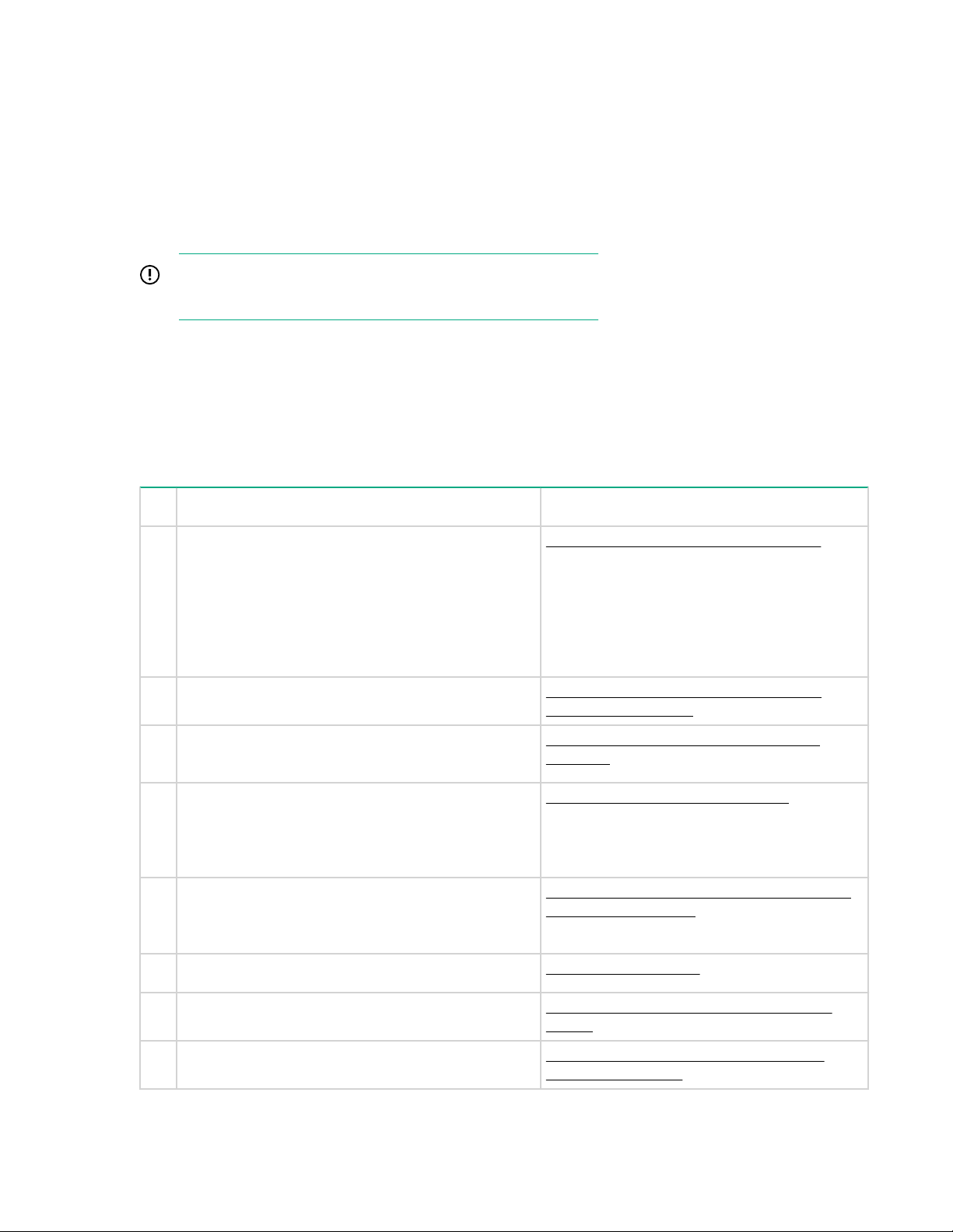
Figure 1: Cabling between server, PCIe slot 2, and bundled enclosure
From To
Drawer 2, I/O module A, port 1 Drawer 1, I/O module A, port 2
Drawer 2, I/O module B, port 1 Drawer 1, I/O module B, port 2
RAID card in PCI slot 2, port 1 Drawer 1, I/O module A, port 1
RAID card in PCI slot 2, port 2 Drawer 2, I/O module B, port 2
SAS cable lengths for HPE StoreOnce Systems
The StoreOnce implementation uses Managed Cables, making it easier to identify faults. The StoreOnce
software verifies that the correct length SAS cables are being used. Mini-SAS HD connectors are used
throughout.
SAS cables ‘click’ and lock into position when correctly inserted. Three cable lengths are available. The
maximum supported cable length is 2.0 m.
SAS cable lengths for HPE StoreOnce Systems 13
Page 14
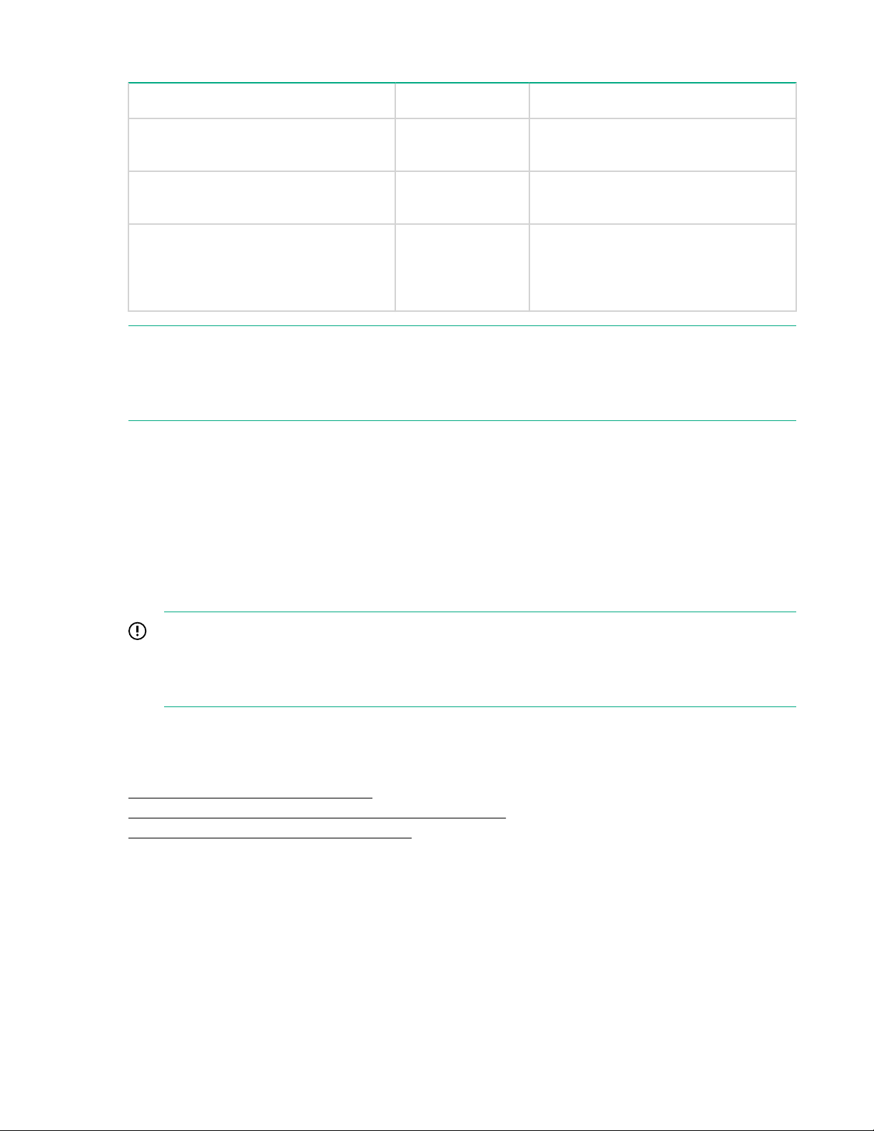
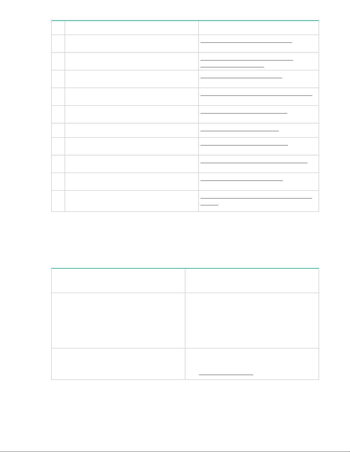
Table 7: Supported SAS cables
Description Part Number Location for use
0.5 m Mini-HD SAS to Mini-HD SAS
cable
1.0 m Mini-HD SAS to Mini-HD SAS
cable
2.0 m Mini-HD SAS to Mini-HD SAS
cable
NOTE:
To facilitate future expansion, HPE recommends using 2.0 m SAS cables to connect from the server to
Drawer 2 of the disk enclosure. For this reason, the base system of one server and one disk enclosure is
supplied with two 0.5 m cables and two 2.0 m cables.
691970-001 Between drawers of a disk enclosure
691970-002 Between disk enclosures or between
691970-003 Between the server and the disk
Expansion installation scenarios
Two installation scenarios are recommended for customers who self-install the HPE StoreOnce 5500
System into their own racks. These scenarios are fully documented in the HPE StoreOnce 5500 System
Capacity Upgrade Guide.
the server and the disk enclosure
enclosure if the 1.0 m cable is not long
enough. Do not use to connect one disk
enclosure to another.
• Two enclosures above and two enclosures below the head server
• Four enclosures below the server.
IMPORTANT:
The HPE StoreOnce 5500 System uses HPE Managed cables. If you choose not to follow one of
the recommended configurations, your system may experience errors with the StoreOnce SAS
check function that checks SAS cable integrity.
Refer to the HPE StoreOnce 5500 System Capacity Upgrade Guide for detailed step-by-step cabling
instructions. Guidelines are as follows.
More information
Up to four enclosures below the server on page 16
Two enclosures above and two enclosures below the server on page 15
Factory-integrated SAS cabling configuration on page 18
Connecting enclosures
Procedure
1. Connect the first enclosure to the RAID controller card in slot 2 of the server.
2. Connect the second enclosure to the RAID controller card in slot 3 of the server.
14 Expansion installation scenarios
Page 15
3. Daisy chain the third enclosure to the first enclosure.
4. Daisy chain the fourth enclosure to the second enclosure.
WARNING:
Never disconnect all SAS cabling at the same time while the system is powered on. It is essential to
maintain an active SAS connection throughout the expansion process.
Daisy chaining enclosures
Procedure
1. Connect the interlink cables between the two drawers in the new enclosure.
2. Connect the IOM A modules in the two enclosures.
3. Make the connection from the P2 of the RAID controller to the newly added enclosure.
IMPORTANT:
Do not disturb the SAS cabling between P1 of the RAID controller card and the existing
enclosure.
4. Connect the IOM B modules in the two enclosures.
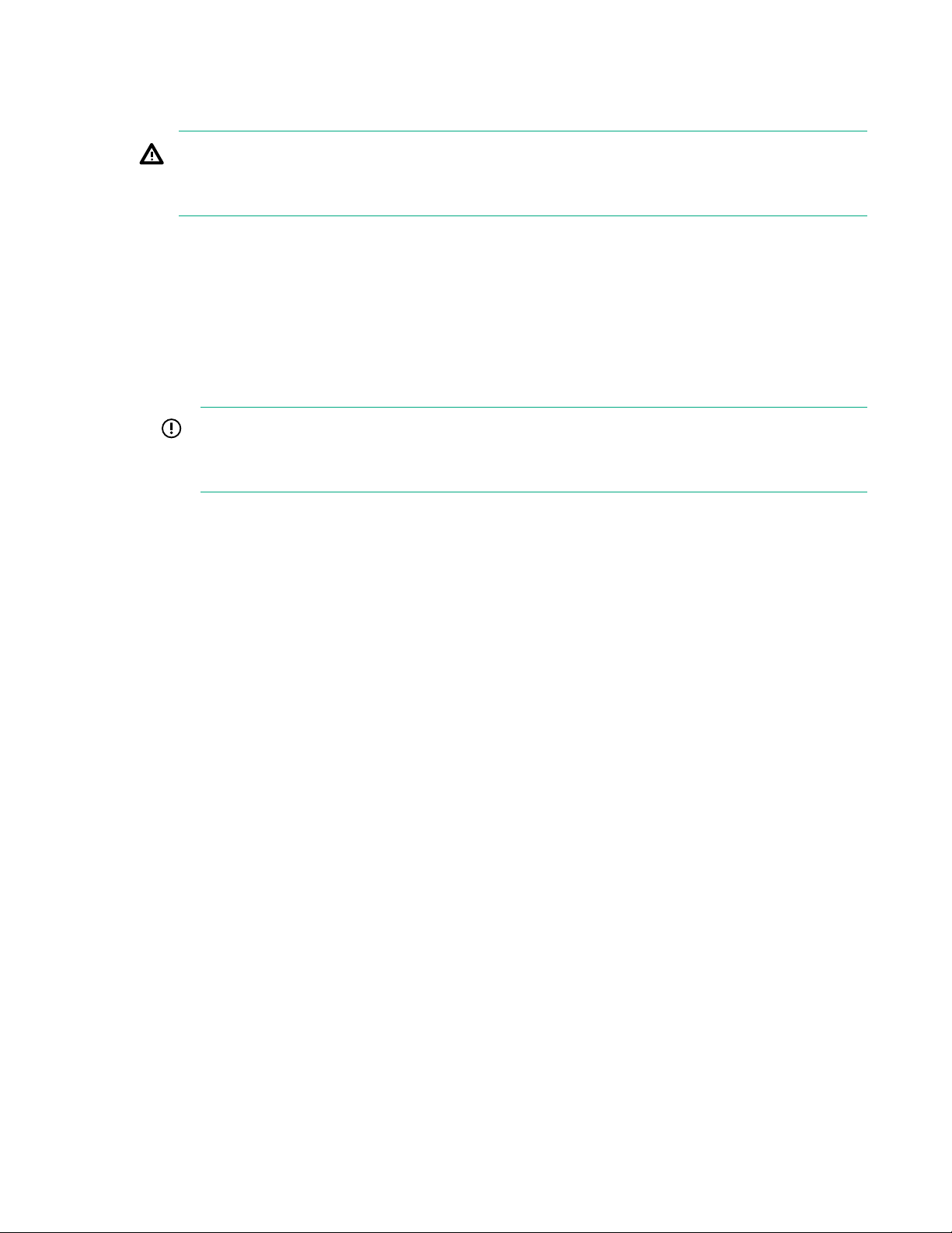
Two enclosures above and two enclosures below the server
The following diagram illustrates the cabling for all four enclosures where two enclosures are above and
two enclosures are below the server. This configuration provides equal weight distribution in the rack. To
provide protection from the weight of the disk enclosures, the 1U support shelf is installed immediately
above the server. Refer to the HPE StoreOnce 5500 System Capacity Upgrade Guide for detailed stepby-step cabling instructions.
Daisy chaining enclosures 15
Page 16
1
2
3
4
1
5
6
4
4
1
iLO
PS2
PS1
#1
#4
#2
#3
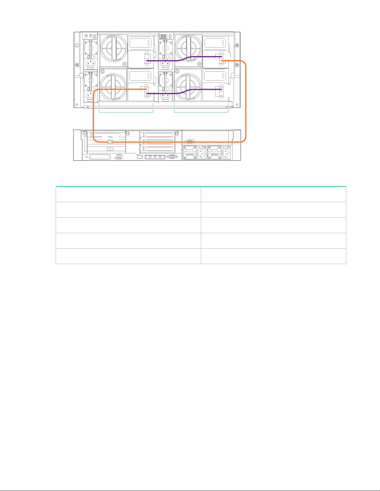
Figure 2: Cabling showing two enclosures above and two enclosures below the server
NOTE:
Enclosure #1 and Enclosure #3 are in Storage Cluster 1, connected to the RAID controller card in slot 2.
Enclosure #2 and Enclosure #4 are in Storage Cluster 2, connected to the RAID controller card in slot 3.
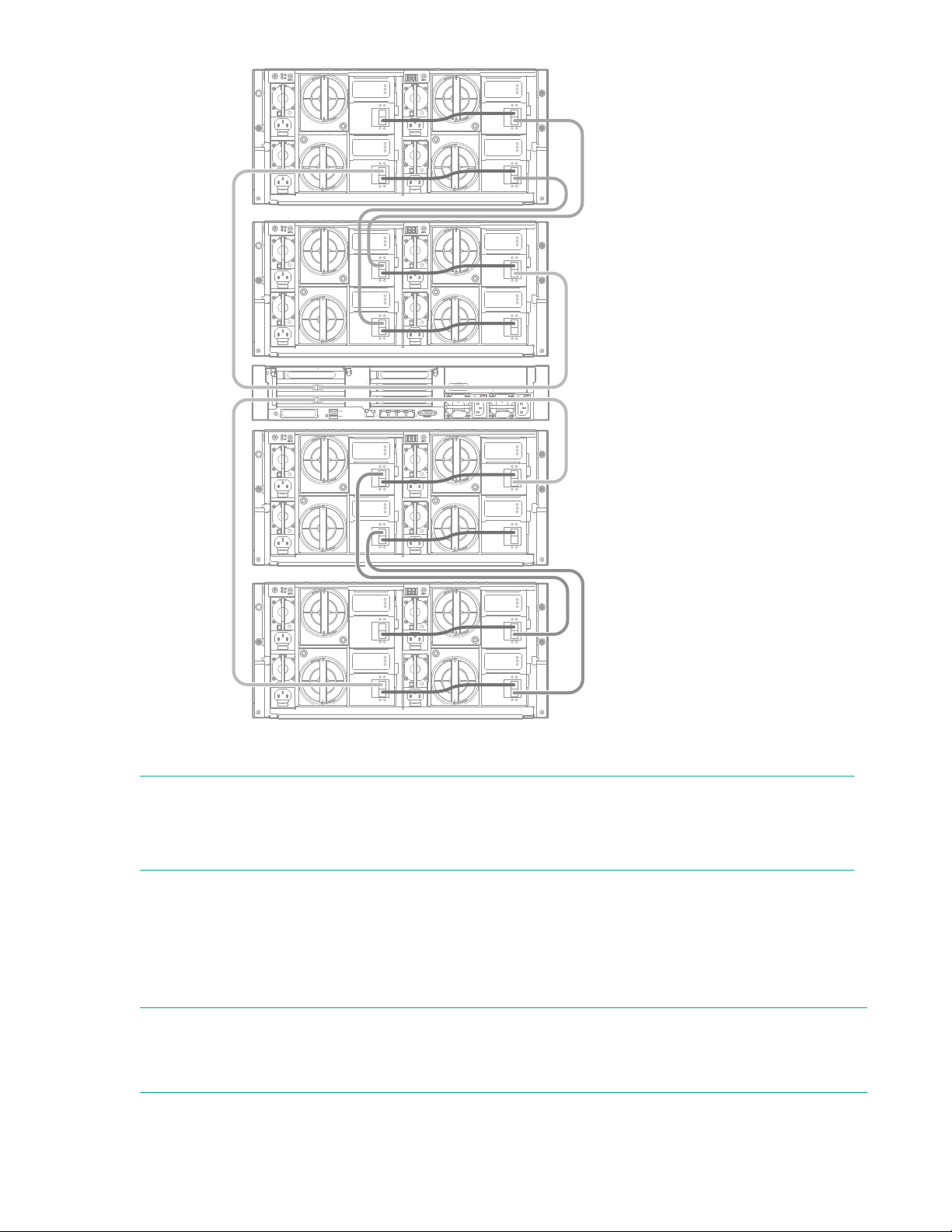
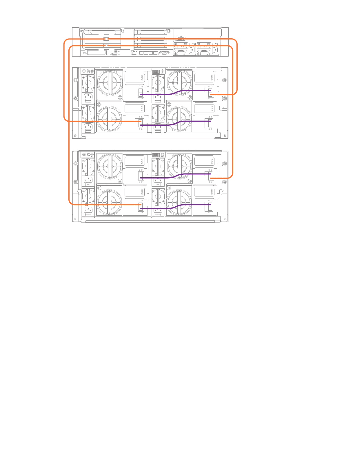
Up to four enclosures below the server
The second recommended configuration has the server at the top and all enclosures below it. It requires
one 1U support shelf, which should be installed below the last enclosure. This configuration provides
easier access to the server when cabling multiple enclosures. There is a 1U support shelf underneath the
lowest disk enclosure.
NOTE:
If you choose not to follow one of the recommended configurations, your system may experience errors
with the StoreOnce SAS check function that checks SAS cable integrity.
16 Up to four enclosures below the server
Page 17
1
2
3
4
1
5
6
4
4
1
iLO
PS2
PS1
IOM A
IOM B
IOM A
IOM B
IOM A
IOM B
IOM A
IOM B
P2
P1
P2
P1
P2
P1
P2
P1
P2
P1
P2
P1
P2
P1
P2
P1
P1P2
P1P2
#2
#1
Figure 3: Cabling showing two enclosures installed below the server
SAS cabling for HPE StoreOnce 5500 Systems 17
Page 18

1
2
3
4
1
5
6
4
4
1
iLO
PS2
PS1
IOM A
IOM B
IOM A
IOM B
IOM A
IOM B
IOM A
IOM B
P2
P1
P2
P1
P2
P1
P2
P1
P2
P1
P2
P1
P2
P1
P2
P1
IOM A
IOM B
IOM A
IOM B
IOM A
IOM B
IOM A
IOM B
P2
P1
P2
P1
P2
P1
P2
P1
P2
P1
P2
P1
P2
P1
P2
P1
P1P2
P1P2
#2
#3
#4
#1
Figure 4: Cabling showing four enclosures installed below the server
NOTE:
Enclosure #1 and Enclosure #3 are in Storage Cluster 1, connected to the RAID controller card in slot 2.
Enclosure #2 and Enclosure #4 are in Storage Cluster 2, connected to the RAID controller card in slot 3.
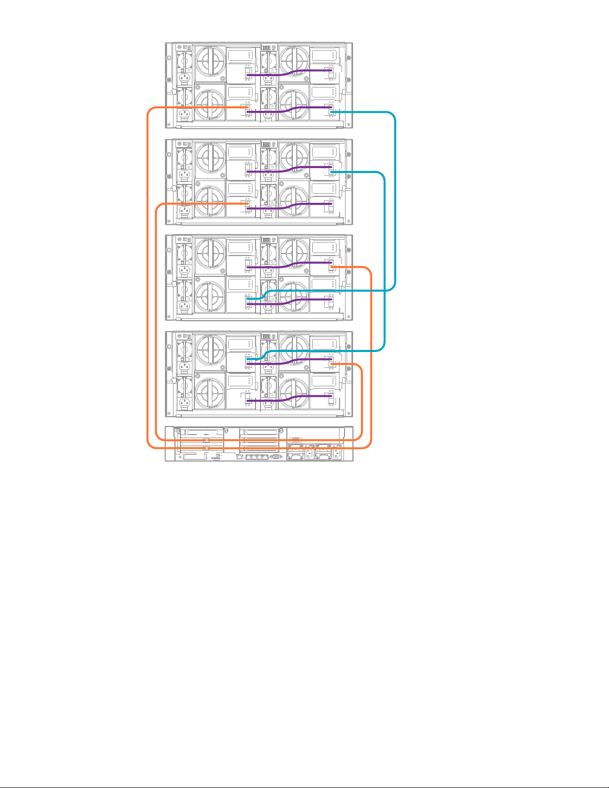
Factory-integrated SAS cabling configuration
There is a third option, the factory-integrated option, where the customer orders a system that is prebuilt
by HPE into a rack. This installation has specific shipping requirements to keep the mass of the rack as
low as possible while in transit. The server is at the lowest level and the four enclosures are installed
above the server. The 1U shelf is located above the server to protect it from the weight of the disk
enclosures. HPE does not anticipate the customer altering the layout of the factory–integrated option.
If neither of the recommended options are feasible, the factory-integrated option is also a viable option for
self-installing customers. Contact HPE Support for cabling details, if necessary.
18 Factory-integrated SAS cabling configuration
Page 19
1
2
3
4
1
5
6
4
4
1
iLO
PS2
PS1
IOM A
IOM B
IOM A
IOM B
IOM A
IOM B
IOM A
IOM B
P2
P1
P2
P1
P2
P1
P2
P1
P2
P1
P2
P1
P2
P1
P2
P1
IOM A
IOM B
IOM A
IOM B
IOM A
IOM B
IOM A
IOM B
P2
P1
P2
P1
P2
P1
P2
P1
P2
P1
P2
P1
P2
P1
P2
P1
P1P2
P1P2
#3
#2
#1
#4
Figure 5: SAS cabling on factory-integrated systems
SAS cabling for HPE StoreOnce 5500 Systems 19
Page 20

Powering up and setting up iLO4
Powering up the HPE StoreOnce 5500 System
If the StoreOnce system has not yet been powered on, as described in the appropriate Start Here poster,
or if you need to configure iLO 4 from a direct connection, perform the following steps.
Procedure
1. Perform a final check to ensure all cables are connected correctly and securely:
2. Server unit
a. Two power cables to the server
b. Keyboard and monitor cables
c. Network cable to LAN port 1
d. Network cable to iLO port
e. Optional hardware — see the StoreOnce Optional Hardware Installation and Configuration Guide
3. Disk enclosure(s)
a. Four power cables to the disk enclosure
b. Two 2 m SAS cables from the disk enclosure to the first RAID controller card (slot 2)
c. Two 0.5 m SAS cables between the drawers on the disk enclosure
NOTE:
See Hardware overview reference section on page 68 for cabling examples.
4. Power on all installed disk enclosures first. You may need to hold down the power on button (1) on the
rear of each unit for up to 30 seconds. Look at the LEDs on the I/O modules and wait until the Green
Status LED (3) remains on, and the Locate LED (2) and the Fault LED (4) are both off.
20 Powering up and setting up iLO4
Page 21
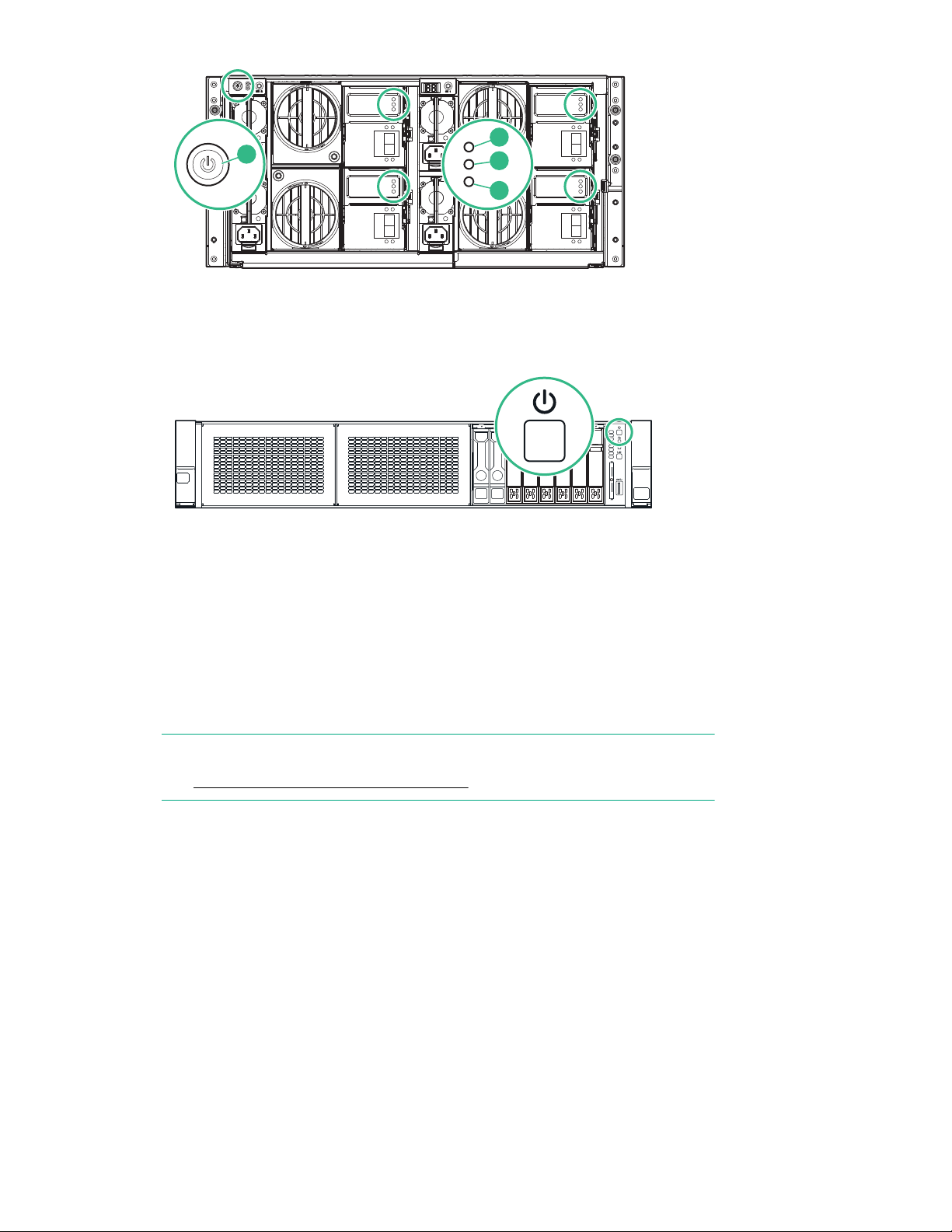
2
1
3
4
5. Power on the HPE StoreOnce 5500 System (the power button is on the front of the unit). The Power
SID
1 2 3 4 5 6 7 8
button LED flashes green during the power-on sequence, and the Power button, System Health and
NIC status LEDs all show steady green when the StoreOnce System is powering up.
Powering up StoreOnce 3100, 3500 and 5100 Systems
If the StoreOnce system has not yet been powered on, as described in the appropriate Start Here poster,
or if you need to configure iLO 4 from a direct connection, perform the following steps.
Procedure
1. Perform a final check to ensure all cables are connected correctly and securely:
NOTE:
See Hardware overview reference section on page 68 for cabling examples.
• Power cable(s)
• Keyboard and monitor cables
• Network cable to LAN port 1
• Network cable to iLO port
• Optional hardware, StoreOnce 3500 Series and StoreOnce 5100 System
• Capacity Upgrade Kits, StoreOnce 5100 System only
2. HPE StoreOnce 5100 System only: If an expansion enclosure has been installed, power on the
enclosure first.
Powering up StoreOnce 3100, 3500 and 5100 Systems 21
Page 22
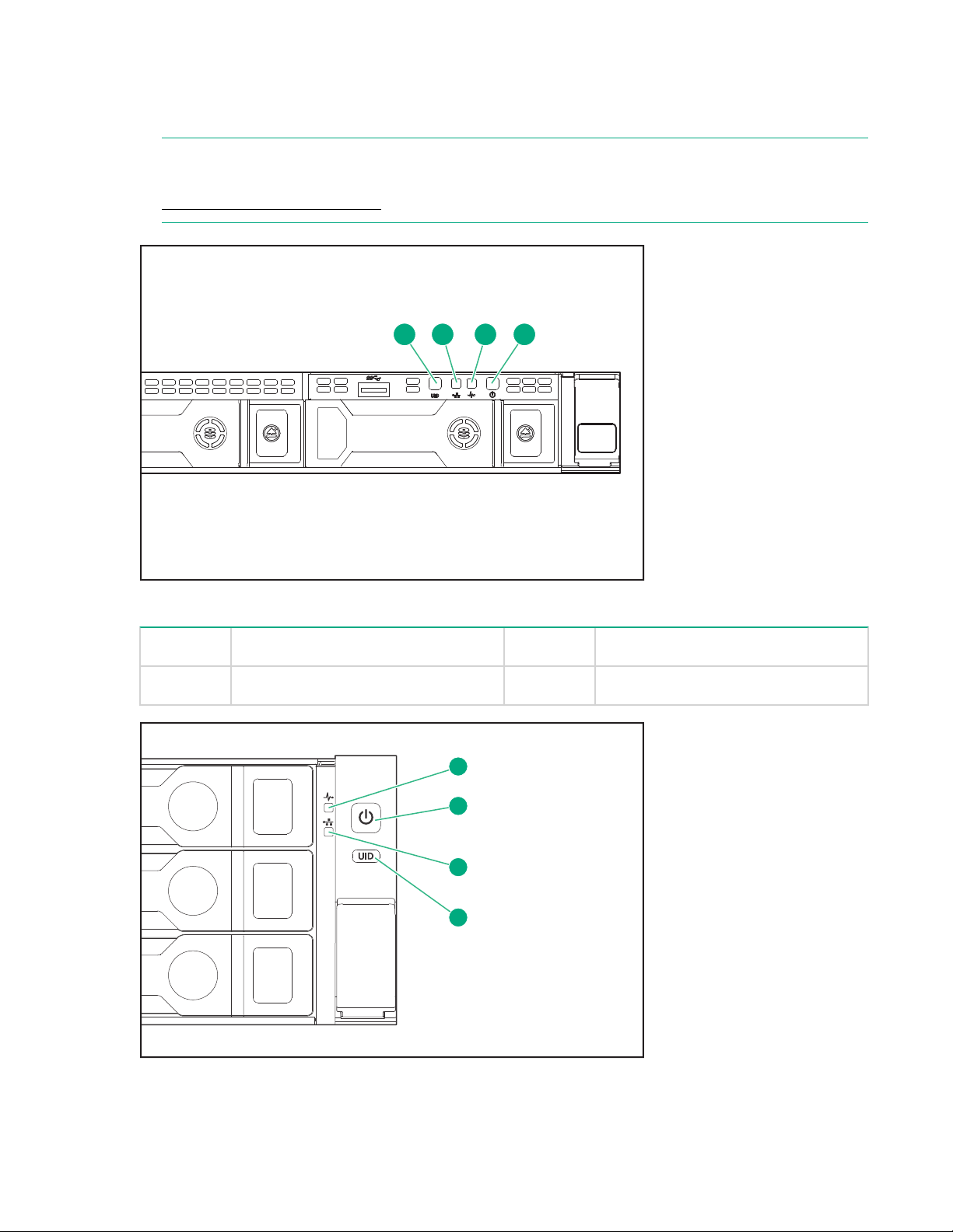
3. Power on the StoreOnce System (the power button is on the front of the unit).
3 4
1 2 3 4
1
2
3
4
4. The Power button LED flashes green during the power-on sequence, and the Power button, System
Health and NIC status LEDs all show steady green when the StoreOnce System is powering up.
NOTE:
If you wish to configure iLO 4, press F9 in the ProLiant POST screen and proceed as described in
Configuring iLO4, all systems on page 23 .
Figure 6: Powering up HPE StoreOnce 3100 System
1 UID LED 2 NIC status LED
3 System health LED 4 Power LED and on/off button
Figure 7: Powering up HPE StoreOnce 3500 Series and 5100 System
22 Powering up and setting up iLO4
Page 23

1 System health LED 2 Power LED and on/off button
3 NIC status LED 4 UID LED
iLO network name and iLO password
StoreOnce Systems are built on ProLiant server hardware and use the embedded Integrated Lights-Out 4
(iLO 4) management technology. iLO enables secure remote monitoring and console access via a web
browser.
iLO is not required for daily management of the StoreOnce appliance but is useful in a lights-out data
center situation. iLO is also useful for diagnosing hardware failures that prevent access to the appliance
through the primary StoreOnce GUI or remote StoreOnce CLI interface.
All StoreOnce Systems described in this guide are supplied with a label that includes the iLO network
name and iLO password. Ideally, the installer has made a note of this information, as recommended in
Step 3 of the printed Start Here guide. If not, it will be necessary to locate the label on the top of the
appliance in the data center.
It is good practice to either change the password after installation, or define an additional user with
privileges that can be used when accessing iLO from a web browser.
Configuring iLO4, all systems
Procedure
1. Boot up the StoreOnce System and watch the local console; the iLO4 IP addresses are shown (IPv4
and IPv6).
NOTE:
If the iLO port is plugged into a network that provides DHCP, the acquired addresses will be shown
here and you can connect to the network address in a web browser in order to configure iLO.
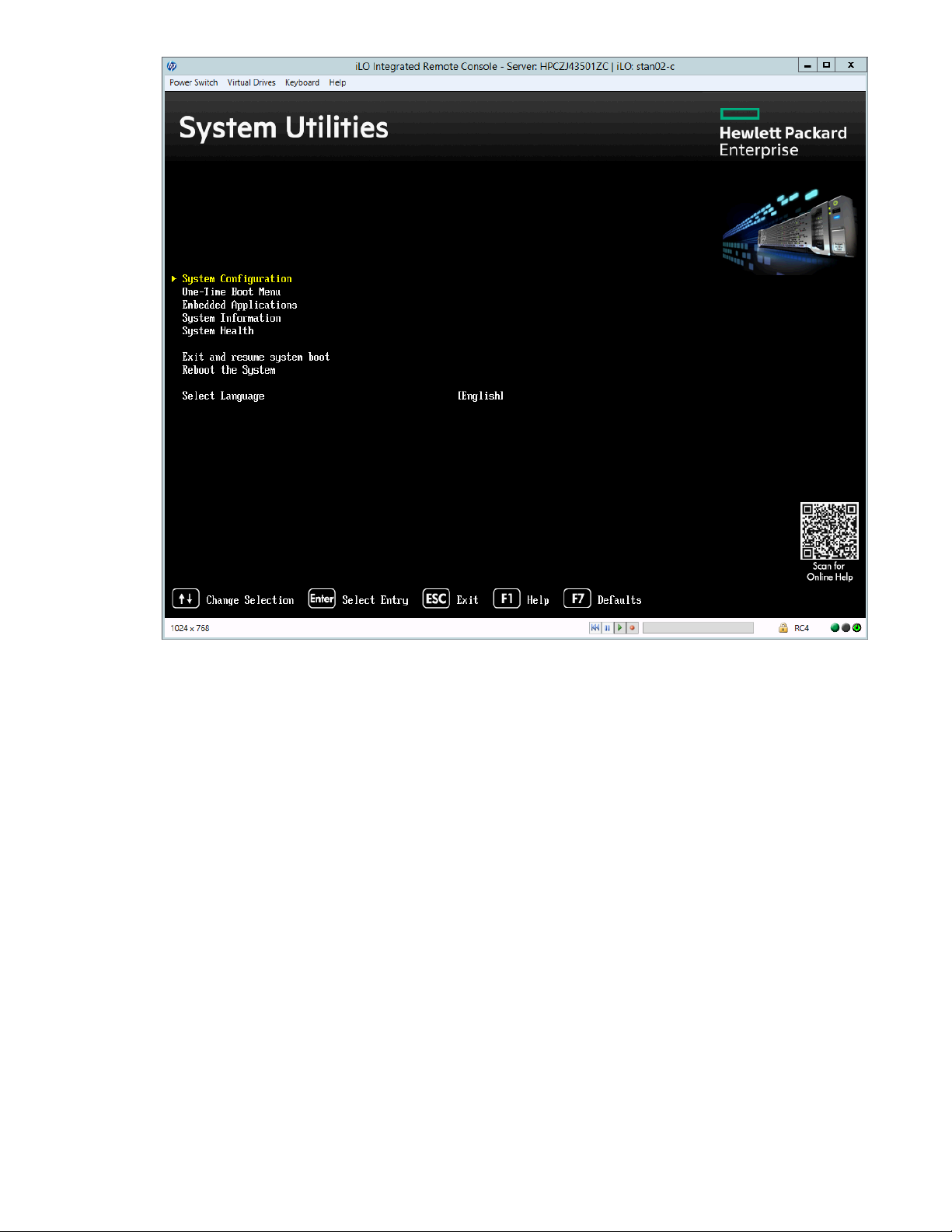
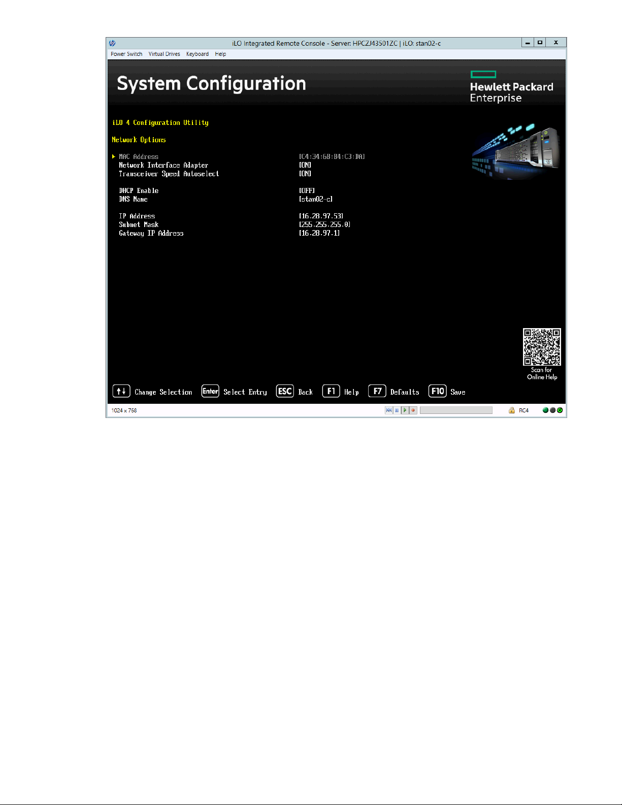
2. If there are no DHCP–assigned IP addresses, you can manually configure iLO using the local console.
Press F9 in the ProLiant POST screen to access System Utilities. Select System Configuration.
iLO network name and iLO password 23
Page 24
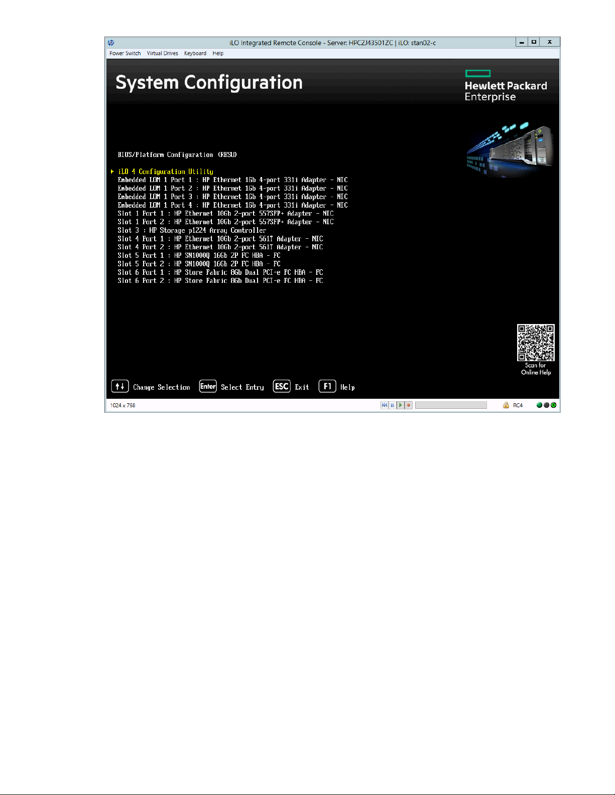
3. Select the iLO 4 Configuration Utility.
24 Powering up and setting up iLO4
Page 25
4. Select Network Options.
Powering up and setting up iLO4 25
Page 26

5. Configure your network settings and press F10 to save.
26 Powering up and setting up iLO4
Page 27
6. Then exit. The system will continue to boot normally into the StoreOnce OS.
Basic network configuration
If you have not already done so, run the basic network script net set address as described in the
Start Here poster for your product, to configure a static address for LAN port 1 (eth0). Make a note of the
IP address details, which you will need to log into the StoreOnce System from a web browser.
Basic network configuration 27
Page 28

Logging in to the HPE StoreOnce System and checking status
More information
Configuring licenses on page 34
The StoreOnce login banner on page 29
Supported web browsers
The StoreOnce Management GUI is supported on the following web browsers:
• Internet Explorer 9, 10 and 11 (note that Internet Explorer 8 is not supported and some StoreOnce
features will not work)
• Mozilla Firefox v23 and above and Firefox ESR24 and above.
IMPORTANT:
The web browser used to communicate with the StoreOnce System requires Active Scripting or
JavaScript enabled. Without these scripts enabled, some browser buttons will not display.
Logging in to the HPE StoreOnce System and checking status
To log on to the StoreOnce Management GUI, use any machine connected to the same network as the
appliance. The StoreOnce System uses a secure network connection.
Procedure
1. Enter: https://<IP_address>.
2. You may also use the Fully Qualified Domain Name (FQDN).
NOTE:
If you use http: in the URL, you are automatically forwarded to the https: secure network connection.
3. The StoreOnce Management Console displays the Login prompt. Provide the default User Name and
Password (Admin, admin). You can also set the local language to display the text within the
StoreOnce GUI from the Login screen.
4. The HPE StoreOnce Configuration Wizard is automatically displayed. You can either work through the
recommended configuration tasks or click Discard.
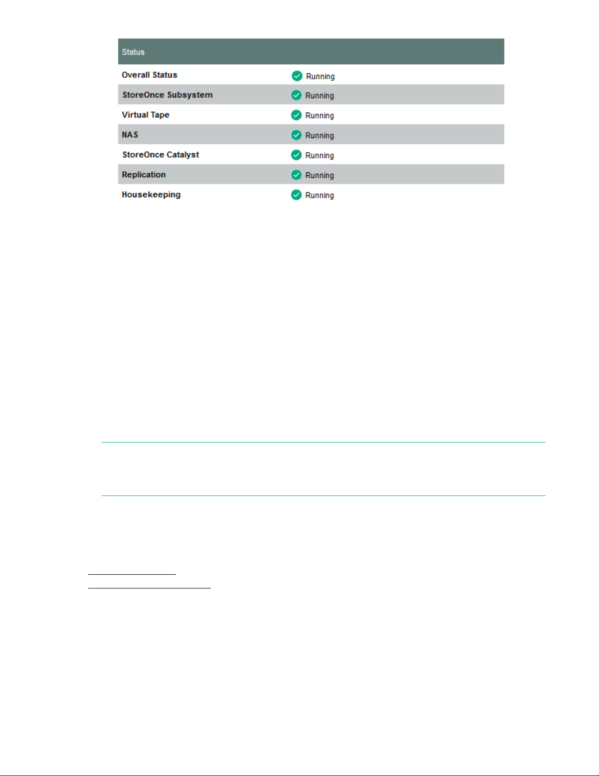
5. Look at the following pages to verify status information:
a. StoreOnce to check the overall status and the status of all services. They should all display with a
green √ and Running.
28 Logging in to the HPE StoreOnce System and checking status
Page 29
b. Device Configuration — License Management to see what licenses have been applied. This
page will also identify any Capacity Upgrade Kits and Optional Hardware that has been installed
and licensed.
Accessing the StoreOnce CLI
The examples in this guide illustrate how to use the StoreOnce GUI to carry out configuration tasks.
However, all tasks may also be performed from the StoreOnce CLI, as described in the HPE StoreOnce
System CLI Reference Guide.
Procedure
1. StoreOnce CLI commands require an SSH client application (freely available from the internet) and
must be run from a SSH terminal session on a machine that is on the same network as the StoreOnce
appliance:
ssh <username>@<ip_address>
NOTE:
StoreOnce CLI commands can also be run from a local console (Keyboard and Monitor) attached to
the appliance, for example, if the network is not yet configured.
2. At the prompts provide a User Name and Password (Admin, admin).
3. See the StoreOnce System CLI Reference Guide for more information.
More information
Configuring licenses on page 34
The StoreOnce login banner on page 29
The StoreOnce login banner
The login banner is displayed whenever users log in, either to the StoreOnce CLI or through the
StoreOnce GUI. It consists of blocks of text that may provide legal or other conditions that apply to users
of the device.
Banner text strings must conform to the following conditions:
Accessing the StoreOnce CLI 29
Page 30

1. Banner text must be ASCII text – in particular, wider Unicode text is not permitted.
2. Banner text length must be less than or equal to 10,240 characters.
3. Banner text must not contain the backslash character “\”.
Banner text that does not conform to the conditions will be rejected. No processing or formatting of the
text is carried out either at creation or during display.
Setting up a login banner
Procedure
1. Create a file containing the login text content and save it as a .txt file, for
example:login_banner.txt
2. Use sftp to copy the text file to the repository folder of the StoreOnce appliance.
3. Log in to the StoreOnce CLI.
4. Run the StoreOnce CLI command with the appropriate text file name to apply the banner:
$ system set banner login_banner.txt
5. Exit the StoreOnce CLI.
• When you log back into the StoreOnce CLI, the banner text will displayed after you enter your user
name and before you enter your password.
• When you log in to the StoreOnce GUI, the login banner will be displayed on the Welcome page.
You must click OK before you can enter your user name and password.
30 Setting up a login banner
Page 31

Configuring Remote Support
StoreOnce Remote Support
Remote support is available with supported devices as part of your warranty or contractual support
agreement. It provides intelligent event diagnosis, and automatic, secure submission of hardware event
notifications to Hewlett Packard Enterprise, which will initiate a faster and more accurate resolution of any
issues based on your product’s service level. Hewlett Packard Enterprise strongly recommends that you
register your device for remote support.
The preferred HPE Remote Support solution for StoreOnce products is Service Tools and Technical
Support (STaTS), however Insight Remote Support is also available.
Remote Support via STaTS is a standard StoreOnce feature that is enabled and available to all users. It
monitors your system and allows the system to proactively contact Hewlett Packard Enterprise if issues
arise on the system.
If you do not configure Remote Support via STaTS, you will be prompted to do so every time you log onto
the StoreOnce Management GUI. To prevent this, you should go to the Remote Support pages on the
StoreOnce Management GUI and either configure it, or select No Support, as appropriate.
NOTE:
The following example is generic; it is not intended to be product specific, merely to illustrate the overall
procedure.
For information about using specific GUI pages to configure Remote Support, see the appropriate
sections in the StoreOnce System user guide. The sections in the User Guide also contain example
screenshots.
Setting up Remote Support on the StoreOnce Management GUI
Procedure
1. Go to the Remote Support pages of the StoreOnce Management GUI.
2. Click Modify. Most fields have default values that do not need to be edited. However, you must
provide the details for the proxy server that enables internet access for Remote Support. If required for
the network environment, check the Enable Authentication box and provide authentication name and
password details. Click OK.
NOTE:
Details for the Enterprise Server(the server that will receive the event messages) are provided by the
StoreOnce System and should not be edited.
3. Select Customer Information. Click Modify and enter technical contact details for the customer site.
It is important to fill in the information on this page because HPE Support will use it to provide
feedback and instructions on resolving any issues. Information is required for all fields marked with an
asterisk.
4. Select Entitlement. The system will extract the warranty serial information from the BIOS. Warranty
serial number information present in the BIOS cannot be modified.
Configuring Remote Support 31
Page 32

5. Click Send Test Event on the Remote Support page and use the Events page to verify that the test
event was sent.
6. Contact HPE Support and ask to verify a remote support event has been received.
7. The HPE Support person will check on the database portal that the event has been received and will
also verify that warranty/serial/part numbers are valid and under warranty (or have valid care packs).
8. This completes Remote Support via STaTS verification.
More about warranty details
• StoreOnce 3100 and 3500 Systems: These systems have a single entry. The warranty serial number
covers both the server and the embedded disks.
• StoreOnce 5100 Systems: These systems have a separate entry for the server, where the warranty
serial number covers both the server and the embedded disks.
If additional storage enclosures have been installed, there will be a separate entry for each enclosure,
and each entry will have a unique warranty serial number. (The warranty product number is identical
for each enclosure.)
• StoreOnce 5500 Systems: These systems have a separate entry for the server, where the warranty
serial number covers both the server and the base storage.
If additional disk packs have been installed, there will be a separate entry for each disk pack. This is
for information only; disk packs do not carry warranty details (the warranty columns will show Not
Applicable).
If an additional disk enclosure has been installed, it will have a separate entry with a unique warranty
serial number. (Additional disk packs installed in the additional enclosure are displayed without the
warranty serial number or the warranty part number and this is a non-editable field.)
32 More about warranty details
Page 33

HPE StoreOnce Configuration Wizard
Purpose of the HPE StoreOnce Configuration Wizard
When deploying or upgrading to StoreOnce version 3.16.0 or later, the first time a user logs in to the
StoreOnce GUI, the user must select whether to configure Remote Support or No Support. Once this
selection is made, the HPE StoreOnce Configuration Wizard is automatically displayed.
The wizard guides you through the system's first-time installation of:
• Time and date
• User management
• License management
• Optional hardware
• Network configuration
• Storage
• Email configuration
Using the StoreOnce Configuration Wizard
If you do not want to follow the steps in the wizard, click Discard.
Procedure
1. Click Proceed to display the recommended configuration steps and sequence.
2. Click the link to the first step.
3. Make the required changes and click Finish to return to the wizard.
4. Continue to work through the tasks shown in the wizard. Refer to either the online help or the
appropriate chapter in this guide for more information about individual tasks. Check the Advanced box
to display additional, optional configuration tasks.
5. You may leave the configuration wizard at any time by clicking Exit. The system gives you the option
of creating StoreOnce backup targets. Either click on one of the links or click OK to finish.
6. To redisplay the wizard, select Configuration Wizard from the Navigator.
7. The wizard displays every time you log on. To prevent this happening, check the Do not show at next
login box.
HPE StoreOnce Configuration Wizard 33
Page 34

Configuring licenses
Licensing is required for a number of StoreOnce functions or hardware features.
Capacity expansion license for StoreOnce 5500
This is storage that is additional to the base product. Each Capacity Upgrade after installation requires a
license that must be loaded.
The HPE StoreOnce 5500 System supports two capacity expansion options.
• BB941A: HPE StoreOnce 5500 System Capacity Upgrade Disk Pack
The HPE StoreOnce 5500 System (44 TB) Capacity Expansion kit is a pack of eleven 4 TB disks,
which are added to the original disk enclosure in the sequence described in this guide. A maximum of
five of these kits may be used with the first enclosure until all disk bays are full.
• BB933A: HPE StoreOnce 5500 System Capacity Upgrade Enclosure with Disks
Once all bays in the disk enclosure are full, it is possible to connect three further Capacity Upgrade
Kits to your HPE StoreOnce 5500 System. These are 60 TB disk enclosures. Care must be taken to
ensure the integrity of the SAS cabling when connecting additional enclosures.
Storage in each enclosure may also be expanded using up to five of the BB941A expansion kits.
For additional information, see the HPE StoreOnce 5500 System Capacity Upgrade Guide.
Pre-installed Capacity licenses
If capacity expansion has been ordered and pre-configured by the factory with the base system, the
license will already have been applied.
Note that Manufacturing will use a single license that covers all expansions. For example, a fully
populated HPE StoreOnce 5500 System with five Capacity Upgrade disk packs will display a 1 x 44 TB
license that covers 220 TB on the License Management page.
This facility to bundle multiple 44 TB Capacity Upgrade licenses is not available to the customer after
installation.
Capacity expansion license for HPE StoreOnce 3500 Series and HPE StoreOnce 5100 System
The HPE StoreOnce 3100 System has 4 x 2 TB disks and does not support capacity expansion.
• The HPE StoreOnce 3500 Series is supplied with 12 disks; two models are available, HPE StoreOnce
3540 System (12 x 4 TB disks) and HPE StoreOnce 3520 System( 12 x 2 TB disks). The base
configuration for both models uses 50% of the available capacity (24 TB or 12 TB). Capacity
expansion is available by purchasing and applying a license for the remaining disk capacity. Neither
model supports additional storage disk packs or enclosures.
If configured in the factory for the full capacity of 48 TB (3540 model) or 24 TB (3520 model), all
storage will already be licensed. If not factory configured, the license entitlement will be delivered to
the user via email. See also Expanding storage capacity, if supported on page 50 .
• The HPE StoreOnce 5100 System supports capacity expansion; up to five Capacity Upgrade Kits,
BB916A, may be connected to the base system and each requires a license. If configured in the
34 Configuring licenses
Page 35

factory for capacity expansion, all storage will already be licensed and available for use. If not factory
configured, the license entitlement will be delivered to the user via email and the storage must be
added to the RAID configuration. See the StoreOnce 5100 48 TB Capacity Upgrade Kit Guide for
further information.
Each Capacity Upgrade after installation requires a license that must be loaded.
NOTE:
If capacity expansion has been ordered and pre-configured by the factory with the base system, the
license will already have been applied.
Security license
Security: Security features (Data at Rest Encryption, Data in Flight Encryption, and Secure Erase)
require a Security license.
NOTE:
Data in flight encryption is intended to be used to secure links between data centers for StoreOnce VTL
or NAS Replication or Low Bandwidth Catalyst Copy operations. Using Data In Flight Encryption for direct
backup operations to the StoreOnce appliance over a local network is not supported due to the
performance impact of the encryption.
Target devices and Catalyst stores licenses
• StoreOnce Catalyst:
StoreOnce Catalyst devices require a license for backup and for copy, so licenses must be installed on
both origin and destination HPE StoreOnce Systems.
• Replication:
VTL and NAS replication requires a license on the target system. There is no licensing requirement for
backup to VTL or NAS share devices.
StoreOnce Optional Hardware licenses
StoreOnce Optional Hardware kits contain additional 10 GbE Network or Fibre Channel cards that may
be installed in the PCIe slots on the HPE StoreOnce 5500 System, HPE StoreOnce 3500 Series and the
HPE StoreOnce 5100 System. Each additional FC or 10 GbE card must be licensed. See Optional PCIe
cards on page 76 for more details.
NOTE:
The StoreOnce 3100 does not support optional PCIe cards.
Security license 35
Page 36

Checking for installed licenses
Procedure
1. In the Navigator pane, expand Device Configuration and then click on License Management. This
page details of any licenses that have been already installed.
2. Go to the appropriate section.
3. The following example shows an HPE StoreOnce 5100 System which has been factory-licensed for a
fully-expanded storage capacity with five 48TB Capacity Upgrade enclosures.
Applying a demo license
The Instant on or Demo licenses allow you to try out StoreOnce Catalyst and Replication before paying
for and applying the Full licenses. The licenses are time limited to 90 days.
Procedure
1. In the Navigator pane, click on License Management.
2. On the License Management page, click Add License.
36 Checking for installed licenses
Page 37

3. For the Input Type, select Key String.
4. For the License Key, type in the word “demo”.
5. Click OK to apply the license.
StoreOnce full license
Redeeming a license
Before you add a full license, you must redeem the license.
Procedure
1. Make sure you have a note of the Node Lock Serial Number from the License Management page
on the StoreOnce GUI.
2. Go to the HPE Licensing website.
3. Log in using your HP Passport user ID and password.
StoreOnce full license 37
Page 38

4. Obtain the unique LTU key as instructed on the License Entitlement Certificate. You may use Cut and
Paste to copy it to a temporary file or save it to a .DAT file.
If you save the LTU as a file, sftp it into the StoreOnce System’s licenses directory.
IMPORTANT:
If you cut and paste the string, you must remove the product description from the beginning of
the license string before applying the license to the StoreOnce appliance. Some editors display
the product description on a separate line above the license string; others do not have a line
break before the license string starts. An example product description is: #HPE StoreOnce 16Gb
FC card LTU. (There is no requirement to remove the product description that is displayed in
quotes at the end of the string.)
5. Use the StoreOnce GUI to apply the license, as described in the next section.
Applying a full license
Procedure
1. In the Navigator pane, expand Device Configuration and then click License Management.
2. On the License Management page, click Add License.
3. For the Input Type, select Key String.
NOTE:
See the StoreOnce System User Guide for more information about loading licenses from a file. The
file must already be in the StoreOnce System’s repository directory.
4. In the License Key box, type or paste the license string.
5. See the HPE StoreOnce System User Guide for more information about applying licenses from a
DAT file.
6. Click OK to apply the license and click OK at the license added successfully prompt.
If the license fails, a dialog box will appear that shows error details. Click OK to return to the License
Management page.
NOTE:
For users who prefer to use the StoreOnce CLI, all licenses can be loaded with the single StoreOnce
CLI command license load. This command will load all licenses found in the licenses directory.
See the StoreOnce CLI Reference Guide for more information.
38 Applying a full license
Page 39

Setting time zone and configuring NTP server
Using the StoreOnce GUI to set the time zone
There is not a default time zone set for the StoreOnce appliance.
Procedure
1. In the Navigator, select Time and Date.
2. In Time zone setting, select your desired region from the Select Region drop down. The list will
contain a list of continents to choose from. Select the continent/region in which the StoreOnce
appliance is located.
3. In Select Country, select the country where the StoreOnce appliance is located.
4. In Select Time Zone, select the appropriate time zone within the country you have chosen.
5. In the header for the Time zone setting section of the GUI, click Apply.
6. An Apply Time Zone settings dialog will appear. Select Yes to apply your changes. Select No to
delete your settings.
7. A Time Zone setting success dialog box will appear. Click OK.
NOTE:
The Date Settings portion of the Time and Date page allows you to manually set the date and time of
the appliance.
Using the StoreOnce GUI to configure NTP server
The NTP server configuration provides the option of setting the time and date using one or more NTP
servers. When using the NTP server to configure time and date, manual entry of time and date will be
disabled. You can add up to two NTP server configurations.
Procedure
1. In the Navigator, select Time and Date.
2. In NTP Server Configuration, click the checkbox for NTP Selection Enabled.
3. In the NTP Server Configuration title bar, select Add.
4. In the Add NTP server dialog, enter the following:
a. Select the NTP server type: IPv4, IPv6, or Fully Qualified Domain Name
b. Add the chosen NTP server address into the Address field.
5. Click Add. If the supplied NTP server address is reachable from the StoreOnce appliance, the address
will be added to the NTP configuration and NTP time correction will be enabled.
NOTE:
There is no check that the NTP server is reachable after it is added to the configuration.
Setting time zone and configuring NTP server 39
Page 40

6. In the confirmation dialog box, click OK.
7. If the NTP time is behind the currently configured time on the appliance, you will see a warning dialog
box that reminds you to reboot the system using the system reboot command, and that system
time will move backward as a result of that command.
40 Setting time zone and configuring NTP server
Page 41
Creating user accounts and changing default passwords
StoreOnce user accounts
Two roles define the permissions associated with a user; they are called admin and user. Two default
user accounts, one for each role, are created automatically when the system is installed
• Admin account: This account has permissions associated with an administrator who is responsible for
configuring and managing the HPE StoreOnce System. The default User Name and Password for this
account is Admin, admin.
• User account: This account has operator permissions only and will not be able to carry out any system
configuration; the default User Name and Password for this account is Operator, operator.
Immediately after installation, the administrator should change the default passwords and create
additional user accounts, assigning permissions, as appropriate.
Adding a local user
Procedure
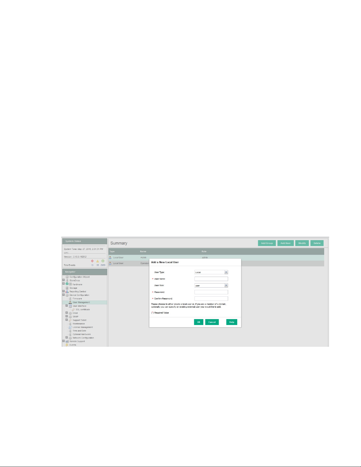
1. Log on as an Administrator and select User Management from the Device Configuration menu.
2. Click Add User.
3. Select a User Type of Local.
Creating user accounts and changing default passwords 41
Page 42
NOTE:
There are two types of users:
• Local Users: A user created solely on the StoreOnce System.
• External Users: A user who belongs to an AD domain to which the StoreOnce System has been
joined. When you add an external user who is already a member of an existing AD group, you have
the ability to assign this user to a different role than the group role. No password is required for the
external user because that is controlled via the AD Domain server. See the StoreOnce System
User Guide for more information about creating and configuring external users.
4. Enter the User Name of the Local User, and select a User Role of user or admin.
5. Click OK.
Changing passwords for local users
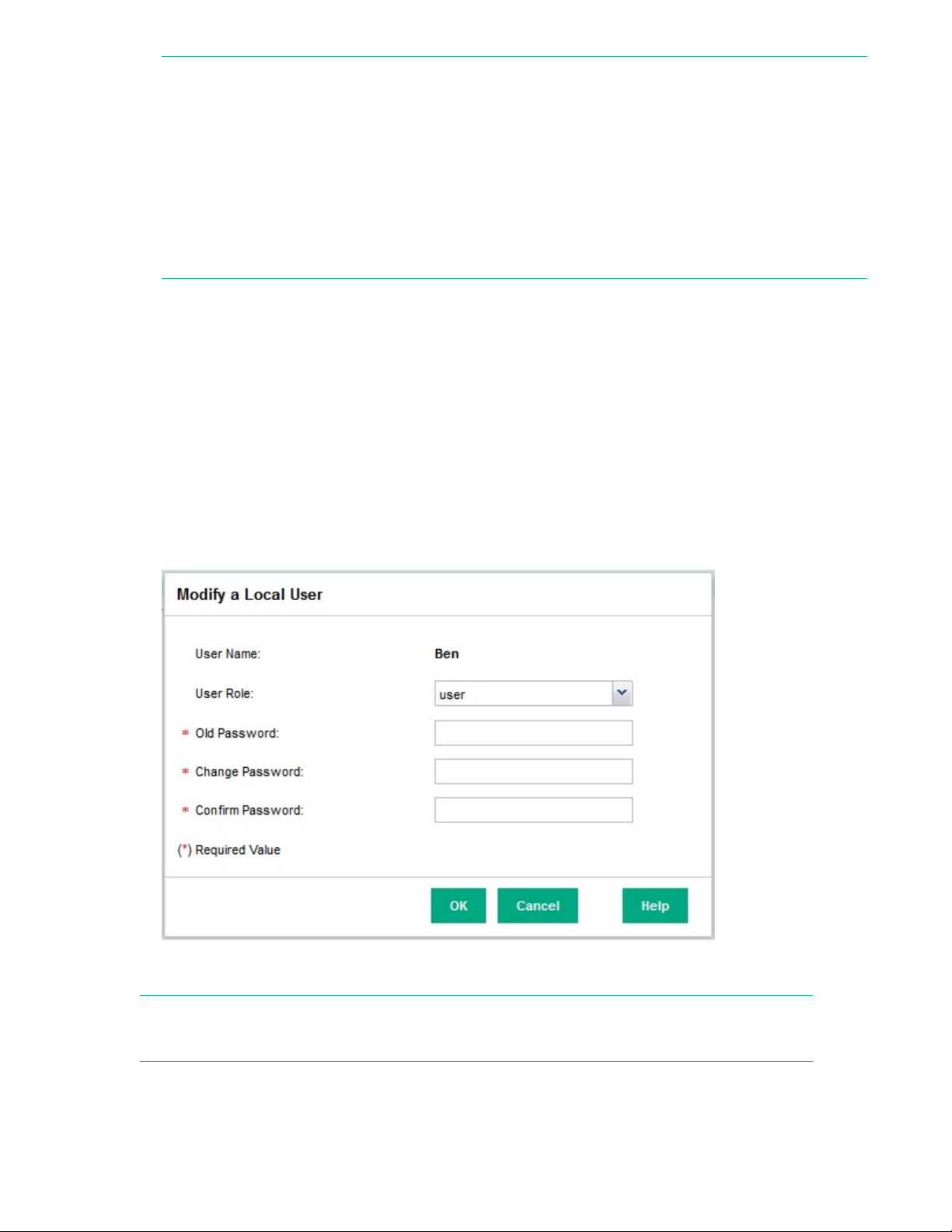
Procedure
1. Log on as an Administrator and select User Management from the Device Configuration menu.
2. Select the user whose password you wish to change and click Modify. For a local user, you can
modify the user role or the user password, or both.
3. Change the role of the user, if required. Enter and confirm the new password.
4. Click OK. At the confirmation of success page, click OK.
NOTE:
See the HPE StoreOnce System User Guide for more information about managing external users.
42 Changing passwords for local users
Page 43

Setting up StoreOnce email alerts
Email setup page
The Email Setup page displays the current configuration for sending out event notifications—which may
be Warnings, Alerts or Information—via email. The Email Setup page includes information needed to
route the email (SMTP server), as well as the association of event types with destination email addresses.
A single event can generate a notification to multiple email addresses. Also, different sets of events can
generate notifications to different email addresses.
Select Email from the Device Configuration menu item to display the current email setup.
Configuring email settings
Procedure
1. Click Configure.
2. Enter the required details and click OK.
Table 8: Email setup parameters
Name Description
Enable email
notification
SMTP Server The mail server used to send out the email.
Port number The SMTP port for the outgoing mail server.
Mail From The address from which the notification email originates.
Reply To An optional address if you want the recipient to reply to an email address
Testing email
Procedure
1. Click Test to open the Test Email dialog.
2. Enter the destination email address and a subject, then click OK.
Whether email notification is currently enabled or disabled. When email
notification is disabled, the association between events and destination
addresses remains valid, but the events do not produce email.
different from the address where the email originated.
3. An email message is sent only if email notification is enabled on the Email Setup page.
Email Events notification
Email events are listed under Events from the Email menu option in the Navigator.
Setting up StoreOnce email alerts 43
Page 44

The Events notified by email page lists the event types that may be notified by email and the addresses
to which the email notifications are sent. There are three types of events that generate email notifications,
listed under the Severity column once they have been setup in Manage Email Notifications. If the same
event generates email notifications to multiple addresses, a separate row is used to represent each
event/email-address pairing. The fields are:
Table 9: Events notified by email parameters
Name Description
Severity Severity of the event (INFO/WARN/ALERT).
Email Destination The email destination address.
Managing email notifications
Procedure
1. Click Manage Email Notifications to update the event/email-address association list.
2. On the Manage Email Notifications dialog, do one of the following:
44 Managing email notifications
Page 45

a. Choose an existing email address from the drop-down menu and rhwn click Select to display it in
the Update events for addresses field.
b. Enter a new address directly into the Update events for addresses field.
3. Select the event group(s) to be associated with the addresses (Alert, Warn, and/or Info), and click OK
to update the list. The updated list is displayed almost immediately in the Events Notified by Email
topic page.
Setting up StoreOnce email alerts 45
Page 46

Setting up SNMP (Simple Network Management Protocol)
Management Information Bases (MIBs)
Two MIBs are used to represent the information handled by the StoreOnce System and they are called
SEMI-MIB.mib and TRAP-DESTINATIONS-MIB.mib. These must be downloaded and registered with the
Network Management application on the host, so that information from the StoreOnce System can be
transmitted to and interpreted by the Network Management host, such as Insight Remote Support.
If this is the first StoreOnce System to be added to the network, you must download the MIBs,
Management Information Bases and register the MIBs with the Network Management application. You
can then use the StoreOnce CLI or StoreOnce GUI to set up the SNMP agent, for example with system
contact details, and to configure trap sinks and users.
When you connect subsequent StoreOnce Systems to the network, you only need to update the MIBs if
they are later models. For example, once you have downloaded the MIBs associated with StoreOnce
Systems, those MIBs are valid for all subsequent StoreOnce Systems and any earlier models that are
monitored by the Network Management application.
Setting up the Network Management application for use with the StoreOnce System
Procedure
1. To download the MIBs, go to the HPE Support website at http://www.hpe.com/support and search
for your StoreOnce System. Select the Software and driver downloads option and OS Independent
for the operating system. The MIBs are included under the MIB entry.
2. To set up the Network Management application for use with the StoreOnce System:
a. Register SEMI-MIB.mib and TRAP-DESTINATION-MIB within the base of MIBs supported by the
Network Management application.
b. Update the existing system type database with the new system type for the StoreOnce System,
based on the unique system object identifier.
c. Discover the StoreOnce System under the Network Management application.
For further information about setting up the Network Management application, refer to the MIB release
notes and to the documentation supplied with the Network Management application.
Configuring SNMP on the StoreOnce GUI
The default state at installation and after QR is off. SNMP may be enabled and configured from the
StoreOnce GUI or the StoreOnce CLI.
If you prefer to configure SNMP using StoreOnce CLI commands, refer to the StoreOnce CLI Reference
Guide.
46 Setting up SNMP (Simple Network Management Protocol)
Page 47
Procedure
1. In the Navigator select SNMP from Device Configuration.
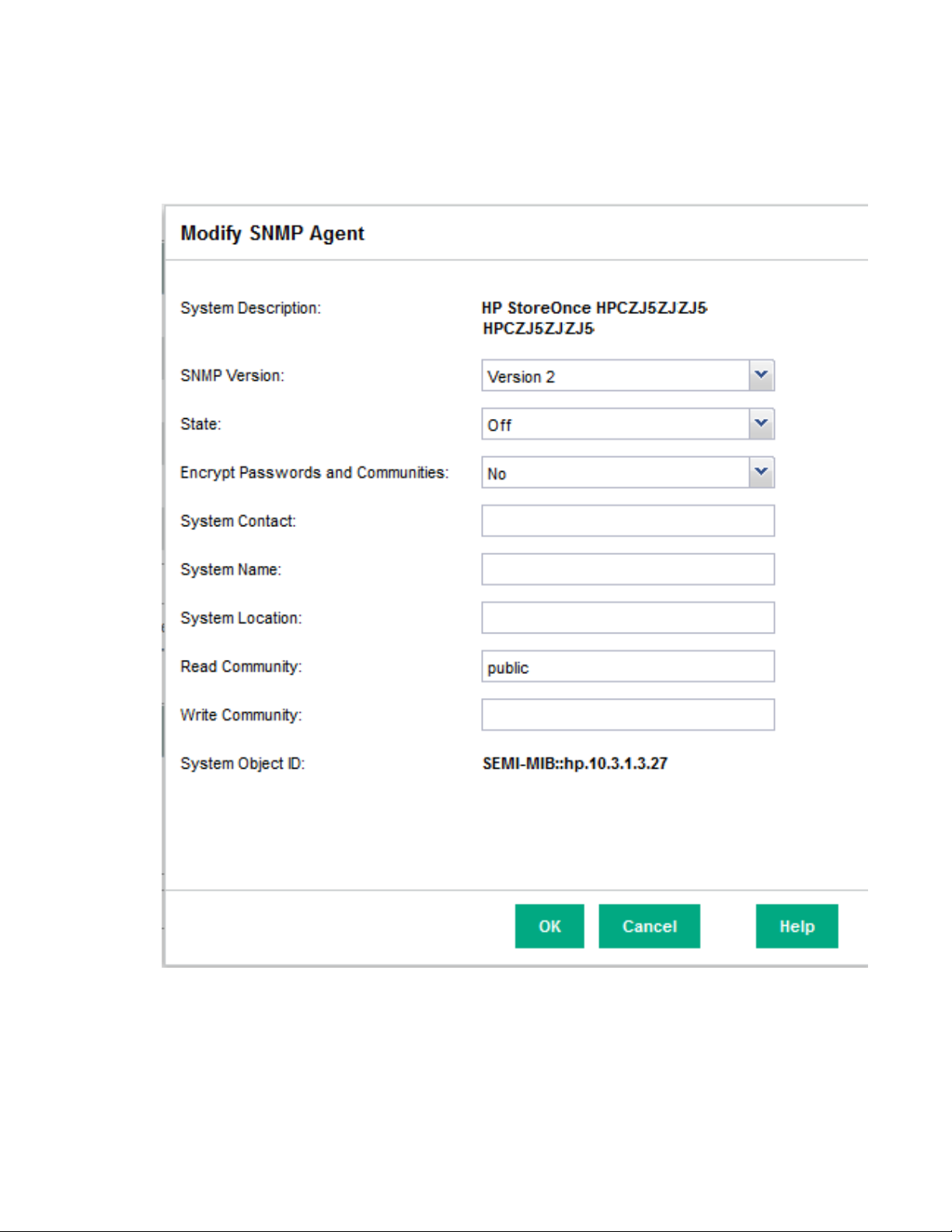
2. In the SNMP Agent Setup pane, click Modify.
3. In the Modify SNMP Agent window, change the State to On and modify other parameters, as
required.
4. Click OK.
5. Use the bottom half of the page to configure SNMP Trapsinks and SNMP Users. For more
information about the information shown on the SNMP Trapsinks and SNMP Users tabs, see the
Online Help or the user guide for your product.
Setting up SNMP (Simple Network Management Protocol) 47
Page 48

Table 10: SNMP Agent configuration parameters
Name Description
System description This is the description for the StoreOnce system configured for
the agent.
SNMP version This is the SNMP version of the agent (version 1, 2, or 3). The
default is 2.
State This shows the state of the agent (off, on).
Port This is the port location of the agent.
Encrypt Passwords and
Communities
System Contact This is the contact information for the system administrator,
System Location This is the physical location of the StoreOnce appliance. A
Read Community This defines the SNMP Read Community string. The default is
System Object ID The SNMP agent unique System Object ID. SNMP agents
Engine ID This optional device-specific parameter can be provided to an
This defines whether encryption for passwords and communities
is on or off.
which may be a name, email address, or phone number. A
maximum of 20 characters is allowed.
maximum of 20 characters is allowed.
public. If you want to restrict read access, enter a string of up to
20 characters. This string acts as a password for Read access
and must be manually configured in the management
application so that it can access events.
(running on a StoreOnce Device) supporting HPhttpManageable-MIB must provide a unique System Object ID.
This ID is used by network management entities to determine
the monitoring capabilities of a device.
SNMP version 3 trap listener device such as HP SIM (or any
third party tool) to listen to version 3 traps coming from the
device.
Allow non-V3 read requests This optional parameter can be provided during version 3
configuration. If the value is yes, versions 1 and 2 are supported
along with version 3. If the value is no, only version 3 is
supported. If this parameter is not configured, only version 3 will
be supported.
48 Setting up SNMP (Simple Network Management Protocol)
Page 49

Generating the SSL certificate
SSL certificates
The StoreOnce Management GUI is accessed via the HTTPS protocol which requires the exchange of an
SSL (Secure Sockets Layer) certificate to authenticate the connection between web browser and the
StoreOnce appliance. The StoreOnce appliance by default will return a generic SSL certificate which is
created when the system is manufactured. This generic certificate does not uniquely identify the
appliance, and therefore is not considered to be secure by the web browser.
The user has the option to change the SSL certificate to provide a better level of authentication. This
guide describes how to generate a self-signed certificate. If you wish to generate a certificate signing
request see the StoreOnce System User Guide.
Generating a self-signed certificate
Procedure
1. Select User Interface — SSL Certificate from the Navigator.
2. On the SSL Certificate page, click Modify.
3. Enter the requested information.
Field Description
Name Name of the system, in the form of either IP Address, or FQDN
State State the appliance is located in
City City the appliance is located in
Organization Organization of the certificate requestor
Organization unit Organization unit of the certificate requestor
Email address Email address of the certificate requestor
Country Country the appliance is located in
Number of days valid Maximum number of days the certificate will remain valid. Values are
0 to 36363
4. Click Generate. A message is displayed warning the user that the existing certificate will be
overwritten.
5. Click OK. A success message is displayed. The certificate is now stored locally on the system.
The new SSL certificate will not take effect until the StoreOnce appliance is rebooted.
Generating the SSL certificate 49
Page 50
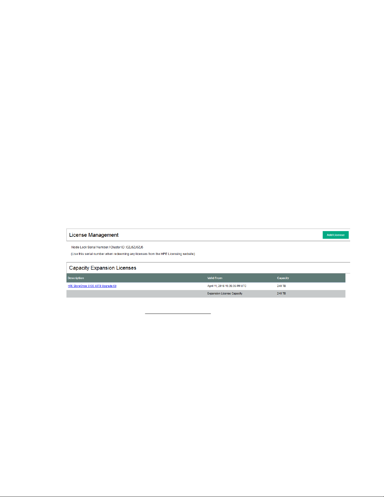
Expanding storage capacity, if supported
HPE StoreOnce 3500 Series
The HPE StoreOnce 3500 Series does not support the addition of storage expansion enclosures. It is
supplied with 12 disks installed. The StoreOnce 3540 model is supplied with twelve 4 TB disks installed;
the StoreOnce 3520 model is supplied with twelve 2 TB disks installed. The base configuration for both
models uses 50% of the available capacity (24 TB or 12 TB).
• If configured in the factory for the full capacity of 48 TB (3540 model) or 24 TB (3520 model), all
storage will already be licensed and is available for use without any further action.
• If not factory configured, the license entitlement will be delivered to the user via email. To complete
configuration of the storage, redeem the license and use the StoreOnce GUI to apply it. The expanded
storage is available for use; no further configuration is required.
Viewing license details
Procedure
1. Click Device Configuration in the Navigator pane. Select License Management.
2. Verify that there is a license for the Capacity Upgrade Kit.
3. If the license is missing, see StoreOnce full license on page 37 for information about applying
licenses.
Once the license is applied, the storage is available for use.
Viewing storage status
Procedure
1. Click Storage in the Navigator pane. Select the Storage Configuration tab.
An Information dialog box will appear that tells you to click Scan for Storage.
50 Expanding storage capacity, if supported
Page 51

2. Click OK.
3. Click Scan for Storage.
You will see a storage scan in progress message. The scan can take up to 5 minutes.
4. If storage has been pre-configured, the following prompt is displayed. Click OK.
5. The storage expansion configuration will be shown. See the online help for information about the fields
on this page.
Expanding storage capacity, if supported 51
Page 52

NOTE:
If the additional storage has not been pre-configured, there will be details in the Unconfigured
Storagesection. In the Capacity section there will be a value against the Unlicensed Capacitywith a
link to Apply License.
StoreOnce 5100 System and HPE StoreOnce 5500 System
There are two scenarios:
• Scenario 1: You have received the StoreOnce System from the factory pre-configured with additional
storage enclosures. This means that it is licensed and expanded ready for use. The label on the rear
of the Capacity Upgrade Kit identifies the server to which it belongs and the sequence in which it
should be installed.
• Scenario 2: You are adding one or more StoreOnce Capacity Upgrade Kits to an existing installation.
The storage will not be licensed or expanded.
IMPORTANT:
Storage expansion after installation with the HPE StoreOnce 5100 System and HPE StoreOnce
5500 System is beyond the scope of this guide. Please refer to the StoreOnce 5100 48 TB
Capacity Upgrade Kit Guide and the StoreOnce 5500 44 TB and 60 TB Capacity Upgrade
Guide supplied with the expansion enclosures for instructions.
52 StoreOnce 5100 System and HPE StoreOnce 5500 System
Page 53

Checking for the latest software
Checking the StoreOnce software version
It is good practice to verify that the system is running the latest software after installation.
Procedure
1. Click on StoreOnce in the Navigator and look at the Software Revision under System Information.
2. Check HPE Support to find out if a later software release is available at http://www.hpe.com/
support/softwaredepot.
3. Download the software release and follow the instructions in the accompanying Release Notes to
install the software.
Remote event reporting
It is a good idea to enable Remote Event Suppression mode when upgrading firmware and software.
When enabled, Remote Event Suppression flags all outbound event messages to let the HPE Support
team that the system is undergoing some form of maintenance, such as network reconfiguration, that
does not require a case to be raised with HPE Support. On the StoreOnce GUI select Events in the
Navigator and go to the Settings tab. Or use the StoreOnce CLI command system enable
remoteeventsuppression "reason", as described in the StoreOnce System CLI Reference
Guide.
Remote event suppression is automatically disabled after 24 hours or after a reboot. Or run system
disable remoteeventsuppression to re-enable normal event notification once you have finished
the software or firmware update.
More information
Configuring Remote Support on page 31
Viewing and upgrading firmware
When subsequently adding storage to a StoreOnce 5500 or 5100 System, or adding 10 GbE Network or
FC cards to a StoreOnce 5500, 5100 System or 3500 Series, it is also good practice to check for firmware
updates before installing the storage or Optional Hardware.
Procedure
1. Select Firmware from the Device Configuration menu item in the Navigator.
2. Click Scan to perform a check on the currently installed firmware versions for all components
associated to the selected node. This will populate the firmware tabs. This may take several minutes
to run.
NOTE:
The scan will fail if a firmware update is already in progress.
Checking for the latest software 53
Page 54

3. Look for components that have a Recommended Action of either Upgrade or Downgrade. After you
have run Scan or Scan All, components will automatically be selected for upgrade or downgrade.
NOTE:
When the firmware updates are initiated, the backup devices will be taken offline. Before performing
this step, check that there are no outstanding backup jobs pending.
• If there are only one or two, click in the appropriate check box to select them and click Update
Selected.
• If there are many, click Update All. This will attempt to update all components that are in the state
where there is an update recommended; it will not try to update components that do not need an
update.
4. The Status field will show which components are being updated and which updates have been
completed.
5. When all updates are completed, a reboot may be required.
NOTE:
In some cases, when the firmware update has completed, you will need to perform a cold boot. A popup message will appear on your GUI screen after updates are completed if a cold boot is required (a
cold reboot is a physical power cycle of the appliance while waiting for 60 seconds before powering
the appliance back up).
54 Checking for the latest software
Page 55

Complete network configuration
Initial StoreOnce network configuration
Assuming you have only configured LAN port 1 (eth0) at this point, you will have a network configuration
that contains a single Port Set on a 1 GbE network containing one Subnet. This is typically the network
connection for the StoreOnce Management Console. You can either edit the configuration or create a new
one to cater for the requirements of your networking environment.
For example:
• You may wish to use a bonded Port Set for the StoreOnce Management Console.
• HPE StoreOnce 3100 System: You may wish to configure the remaining 1 GbE ports for dedicated
backup and/or replication and StoreOnce Catalyst Copy.
• HPE StoreOnce 3500 Series, HPE StoreOnce 5100 System and HPE StoreOnce 5500 System: You
have the same 1 GbE configuration possibilities as the HPE StoreOnce 3100 System, but you may
also have 10 GbE Network cards installed.
• You may wish to configure VLAN subnets.
• You may wish to configure dual stack subnets (IPV4 with IPv6)
Make sure you understand your hardware and networking environment before creating the configuration.
More information
Optional PCIe cards on page 76
More about network configuration on page 79
Creating a StoreOnce custom network configuration overview
The following steps provide an overview of the process that is valid for both the StoreOnce GUI and
StoreOnce CLI..
Procedure
1. Create the configuration (or copy an existing one) and specify the DNS servers, as required.
2. Create the first Port Set and save the configuration. At this point you may decide to set up Subnets for
the Port Set, or to continue to set up all required Port Sets before defining Subnets for each Port Set.
3. Create the required Subnets for each Port Set and save the configuration.
4. Validate the configuration.
5. If validation fails, correct errors. If it passes, either activate immediately at the prompt. Or save the
configuration and activate subsequently from the Custom Network Configuration List.
Complete network configuration 55
Page 56

TIP:
If configuring multiple VLANs, or reconfiguring a complex network, it may take several minutes
for the configuration to activate. During this time the Current Configuration page will show the
previous configuration and will be updated once activation is complete for the new configuration.
The following examples illustrate how to use the StoreOnce GUI to create and activate a custom
network configuration. Users who are more accustomed to working with the StoreOnce CLI may prefer
to use the StoreOnce CLI command, net set wizard, as described in the StoreOnce CLI
Reference Guide.
Creating a new StoreOnce configuration and defining DNS servers
Procedure
1. On the Custom page, click on the New button.
2. Enter a Config Name. The name must be unique; spaces and special characters are not permitted but
underscore is allowed. The Config Description is optional. However, it is good practice to put the
configuration name into the description field because the description is copied to the current
configuration, when the configuration is activated.
3. Click on the Create button. At this point a new configuration will be opened for you to edit.
56 Creating a new StoreOnce configuration and defining DNS servers
Page 57

NOTE:
If there is an existing configuration that you wish to use as a template, select it from the Copy
Existing drop-down list.
4. As appropriate, select IPv4 or IPv6 for any DNS servers and enter the required addresses in the
appropriate format. Click Save.
Table 11: Network Configuration IP protocol and DNS fields
Field name Description
Name of the configuration This reflects the name of the configuration
selected in the list.
Protected This checkbox is always greyed out for the
Current and Factory Default configurations
because they cannot be edited. Custom
configurations can be edited and the checkbox is
active to indicate their protection status.
DNS server details:
These settings apply across all other settings.
Table Continued
Complete network configuration 57
Page 58
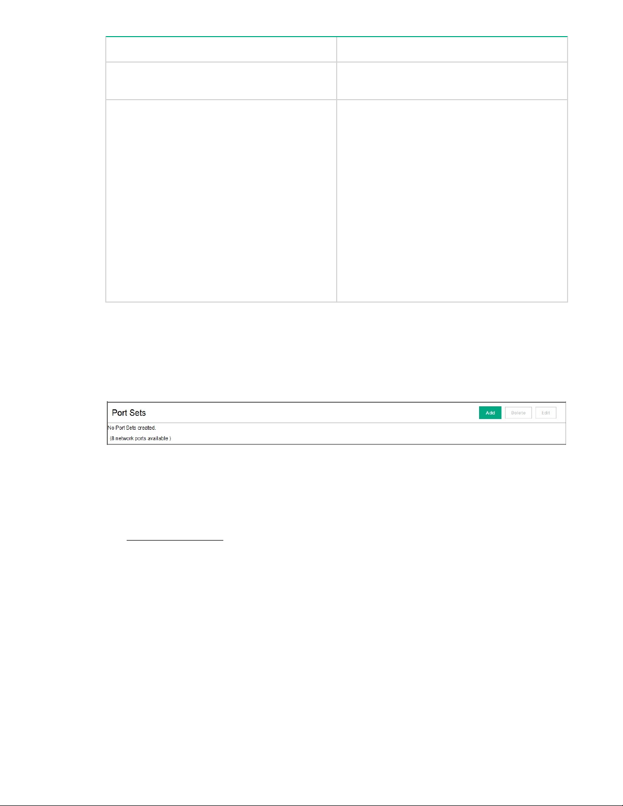
Field name Description
Protocol: IPv4 or IPv6 The radio button selected defines the Internet
DNS Address 1/2/3 Up to three IPv4 and/or IPv6 DNS addresses
Creating portsets
Protocol for the DNS servers.
may be defined. The format of the address
details is as appropriate for the protocol selected.
In order to use FQDNs “Fully Qualified Domain
Names” rather than an IP address to access the
StoreOnce System, the DNS server addresses
that you provide should be able to resolve
addresses for all configured subnets. If you are
using IPv4 and IPv6 addressing, then DNS
servers configured need to be able to resolve
both IPV4 and IPV6 FQDNs. Up to three DNS
servers (one primary, and two backup servers if
the primary is unavailable) may be configured for
the StoreOnce System, which have IPv4 and/or
IPv6 addresses.
Procedure
1. On the Port Set bar click Add to create the first Port Set.
2. Enter a name for the Port Set and select the ports to use. Available ports depend upon the model of
StoreOnce System and whether ports have already been assigned. Only those ports that are available
are active for selection; others are greyed out if they are already in use.
3. Some hardware products support optional PCI-E cards for 10 Gbit Ethernet. If your system has these
cards installed, they are included in the Ports section with the network type clearly indicated.
See Optional PCIe cards on page 76 for more information about optional hardware.
4. Click on the Show Port Picture link to display a picture of the rear of the model with ports labeled.
58 Creating portsets
Page 59

Table 12: Network Configuration Port Set fields
Field name Description
Port Set Name The name of the Port Set
Ports The ports that have been defined for use by the Port Set and their
speed.
All hardware products have four 1Gbit ports. 10Gbit ports may be
available for some hardware products. This depends upon whether the
model supports 10Gbit Ethernet and whether network cards have been
installed.
Bond mode Any bond mode that has been defined. Bond modes are only
appropriate if there is more than one port in the Port Set.
VLAN Tagging Enable This defines whether the Port Set is VLAN enabled or not.
Frame size This defines the amount of data contained in an Ethernet frame, the
default is 1500 bytes. Larger size frames, often referred to as "Jumbo"
frames, can improve performance of the Port Set. Use this field to
increase or decrease the value, which must be an integer between
1280 and 9000.
IMPORTANT:
Other devices on the network (clients and switches) must also be
configured to enable Jumbo frames for transfer of frames larger
than 1500 bytes to be possible and to avoid packets fragmenting
or dropping.
If multiple ports are selected, the Bond Mode selection will be active.
5. If required, check the VLAN Tagging Enable box and click OK.
Complete network configuration 59
Page 60

NOTE:
VLAN tagging is not supported with Bonding Mode 6.
6. At this point you may choose to define the Subnets for the Port Set or to create additional Port Sets by
clicking on Add in the Port set section. For the purposes of this example, we shall continue to Subnet
configuration.
TIP:
It is good practice to Save the network configuration at regular intervals.
Creating subnets
Procedure
1. Select the Port Set and click Add in the Subnet section.
Table 13: Network Configuration New Subnet fields
Name Description
Name The name of the Subnet
Protocol Select IPv4 or IPv6.
60 Creating subnets
Table Continued
Page 61

Name Description
IP address The IP address for the subnet, in the appropriate format for
the protocol selected.
Default Subnet When checked, this box indicates that this is the Subnet that
contains the default gateway. A default subnet should be
provided for both IPv4 and IPv6 networks.
Network Mask (IPv4 only) The network mask
Prefix (IPv6 only) The network prefix in CIDR format
Domain Name The domain name
VLAN tag The VLAN tag ID (2 to 4096)
2. Provide the Subnet details, and then click OK.
• For IPv4 Subnets, select the IPv4 button and provide the relevant details.
• For IPv6 Subnets, select the IPv6 button and provide the relevant details.
DHCP Subnets may support both IPv4 and IPv6 protocols.
3. Repeat until all the Subnets for the selected Port Set have been defined.
Each physical Port Set may be configured with one Subnet that uses the IPv4 protocol and one
Subnet that uses the IPv6 protocol.
If the Port Set is VLAN enabled, it is possible to add a total of 128 IPv4 and 128 IPv6 VLAN Subnets.
These total values apply across the whole network configuration, not per Port Set.
If DHCP is used, one IPv4 and one IPv6 subnet will be consumed.
4. Click Save to save all configuration details.
Validating and activating the StoreOnce configuration
Procedure
1. Click Validate to validate the network configuration. If there are any errors, the error message will
guide you to the parts of the configuration that need correcting. Make the necessary changes, save
them and click Validate again.
2. If validation is successful, you have two choices. The StoreOnce System Management GUI will prompt
you to activate the new configuration immediately. Or you can save it and activate it separately from
the Network Configuration — Custom page.
NOTE:
It is not possible to activate a new configuration if storage addition is in progress.
Validating and activating the StoreOnce configuration 61
Page 62
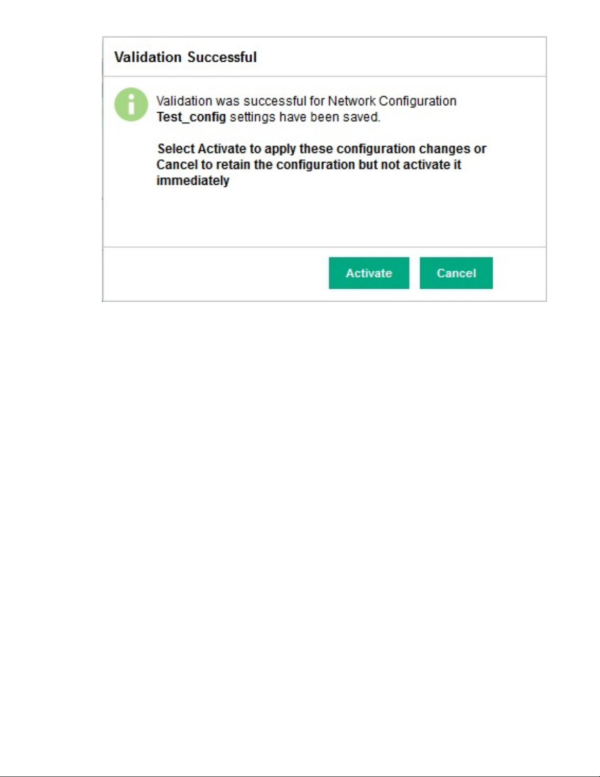
62 Complete network configuration
Page 63

Additional configuration tasks
Post StoreOnce configuration
Once you have completed configuration tasks for the StoreOnce System, be sure to save the
configuration and run a system confidence check.
Depending upon your backup environment. it may also be necessary to configure the media servers that
are backing up to the StoreOnce System.
Saving the StoreOnce configuration and keystore
Contents of the StoreOnce configuration file
It is strongly recommended to save the configuration whenever you make changes to it.
The configuration consists of two parts:
1. A set of instructions in the form of a text file, devconfig<timestamp>.txt, for the user to manually
restore some of the network and device management configuration settings that cannot be
automatically restored.
2. A zip file, devconfig<timestamp>.zip, containing StoreOnce device configuration settings that
automatically restore configuration settings that have been created for StoreOnce VTL, NAS, Catalyst,
Replication and housekeeping functions.
IMPORTANT:
If settings in the text file need to be restored, the manual restore should always be carried out
before the automatic restore. See the StoreOnce System User Guide for more information about
saving and restoring configurations.
Saving the StoreOnce configuration
Procedure
1. Open the puTTy (or other ssh) application and login to the StoreOnce CLI as an Admin user. Save
the configuration using the StoreOnce CLI command:
config save devices
2. Using sftp protocol and an application, such as filezilla, copy the following files from /config
to your local machine.
• devconfig_<cluster ID and serial number><date and time>.zip
• devconfig_<cluster ID and serial number><date and time>.txt
The StoreOnce encryption keystore
If you have installed the Security license and are applying encryption to devices on the StoreOnce
System, encryption keys are created and are written to a keystore which may be managed locally on the
StoreOnce System or externally using a Key Manager utility. The keystore should be backed up regularly
Additional configuration tasks 63
Page 64

and saved securely offsite in case the original keystore is corrupted. It is important to keep only the latest
version of the keystore.
The StoreOnce CLI command config save keystore that backs up the key store, also encrypts it,
ensuring that it can only be decrypted by the StoreOnce System, should you need to restore it.
NOTE:
Data at rest and Data in flight encryption are the security features that can be applied using the Security
license (which must be purchased and applied in the normal way).
Running a StoreOnce system confidence check
It is good practice to use the StoreOnce CLI command, system confidencechecker at the end of
installation to run a self-test report on the StoreOnce System. For the products described in this guide,
this will report on any problems with the File System and external network connections. Refer to the
StoreOnce System CLI Reference Guide for more information about using this command.
Example
system confidencechecker runtest all
Confidence checks running. Checks will take maximum of 60 seconds. Please wait...
###############################################################################
# #
# CONFIDENCE REPORT #
# #
###############################################################################
Report Date: Wed Nov 18 11:55:40 UTC 2017
Product ID: HPE StoreOnce 3540 System
Cluster S/N: XXXXXNNNNNNXX
Version: 3.16.0-16xx.x
Test Type: all
### FILE SYSTEM REPORT ########################################################
File System Check:
[RESULT]
PASSED
### INTERNAL NETWORK REPORT ###################################################
Internal Network Check is supported only on HP StoreOnce multinode products.
### EXTERNAL NETWORK REPORT ###################################################
External Network Check:
[RESULT]
PASSED
### SAS CONFIGURATION REPORT ##################################################
Sas Configuration Check is supported only on HP StoreOnce multinode, 5500 and 4900 backup products.
### NOTE ######################################################################
For any warning or error messages in this report, please consult the troubleshooting
section in the customer user guide and follow the steps to perform corrective action.
64 Running a StoreOnce system confidence check
Page 65

### END #######################################################################
Command Successful
Defining a new remote host to receive StoreOnce audit log events
With StoreOnce software version 3.15.0 and later, it is possible to define a remote host to receive
StoreOnce audit log events. This is done using StoreOnce CLI logs commands. It may also be
necessary to configure the remote host to receive the log events offload.
Procedure
1. Log in to the StoreOnce CLI as an Admin user.
2. Run the following StoreOnce CLI command to add each remote host, who may be on an IPv4 or an
IPv6 network:
logs add recipient <ip> <protocol> [port]
3. Upon successful completion of the command, confirmation that the host has been added to the list of
remote syslog recipients will be displayed. For example:
# logs add recipient 192.192.1.1 UDP
# logs add recipient 192.192.10.1 tcp 5500
4. Many log programs will not require additional configuration on the target system to receive the log
offload. However, if you are using the standard syslog linux deamon (rsyslog) to receive the
logs, ,add the following to the /etc/rsyslog.conf file.
$MaxMessageSize 100k
# provides UDP syslog reception
$ModLoad imudp
$UDPServerRun 514
# provides TCP syslog reception
$ModLoad imtcp
$InputTCPServerRun 514
More information
There are three StoreOnce CLI logs commands to add, delete and view log recipients. Refer to the
StoreOnce System CLI Reference Guide for more information about using them.
For log programs, other than rsyslog, refer to the software vendor for other applications for any
configuration details.
Aggregating login event notifications
The event logging component generates one event for each Login and each Logout, and two events for
each failed Login attempt. With StoreOnce software version 3.15.0 and later, there is a StoreOnce CLI
command that allows the Admin user to set a time period during which login, logout and failed login
events from a user will be aggregated. Only the first occurrence within the defined period will be logged.
Defining a new remote host to receive StoreOnce audit log events 65
Page 66

Procedure
1. Log in to the StoreOnce CLI as an Admin user.
2. Decide on the event aggregation period which may be between 0 and 30 minutes.
3. Run the StoreOnce CLI command, system set eventaggregation period <X>.:
For example:
# system set eventaggregation period 5
event aggregation period set to : 5 minute(s).
This will take effect from the next aggregation window.
Command Successful.
#
Configuring media servers to use StoreOnce Catalyst
With HPE Data Protector the StoreOnce deduplication engine is embedded in the HPE Data Protector
Media Agent. No additional plug-ins are required. For other backup environments HPE has developed
OpenStorage (OST) Plug-ins that create the interface between the backup application and the StoreOnce
Catalyst store.
1. To find out what Plug-Ins are available and required go to
StoreOnce Catalyst license is required to use the Plug-ins.
2. To download the free software go to http://www.hpe.com/support/softwaredepot.
3. Search for StoreOnce in the Search Software Depot search box.
4. The search result includes the StoreOnce System Software for all products, VSA evaluation files, and
QR images for all hardware platforms, plus a link to StoreOnce Free Software. Click on StoreOnce
Free Software to access the Plug-ins.
5. Follow the instructions included in the download to install the plug-ins. The download includes release
notes and documentation.
http://www.hpe.com/info/ebs. A
Drivers for StoreOnce VTL devices on client servers
To create Virtual Tape Devices on the StoreOnce System, two drivers are required on the client server:
• HP LTO Tape driver: allows your system to recognize the Ultrium tape devices created by the
StoreOnce System.
Tape drivers can be installed from the HPE website for driver updates at http://www.hpe.com/
support/hpesc. Search on the Product name and select Download Drivers and Software.
• Medium changer driver: No additional medium changer driver is required because Microsoft Windows
provides a suitable generic driver and all backup applications provide their own changer drivers.
66 Configuring media servers to use StoreOnce Catalyst
Page 67

NOTE:
Certain backup applications require their own drivers for both the tape device and medium changer. For
many applications these are installed automatically during the software installation process. If the backup
software is already installed, you may need to update manually the drivers after installing the StoreOnce
System.
After installation, the StoreOnce System does not appear as a device under My Computer and it is not
mapped to a drive letter. The host machine requires a backup application to back up and restore data.
However, if drivers are installed, the backup system can be viewed as a tape drive and medium changer
from the Device Manager.
NOTE:
For a Fibre Channel StoreOnce system, a new “unknown” device will be discovered in Device Manager.
This device is required only to ensure that a Fibre Channel target exists as LUN 0 in the SAN. No
functionality is provided by this device and no driver is required. Note that this device will be replaced by
the Catalyst Over Fibre Channel initiator device if CoFC is configured.
iSCSI Initiator (StoreOnce VTL)
iSCSI is a protocol for sending SCSI commands via Ethernet. It defines how SCSI packets are translated
to Ethernet packets and connects to the required devices. An iSCSI initiator may be hardware or software
and should be running on each host. If the host does not have an iSCSI initiator, it will not be able to
connect to the library configured on the StoreOnce System and will not be able to perform backups.
For Linux and UNIX operating systems an iSCSI initiator is embedded in the operating system. Please
refer to the StoreOnce System Linux and UNIX Configuration Guide for further information. Make sure
that you have downloaded the latest operating system patches before you configure your system.
For Windows systems the Microsoft iSCSI initiator is required to connect to any Virtual Tape Libraries
created on the StoreOnce System. The iSCSI initiator ships with later versions of Microsoft Windows, but
not with Windows 2003 or earlier. So, if required, it must be retrieved from the Microsoft website.
NOTE:
With some versions of Windows the iSCSI initiator service is not started by default. This component must
be configured manually by the user to run on startup. Refer to Windows documentation for more details.
iSCSI Initiator (StoreOnce VTL) 67
Page 68
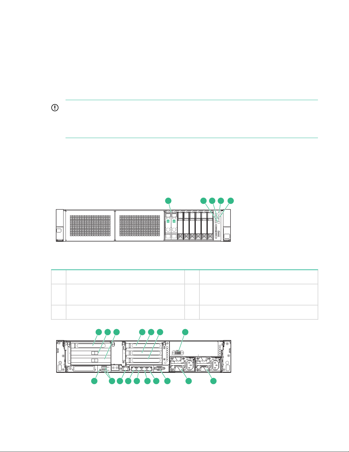
Hardware overview reference section
SID
1 2 3 4 5 6 7 8
1 2
4 5321
1
2
3
4
1
5
6
4
4
1
iLO
PS2
PS1
111213151617 14 9 810
71 2 3 4 5 6
Optional hardware
All models, apart from the HPE StoreOnce 3100 System provide four PCIe slots for the addition of
StoreOnce 10 GbE Network Cards or StoreOnce Fibre Channel cards. These additional PCIe cards may
be pre-installed or supplied in separate boxes. Some cards also require SFP+ transceivers, which will be
supplied with the kit.
IMPORTANT:
Refer to the StoreOnce Optional Hardware Installation and Configuration Guide for detailed
instructions about installing and cabling optional PCIe cards and make sure the correct SFP+
transceivers are fitted, if required.
HPE StoreOnce 5500 System
HPE StoreOnce 5500 System front and rear views, server
For more information about LEDs see the HPE StoreOnce 5500 System Maintenance and Service Guide.
Figure 8: HPE StoreOnce 5500 System server front view
1 OS disks 2 UID button LED
3 NIC status LED 4 Power on/standby button and system power
5 Health LED
Figure 9: HPE StoreOnce 5500 System server rear view
68 Hardware overview reference section
LED
Page 69
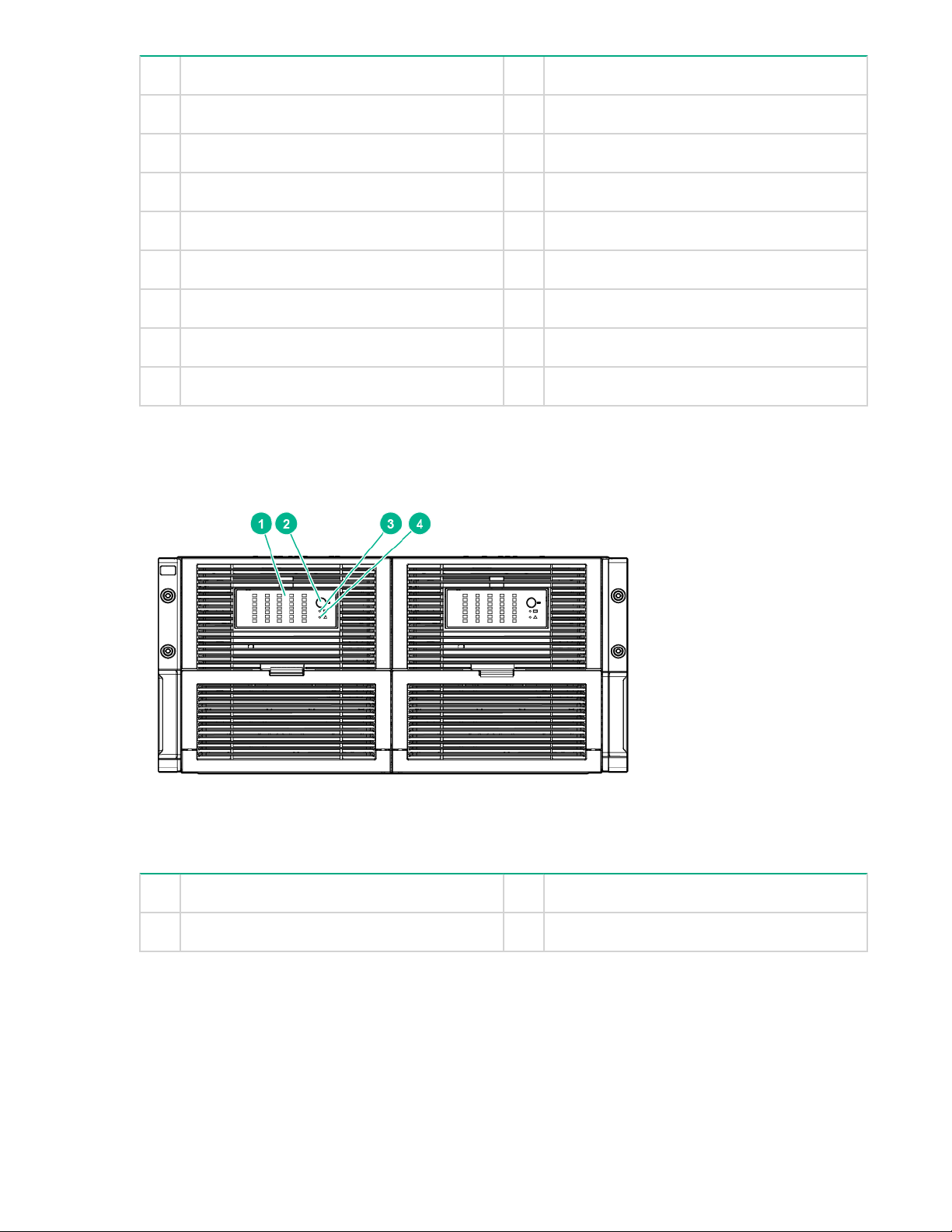
1 Slot 1, available for Optional Hardware 2 Slot 2, first RAID controller card
3 Slot 3, second RAID controller card 4 Slot 4, available for Optional Hardware
5 Slot 5, available for Optional Hardware 6 Slot 6, available for Optional Hardware
7 Optional serial port 8 Power supply 1 (PS1)
9 Power supply 2 (PS2) 10 Video connector
11 1Gb RJ45 Port 4 12 1Gb RJ45 Port 3
13 1Gb RJ45 Port 2 14 1Gb RJ45 Port 1 (eth0)
15 iLO4 connector 16 USB connectors
17 Rear UID LED
Front and rear views of the disk enclosure
For more information about LEDs see the HPE StoreOnce 5500 System Maintenance and Service Guide.
Figure 10: Front view of HPE StoreOnce 5500 System disk enclosure
1 Hard drive LEDs 2 UID button/LED
3 Internal health LED 4 GSI LED
Front and rear views of the disk enclosure 69
Page 70
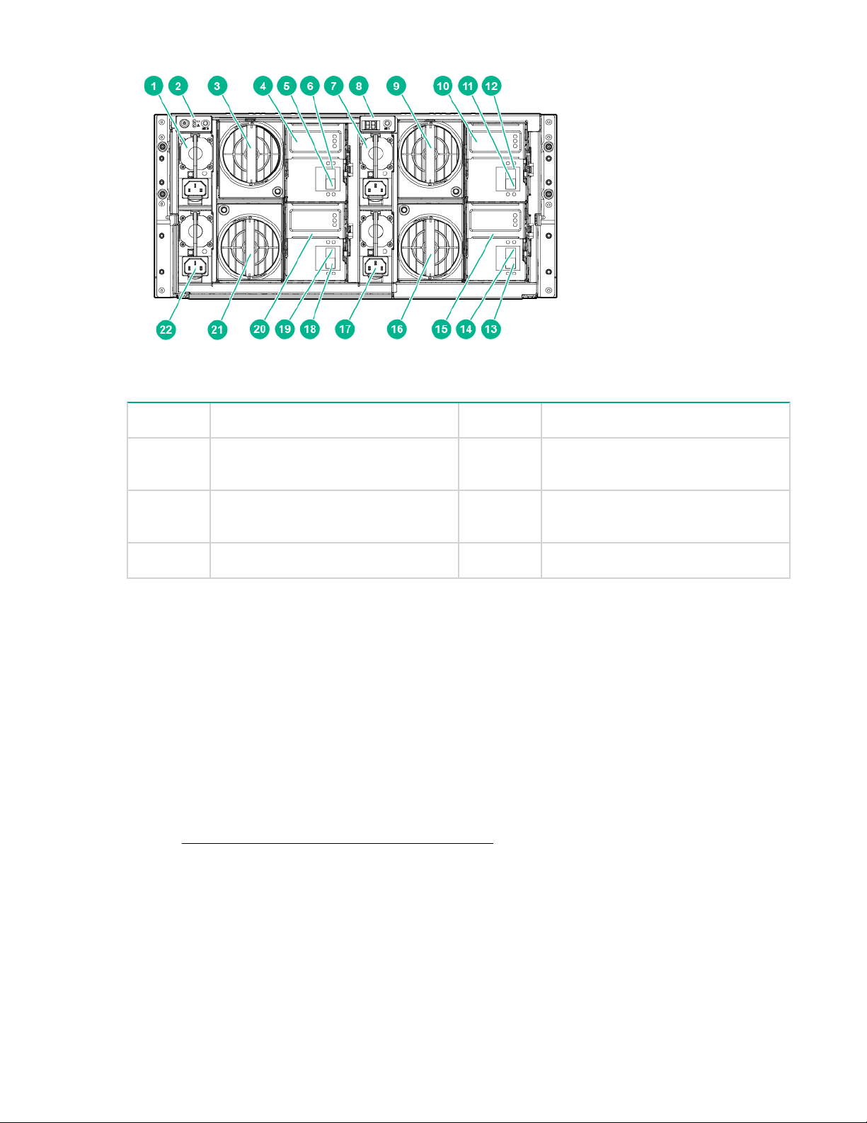
Figure 11: Rear view of HPE StoreOnce 5500 System disk enclosure
1, 7, 17, 22 Power supplies 2 Power On/Standby button and LEDs
3, 9, 16, 21 Fans 4, 10, 15,20I/O module LEDs
5, 11, 13,18I/O module SAS port 1 6, 12, 14,19I/O module SAS port 2
8 Display
Storage expansion
The HPE StoreOnce 5500 System supports capacity expansion. The server element is used for OS disks
only; base storage in the disk enclosure consists of 11 x 4 TB disks plus four hot plug disks. The HPE
StoreOnce 5500 System supports two models of capacity expansion.
• 44 TB Capacity Upgrade Kit: this is a pack of 11 x 4 TB disks which are added to an enclosure. Up to
five packs may be added to the base storage in a disk enclosure.
• 60 TB Capacity Upgrade Kit: this is an additional enclosure with base storage of 11 x 4 TB disks plus
four hot plug disks. Up to three further 60 TB Capacity Upgrades may be connected, and these may
also be expanded using the 44 TB Capacity Upgrade kits. It is not necessary to fill an enclosure before
adding the next.
Refer to SAS cabling for HPE StoreOnce 5500 Systems on page 12 for cabling examples,
HPE StoreOnce 3100 System
The HPE StoreOnce 3100 System comprises a 1U 4–disk server, that provides four 1 GbE ports for
connecting to an Ethernet network. It does not support 10 GbE Network or Fibre Channel connection.
The base configuration has a single power supply.
70 Storage expansion
Page 71

1
6
3
5
4
2
Figure 12: HPE StoreOnce 3100 System front view
1 2 3
4 5
6
7
8
91011
12
13
1 Pull out label with serial number 2 USB 3.0 port
3 UID LED 4 NIC status LED
5 Health LED 6 Power on/standby button and system power
LED
Figure 13: HPE StoreOnce 3100 System rear view
1 Slot 1, RAID controller 2 Slot 2 (not used)
3 Slot 3 (not used) 4 Power supply 2 (optional, must be
5 Power supply 1 6 Video connector
7 1Gb RJ45 Port 4 8 1Gb RJ45 Port 3
9 1Gb RJ45 Port 2 10 1Gb RJ45 Port 1 (eth0)
11 iLO4 connector 12 Serial connector
13 USB connectors
HPE StoreOnce 3500 Series
purchased)
HPE StoreOnce 3500 Series 71
Page 72
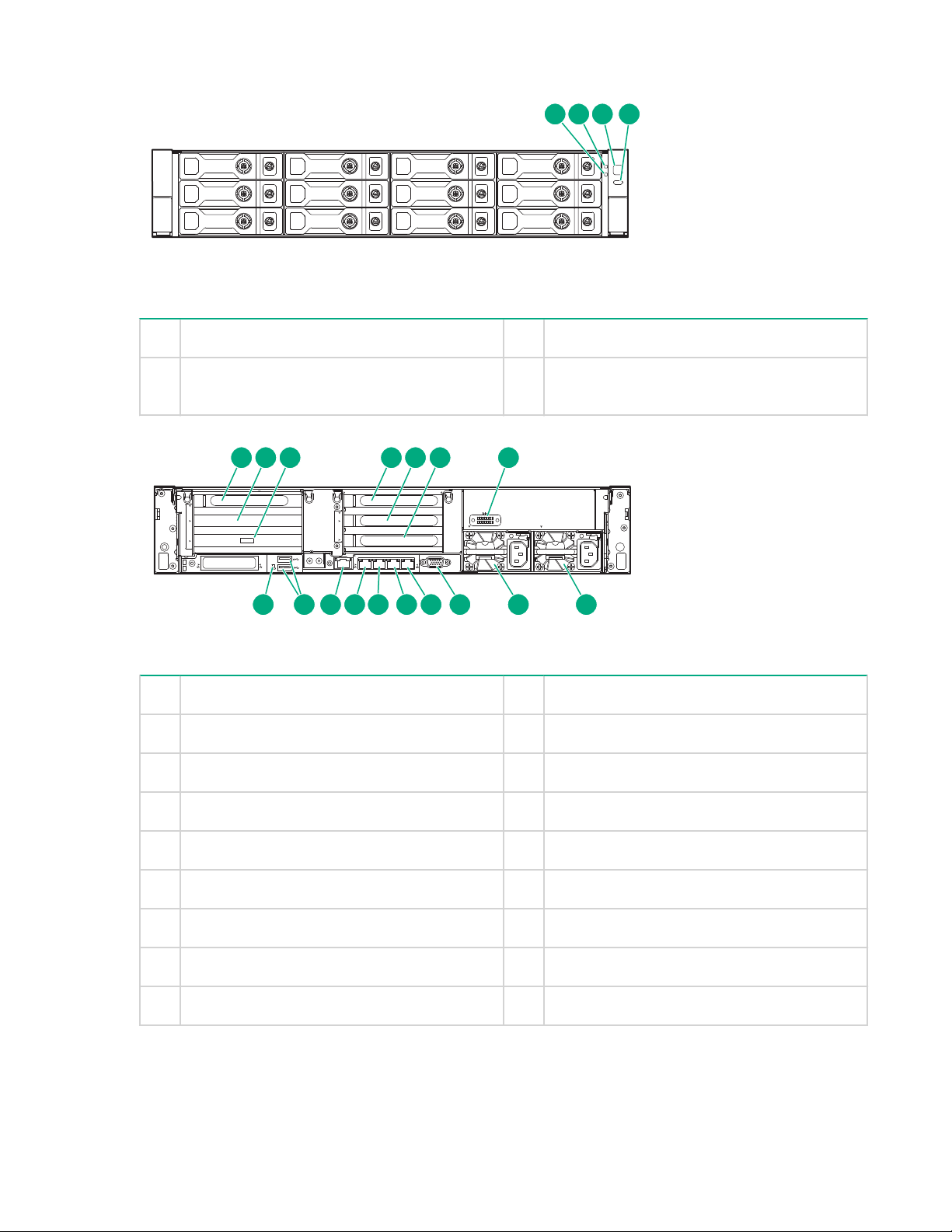
Front and rear views
3 421
1
2
3
4
1
5
6
4
4
1
iLO
PS2
PS1
1 2 3 4 5 6 7
891011121314151617
Figure 14: HPE StoreOnce 3500 Series front view
1 NIC status LED 2 Health LED
3 Power on/standby button and system power
4 UID button LED
LED
Figure 15: HPE StoreOnce 3500 Series rear view
1 Slot 1, available for Optional Hardware 2 Slot 2, SAS expander card
3 Slot 3, RAID controller card 4 Slot 4, available for Optional Hardware
5 Slot 5, available for Optional Hardware 6 Slot 6, available for Optional Hardware
7 Optional serial port 8 Power supply 1 (PS1)
9 Power supply 2 (PS2) 10 Video connector
11 1Gb RJ45 Port 4 12 1Gb RJ45 Port 3
13 1Gb RJ45 Port 2 14 1Gb RJ45 Port 1 (eth0)
15 iLO4 connector 16 USB connectors
17 Rear UID LED
Storage expansion
The HPE StoreOnce 3500 Series does not support the addition of storage expansion enclosures. It is
72 Front and rear views
supplied with 12 disks installed.
Page 73

• The StoreOnce 3540 model is supplied with twelve 4 TB disks installed.
3 421
1
2
3
4
1
5
6
4
4
1
iLO
PS2
PS1
1 2 3 4 5 6 7 8 9
10111213141516171819
• The StoreOnce 3520 model is supplied with twelve 2 TB disks installed.
The base configuration for both models uses 50% of the available capacity (24 TB or 12 TB). If configured
in the factory for the full capacity of 48 TB (3540 model) or 24 TB (3520 model), all storage will already be
licensed. If not factory configured, the license entitlement will be delivered to the user via email.
IMPORTANT:
When increasing storage capacity from 50% to 100%, the only installation and configuration task is
to apply the license for the additional capacity.
HPE StoreOnce 5100 System
Front and rear views
Figure 16: HPE StoreOnce 5100 System front view
1 NIC status LED 2 Health LED
3 Power on/standby button and system power
4 UID button LED
LED
Figure 17: HPE StoreOnce 5100 System rear view
1 Slot 1, available for Optional Hardware 2 Slot 2, SAS expander card
3 Slot 3, RAID controller card 4 Slot 4, available for Optional Hardware
Table Continued
HPE StoreOnce 5100 System 73
Page 74
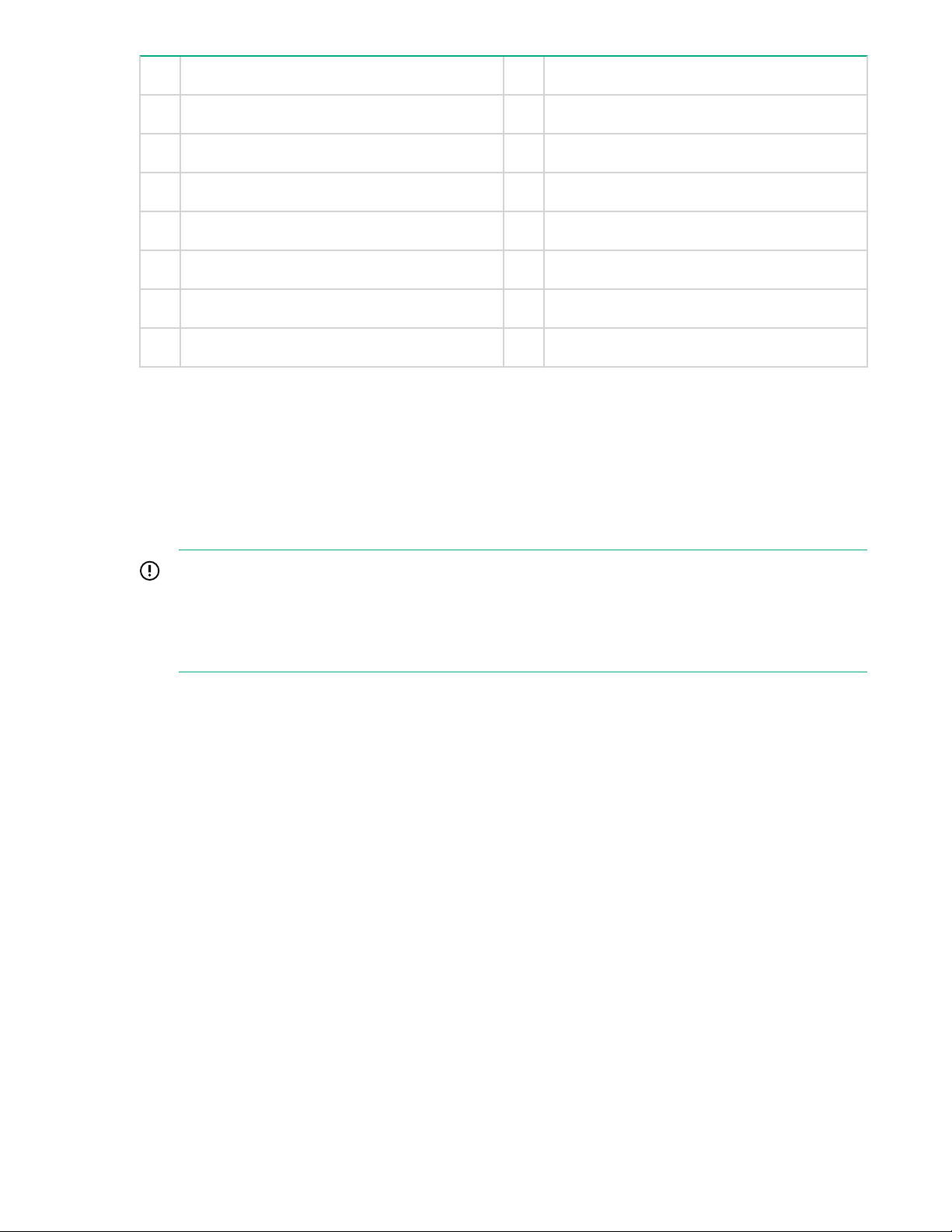
5 Slot 5, available for Optional Hardware 6 Slot 6, available for Optional Hardware
7 Optional serial port 8 OS drive 1
9 OS drive 2 10 Power supply 1 (PS1)
11 Power supply 2 (PS2) 12 Video connector
13 1Gb RJ45 Port 4 14 1Gb RJ45 Port 3
15 1Gb RJ45 Port 2 16 1Gb RJ45 Port 1 (eth0)
17 iLO4 connector 18 USB connectors
19 Rear UID LED
Storage expansion
The StoreOnce 5100 System supports capacity expansion. The base configuration consists of 12 x 4 TB
disks. Up to five 48 TB Capacity Upgrade Kits may be added to the base configuration. These are factory
configured and will have a label in the format: JBOD # for <server_warranty_number>. The Capacity
Upgrade Kits must be connected to the correct HPE StoreOnce 5100 System in the recommended
sequence. If they are not, the StoreOnce 5100 System will not be able to discover the storage and make
it available for use.
IMPORTANT:
For ease of installation HPE recommends daisy chaining Capacity Upgrade Kits so that all
enclosures are either above or below the server. The supplied SAS cable supports this
configuration. Different length SAS cables (up to a maximum of 2 m) are available, but these must
be ordered separately.
The following drawing illustrates a fully expanded StoreOnce 5100 System. Refer to the HPE StoreOnce
5100 48TB Capacity Upgrade Kit Guide for detailed instructions about installing and configuring
Capacity Upgrade Kits both at initial installation and at a later date.
74 Storage expansion
Page 75
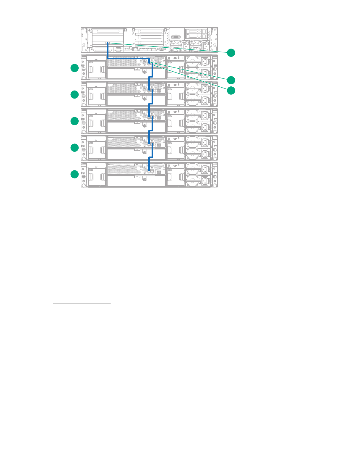
1
2
3
4 1
5
6
4
4
1
iLO
PS2
6
7
8
1
2
3
4
5
Figure 18: Cabling showing five Capacity Upgrade Kits below the server
1 JBOD1 2 JBOD2
3 JBOD3 4 JBOD4
5 JBOD5 6 SAS connector on RAID controller on
head unit
More information
7 P1 connector on I/O module (SAS IN from
head unit or previous expansion shelf)
StoreOnce full license on page 37
8 P2 connector on I/O module (SAS OUT to
next expansion shelf)
Hardware overview reference section 75
Page 76

Optional PCIe cards
StoreOnce Optional Hardware with StoreOnce 35xx and 5xxx models
StoreOnce software supports the addition of 10 GbE Network and/or Fibre Channel PCIe cards for the
StoreOnce models listed in the table below.
Table 14: PCIe slot configuration options for StoreOnce Systems
Product Name PCIe slots available for
additional cards
HPE StoreOnce 3100 System None The addition of 10 GbE and/or
HPE StoreOnce 3500 Series Four: slots 1, 4, 5 and 6 10 GbE SFP or 10 GbE-T
HPE StoreOnce 5100 System Four: slots 1, 4, 5 and 6 10 GbE SFP or 10 GbE-T
HPE StoreOnce 5500 System Four: slots 1, 4, 5 and 6 10 GbE SFP or 10 GbE-T
PCIe slot allocation at delivery
Card choices
FC cards is not supported
Network card
8 Gb or 16 Gb Fibre Channel
card
Network card
8 Gb or 16 Gb Fibre Channel
card
Network card
8 Gb or 16 Gb Fibre Channel
card
If you have ordered additional PCIe cards with the base product, the StoreOnce System will have the
correct cards installed in the correct PCIe slots, and they will be configured and licensed when the
product is supplied. You must insert the SFP transceivers, if required, attach the appropriate cables and
connect to the network or FC SAN.
IMPORTANT:
For detailed information about installing additional PCIe cards after initial delivery, see the
StoreOnce Optional Hardware Installation and Configuration Guide.
The following drawing illustrates the rear view of a StoreOnce 5100 System. Remember that:
• The cards installed in each slot are determined by your purchase order, so any illustrations are
examples only.
• The PCIe cards must be installed in the correct slot sequence.
76 Optional PCIe cards
Page 77

◦ For connection to Ethernet, the 10 GbE network cards must be installed, starting with slot 1, in the
1
2
3
4
1
5
6
4
4
1
iLO
PS2
PS1
1 2 3 4
1
2
3
4
1
5
6
4
4
1
iLO
PS2
PS1
21 21
slot sequence 1, 4, 5, 6.
◦ For connection to SAN, the FC cards must be installed, starting with slot 6, in the slot sequence 6,
5, 4, 1.
• SFP+ transceivers are required with the FC cards and the 10 GbE SFP cards. No additional hardware
is required for the 10 GbE Base-T cards.
NOTE:
The HPE StoreOnce 3100 System does not support the addition of PCIe cards.
Figure 19: Rear view of HPE StoreOnce 5100 System, highlighting additional PCIe slots
1 Slot 1, populated with 10 GbE card
2 Slot 4, populated with 10 GbE card
3 Slot 5, populated with FC card
4 Slot 6, populated with FC card
Port numbering on PCI cards
Figure 20: 10 GbE cards
1 Port 2 on 10 GbE cards
2 Port 1 on 10 GbE cards
Port numbering on PCI cards 77
Page 78
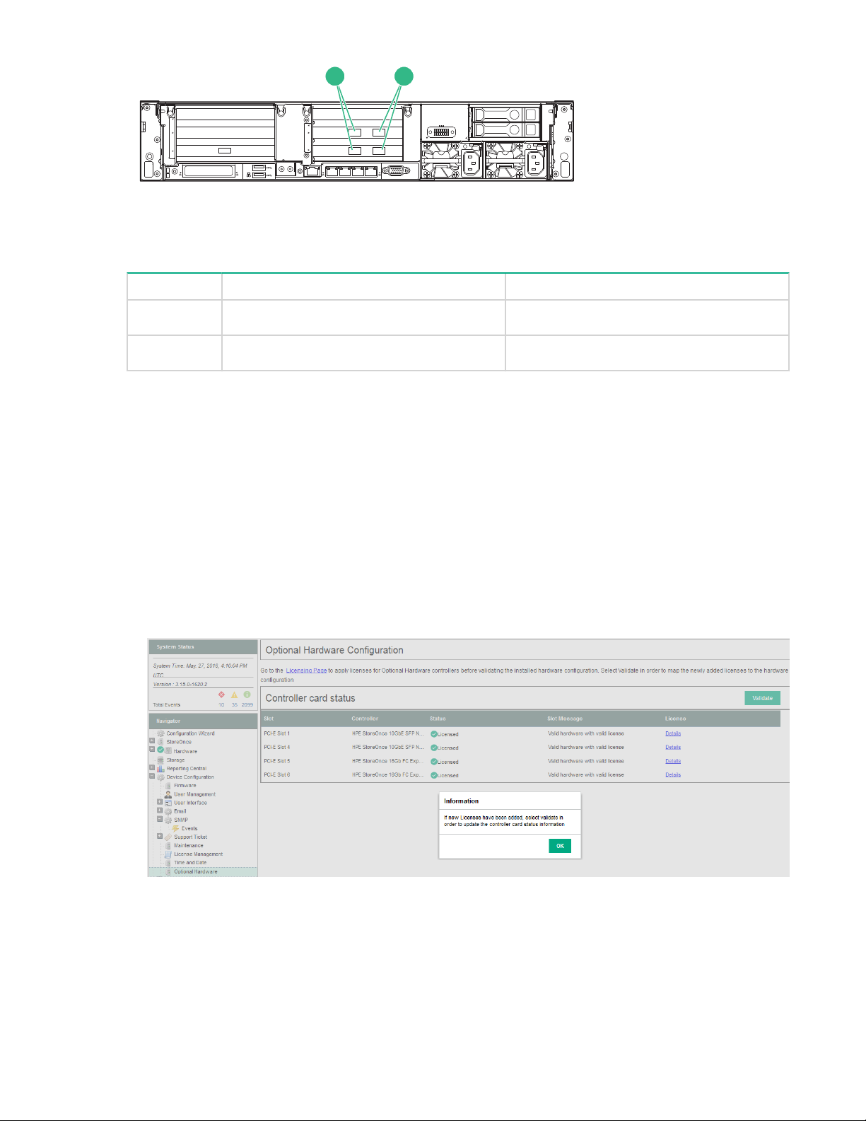
1
2
3
4
1
5
6
4
4
1
iLO
PS2
PS1
21
Figure 21: FC cards
8 Gb FC card 16 Gb FC card
1 Port 1 Port 2
2 Port 2 Port 1
Viewing Optional Hardware configuration
If adding optional hardware after installation, refer to the StoreOnce Optional Hardware Installation and
Configuration Guide for details about installing and licensing the cards.
To view the Optional Hardware options that is currently installed:
Procedure
1. Go to Device Configuration and select Optional Hardware.
2. Click OK at the prompt and look at the Controller card status section.
3. In the following example two 10 GbE SFP network and two 16Gb FC cards have been installed,
licensed and validated.
78 Viewing Optional Hardware configuration
Page 79

Network reference information
More about network configuration
The actual tasks depend upon network environment. They may include:
• Add subnets to the original Port Set on the 1 GbE network.
• Create additional 1 GbE and 10 GbE Port Sets that may be bonded and VLAN enabled.
• Configure IPv4 and IPv6 subnets on Port Sets.
• Add Data in Flight encryption to subnets that are used for replication or StoreOnce Catalyst Copy
between StoreOnce appliances.
Network configuration tasks may be carried out from the StoreOnce GUI or the StoreOnce CLI. A major
benefit of using the StoreOnce GUI, particularly if configuring multiple VLANs, is that you can save the
configuration as you work on it. This guide includes a worked example of using the StoreOnce GUI to
create a network configuration, see
editing and deleting configurations see the StoreOnce System User Guide.
NOTE:
Administrators who have experience of installing and configuring StoreOnce Systems may prefer to use
the StoreOnce CLI commands, particularly net set wizard to configure the network for the first time.
This is described in the HPE StoreOnce CLI Reference Guide.
Complete network configuration on page 55. For information about
Understanding hardware configuration options
1 GbE network connections
All HPE StoreOnce Systems have four 1 GbE network ports. LAN port 1 (eth0) will be connected if you
have followed the instructions in the Start Here installation. The remaining three 1 GbE ports (eth1, eth2
and eth3) are available for further network configuration.
See Hardware overview reference section on page 68 for diagrams showing 1 GbE and 10 GbE port
locations on the rear of the StoreOnce System.
IMPORTANT:
The network configuration may use any available Ethernet port, but one Ethernet port must always
be connected, even if you are using only FC ports to back up and restore data to the StoreOnce
System. This is because the Ethernet connection is required to access the StoreOnce Management
Console remotely and for Catalyst Copy and replication between StoreOnce Systems.
10 GbE network connections
Most HPE StoreOnce Systems also support connection to 10 GbE SFP and 10 GbE-T networks.
Connection requires installation of additional PCIe cards, known as StoreOnce Optional Hardware.
NOTE:
The HPE StoreOnce 3100 System does not support connection to 10 GbE networks.
Network reference information 79
Page 80

• The HPE StoreOnce 3500 Series, HPE StoreOnce 5100 System and HPE StoreOnce 5500 System
support connection to 10 GbE networks.
• For these systems up to four 10 GbE PCIe cards may be installed in the StoreOnce System’s PCIe
slots (in the slot sequence 1, 4, 5 and 6). The number of slots available for 10 GbE connectivity
depends upon whether you are also installing FC cards in Optional Hardware slots.
• If you intend to connect the StoreOnce System to a 10 GbE SFP or Base-T network and have
specified this as part of your original purchase, the 10 GbE cards will already be installed, but you
must install the SFP transceivers for the 10 GbE SFP model. Cables are not supplied.
IMPORTANT:
If you purchase the card(s) after installation, be sure to read the StoreOnce Optional Hardware
Installation and Configuration Guide for instructions on installing and licensing them.
Key network definitions
StoreOnce Systems support both IPv4 and IPv6 address protocols.
• IPv4 is available for backup to all target devices, for replication and StoreOnce Catalyst Copy between
StoreOnce Systems, and for the StoreOnce Management Console.
• IPv6 is supported for backup to StoreOnce Catalyst stores, replication and Catalyst Copy between
StoreOnce Systems, and for the StoreOnce Management Console.
• All systems also support DHCP (v4 and v6).
• Data in flight encryption is intended to be used to secure links between data centers for StoreOnce
Replication or Low Bandwidth Catalyst Copy operations. Using Data In Flight Encryption for direct
backup operations to the StoreOnce appliance over a local network is not supported due to the
performance impact of the encryption. IPSEC is not supported for use on IPv6 subnets
The key points to understand when creating or modifying the configuration are described below.
• Network configuration
The network is defined in a single network configuration with three main components: DNS server
settings, Port Set settings and Subnet settings. There may be up to 16 configurations on any
StoreOnce System, but only one can be active. Once a configuration is activated, it becomes the
current configuration.
• DNS servers
Up to three DNS servers (one primary, and two backup servers if the primary is unavailable) may be
configured for the HPE StoreOnce System. These may have IPv4 and/or IPv6 addresses and apply
across all Port Sets and Subnets defined within the configuration.
• Port sets
A port set defines the physical 1 GbE and 10 GbE Ethernet ports that you intend to connect to your
network. A port set also defines the network port bonding mode, whether VLAN tagging is enabled and
the Frame Size. Mode 1, 4 and 6 network port bonding is supported on sets of 1 GbE and 10 GbE
network ports (but not across 1 GbE and 10 GbE network ports).
At least one Port Set must be configured to support connection to the StoreOnce Management CLI
and GUI. Further Port Sets may be defined, according to the number and type of physical ports still
available and how they are bonded.
80 Key network definitions
Page 81

Each Port Set will have at least one Subnet.
• Subnets
Subnets define the network paths used by clients to access the HPE StoreOnce System for Backup
and Management, and the network paths that are used for StoreOnce Catalyst Copy and Replication
between HPE StoreOnce Systems. This is where the IP protocol and IP address details are defined for
the subnet and the VLAN tag, if appropriate.
◦ If the Port Set is not VLAN enabled, it may be configured with one Data Subnet that uses the IPv4
protocol and one Data Subnet that uses the IPv6 protocol. (This configuration is sometimes
referred to as a dual stack configuration.)
◦ VLAN tagging enables more subnets to be accessed without extra NIC host bus adapters. If the
Port Set is VLAN enabled, multiple virtual subnets (IPv4 and IPv6), up to a maximum of 128 for the
whole system, may be attached to a single Port Set. If VLAN is enabled, a Port Set cannot use
bonding mode 6.
◦ Data in flight encryption is available and is applied at Subnet level. It is intended to be used to
secure links between data centers for StoreOnce VTL or NAS Replication or Low Bandwidth
Catalyst Copy operations.
IMPORTANT:
Using Data In Flight Encryption for direct backup operations to the StoreOnce appliance over
a local network is not supported due to the performance impact of the encryption. IPSEC is
not supported for use on IPv6 subnets.
Network bonding modes
Each set of network ports on the appliance can be configured either on separate Subnets or in a bond
with each other (1 GbE and 10 GbE ports cannot be bonded together).
Three bonding modes are supported:
• Mode 1 (Active/Backup)
This is the most simple bonding mode; it allows network traffic via one active port only and requires no
specific extra switch configuration. It is recommended for simple network connections, if the active
network link fails then traffic moves to the backup port.
• Mode 4 (IEEE 802.3ad Dynamic Link Aggregation)
This bonding mode is also known as LACP and requires a special external switch configuration. It
provides a link aggregation solution, increasing the bond physical bandwidth, but only works if all the
ports in the bond are connected to one switch or switches joined by an interswitch link. It is
recommended when:
◦ The customer wants to increase throughput to the StoreOnce appliance.
◦ Trunks between switches on the customer network already use LACP mode.
Network bonding modes 81
Page 82

The LACP protocol only works when it is configured on both the network switch and StoreOnce end of
the connection. Please refer to your switch documentation for information on LACP configuration.
• Mode 6 (Active Load Balancing)
This mode provides a load balance solution. It does not require specific external switch configuration
but does require the switch to allow ARP negotiation. It can be used in a 2–switch configuration.
This configuration is generally recommended for backup data performance and also for resiliency of
both data and management network connectivity. However, in some environments ARP packet
negotiation may be disabled within the network infrastructure, so this mode may not be appropriate.
NOTE:
When using bonded ports the full performance of bonded links are only realized if multiple host servers
are providing data, otherwise data will still use only one network path from the single server.
VLAN guidelines with StoreOnce systems
There is a fixed number of available physical NIC ports on the StoreOnce System, defined by the number
of 1 GbE ports plus 10 GbE ports, therefore there is a limit on the number of physical Subnets to which
the StoreOnce System can be directly connected. If your network requires more Subnets than this—for
example, twenty—the network administrator can define 20 VLANs, each with its own Subnet and,
typically, use a 10 GbE bonded link to the StoreOnce System as a trunk.
To do this, the network administrator sets up the switches with the necessary VLANs and identifies 20
tags. (The tag values can be any integer between range 2-4094.) The ports on the network switch to
which the StoreOnce System connects must be trunked and tagged. Then using the StoreOnce CLI or
GUI, the HPE StoreOnce administrator modifies the network configuration by first defining the Port Set for
the physical 10 GbE link and making it VLAN enabled, and then configuring each of the twenty VLAN
Subnets to use that Port Set.
The following VLAN guidelines apply:
• The user can configure up to a total of 128different VLAN Subnets on each StoreOnce System; the
VLAN Subnets may be consecutive or non-consecutive.
• The user can configure all VLAN Subnets on one Port Set or divide the VLAN Subnets over multiple
Port Sets.
• It is not permitted to configure VLAN Subnets on a Port Set that uses Mode 6 network bonding.
• Each VLAN tag interface is configured using the VLAN ID index, which is the same as the switch
VLAN ID number and must be an integer from 2 to 4094.
• Each VLAN tag interface can be configured for use with one IPv4 and one IPv6 subnet.
For example, if a VLAN tag ID was configured for use with ports eth 0 and eth1 on IPv4, it can also be
configured for use on IPv6 with that Port Set but it cannot be used with any other Port Set.
• The user can add/delete/modify the VLAN network configuration without interrupting non-affected
network configuration on the appliance.
• VLAN tagging does not increase bandwidth because the bandwidth is bound by the physical speed of
the Port Set. The number of open streams is bound by the specification for the StoreOnce appliance.
82 VLAN guidelines with StoreOnce systems
Page 83

• StoreOnce monitoring is on the physical Port Set, not on each VLAN Subnet.
• VLAN tagging is not a multi-tenancy solution. Once configured, all StoreOnce services can bind / listen
to all VLAN Subnets. For example the NAS shares are available on all configured Subnets, and
permissions are required to regulate access to shares.
Network reference information 83
Page 84

Fibre Channel with StoreOnce Systems
Fibre Channel hardware requirements
The Fibre Channel hardware option is not supported on the HPE StoreOnce 3100 System.
All other StoreOnce Systems described in this guide support data backup to StoreOnce Catalyst and VTL
devices via Fibre Channel.
If you intend to connect the HPE StoreOnce System to a SAN, you must purchase and install one or more
FC cards in the PCIe slots. SFP transceivers are supplied with the FC card.
If you have specified this as part of your original purchase, the FC cards will already be installed, but you
must install the SFP transceivers before connecting the HPE StoreOnce System to the SAN. Cables are
not supplied.
IMPORTANT:
If you purchase the card(s) after installation, be sure to read the StoreOnce System Optional
Hardware Installation and Configuration Guide for details about installing and licensing the cards.
More information
Hardware overview reference section on page 68
Supported Fibre Channel connections
• The StoreOnce System supports both switched fabric and direct attach private loop topologies.
A switched fabric topology utilizes one or more fabric switches to provide a flexible configuration
between several Fibre Channel hosts and Fibre Channel targets such as StoreOnce Systems.
• Switched fabric configurations are implemented with Fibre Channel switches. Switches may be
cascaded or meshed together to form larger fabrics.
• The preferred topology for the StoreOnce System is switched fabric using NPIV (N_Port ID
Virtualisation).
NOTE:
Please refer to http://www.hpe.com/info/ebs for the latest information about compatibility.
Zoning
Zoning is only required if a switched fabric topology is used.
Due to complexities in multi-hosting tape devices on SANs, it is best to make use of zoning tools to help
keep the backup/restore environment simple and less susceptible to the effects of changing or
problematic SANs.
Zoning provides a way for servers, disk arrays, and tape libraries to only see what hosts and targets they
need to see and use. The benefits of zoning include but are not limited to:
• Limiting unnecessary discoveries on the StoreOnce System.
• Reducing stress on the StoreOnce System and its library devices by polling agents.
84 Fibre Channel with StoreOnce Systems
Page 85

• Reducing the time it takes to debug and resolve anomalies in the backup/restore environment.
• Reducing the potential for conflict with untested third-party products.
Zoning may not be necessary for small or simple configurations. Typically the bigger the SAN is, the more
zoning is needed. HPE recommends the following for determining how and when to use zoning.
• Small fabric (16 ports or less)—may not need zoning.
• Small to medium fabric (16 - 128 ports)—use host-centric zoning. Host-centric zoning is implemented
by creating a specific zone for each server or host, and adding only those storage elements to be used
by that host. Host-centric zoning prevents a server from detecting any other devices on the SAN or
including other servers, and it simplifies the device discovery process.
• Disk and tape on the same pair of HBAs is supported along with the coexistence of array multipath
software (no multipath to tape or library devices on the StoreOnce System, but coexistence of the
multipath software and tape devices).
• Large fabric (128 ports or more)—use host-centric zoning and split disk and tape targets. Splitting disk
and tape targets into separate zones prevents the StoreOnce System from discovering unnecessary
disk controllers. For optimal performance, where practical, dedicate HBAs for disk and tape.
NOTE:
Overlapping zones are supported.
NOTE:
The HP Brocade SAN Switches support NPIV natively but the Cisco SAN Switches require that it be
turned on for each port used.
Configuring Fibre Channel
For use with StoreOnce Catalyst stores
The StoreOnce Catalyst — Fibre Channel Settings tab is the main page for configuring StoreOnce
Catalyst over Fibre Channel. Configuration settings are summarized below. See the StoreOnce System
User Guide for detailed instructions with screenshot examples.
• In the Devices section, locate the World Wide Node Nameand World Wide Port Name information
for each port on the StoreOnce System. This is the information that you need to zone the client with
the StoreOnce System.
• Also look at the Identifier Name in the top section of the screen. This is the FC address of the
StoreOnce System and is used to identify the StoreOnce System in the backup application. It is in the
format CoFC-<device-id>; if preferred, you may provide an Identifier Alias, which will be easier to
identify from the backup application.
• The Target Ports section in the center of the screen is identical to the settings that you can configure
for VTL target devices over FC. The default values are recommended, but you may edit Speed and
Topology.
Configuring Fibre Channel 85
Page 86

NOTE:
These Fibre Channel settings apply to the whole appliance and can also be edited in the StoreOnce
VTL section of the GUI, if you are backing up to StoreOnce VTL library target devices over Fibre
Channel. Port Speed or Topology settings, defined on either page, apply to all target devices being
backed up over Fibre Channel.
• In the Devices section locate the Number of Logins and Devices per Initiator Portfor each port.
These values determine the number of concurrent backup and restore connections allowed on each
FC port on the StoreOnce System.
◦ The Number of Logins defines the number of client-side ports that are zoned to be able to
connect to that port on the StoreOnce System. This cannot be edited.
◦ The Devices per Initiator Portvalue determines the number of backup and restore connections
that are allowed — for each client login — to that port on the StoreOnce System. This value should
be increased if multiple concurrent backup streams are required. Note that the maximum allowed is
64.
NOTE:
Once the client has Fibre Channel zoned with the StoreOnce appliance, there are a number of
considerations for each operating system. See the HPE StoreOnce User Guide for more details.
For use with VTL libraries
Configuration settings are summarized below. See the StoreOnce System User Guide for detailed
instructions with screenshot examples.
There are three StoreOnce GUI screens that relate to FC with VTL.
• If required, the administrator may configure the port speed or topology from the VTL-Fibre Channel
Settings tab. The default settings are recommended.
These Fibre Channel settings apply to the whole appliance and can also be edited in the StoreOnce
Catalyst section of the GUI, if you are backing up to StoreOnce Catalyst target devices over Fibre
Channel. Port Speed or Topology settings, defined on either page, apply to all target devices being
backed up over Fibre Channel. Therefore, any changes here will also apply to StoreOnce Catalyst
target devices over Fibre Channel and vice versa.
NOTE:
Changing the port speed will make the StoreOnce System appear as down. Refresh the VTL
Configuration page to update the status. This will also update the Fibre Channel Settings tab.
• When the user creates a library, using the VTL-Libraries-Create function, they specify which FC ports
it will use.
• The world wide names for the ports can then be found on the VTL-Libraries-Interface Information
tab.
86 For use with VTL libraries
Page 87

Support and other resources
Accessing Hewlett Packard Enterprise Support
• For live assistance, go to the Contact Hewlett Packard Enterprise Worldwide website:
http://www.hpe.com/assistance
• To access documentation and support services, go to the Hewlett Packard Enterprise Support Center
website:
http://www.hpe.com/support/hpesc
Information to collect
• Technical support registration number (if applicable)
• Product name, model or version, and serial number
• Operating system name and version
• Firmware version
• Error messages
• Product-specific reports and logs
• Add-on products or components
• Third-party products or components
Accessing updates
• Some software products provide a mechanism for accessing software updates through the product
interface. Review your product documentation to identify the recommended software update method.
• To download product updates:
Hewlett Packard Enterprise Support Center
www.hpe.com/support/hpesc
Hewlett Packard Enterprise Support Center: Software downloads
www.hpe.com/support/downloads
Software Depot
www.hpe.com/support/softwaredepot
• To subscribe to eNewsletters and alerts:
www.hpe.com/support/e-updates
• To view and update your entitlements, and to link your contracts and warranties with your profile, go to
the Hewlett Packard Enterprise Support Center More Information on Access to Support Materials
page:
Support and other resources 87
Page 88

www.hpe.com/support/AccessToSupportMaterials
IMPORTANT:
Access to some updates might require product entitlement when accessed through the Hewlett
Packard Enterprise Support Center. You must have an HP Passport set up with relevant
entitlements.
Customer self repair
Hewlett Packard Enterprise customer self repair (CSR) programs allow you to repair your product. If a
CSR part needs to be replaced, it will be shipped directly to you so that you can install it at your
convenience. Some parts do not qualify for CSR. Your Hewlett Packard Enterprise authorized service
provider will determine whether a repair can be accomplished by CSR.
For more information about CSR, contact your local service provider or go to the CSR website:
http://www.hpe.com/support/selfrepair
Remote support
Remote support is available with supported devices as part of your warranty or contractual support
agreement. It provides intelligent event diagnosis, and automatic, secure submission of hardware event
notifications to Hewlett Packard Enterprise, which will initiate a fast and accurate resolution based on your
product's service level. Hewlett Packard Enterprise strongly recommends that you register your device for
remote support.
If your product includes additional remote support details, use search to locate that information.
Remote support and Proactive Care information
HPE Get Connected
www.hpe.com/services/getconnected
HPE Proactive Care services
www.hpe.com/services/proactivecare
HPE Proactive Care service: Supported products list
www.hpe.com/services/proactivecaresupportedproducts
HPE Proactive Care advanced service: Supported products list
www.hpe.com/services/proactivecareadvancedsupportedproducts
Proactive Care customer information
Proactive Care central
www.hpe.com/services/proactivecarecentral
Proactive Care service activation
www.hpe.com/services/proactivecarecentralgetstarted
Warranty information
To view the warranty for your product, see the Safety and Compliance Information for Server, Storage,
Power, Networking, and Rack Products document, available at the Hewlett Packard Enterprise Support
Center:
www.hpe.com/support/Safety-Compliance-EnterpriseProducts
88 Customer self repair
Page 89

Additional warranty information
HPE ProLiant and x86 Servers and Options
www.hpe.com/support/ProLiantServers-Warranties
HPE Enterprise Servers
www.hpe.com/support/EnterpriseServers-Warranties
HPE Storage Products
www.hpe.com/support/Storage-Warranties
HPE Networking Products
www.hpe.com/support/Networking-Warranties
Regulatory information
To view the regulatory information for your product, view the Safety and Compliance Information for
Server, Storage, Power, Networking, and Rack Products, available at the Hewlett Packard Enterprise
Support Center:
www.hpe.com/support/Safety-Compliance-EnterpriseProducts
Additional regulatory information
Hewlett Packard Enterprise is committed to providing our customers with information about the chemical
substances in our products as needed to comply with legal requirements such as REACH (Regulation EC
No 1907/2006 of the European Parliament and the Council). A chemical information report for this product
can be found at:
www.hpe.com/info/reach
For Hewlett Packard Enterprise product environmental and safety information and compliance data,
including RoHS and REACH, see:
www.hpe.com/info/ecodata
For Hewlett Packard Enterprise environmental information, including company programs, product
recycling, and energy efficiency, see:
www.hpe.com/info/environment
Documentation feedback
Hewlett Packard Enterprise is committed to providing documentation that meets your needs. To help us
improve the documentation, send any errors, suggestions, or comments to Documentation Feedback
(docsfeedback@hpe.com). When submitting your feedback, include the document title, part number,
edition, and publication date located on the front cover of the document. For online help content, include
the product name, product version, help edition, and publication date located on the legal notices page.
Regulatory information 89
Page 90

Additional regulatory information
Belarus Kazakhstan Russia marking
Manufacturer and Local Representative Information
Manufacturer information:
Hewlett Packard Enterprise Company, 3000 Hanover Street, Palo Alto, CA 94304 U.S.
Local representative information Russian:
• Russia:
• Belarus:
• Kazakhstan:
Local representative information Kazakh:
• Russia:
• Belarus:
• Kazakhstan:
Manufacturing date:
The manufacturing date is defined by the serial number.
90 Additional regulatory information
Page 91
CCSYWWZZZZ (serial number format for this product)
Valid date formats include:
• YWW, where Y indicates the year counting from within each new decade, with 2000 as the starting
point; for example, 238: 2 for 2002 and 38 for the week of September 9. In addition, 2010 is indicated
by 0, 2011 by 1, 2012 by 2, 2013 by 3, and so forth.
• YYWW, where YY indicates the year, using a base year of 2000; for example, 0238: 02 for 2002 and
38 for the week of September 9.
Turkey RoHS material content declaration
Ukraine RoHS material content declaration
Turkey RoHS material content declaration 91
 Loading...