

HP StoreOnce 2700, StoreOnce 4500, StoreOnce 4700, StoreOnce 2900 Installation And Configuration Manual
Page 1

HP StoreOnce
2700, 2900, 4500 and 4700 Backup
Installation and Configuration Guide
Abstract
This document describes how to install and configure HP StoreOnce 4700, 4500, 2900 and 2700 Backup systems. These
systems are also sometimes referred to as single-node StoreOnce products and they were introduced with StoreOnce software
version 3.9.0 (or 3.12.0 for HP StoreOnce 2900).
HP Part Number: BB877-90938
Published: August 2015
Edition: 5
Page 2

© Copyright 2013–2015 Hewlett-Packard Development Company, L.P.
Confidential computer software. Valid license from HP required for possession, use or copying. Consistent with FAR 12.211 and 12.212, Commercial
Computer Software, Computer Software Documentation, and Technical Data for Commercial Items are licensed to the U.S. Government under
vendor's standard commercial license.
The information contained herein is subject to change without notice. The only warranties for HP products and services are set forth in the express
warranty statements accompanying such products and services. Nothing herein should be construed as constituting an additional warranty. HP shall
not be liable for technical or editorial errors or omissions contained herein.
WARRANTY STATEMENT: To obtain a copy of the warranty for this product, see the warranty information website:
http://www.hp.com/go/storagewarranty
Linear Tape-Open, LTO, LTO Logo, Ultrium and Ultrium Logo are trademarks of Quantum Corp, HP and IBM in the US, other countries or both.
Windows is a trademark of the Microsoft group of companies.
Revision History
October 2013Revision 1
This is the first edition of the guide for HP StoreOnce 2700, 4500 and 4700 Backup systems, issued with the 3.9.0 or later version of HP StoreOnce
software.
June 2014Revision 2
This is the second edition of the guide, issued with the 3.11.0 version of HP StoreOnce software.
December 2014Revision 3
This is the third edition of the guide, issued with the 3.12.0 version of HP StoreOnce software.
March 2015Revision 4
This is the fourth edition of the guide to include HP StoreOnce 2900 Backup and web browser information. The part number has not been updated
because edition 3 was not released to hp.com.
August 2015Revision 5
This is the fifth edition of the guide with updates to networking and remote support for StoreOnce software version 3.13.x..
Page 3

Contents
1 Before you start..........................................................................................7
Introduction..............................................................................................................................7
HP StoreOnce 2700, 2900, 4500 and 4700 models....................................................................7
Software and hardware requirements..........................................................................................8
Supported Ethernet configurations..........................................................................................8
iLO 4 functionality................................................................................................................9
Supported Fibre Channel connections.....................................................................................9
Software requirements........................................................................................................10
Recommended web browser settings.........................................................................................10
2 Installing and cabling the HP StoreOnce Backup system................................11
Installing the rail kit.................................................................................................................11
Mounting the HP StoreOnce Backup system................................................................................11
Attaching SFPs, StoreOnce 2900, 4500 and 4700 only..............................................................12
HP StoreOnce 4700 Backup................................................................................................13
HP StoreOnce 2900 and 4500 Backup................................................................................14
Connecting the hardware........................................................................................................15
Connecting the HP StoreOnce 4700 Backup system................................................................15
Connecting the first storage enclosure at installation...........................................................16
Connecting the HP StoreOnce 4500 Backup system...............................................................17
Connecting the HP StoreOnce 2900 Backup system...............................................................17
Connecting the HP StoreOnce 2700 Backup system................................................................18
Attaching the security bezel.................................................................................................18
Connecting to the expansion enclosure (HP StoreOnce 4500 and 4700).......................................18
Installing expansion enclosures with the HP StoreOnce 4700...................................................19
Installing expansion enclosures with the HP StoreOnce 4500...................................................20
Adding disks for capacity expansion (StoreOnce 2900 only).......................................................22
3 Powering on and managing the StoreOnce Management system....................24
Powering on expansion shelves, HP 4500 and 4700 only............................................................24
Powering on the HP StoreOnce Backup system............................................................................24
Discovering the HP StoreOnce Backup system on the network.......................................................25
Accessing the StoreOnce Management Console.........................................................................25
The StoreOnce CLI.............................................................................................................25
The StoreOnce GUI............................................................................................................26
User roles and accounts .........................................................................................................26
Password best practices...........................................................................................................27
User account and password requirements..............................................................................27
4 Configuration using the system set config wizard..........................................28
System configuration using system set config command................................................................28
Configure network.............................................................................................................28
Configure Time..................................................................................................................28
Configure Licenses.............................................................................................................29
Verify Hardware health.......................................................................................................29
Finish Configuration (and reboot).........................................................................................29
5 Network configuration, understanding the StoreOnce networking concepts......30
Network configuration basics...................................................................................................30
Network configuration components......................................................................................30
Port numbering for hardware products..................................................................................32
Network bonding modes....................................................................................................33
VLAN Subnets with HP StoreOnce Backup............................................................................33
Contents 3
Page 4

VLAN guidelines...........................................................................................................34
Example network environment.........................................................................................34
Network configuration guidelines.............................................................................................35
Deciding whether to use the StoreOnce CLI or the StoreOnce GUI................................................36
At installation....................................................................................................................36
After installation................................................................................................................36
Physical ports and IP addresses................................................................................................36
6 Network configuration, how to use StoreOnce CLI commands........................38
Identifying available ports on the StoreOnce CLI.........................................................................38
Identifying network ports available.......................................................................................38
Network bonding combinations...........................................................................................39
Before running net set wizard...................................................................................................39
Network configuration using net set wizard................................................................................41
Modifying the current network configuration...............................................................................48
Best practice.....................................................................................................................48
To add Data in Flight Encryption..........................................................................................49
License requirements......................................................................................................50
Configuring the StoreOnce Backup system........................................................................50
Encryption with replication.............................................................................................51
Configuring the backup media server...............................................................................51
Troubleshooting............................................................................................................51
7 Network configuration, how to use the StoreOnce GUI..................................53
To add a custom configuration.................................................................................................53
To edit a custom configuration..................................................................................................57
To add a VLAN–enabled Port Set and VLAN Subnet..............................................................57
To write protect or un-protect a configuration.........................................................................58
8 Completing the installation........................................................................59
Setting up time and date.........................................................................................................59
Configuring licenses................................................................................................................60
Licensing requirements for StoreOnce hardware products........................................................60
Applying the Instant On license...........................................................................................60
To apply a full license.........................................................................................................61
Expanding storage.................................................................................................................62
Accessing the StoreOnce Backup system over SFTP.....................................................................63
Accessing the StoreOnce folders..........................................................................................64
Software update process.........................................................................................................64
Upgrading BIOS or hardware firmware components....................................................................64
Configuring Remote Support....................................................................................................66
Before configuring Remote Support.......................................................................................66
General procedure for setting up Remote Support on the HP StoreOnce Management GUI..........67
Locating warranty information.............................................................................................68
Warranty details - HP 4700.................................................................................................69
Warranty details - HP 4500................................................................................................70
Warranty details — HP 2900..............................................................................................71
Warranty details - HP 2700.................................................................................................71
Configuring SNMP.................................................................................................................72
Network Management systems and MIBs..............................................................................72
Saving the configuration..........................................................................................................72
Restoring the configurations.................................................................................................73
Saving the encryption keystore..................................................................................................73
Managing and resetting the password for the HPresetpassword account........................................73
To change the password for the HPresetpassword account.......................................................73
To reset the password for the local Admin user to default.........................................................74
4 Contents
Page 5

9 Fibre Channel installation and configuration................................................75
Fibre Channel connection........................................................................................................75
StoreOnce Catalyst over Fibre Channel......................................................................................75
Fibre Channel Settings tab..................................................................................................75
Fibre Channel with VTL............................................................................................................77
Creating a FC VTL library...................................................................................................78
Drive port assignment for StoreOnce Backup systems..............................................................78
Zoning..................................................................................................................................79
10 Configuring backup servers to work with HP StoreOnce...............................80
Configuring media servers to use StoreOnce Catalyst..................................................................80
Configuring Data in Flight encryption on Windows media servers.................................................80
Driver installation (optional, VTL only)........................................................................................89
iSCSI Initiator (optional, VTL only).............................................................................................90
Manual iSCSI initiator installation........................................................................................91
The iSCSI Initiator and Authentication...................................................................................91
The Microsoft iSCSI Initiator ................................................................................................91
11 Understanding LEDs..............................................................................100
Front view of the HP StoreOnce 4700 Backup system.................................................................101
Capacity upgrade kit LEDs.....................................................................................................102
Front view of the HP StoreOnce 4500 Backup system................................................................103
Front view of the HP StoreOnce 2900 Backup system................................................................104
Front view of the HP StoreOnce 2700 Backup system.................................................................105
Hot-plug drive LEDs...............................................................................................................106
Server units.....................................................................................................................106
Expansion shelves............................................................................................................107
1 Gbit ethernet port LEDs.......................................................................................................107
10 Gbit ethernet card LEDs....................................................................................................107
Fibre Channel card LEDs.......................................................................................................108
12 Troubleshooting....................................................................................109
Connecting to the network.....................................................................................................109
Connecting to the StoreOnce Backup system from the backup application....................................110
Performance.........................................................................................................................110
Power up and power off .......................................................................................................111
Powering up servers.........................................................................................................111
Powering off....................................................................................................................111
Rebooting the system........................................................................................................111
Power On/Off Problems...................................................................................................111
Licensing problems...............................................................................................................112
Instant On license expires.................................................................................................112
Problems expanding storage..................................................................................................112
Discover storage fails.......................................................................................................112
Add storage fails.............................................................................................................112
Cannot connect to a NAS share.............................................................................................112
NAS shares and IPv6............................................................................................................112
Cannot access a storage shelf ...............................................................................................113
13 More networking examples....................................................................114
Example 1...........................................................................................................................114
Example 2...........................................................................................................................115
StoreOnce GUI Status page..............................................................................................117
Example 3...........................................................................................................................117
About this guide........................................................................................120
Intended audience................................................................................................................120
Contents 5
Page 6

Related documentation..........................................................................................................120
Document conventions and symbols........................................................................................120
HP technical support.............................................................................................................121
Customer self repair..............................................................................................................121
Registering your HP StoreOnce Backup system..........................................................................121
Subscription service..............................................................................................................121
HP Insight Remote Support.....................................................................................................121
HP websites.........................................................................................................................122
Documentation feedback.......................................................................................................122
A Regulatory information............................................................................123
Belarus Kazakhstan Russia marking.........................................................................................123
Turkey RoHS material content declaration.................................................................................124
Ukraine RoHS material content declaration..............................................................................124
Warranty information............................................................................................................124
Index.......................................................................................................125
6 Contents
Page 7

1 Before you start
In this chapter:
• Introduction (page 7)
• HP StoreOnce Backup models (page 7)
• Software and hardware requirements (page 8)
• Supported Ethernet configurations (page 8)
• Supported Fibre Channel connections (page 9)
• Web browser settings (page 10)
Introduction
The HP StoreOnce Backup system is a disk-based storage appliance for backing up network media
servers or PCs to target devices on the appliance. These devices are configured as either
Network-Attached Storage (NAS), Catalyst Stores or Virtual Tape Library (VTL) targets for backup
applications.
This guide describes how to install and carry out the initial configuration of your HP StoreOnce
Backup system. The following documents are also available at http://www.hp.com/go/storage/
docs and http://www.hp.com/support/ (search on Product Name and then select the Product
Manuals link):
• HP StoreOnce Installation posters: Installation posters are available for each product family
and describe how to quickly install the product by connecting LAN Port 1 to a 1 Gbit ethernet
network.
• HP StoreOnce Backup system User Guide: This guide contains detailed information about the
StoreOnce Graphical User Interface (GUI) and troubleshooting information, including replacing
failed or failing hard disks.
• HP StoreOnce Backup system CLI Reference Guide: This is the full reference guide for the
StoreOnce Command Line Interface (CLI).
• HP StoreOnce Backup system Linux and UNIX Configuration Guide: This guide explains how
to configure HP StoreOnce Backup systems with supported Linux and UNIX operating systems.
• HP StoreOnce Backup 4500/4700 (24TB) and 4500 (48TB) Capacity Upgrade Guide: This
guide explains how to connect additional storage shelves to HP StoreOnce 4500 and 4700
Backup systems.
• HP StoreOnce Backup 2900 (24TB) Capacity Upgrade Guide: This guide explains how to
connect additional hard disks to HP StoreOnce 2900 Backup systems.
HP StoreOnce 2700, 2900, 4500 and 4700 models
The following products belong to the HP StoreOnce G3 Backup system family; they are also
sometimes referred to as single-node StoreOnce models, to differentiate them from the HP StoreOnce
B6200 and 6500 Backup systems which are multi-node StoreOnce products. (This node distinction
is important when configuring replication and Catalyst copy jobs and understanding target and
source IP addresses.) G3 indicates that the HP StoreOnce Backup systems will be running v3.x.x
StoreOnce software.
Introduction 7
Page 8

Table 1 StoreOnce 2700, 2900, 4500 and 4700 models
Storage expansionPortsInterfaces supportedDescriptionProduct model
Not supported4 x 1 Gbit ethernet
ports
iSCSI onlyA single server with
four 2TB hot-plug disks
HP StoreOnce 2700
8TB Backup , BB877A
One 6–disk expansion
kit, BB911A
4 x 1 Gbit ethernet
ports
iSCSI onlyA single server with
six 4TB hot-plug disks
HP StoreOnce 2900
24TB Backup,
BB910A
2 x 10 Gbit ethernet
ports
Up to three expansion
enclosures, which may
4 x 1 Gbit ethernet
ports
iSCSI and FCA single server with
twelve 2TB hot-plug
disks
HP StoreOnce 4500
24TB Backup,
BB878A be any combination of
the following:
2 x 10 Gbit ethernet
ports
1. 12–disk 24TB
expansion
enclosure, BB881A
2 x FC ports
2. 12–disk 48TB
expansion
enclosure, BB882A
Up to seven 12–disk
expansion enclosures,
BB881A
4 x 1 Gbit ethernet
ports
2 x 10 Gbit ethernet
ports
iSCSI and FCA head server unit
with two 1TB disks
and a pre-configured
storage array with
twelve 2TB disks
HP StoreOnce 4700
24TB Backup,
BB879A
4 x FC ports
Software and hardware requirements
Refer to http://www.hp.com/go/ebs for the latest connectivity and compatibility information.
Supported Ethernet configurations
The HP StoreOnce Backup system supports a wide range of network configurations. The following
list provides an overview of configuration details. See Network configuration, understanding the
concepts (page 30) for more details about network support and configuring the network. Also refer
to the latest release notes to find out if there are any configuration combinations that require specific
attention.
• An Ethernet connection is required for backing up to iSCSI VTL devices and NAS shares, for
replication and StoreOnce Catalyst Copy activities, and for all StoreOnce management tasks.
It is also required if you wish to backup StoreOnce Catalyst stores across ethernet.
• The HP StoreOnce Backup system supports IPv4 and IPv6. IPv4 is available for backup to all
target devices and for appliance management; IPv6 is supported for backup to StoreOnce
Catalyst stores, replication and Catalyst Copy, and for appliance management. It cannot be
used for backup to VTL or NAS shares.
NOTE: IPv6 is not supported on the iSCSI data path for VTL nor the NFS/CIFS data path
for NAS Shares.
• The HP StoreOnce Backup system may be connected to a virtual LAN and supports VLAN
tagging.
• DHCP and static IP addressing are supported.
NOTE: If DHCP is used, it is recommended that once an IP address has been assigned, the
Network Administrator should permanently associate that IP address with the StoreOnce
Backup system. This association prevents the IP address of the device changing after reboots.
8 Before you start
Page 9

• All StoreOnce Backup systems have four 1 Gbit ethernet ports. HP StoreOnce 2900, 4500
and 4700 Backup systems have two additional 10 Gbit ethernet ports.
• Mode 1, 4 and 6 network port bonding is supported on sets of 1 Gbit and 10 Gbit ethernet
ports (but not across 1 Gbit and 10 Gbit ethernet ports).
• Networking parameters are contained within a network configuration. For ease of installation,
a default configuration is initially applied to the StoreOnce Backup system. As long as LAN
port 1 of the appliance is connected to a DHCP–enabled 1 Gbit ethernet network switch, the
HP StoreOnce Backup system will be active on the network immediately after installation.
You can continue to use the default configuration or create and activate an additional
configuration that is tailored to your exact networking requirements using either the StoreOnce
CLI or the StoreOnce GUI.
NOTE: 100 Base-T Ethernet will limit performance.
• Users without a DHCP-enabled 1 Gbit ethernet network must create and activate a network
configuration before the StoreOnce Backup system can become active on the network. This
network configuration may use any available Ethernet port, but one Ethernet port must always
be connected, even if you are using only the FC ports to back up and restore data to the HP
StoreOnce Backup system. The port connection is required because the network is used to
access the StoreOnce Management Console remotely and for replication.
TIP: The recommended way to create an initial network configuration to support static IP
addressing is to run the StoreOnce CLI wizard, net set wizard, as described in Network
configuration, how to use StoreOnce CLI commands (page 38).
iLO 4 functionality
HP StoreOnce backup appliances are built on HP Proliant server hardware and use the embedded
HP Integrated Lights-Out 4 (iLO 4) management technology. iLO enables secure remote monitoring
and console access via a web browser. All HP StoreOnce Backup systems described in this guide
are supplied with an iLO password that should be changed after installation and stored safely
offsite with other passwords.
iLO is not required for daily management of the StoreOnce appliance but is useful in a lights-out
data center situation. iLO is also useful for diagnosing hardware failures that prevent access to the
appliance through the primary StoreOnce GUI or remote StoreOnce CLI interface.
NOTE: See also Password best practices (page 27).
Supported Fibre Channel connections
NOTE: Fibre Channel is not supported on the HP StoreOnce 2700 or 2900 Backup systems.
For a more detailed discussion of Fibre Channel configuration options, see also Fibre channel
installation and configuration (page 75).
• When connecting to a Fibre Channel network, the HP StoreOnce Backup system is supplied
with the correct FC card pre-installed. Cables are not supplied.
• The number of FC ports available depends upon the HP StoreOnce model.
All models that support FC have two FC ports on the FC card; the HP StoreOnce 4700 has
two FC cards and, therefore, four FC ports are available.
Software and hardware requirements 9
Page 10

• The HP StoreOnce Backup system supports both switched fabric and direct attach private loop
topologies.
A switched fabric topology utilizes one or more fabric switches to provide a flexible
configuration between several Fibre Channel hosts and Fibre Channel targets such as HP
StoreOnce Backup systems.
• Switched fabric configurations are implemented with Fibre Channel switches. Switches may
be cascaded or meshed together to form larger fabrics.
• The preferred topology for the HP StoreOnce Backup system is switched fabric using NPIV
(N_Port ID Virtualisation).
NOTE: Please refer to http://www.hp.com/go/ebs for the latest information about compatibility.
Software requirements
• Backup and restore to Virtual Tape Library targets requires software that supports tape libraries.
This software resides on a backup media server, not the HP StoreOnce Backup system.
StoreOnce target devices may be used with major backup applications from HP, Symantec,
EMC, Computer Associates and others.
• For supported Symantec backup products, the HP StoreOnce Catalyst OST plug-in application
is required on each backup application media server that will use the StoreOnce Catalyst
functionality. The minimum OST plug-in version is 2.1. To use StoreOnce over FC, OST plug-in
version 3.0 is required.
Refer to http://www.hp.com/go/ebs for the latest compatibility information.
Recommended web browser settings
The web browser used to communicate with the HP StoreOnce Backup system requires Active
Scripting or JavaScript enabled. Without these scripts enabled, some browser buttons may not
display.
With StoreOnce software version 3.12.0 and later, the StoreOnce Management GUI is supported
on the following web browsers:
• Internet Explorer 9, 10 and 11 (note that Internet Explorer 8 is not supported and some
StoreOnce features will not work)
• Mozilla FireFox v22 and above and Firefox ESR24
Please refer to http://www.hp.com/go/ebs for the latest information about which browser versions
are supported.
IMPORTANT: The HP StoreOnce Backup system software will not allow access if security is
disabled on the browser.
10 Before you start
Page 11

2 Installing and cabling the HP StoreOnce Backup system
In this chapter:
• Installing the rail kit (page 11)
• Mounting the HP StoreOnce Backup System (page 11)
• Attaching SFPs (page 12)
• Connecting the hardware (page 15)
• Connecting to the Capacity Upgrade Kit (if required) (page 18)
IMPORTANT: See also the Safety Booklet on http://www.hp.com/go/storage/docs.
Installing the rail kit
The supplied rail kits allow you to install the HP StoreOnce Backup system into square and round
hole racks for 1U and 2U servers. If mounting the HP StoreOnce Backup system into threaded hole
or telco racks, please refer to http://www.racksolutions.com to purchase the required mounting
hardware.
This installation is to be performed by qualified individuals who have knowledge of the procedures,
precautions, and hazards associated with equipment containing hazardous electrical circuits.
WARNING! The rail kit that provides a secure mount to the server and rack, which allows the
servers to be pulled out for servicing. However, the rails for any additional storage enclosures form
only a shelf for the unit to rest on. The enclosure is not attached to the rail by any other means.
Use extreme caution when pulling the enclosure out from the rack; it can slip and fall, causing
damage to the enclosure or injury. HP is not responsible for any damage or injury caused by the
mishandling of the enclosure .
WARNING! Ensure that the rack is level and stable before working on the rack. Be sure the
leveling jacks (feet) extend to the floor and that the full weight of the rack rests firmly on the floor.
WARNING! Ensure that the rack has anti-tip measures in place. Such measures may include
floor-bolting, anti-tip feet, ballast, or a combination of these as specified by the rack manufacturer
and applicable codes.
WARNING! Ensure that sufficient personnel are on hand to support the product(s) during the
installation process. Use of the appropriate lifting device is recommended as an installation aid.
WARNING! Always load the rack from the bottom up. Load the heaviest items in the rack first.
This makes the rack bottom-heavy and helps prevent it from becoming unstable.
WARNING! Do not overload the branch circuit that provides power to the rack. The total rack
load should not exceed 80 percent of the branch circuit rating.
Mounting the HP StoreOnce Backup system
WARNING! Ensure that sufficient personnel are on hand to support the product(s) during the
installation process. Use of the appropriate lifting device is recommended as an installation aid.
NOTE: The HP StoreOnce 4700 Backup system consists of two units: a head server unit and a
storage enclosure. Make sure there is sufficient space to install both units adjacent to each other.
For both the HP StoreOnce 4700 and 4500 Backup system, plan ahead to ensure there is sufficient
space to add expansion enclosures at a later date.
Installing the rail kit 11
Page 12
1. Install the rails in the rack, as required. Follow the instructions provided separately with the
rail kits.
2. Slide the HP StoreOnce Backup system into position in the rack and secure it to the rack rails
using thumbscrews on the unit's front bezel.
IMPORTANT: The label on the top of the HP StoreOnce Backup system contains useful identity
information, such as the MAC address and default network name. It also contains the iLO
password for the system. Make a note of this information before you install the HP StoreOnce
Backup system in the rack. See Password best practices (page 27) for more information about
passwords and best practices after initial configuration.
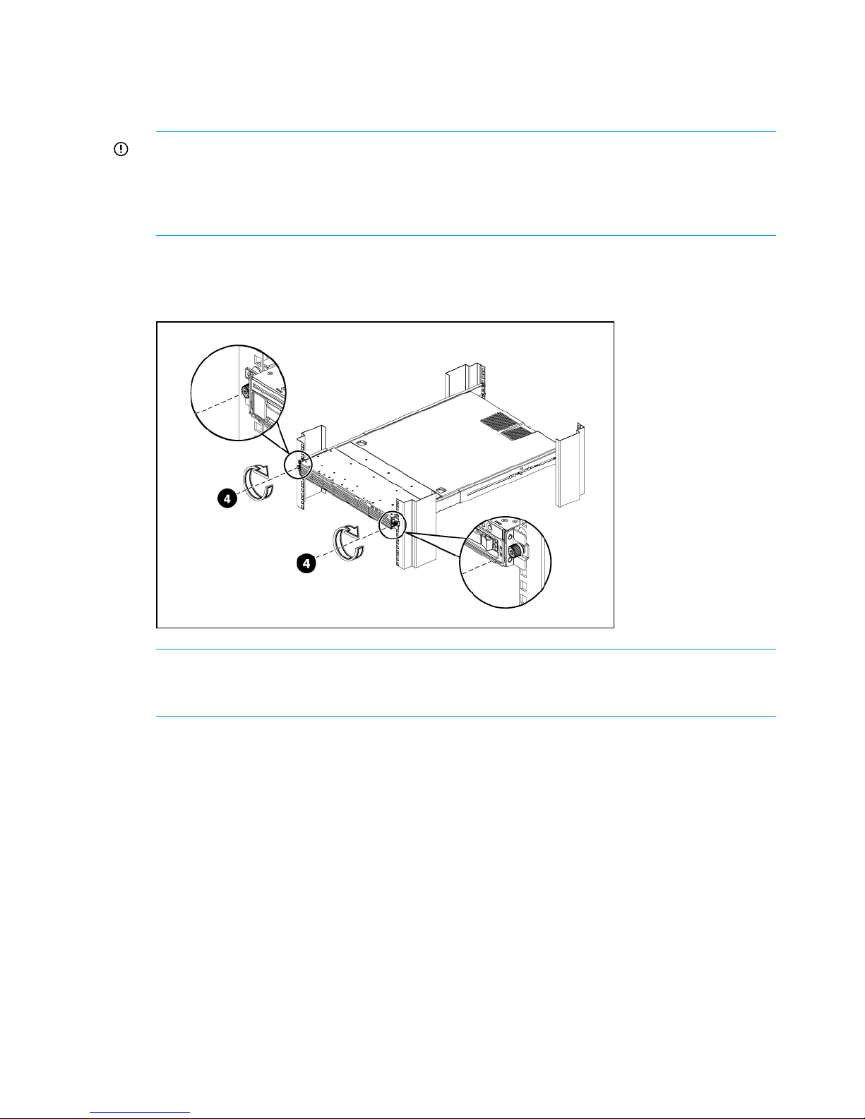
The following figure illustrates how to mount the HP StoreOnce Backup system, using the HP
StoreOnce 2700 model as an example.
Figure 1 Secure the HP StoreOnce Backup system to the rack
NOTE: The HP StoreOnce 2700 Backup system is supplied with a single power supply. If
you have purchased the optional second power supply, be sure to install it before continuing
with the installation.
Attaching SFPs, StoreOnce 2900, 4500 and 4700 only
The Accessory Kit supplied with the HP StoreOnce 4500 and 4700 Backup system contains the
appropriate number of 8Gb Short Wave FC SFP+ and 10Gb SR SFP+ transceivers.
The Accessory Kit supplied with the HP StoreOnce 2900 Backup system contains the appropriate
number of 10Gb SR SFP+ transceivers.
Unpack these and connect them to the corresponding ports on the rear of your product as shown
below.
12 Installing and cabling the HP StoreOnce Backup system
Page 13

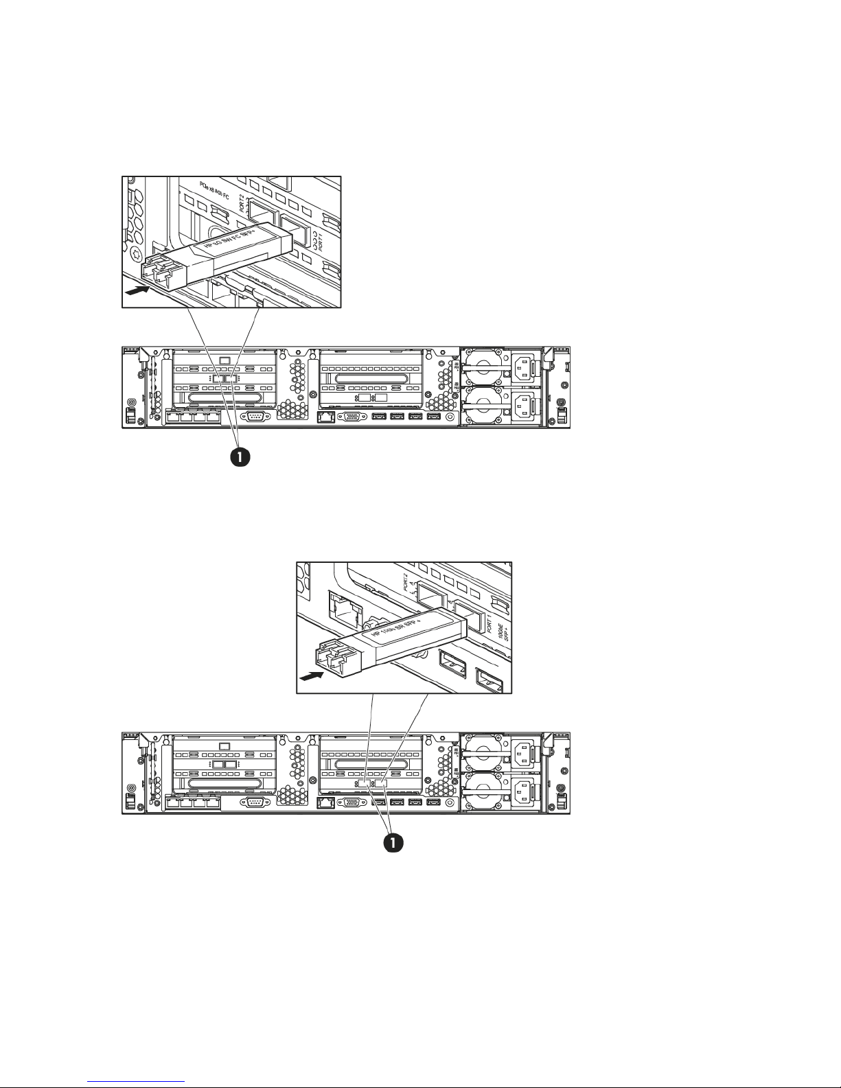
HP StoreOnce 4700 Backup
There are four FC ports and four 8Gb Short Wave FC SFP+s. Connect an SFP to each FC port, as
shown below (1).
Figure 2 Connecting FC SFPs on HP StoreOnce 4700
There are two 10 Gbit ethernet ports and two 10Gb SR SFP+s. Connect an SFP to each 10 Gbit
ethernet port, as shown below (1).
Figure 3 Connecting 10 Gbit ethernet SFPs on HP StoreOnce 4700
Attaching SFPs, StoreOnce 2900, 4500 and 4700 only 13
Page 14
HP StoreOnce 2900 and 4500 Backup
There are two FC ports and two 8Gb Short Wave FC SFP+s.
Connect an SFP to each FC port on the HP StoreOnce 4500 Backup, as shown below (1). (The
StoreOnce 2900 Backup does not have FC ports.)
Figure 4 Connecting FC SFPs on HP StoreOnce 4500
There are two 10 Gbit ethernet ports and two 10Gb SR SFP+s. Connect an SFP to each 10 Gbit
ethernet port, as shown below (1).
Figure 5 Connecting 10 Gbit ethernet SFPs on HP StoreOnce 2900 and 4500
14 Installing and cabling the HP StoreOnce Backup system
Page 15
Connecting the hardware
1. Use the supplied power cord(s) to connect the HP StoreOnce Backup system to the rack power
supply. This HP-approved cord is appropriate for your specific geographic region.
HP StoreOnce 2900, 4500 and 4700 Backup systems have a redundant power supply (this
also applies to the HP StoreOnce 2700, if a second power supply has been purchased and
installed). Make sure that both power cords are connected.
For detailed safety information, see the Safety Guide. Information about accessing this guide
can be found on the flyer included with your product.
2. HP StoreOnce 4700 Backup only: The storage enclosure supplied in the same pallet as the
head server unit must be connected to the HD SAS port on the RAID controller in slot 1, as
described in Connecting the first storage enclosure at installation (page 16).
3. For ease of installation connect LAN Port 1 on the head server unit to a 1 Gbit ethernet network
switch on a DHCP-enabled network. The appliance will use the default configuration and will
be available on the network after power up. You can then use the HP StoreOnce CLI commands
to further configure the network, as described in Network configuration, how to use StoreOnce
CLI commands (page 38).
NOTE: Use any CAT-5E or better network cable (also supplied with the product) to connect
to the 1 Gbit ethernet network switch. 100 Base-T Ethernet will limit performance.
If you are not using the quick install option, connect the required network port(s) and also
connect a console and keyboard to the video and USB connectors on the rear of the unit (see
drawings below for your product). You will need to configure the appliance manually after
power up so that it can be accessed on the network, see also Network configuration,
understanding the concepts (page 30)
4. If installing Capacity Upgrade enclosures at the same time, make sure they are cabled to the
HP StoreOnce Backup system and the rack power supply, as described in Connecting to the
Capacity Upgrade Kit (if required) (page 18).
5. Power up the HP StoreOnce Backup system. See Powering on and managing the StoreOnce
Management system (page 24).
NOTE: The HP StoreOnce Backup system also supports iLO4.
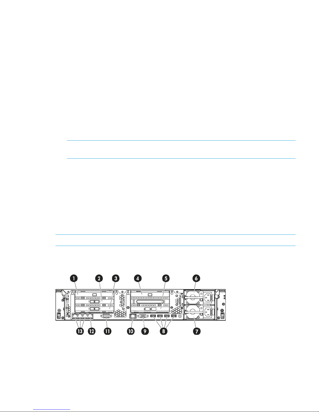
Connecting the HP StoreOnce 4700 Backup system
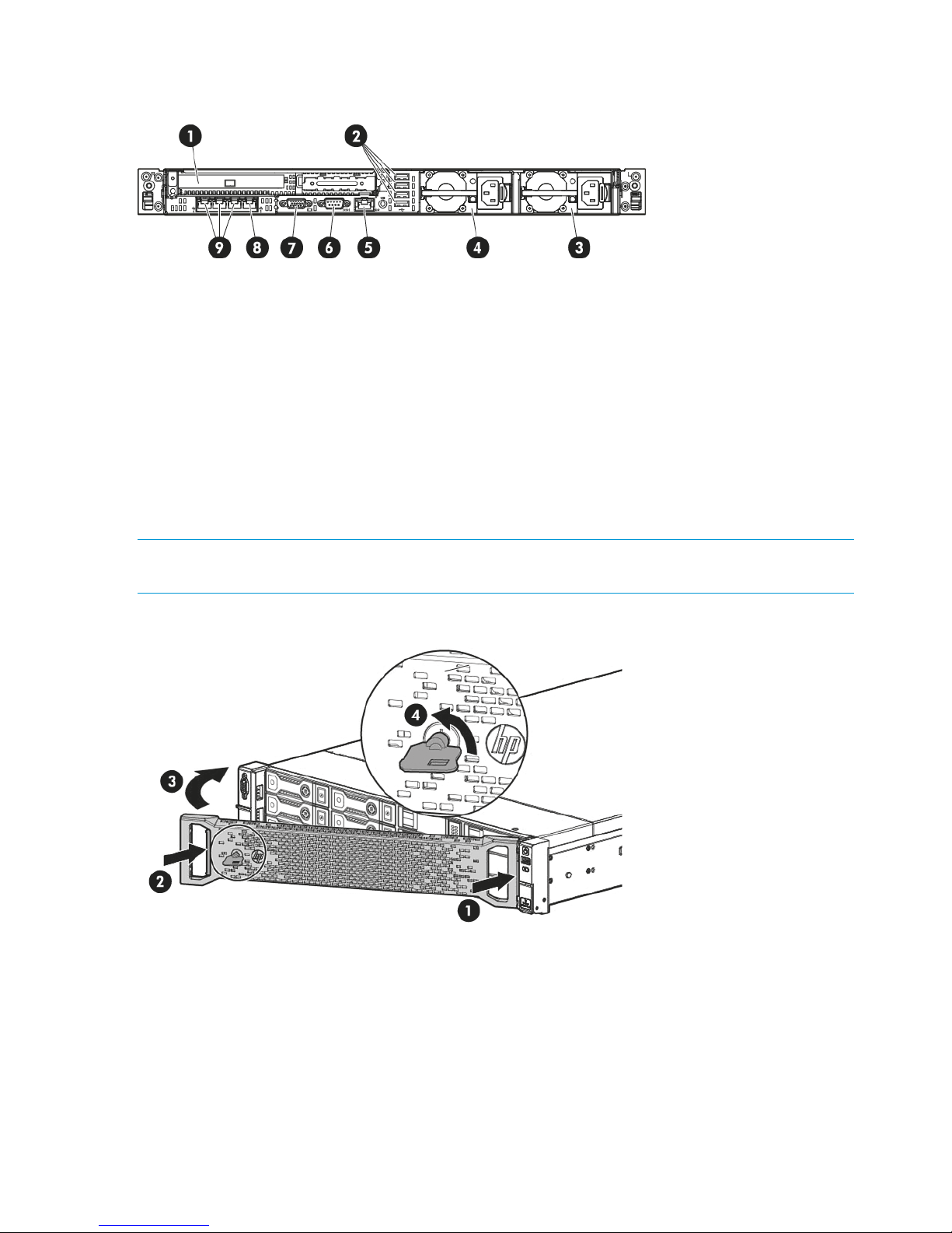
Figure 6 Rear view of the HP StoreOnce 4700 Backup system
FC card 12.RAID controller 11.
RAID controller 24.FC card 23.
Power supply bay 16.10 Gbit ethernet card5.
USB connectors (4)8.Power supply bay 27.
iLO4 port, do not use for data connection10.Video/monitor connector9.
Connecting the hardware 15
Page 16

1 Gbit ethernet network port 1, connect for
Quick Install
12.Serial connector11.
1 Gbit ethernet network ports 2, 3 and 413.
Connecting the first storage enclosure at installation
The HP StoreOnce 4700 Backup system consists of two units: a head server unit and a storage
enclosure in which the storage has already been configured.
IMPORTANT: The first enclosure is packaged along with the StoreOnce head server unit (in the
same pallet), its packaging and identification labels do not carry the part number BB881A. Any
4500/4700 24TB Capacity Kit expansions enclosures will be packed separately and will have
part number of an expansion kit (BB881A) on the outside and on the identification labels. It is very
important to connect the first enclosure to the correct RAID controller. Connecting the 4500/4700
24TB Capacity Kit to the enclosures incorrectly can result in incorrect behavior and may result in
failure to recognise the attached storage. Correction of this issue may result in the need for support
intervention.
Figure 7 Connecting the first storage enclosure to the HP StoreOnce 4700 Backup system
HD SAS port on RAID controller in slot 12.Head server unit1.
Power on button4.Expansion enclosure3.
Power connectors6.P1 port on expansion enclosure5.
1. Connect the square HD connector on the longer HD SAS cable to the single high-density SAS
port on the RAID controller in slot 1 on the rear of the HP StoreOnce Backup system. Ensure
that the cable connector is plugged in the correct way on the rear of the HP StoreOnce Backup
system. This connector is square and is not keyed. Insert the connector with the blue removed
tab at the top and push in until the connector clicks into place.
2. Connect the mini-SAS connector on the other end of the cable to the P1 connector on the rear
of the storage enclosure.
3. Use the supplied power cords to connect the storage enclosure to the mains power supply.
4. Power on the storage enclosure before the head server unit. You may need to hold down the
power on button for a few seconds.
16 Installing and cabling the HP StoreOnce Backup system
Page 17
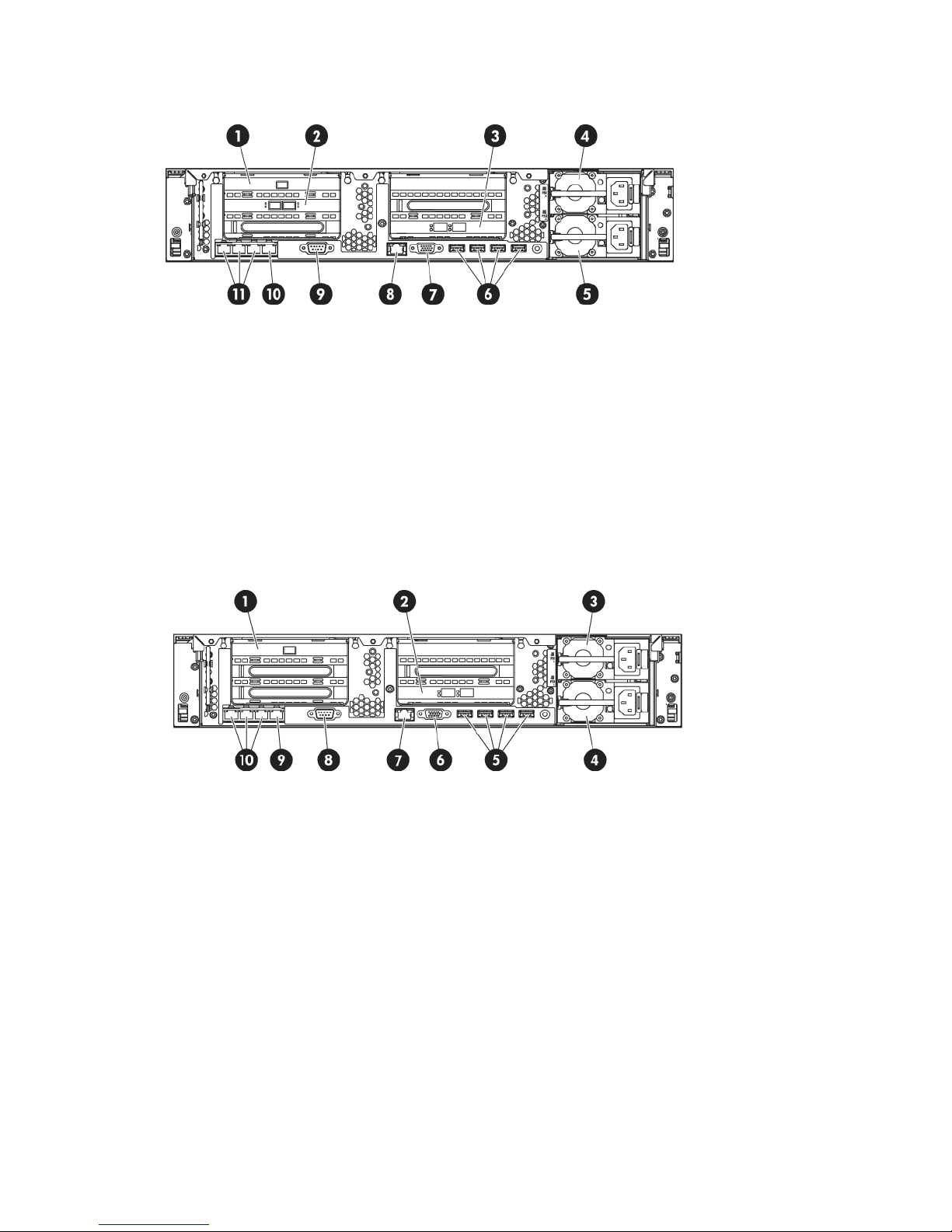
Connecting the HP StoreOnce 4500 Backup system
Figure 8 Rear view of the HP StoreOnce 4500 Backup system
FC card 12.RAID controller 11.
Power supply bay 14.10 Gbit ethernet card3.
USB connectors (4)6.Power supply bay 25.
iLO4 port, do not use for data connection8.Video/monitor connector7.
1 Gbit ethernet network port 1, connect for
Quick Install
10.Serial connector9.
1 Gbit ethernet network ports 2, 3 and 411.
Connecting the HP StoreOnce 2900 Backup system
Figure 9 Rear view of the HP StoreOnce 2900 Backup system
10 Gbit ethernet card2.RAID controller 11.
Power supply bay 24.Power supply bay 13.
Video/monitor connector6.USB connectors (4)5.
Serial connector8.iLO4 port, do not use for data connection7.
1 Gbit ethernet network ports 2, 3 and 410.1 Gbit ethernet network port 1, connect for
Quick Install
9.
Connecting the hardware 17
Page 18
Connecting the HP StoreOnce 2700 Backup system
Figure 10 Rear view of the HP StoreOnce 2700 Backup system
USB connectors (4)2.RAID Controller – external port is unused1.
Power supply bay 2 (optional)4.Power supply bay 13.
Serial connector6.iLO4 port, do not use for data connection5.
1 Gbit ethernet network port 1, connect for
Quick Install
8.Video/monitor connector7.
1 Gbit ethernet network ports 2, 3 and 49.
Attaching the security bezel
The product is supplied with a security bezel that is placed inside the box, and not delivered
pre-installed on the servers. Once the server is installed within the rack, the security bezel may be
clipped to the front of the unit. No special tools are required to do this.
NOTE: The key to lock the bezel is attached to the back of the security bezel. Only one key is
supplied.
Figure 11 Attaching the security bezel
Connecting to the expansion enclosure (HP StoreOnce 4500 and 4700)
Install the rail kit and expansion module(s) immediately below or above the HP StoreOnce Backup
system.
• HP StoreOnce 4700 Backup system: The first 24TB disk enclosure must be installed at the
same time as the head server unit and connected to the correct RAID card as described in
Connecting the first storage enclosure at installation (page 16). Up to seven 24TB expansion
enclosures, HP StoreOnce 4500/4700 24TB Capacity Kit (BB881A), may be installed at the
same time or added later. Expansion enclosures may be daisy chained. The user is advised
18 Installing and cabling the HP StoreOnce Backup system
Page 19

to make a record of which enclosure (serial number) is connected to which RAID card for
future reference.
• HP StoreOnce 4500 Backup system: Up to three expansion enclosures may be connected
and they are daisy chained. Two expansion options are available: HP StoreOnce 4500/4700
24TB Capacity Kit (BB881A) and HP StoreOnce 4500 48TB Capacity Kit (BB909A).
• HP StoreOnce 2700 Backup system: This model does not support connection of an expansion
enclosure.
• HP StoreOnce 2900 Backup system: This model supports capacity expansion, but the expansion
kit is a set of six 24TB hard disks that are installed in the head server unit. See Adding disks
for capacity expansion (2900 only) (page 22)
Installing expansion enclosures with the HP StoreOnce 4700
If you have purchased extra expansion enclosures, the storage in these additional enclosures will
not have been configured. For instructions on configuring additional expansion enclosures, see
Expanding storage (page 62).
Various cabling options are possible with the HP StoreOnce 4700 Backup system depending upon
available rack space, but the recommended configuration is to install the expansion enclosures
evenly above and below the head server unit.
The following table illustrates the recommended sequence in which enclosures should be attached
and distributed across the two RAID controller cards.
Table 2 HP 4700, the order in which shelves should be attached
Connect sequence for expansion shelves
to RAID card in Slot 4to RAID card in Slot 1Shelf
First1
Second2
Third3
Fourth4
Fifth5
Sixth6
Seventh7
Eighth8
Connecting to the expansion enclosure (HP StoreOnce 4500 and 4700) 19
Page 20
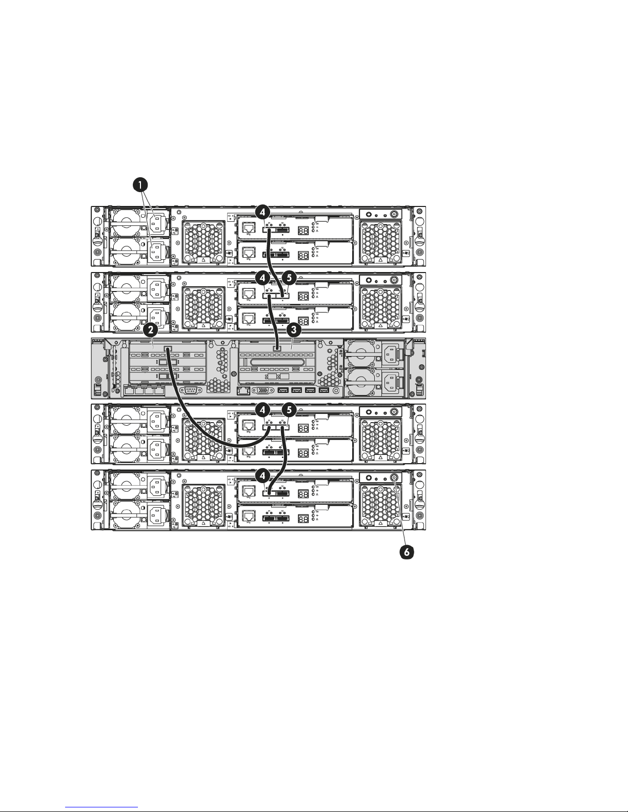
In the following example three further expansion shelves have been connected in addition to the
first shelf that is always required. When adding the second and subsequent shelves it is necessary
to expand storage.
The second expansion enclosure is connected to the RAID controller in slot 4, again using the
longer HD SAS cable. Subsequent expansion enclosures are daisy-chained using the half-meter
mini SAS cables; for example, expansion enclosure 3 to enclosure 1 and expansion enclosure 4
to enclosure 2. The connection is from P2 on the upper module of the previous enclosure to P1 on
the upper module of the next enclosure, as illustrated below.
Figure 12 Cabling example for the HP StoreOnce 4700 Backup system
HD SAS port on RAID controller 12.Power connectors1.
P1 port on expansion shelf (Note how
subsequent shelves may be daisy chained)
4.HD SAS port on RAID controller 23.
Power on button6.P2 port on expansion shelf (connects to P1 on
adjacent expansion enclosure)
5.
Installing expansion enclosures with the HP StoreOnce 4500
The HP StoreOnce 4500 Backup base system contains 12 disks. Up to three Capacity Upgrade
Kits may be connected if more storage is needed. Compatible cables are provided with the Capacity
Upgrade Kit; a longer HD SAS cable to connect the expansion shelf to the head unit and a half-meter
mini SAS cable for daisy-chaining subsequent shelves.
20 Installing and cabling the HP StoreOnce Backup system
Page 21

When installing an additional expansion enclosure with the HP StoreOnce 4500 Backup system,
the storage in that enclosure will not have been pre-configured and is not ready to use until storage
has been expanded. See Expanding storage (page 62).
Figure 13 Cabling example for the HP StoreOnce 4500 Backup system
P1 port on expansion enclosure (Note how
subsequent enclosures may be daisy chained)
2.head server unit1.
Power on button4.P2 port on expansion enclosure (connects to
P1 on adjacent expansion enclosure)
3.
Power connectors5.
1. Connect the square HD connector on the longer HD SAS cable to the single high-density SAS
port on the RAID controller on the rear of the HP StoreOnce Backup system. Ensure that the
cable connector is plugged in the correct way on the rear of the HP StoreOnce Backup system.
This connector is square and is not keyed. Insert the connector with the blue tab at the top
and push in until the connector clicks into place.
2. Connect the mini-SAS connector on the other end of the cable to the P1 connector on the rear
of the expansion enclosure.
3. If installing more than one expansion enclosure, use the supplied 0.5m mini SAS cables to
daisy chain up to three expansion enclosures in total. The connection is from P2 on the upper
module of the first enclosure to P1 on the upper module of the next enclosure, as illustrated
below.
4. Use the supplied power cords to connect the expansion enclosure to the main power supply.
Connecting to the expansion enclosure (HP StoreOnce 4500 and 4700) 21
Page 22
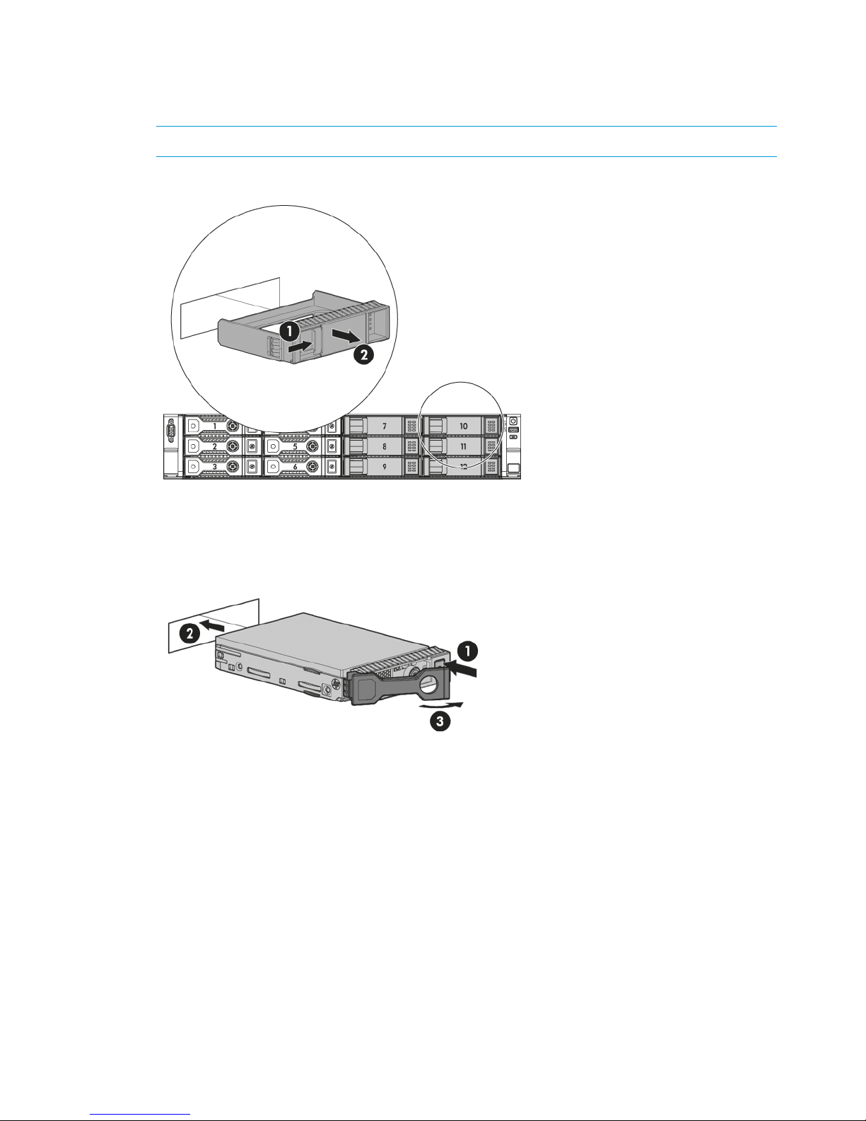
Adding disks for capacity expansion (StoreOnce 2900 only)
The Capacity Expansion kit contains six 4TB disks, which are installed in slots 7 to 12.
1. Remove the blanking plates from the disk bays.
NOTE: You must install all six disks at the same time.
Figure 14 Removing the blanking plates
2. Push the hard drive assembly into each drive bay (1) until it stops (2) and press the HDD
carrier latch (3) inward until it clicks.
Figure 15 Installing the hard disks
3. Attach the front bezel when all six disks are installed.
22 Installing and cabling the HP StoreOnce Backup system
Page 23

Figure 16 Attaching the front bezel
4. The license for the Capacity Expansion Kit must be applied and the storage expanded, using
StoreOnce CLI commands, before the extra capacity is available for use.
Adding disks for capacity expansion (StoreOnce 2900 only) 23
Page 24

3 Powering on and managing the StoreOnce Management
system
In this chapter:
• Powering on expansion shelves (page 24)
• Powering on the HP StoreOnce Backup system (page 24)
• Discovering the HP StoreOnce Backup system on the network (page 25)
• Accessing the StoreOnce Management console (page 25)
• User roles and accounts (page 26)
• Password best practices (page 27)
Powering on expansion shelves, HP 4500 and 4700 only
If expansion shelves have been connected, ensure that any expansion shelves attached to the
system are powered on (1) before pressing the Power button on the head server units. You may
need to hold down the power on button (on the rear of each unit) for a few seconds.
IMPORTANT: HP StoreOnce 4700 only: The first storage enclosure must always be connected to
the correct RAID card in the head server unit before power on. If it connected incorrectly, the
Hardware tree in the StoreOnce GUI will display errors.
Figure 17 Powering on expansion shelves
Powering on the HP StoreOnce Backup system
Press the Power on button (1) on the front of your HP StoreOnce Backup system. The normal boot
sequence takes approximately 5 minutes. On power up the HP StoreOnce Backup system runs its
fans at high speed for approximately 10 seconds before returning to normal speed.
Figure 18 Powering on the HP StoreOnce 4700 Backup system
24 Powering on and managing the StoreOnce Management system
Page 25

Figure 19 Powering on the HP StoreOnce 2900 and 4500 Backup system
Figure 20 Powering on the HP StoreOnce 2700 Backup system
1. Power On button
Discovering the HP StoreOnce Backup system on the network
If you have used the Quick Install option of connecting LAN Port 1 to a DHCP-enabled 1 Gbit
ethernet network, you can connect to and manage the StoreOnce Backup system from any client
attached to the same network using the appliance's Fully Qualified Domain Name (FQDN). The
FQDN is on a label/sticker on the server. Once connected, run the StoreOnce CLI network
commands to optimize your network configuration.
If your network is not DHCP enabled or you have attached to a different network port, connect a
monitor with keyboard directly to the appliance to configure initial network settings using the
StoreOnce CLI commands. As a minimum, you must configure network access to the StoreOnce
CLI and GUI across the internet. Once configured for internet access, use the StoreOnce CLI or
GUI, as appropriate, to manage the appliance and refine network settings, as appropriate.
NOTE: For ease of initial configuration HP recommends using the net set wizard StoreOnce
CLI command to configure the network. This wizard presents a series of questions, using the answers
you provide to configure the appliance on the network. See Network configuration, how to use
StoreOnce CLI commands (page 38) for more information and network configuration examples.
Accessing the StoreOnce Management Console
There are two ways of accessing the StoreOnce Management Console:
• Using the StoreOnce Command Line Interface, CLI
• Using the StoreOnce Web Management Interface, GUI
The StoreOnce CLI
The StoreOnce Command Line Interface (CLI) enables administration and monitoring of the system.
Many tasks, such as library and NAS share configuration and user management, and most network
configuration can be performed from either the StoreOnce GUI or the StoreOnce CLI; other tasks,
such as data in flight network configuration, SNMP configuration and date and time configuration,
can only be performed through the StoreOnce CLI. See the HP StoreOnce Backup system CLI
Reference Guide for more information about the StoreOnce CLI commands and their syntax.
Discovering the HP StoreOnce Backup system on the network 25
Page 26

1. StoreOnce CLI commands require an SSH client application (freely available from the internet)
and must be run from a SSH terminal session on a machine that is on the same network as
the StoreOnce appliance:
ssh <username>@<ip_address>
NOTE: StoreOnce CLI commands can also be run from a local console (Keyboard and
Monitor) attached to the appliance, for example, if the network is not yet configured.
2. At the prompts provide a User Name and Password (Admin, admin).
The StoreOnce GUI
The HP StoreOnce Management Console (GUI) is the main interface for:
• Monitoring the status and health of the HP StoreOnce Backup system and all configured backup
devices.
• Creating and modifying VTL and NAS StoreOnce backup targets and Catalyst stores (VTL and
NAS backup targets may also be created and managed using the StoreOnce CLI).
• Managing replication relationships and housekeeping.
• Setting up Remote Support.
To log on to the Management Console using the StoreOnce GUI, use any machine connected to
the same network as the appliance. The HP StoreOnce Backup system uses a secure network
connection.
1. Enter: https://<IP_address>
You may also use the Fully Qualified Domain Name (FQDN)
NOTE: If you use http: in the URL, you are automatically forwarded to the https: secure
network connection.
2. The StoreOnce Management Console displays the Login prompt. Provide a User Name and
Password (Admin, admin). You can also set the local language to display the text within
StoreOnce GUI from the Login screen.
IMPORTANT: The web browser used to communicate with the HP StoreOnce Backup system
requires Active Scripting or JavaScript enabled. Without these scripts enabled, some browser
buttons may not display.
User roles and accounts
Two roles define the permissions associated with a user; admin and user. Two default user accounts,
one for each role, are created automatically when the system is installed.
• Administrator: Authorized users can create and edit management and StoreOnce functions
via the GUI and CLI. The default login and password are Admin and admin. The permissions
role of the Administrator is admin.
• Operator: This account limits access to the GUI and CLI to monitoring and viewing. The default
login and password are Operator and operator. The permissions role of the Operator is user.
It is good practice to determine what other users will be required and what access to the system
they should have as part of the planning process. In particular, will the HP StoreOnce Backup
system be added to an Active Directory Domain?
The following AD domain details will be required to configure AD.
• The AD domain name and whether it is on an IPv4 or IPv6 network
• The user name and password of the Domain Administrator or a delegated user with Domain
Administrative rights
26 Powering on and managing the StoreOnce Management system
Page 27

Once the StoreOnce Backup system has been joined to an AD domain, you can configure external
users or external groups on the StoreOnce Backup system. The users or groups must already exist
on the AD domain. You can add AD domain users or groups with access to all StoreOnce features
or you can add them as Local Administrators for the CIFS server only. When you add AD domain
users through the CIFS server tab they are automatically created as Local Administrators, whether
or not they are admin users on the AD domain. This provides a way of implementing Delegated
Administration, which is not available for the StoreOnce device from the Active Directory
Management tool.
Only the name is required to configure AD users or groups on the StoreOnce Backup system;
passwords are configured on the AD domain server.
Password best practices
• Changing the passwords for the default user accounts (Administrator, Operator,
HPresetpassword and iLO) after installation is strongly recommended. Be sure to make a note
of the new passwords and save them to a secure location, such as an offline Password Security
tool.
NOTE: Note that once the Admin account password has been changed, its password cannot
be changed back to admin as this password is not sufficiently complex. The only way to revert
that password back to admin is via the HPresetpassword account which is only available on
the local console of the device.
• As you create new users, use the StoreOnce CLI system save config command to save
details of the new user accounts. This command does not save the password details, so
passwords for additional users should also be saved offline and kept in sync with the details
held on the HP StoreOnce Backup system.
User account and password requirements
• Local accounts can be between 1 & 16 characters in length and contain only alpha/numeric
and the following symbols - _
• External names may be up to 256 characters in length and contain alpha/numerics and the
following symbols: ~`!#$%()_-{}'.@\
• New passwords must be between 1 and to 24 characters and may contain only alpha\numerics
and the following symbols !@#$%^&* . The new password may not be the same as the current
password. The new password is not supplied for external users or groups.
Password best practices 27
Page 28

4 Configuration using the system set config wizard
The StoreOnce CLI command set provides two configuration wizards:
• The system set config command sequence packages a number of commands, some of
which you may skip, if required. This wizard is recommend if you wish to configure time and
license settings at the same time as network settings and run a health check. The network
configuration element of this wizard uses the net set wizard command.
• The net set wizard command sequence configures network settings and is described in
detail in Network configuration, how to use StoreOnce CLI commands (page 38).
Abstract
It is recommended that you read Network configuration, understanding the concepts (page 30)
before running either wizard for the first time.
System configuration using system set config command
The recommended configuration option at installation is to use the StoreOnce CLI wizard, system
set config. This command sequence packages a number of commands, some of which you
may skip, if required.
Before running the wizard collect and verify the required network information, see Before running
net set wizard (page 39).
Four actions are available at each step, as shown in the example below; execute, skip, back
and quit. (The network must be configured.)
# system set config
The following configuration steps will be performed.
—>Configure Network
Configure Time
Configure Licenses
Verify Hardware health
Finish Configuration and reboot
Finish Configuration
Actions:
execute) Perform current step (Default)
skip) Skip to the next step
back) Go back to a previous step
quit) Exit the configuration immediately
Each of the configuration steps listed above in the wizard is now described in more detail.
Configure network
This step runs through the network configuration and is equivalent to running the net set wizard
command. This step must be completed.
The wizard guides you through the network configuration on the StoreOnce Backup system. It
configures all network settings for all subnets.
NOTE: See Network configuration using net set wizard (page 41) for an example net set
wizard sequence.
Configure Time
This step allows you to set the time explicitly or set it using NTP server. If you select NTP server you
will be asked to specify up to two NTP server names (or IP addresses) and select the timezone.
You may skip this step and configure time later. See Setting up time and date (page 59).
28 Configuration using the system set config wizard
Page 29

Configure Licenses
The customer must provide license information if this step is to be executed.
You may skip this step and the customer may configure licenses later, if the required License To
Use (LTU), for example for replication, have not yet been obtained. See Configuring
licenses (page 60),
Verify Hardware health
This step generates a file called HealthReport<timestamp> in the health folder of the
StoreOnce folder structure, which you can copy after installation as a record of system health. This
file may be accessed over SFTP and contains status information on hardware, filesystem and service
set. For more information about accessing StoreOnce folders and the files in them, see Accessing
the StoreOnce Backup system over SFTP (page 63).
Finish Configuration (and reboot)
Choose either Finish Configuration and reboot or Finish Configuration. If you have reset the time
of the HP StoreOnce Backup system so that it has moved backwards, the configuration must be
completed with a reboot.
This performs a couple of tasks:
• Save the configuration details
Two configurations, devconfig<timestamp>.txt containing network and other device
management settings and devconfig<timestamp>.zip containing backup targets, email
settings, user accounts and so on are saved in the config folder. But at installation they
contain only the settings that have been configured during installation. It is strongly
recommended to use StoreOnce CLI commands to save the configuration again after backup
targets, email settings, user accounts and so on, have been configured, as described in Saving
configuration file (page 72).
• Collect a support ticket
This can take up to 20 minutes to complete because it is saving a record of the initial setup
and you will not be able to use the StoreOnce CLI during this period, although the StoreOnce
GUI will still be accessible.
If you choose the reboot option (recommended), the HP StoreOnce Backup system will then reboot.
System configuration using system set config command 29
Page 30

5 Network configuration, understanding the StoreOnce
networking concepts
If you are new to the StoreOnce networking environment, read this chapter. For examples of using
the StoreOnce CLI commands to configure the network go to Network configuration, how to use
StoreOnce CLI commands (page 38). For information on using the StoreOnce GUI to configure
the network go to Network configuration, how to use StoreOnce GUI (page 53).
In this chapter:
• Network configuration basics (page 30)
• Network configuration guidelines (page 35)
• Deciding whether to use the StoreOncer CLI or the StoreOnce GUI (page 36)
• Physical ports and IP addresses (page 36)
Network configuration basics
HP StoreOnce Backup systems support both IPv4 and IPv6 address protocols. IPv4 is available for
backup to all target devices, for replication and StoreOnce Catalyst Copy, and for appliance
management. IPv6 is supported for backup to StoreOnce Catalyst stores, replication and Catalyst
Copy, and for appliance management. It cannot be used for backup to VTL or NAS shares. All
systems also support DHCP (v4 and v6).
Network configuration components
The network is defined in a single network configuration with three main components: DNS server
settings, Port Set settings and Subnet settings. The key points to understand when creating or
modifying the configuration are described below.
DNS servers
Up to three DNS servers (one primary, and two backup servers if the primary is unavailable) may
be configured for the StoreOnce Backup system. These may have IPv4 and/or IPv6 addresses and
apply across all Port Sets and Subnets defined within the configuration.
In order to use FQDNs “Fully Qualified Domain Names” rather than an IP address to access the
StoreOnce system, the DNS server addresses that you provide should be able to resolve addresses
for all configured subnets. If you are using IPv4 and IPv6 addressing, then DNS servers configured
need to be able to resolve both IPV4 and IPV6 FQDNs.
NOTE: DNS Server and Gateway addresses will not be acquired in the following Subnet
configuration:
• VLAN Tag Enabled Subnet configured
• Addressing mode set to DHCP with the expectation of acquiring IPv6 address details
• DHCPv6 Server is running on a Windows Server operating system
In this configuration it is possible to manually provide the DNS Server and Gateway addresses
that should have been acquired via DHCPv6.
30 Network configuration, understanding the StoreOnce networking concepts
Page 31

Port sets
• A port set defines the physical 1 Gbit and 10 Gbit Ethernet ports that you intend to connect
to your network.
• A port set also defines the network bonding mode (1, 4 or 6) for the ports and whether they
are VLAN enabled. (VLAN tagging enables more subnets to be accessed without extra NIC
host bus adapters.)
• At least one Port Set must be configured to support connection to the StoreOnce Management
CLI and GUI. Further Port Sets may be defined, according to the number and type of physical
ports still available and how they are bonded.
• Each Port Set will have at least one Subnet.
• If the Port Set is not VLAN enabled, it may be configured with one Data Subnet that uses the
IPv4 protocol and one Data Subnet that uses the IPv6 protocol. (This configuration is sometimes
referred to as a dual stack configuration.)
• If the Port Set is VLAN enabled, multiple virtual subnets (IPv4 and IPv6), up to a maximum of
128 for the whole system, may be attached to a single Port Set. If VLAN enabled, a Port Set
cannot use bonding mode 6.
• StoreOnce software version 3.13.x and later allows you to define the amount of data contained
in an Ethernet frame, the default it 1500 bytes. Larger size frames, often referred to as "Jumbo"
frames, can improve performance of the Port Set; the maximum is 9000 bytes. Smaller frames
are also supported; the minimum is 1280 bytes.
IMPORTANT: Other devices on the network (clients and switches) must also be configured
to enable Jumbo frames for transfer of frames larger than 1500 bytes to be possible and to
avoid packets fragmenting or dropping.
Subnets
Subnets define the network paths used by clients to access the StoreOnce Backup system for Backup
and Management, and the network paths that are used for StoreOnce Catalyst Copy and
Replication.
• Subnets are attached to each Port Set that is configured. Both IPv4 and IPv6 address protocols
are supported. Single-node systems also support DHCP. See Network configuration subnet
fields (page 56) for more details.
• IPv6 is supported for backup to all StoreOnce Catalyst stores, replication and Catalyst Copy,
and for appliance management. It cannot be used for backup to VTL or NAS shares (CIFS or
NFS).
• If multiple Subnets are defined, one (and only one) Subnet for each protocol, IPv4 and IPv6,
must always be designated as the default Subnet for routing traffic to IP addresses that are
not within the configured Subnets.
• StoreOnce software version 3.11.0 and later provides support for Data In Flight Encryption
using the IPsec protocol. This can only be configured using the StoreOnce CLI. For instructions
on configuring encryption on the StoreOnce Backup system, see the HP StoreOnce CLI
Reference Guide.
The following diagram provides a simplified overview of the hierarchy within a network configuration
for a StoreOnce Backup system.
Network configuration basics 31
Page 32

Figure 21 Network configuration hierarchy
Port numbering for hardware products
The StoreOnce CLI and the HP StoreOnce Management GUI label port numbers differently. The
following table equates the port numbering as it is referred to in the StoreOnce CLI with the port
naming on the HP StoreOnce Management GUI.
Table 3 Port numbering
StoreOnce Models
1 Gbit or 10 Gbit
ethernet
HP StoreOnce
Management GUI
StoreOnce CLI
and GUI
All models1 GbitPort 1eth0
All models1 GbitPort 2eth1
All models1 GbitPort 3eth2
All models1 GbitPort 4eth3
4900, 2900, 4700 and 4500, but not 270010 GbitPort 1eth4
4900, 2900, 4700 and 4500, but not 270010 GbitPort 2eth5
4900 only, not 2700, 2900, 4500 or 470010 GbitPort 3eth6
4900 only, not 2700, 2900, 4500 or 470010 GbitPort 4eth7
NOTE: On the HP StoreOnce Management GUI you can display a picture of where the ports
are by editing a portset and clicking the Show Port Picture link.
32 Network configuration, understanding the StoreOnce networking concepts
Page 33

Network bonding modes
Each set of network ports on the appliance can be configured either on separate Subnets or in a
bond with each other (1 Gbit and 10 Gbit ethernet ports cannot be bonded together).
Three bonding modes are supported:
• Mode 1 (Active/Backup)
This is the most simple bonding mode; it allows network traffic via one active port only and
requires no specific extra switch configuration. It is recommended for simple network
connections, if the active network link fails then traffic moves to the backup port.
• Mode 4 (IEEE 802.3ad Dynamic Link Aggregation)
This bonding mode is also known as LACP and requires a special external switch configuration.
It provides a link aggregation solution, increasing the bond physical bandwidth, but only
works if all the ports in the bond are connected to one switch or switches joined by an
interswitch link. It is recommended when:
◦ The customer wants to increase throughput to the StoreOnce appliance.
◦ Trunks between switches on the customer network already use LACP mode.
The LACP protocol only works when it is configured on both the network switch and StoreOnce
end of the connection. Please refer to your switch documentation for information on LACP
configuration.
• Mode 6 (Active Load Balancing)
This mode provides a load balance solution. It does not require specific external switch
configuration but does require the switch to allow ARP negotiation. It can be used in a 2–switch
configuration.
This configuration is generally recommended for backup data performance and also for
resiliency of both data and management network connectivity. However, in some environments
ARP packet negotiation may be disabled within the network infrastructure, so this mode may
not be appropriate.
NOTE: When using bonded ports the full performance of bonded links are only realized if multiple
host servers are providing data, otherwise data will still use only one network path from the single
server.
VLAN Subnets with HP StoreOnce Backup
There is a fixed number of available physical NIC ports on the HP StoreOnce Backup, defined by
the number of 1 Gbit ports plus 10 Gbit ethernet ports, therefore there is a limit on the number of
physical Subnets to which the HP StoreOnce Backup can be directly connected. If your network
requires more Subnets than this—for example, twenty—the network administrator can define 20
VLANs, each with its own Subnet and, typically, use the 10 Gbit ethernet bonded link to the HP
StoreOnce Backup as a trunk.
To do this, the network administrator sets up the switches with the necessary VLANs and identifies
20 tags. (The tag values can be any integer between range 2-4094.) The ports on the network
switch to which the StoreOnce Backup connects must be trunked and tagged. Then using the
StoreOnce CLI, the HP StoreOnce administrator modifies the network configuration by first defining
the Port Set for the physical 10 Gbit ethernet link and making it VLAN enabled, and then configuring
each of the twenty VLAN Subnets to use that Port Set.
Network configuration basics 33
Page 34

VLAN guidelines
The following guidelines apply:
• The user can configure up to a total of 128 different VLAN Subnets on each StoreOnce Backup;
the VLAN Subnets may be consecutive or non-consecutive.
• The user can configure all VLAN Subnets on one Port Set or divide the VLAN Subnets over
multiple Port Sets.
• It is not permitted to configure VLAN Subnets on a Port Set that uses Mode 6 network bonding.
• Each VLAN tag interface is configured using the VLAN ID index, which is the same as the
switch VLAN ID number and must be an integer from 2 to 4094.
• Each VLAN tag interface can configured for use with one IPv4 and one IPv6 subnet.
For example, if a VLAN tag ID was configured for use with ports eth 0 and eth1 on IPv4, it
can also be configured for use on IPv6 with that Port Set but it cannot be used with any other
Port Set.
• The user can add/delete/modify the VLAN network configuration without interrupting
non-affected network configuration on the appliance.
• VLAN tagging does not increase bandwidth because the bandwidth is bound by the physical
speed of the Port Set. The number of open streams is bound by the specification for the
StoreOnce appliance.
• StoreOnce monitoring is on the physical Port Set, not on each VLAN Subnet.
• VLAN tagging is not a multi-tenancy solution. Once configured, all StoreOnce services can
bind / listen to all VLAN Subnets. For example the NAS shares are available on all configured
Subnets, and permissions are required to regulate access to shares.
Example network environment
In the following example the following Port Sets are configured on the StoreOnce Backup:
• eth0 is the Quick Install connection that was created by connecting LAN port 1 at installation.
It uses DHCP and is not VLAN enabled. If required, it can be reconfigured with static IP
addresses.
• eth2 and eth3 are used for the StoreOnce Catalyst Copy and Replication Subnet and provide
the default gateway to the WAN. This Port Set is also not VLAN enabled and is configured
to support one IPv4 Subnet. It uses the 1 Gbit ethernet ports, Port 3 and Port 4. If required,
one IPv6 subnet could be configured on this Port Set after installation.
• eth4 and eth5 are used for Backup Subnets. This Port Set is VLAN enabled and currently
supports two VLAN Subnets — one IPv4 subnet and one IPv6 subnet. Further IPv4 and IPv6
VLAN Subnets may be configured on this Port Set, as required, up to a maximum of 128. The
Port Set uses the 10 Gbit ethernet ports, Port 1 and Port 2.
• eth1, (the 1 Gbit ethernet port, Port 2), is available to support a further Port Set. (Some HP
StoreOnce Backups systems provide four 10 Gbit ethernet ports, and eth6 and eth7, (the 10
Gbit ethernet ports, Port 3 and Port 4) may also be configured to support further Port Sets.
However, these ports are not available on all models.)
NOTE: The availability and number of 10 Gbit ethernet ports depends upon the model of
StoreOnce Backup.
34 Network configuration, understanding the StoreOnce networking concepts
Page 35

Figure 22 Network example
Network configuration guidelines
For installations where you are not installing on a DHCP network it is necessary to use the StoreOnce
CLI wizard command sequence, net set wizard, to set up the basic network configuration
that gives you access to the StoreOnce GUI. The StoreOnce GUI or StoreOnce CLI may then be
used to refine the network configuration.
For more complex configurations, a major benefit of using the StoreOnce GUI is that the
configuration can be saved at any point in the network configuration process. See the appropriate
HP StoreOnce Installation and Configuration guide for your product for examples of using the
StoreOnce CLI to configure the network.
NOTE: If you are installing on a DHCP network and you connect to LAN port 1, you do not need
to use the StoreOnce CLI wizard command sequence. A basic network configuration is created
automatically for you, which gives you immediate access to the StoreOnce GUI. You can then use
the StoreOnce GUI pages to refine the network configuration.
When working with network configurations the following guidelines apply:
• There may be up to 16 configurations on any StoreOnce Backup system, but only one can
be active.
• There are two fixed configurations reserved for the system that cannot be modified:
Factory_Default_Configuration and current.
• Configuration names are alpha numeric.
• There are three stages to applying a new network configuration: create the configuration,
validate the configuration and activate the configuration.
Network configuration guidelines 35
Page 36

• Once a configuration is activated, it becomes the current configuration. There can be only
one current configuration.
• When activating a network configuration that contains many VLAN subnets, the process can
take many minutes. During this time the GUI will continue to show the previous configuration
until the new one is successfully applied. During activation, you can run the CLI command
network activate status to monitor the activation progress.
• Once you have finished creating a network configuration and whenever you modify a network
configuration, be sure to use the StoreOnce CLI to create a system configuration save and
restore file, using the StoreOnce CLI command, config save devices.
• Refer to the HP StoreOnce CLI Reference Guide for the full range of network and config save
and restore commands.
Deciding whether to use the StoreOnce CLI or the StoreOnce GUI
Most network configuration tasks may be carried out from the StoreOnce GUI, as described in
Network configuration, how to use StoreOnce CLI commands (page 38), or the StoreOnce CLI,
as described in Network configuration, how to use StoreOnce GUI (page 53). Configuring Data
in Flight encryption using IPSec is only possible via the StoreOnce CLI.
At installation
HP StoreOnce , 4700, 4500, 2900 and 2700 Backup systems support DHCP and the simplest
configuration at installation is to connect to LAN port 1 and log on to the StoreOnce GUI using
the name of the StoreOnce Backup system. If this address option is not supported on your DHCP
network or you have not connected to LAN port 1, you will need to connect to the local console
and query the DHCP-assigned address using the StoreOnce CLI command, net show status
all.
On HP StoreOnce , 4700, 4500, 2900 and 2700 Backup systems that are not in a DHCP
environment, the recommended option is to use the StoreOnce CLI command, net set wizard,
for basic configuration, and the StoreOnce GUI to set up more complex configuration settings.
After installation
Use the HP StoreOnce Management GUI, as described in the HP StoreOnce Backup system User
Guide, or the StoreOnce CLI, as described in the HP StoreOnce CLI Reference Guide, to copy a
configuration and make changes to it before validating and activating the configuration. A major
benefit of using the StoreOnce GUI, particularly if configuring multiple VLANs, is that you can save
the configuration as you work on it.
The Network Configuration tools are under HP StoreOnce — Device Configuration. Expand Network
Configuration in the navigation pane.
Physical ports and IP addresses
Before using the wizard or the GUI to configure the network, you should determine which subnets
you wish to configure and how they will use available ports on the StoreOnce Backup system.
1. Define how many subnets you wish to support for backup to the StoreOnce Backup system,
the speed at which you wish data to be transferred and whether you require ports to be
bonded.
2. This will determine how many physical port connections you require and whether the subnet
should be configured to use 1 Gbit or 10 Gbit ethernet ports.
NOTE: Remember that each port set (physical port connections) can support one IPv4 and
one IPv6 subnet.
36 Network configuration, understanding the StoreOnce networking concepts
Page 37

3. If you have more subnets than physical ports available on the StoreOnce Backup system and
your network environment supports VLAN subnets, consider using VLAN subnets to transfer
backup data to the StoreOnce Backup system. The StoreOnce Backup system must be connected
to a port on the network switch that is trunked and tagged.
4. If you wish to increase the frame size for a subnet, whole values between 1500 and 9000
kbytes are supported. Be aware that all components on the network, switches, etcetera, must
also support the larger frame size.
The following table shows network connections and IP address requirements for different port
combinations (port sets).
Table 4 Physical network port connection options and IP address requirements
IP addresses requiredNetwork configuration notesWhen to usePort set contains
Single network connection,
therefore one IP address only
Connect to a 1 Gbit or a 10
Gbit ethernet port and use
If the network interface is
required solely for
Single port only
per subnet configured for theindividual 1 Gbit and 10management of the
port set. (May be configuredGbit ethernet ports to createappliance or if low
for IPv4 and IPv6 subnet, or
for VLAN subnets.)
port sets, as best meets
requirements.
NOTE: If DHCP enabled
on network and connected
to 1 Gbit ethernet LAN port
1, StoreOnce Backup will be
discovered automatically on
network.
performance and resiliency
backup and restore are
acceptable.
Or, if servers to be backed
up are split across multiple
physical networks with
independent access to the
appliance.
Depends upon number of
networks and bonding
required
Two or more network ports
are configured within the
same port set and presented
Recommended for backup
data performance and also
for resiliency of both data
Multiple ports with bonding
When using bonded ports
the full performance of
1 Gbit ethernet
on a single IP Address for
subnet configuration.
and management network
connectivity.
bonded links will only be
realized if multiple host
servers are providing data.
2, 3 or 4 ports bonded = 1
IP address per subnet
Can make physical
connections to up to four 1
Gbit ethernet ports.
Mode 1 = One active port
on each bonded set, good
for resiliency
No bonding between 1 Gbit
ethernet and 10 Gbit
ethernet ports is allowed.
2 ports bonded leaves 2
ports free for use either in
one more port set, if
Can make physical
connections to both 10 Gbit
Mode 4 = Increased
throughput, but requires
switch configuration (LACP)
bonded, or in two more port
sets if not bonded
ethernet ports (not supported
on HP 2700).
Mode 6 = Good for
throughput and availability,
no switch configuration
10 Gbit ethernet
2 ports bonded = 1 IP
address per subnet
Physical ports and IP addresses 37
Page 38

6 Network configuration, how to use StoreOnce CLI
commands
If you are new to the StoreOnce networking environment, read the previous chapter before
attempting to configure the network.
This chapter describes how to use the StoreOnce CLI command, net set wizard, to configure
the network for the first time. If your network supports DHCP and you have connected to the network
over LAN port 1, you may also use the StoreOnce GUI to configure the network. Another option
is to use the StoreOnce CLI to configure a simple network connection and then use the StoreOnce
GUI to refine it. See the next chapter for more information about using the StoreOnce GUI to
configure the network.
In this chapter:
• Identifying available ports on the StoreOnce CLI (page 38)
• Before running net set wizard (page 39)
• Network configuration using net set wizard (page 41)
• Modifying a network configuration (page 48)
NOTE: For further examples of configuring the network using both the wizard and individual
StoreOnce CLI commands see also More networking examples (page 114).
Identifying available ports on the StoreOnce CLI
Identifying network ports available
All systems have four 1 Gbit ethernet ports that are identified as eth0 (LAN port 1) and eth1, eth2
and eth3 (LAN ports 2, 3 and 4).
HP StoreOnce 2900, 4500 and 4700 Backup systems have an additional two 10 Gbit ethernet
ports that are identified as eth4 and eth5.
NOTE: If you do not know what ports are available on your system, use the Show Ports link on
the Networking pages of the StoreOnce GUI to provide an illustration of the location of the physical
ports for your model.
You can also use the following StoreOnce CLI command:
# net show ports
This command will display the port layout of the StoreOnce Backup system with details of the ports.
# net show ports
=============================== Node X ==============================
| || |
| || | Port 2 | Port 1 | 10 GbE |
| || | | | |
|============ card 1 ============= ============ card 2 ============ |
| || |
| || |
| |
||Link4|Link3|Link2|Link1| | Ilo | |
======================================================================
Port Number OS Hardware Bonds 1G/10G
P1 eth0 - 1 Gig
P2 eth1 - 1 Gig
38 Network configuration, how to use StoreOnce CLI commands
Page 39

P3 eth2 - 1 Gig
P4 eth3 - 1 Gig
P5 eth4 - 10 Gig
P6 eth5 - 10 Gig
Bonding Modes Supported
1: Active Passive Bonding
4: Link Aggregate Control Protocol (LACP) Bonding
6: Active Load Balance Bonding
Command Successful
NOTE: The physical layout of 1 Gbit ethernet is reflected in the |link n| positioning of the
output. Looking at the rear of the HP StoreOnce appliance:
• eth3 = LAN port 4 (P4), eth2 = LAN port 3 (P3), eth1 = LAN port 2 (P2), eth0 = LAN port 1
(P1)
• eth4 (right) = P5 and eth5 (left) = P6 = 10 Gbit ethernet port on top card
Network bonding combinations
For single port connections, the Port Set contains just one port. However, for bonded connections,
a Port Set is a configuration of ports and bonding mode.
If you select a bonded configuration for your network, the StoreOnce CLI network wizard provides
a number of permutations for a Port Set, depending upon the availability and number of 1 Gbit
and 10 Gbit ethernet ports.
The example below is for an HP StoreOnce 2900, 4500 or 4700 Backup system, which has two
10 Gbit ethernet ports, and only one 10 Gbit ethernet bonding option.
Select bond configuration :
1 = eth0, eth1 (1 Gig) (default)
2 = eth0, eth2 (1 Gig)
3 = eth1, eth2 (1 Gig)
4 = eth0, eth1, eth2 (1 Gig)
5 = eth0, eth3 (1 Gig)
6 = eth1, eth3 (1 Gig)
7 = eth0, eth1, eth3 (1 Gig)
8 = eth2, eth3 (1 Gig)
9 = eth0, eth2, eth3 (1 Gig)
10 = eth1, eth2, eth3 (1 Gig)
11 = eth0, eth1, eth2, eth3 (1 Gig)
12 = eth4, eth5 (10 Gig)
IMPORTANT: Once you have created a Port Set, the ports that you have defined for that Port Set
are no longer available for use in other Port Sets.
Each port set may contain one physical IPv4 subnet and one physical IPv6 subnet. However,
multiple virtual subnets (VLANs) may be attached to a single Port Set (up to a maximum of 128).
See VLAN guidelines (page 34).
Before running net set wizard
NOTE: There is an alternative configuration wizard system set config that carries out a
number of additional configuration tasks, such as setting time, as well as running net set
wizard. Refer to Network configuration using system set config (page 28) or the StoreOnce
Backup system CLI Reference Guide for more information.
Before running net set wizard you must make a number of decisions about your network
configuration.
Before running net set wizard 39
Page 40

1. Do you wish to configure DNS servers? Up to three may be configured servers (one primary,
and two backup servers if the primary is unavailable) . Make sure you have the address details
before you start. These may be IPv4, IPv6 or a combination of both.
2. Are you connecting a single port or are you connecting multiple ports to your network?
3. Which Ethernet port(s) are you connecting (these are referred to as the port set)? If connecting
multiple ports, which network bonding mode should be used, the default is Active/Passive
bonding?
NOTE: You cannot bond a 1 Gbit with a 10 Gbit ethernet port.
4. If the ports are not VLAN enabled, you may configure the port set with one IPv4 and one IPv6
subnet.
5. If the ports are VLAN enabled, you may configure up to 128 VLAN subnets across the whole
system. Make sure that all details are available to configure the VLAN subnets and tag IDs.
IMPORTANT: If you are configuring multiple VLAN subnets, HP recommends configuring
only a couple initially in the wizard, After initial configuration, you can create a copy of the
configuration and edit the copy to attach the remaining VLAN subnets to Port Sets using
StoreOnce CLI commands, as illustrated in Modifying a network configuration (page 48). This
is because you will not be able to save the configuration as you build it and if you make a
keying error during the wizard, you may have to start again from the beginning.
TIP: Even if you intend to use solely VLANs to connect to your system, HP recommends
configuring one physical subnet to test the initial installation. The easiest way to do this is to
use the default Quick Install connection to LAN port 1 over DHCP. When assigning DHCP
settings, most of the network values can be taken from DHCP. However, you must provide
VLAN tag IDs, if VLAN subnets are required.
6. Which network protocol will each subnet use, IPv4 or IPv6?
7. Does your network use DHCP or static IP addresses?
If DHCP is used, it is recommended that once an IP address has been assigned, the system
Administrator should permanently associate that IP address with the StoreOnce Backup system.
This will avoid any problems with the IP address of the device changing over reboots.
If you select static IP addressing, make sure you know:
• IP address of the HP StoreOnce Backup system
• Subnet mask (IPv4) or Prefix (IPv6)
• Gateway IP address
• Default subnet
• Domain name, such as mycompany.com
8. The preceding information is sufficient to configure the network and once entered, the wizard
will display and ask you to confirm the specified settings. At this point, do you wish to configure
another subnet? For example, you may wish to dedicate one network to StoreOnce Catalyst
Copy and replication. Or, with HP StoreOnce 4700, 4500 and 2900 Backup systems, you
may wish to use the 10 Gbit ethernet network for backup data.
You will be prompted to provide details of the new subnet, as above.
9. When you have completed details for all subnets, you are asked to select which subnet will
provide the default gateway. The wizard then validates and activates the configuration and
it becomes the current configuration.
NOTE: Some features cannot be configured using the net set wizard. These include Data In Flight
Encryption and editing the default value, 1500 bytes, of the Ethernet Framesize for a Port Set.
40 Network configuration, how to use StoreOnce CLI commands
Page 41

Network configuration using net set wizard
NOTE: See Example network environment (page 34) for a diagram illustrating the network
configuration that we are creating in this example.
The net set wizard guides you through the network configuration on the StoreOnce Backup
system and configures all network settings for all subnets.
Before running the wizard collect and verify the required information, see Before running net set
wizard (page 39).
To make additions or modifications to an existing network configuration, do not use net set
wizard because this will overwrite the current configuration. Instead, use the net modify or
net add CLI commands, as described in Modifying a network configuration (page 48) and the
HP StoreOnce Backup system CLI Reference guide.
NOTE: If you wish to configure encryption on a subnet, you can only do this using the StoreOnce
CLI commands. It is not configurable using the wizard. See To add Data in Flight
Encryption (page 49).
In the following example we shall use the net set wizard to support the following network
configuration:
• Two DNS servers
• One Port Set that uses the eth0 port only and will be used for a DHCP subnet.
• A second Port Set that is used for the Backup Data subnets and uses the bonded pair of 10
Gbit ethernet ports, eth4 and eth5. This Port Set is VLAN-enabled. We shall set up one IPv4
VLAN subnet and one IPv6 VLAN subnet initially using the wizard, and then illustrate how to
modify the configuration to add a third VLAN subnet.
• A third Port Set that is used for StoreOnce Catalyst Copy and Replication subnet across the
WAN and uses the bonded pair of 1 Gbit ethernet ports, eth2 and eth3. We wish to use
Mode 6 bonding on this Port Set, so it cannot be VLAN enabled. This subnet will also be
configured with the default gateway.
NOTE: The wizard runs continuously. You cannot interrupt it and save the configurations already
specified. However, for the purposes of this example, we have split it into sections to add notes.
1. First, we shall specify the DNS servers and create Portset1 on eth0. We shall keep this as
DHCP in line with the Quick Install option. In reality, you are more likely to re-configure this
Port Set with static IP addresses, but we shall illustrate this as a post-installation example. See
Modifying a network configuration (page 48) for more information.
# net set wizard
StoreOnce Network Configuration Wizard
--------------------------------------
This Wizard will guide you through the configuration of
network settings on your StoreOnce Backup System.
If you wish to make additions or modifications to an existing
network configuration without having to reconfigure all settings,
use the 'net modify' or 'net add' commands instead.
See the User Guide guide for physical port layout details.
The wizard consists of the following steps:
Step 1) Set system wide DNS server addresses (optional) and cluster size (if multi-node)
Step 2) Configure network settings for available network adapters
Step 3) Save and apply all network settings
Type 'quit' + ENTER at any time to exit wizard.
Step 1) Set system wide DNS server addresses (optional) and cluster size (if multi-node)
----------------------------------------------------------------------------------------
Enter a list (max 3) of DNS servers separated by commas; this list may be blank.
The IP version used here must match that used on the management interface later on.
For example, for IPv4: 192.168.1.100,192.168.3.100
Network configuration using net set wizard 41
Page 42

For example, for IPv6: 2001:DB8::0,2001:DB8::1
-->172.1.1.100,172.1.2.100,2001:DB8::1
<--DNS servers: 172.1.1.100,172.1.2.100,2001:DB8::1
*Step Complete* Do you want to :
1 = Go to next step: Step 2) (default)
2 = Go back to start of present step: Step 1)
3 = Quit wizard and lose all settings
-->1
<--Navigation: Go to next step: Step 2)
Step 2) Configure network settings for available network adapters
-----------------------------------------------------------------
Select the type of configuration for this subnet
(Selecting "bonded" here will create a "Port Set" consisting of two separate NICs bonded together) :
1 = Single port (default)
2 = Bonded ports (note ports must be the same speed to bond)
-->1
<--Bonded/Single: Single port
Select network adapter :
1 = eth0 (1 Gig) (default)
2 = eth1 (1 Gig)
3 = eth2 (1 Gig)
4 = eth3 (1 Gig)
5 = eth4 (10 Gig)
6 = eth5 (10 Gig)
-->1
<--Single Port: eth0 (1 Gig)
Is this subnet on a Virtual LAN?
1 = No (default)
2 = Yes
-->1
<--VLAN/Not VLAN: No
Select Static or DHCP addressing :
1 = DHCP (default)
2 = Static
-->1
<--DHCP/Static: DHCP
Do you want to configure a static default gateway for this subnet or get the gateway information from
DHCP?
-------------------------------------------------------Note for ipv6 DHCP servers a static gateway is required.
--------------------------------------------------------
1 = Gateway obtained from DHCP server (default)
2 = Set gateway manually (this may be blank if no gateway is required)
-->1
<--Gateway: Gateway obtained from DHCP server
Do you want to configure the network domain name or get the domain name from DHCP?
1 = Domain name obtained from DHCP server (default)
2 = Set domain name manually (e.g. mydomain.local - this may be blank if no domain name is required)
-->1
<--Domain Name: Domain name obtained from DHCP server
---------------------Network: subnet_1
---------------------IP Addresses: dhcp
Netmask/Prefix: dhcp
Domain Name: dhcp
Gateway: dhcp
VLAN tag:
Port Set: Port Set_1 with these interfaces: eth0, Framesize: 1500
Encryption Links:
Bonding Mode: Not applicable
Is this configuration correct?
1 = Yes (default)
2 = No
-->1
42 Network configuration, how to use StoreOnce CLI commands
Page 43

<--Configuration okay: Yes
2. At this point, you have configured the network sufficiently to enable access to the StoreOnce
Management CLI and GUI. If preferred, you could complete the network wizard and carry
out the rest of the network configuration using the StoreOnce CLI commands. The wizard
would complete as described in step 4. (Note, these steps are artificial to enable a description
of what is happening. The wizard runs continuously.) For the purposes of our example, we
shall continue to create a second Port Set on the pair of 10 Gbit ethernet ports, eth4 and eth5,
which will use bonding mode 4 and be VLAN-enabled. We shall use the wizard to create
two VLAN subnets on this Port Set; one IPv4 VLAN using the VLAN tag 22 and one IPv6 VLAN
using the VLAN tag 23.
------------------------------------------------------------If you have added all subnets, then you may proceed: you will
then be shown a summary of the configuration and be given the
option to validate it, and then a further option to apply it.
Otherwise, you may continue to add further subnets.
------------------------------------------------------------Do you want to configure another subnet?
1 = No (default)
2 = Yes - on a new physical port set
-->2
<--Another subnet: Yes - on a new physical port set
Select the type of configuration for this subnet
(Selecting "bonded" here will create a "Port Set" consisting of two separate NICs bonded together) :
1 = Single port (default)
2 = Bonded ports (note ports must be the same speed to bond)
-->2
<--Bonded/Single: Bonded ports (note ports must be the same speed to bond)
Select bond configuration :
1 = eth1, eth2 (1 Gig) (default)
2 = eth1, eth3 (1 Gig)
3 = eth2, eth3 (1 Gig)
4 = eth1, eth2, eth3 (1 Gig)
5 = eth4, eth5 (10 Gig)
-->5
<--Bonding: eth4, eth5 (10 Gig)
Select the desired bonding mode :
----------------------------------------------------------------Note that if you select bonding mode 6, you will not subsequently
be able to add VLAN networks to this Port Set.
----------------------------------------------------------------1 = Mode 1 - Active Passive Bonding (default)
2 = Mode 4 - Link Aggregate Control Protocol (LACP) Bonding
3 = Mode 6 - Active Load Balance Bonding
-->2
<--Bonding Mode: Mode 4 - Link Aggregate Control Protocol (LACP) Bonding
Is this subnet on a Virtual LAN?
1 = No (default)
2 = Yes
-->2
<--VLAN/Not VLAN: Yes
Enter VLAN tag (an integer between 2 and 4094 inclusive) :
-->22
<--VLAN Tag: 22
Select Static or DHCP addressing :
1 = DHCP (default)
2 = Static
-->2
<--DHCP/Static: Static
Enter an IP address for this network:
-->10.1.1.16
<--Static IP address: 10.1.1.16
Enter network mask or network prefix length :
For IPv4 networks, you may enter either a netmask or a length;
For IPv6 networks, you must enter a network prefix length.
-->255.255.255.0
<--Network mask/length: 255.255.255.0
Network configuration using net set wizard 43
Page 44

----------------------------------------------------Note that if you intend to select this network as the
default network later on, then you must now specify
an IP address.
If, on the other hand, you do not intend to have a
default network, then you may not specify any
gateways for the system.
----------------------------------------------------Enter gateway IP address :
-->10.1.1.1
<--Gateway: 10.1.1.1
Enter domain name :
-->rnd.mycompany.net
<--Domain name: rnd.mycompany.net
---------------------Network: subnet_2
---------------------IP Addresses: 10.1.1.16
Netmask/Prefix: 255.255.255.0
Domain Name: rnd.mycompany.net
Gateway: 10.1.1.1
VLAN tag: 22
Port Set: Port Set_2 with these interfaces: eth4 eth5, Framesize: 1500
Encryption Links:
Bonding Mode: 4 (Link Aggregate Control Protocol (LACP) Bonding)
Is this configuration correct?
1 = Yes (default)
2 = No
-->1
<--Configuration okay: Yes
------------------------------------------------------------If you have added all subnets, then you may proceed: you will
then be shown a summary of the configuration and be given the
option to validate it, and then a further option to apply it.
Otherwise, you may continue to add further subnets.
------------------------------------------------------------Do you want to configure another subnet?
1 = No (default)
2 = Yes - on a new physical port set
3 = Yes - a new subnet on a new VLAN on the same physical port set
4 = Yes - a new subnet on same VLAN on the same physical port set(IPv6)
-->3
<--Another subnet: Yes - a new subnet on a new VLAN on the same physical port set
Enter VLAN tag (an integer between 2 and 4094 inclusive) :
-->23
<--VLAN Tag: 23
Select Static or DHCP addressing :
1 = DHCP (default)
2 = Static
-->2
<--DHCP/Static: Static
Enter an IP address for this network:
-->2001:DB8::10
<--Static IP address: 2001:DB8::10
Enter network mask or network prefix length :
For IPv4 networks, you may enter either a netmask or a length;
For IPv6 networks, you must enter a network prefix length.
-->64
<--Network mask/length: 64
----------------------------------------------------Note that if you intend to select this network as the
default network later on, then you must now specify
an IP address.
If, on the other hand, you do not intend to have a
default network, then you may not specify any
gateways for the system.
----------------------------------------------------Enter gateway IP address :
-->2001:DB8::100
<--Gateway: 2001:DB8::100
44 Network configuration, how to use StoreOnce CLI commands
Page 45

Enter domain name :
-->manuf.mycompany.net
<--Domain name: manuf.mycompany.net
---------------------Network: subnet_3
---------------------IP Addresses: 2001:DB8::10
Netmask/Prefix: 64
Domain Name: manuf.mycompany.net
Gateway: 2001:DB8::100
VLAN tag: 23
Port Set: Port Set_2 with these interfaces: eth4 eth5, Framesize: 1500
Encryption Links:
Bonding Mode: 4 (Link Aggregate Control Protocol (LACP) Bonding)
Is this configuration correct?
1 = Yes (default)
2 = No
-->1
<--Configuration okay: Yes
3. At this point, you have configured the network sufficiently to enable access to the StoreOnce
Management CLI and GUI, and to target backup from media servers on the specified IPv4
and IPv6 VLAN subnets. We shall continue with the wizard to complete initial network
configuration by creating a third (and final) Port Set on a pair of 1 Gbit ethernet ports, eth2
and eth3, which will use bonding mode 6 and, therefore, cannot be VLAN-enabled. This Port
Set will be used for the StoreOnce Catalyst Copy and Replication subnet, which will also be
configured with the default Gateway.
------------------------------------------------------------If you have added all subnets, then you may proceed: you will
then be shown a summary of the configuration and be given the
option to validate it, and then a further option to apply it.
Otherwise, you may continue to add further subnets.
------------------------------------------------------------Do you want to configure another subnet?
1 = No (default)
2 = Yes - on a new physical port set
3 = Yes - a new subnet on a new VLAN on the same physical port set
4 = Yes - a new subnet on same VLAN on the same physical port set(IPv4)
-->2
<--Another subnet: Yes - on a new physical port set
Select the type of configuration for this subnet
(Selecting "bonded" here will create a "Port Set" consisting of two separate NICs bonded together) :
1 = Single port (default)
2 = Bonded ports (note ports must be the same speed to bond)
-->2
<--Bonded/Single: Bonded ports (note ports must be the same speed to bond)
Select bond configuration :
1 = eth1, eth2 (1 Gig) (default)
2 = eth1, eth3 (1 Gig)
3 = eth2, eth3 (1 Gig)
4 = eth1, eth2, eth3 (1 Gig)
-->3
<--Bonding: eth2, eth3 (1 Gig)
Select the desired bonding mode :
----------------------------------------------------------------Note that if you select bonding mode 6, you will not subsequently
be able to add VLAN networks to this Port Set.
----------------------------------------------------------------1 = Mode 1 - Active Passive Bonding (default)
2 = Mode 4 - Link Aggregate Control Protocol (LACP) Bonding
3 = Mode 6 - Active Load Balance Bonding
-->3
<--Bonding Mode: Mode 6 - Active Load Balance Bonding
------------------------------------------------------------ Portsets with bonding mode 6 may not have VLANs.
------------------------------------------------------------Is this subnet on a Virtual LAN?
1 = No (default)
-->1
<--VLAN/Not VLAN: No
Network configuration using net set wizard 45
Page 46

Select Static or DHCP addressing :
1 = DHCP (default)
2 = Static
-->2
<--DHCP/Static: Static
Enter an IP address for this network:
-->172.1.1.16
<--Static IP address: 172.1.1.16
Enter network mask or network prefix length :
For IPv4 networks, you may enter either a netmask or a length;
For IPv6 networks, you must enter a network prefix length.
-->255.255.0.0
<--Network mask/length: 255.255.0.0
----------------------------------------------------Note that if you intend to select this network as the
default network later on, then you must now specify
an IP address.
If, on the other hand, you do not intend to have a
default network, then you may not specify any
gateways for the system.
----------------------------------------------------Enter gateway IP address :
-->172.1.1.1
<--Gateway: 172.1.1.1
Enter domain name :
-->uk.mycompany.net
<--Domain name: uk.mycompany.net
---------------------Network: subnet_4
---------------------IP Addresses: 172.1.1.16
Netmask/Prefix: 255.255.0.0
Domain Name: uk.mycompany.net
Gateway: 172.1.1.1
VLAN tag:
Port Set: Port Set_3 with these interfaces: eth2 eth3, Framesize: 1500
Encryption Links:
Bonding Mode: 6 (Active Load Balance Bonding)
Is this configuration correct?
1 = Yes (default)
2 = No
-->1
<--Configuration okay: Yes
4. You have now configured all available ports. The wizard now asks you to confirm your settings
and will validate and automatically activate this configuration for you if you confirm the settings
are correct and there are no errors.
------------------------------------------------------------If you have added all subnets, then you may proceed: you will
then be shown a summary of the configuration and be given the
option to validate it, and then a further option to apply it.
Otherwise, you may continue to add further subnets.
------------------------------------------------------------Do you want to configure another subnet?
1 = No (default)
2 = Yes - on a new physical port set
3 = Yes - a new IP6 subnet same physical port set
-->1
<--Another subnet: No
--------------------------------------------------------------------If you specify at least one network gateway, you must choose a
default network from either the defined DCHP OR Static subnets
as DCHP includes both IPv4 and IPv6 gateways.
The default network must have an associated gateway.
If you do not specify any network gateways, then you may not choose
a default network.
--------------------------------------------------------------------Select default from Static or DHCP subnets :
1 = DHCP (default)
2 = Static
-->1
<--DHCP/Static: DHCP
46 Network configuration, how to use StoreOnce CLI commands
Page 47

--------------------------------------------------------------------If you specify at least one network gateway, you must choose a
default network from either the defined DCHP OR Static subnets
as DCHP includes both IPv4 and IPv6 gateways.
The default network must have an associated gateway.
If you do not specify any network gateways, then you may not choose
a default network.
--------------------------------------------------------------------Select a default network (The default network shall be used as the default gateway subnet) :
1 = subnet_1 - DHCP (default)
-->1
<--Default Subnet: subnet_1 - DHCP
*Step Complete* Do you want to :
1 = Go to next step: Step 3) (default)
2 = Go back to previous step: Step 1)
3 = Go back to start of present step: Step 2)
4 = Quit wizard and lose all settings
-->1
<--Navigation: Go to next step: Step 3)
Step 3) Save and apply all network settings
-------------------------------------------
---------------------Network Name: net_wizard
Network Description: Created by wizard on: Tue Oct 7 10:42:35 2014
Write Protected: no
DNS Servers: 172.1.1.100 172.1.2.100 2001:DB8::1
Port Sets: Port Set_1 Port Set_2 Port Set_3
---------------------Number of Networks: 4
Number of V4 VLANs configured: 1 out of possible 128
Number of V6 VLANs configured: 1 out of possible 128
---------------------Network: subnet_1 (default)
---------------------IP Addresses: dhcp
Netmask/Prefix: dhcp
Domain Name: dhcp
Gateway: dhcp
VLAN tag:
Port Set: Port Set_1 with these interfaces: eth0, Framesize: 1500
Encryption Links:
Bonding Mode: Not applicable
---------------------Network: subnet_2
---------------------IP Addresses: 10.1.1.16
Netmask/Prefix: 255.255.255.0
Domain Name: rnd.mycompany.net
Gateway: 10.1.1.1
VLAN tag: 22
Port Set: Port Set_2 with these interfaces: eth4 eth5, Framesize: 1500
Encryption Links:
Bonding Mode: 4 (Link Aggregate Control Protocol (LACP) Bonding)
---------------------Network: subnet_3
---------------------IP Addresses: 2001:DB8::10
Netmask/Prefix: 64
Domain Name: manuf.mycompany.net
Gateway: 2001:DB8::100
VLAN tag: 23
Port Set: Port Set_2 with these interfaces: eth4 eth5, Framesize: 1500
Encryption Links:
Bonding Mode: 4 (Link Aggregate Control Protocol (LACP) Bonding)
---------------------Network: subnet_4
---------------------IP Addresses: 172.1.1.16
Netmask/Prefix: 255.255.0.0
Domain Name: uk.mycompany.net
Gateway: 172.1.1.1
VLAN tag:
Port Set: Port Set_3 with these interfaces: eth2 eth3, Framesize: 1500
Encryption Links:
Bonding Mode: 6 (Active Load Balance Bonding)
The network configuration net_wizard contains a new default subnet.
As a result, the current default subnet and target default subnet network interfaces will be reset,
resulting in a temporary outage on these network connections.
Validation succeeded
Network configuration using net set wizard 47
Page 48

Is this configuration correct?
1 = Yes (default)
2 = No
-->1
<--Finish Wizard: Yes
*Step Complete* Do you want to :
1 = Finish wizard and apply settings (default)
2 = Go back to previous step: Step 2)
3 = Go back to start of present step: Step 3)
4 = Quit wizard and lose all settings
-->1
<--Navigation: Finish wizard and apply settings
Successfully saved network configuration as: net_wizard
Application of the network configuration is now in progress.
This process may take some time to complete.
You can check on its status with the following command:
net activate status
*****************************************************
You have successfully configured the network settings
on your StoreOnce Appliance.
*****************************************************
TIP: If the network configuration is complex, it may take a little time for the settings to become
active. After completing the wizard use the following StoreOnce CLI command to check
progress:
net activate status
NOTE: For further examples of configuring the network using both the wizard and individual
StoreOnce CLI commands see also More networking examples (page 114).
Modifying the current network configuration
NOTE: It is not possible to activate a new configuration if storage addition is in progress.
After upgrade, depending upon the initial configuration, you may wish to:
• Create a new Port Set to add a further subnet. This option only applies if you still have ports
available to configure as Port Sets after running the wizard.
• Modify an existing Port Set to support an IPv4 and an IPv6 subnet.
• Modify an existing Port Set to support multiple VLAN subnets. As long as the Port Set for the
subnet is already VLAN enabled, this is simply a question of adding VLAN subnets to the Port
Set.
• Modify the Ethernet Framesize of a Port Set. The net set wizard always assigns the default
value of 1500 bytes. This may be edited to any value between 1280 (minimum) and 9000
(maximum) bytes. The easiest way to edit the Framesize is to use the StoreOnce GUI, as
described in the HP StoreOnce Backup User Guide for your product.
• Add Data-In-Flight encryption to a subnet. This option requires installation of the Security Pack
license.
NOTE: A ll of these tasks may be carried out simply from the StoreOnce GUI. If you wish to use
the StoreOnce CLI, refer to the HP StoreOnce Backup system CLI Reference Guide for syntax
examples. The only worked example included in this guide describes how to configure IPsec.
Best practice
The recommended best practice is:
48 Network configuration, how to use StoreOnce CLI commands
Page 49

1. Create a backup copy of the StoreOnce configuration using the StoreOnce CLI command
(config save devices. If you have the Security Pack license installed, also create a
keystore backup using the StoreOnce CLI command (config save keystore.
2. You are not allowed to modify the current configuration directly. Create a copy of the current
configuration using the following StoreOnce CLI command (<newconfig> is the name
assigned to the copied file and can be any name you choose):
net copy config from current to <newconfig>
3. Make the required modification, using the relevant parameters as described in the separate
sections below. The StoreOnce CLI commands that you use will depend upon the type of
modification that you are making, whether you are adding to or modifying a configuration.
See examples below for syntax. For more details of individual commands refer to the HP
StoreOnce Backup system CLI Reference guide.
4. Validate the modified configuration using the StoreOnce CLI command:
net validate config <newconfig>
5. Activate the modified configuration using the StoreOnce CLI command:
net activate config <newconfig>
6. Once successfully validated and activated, the modified configuration becomes the current
configuration and overwrites the contents of the current configuration.
TIP: If configuring multiple VLANs, or reconfiguring a network, it may take some time for
the configuration to complete. Use the StoreOnce CLI command, net activate status,
to view status.
TIP: The writeprotect parameter is set to no by default. Once the configuration is correct
and activated, you may change the parameter to yes to prevent accidentally overwriting
configuration parameters.
To add Data in Flight Encryption
NOTE: Data in flight encryption is supported for backup to StoreOnce Catalyst target devices
and for Catalyst copy between StoreOnce Backup systems. It is not supported for backup to NAS
or VTL target devices, but is supported for replication between StoreOnce Backup systems.
IP packets have no in-built security measures, which means that access to the network enables
packet content to be viewed and, because there is no verification, there is no indication whether
a packet has been viewed or the content modified. IPsec is an OSI layer 3 protocol that provides
encryption and mutual verification at the IP address level. The IPsec protocol is supported for data
subnet encryption on all StoreOnce models running StoreOnce software version 3.11.0 or later.
Data in Flight Encryption uses the IPsec protocol to support data encryption at subnet level. It
requires the user to pair the IP addresses of the backup media server to the subnet that has been
configured on the StoreOnce Backup system and to create a rule that ensures the pair communicate
uniquely with each other based on a password configured within the rule. Configuration on the
StoreOnce Backup system is via a single StoreOnce CLI command, net add encryption. It
cannot be configured as part of the wizard. But this is only one half of the configuration. The user
must also configure IPsec on the media server that forms the other half of the pair.
Modifying the current network configuration 49
Page 50

Figure 23 IPsec pairs for Data in Flight Encryption
License requirements
If you wish to use the IPsec feature, you must first install the Security pack license.
Configuring the StoreOnce Backup system
The syntax for the StoreOnce CLI command is:
net add encryption <configName> <subnetName> ipAddr <ipAddr> passPhrase <passPhrase>
In the following example, we have created a copy of the configuration called config_with_ipsec
that adds encryption to subnet_2. The IP address is the client’s IP address and the passphrase
must match the passphrase that has been configured on the client. It is case sensitive.
# net add encryption config_with_ipsec subnet_2 ipaddr 172.18.198.101 passphrase securephrase1
Command Successful
NOTE: You still need to validate and activate the configuration file to make encryption active on
the subnet.
The subnet configuration now shows the client IP address in the Encryption Links field.
----------------------
Network: subnet_2
----------------------
50 Network configuration, how to use StoreOnce CLI commands
Page 51

IP Addresses: 10.1.1.21,10.1.1.22
Net Mask: 255.255.0.0
Domain Name: rnd.mycompany.net
Gateway: 10.1.1.1
Default Network:
Net Usage: data
VLAN tag: 22
Port Set: Port Set_2 with these interfaces: eth5 eth7, Framesize: 1500
Encryption Links: 172.18.198.101
Bonding Mode: 4 (Link Aggregate Control Protocol (LACP) Bonding)
Encryption with replication
StoreOnce Backup systems are treated exactly like clients by IPsec. To set up an encrypted link
between two StoreOnce Backup systems, use the StoreOnce CLI command, net add encryption,
on each system, providing the other system‘s IP address but using the same passphrase.
In the following example, the Replication source is on a StoreOnce 4900 Backup system that has
a network configuration, called 4900_source and a subnet within it configured to use IP address
10.1.1.16 (we’ll call it subnet_1). The Replication target is on a StoreOnce 6500 Backup system
that has a network configuration, called 6500_target with a Data subnet (we’ll call it subnet_2)
that has been configured to use IP addresses 172.18.11 to 172.18.11.26; we will apply data in
flight encryption to IP address 172.18.20.
Configure IPsec as follows:
• On the Replication source Backup system (4900), configure the IP address of the Replication
target with the passphrase. For example:
# net add encryption 4900_source_wizard subnet_1 ipaddr 172.18.11.20 passphrase SuperSecure
Command Successful
• Validate and activate the 4900_source_wizard network configuration on the 4900 Backup
system so that it becomes the current network configuration.
• On the Replication target Backup system (6500), configure the IP address of the Replication
source with the same passphrase. For example:
# net add encryption 6500_target_wizard subnet_2 ipaddr 10.1.1.16 passphrase SuperSecure
Command Successful
• Validate and activate the 6500_target_wizard network configuration on the 6500 Backup
system so that it becomes the current network configuration.
Configuring the backup media server
The IPsec pair and rule must be configured on both the backup media server and the StoreOnce
Backup appliance. See the HP StoreOnce Backup system Linux and UNIX Configuration guide for
information about configuring Linux media servers. Configuration of Windows media servers is
via Windows local security policy, as described in Configuring Data in Flight encryption on
Windows media servers (page 80). For full details of which operating systems are supported go
to http://www.hp.com/ebs.
NOTE: The settings for key lifetimes can have an impact on the performance of the data in flight
encryption links. If the lifetime values are set to low values, then there is a risk of low performances
or even failures of the backup jobs. It is recommended, that these values are set sufficiently high
to allow the backup jobs to run as well as maintain the security of the data being transferred
Troubleshooting
A performance drop may be seen when Data in Flight encryption is turned on. The amount of drop
in performance depends on the CPU and memory resources of the backup media servers as well
as the amount of unique data being transmitted. If a data in flight encryption link is to be setup
between a backup media server and a StoreOnce appliance, it is recommended that multiple
Modifying the current network configuration 51
Page 52

VLANs are configured between the backup media server and the StoreOnce appliance, and a
data in flight encryption link is configured within each VLAN to improve the aggregate performance
between the backup media server and the StoreOnce appliance.
52 Network configuration, how to use StoreOnce CLI commands
Page 53

7 Network configuration, how to use the StoreOnce GUI
This chapter provides an overview on how to create a network configuration using the StoreOnce
GUI as an alternative to using the StoreOnce CLI.
To add a custom configuration
The following steps provide an overview of the process.
1. Create the configuration (or copy an existing one) and specify the DNS servers, as required.
2. Create the first Port Set and save the configuration. At this point you may decide to set up
Subnets for the Port Set, or to continue to set up all required Port Sets before defining Subnets
for each Port Set.
3. Create the required Subnets for each Port Set and save the configuration.
4. Validate the configuration.
5. If validation fails, correct errors. If it passes, either activate immediately at the prompt. Or
save the configuration and activate subsequently from the Custom Network Configuration List.
TIP: If configuring multiple VLANs, or reconfiguring a complex network, it may take several
minutes for the configuration to activate. During this time the Current Configuration page will show
the previous configuration and will be updated once activation is complete for the new configuration.
Step 1: Create new configuration and define DNS servers
1. On the Custom page, click on the New button.
2. Enter a Config Name. The name must be unique; spaces and special characters are not
permitted but underscore is allowed. The Config Description is optional. However, it is good
practice to put the configuration name into the description field because the description is
copied to the current configuration, when the configuration is activated.
3. Click on the Create button. At this point a new configuration will be opened for you to edit.
NOTE: If there is an existing configuration that you wish to use as a template, select it from
the Copy Existing drop-down list.
To add a custom configuration 53
Page 54

4. As appropriate, select IPv4 or IPv6 for any DNS servers and enter the required addresses in
the appropriate format. Click Save.
Table 5 Network Configuration IP protocol and DNS fields
DescriptionField name
This reflects the name of the configuration selected in the
list.
Name of the configuration
This checkbox is always greyed out for the Current and
Factory Default configurations because they cannot be
Protected
edited. Custom configurations can be edited and the
checkbox is active to indicate their protection status.
DNS server details: These settings apply across all other settings.
The radio button selected defines the Internet Protocol for
the DNS servers.
Protocol: IPv4 or IPv6
Up to three IPv4 and/or IPv6 DNS addresses may be
defined. The format of the address details is as appropriate
DNS Address 1/2/3
for the protocol selected. For more information, see “DNS
Servers” in “Network configuration components” (page 30).
Step 2: Create Port Sets
1. On the Port Set bar click Add to create the first Port Set.
2. Enter a name for the Port Set and select the ports to use. Available ports depend upon the
model of StoreOnce Backup system and whether ports have already been assigned. Only
those ports that are available are active for selection; others are greyed out if they are already
in use.
Click on the Show Port Picture link to display a picture of the rear of the model with ports
labeled.
54 Network configuration, how to use the StoreOnce GUI
Page 55

Table 6 Network Configuration Port Set fields
DescriptionField name
The name of the Port SetPort Set Name
The ports that have been defined for use by the Port Set
and their speed..
Ports
Any bond mode that has been defined. Bond modes
are only appropriate if there is more than one port in
the Port Set.
Bond mode
This defines whether the Port Set is VLAN enabled or
not.
VLAN Tagging Enable
This defines the amount of data contained in an Ethernet
frame, the default it 1500 bytes. Larger size frames,
Frame size
often referred to as "Jumbo" frames, can improve
performance of the Port Set. Use this field to increase
or decrease the value, which must be an integer
between 1280 and 9000.
IMPORTANT: Other devices on the network (clients
and switches) must also be configured to enable Jumbo
frames for transfer of frames larger than 1500 bytes to
be possible and to avoid packets fragmenting or
dropping.
3. If multiple ports are selected, the Bond Mode selection will be active.
If required, check the VLAN Tagging Enable box and click OK.
NOTE: VLAN tagging is not supported with Bonding Mode 6.
4. At this point you may choose to define the Subnets for the Port Set or to create additional Port
Sets by clicking on Add in the Port set section. For the purposes of this example, we shall
continue to Subnet configuration.
TIP: It is good practice to Save the network configuration at regular intervals.
To add a custom configuration 55
Page 56
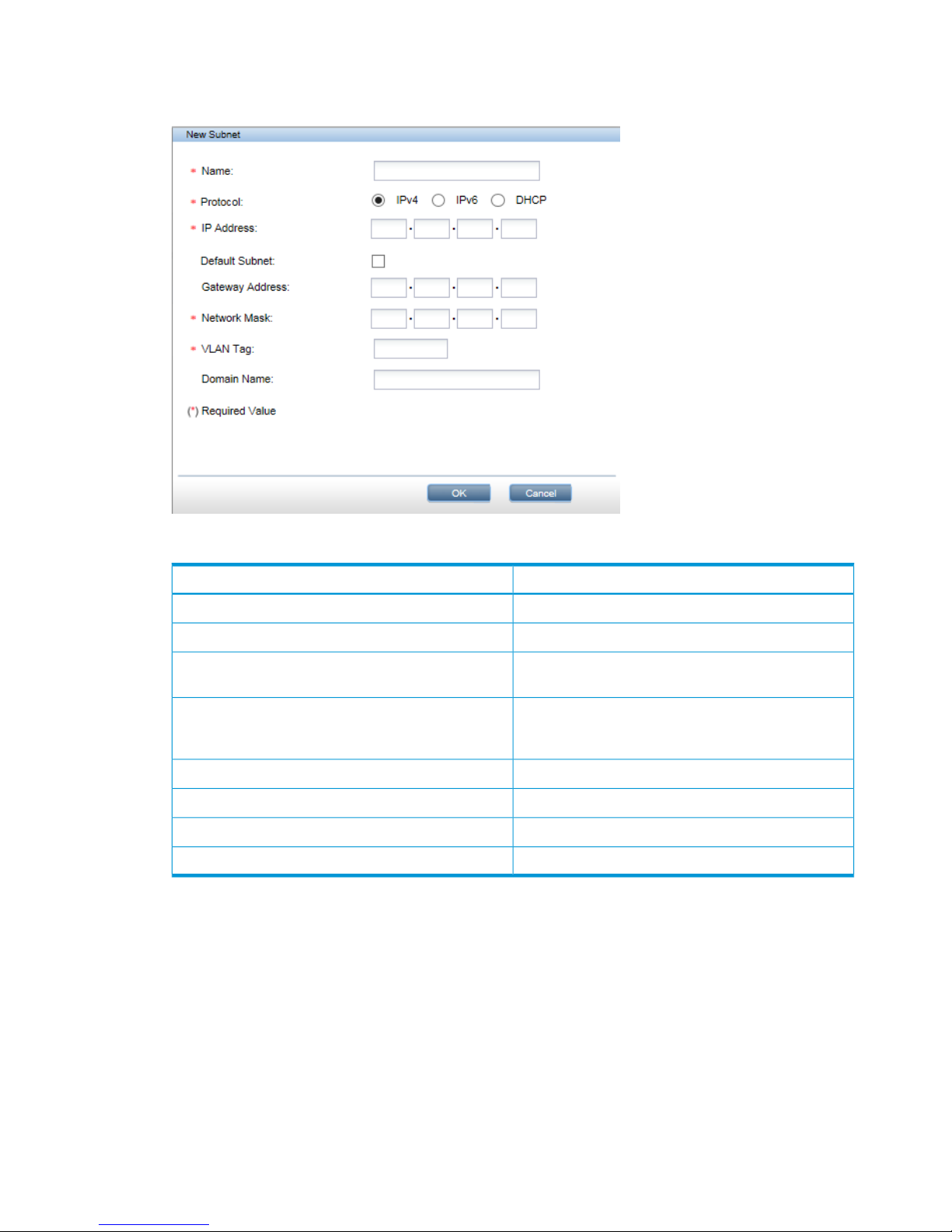
Step 3: Create Subnets
1. Select the Port Set and click Add in the Subnet section.
Table 7 Network Configuration New Subnet fields
DescriptionName
The name of the SubnetName
Select IPv4 or IPv6.Protocol
The IP address for the subnet, in the appropriate format
for the protocol selected.
IP address
When checked, this box indicates that this is the Subnet
that contains the default gateway. A default subnet
should be provided for both IPv4 and IPv6 networks.
Default Subnet
The network maskNetwork Mask (IPv4 only)
The network prefix in CIDR formatPrefix (IPv6 only)
The domain nameDomain Name
The VLAN tag ID (2 to 4096)VLAN tag
2. Provide the Subnet details listed in Network configuration subnet fields (page 56), and click
OK.
• For IPv4 Subnets select the IPv4 button and provide the relevant details.
• For IPv6 Subnets select the IPv6 button and provide the relevant details.
• DHCP Subnets may support both IPv4 and IPv6 protocols.
3. Repeat until all the Subnets for the selected Port Set have been defined.
• Each physical Port Set may be configured with one Subnet that uses the IPv4 protocol
and one Subnet that uses the IPv6 protocol.
• If the Port Set is VLAN enabled, it is possible to add a total of 128 VLAN Subnets. These
total values apply across the whole network configuration, not per Port Set.
• If DHCP is used , one IPv4 and one IPv6 subnet will be consumed.
56 Network configuration, how to use the StoreOnce GUI
Page 57

4. Click Save to save all configuration details.
Step 4 and 5: Validation and Activation
1. Click Validate to validate the network configuration. If there are any errors, the error message
will guide you to the parts of the configuration that need correcting. Make the necessary
changes, save them and click Validate again.
2. If validation is successful, you have two choices. The HP StoreOnce Management GUI will
prompt you to activate the new configuration immediately. Or you can save it and activate it
separately from the Network Configuration — Custom page.
NOTE: It is not possible to activate a new configuration if storage addition is in progress.
To edit a custom configuration
You cannot edit the current or the Factory_Default_Configuration. However, you can
edit any configuration in the Custom configuration list. if the StoreOnce CLI wizard was used to
configure the network at installation, there will be at least one custom configuration in the list,
net_wizard.
NOTE: Before activating an edited custom configuration, you may like to create a copy of the
current configuration and save it to a different name. Once current is overwritten it cannot be
restored.
1. Select the configuration that you wish to edit and click Edit.
2. Make changes to the editable fields, as appropriate, and click Save. Some examples are
described below.
To add a VLAN–enabled Port Set and VLAN Subnet
1. Select the configuration in the Custom Network Configuration list and click Edit.
2. In the Port set section, click Add.
3. Enter Port Set details, in exactly the same way as when creating a new configuration.
• Select the required 1 Gbit or 10 Gbit ports. Available ports are active for selection; ports
already assigned are greyed out.
• If multiple ports have been selected, select a Bond Mode, as appropriate. This should be
Mode 1 or Mode 4 for VLAN.
4. Be sure to check the VLAN Tagging Enable box and click OK.
5. In the Subnet section, click Add.
To edit a custom configuration 57
Page 58

6. Enter Subnet details, in exactly the same way as when creating a new configuration, and be
sure to add the VLAN tag ID. Click OK.
7. Save and validate the changes. If required, you can also activate the configuration at this
point.
To write protect or un-protect a configuration
Select the configuration in the Custom Network Configuration list and click Edit.
Click in the Protected checkbox to change its status and click Save.
Repeat this process to switch the status back to Un-protected.
58 Network configuration, how to use the StoreOnce GUI
Page 59

8 Completing the installation
This chapter describes common tasks required after installation.
• Set the time and date and NTP server, if this was not done as part of the system set
config wizard. See also Setting up time and date (page 59).
• Apply any licenses for additional capacity, replication, StoreOnce Catalyst or Security features,
if required. See Configuring licenses (page 60).
• Discover and add storage for any expansion shelves that have been added, see Expanding
storage (page 62).
• Understand how to access the StoreOnce Backup system over SFTP, see Accessing the
StoreOnce Backup system over SFTP (page 63).
• Install any software and firmware updates, if needed. See Software update process (page 64)
and Firmware update process (page 64).
• Configure Remote Support. See Configuring Remote Support (page 66).
• Configure SNMP, if required. See Configuring SNMP (page 72).
• Perform a configuration save. See Saving configuration file (page 72).
• If a Security license has been installed, save the encryption keystore. See (page 73).
• Reset the password for the HPresetpassword account and save the new password securely
offline. See Managing and resetting the password for the HPresetpassword account (page 73).
For other tasks, such as user account configuration, email configuration, and device configuration
for backup/replication targets using VTL, NAS or StoreOnce Catalyst refer to the HP StoreOnce
Backup system user guide.
Setting up time and date
NOTE: HP strongly recommends setting the time and date when configuring the network using
the system set config wizard. This section describes how to do this if you have not used the
wizard.
1. Open the puTTy (or other ssh) application and log into the StoreOnce CLI.
2. Make sure you know what the UTC time is and then set the system clock using the following
command:
time set utc <mm/dd/yyyy hh:mm:ss>
TIP: If defining an NTP server, still set UTC because this will result in a quick synchronization
with NTP.
3. Set the time zone using the following command:
time set timezone
You will be asked to select a continent/ocean and country as part of the command sequence.
4. If you have defined an NTP server, enter its IP address or FQDN using the StoreOnce CLI
command:
time add ntpserver <IP address or FQDN>
Setting up time and date 59
Page 60

5. You can check the configuration, as shown in the following example:
# time show config
NTP Server(s)
- — — — — — — ntp.mycompany.net
TimeZone : BST
UTC : 09/19/2012 12:37:40
LocalTime : 09/19/2012 13:37:40
NOTE: If configuring time manually or via an NTP server results in time moving backward, you
will be prompted to perform a system reboot.
Configuring licenses
Licensing requirements for StoreOnce hardware products
There are two types of license:
• Full license (not time limited)
• Instant on or Demo (time limited to 90 days): This allows you to try out licensable functionality
before paying for a full license for any of the features described below.
The HP StoreOnce Backup system licensing requirements are:
• All capacity expansion must be licensed. Each storage expansion kit contains a license that
must be loaded.
HP StoreOnce 4900 Backup: The correct number of licenses for additional storage must be
installed in the correct order. The 44TB Capacity Expansion Kit has a different license type
from the 60TB Capacity Expansion Kit. The StoreOnce Backup system requires licenses to be
installed in the following sequence: 5 x 44TB Capacity Expansion, 1 x 60TB Capacity
Expansion, 5 x 44TB Capacity Expansion.
• No licensing is required for VTL or NAS emulations.
• VTL and NAS replication requires a license on the target system.
• StoreOnce Catalyst devices require a license for backup and for copy, so licenses must be
installed on both origin and destination systems.
• Security features (Data at Rest Encryption, Data in Flight Encryption, and Secure Erase) require
a Security license.
Applying the Instant On license
NOTE: The Instant On license is sometimes called the Demo license.
The Instant On license is available for all StoreOnce Backup systems and is a single license that
enables two features, StoreOnce Catalyst and StoreOnce Replication, for a period of 90 days.
This allows customer to try some of the advanced features in StoreOnce units without having to
purchase a full licence in advance. The license must be activated as described in the next section.
NOTE: This license does not include capacity expansion nor the Security Pack.
To continue using these features, separate licenses must be purchased for StoreOnce Catalyst and
Replication and applied within the Instant-On period. If they are not, data is not lost but:
• Replication: Replication Target libraries will become read only.
• StoreOnce Catalyst: Catalyst jobs will fail.
60 Completing the installation
Page 61
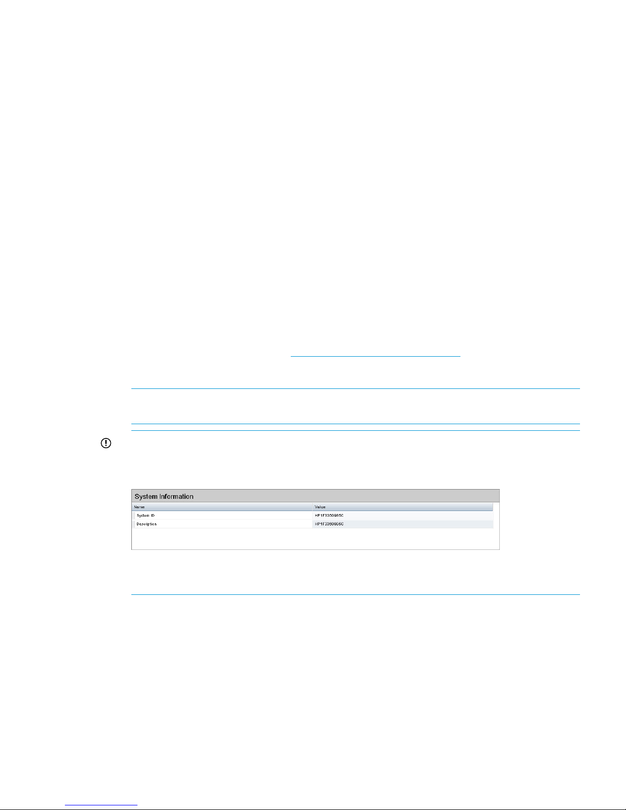
To apply an Instant On license
Use StoreOnce CLI commands as follows:
• license show to show the current license status
• license add demo to apply the 90–day license for all licensable features.
•
See the HP StoreOnce Backup system CLI Reference Guide for more information.
To apply a full license
Features that require a license include a license entitlement certificate with the hardware product.
This is either an electronic document provided at purchase, such as Replication, StoreOnce Catalyst,
Security (Data at Rest Encryption, Data in Flight Encryption, or Secure Erase), or a paper document
provided with a capacity upgrade kit. The document contains all information required to obtain a
unique License to Use (LTU) key. Obtain the key from the HP Licensing site by connecting to the
web address specified on the certificate and following the instructions. (Users without Internet
access may use the contact numbers provided with the entitlement certificate.)
You will be required to enter the product's serial number when requesting an LTU key.
The number you should use is either the System ID that can be found on the Device Configuration
page of the GUI or the Serial Number that can be found on the Status page of the GUI. The HP
licensing portal accepts the UUID with, or without, the leading “hp”.
1. Obtain the unique LTU key as instructed on the License Entitlement Certificate. This is normally
from the HP Licensing website at http://www.myhplicensing.hp.com. HP recommends saving
the license to a .DAT file. The file can also be emailed to the registered license owner's email
address, or Cut and Paste to copy it to a temporary file.
NOTE: A Quick Start guide to using the HP Licensing website is available from the Help link
at the top of the website page.
IMPORTANT: When redeeming licenses for replication and additional storage, HP Licensing
will ask you to provide a serial number. The number you should use is the System ID that can
be found on the Device Configuration page.
Do not use the warranty serial number that can be found on the server or tag attached to it.
Always use the Serial Number as displayed in the HP StoreOnce Management GUI.
2. If you save the LTU as a file, sftp it into the HP StoreOnce Backup system's repository
directory.
• Using Linux
sftp Admin@<IP_address>
cd repository
put <LTU>.DAT
exit sftp
• Using a Windows sftp client
Ensure the File Protocol is set to SFTP, not SCP.
Configuring licenses 61
Page 62

Login to the StoreOnce GUI as Admin.
Copy <LTU>.DAT to repository.
3. Verify the LTU is stored within the repository using StoreOnce CLI command: system show
repository.
Look for the <LTU>.DAT file.
4. Apply the license using one of the following StoreOnce CLI commands:
• license load <LTU>.DAT to load a license that has been saved as a file image. The
file image must exist in the Backup system's repository directory.
NOTE: If the license file contains a space in its name, the command should be license
load “<LTU>.DAT”. Here is an example of license file name that contains spaces: HP
StoreOnce 60_23702636.DAT. The command to load this file would be:
license load "HP StoreOnce 60_23702636.DAT"
• license add <license key string> to key in the license directly. If you used
email or a temporary file, copy and paste the string exactly as obtained from the HP
Licensing website. It is not advised to key in the LTU manually.
NOTE: The key is specific to the HP StoreOnce Backup system. It cannot be transferred.
5. To ensure that the license was applied successfully, run the StoreOnce CLI command:
license show
Expanding storage
NOTE: For a more detailed description of this process refer to the HP StoreOnce Backup system
Capacity Upgrade guide supplied with the expansion kit.
IMPORTANT: HP 4700 Backup systems only: Do not follow this process for the first storage shelf
because the StoreOnce Backup is delivered with the storage already expanded.
Be sure to apply the licenses for all kits before running the expansion process. All Upgrade Kits
that have been licensed are included in the expansion process.
1. Open the puTTy (or other ssh) application and login to the StoreOnce CLI as an Admin user.
2. Scan for the newly attached storage and create a new Logical Unit (LUN) on this storage using
the StoreOnce CLI command:
hardware discover storage
3. Monitor the status of the LUN creation process using the StoreOnce CLI command:
system show status
The following output is an example of the two commands; the values shown may not match
your appliance specific values.
# hardware discover storage
This command takes several minutes to complete execution.
storage discovery successfully completed
# system show status
Status
-----Formatted 15,070.76GB, Discovered 20,932.81GB to be added
62 Completing the installation
Page 63

Service Sets Status Notes
------------ ------ ----Set 1 Running
4. Once the discovery process is complete, run the following command in order to format the
storage LUN with file system segments:
hardware add storage
This command will expand the filesystem to use the storage. The process can take a long time
to complete and the new capacity will not be available until it is finished.
5. Monitor the expansion using the following command:
system show status
This command will return either of the following after an add command has been sent:
Adding X,XXXGB... or Formatted XXGB
The following output is an example; the values shown may not match your appliance specific
values.
# system show status
Status
-----Formatted 15,070.76GB
Service Sets Status Notes
------------ ------ ----Set 1 Running
Accessing the StoreOnce Backup system over SFTP
There are a number of occasions when you may need to access the HP StoreOnce Backup system
over SFTP:
• To transfer software update packages to the correct location in the StoreOnce folder structure.
• To access files that are generated and stored in the StoreOnce folder structure, such as the
support tickets (in the /tickets folder), software upgrades (in the /repository folder)
and the saved configurations (in the /config folder).
Figure 24 StoreOnce folder structure
Accessing the StoreOnce Backup system over SFTP 63
Page 64

Accessing the StoreOnce folders
Use an SFTP client to access the StoreOnce Backup system.
NOTE: There are a number of SFTP clients available on the internet. For example, FileZilla is a
free, open source SFTP client for Windows and Linux and can be downloaded from https://
filezilla-project .org.
• Using Linux
sftp Admin@<IP_address>
cd <folder_name>
Use the appropriate commands — examples are included in the following sections where
SFTP is used to carry out a specific task.
exit sftp
• Using a Windows SFTP client
Ensure the File Protocol is set to SFTP, not SCP or FTP.
Login to the HP StoreOnce Backup system as Admin.
Use the appropriate commands to perform the required tasks.
Software update process
IMPORTANT: Aalways refer to the Release notes for the most current information about installing
software updates.
Download the upgrade package from the Software Depot, https://h20392.www2.hp.com/portal/
swdepot/index.do. The name of the upgrade will be in the format <part_number>.rpm.
You will need an HP Passport account to download the RPM file, this can be created when they
first access the download website.
Software updates can only be performed through the StoreOnce CLI using the Admin user account.
Software updates are delivered to customers in the form of a single RPM image, which may contain
multiple rpms. Everything is updated in the same way, using the rpm package: the software, third
party components and the firmware for hardware components.
A software update is NOT an online process. Services will shutdown to perform the updates, so
the whole appliance will be offline for a period of time (see the release notes for details).
HP recommends carrying out a Firmware Check and Update immediately after a software update,
as described in the release notes.
Upgrading BIOS or hardware firmware components
Do not upgrade BIOS or hardware firmware components individually using downloads from the
HP Support website because currently supported firmware component updates are already
embedded within the StoreOnce software. Use either the StoreOnce GUI or the StoreOnce CLI to
implement BIOS and hardware firmware component checks and updates.
Firmware maintenance from the StoreOnce GUI
1. Select the Firmware page to view the firmware versions for hardware components, and to
update firmware versions if required.
The page contains the following tabs:
• Server: Contains hardware components for the server.
• Storage: Contains hardware components for all storage elements.
64 Completing the installation
Page 65

2. Click Scan to perform a check on the currently installed firmware versions for all components
associated to the selected node.
This will populate the firmware tabs. This may take several minutes to run.
NOTE: The scan will fail if a firmware update is already in progress.
3. Look for components that have a Recommended Action of either Upgrade or Downgrade. After
you have run Scan or Scan All, components will automatically be selected for upgrade or
downgrade.
NOTE: When the firmware updates are initiated, the backup devices will be taken offline.
Before performing this step, check that there are no outstanding backup jobs pending.
• If there are only one or two, click in the appropriate check box to select them and click
Update Selected.
• If there are many, click Update All. This will attempt to update all components that are in
the state where there is an update recommended; it will not try to update components
that do not need an update.
The Status field will show which components are being updated and which updates have
been completed.
4. When all updates are completed, a reboot may be required.
5. After the firmware has updated, HP recommends a cold reboot as follows:
• Power off the StoreOnce Backup from the Maintenance page.
• After the system has completely shut down, wait at least one minute before powering on
using the Power On button on the server(s).
NOTE: A cold reboot is required if the network card or storage controller card firmware has
been updated. For other components, it is acceptable to reboot the system using the Reboot
option on the Maintenance page.
Firmware maintenance from the StoreOnce CLI
Procedure 1
1. Run the StoreOnce CLI command to show the current status of firmware
# hardware show firmware <node|storage>
2. Check the Action column to see if any firmware needs upgrading.
IMPORTANT: Do not shutdown or reboot your system or any system component until step
5. Special instructions may apply. See step 5 for details.
3. Before upgrading firmware, stop service sets.
serviceset stop all to stop service sets and ensure that no jobs are running
Wait one minute and check that service sets have stopped.
service show status to verify that all service sets have stopped. It may take up to one
minute for all service sets to stop.
# service show status
Service Set 1 Status
------------- ------Overall : Not Running
#
Upgrading BIOS or hardware firmware components 65
Page 66

4. Use the hardware update firmware <node|storage> command, as required. For
example, there may be instances where replacement hardware may need a firmware
downgrade to bring it in line with the supported firmware version of the installed StoreOnce
software on the system being maintained.
The command will be applied across all server components or across all storage components.
hardware update firmware <node|storage>
5. After the firmware has updated, HP recommends a cold reboot as follows:
• Power down the node(s) using the StoreOnce CLI command:
system shutdown
• After the system has completely shut down, wait at least one minute before powering on
using the Power On button on the server(s).
NOTE: A cold reboot is required if the network card or storage controller card firmware has
been updated. For other components, it is acceptable to reboot the system using the StoreOnce
CLI command:
system reboot
Configuring Remote Support
IMPORTANT: The warranty serial number is the serial number for the bundled product. This is
not always the same as the serial number that is shown on the individual component. The products
are supplied with labels that contain product numbers and serial numbers for warranty, and these
warranty serial numbers are the numbers that should be used when contacting HP for support. The
HP Remote Support pages provide an easy way of recording the warranty entitlement information
within the StoreOnce GUI.
Before configuring Remote Support
IMPORTANT: The use of this feature requires the customer to provide a proxy server path to the
internet, in order for the StoreOnce Backup system to communicate back to HP Support.
1. Remote Support is not compatible with other HP Support Tools, such as IRS. Decide which
support option is appropriate for your environment.
• If you are already using IRS and wish to use Remote Support, you can either disable
SNMP on the Backup system (if it is not needed for other non-HP tools) or disable remote
support for StoreOnce on the IRS server. Consult your IRS documentation or HP Support
for further details.
• If you are using only non-HP tools to monitor SNMP messages, there is no need to disable
SNMP on the StoreOnce Backup system. There is no conflict with StoreOnce Remote
Support
2. Alerts are transmitted over port 443. If the Data Center environment does not allow internet
access, you cannot use Remote Support.
3. The details of the HP Remote Support server that will receive the alerts from the StoreOnce
Backup system are provided by the StoreOnce GUI. You need to enter the details of the proxy
server that will be used to enable internet access between the StoreOnce Backup system and
the HP Remote Support server.
66 Completing the installation
Page 67

4. Determine what customer technical contact details should be used by HP Support.
5. Make sure you have access to the warranty serial numbers and product numbers (found on
the product labels) and entitlement details for the server node in the system to be configured.
SAID or CarePackID extended warranties may be purchased for the HP StoreOnce Backup
system or hardware components.
NOTE: It is important to distinguish between the warranty serial numbers and the serial
numbers on individual components within the product. HP Remote Support requires the warranty
serial numbers, see the next section for a more detailed description.
General procedure for setting up Remote Support on the HP StoreOnce Management
GUI
Remote Support is a standard feature that is enabled and available to all users.
If you do not configure Remote Support, you will be prompted to do so every time you log onto
the HP StoreOnce Management GUI. To prevent this, you should go to the Remote Support pages
on the HP StoreOnce Management GUI and either configure it, or select No Support, as appropriate.
NOTE: The examples in this section are generic; they are not intended to be product specific,
merely to illustrate the overall procedure.
For information about using specific GUI pages to configure Remote Support, see the appropriate
sections in the HP StoreOnce Backup system user guide. These sections also contain example
screenshots.
1. Go to the Remote Support pages of the StoreOnce Management GUI.
2. Click Modify. Select Passive: Automatically send log files to HP and provide the details for the
proxy server that enables internet access for Remote Support. If required for the network
environment, check the Enable Authentication box and provide authentication name and
password details. Click OK.
NOTE: Details for the Enterprise Server (the server that will receive the event messages) are
provided by the StoreOnce Backup system and should not be edited.
3. Select Customer Information. Click Modify and enter technical contact details for the customer
site. HP Support will use this information to provide feedback and instructions on resolving
any issues. Information is required for all fields marked with an asterisk.
4. Select Entitlement. Check to see if Warranty Serial Number and Warranty Product Number
fields are populated.
5. Where possible, the systems will extract the warranty serial information from the BIOS. If the
fields are populated, no further action is required. Warranty serial number information present
in the BIOS cannot be modified. Go to step 7.
However, if the system has not been able to extract warranty information from the BIOS, click
Modify and provide the warranty details.
Go to the StoreOnce Backup system and search for the warranty sticker. Be careful to distinguish
between the component serial number and the warranty serial number. Instructions for locating
these numbers on specific products can be found in Locating warranty information (page 68).
The following is an example sticker on a server component. Note that the Product Number is
in a 9-digit numerical format. This is not a StoreOnce product number.
Configuring Remote Support 67
Page 68
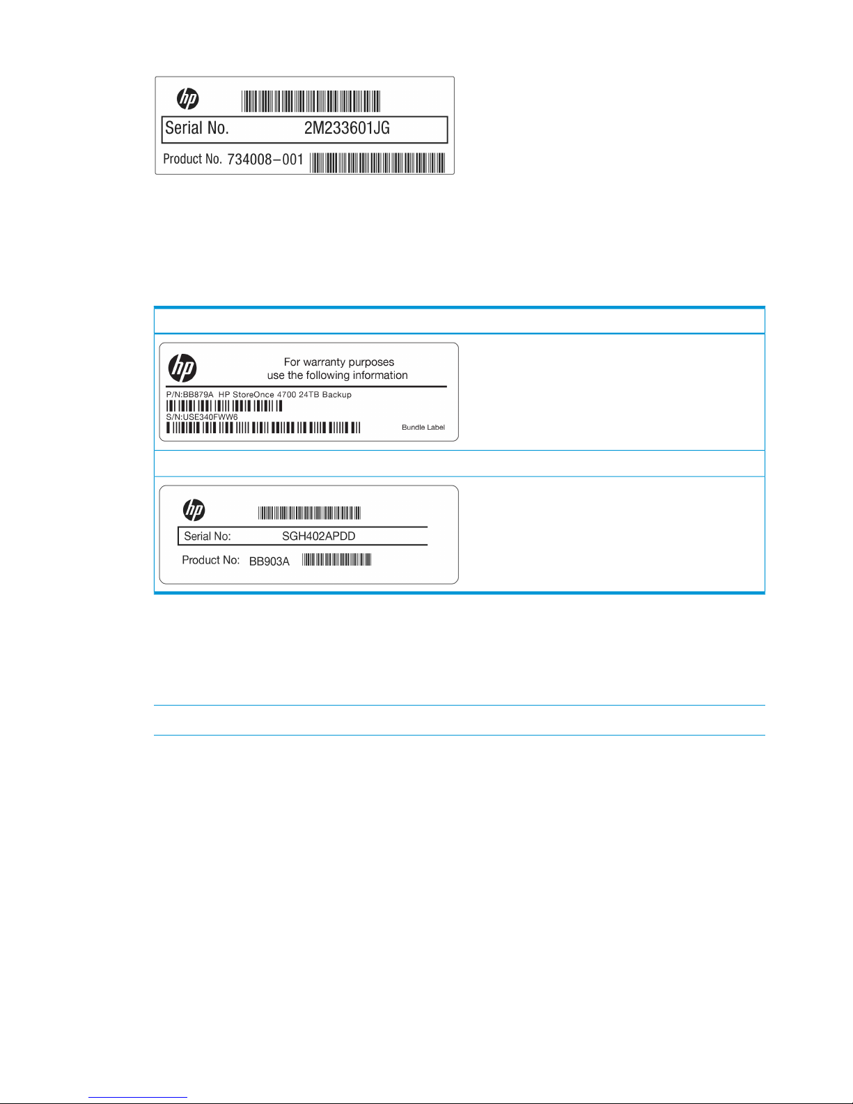
Figure 25 Example component serial number (not to be used)
The warranty serial tag is on a separate label, which may have a number of different layouts.
The key thing is that the Product number is in a 6-character format, that matches one of the
StoreOnce product names described in the next sections.
The following examples are taken from HP StoreOnce 4700 and 4900 Backup systems.
Table 8 Example StoreOnce warranty labels (to be used)
HP StoreOnce 4700
HP StoreOnce 4900
6. Go back to the HP StoreOnce Management GUI, click Modify and enter this warranty serial
number into the Entitlement page under Warranty serial number. Also enter the Product Number
in Warranty Product Number.
7. Select Status to confirm that everything has been configured. There should not be an X against
any field on the screen.
NOTE: A missing serial number will prevent a test event being sent.
8. Click Send Test Event on the Remote Support page.
9. Call HP support and ask to verify a remote support event has been received.
The HP Support person will check on the database portal that the event has been received
and will also verify that warranty/serial/part numbers are valid and under warranty (or have
valid care packs).
This completes Remote Support verification.
Locating warranty information
With StoreOnce software version 3.13.0 and later, the warranty information for HP Remote Support
relates to the base product and not to additional storage. In many cases, the warranty details are
embedded in the system BIOS and the user does not have to provide the information. The following
table describes where to look if the system is unable to extract these details automatically.
68 Completing the installation
Page 69

Table 9 Locating warranty information
NotesWarranty Serial NumberWarranty Product NumberProduct Description
Additional storage (BB881A)
may be added to this
Locate by looking at the
labels:
Either at the front right and
back of the server
BB879AHP StoreOnce 4700,
consists of a server and
storage array product but there is currently
no facility for recording
Or the back left and back of
the first storage enclosure
warranty information for the
additional storage.
Additional storage (BB881A
or BB909A) may be added
Locate by looking for the
sticker at the front right of
the server.
BB878AHP StoreOnce 4500,
consists of a server with 12
disks to this product but there is
currently no facility for
recording warranty
information for the
additional storage.
No additional storage
supported.
Locate by looking for the
sticker at the front left of the
server.
BB877AHP StoreOnce 2700,
consists of a server with 4
disks
Additional storage (BB911A)
may be added to this
Locate by looking for the
sticker at the front right of
the server.
BB910AHP StoreOnce 2900 consists
of a server with 6 disks.
product but there is currently
no facility for recording
warranty information for the
additional storage
Warranty details - HP 4700
The base HP StoreOnce 4700 model, BB879A, consists of a server with two OS disks and a
12–disk storage array. If possible, the warranty details required for the Warranty serial number
are read from BIOS, so that the Entitlement page is populated automatically. One Capacity Upgrade
kit containing 12 disks, BB8811A, is available and up to seven may be added to the base system,
but these are not recorded on the Remote Support pages.
Configuring Remote Support 69
Page 70

Figure 26 HP StoreOnce 4700 Backup bundled warranty serial numbers
Product Name on GUIDescription
HP StoreOnce 4700 Backuphead server (OS disks only) (BB879A)1
Not shown on GUI (was D2600 prior to 3.13.x)first storage array (12 disks) (BB879A)2
Not shown on GUI (was D2600 prior to 3.13.x)additional storage arrays (BB881A)3 to 9
Items 1 and 2 are covered by the same warranty serial number; each additional enclosure has a unique warranty
serial number but that is not recorded on the StoreOnce GUI.
Warranty details - HP 4500
The base HP StoreOnce 4500 model, BB878A, consists of a server with 12 disks. If possible, the
warranty details required for the Warranty serial number are read from BIOS, so that the Entitlement
page is populated automatically. Two Capacity Upgrade kits containing 12 disks, BB8811A and
BB909A, are available and up to three may be added to the base system, but these are not
recorded on the Remote Support pages.
70 Completing the installation
Page 71
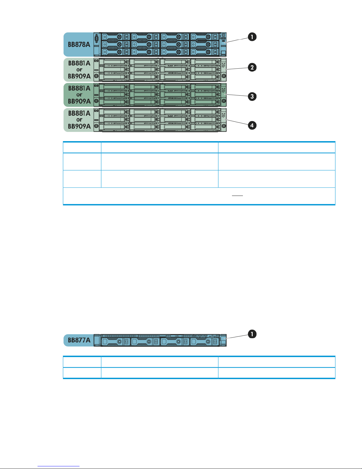
Figure 27 HP StoreOnce 4500 Backup bundled warranty serial numbers
Product Name on GUIDescription
HP StoreOnce 4500 Backuphead server (2 x OS + 10 x storage disks)
(BB878A)
1
Not shown on GUI (was D2600 prior to 3.13.x)additional 12–disk storage arrays (BB881A or
BB909A)
2 to 4
The warranty serial number for Item 1 is recorded on the Storeonce GUI. Each additional enclosure has a unique
warranty serial number but that is not recorded on the StoreOnce GUI.
Warranty details — HP 2900
The base HP StoreOnce 2900 model, BB910A, consists of a server with 6 disks. The warranty
details required for the Warranty serial number are read from BIOS, so that the Entitlement page
is populated automatically. The customer does not need to carry out any further action. A Capacity
Upgrade kit containing a further six disks, BB911A, is available, but this is not recorded on the
Remote Support pages.
Warranty details - HP 2700
The base HP StoreOnce 2700 model, BB877A, consists of a server with 12 disks. Where possible,
the warranty details required for the Warranty serial number are read from BIOS, so that the
Entitlement page is populated automatically. The customer does not need to carry out any further
action. Capacity expansion is not supported for this product.
Figure 28 HP StoreOnce 2700 Backup bundled warranty serial numbers
Product Name on GUIDescription
HP StoreOnce 2700 Backuphead server with storage (BB877A)1
Configuring Remote Support 71
Page 72

Configuring SNMP
NOTE: StoreOnce software version 3.13.x and later allows the user to configure SNMP from
the StoreOnce GUI. Refer to the StoreOnce Backup system user guide for further details.
This feature enables an HP StoreOnce Backup system to act as a Network Element in an SNMP
network so that it can communicate effectively with Network Management Stations using SNMP
(Simple Network Management Protocol). You can also use the StoreOnce CLI to enable this feature
and configure various settings, as described below.
The StoreOnce implementation of SNMP is compatible with and has been tested with HP System
Insight Manager (HP-SIM). It supports SNMPv1 and SNMPv3, which provides authentication.
1. Open the puTTy (or other ssh) application and log into the StoreOnce CLI as an Admin user.
2. Enter the following command to enable SNMP.
snmp enable
3. The following example is a basic example to capture alerts that are broadcast to the public
community. See the HP StoreOnce CLI Reference Guide for more detailed information.
snmp add trapsink mysimserver.mycompany.local trap-community public
events alert
Network Management systems and MIBs
The MIBs, Management Information Bases, used to represent the information handled by the HP
StoreOnce Backup system are called SEMI-MIB.mib and TRAP-DESTINATIONS-MIB.mib. These
must be downloaded and registered with the Network Management application on the host, so
that information from the StoreOnce Backup system can be transmitted to and interpreted by the
Network Management host.
To download the MIBs, go to the HP Support website at http://www.hp.com/support and search
for your StoreOnce Backup product. Select the Software and driver downloads option and OS
Independent for the operating system. The MIBs are included under the OS Independent Downloads.
There are typically three stages to setting up the Network Management application for use with
the HP StoreOnce Backup system:
1. Register SEMI-MIB.mib and TRAP-DESTINATION-MIB within the base of MIBs supported by
the Network Management application.
2. Update the existing system type database with the new system type for the HP StoreOnce
Backup system, based on the unique system object identifier.
3. Discover the HP StoreOnce Backup system under the Network Management application.
NOTE: For further information about implementing these three stages, refer to the MIB release
notes and to the documentation supplied with the Network Management application.
Saving the configuration
NOTE: It is strongly recommended to save the configuration whenever you make changes to it.
1. Open the puTTy (or other ssh) application and login to the StoreOnce CLI as an Admin user.
Save the configuration using the StoreOnce CLI command:
config save devices
2. Using sftp protocol and an application, such as filezilla, copy the following files from
/config to your local machine.
• devconfig_<cluster ID and serial number><date and time>.zip
• devconfig_<cluster ID and serial number><date and time>.txt
72 Completing the installation
Page 73

Restoring the configurations
The configuration consists of two parts:
1. A set of instructions in the form of a text file, devconfig<timestamp>.txt, for the user
to manually restore some of the network and device management configuration settings that
cannot be automatically restored.
2. A zip file, devconfig<timestamp>.zip, containing StoreOnce device configuration
settings that automatically restore configuration settings that have been created for StoreOnce
VTL, NAS, Catalyst, Replication and housekeeping functions.
IMPORTANT: If settings in the text file need to be restored, the manual restore should always be
carried out before the automatic restore.
See the HP StoreOnce Backup system user guide for more information about saving and restoring
configurations.
Saving the encryption keystore
Data at Rest and Data in flight encryption use encryption keys. Encryption keys are written to a
key store which should be backed up and saved securely offsite in case the original key store is
corrupted. However, be sure to keep only the latest version of the key store.
The StoreOnce CLI command config save keystore that backs up the key store, also encrypts
it, ensuring that it can only be decrypted by the HP StoreOnce backup system, should you need
to restore it.
NOTE: Data at rest and Data in flight encryption are two of three security features that can be
applied using the Security license (which must be purchased and applied in the normal way).
Managing and resetting the password for the HPresetpassword account
If administrator credentials are lost, the administrator password can be reset through the hidden
user account “HPresetpassword”. This account is password protected and is only accessible from
the StoreOnce console and StoreOnce CLI. HP recommends you change the HPresetpassword
password after installation and store it in an offline password security tool.
This account is not accessible via a remote ssh session.
IMPORTANT: It is strongly recommended that the password for the HPresetpassword account is
changed immediately after installation. The new password should be strong and memorable.
To change the password for the HPresetpassword account
1. Gain access to the local system console either using a locally attached USB keyboard and
Monitor or via the iLO remote console.
2. At the Login prompt type:
HPresetpassword
3. When prompted for the password enter:
hpresetpassword
4. Once logged in a list of available commands will be presented.
reset: Reset the 'Admin' password to 'admin'
manage: Change the 'HPresetpassword' user's password
help: List available commands
exit: Log out
Saving the encryption keystore 73
Page 74

5. Run the command manage to change the password for the HPresetpassword user. At the
prompts provide:
• (current) UNIX password: the default at installation is hpresetpassword
• New UNIX password: the new password should be strong and memorable; it will not
be accepted if it is weak, for example a dictionary name
• Retype new UNIX password:re-enter the new password to confirm it
6. Type exit to log out.
7. Store the new password securely in an offline Password Security tool.
To reset the password for the local Admin user to default
1. Gain access to the local system console either using a locally attached USB keyboard and
Monitor or via iLO remote console.
2. At the Login prompt type: HPresetpassword
3. When prompted for the password enter the current password. The default is hpresetpassword,
but if you are following best practices you will have changed this after installation.
4. Once logged in a list of available commands will be presented.
5. Type reset. This will immediately reset the default password of the Admin user to admin.
6. Type exit to log out.
74 Completing the installation
Page 75

9 Fibre Channel installation and configuration
VTL library emulation and StoreOnce Catalyst are supported on Ethernet and Fibre Channel. NAS
is not supported on Fibre Channel. The StoreOnce Management Console and some of the other
StoreOnce features, such as replication, always require an Ethernet connection. When using FC
to back up hosts, you should still connect to an Ethernet port.
Fibre Channel is available with HP StoreOnce 4500 and 4700 Backup systems.
Fibre Channel connection
The HP StoreOnce Backup system is supplied with the correct FC cards pre-installed, if your product
supports FC connection. It does not include FC cables.
1. Connect to the appropriate SAN port, as described in the Cabling instructions earlier in this
guide..
2. Use a FC Multimode 50/125 (preferred) or 62.5/125 cable to connect the port(s) on the FC
card in the HP StoreOnce Backup system to the Fibre Channel Switch.
3. The switch must have a multi-mode transceiver that supports speeds of 8Gbs (preferred), 4Gbs
or 2Gbs.
4. Use the StoreOnce Management GUI, as described below to configure for use with VTL library
devices and StoreOnce Catalyst, respectively.
5. Use the StoreOnce Management GUI to find out the WW port and node names for use in
zoning. The WW names for VTL devices are on the VTL-Libraries-Interface Information tab.
The WW names for FC devices are on the StoreOnce Catalyst-Fibre Channel Settings tab
StoreOnce Catalyst over Fibre Channel
All configuration is from the StoreOnce Catalyst-Fibre Channel Settings tab.
Fibre Channel Settings tab
If StoreOnce Catalyst over Fibre Channel is enabled, the Fibre Channel Settings tab is available.
StoreOnce Catalyst over Fibre Channel functions in the same way as standard StoreOnce Catalyst
(over Ethernet). The backup application will not perceive a difference. However, some configuration
is required to set up the backup and restore connections between the ports on the HP StoreOnce
Backup system and the ports on the client servers. This is done using the Fibre Channel Settings
tab.
NOTE: This tab is only available if your HP StoreOnce Backup system supports Fibre Channel.
Fibre Channel connection 75
Page 76

Initial configuration
Please refer to the HP StoreOnce Backup system Installation and Configuration guide for cabling
instructions and zoning recommendations. The following process describes the steps to complete
configuration.
1. Go to the Fibre Channel Settings tab and, in the bottom section of the screen (Devices), locate
the World Wide Name information for each port on the StoreOnce Backup system. This is the
information that you need to zone the client with the StoreOnce Backup system.
2. Also look at the Identifier Name in the top section of the screen. This is the FC address of the
StoreOnce Backup system and is used to identify the StoreOnce Backup system in the backup
application. It is in the format CoFC-<device-id>; if preferred, you may provide an Identifier
Alias, which will be easier to identify from the backup application.
3. The Target Ports section in the center of the screen is identical to the settings that you can
configure for VTL target devices over FC. The default values are recommended, but you may
edit Speed and Topology.
NOTE: These Fibre Channel settings apply to the whole appliance and can also be edited
in the StoreOnce VTL section of the GUI, if you are backing up to StoreOnce VTL library target
devices over Fibre Channel. Port Speed or Topology settings, defined on either page, apply
to all target devices being backed up over Fibre Channel.
4. In the Devices section locate the Number of Logins and Devices per Initiator Port for each port.
These values determine the number of concurrent backup and restore connections allowed on
each FC port on the HP StoreOnce Backup system.
• The Number of Logins defines the number of client-side ports that are zoned to be able
to connect to that port on the StoreOnce Backup system. This cannot be edited.
• The Devices per Initiator Port value determines the number of backup and restore
connections that are allowed — for each client login — to that port on the StoreOnce
Backup system. This value should be increased if multiple concurrent backup streams are
required. Note that the maximum allowed is 64.
76 Fibre Channel installation and configuration
Page 77

NOTE: On Linux systems, it is possible that a client HBA port can open multiple concurrent
StoreOnce Catalyst over Fibre Channel connections to a target StoreOnce Fibre Channel port and
therefore it is sufficient to have a device count of 1. On Windows and HP-UX, this is not possible.
The number of devices per initiator port should be increased when multiple backup streams are
required so that multiple LUNs are presented to the client.
The number of paths available to a particular client is calculated as:
number of client ports zoned * number of StoreOnce node ports zoned *
devices per initiator port
Table 10 Example relationships between devices per initiator port and number of connections on
Windows and HP-UX
Number of concurrent
backup and restore sessionsDevices per Initiator port
HP StoreOnce Backup
systemClient-side
414 ports1 port zoned to
814 ports2 ports zoned to
6484 ports2 ports zoned to
1642 ports2 ports zoned to
Fibre Channel with VTL
There are three StoreOnce GUI screens that relate to FC with VTL.
• If required, the administrator may configure the port speed or topology from the VTL-Fibre
Channel Settings tab. The default settings are recommended.
NOTE: These Fibre Channel settings apply to the whole appliance and can also be edited
in the StoreOnce Catalyst section of the GUI, if you are backing up to StoreOnce Catalyst
target devices over Fibre Channel. Port Speed or Topology settings, defined on either page,
apply to all target devices being backed up over Fibre Channel. Therefore, any changes here
will also apply to StoreOnce Catalyst target devices over Fibre Channel and vice versa.
• When the user creates a library, using the VTL-Libraries-Create function, they specify which
FC ports it will use.
• The world wide names for the ports can then be found on the VTL-Libraries-Interface Information
tab.
Fibre Channel with VTL 77
Page 78
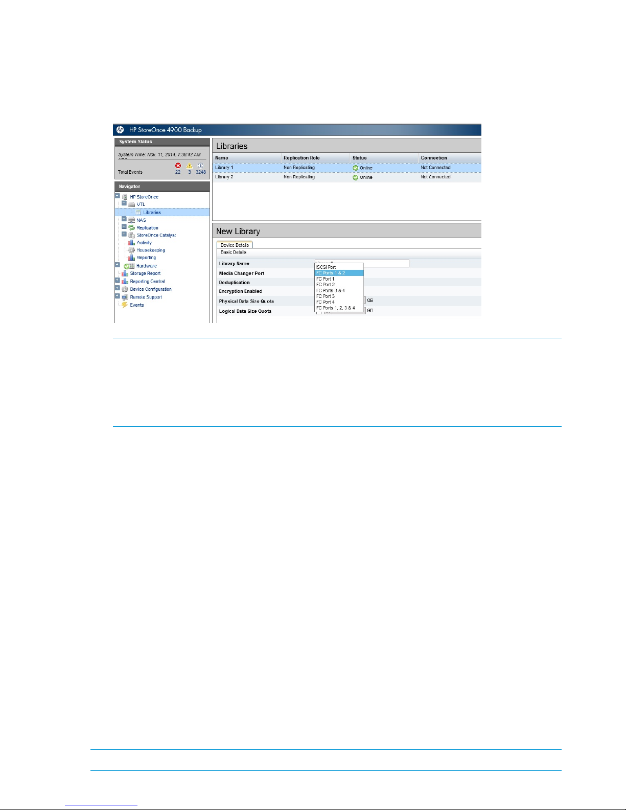
Creating a FC VTL library
1. When you use the StoreOnce GUI or CLI to create the library or Catalyst store device, select
one of the FC ports. The following example shows the Port drop-down in the StoreOnce GUI
for a model with two FC cards. For information about the other fields, see the HP StoreOnce
Backup system User Guide or online Help.
NOTE: When creating a FC library, you may select individual ports, FC ports 1&2 or FC
ports 3&4, or all four FC ports (if four ports are available). When four ports are available,
be aware that Port 1 and port 3 are on the first FC card; port 2 and port 4 are on the second
FC card, so it is important to ensure that the system has been cabled correctly when connecting
to the FC SAN. If you select one of the combined port options, both FC cards must be
connected.
2. Configure zones on the FC Fabric/Switch, if required. WW names for each library can be
found on the Interface Information tab.
3. The library device(s) should now be visible to the host. It may be necessary to perform a system
re-scan.
Drive port assignment for StoreOnce Backup systems
Drives can only appear on one port, so when you choose a combination of ports, the library
robotics are presented across all of the ports selected but the drives are automatically distributed
evenly across the ports to ensure best performance and failover. After creating the library, it is
possible to change the drive assignments using the edit function on the Interface Information tab
for the selected library. See the HP StoreOnce Backup system user guide for more details..
If you choose to present the VTL to FC Ports 1 &2 or FC Ports 3&4, the following happens. For this
example, Ports 1&2 are selected.
• The robot is presented to both Port1 and Port2.
• 50% of the configured drives are presented to Port1 and the other 50% to Port2 (this can be
changed if required using the edit function on the Interface Information tab for the selected
library. See the HP StoreOnce Backup system user guide for more information.).
• With this configuration in the event of a Fabric Failure – the robot and 50% of the drives are
available for backup.
• The disadvantage of this feature is that only a single 8Gb FC link is available for backups to
that library.
NOTE: If you choose to put the library on all four FC ports, it will put all the drives on Port 1.
78 Fibre Channel installation and configuration
Page 79

Zoning
Zoning is only required if a switched fabric topology is used.
Due to complexities in multi-hosting tape devices on SANs, it is best to make use of zoning tools
to help keep the backup/restore environment simple and less susceptible to the effects of changing
or problematic SANs.
Zoning provides a way for servers, disk arrays, and tape libraries to only see what hosts and
targets they need to see and use. The benefits of zoning include but are not limited to:
• Limiting unnecessary discoveries on the HP StoreOnce Backup system.
• Reducing stress on the HP StoreOnce Backup system and its library devices by polling agents.
• Reducing the time it takes to debug and resolve anomalies in the backup/restore environment.
• Reducing the potential for conflict with untested third-party products.
Zoning may not be necessary for small or simple configurations. Typically the bigger the SAN is,
the more zoning is needed. HP recommends the following for determining how and when to use
zoning.
• Small fabric (16 ports or less)—may not need zoning.
• Small to medium fabric (16 - 128 ports)—use host-centric zoning. Host-centric zoning is
implemented by creating a specific zone for each server or host, and adding only those storage
elements to be used by that host. Host-centric zoning prevents a server from detecting any
other devices on the SAN or including other servers, and it simplifies the device discovery
process.
• Disk and tape on the same pair of HBAs is supported along with the coexistence of array
multipath software (no multipath to tape or library devices on the HP StoreOnce Backup system,
but coexistence of the multipath software and tape devices).
• Large fabric (128 ports or more)—use host-centric zoning and split disk and tape targets.
Splitting disk and tape targets into separate zones prevents the HP StoreOnce Backup system
from discovering unnecessary disk controllers. For optimal performance, where practical,
dedicate HBAs for disk and tape.
NOTE: Overlapping zones are supported.
NOTE: The HP Brocade SAN Switches support NPIV natively but the Cisco SAN Switches require
that it be turned on for each port used.
Zoning 79
Page 80

10 Configuring backup servers to work with HP StoreOnce
This chapter describes how to configure Tape drivers and iSCSI on Windows backup servers. If
working in a Linux or UNIX environment, refer to the separate HP StoreOnce Backup systems Linux
and UNIX Configuration guide.
In this chapter:
• Configuring media servers to use StoreOnce Catalyst (page 80)
• Configuring Data in Flight encryption on Windows media servers (page 80)
• Driver installation (VTL only) (page 89)
• iSCSI Initiator (VTL only) (page 90)
Configuring media servers to use StoreOnce Catalyst
With HP Data Protector the StoreOnce deduplication engine is embedded in the HP Data Protector
Media Agent. No additional plug-ins are required.
In Symantec products HP has developed an OpenStorage (OST) Plug-in to NetBackup and Backup
Exec that creates the interface between Symantec products and the StoreOnce Catalyst store. This
software is available free and must be installed on all media servers that will be used to back up
to the StoreOnce Backup system.
The software, including documentation, can be downloaded from: https://h20392.www2.hp.com/
portal/swdepot/index.do.
Search for StoreOnce.
The search result includes the StoreOnce System Software for all products, VSA evaluation files,
and QR images for all hardware platforms, plus a link to StoreOnce Free Software. Click on
StoreOnce Free Software to access SEM, the OST plug-ins and the RMAN plug-in. Follow the
instructions included in the download to install the plug-ins.
Configuring Data in Flight encryption on Windows media servers
NOTE: Data in flight encryption is supported for backup to StoreOnce Catalyst target devices
and for Catalyst copy between StoreOnce Backup systems. It is not supported for backup to NAS
or VTL target devices, but is supported for replication between StoreOnce Backup systems.
The following procedure describes how to configure Windows Server 2008 R2 and 2012 for use
with StoreOnce Data in Flight encryption.
For instructions on configuring encryption on the StoreOnce Backup system, see Adding encryption
to StoreOnce Backup system (page 50). For instructions on configuring encryption on Linux see
the HP StoreOnce Linux and UNIX Configuration guide.
NOTE: The settings for key lifetimes can have an impact on the performance of the data in flight
encryption links. If the lifetime values are set to low values, then there is a risk of low performances
or even failures of the backup jobs. It is recommended, that these values are set sufficiently high
to allow the backup jobs to run as well as maintain the security of the data being transferred. The
default Windows setting of 480 minutes is sensible.
80 Configuring backup servers to work with HP StoreOnce
Page 81
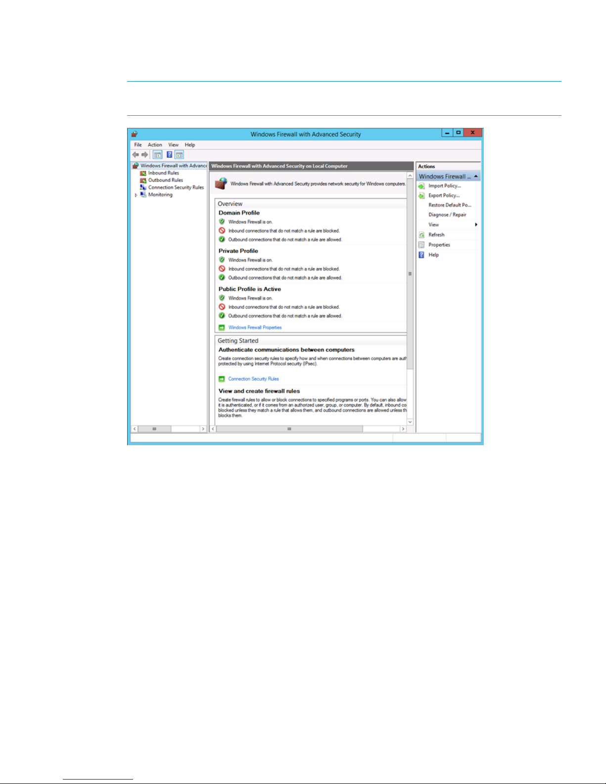
1. Open Windows Firewall with Advanced Security.
Go to Control Panel > System and Security > Administrative Tools > Windows Firewall with
Advanced Security.
NOTE: On Windows Server 2008 go to Server Manager -> Configuration -> Windows
Firewall with Advanced Security.
2. In the left hand navigation tree right click on Windows Firewall with Advanced Security and
select Properties.
Configuring Data in Flight encryption on Windows media servers 81
Page 82
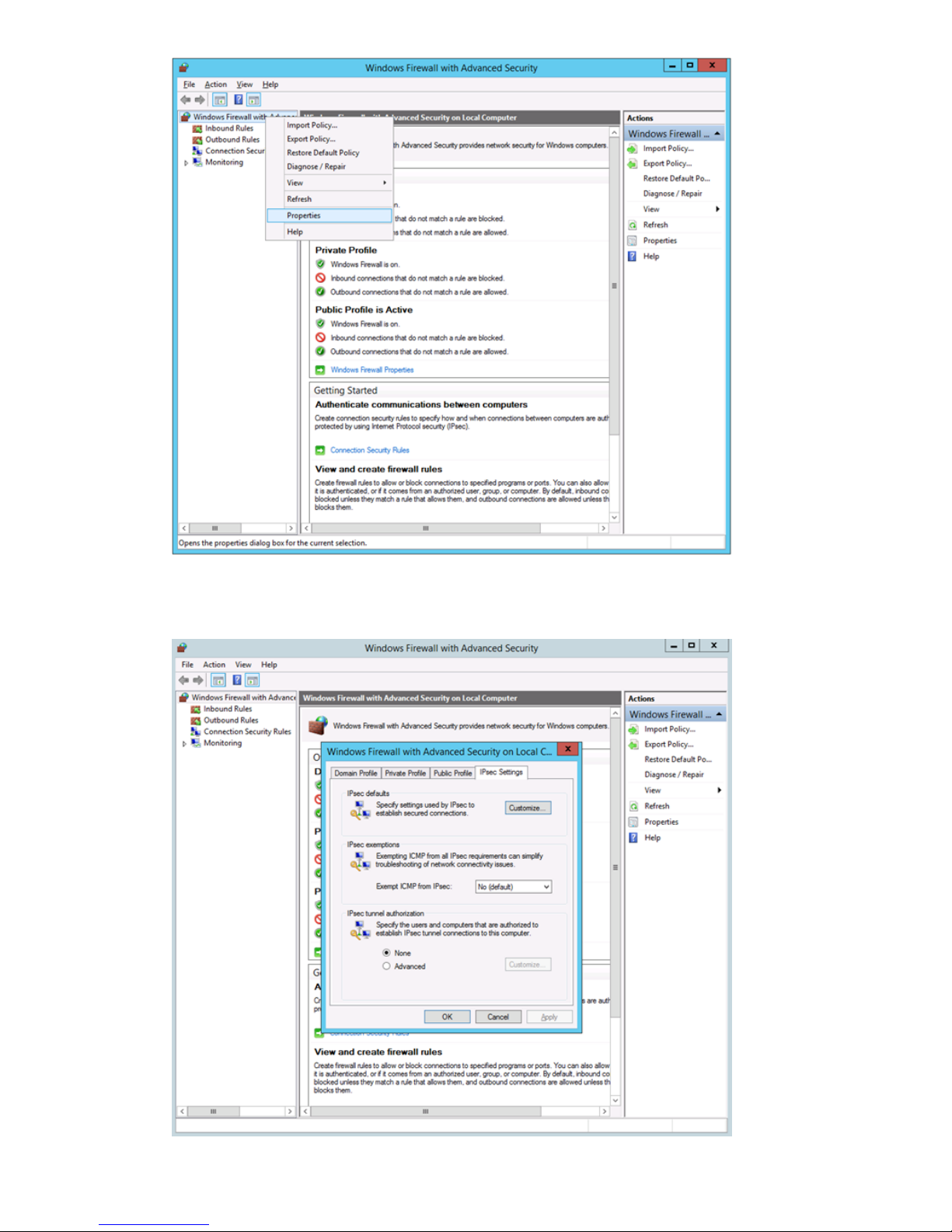
3. To make sure the firewall is switched on for the profile on which your network interface is
running go to the IPSec Settings tab.
82 Configuring backup servers to work with HP StoreOnce
Page 83

4. Under IPsec defaults click Customize.
5. Under Key exchange (Main Mode), select Advanced and click Customize.
6. Under Key Lifetimes, set Minutes to 480. Click OK
Configuring Data in Flight encryption on Windows media servers 83
Page 84

7. Under Data Protection (Quick Mode), select Advanced.
8. Click Customize. Under Data Integrity algorithms and Data Integrity and Encryption Algorithms,
select a protocol and click Edit.
9. Under Key lifetimes set the value of KB to 100,000,000 and click OK.
84 Configuring backup servers to work with HP StoreOnce
Page 85

10. Click OK three times to close the Properties boxes and return to the main Windows Firewall
with Advanced Security window.
11. In the left hand navigation tree first click and then right click on Connection Security Tools.
12. Select "New Rule.
13. For Rule Type select Server-to-server.
Configuring Data in Flight encryption on Windows media servers 85
Page 86
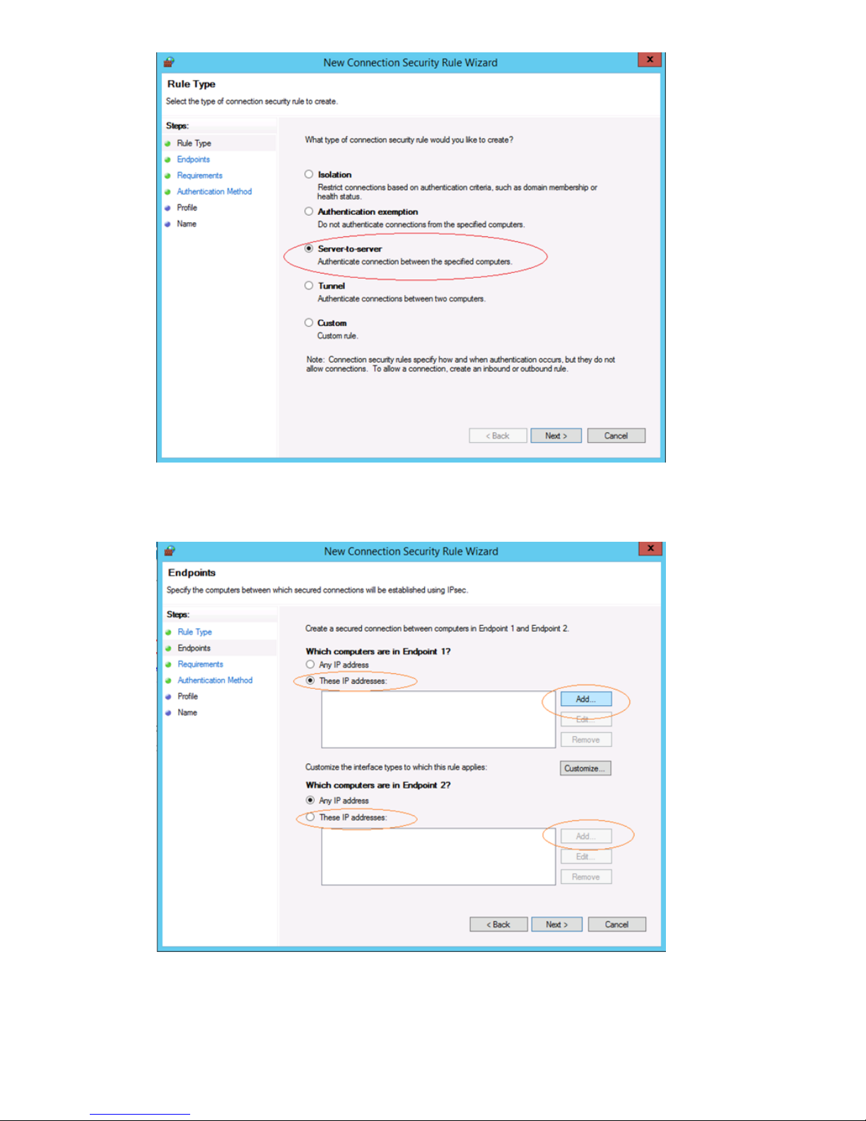
14. Click Next to move to Endpoints.
15. Under Which computers are in Endpoint 1, select These IP addresses and click Add.
16. Enter the IP address of the interface on the local machine (i.e. the Windows Server). An IP
range can also be entered if you have one.
86 Configuring backup servers to work with HP StoreOnce
Page 87

17. Under Which computers are in Endpoint 2, select These IP addresses and click Add.
18. Enter the IP address of the remote machine, which is the HP StoreOnce Backup system. Multiple
IP addresses on the HP StoreOnce Backup system can be configured here to connect to the
IP address specified for the media server. Click Next.
19. Select Require authentication for inbound and outbound connections.
20. Click Next to move to the Authentication Method step.
Configuring Data in Flight encryption on Windows media servers 87
Page 88

21. Select Advanced and click Customize.
22. In the Customize Advanced Authentication Methods window, click Add in the left hand side
under Fist authentication methods.
23. Select Preshared key.
24. Enter the same key that you provided when configuring the StoreOnce Backup system using
the StoreOnce CLI command, net add encryption (see To add Data in Flight
Encryption (page 49)). Click OK.
25. Click OK and click Next.
26. Select the network type to which this connection rule applies and click Next.
88 Configuring backup servers to work with HP StoreOnce
Page 89
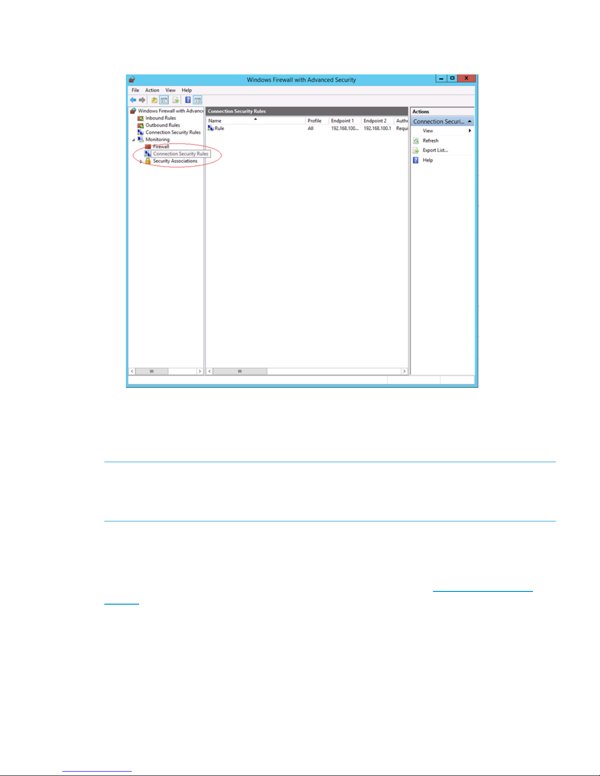
27. Provide a name for the connection and click Finish.
28. To view the status of the created connection rule, expand Monitoring>Security Associations.
Driver installation (optional, VTL only)
To create Virtual Tape Devices on the HP StoreOnce Backup system, two drivers are required—an
HP LTO Tape driver and a medium changer driver.
NOTE: Certain backup applications require their own drivers for both the tape device and medium
changer. For many applications these are installed automatically during the software installation
process. If the backup software is already installed, you may need to update manually the drivers
after installing the HP StoreOnce Backup system.
HP LTO Tape driver
The HP LTO Tape driver must be installed to allow your system to recognize the Ultrium tape devices
created by the HP StoreOnce Backup system.
Tape drivers can be installed from the HP website for driver updates at http://www.hp.com/
support. Search on the Product name and select Download Drivers and Software.
The tape drive is configurable as an LTO-2, LTO-3, LTO-4, LTO-5 or LTO-6 device. This is the default
behavior of the tape drive and there is no need and no way to change it on the HP StoreOnce
Backup system. It is important not to confuse emulation type with cartridge size. Emulation type is
independent from cartridge size. The HP StoreOnce Backup system allows you to pick a cartridge
size up to 3.2 TB.
Medium changer driver
No additional medium changer driver is required because Microsoft Windows provides a suitable
generic driver and all backup applications provide their own changer drivers.
Driver installation (optional, VTL only) 89
Page 90
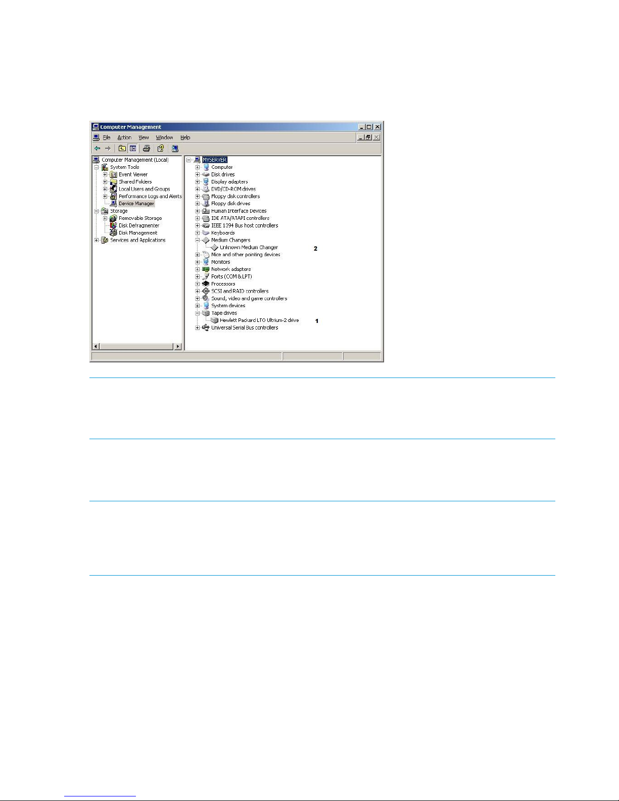
Device Manager
After installation, the HP StoreOnce Backup system does not appear as a device under My Computer
and it is not mapped to a drive letter. The host machine requires a backup application to back up
and restore data. However, if drivers are installed, the backup system can be viewed as a tape
drive (1) and medium changer (2) from the Device Manager.
NOTE: For a Fibre Channel Backup system, a new “unknown” device will be discovered in
Device Manager. This device is required only to ensure that a Fibre Channel target exists as LUN
0 in the SAN. No functionality is provided by this device and no driver is required. Note that this
device will be replaced by the Catalyst Over Fibre Channel initiator device if CoFC is configured.
iSCSI Initiator (optional, VTL only)
This section is not relevant if you are configuring only FC library devices, Catalyst stores or NAS
shares on your HP StoreOnce Backup system.
NOTE: FC products may be configured with a mixture of FC and iSCSI Virtual Tape Devices. If
you are configuring your HP StoreOnce Backup system to have iSCSI Virtual Tape Devices (for
hosts attached via the LAN ports), this section is relevant. However, if you are configuring it to
have only FC devices (attached via the FC ports), it is not necessary; you may use the StoreOnce
GUI or CLI to create FC library devices, see the HP StoreOnce Backup system user guide.
iSCSI is a protocol for sending SCSI commands via Ethernet. It defines how SCSI packets are
translated to Ethernet packets and connects to the required devices. An iSCSI initiator may be
hardware or software and should be running on each host. If the host does not have an iSCSI
initiator, it will not be able to connect to the library configured on the HP StoreOnce Backup system
and will not be able to perform backups.
For Linux and UNIX operating systems an iSCSI initiator is embedded in the operating system.
Please refer to the HP StoreOnce Backup system Linux and UNIX Configuration Guide for further
information. Make sure that you have downloaded the latest operating system patches before you
configure your system.
For Windows systems the Microsoft iSCSI initiator is required to connect to any Virtual Tape Libraries
created on the HP StoreOnce Backup system. The iSCSI initiator ships with later versions of Microsoft
Windows, but not with Windows 2003 or earlier. HP is not permitted to include the iSCSI initiator
on the CD. So, if required, it must be retrieved from the Microsoft website.
90 Configuring backup servers to work with HP StoreOnce
Page 91

NOTE: With some versions of Windows the iSCSI initiator service is not started by default. This
component must be configured manually by the user to run on startup. Do this through the Control
Panel.
Manual iSCSI initiator installation
1. On a machine that supports an external internet connection, go to the Microsoft website and
search on iSCSI initiator.
2. Select the result that takes you to the Download page and choose the download that is
appropriate for your host.
3. Download the iSCSI initiator and install it on the host, accepting all the default settings.
The iSCSI Initiator and Authentication
Authentication is not required for the HP StoreOnce Backup system, but it is supported for those
companies that have an IT policy that requires them to use authentication. If this is the case, you
will need to configure the necessary fields on the iSCSI Initiator and also ensure that the
corresponding information is supplied in the StoreOnce GUI. This enables the Initiator to log into
the target device on the HP StoreOnce Backup system and the target device to log into the Initiator.
The authentication method supported on StoreOnce products is CHAP. It relies on a "secret" known
only to the target and initiator. The size of the CHAP secret is between 12 and 16 characters, and
must be entered in exactly the same format in both the Web Management Interface and the iSCSI
initiator. An 'Authentication Failure' message will occur if the same 'secret' and 'user name'
information are not entered into the iSCSI Initiator screen and the Web Management Interface.
Further details on authentication and CHAP can be found within standard iSCSI protocol
documentation.
The recommended process if you wish to enable authentication is:
1. Create the devices on the StoreOnce GUI or CLI.
2. Set up the Targets in the iSCSI Initiator.
3. Connect to the devices using the CHAP user name and secret that you configured on the
Targets tab.
The Microsoft iSCSI Initiator
The Microsoft iSCSI initiator contains a number of tabs. This section describes the information that
must be provided in order to connect the host to a device on the HP StoreOnce Backup system. It
does not provide a comprehensive description of all the tabs; please download the “User Guide”
from the Microsoft website for more information.
NOTE: The screenshots below may not be correct for your operating system. They are taken from
an iSCSI Initiator running on a Windows 7 operating system.
iSCSI Initiator (optional, VTL only) 91
Page 92
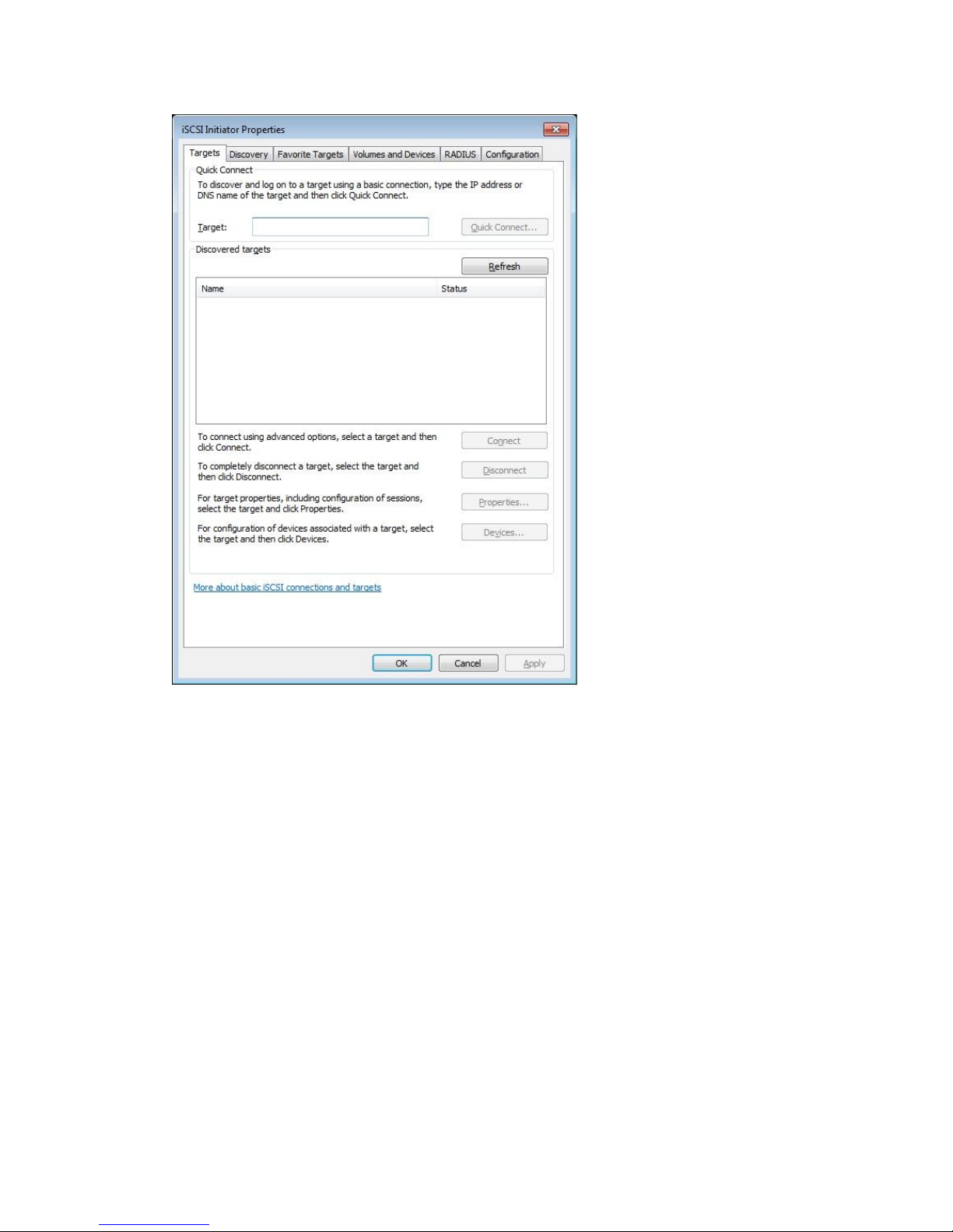
1. The Targets tab is the default tab when you run the iSCSI Initiator for the first time. At this point
no targets have been discovered.
2. Select the Discovery tab. At this point there are no target portals.
92 Configuring backup servers to work with HP StoreOnce
Page 93

3. Click Discover Portal... You must enter the IP address or fully qualified domain name of the
HP StoreOnce Backup system (for example, mystoreonce.mydomain.com) to add it as a target
portal for the host on the Discovery tab. Do not change the Port; it should be 3260.
4. Click on OK to add the target portal to the Discovery page. You may need to click Refresh.
iSCSI Initiator (optional, VTL only) 93
Page 94
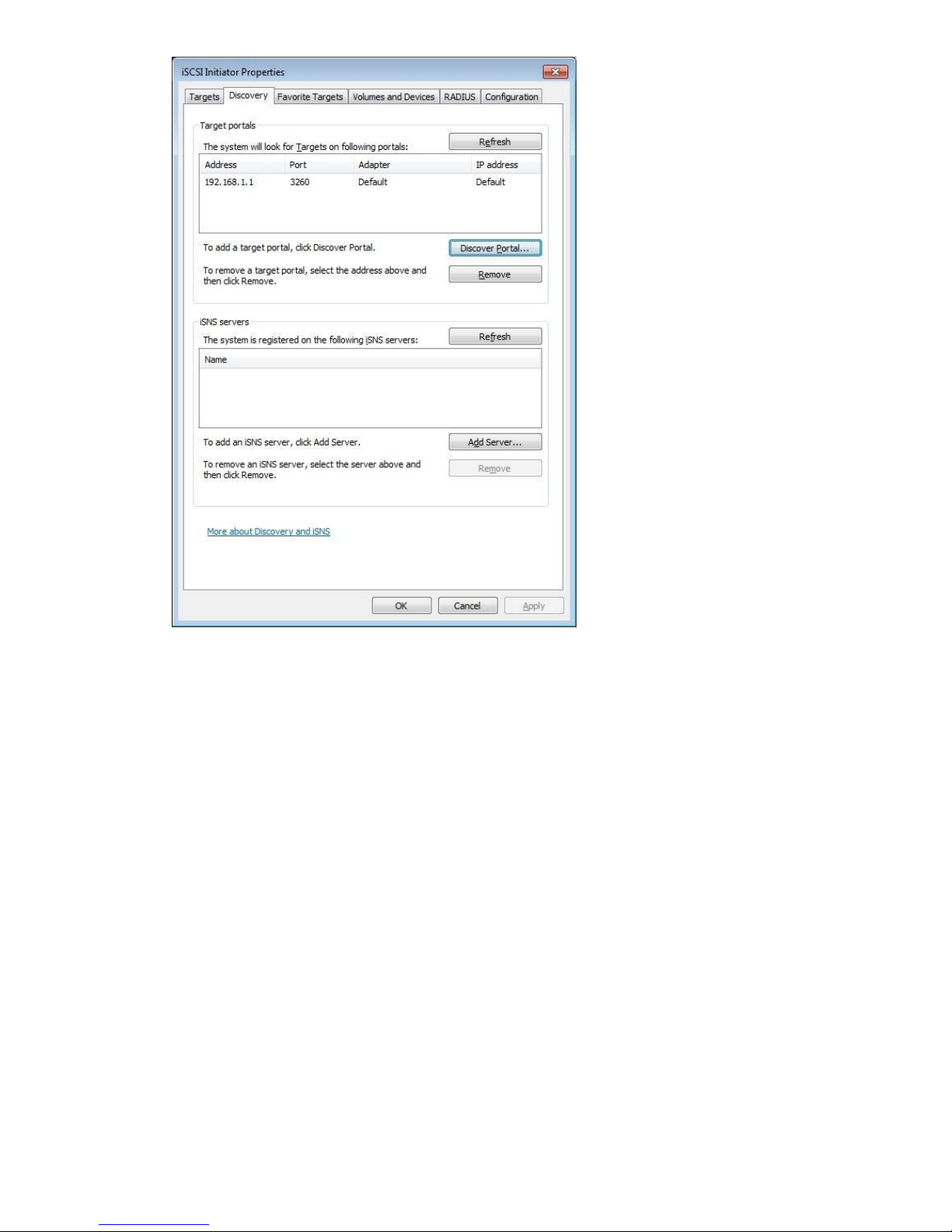
5. When you run the iSCSI Initiator manually, new devices have a status of Inactive on the Targets
tab. You must log on to the appropriate targets for your host. Remember that each library has
at least two devices and you must log onto each one separately. If the emulation type you
have selected allows more drives, there will be a target device for each drive.
94 Configuring backup servers to work with HP StoreOnce
Page 95

6. Select the first target in the list and click on Connect. We recommend that you enable the first
checkbox to make the connection a Favorite target, so that you do not have to manually
connect to it in the future.
NOTE: If you wish to use CHAP authentication, click Advanced... before you click OK. See
separate section below for more details about CHAP authentication.
7. Repeat until all required targets have been added.
8. Click OK. The targets are now showing as Connected.
iSCSI Initiator (optional, VTL only) 95
Page 96

96 Configuring backup servers to work with HP StoreOnce
Page 97
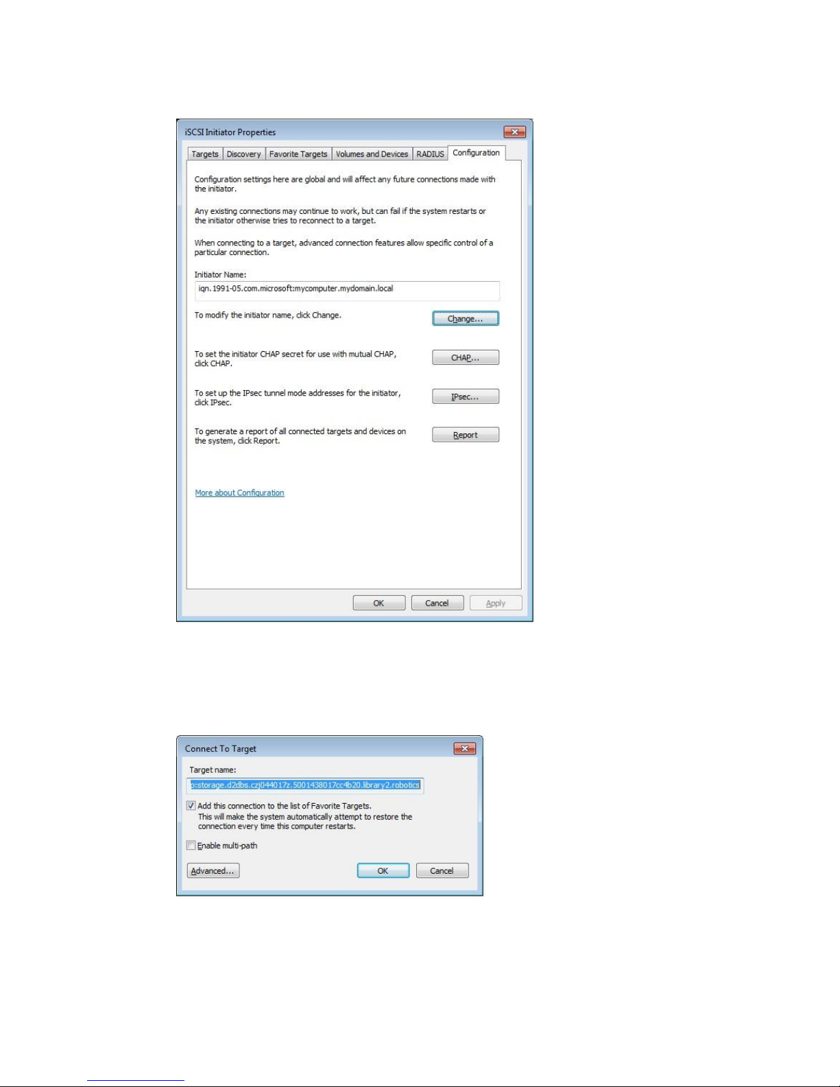
9. Look at the Configuration tab. When you use the StoreOnce GUI or CLI to create library
devices, you must provide the iSCSI Initiator Name, which you will find on this tab. (You also
use this tab to set up the CHAP secret if you have enabled mutual authentication.)
CHAP Authentication
1. If you wish to use CHAP authentication , click Advanced... on the Connect to Target dialog.
(IPSec Tunnel Mode is not supported.)
2. Check Enable CHAP logon and enter the secret in the Target Secret box. The CHAP secret
may be between 12 and 16 alphanumeric characters. It should be the same string as you
enter for the Initiator CHAP Secret and the Name is used for Initiator User Name on the
StoreOnce Management Interface. See the HP StoreOnce Backup system user guide for more
information.
iSCSI Initiator (optional, VTL only) 97
Page 98

3. If you want to use mutual authentication, which means that the target must also log on to the
Initiator, make sure that the Perform mutual authentication box is checked. The secret for
mutual authentication is set on the Configuration tab. You must also provide the Target User
Name and Secret when you configure the device in the StoreOnce Management Console.
Favorite Targets tab
The Favorite Targets tab shows the targets that have been configured to restore automatically on
reboot. During initial configuration, it is for information only. However, if you want to stop the host
automatically connecting to a device, you must select the device on this tab and Remove it. (To
disconnect the device without rebooting, go back to the Targets tab, select the device, and click
Disconnect.)
98 Configuring backup servers to work with HP StoreOnce
Page 99

iSCSI Initiator (optional, VTL only) 99
Page 100

11 Understanding LEDs
If an LED indicates an error condition, HP recommends reviewing the StoreOnce Event log for more
information.
For hardware-related errors the Hardware page of the StoreOnce GUI provides valuable information.
In this chapter:
• Front view of the HP StoreOnce 4700 Backup system (page 101)
• Capacity upgrade kit LEDs (page 102)
• Front view of the HP StoreOnce 4500 Backup system (page 103)
• Front view of the HP StoreOnce 2700 Backup system (page 105)
• Front view of the HP StoreOnce 2900 Backup system (page 104)
• Drive LEDs (page 106)
• 1 Gbit ethernet port LEDs (page 107)
• 10 Gbit ethernet port LEDs (page 107)
• Fibre Channel card LEDs (page 108)
NOTE: All diagrams show the unit with the cover plate removed.
100 Understanding LEDs
 Loading...