

Page 1

HP SmartStream 3D Build Manager
User Guide
Page 2

© Copyright 2018 HP Development Company,
L.P.
Edition 1
Legal notices
The information contained herein is subject to
change without notice.
Trademarks
Intel® and Intel Core™ are trademarks of Intel
Corporation in the U.S. and other countries.
The only warranties for HP products and
services are set forth in the express warranty
statement accompanying such products and
services. Nothing herein should be construed as
constituting an additional warranty. HP shall not
be liable for technical or editorial errors or
omissions contained herein.
Microsoft® and Windows® are U.S. registered
trademarks of Microsoft Corporation.
Page 3

Table of contents
1 Introduction ............................................................................................................................................................................................... 1
Interface overview .................................................................................................................................................................... 1
2 Preferences ................................................................................................................................................................................................ 7
About preferences .................................................................................................................................................................... 7
Set preferences ......................................................................................................................................................................... 8
Connect to a Command Center printer ................................................................................................................................. 8
3 Adding parts ............................................................................................................................................................................................ 10
Add parts ................................................................................................................................................................................. 10
To ll the build volume .......................................................................................................................................................... 10
Automatic part arrangement ............................................................................................................................................... 10
Automatic part and build checking ...................................................................................................................................... 11
About part reports ................................................................................................................................................................. 12
Create a part report ............................................................................................................................................................... 12
4 Working with parts ................................................................................................................................................................................. 13
Select parts ............................................................................................................................................................................. 13
Adjust the position of a part ................................................................................................................................................. 13
Resize (scale) a part ............................................................................................................................................................... 13
Change the view ..................................................................................................................................................................... 14
Hollow a part ........................................................................................................................................................................... 14
Cut away a view ...................................................................................................................................................................... 15
Change the color view ........................................................................................................................................................... 15
Changing colors ...................................................................................................................................................................... 15
Cage parts ............................................................................................................................................................................... 16
5 Printing parts ........................................................................................................................................................................................... 18
Send a job to a printer ........................................................................................................................................................... 18
About job reports ................................................................................................................................................................... 19
6 Working with les ................................................................................................................................................................................... 20
Save a job ................................................................................................................................................................................ 20
ENWW iii
Page 4

7 When you need help .............................................................................................................................................................................. 21
Appendix A Software requirements ........................................................................................................................................................ 22
Appendix B Keyboard shortcuts .............................................................................................................................................................. 23
Index ............................................................................................................................................................................................................. 24
iv ENWW
Page 5
1 Introduction
Use the powerful 3D print-preparation capabilities of HP SmartStream 3D Build Manager to help make all of your
3D printing jobs successful:
1. Add parts to begin preparing the print job.
2. Rotate, size, and position parts on the bed.
3. Automatically locate and x 3D geometry errors, adjust part colors, and hollow parts to use less material..
4. Send a printer-ready le to a connected 3D printer or save the printable le.
This preparation can save time and money by helping you to avoid the frustration of trial-and-error printing.
Interface overview
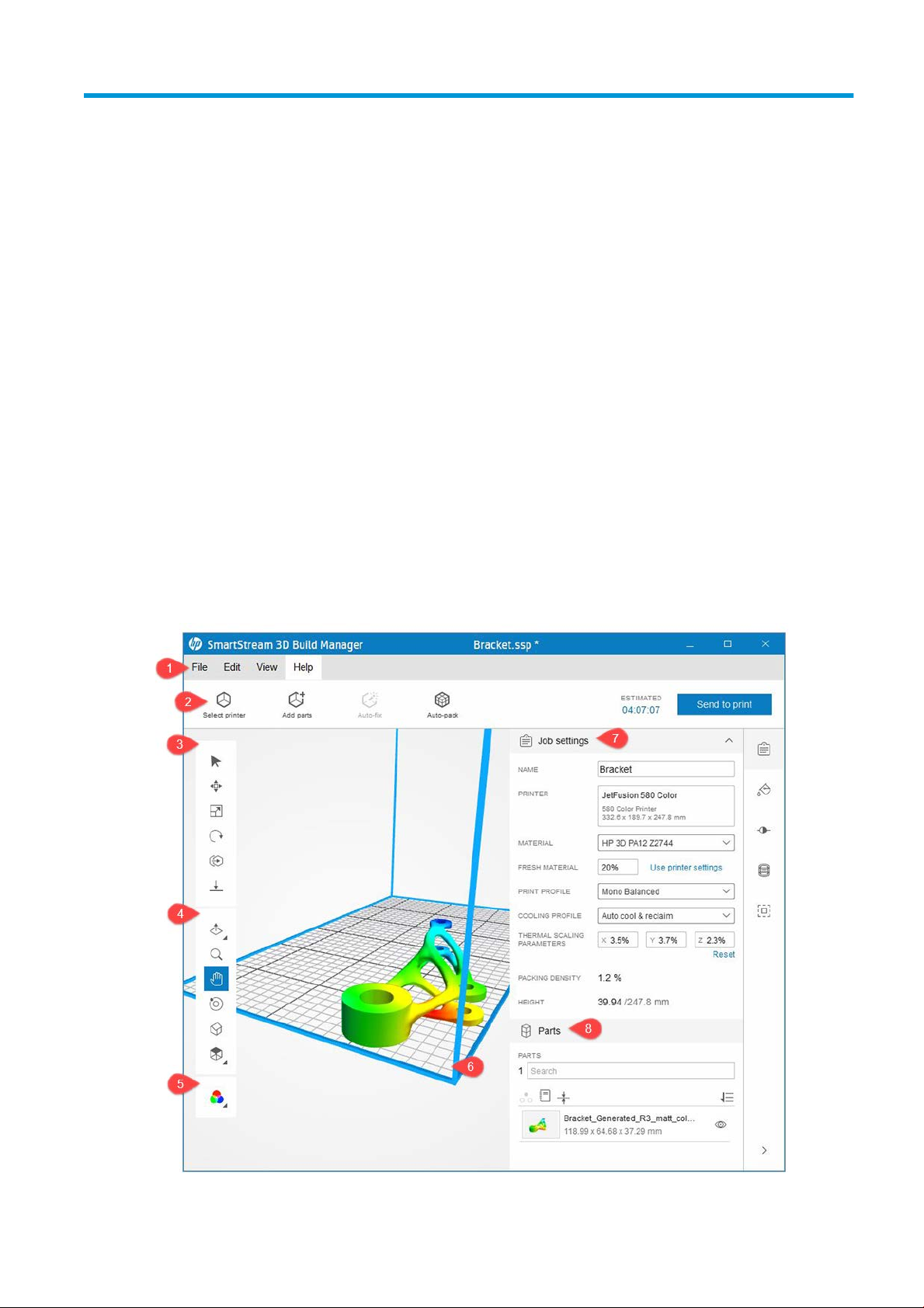
Here is a snapshot of the application with a model ready to be printed.
ENWW Interface overview 1
Page 6
Toolbars
1. Menu bar: Provides le management tools, editing tools and preferences, viewing controls, and learning
content.
2. Action bar: Provides common tasks for preparing jobs to print and estimating printing times.
3. Transform toolbar: Provides tools for manipulating parts in the build volume.
4. Viewing toolbar: Provides tools for manipulating the view and navigating within the viewport.
5. Color view mode: Oers a choice between geometry view, color view, and print view.
6. Viewport: The work area that includes the build volume. The build volume, typically indicated by blue
boundary lines, is the printable volume.
7. Content panel: Contains ve tabs along the right-hand side the provide access to groups of related tools.
8. Parts panel: Provides a list of all the items in the job, including actions to manipulate the list and interact
with the parts and cages.
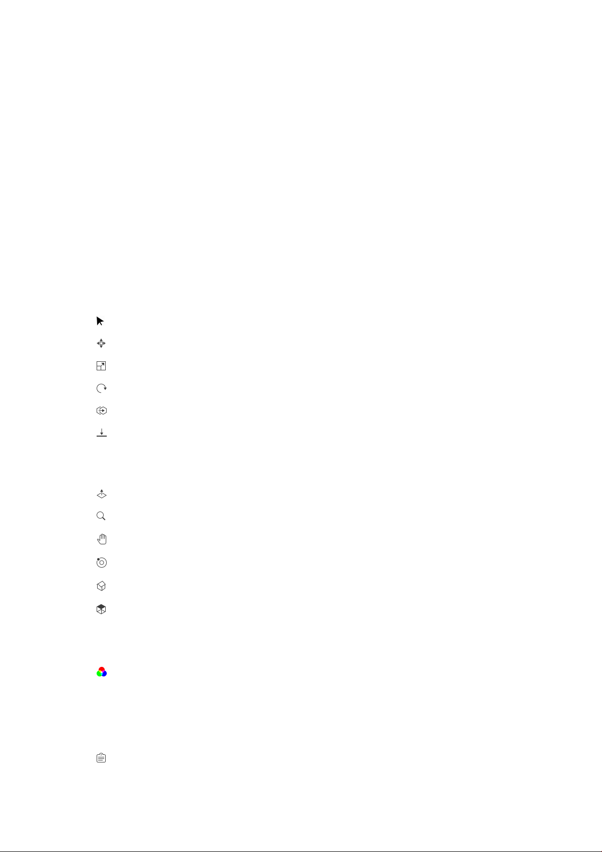
Transform toolbar
Select
Move
Scale
Rotate
Duplicate
Move to bed
Viewing toolbar
Cutaway
Zoom
Pan
Orbit
Home view
Orthographic view
Color view toolbar
Color view
Content panel
Content panel tabs
Job settings
2 Chapter 1 Introduction ENWW
Page 7
Content panel tabs (continued)
Part color
Color adjustment
Hollow
Caging
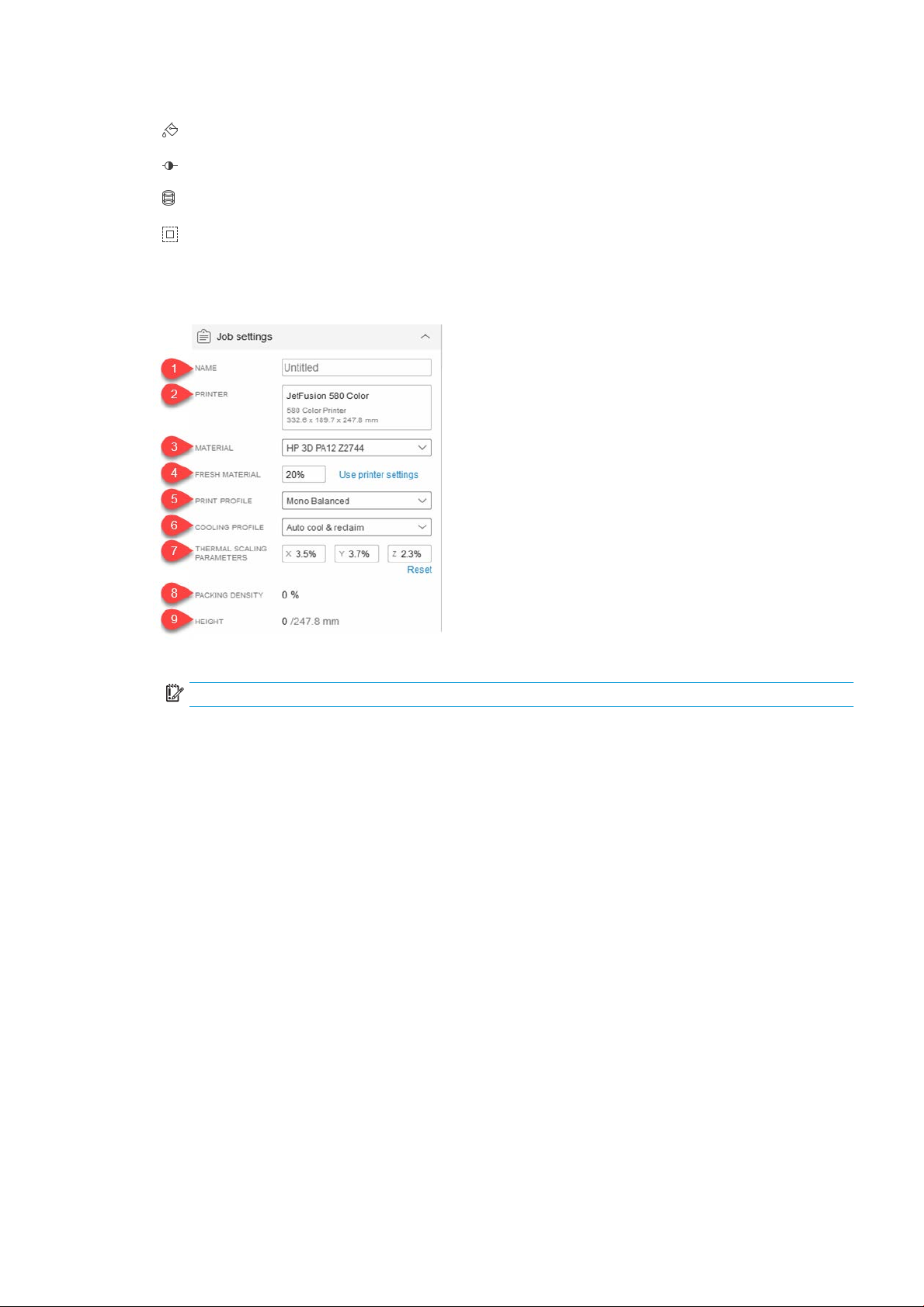
The
job settings tab provides details about the job and the printer settings being used.
1. JOB NAME: The name of the job.
IMPORTANT: Changing the job name here also changes the name of the le.
2. PRINTER: Identies
3. MATERIAL: Some printers enable you to select a material.
4. FRESH MATERIAL: Some printers used recycled material. This setting enables you to select the amount of
ne
w material to be used.
5. PRINT PROFILE: Identies the selected group of print settings.
6. COOLING PROFILE: Select a preset to determine how long the printer should wait to cool the parts.
7. THERMAL SCALING PARAMETERS: Compensation factor for distortion based on the print volume. The
c
orrect setting depends on the material. Change here if results are not as expected. Parts are scaled to
accommodate the distortion.
8. PACKING DENSITY: The occupied proportion of the build volume up to the height of the highest positioned
p
art.
9. HEIGHT: The height of all parts in the job. The maximum build volume height is also indicated. The build
height upda
The part color tab provides tools to sample the existing part colors, and to change them using existing and
custom color swatches.
the selected printer.
tes as parts are added, moved, and removed.
ENWW Interface overview 3
Page 8
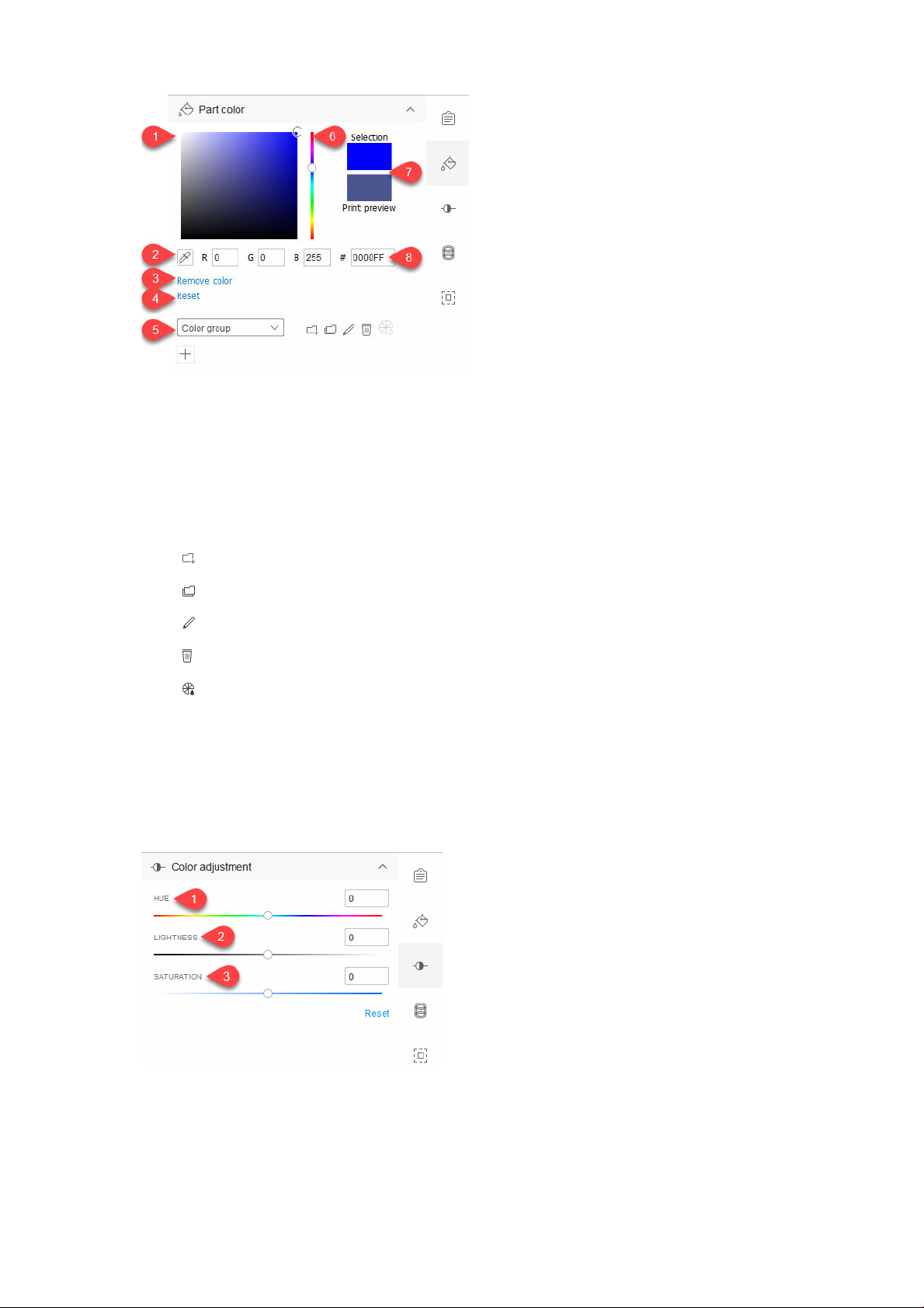
1. Saturation/lightness area: Drag to adjust the color of the selected part.
2. Eyedropper: Click the tool and select a color in the build volume to apply it to the selected part.
3. Remove color: Removes all color information from the selected part.
4. Reset: Returns the part to its initial color.
5. Color swatches: Select from default color groups to display the colors in the swatch area.
Add a new color group
Duplicate an existing color group
Edit an existing color group
Delete the selected color group
Generate a color proof
6. Hue: Drag the slider up or down to adjust the color of the selected part.
7. Color preview area: Displays the adjusted color of the selected part and provides a print preview.
8. RGB/Hex value: Enter a color value to apply it to the selected part.
The color adjustment tab provides tools to adjust the hue, saturation, and value of the selected part.
1. HUE: Drag the slider left or right to adjust the hue of the selected part.
2. LIGHTNESS: Drag the slider left or right to adjust the lightness of the selected part. Use Reset to return to
the default values for the selected object.
3. SATURATION: Drag the slider left or right to adjust the saturation of the selected part.
4 Chapter 1 Introduction ENWW
Page 9
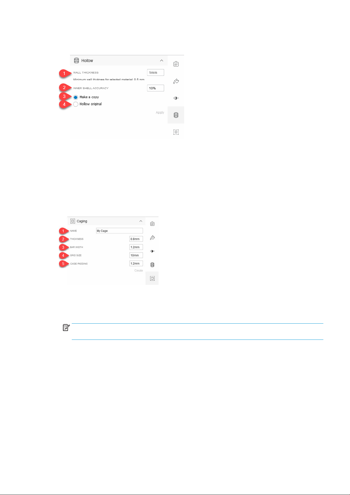
The hollow tab enables you to hollow a solid part by choosing the resulting wall thickness after the hollowing is
complete. Hollowing a part can reduce the amount of material used and increase printing speed.
1. WALL THICKNESS: Set the new wall thickness for the hollowed part.
2. INNER SHELL ACCURACY: Adjust the accuracy of the hollowed wall thickness setting. Increasing accuracy
may slow the creation of the inner shell. The more accurate, the longer it takes to create.
3. Make a copy: Apply the hollowing settings to a copy of the original part.
4. Hollow original: Apply the hollowing settings to the original part.
The caging tab enables you to create and modify a container, or cage, that enables you to group and print related
parts.
1. NAME: Name the cage to be created around the selected parts.
2. THICKNESS: Adjust the cage bar thickness.
3. BAR WIDTH: Adjust the cage bar width. The value must be greater than or equal to the thickness value.
NOTE: Increasing the thickness and bar width values can cause other cage-related values to be adjusted
automatically.
4. GRID SIZE: Adjust the size of the cage grid. The value must be at least double the bar width value.
5. CAGE PADDING: Adjust the space between the parts and the cage. The value must be at least as much as
the bar width value.
ENWW Interface overview 5
Page 10
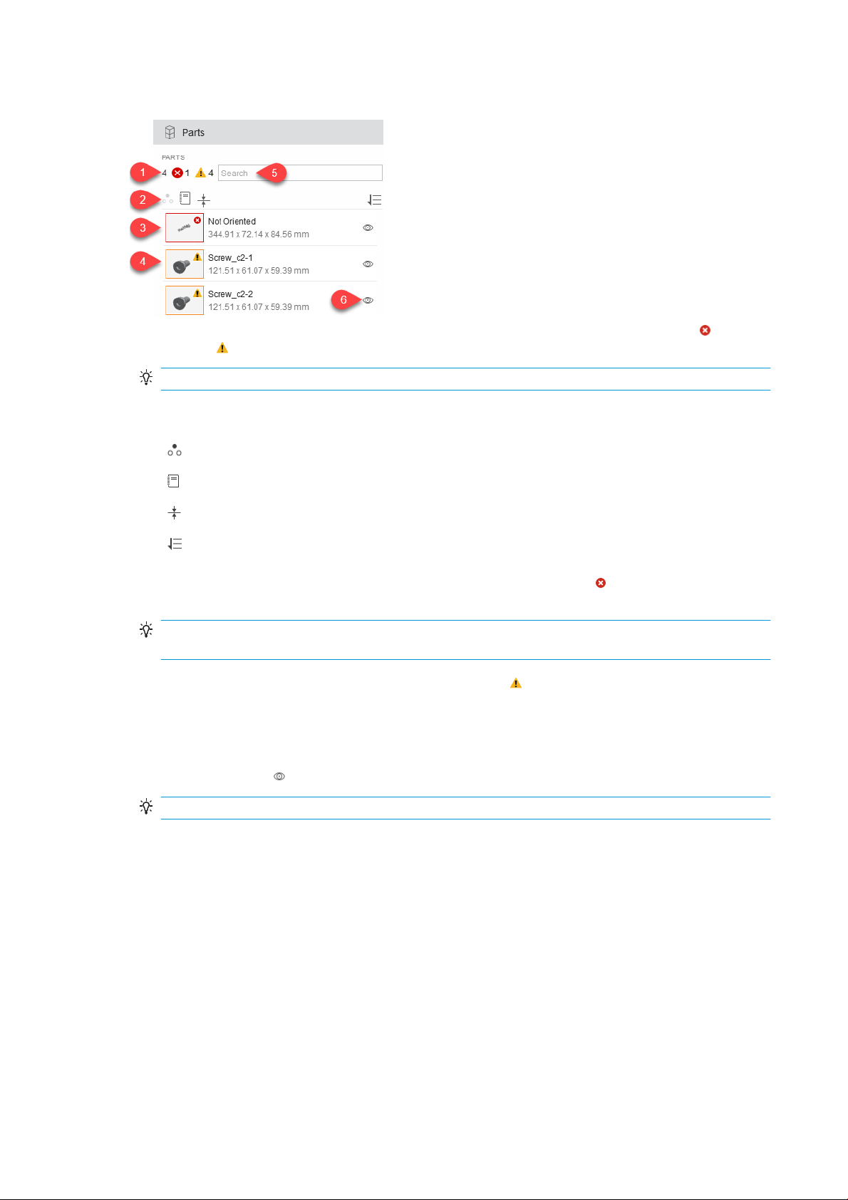
Parts panel
1. Total number of parts in the build volume and viewport and number of added parts with errors and
2. Parts panel tools.
warnings . Use the color view toolbar to switch to geometry view to see the errors.
TIP: Click the number to select parts with issues.
Isolate
Part report
Analyze wall thickness
Sort parts list
3. Part with an error. The parts list shows a thumbnail image with an error icon indicating one or more
issues with that part. Each part also shows the part name and dimension information.
TIP: If the listed part shows an error, double-click the listed part for more details. You can auto-x the
issue, and/or create a part report.
4. Part with a warning. The thumbnail image has a warning icon indicating that the part is out of bounds.
Out-of-bounds parts are not included in the number of parts with errors.
5. Search for parts in the list. As you type, the parts list is ltered to show only those parts including those
characters. Clear the search term to see the entire parts list again.
6. The hide/show tool enables you to control the visibility of each part in the build volume.
TIP: After a part has been hidden, right-click and choose Show all.
6 Chapter 1 Introduction ENWW
Page 11

2 Preferences
About preferences
Preferences control default behaviors in the application. Once preferences are saved, they are retained and used
each time you start the application. The Preferences dialog box has two tabs: General and Command Center
connection.
General
The General tab provides settings for controlling the application.
● Global settings
– Language: Select the desired language for the application and restart the application.
– Units: Select the desired units of measurement: millimeters, centimeters, or inches.
– Reset all messages and warnings: If not enabled, enable this setting to display the messages again.
● Parts
– On add/duplicate parts, auto-pack: Select the default behavior for how you want imported or
duplicated parts to be managed in the viewport.
○ 2D: Automatically arranges all parts horizontally on the bed in the build volume. If there is no
room, parts are placed outside the build volume in the viewport.
○ 3D: Automatically arranges all parts horizontally and vertically within the build volume. If there is
no room, parts are placed outside the build volume in the viewport.
○ None: Keeps the part arrangement as saved in the imported design le. This option can cause
part collisions, including complete overlaps.
○ Ask every time: When parts are imported or duplicated, you are prompted to select an auto-
packing option.
– Auto-pack tolerance: Adjust part spacing precision. Lowering the tolerance increases accuracy but
decreases performance. The default value is 5 mm and the minimum value is 1 mm.
– Show warning for out of bounds: Select whether you want out-of-bounds warnings to be shown.
– Remind to check minimum wall thickness: When enabled, after clicking Send to print, you are
prompted to check parts for wall thickness issues before the job is actually sent.
IMPORTANT: If a wall thickness error is detected, each area of a part that has an insuicient wall
thickness for the selected printer is colored red. The application cannot x parts with wall thickness
errors. You can only remove them from the build volume. Wall thickness errors do not prevent you
from printing.
– Wall thickness surface coverage: Denes the allowable tolerance for each part’s wall thickness that
can be thinner than the printer-dened capability without invoking a warning. For example, by default
ENWW About preferences 7
Page 12
the surface coverage value is set at 5%. If less than 5% of a part is too thin to print, a warning will not
be shown. If more than 5% of a part is too thin to print, a warning will be shown
– Separate 3MF components on import: Choose to bring in as a single part or multiple parts to interact
with in the build volume.
● File locations
– Path to save temporary les needed to send a print job: Select the location to save temporary les
created while sending the job to the printer.
– Path to save reports: Select the location to save reports.
TIP: To access that location, choose File > Reports.
The application creates two dierent reports, part reports and job reports, to help you track issues
with parts and to document the printing process. Reports are PDF les. The report names are based
on the job name entered in the job settings tab.
NOTE: Changing the job name also changes the name of the le.
The report names also include a date and time stamp, indicating exactly when the report le was
generated. When you need to share reports, print or email the PDF les.
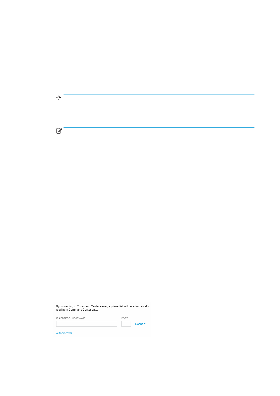
Command Center connection
The Command Center connection tab enables you to use an IP address and port number to connect to the
Command Center to use the listed printers.
Set preferences
1. Open the Preferences dialog box using one of these methods:
● Click Edit > Preferences.
● Press Ctrl+K.
2. Make the changes you want to make on the appropriate tabs.
3. Click Save.
When you rst start HP SmartStream 3D Build Manager, you will need to connect to a Command Center printer.
Connect to a Command Center printer
1. On the menu bar, click Edit > Preferences.
2. In the Preferences dialog box, on the Command Center connection tab, click Autodiscover or enter an IP
address or hostname, and a port if applicable.
3. Click Connect.
4. Close the Preferences dialog box.
8 Chapter 2 Preferences ENWW
Page 13

5. Open the Select printer dialog box using one of these methods:
● On the action bar, click Select printer.
● In the job settings tab, click the currently selected printer.
6. From the list of printers, click the printer you want to use.
The selected printer is shown in the job settings tab.
ENWW Connect to a Command Center printer 9
Page 14

3 Adding parts
Add parts
IMPORTANT: The application supports 3MF, OBJ, STL, and WML (VRML) les.
1. Open the Open dialog box using one of these methods:
● On the action bar, click Add parts.
● Click File > Add parts.
● Press Ctrl+I.
2. Select the part les that you want to add.
3. Click Open. The parts are added, shown in the viewport, and listed in the part browser panel.
NOTE: Depending on the preferences you have chosen, added parts may be auto-packed for you.
TIP: If you make a mistake, choose Edit > Undo (Ctrl+Z), Edit > Redo (Ctrl+Shift+Z), or just start again.
Choose File > New (Ctrl+N) to discard all changes.
4. If necessary, size the parts to t in the build volume using one of these methods:
● Click Scale to t so that parts will automatically be sized to t, and click OK.
● Select the unit used to design the part originally, and click OK.
To ll the build volume
If you want to include as many of the same part as possible in the build volume, to make the most of the print
job, add one part and click Edit > Fill build volume.
IMPORTANT: You must have only one part selected.
Automatic part arrangement
You can have the application automatically pack the parts within the build volume for you at any time. If parts are
outside the build volume (shown as yellow), using Auto-pack arranges as many parts as possible horizontally
and vertically within the build volume for the most eicient printing of the job. The approximate part spacing is
added to the minimum spacing value required by the selected printer, creating the total space between parts. A
zero value means the parts will be printed as closely together as possible. If not all the parts will t, they are
aligned in the viewport outside the build volume. If all parts t, the adjusting the spacing value may enable you to
t more parts into the build volume.
10 Chapter 3 Adding parts ENWW
Page 15

1. On the action card, click Auto-pack.
2. You have the opportunity to modify the Approximate part spacing.
3. Click Auto-pack.
Automatic part and build checking
IMPORTANT: Use the color view toolbar to switch to geometry view to see the errors in the viewport.
When parts are added, the application automatically checks that the parts satisfy various conditions:
● In bounds: Are the parts positioned within the build volume so that they can be printed?
● Closed: Do the parts have holes?
● Correctly oriented: Are the parts positioned so they can be printed properly?
● Topologically valid: Are the parts printable?
Parts beyond the boundaries of the build volume are considered out of bounds. Out-of-bounds parts can usually
be xed by clicking Auto-pack, or by manually moving the out-of-bounds part into the build volume. Parts
with holes, troublesome orientations, and topologically invalid parts can usually be xed by clicking .
IMPORTANT: Until these issues have been addressed, you will be prevented from printing.
The application uses colors to indicate the status of parts:
● Gray: The part is unselected. No issues detected.
● Blue: The part is either being pointed at with the mouse or is selected. No issues detected.
● Red: The part either has a repairable issue such as a hole (autox) or an unrepairable issue (needs to be
xed in some other application or removed from the build volume). If a part is not repaired, printing is
prevented. Red can also indicate areas of a part that have insuicient wall thickness for the selected printer.
When sending to a printer, a warning is issued, but printing is not prevented.
● Yellow: The part is not within the boundaries of the build volume (out of bounds), which prevents printing.
Optionally, the application can analyze parts for thin walls that may cause issues when printed. Acceptable wall
thickness depends on the type of printer (see the printer’s user guide). To check for wall thickness issues, click
in the parts panel. If you do not check parts for wall thickness issues before you click Send to print, you will be
reminded to do so then.
IMPORTANT: If a wall thickness error is detected, each area of the part that has an insuicient wall thickness for
the selected printer is colored red. The application cannot x parts with wall thickness errors. You can only
remove them from the build volume. Wall thickness errors do not prevent you from printing.
ENWW Automatic part and build checking 11
Page 16

About part reports
Part reports can be run at any time for selected parts. When no parts are selected, the report includes all parts in
the viewport. Once created, a part report begins with a section listing parts with issues. If no parts have issues,
the sort order set in the parts panel determines how parts are listed in the part report. For each part in the
report, the part name, thumbnail image, and dimensions are provided. If a part has no errors, next to each part
are some blank lines you can use to take notes. If there are errors, the error type is identied.
All reports are PDF les stored in the location dened in Preferences. You can browse to that location to review a
report at any time.
Create a part report
You can create a part report in any of these ways:
● Right-click a part or selection and click Part report.
● In the parts panel, click .
● In a part’s error dialog box, click Part report.
12 Chapter 3 Adding parts ENWW
Page 17

4 Working with parts
Select parts
Once parts have been added to the viewport, before you can manipulate them, you have to select them.
You can select parts in any of these ways:
● On the Transform toolbar, click and then click the part you want to select.
TIP: To select multiple parts, draw a selection box around the parts.
● Click a part in the parts list.
● Choose Edit > Select all (Ctrl+A) to select all parts in the viewport.
● Choose Edit > Select all with errors (Ctrl+E) to select all parts that have errors.
● Choose Edit > Select all out of bounds (Ctrl+B) to select all parts outside the build volume.
TIP: With a part selected, right-click it and choose from a variety of actions, such as Isolate (hides all unselected
parts), Hide selection, Duplicate (the Edit menu also has options for duplicating parts), and Delete.
Adjust the position of a part
1. Select the part you want to position.
2. On the Transform toolbar, click . The Move tools are shown around the part.
3. Use the Move tools to position the part or enter X, Y, or Z values for more precise location.
TIP: Drag the up arrow to show the Z value input box.
4. Also on the Transform toolbar, click . The Rotate tools are shown around the part.
5. Use the Rotate tools to position the part or enter rotation angle values for more precise location.
TIP: You can also use to position a part on the bed in the build volume.
Resize (scale) a part
1. Select the part you want to resize.
2. On the Transform toolbar, click . The Scale tools are shown around the part.
3. You can resize the part in any of these ways:
ENWW Select parts 13
Page 18

● Use the scale handles.
● Enter individual X, Y, or Z values.
● Enter a percentage value.
Change the view
You can change the view in any of these ways:
●
To pan the view:
● Press and hold the mouse wheel while dragging the mouse to view the desired position.
● On the Viewing toolbar, click . Then click and drag the view to the desired position.
● To zoom the view:
● Roll the mouse wheel forward to zoom in and backward to zoom out.
● On the Viewing toolbar, click , click the view, and move the mouse forward to zoom in and backward
to zoom out.
● To orbit the view:
● Right-click while dragging the mouse to view the desired position.
● On the Viewing toolbar, click . Then click and drag the view to the desired position
● To select a preset view:
TIP: Selecting a preset view leaves the current tool selected.
● From the View menu, choose Fit all (A), Fit selection (F), Home (H), Front (Ctrl+1), Back (Ctrl+2), Left
● On the Viewing toolbar, click .
● On the Viewing toolbar, click and select the desired position: (top), (right), (front),
Hollow a part
1. Select the part or parts to be hollowed. If no parts are selected, all parts in the build volume will be
hollowed.
2. In the content panel, click .
3. Set the wall thickness after hollowing. You cannot make the wall thickness thinner than the material and
printer settings allow.
4. Choose to hollow a copy of the selection or the original selection itself.
(Ctrl+3), Right (Ctrl+4), Top (Ctrl+5), or Bottom (Ctrl+6).
(bottom), (left), or (back).
5. Click Apply.
6. Once hollowed, you can use to see the hollowed part..
14 Chapter 4 Working with parts ENWW
Page 19

Cut away a view
Cut away the build volume to look inside parts and to assess possible part conicts and spacing. Using this view
does not aect the printability of the parts, it aects only your view of them. If a part is completely cut away and
hidden in the build volume, you can still select it in the parts list.
1. On the Viewing toolbar, click and select the desired position: (cut Z axis), (cut Y axis), or (cut X
axis).
TIP: Place the Cutaway dialog box where needed.
2. Optionally, use any of the preset views (home or view ) or mouse shortcuts to pan , zoom , or
orbit
3. In the Cutaway dialog box, use the position tools to move the cutting plane to the desired location.
TIP: In the build volume, you can also click to drag the arrow and move the cutting plane to the desired
location.
4. Optionally, click Invert to ip the cutting plane. Click Section to show a at surface, or cap, across the
sectioned parts. Use the slider or entry box to position the cutting plane accurately.
5. Click again to turn o the cutaway view.
for a better view of the cut.
Change the color view
All parts in the viewport are aected by your color view selection.
On the color view toolbar, click one of these options.
Geometry view: Shows parts in a basic color scheme. Use this mode to view part errors and
warnings.
Color view: Shows parts in their original colors and textures as designed.
Print view: Simulates how the parts will look when printed based on the selected material, printer,
and printer settings.
Changing colors
The application oers several ways to manage part colors using the tab (change color properties for all parts
at once) and the tab (change color properties for selected parts) on the content panel. On the tab, some
default color groups are available from the drop-down list. These are locked and cannot be modied, but they
can be duplicated. You can also create your own color groups.
Create a color group
1. In the content panel, on the tab, click .
2. Enter a name for the color group.
3. Select a color using the eyedropper, RGB or hexadecimal values, or the saturation/lightness area.
4. Below the color group name, click to include the selected color in your color group.
TIP: You can add 13 color swatches. To remove one, right-click the color swatch and select Delete.
ENWW Cut away a view 15
Page 20

Modify a color group
1. In the content panel, click the tab.
2. Select the color group to be modied and use one of these methods:
● Click to create a copy.
● Click to change the name.
● Click to remove it.
Create a color proof
When you have selected a color printer and a color group, the application enables you to load and print a sample
part you can use to test the selected printer’s color settings.
1. In the content panel, click the tab.
2. Click . The new color proof part is added to the build volume ready to be printed.
Change a part color
1. On the color view toolbar, click to view the part color changes.
2. Select a part and use one of these methods:
● Click to choose a new color in the viewport.
● Click a color swatch in a color group.
● Enter RGB values or a hexadecimal value.
The selected color is applied immediately in the viewport.
TIP: With the part still selected, click Remove color or Reset to correct any unwanted changes.
Cage parts
Caging enables you to create a physical container, or cage, around selected parts to group and print them. Use
caging to separate multiple outputs in one print job.
1. Select the part or parts to be caged.
2. In the content panel, click the tab.
3. Name the cage.
4. Optional: Modify the cage properties or padding around parts within the cage.
5. Click Create.
The cage is listed in the parts panel.
In the parts list, each caged part shows a cage icon.
16 Chapter 4 Working with parts ENWW
Page 21

TIP: You can remove a part from a cage by either right-clicking a part in a cage or in the parts list and selecting
Unlink from cage.
TIP: You can delete a cage by right-clicking it in the parts list and selecting Delete. Only the cage is deleted. The
parts remain.
TIP: Recommended caging parameters are:
●
Thickness: 0.8 mm
●
Bar width: 1.2 mm
Grid size: 10 mm
●
●
Cage padding: 1.2 mm
ENWW Cage parts 17
Page 22

5 Printing parts
Send a job to a printer
1. You can start printing in any of these ways:
● On the action bar, click Send to print.
● Click File
● Press
2. If prompted to analyze wall thickness:
● Click
● Alternatively, click Continue to ignore the prompt and send the job to the printer regardless.
. The job is sent directly to the printer. Once printing has started, you can monitor the job from the printer’s
3
front panel using the Command Center.
NOTE: During slicing and le
cancel it.
> Send to print.
Ctrl+P.
Analyze. If any wall thickness errors are found, click Remove parts and start printing again.
creation, you can cancel the job. Once the job is being sent, you can no longer
. Optional: Once the job has been sent to the printer, click View job report to see the PDF summary of the
4
parts included in the print job.
18 Chapter 5 Printing parts ENWW
Page 23

TIP: To view reports later, click File > Reports.
5. Click Done.
About job reports
Job reports are run when you click Send to print. The sort order set in the parts panel determines how parts are
listed in the job report. For each part in the report, the part name, thumbnail image, and dimensions are
provided. Next to each part are some blank lines you can use to take notes.
NOTE: All reports are PDF les stored in the location dened in Preferences. You can browse to that location to
review a report at any time.
ENWW About job reports 19
Page 24

6 Working with les
The application uses the following le formats:
● 3MF, OBJ, STL, and WML (VRML): These le formats can be added into the viewport with color and textures
shown as authored.
● SSP: This le format is used to save a job.
Save a job
Saving a job as an SSP le includes all parts in the viewport and any xes that may have been applied. Wall
thickness checks are not saved.
You can save a job in either of these ways:
● Click File > Save (Ctrl+S) to save the job with the existing lename.
● Click File > Save As (Ctrl+Shift+S) to save the job with a new lename.
TIP: Once the job is saved, choose File > Open (Ctrl+O) at any time to use it again.
20 Chapter 6 Working with les ENWW
Page 25

7 When you need help
See the HP Jet Fusion 3D Printing Solution documentation for more information.
Support website: http://www.hp.com/go/jetfusion3D4200/support
ENWW 21
Page 26
A Software requirements
Supported operating systems
● Microsoft Windows 7 SP1, 64-bit (32-bit not supported)
● Microsoft Windows 8, 64-bit (32-bit not supported)
● Microsoft Windows 8.1, 64-bit (32-bit not supported)
● Microsoft Windows 10, 64-bit (32-bit not supported)
Minimum system specications
● CPU: Intel Core i5 processor (i7 processor recommended)
● Memory: 16 GB RAM (64 GB recommended)
● Dedicated graphics card with 2 GB VRAM and DirectX 11 support (4 GB recommended)
● 1 GB free disk space for installation
● Ethernet, IPv4 or IPv6, 100 Mb/s
IMPORTANT: Running HP SmartStream 3D Build Manager in a virtual machine environment is not supported.
22 Appendix A Software requirements ENWW
Page 27

B Keyboard shortcuts
The application provides you with a variety of shortcuts to help you to work more quickly.
Mouse-click method Shortcut keys
File > New Ctrl+N
File > Open Ctrl+O
File > Save Ctrl+S
File > Save as Ctrl+Shift+S
File > Add parts Ctrl+I
File > Send to print Ctrl+P
File > Exit Alt+F4
Edit > Undo Ctrl+Z
Edit > Redo Ctrl+Shift+Z
Edit > Duplicate Ctrl+D
Edit > Duplicate multiple Ctrl+Shift+D
Edit > Preferences Ctrl+K
Edit > Select all Ctrl+A
Edit > Select all with errors Ctrl+E
Edit > Select all out of bounds Ctrl+B
View > Fit all A
View > Fit selection F
View > Home H
View > Front Ctrl+1
View > Back Ctrl+2
View > Left Ctrl+3
View > Right Ctrl+4
View > Top Ctrl+5
View > Bottom Ctrl+6
Help > SmartStream 3D user guides F1
ENWW 23
Page 28

Index
A
add parts 10
adjust parts 13
C
cage parts 16
change view 14
color view
change 15
colors
change 15
cut away view 15
H
hollow a part 14
J
job reports 19
job, save 20
K
keyboard shortcuts 23
P
preferences 7
print a job 18
R
requirements 22
resize parts 13
S
save a job 20
select parts 13
shortcuts 23
U
user interface 1
V
view
change 14
cut away 15
24 Index ENWW
 Loading...