

Page 1

HP Smart Array 6402 Controller for
Integrity Servers
User Guide
March 2004 (First Edition)
Part Number 365510-001
Page 2

© 2004 Hewlett-Packard Development Company, L.P.
Microsoft , Windows , and Windows NT are U.S. registered trademarks of Microsoft Corporation.
® ® ®
Hewlett-Packard Company shall not be liable for technical or editorial errors or omissions contained
herein. The information in this document is provided “as is” without warranty of any kind and is subject to
change without notice. The warranties for HP products are set forth in the express limited warranty
statements accompanying such products. Nothing herein should be construed as constituting an additional
warranty.
March 2004 (First Edition)
Part Number 365510-001
Audience Assumptions
This document is for the person who installs, administers, and troubleshoots servers and storage
systems. HP assumes you are qualified in the servicing of computer equipment and trained in
recognizing hazards in products with hazardous energy levels.
Page 3

3
Contents
Hardware Features 7
Board Components...............................................................................................................................7
Controller Board Runtime LEDs.............................................................................................. 8
Cache Module LEDs.................................................................................................................9
Controller Specifications....................................................................................................................10
Overview of the Installation Procedure 11
Installation in an Integrity Server Using Microsoft Windows ........................................................... 11
Installing the Controller Hardware 13
Before Beginning the Installation ...................................................................................................... 13
Preparing the Server........................................................................................................................... 13
Installing the Controller Board...........................................................................................................14
Connecting Storage Devices..............................................................................................................15
Connecting Internal Storage ...................................................................................................15
Connecting External Storage.................................................................................................. 16
SCSI Cable Part Numbers ......................................................................................................16
Updating the Firmware 19
Using the Smart Components.............................................................................................................19
Using the Components on the Website...................................................................................19
Using the Files on the CD or DVD......................................................................................... 20
Configuring an Array 21
Introduction........................................................................................................................................ 21
Comparing the Utilities......................................................................................................................22
Using ORCA......................................................................................................................................23
Using ACU.........................................................................................................................................25
Installing the Device Drivers 27
Loading the OEM Boot Driver ..........................................................................................................27
Installing Drivers for Additional Controllers..................................................................................... 27
Installing the Management Agents 29
Description of the Insight Management Agents.................................................................................29
System Requirements for Insight Management Agents..........................................................29
Page 4

4 HP Smart Array 6402 Controller for Integrity Servers User Guide
Process Memory Used by Insight Management Agents ......................................................... 30
Installing the Agents ..........................................................................................................................31
Upgrading or Replacing Controller Options 33
Cache Module ....................................................................................................................................33
Controller Battery Pack......................................................................................................................34
Replacing, Moving, or Adding Hard Drives 37
Identifying the Status of a Hard Drive............................................................................................... 37
Hot-Plug SCSI Hard Drive LED Combinations..................................................................... 38
Recognizing Hard Drive Failure........................................................................................................39
Effects of a Hard Drive Failure...............................................................................................39
Compromised Fault Tolerance................................................................................................40
Recovering from Compromised Fault Tolerance....................................................................40
Replacing Hard Drives....................................................................................................................... 41
Factors to Consider Before Replacing Hard Drives................................................................41
Automatic Data Recovery (Rebuild) ......................................................................................43
Upgrading Hard Drive Capacity.............................................................................................44
Moving Drives and Arrays.................................................................................................................45
Adding Drives....................................................................................................................................47
Diagnosing Array Problems 49
Diagnostic Tools ................................................................................................................................49
Probability of Logical Drive Failure 51
Factors Involved in Logical Drive Failure......................................................................................... 51
Probability of Logical Drive Failure vs. Number of Drives in Array..................................... 52
Drive Arrays and Fault-Tolerance Methods 53
Drive Arrays.......................................................................................................................................53
Fault-Tolerance Methods...................................................................................................................56
Hardware-Based Fault-Tolerance Methods............................................................................ 56
Alternative Fault-Tolerance Methods.....................................................................................62
Electrostatic Discharge 65
Preventing Electrostatic Discharge ....................................................................................................65
Grounding Methods to Prevent Electrostatic Discharge.................................................................... 66
Regulatory Compliance Notices 67
Federal Communications Commission Notice...................................................................................67
FCC Rating Label...................................................................................................................67
Class A Equipment .................................................................................................................68
Class B Equipment .................................................................................................................68
Page 5

Contents 5
Declaration of Conformity for Products Marked with the FCC Logo, United States Only.... 69
Modifications.......................................................................................................................... 69
Cables ..................................................................................................................................... 69
Canadian Notice (Avis Canadien)...................................................................................................... 70
European Union Notice......................................................................................................................70
BSMI Notice ......................................................................................................................................71
Japanese Notice..................................................................................................................................71
Korean Class A Notice.......................................................................................................................72
Korean Class B Notice.......................................................................................................................72
Battery Replacement Notice ..............................................................................................................72
Acronyms and Abbreviations 75
Index 79
Page 6

Page 7
7
Hardware Features
In This Section
Board Components .........................................................................................................................7
Controller Specifications ..............................................................................................................10
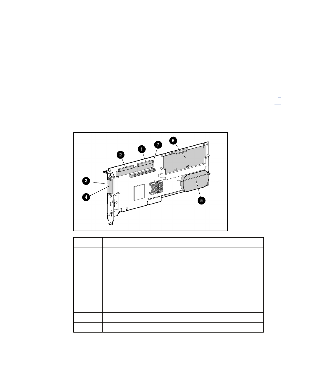
Board Components
Item ID Description
1 Internal SCSI connector, port A1 (do not use simultaneously with
item 3)
2 Internal SCSI connector, port A2 (do not use simultaneously with
item 4)
3 External SCSI connector, port A1 (do not use simultaneously with
item 1)
4 External SCSI connector, port A2 (do not use simultaneously with
item 2)
5 Controller battery
6 Battery-backed cache module
Page 8
8 HP Smart Array 6402 Controller for Integrity Servers User Guide
Item ID Description
7 Connector for expansion board
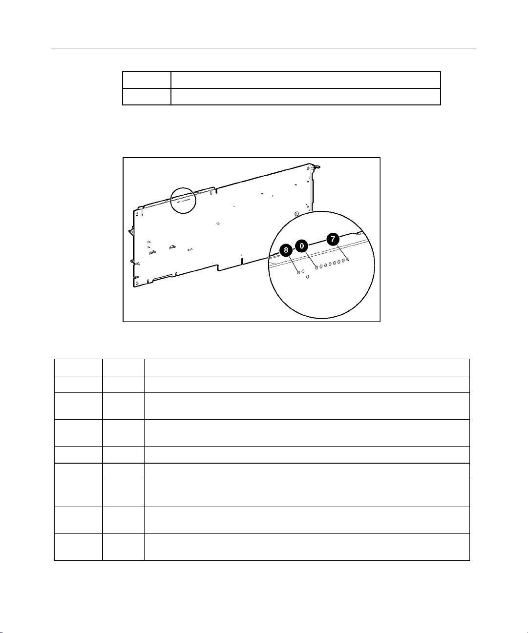
Controller Board Runtime LEDs
NOTE: During server power up, each runtime LED illuminates
randomly until POST has finished.
LED ID Color LED Name and Interpretation
0 Amber CR100: Diagnostics Error LED.
1 Amber CR101: Drive Failure LED. A physical drive connected to the controller has
failed.
2 Blue CR102: SCSI Bus Active LED. At least one of the SCSI buses on the controller
is active.
3 Green CR103: XOR Active LED. The controller is calculating parity data.
4 Green CR104: Command Outstanding LED. The controller is working on a command.
5 Blue CR105: Heartbeat LED. This LED flashes every 2.0 seconds, unless the
controller is malfunctioning.
6 Green CR106: Gas Pedal LED. This LED illuminates when the controller gets very
busy.
7 Green CR107: Idle Task LED. Under normal circumstances, this LED flashes every 1.0
seconds. When the controller is busy, the LED glows steadily.
Page 9
Hardware Features 9
LED ID Color LED Name and Interpretation
8 Amber CR11: Status Charging LED. The controller battery is being charged.
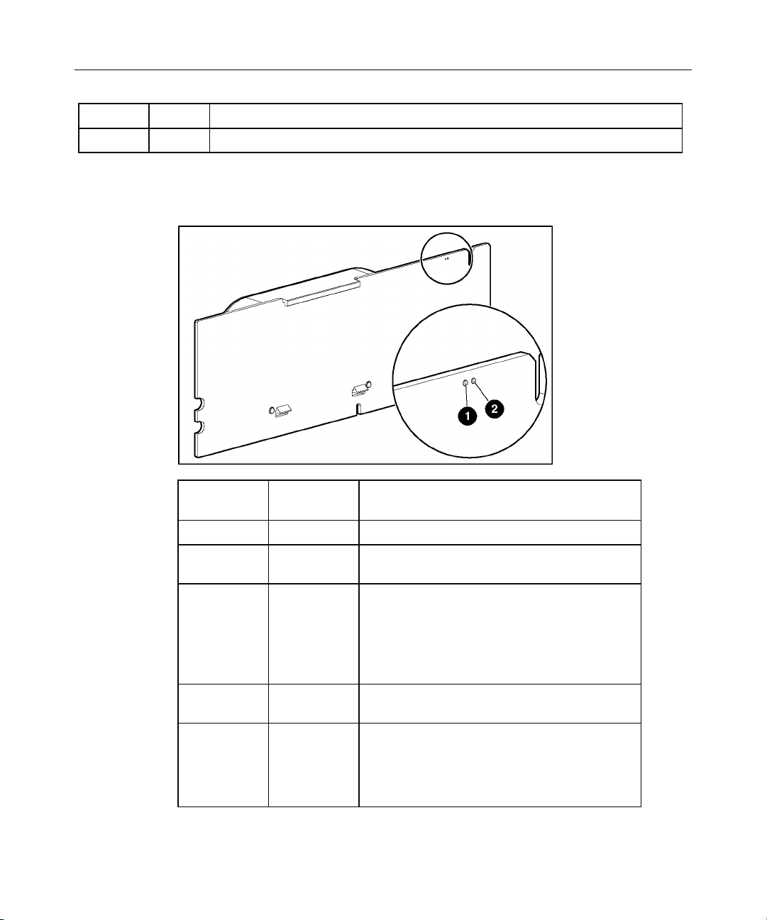
Cache Module LEDs
Item ID 1
Green LED
Steady glow -- The cache batteries are being charged.
Fast blink -- The cache microcontroller is waiting for the
-- Steady glow One of these conditions is present:
-- Fast blink There is an open circuit across the battery
-- Slow blink
Item ID 2
Amber LED
(once every
16 seconds)
Interpretation
host controller to communicate.
• There is a short circuit across the battery
terminals or within the battery pack.
• The host controller is updating the cache
microcontroller firmware.
terminals or within the battery pack.
This display pattern may occur after the
system is powered down. It indicates that the
cache contains data that has not yet been
written to the drives. Restore system power
within four days to prevent data loss.
Page 10

10 HP Smart Array 6402 Controller for Integrity Servers User Guide
Controller Specifications
Dimensions (excluding bracket) 31.2 cm x 10.7 cm x 1.8 cm (12.3 in x 4.2 in x 0.7 in)
Power required Less than 17 W
Ambient room temperature range Operating: 10° to 35°C (50° to 95°F)
Storage: -20° to 55°C (-4° to 131°F)
Relative humidity (noncondensing) Operating: 10% to 70%
Storage: 5% to 90%
RAID levels supported 0, 1+0, 5, ADG
Processor type PowerPC 405 at 266 MHz
DDR SDRAM bus transfer rate Up to 2.0 GB/s at 266 MHz (DDR, 72-bit)
Connector required on system board 3.3-V, 64-bit, Wide PCI-X or PCI slot
PCI-X transfer rate Up to 1.0 GB/s at 133 MHz (64-bit)
Number of SCSI channels 2 LVD-only
Maximum number of drives per
15 (14 in an external enclosure)
channel
SCSI connector type 68-pin Wide internal, VHDCI external
SCSI termination Required, but provided on Compaq and newer HP systems
SCSI transfer rate Up to 320 MB/s (160 MHz DDR) per channel
For more information about the controller features and specifications and for
information about system requirements, refer to the HP website
(http://www.hp.com/products/smartarray
).
Page 11

11
Overview of the Installation Procedure
In This Section
Installation in an Integrity Server Using Microsoft Windows......................................................11
Installation in an Integrity Server Using Microsoft Windows
The following steps summarize the procedure for installing the controller in an
Integrity server running Microsoft
the boot controller.
1. Install the controller hardware ("Installing the Controller Hardware" on page
13
).
2. Update the controller firmware ("Updating the Firmware" on page 19
3. Configure the logical boot drive, using ORCA ("Configuring an Array" on
page 21
).
4. If performing a manual installation, load the OEM boot driver ("Loading the
OEM Boot Driver" on page 27
5. Install the operating system.
6. If you are installing additional Smart Array controllers, install the latest
device drivers for each controller ("Installing Drivers for Additional
Controllers" on page 27
).
®
Windows® and configuring the controller as
).
).
7. Install ACU from the Smart Setup CD or DVD.
8. Install the Management Agents ("Installing the Management Agents" on
page 29
).
9. Create and format additional logical drives if desired, using ACU
("Configuring an Array" on page 21
).
The server is now ready to use.
Page 12

Page 13

13
Installing the Controller Hardware
In This Section
Before Beginning the Installation.................................................................................................13
Preparing the Server .....................................................................................................................13
Installing the Controller Board.....................................................................................................14
Connecting Storage Devices.........................................................................................................15
Before Beginning the Installation
Before beginning the installation procedure, visit the HP website
(http://www.hp.com/support
) to confirm that you have the latest version of each
driver and utility file needed. Compare the version numbers of the files there
with those of the same files on the software CD or DVD that is supplied in the
controller kit.
Preparing the Server
Before installing the controller in the server, back up all data. This step is
required if you are moving non-arrayed SCSI drives to a Smart Array controller,
because data is not preserved during a move between array controllers and nonarray controllers.
If the server supports hot-pluggable devices, you can install the controller board
without any further preparation ("Installing the Controller Board" on page 14
To prepare a server that does not support hot-pluggable devices:
1. Close all applications.
2. Power down the server.
).
Page 14

14 HP Smart Array 6402 Controller for Integrity Servers User Guide
CAUTION: In systems that use external data storage, be sure
that the server is the first unit to be powered down and the last to be
powered back up. Taking this precaution ensures that the system does
not erroneously mark the drives as failed when the server is powered
up.
3. Power down all peripheral devices that are attached to the server.
4. Unplug the AC power cord from the outlet and then from the server.
5. Disconnect all peripheral devices from the server.
Installing the Controller Board
WARNING: To reduce the risk of personal injury or
damage to the equipment, consult the safety information and user
documentation provided with the server before attempting the
installation.
Many servers are capable of providing energy levels that are
considered hazardous and are intended to be serviced only by
qualified personnel who have been trained to deal with these
hazards. Do not remove enclosures or attempt to bypass any
interlocks that may be provided for the purpose of removing these
hazardous conditions.
1. Remove or open the access panel.
2. Select an available 3.3-V PCI or PCI-X slot.
NOTE: In Integrity servers, the ID number of the slot in which you insert
the controller determines the boot controller order. Follow the
recommendations in the server-specific documentation to obtain the
required controller order.
3. Remove the slot cover or open the hot-plug latch. Save the retaining screw if
one is present.
4. Slide the controller board along the slot alignment guide, and press the board
firmly into the slot so that the contacts on the board edge are properly seated
in the system board connector.
5. Secure the controller board in place with the hot-plug latch or retaining
screw. If there is a guide latch on the rear of the board, close the latch.
Page 15

Installing the Controller Hardware 15
6. To finish installing the hardware, connect the internal and external drives
("Connecting Storage Devices" on page 15
).
Connecting Storage Devices
The controller supports Ultra2, Ultra160 (Ultra3), and Ultra320 drives.
Each peripheral that is connected to the controller must have a unique SCSI ID
value within the range of 0 to 15 (except ID 7, which is reserved for controller
use). This value determines the priority that is given to the device when it
attempts to use the SCSI bus.
The system automatically sets the SCSI IDs for hot-pluggable devices if they are
supported. For non-hot-pluggable devices, you must set the ID values manually
by using switches or jumpers on the device itself.
SCSI buses require termination on both ends to prevent signal degradation. In HP
ProLiant and Integrity servers, however, the controller, SCSI cable, and
backplane already provide this termination.
Connecting Internal Storage
1. If the storage device that you are adding is not hot-pluggable, power down
the system.
2. Install drives in the removable media bays on the server.
CAUTION: Do not use hot-pluggable drives on the same SCSI
bus as non-hot-pluggable drives.
NOTE: Drives that are to be grouped in the same array should all have
comparable capacity for efficient use of total storage capacity.
For additional information about drive installation, refer to the appropriate
section in this guide ("Replacing, Moving, or Adding Hard Drives" on page
37
) and consult the documentation that accompanied the drives.
When you have finished installing drives, continue with the next step.
− If the drives are hot-pluggable, go to step 3.
Page 16

16 HP Smart Array 6402 Controller for Integrity Servers User Guide
− If the drives are not hot-pluggable, go to step 4.
3. Attach the internal point-to-point SCSI cable (provided with the server) from
the internal connector of the controller to the hot-plug drive cage.
Installation of the hot-pluggable drives is complete.
4. For each SCSI bus, manually set the SCSI ID on each drive to a unique value
in the range of 0 to 15, except 7 (which is reserved for controller use). For
detailed instructions, consult the documentation that is provided with the
drive.
5. Attach a multi-device SCSI cable from the internal connector of the
controller to the non-hot-pluggable hard drives. (The cable may have been
provided with the server.)
6. Replace the access panel, and secure it with the thumbscrews if any are
present.
CAUTION: Do not operate the server for long periods without
the access panel. Operating the server without the access panel results
in improper airflow and improper cooling that can lead to thermal
damage.
Connecting External Storage
1. On the rear of the server, connect the external cable to the VHDCI connector
on the controller, and tighten the lock screws on the cable connector.
2. Attach the other end of the cable to the storage enclosure, and tighten the
lock screws on the cable connector.
SCSI Cable Part Numbers
NOTE: If you require additional cables, order them by the option kit
number.
Page 17

Installing the Controller Hardware 17
SCSI cable type Cable Length Option Kit
Number
Cable Assembly Number
External VHDCI cables for all
server models
Internal multi-device cable for
ProLiant servers
Internal cables for rx5670
servers (kit contains one
single-port cable and one
dual-port cable)
Internal cables for rx2600
servers (kit contains one
single-port cable and one
dual-port cable)
1.8 m (6 ft)
3.7 m (12 ft)
7.3 m (24 ft)
11.9 m (39 ft)
341174-B21
341175-B21
164604-B21
150214-B21
313374-001
313374-002
313374-004
313374-005
varies 166389-B21 148785-001
Single-port: 18 cm (7
in)
Dual-port: 20 cm (8 in)
Single-port: 49 cm (19
in)
Dual-port: 58 cm (23 in)
A9828A A9828-63001 (single-port)
A9828-63002 (dual-port)
A9827A A7231-63024 (single-port)
A7231-63025 (dual-port)
Page 18

Page 19

19
Updating the Firmware
In This Section
Using the Smart Components.......................................................................................................19
Using the Smart Components
To update the firmware, you can use Smart Components, also known as Online
ROM Flash Components ("Using the Components on the Website" on page 19
These components are available on the HP website
(http://www.hp.com/support/itaniumservers
software CD or DVD that is provided in the controller kit ("Using the Files on
the CD or DVD" on page 20
).
Because the Smart Components might be more recent than the firmware upgrade
files on the CD or DVD, check the Smart Components on the website before
using the updates on the CD or DVD.
Using the Components on the Website
1. Visit the HP website (http://www.hp.com/support/itaniumservers).
2. Locate the Smart Components for the operating system and controller that
the server is using.
3. Follow the instructions for installing the components. These instructions are
given on the same Web page as the components.
). Alternatively, you can use the
).
4. Follow the additional instructions that describe how to use the components to
flash the ROM. These instructions are provided with each component.
Page 20

20 HP Smart Array 6402 Controller for Integrity Servers User Guide
Using the Files on the CD or DVD
For an Integrity server using a supported Microsoft® Windows® operating system:
1. Insert the HP Smart Setup CD or DVD into the appropriate drive on the
server.
2. Locate the Windows
3. Double-click the icon for the utility. The utility opens and automatically
updates the firmware.
4. Reboot the server for the firmware updates to take effect.
For more information about Integrity servers, for technical support, or for
updated firmware, drivers, and utilities, refer to the HP website
(http://www.hp.com/support/itaniumservers
®
-based configuration utility on the CD or DVD.
).
Page 21

21
Configuring an Array
In This Section
Introduction ..................................................................................................................................21
Comparing the Utilities ................................................................................................................22
Using ORCA ................................................................................................................................23
Using ACU ...................................................................................................................................25
Introduction
HP provides two utilities for manually configuring an array on a Smart Array
controller:
• ACU—A versatile, browser-based utility that provides maximum control
over configuration parameters
• ORCA—A simple ROM-based configuration utility that runs on all
operating systems
NOTE: To copy a particular array configuration to several other servers
on the same network, use the scripting capability of ACU.
Whichever utility you use, the following limitations apply:
• For the most efficient use of drive space, do not mix drives of different
capacities within the same array. The configuration utility treats all physical
drives in an array as if they have the same capacity as the smallest drive in
the array. The excess capacity of any larger drives is wasted because it is
unavailable for data storage.
• The probability that an array will experience a drive failure increases with
the number of physical drives in the array. If you configure a logical drive
with RAID 5, keep the probability of failure low by using no more than 14
physical drives in the array.
For information about default array configuration settings, refer to the HP Array
Configuration Utility User Guide. This document is available on the
Documentation CD that is provided in the controller kit.
Page 22

22 HP Smart Array 6402 Controller for Integrity Servers User Guide
For conceptual information about arrays, logical drives, and fault-tolerance
methods, refer to "Drive Arrays and Fault-Tolerance Methods (on page 53
Comparing the Utilities
NOTE: In both tables, a y in the appropriate column indicates that the
feature or procedure is supported, while an n indicates that the feature
Supported Features ACU ORCA
Uses a graphical interface y n
Available in languages other than English y n
Executable at any time y n
Available on CD y n
or procedure is not supported.
)."
Uses a wizard to suggest the optimum configuration for an unconfigured
y n
controller
Describes configuration errors y n
Supported Procedures ACU ORCA
Creation and deletion of arrays and logical drives y y
Assignment of RAID level y y
Sharing of spare drives among several arrays y n
Assignment of multiple spare drives per array y n
Setting of stripe size y n
Migration of RAID level or stripe size y n
Configuration of controller settings y n
Expansion of an array y n
Creation of multiple logical drives per array y n
Setting of boot controller n y
Page 23

Configuring an Array 23
Using ORCA
NOTE: Before you power up the server in step 1, read through the
instructions for step 2 to determine which procedure you must follow to
start ORCA. The ORCA prompt persists for only a few seconds, and if
you do not start ORCA during this time, you must restart the server to
obtain the ORCA prompt again.
1. Power up the server. POST runs, and any array controllers that are in the
system are initialized one at a time.
2. Use the appropriate procedure to start ORCA:
− If you are accessing the server remotely using Telnet or HyperTerminal
on a Microsoft
®
Windows® 2000 or Windows NT® 4.0 system, press the
Esc + 8 keys when the Smart Array banner appears on the remote
console.
− If you are configuring the boot logical drive on a cell-based system,
execute a search all command at the EFI prompt. When the ORCA
prompt appears, press the F8 key.
− On all other systems, POST halts for several seconds during each
controller initialization process while an ORCA prompt message
appears. When you see the prompt, press the F8 key.
Page 24
24 HP Smart Array 6402 Controller for Integrity Servers User Guide
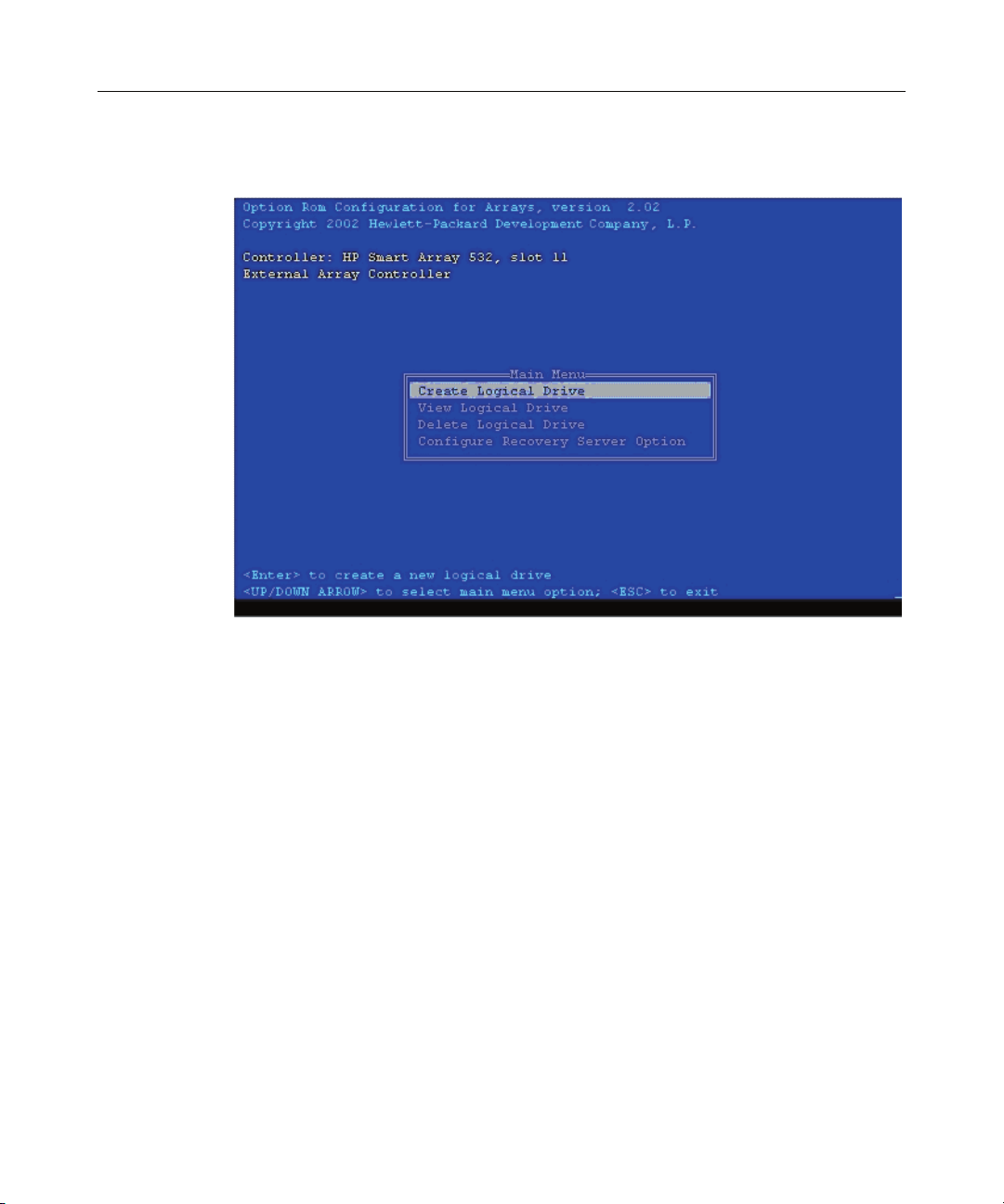
The ORCA main menu appears, enabling you to create, view, or delete a
logical drive.
To create a logical drive using ORCA:
1. Select Create Logical Drive.
The screen displays a list of all available (unconfigured) physical drives and
the valid RAID options for the system.
2. Use the Arrow keys, Spacebar, and Tab key to navigate around the screen
and set up the logical drive, including an online spare drive if one is required.
NOTE: You cannot use ORCA to configure one spare drive to be
shared among several arrays. Only ACU enables you to configure
shared spare drives.
While configuring the logical drive, one of the settings allows you to use
either 4 GB or 8 GB as the maximum boot drive size. Selecting 8 GB allows
a larger boot partition for operating systems such as Microsoft
Windows NT
®
4.0 that use cylinders, heads, and sectors of a physical drive to
®
determine the drive size. The larger boot drive size also lets you increase the
size of the logical drive at some later time. However, logical drive
performance is likely to decrease if the larger boot drive size is enabled.
Page 25

Configuring an Array 25
3. Press the Enter key to accept the settings.
4. Press the F8 key to confirm the settings and save the new configuration.
After several seconds, the Configuration Saved screen is displayed.
5. Press the Enter key to continue.
You can now create another logical drive by repeating the previous steps.
NOTE: Newly created logical drives are invisible to the operating
system. To make the new logical drives available for data storage,
format them using the instructions given in the operating system
documentation.
When you have finished creating the logical boot drive:
1. Exit ORCA.
2. From the EFI Boot Manager, select EFI Shell [Built-in].
3. Enter reset.
Using ACU
For detailed information about using ACU, refer to the HP Array Configuration
Utility User Guide. This document is available on the Documentation CD that is
provided in the controller kit.
Page 26

Page 27

27
Installing the Device Drivers
In This Section
Loading the OEM Boot Driver.....................................................................................................27
Installing Drivers for Additional Controllers ...............................................................................27
Loading the OEM Boot Driver
1. Launch EBSU. For detailed instructions, refer to the HP Smart Setup
Installation Poster for Microsoft Windows in the HP Integrity Server
Essentials Foundation Pack.
2. Select Load OEM Boot Driver.
3. At the prompt, select the controller model.
4. When the OEM boot driver has finished loading, exit EBSU.
Installing Drivers for Additional Controllers
IMPORTANT: If configuring a new server, install the operating system
before installing the device drivers. For operating system installation
instructions, refer to the operating system documentation.
If installing additional Smart Array controllers in the server, install the device
drivers for these controllers at the same time. For servers that use a supported
Microsoft
DVD that is provided in the controller kit.
1. Power down the server, and disconnect the power cords.
2. Install the new controller, and connect it to storage devices.
3. Power up the server.
4. In the Files Needed dialog box, select the option to automatically search for
®
Windows® operating system, these drivers are present on the CD or
The operating system recognizes the controller and launches the Found New
Hardware wizard.
the driver.
Page 28

28 HP Smart Array 6402 Controller for Integrity Servers User Guide
5. Insert the CD or DVD.
6. When the driver installation process is complete, click Finish to exit the
wizard, and then click Yes to confirm that you want to reboot the server.
7. Repeat the previous steps for each new controller that is to be installed in the
server.
Page 29

29
Installing the Management Agents
In This Section
Description of the Insight Management Agents ...........................................................................29
Installing the Agents.....................................................................................................................31
Description of the Insight Management Agents
The HP Insight Management Agents for Windows package consists of several
services and agents that are used to monitor and report the health of the server
and system components. The process memory use table ("Process Memory Used
by Insight Management Agents" on page 30
) lists the services and agents that are
provided in the package and installed on the system when the package is
installed.
For more information about Systems Insight Manager, refer to the HP website
(http://www.hp.com/go/hpsim
).
System Requirements for Insight Management Agents
Item Requirement
Operating system Microsoft® Windows® Server 2003 Enterprise Edition
or Datacenter Edition
Browser Microsoft® Internet Explorer 5.5 or later, Netscape 7.1,
or Mozilla 1.4
Device drivers All of the required HP-specific device drivers, except for
the MSA1000 driver (CPQFCAC.SYS), are installed
automatically when you install the agents.
Disk space At least 30 MB, if all agents are installed
Other required
items
SNMP
Page 30

30 HP Smart Array 6402 Controller for Integrity Servers User Guide
Process Memory Used by Insight Management Agents
This table shows the process memory used by the different Systems Insight
Management Agents and services on a system that has the minimum acceptable
configuration. The memory requirements for any differently-configured system
depend on many factors, such as the number of drives in the array, the capacity
and condition of the drives, and the configuration of the logical drives. As an
extreme example, the process memory that the HP Insight Storage Agent uses
increases by about 50 kB for every storage box that you connect to the system.
Service Description Process Memory
Requirement, MB
CpqWebMgmt HP Insight Web Agent 12
CpqNicMgmt HP Insight NIC Agent 7
CpMgHost HP Insight Foundation Agent 16
CqMgServ HP Insight Server Agent 6
CqMgStor HP Insight Storage Agent 6
CIMNTFY HP Insight Event Notifier 3
Asrsvc HP Insight Management
Automatic System Recovery
Service
Hpesysvc HP Insight Management Event
Synchronization Service
Hpevtsvc HP Insight Management Windows
Event Service
Hpler HP Insight Management Windows
Loopback Event Receiver
Hplersvc HP Insight Management Windows
Loopback Event Receiver Service
Hpmpsvc HP Insight Management
Processor Service
Hpmgtsvc HP Insight Management Service 3.0
Total agent memory use 83.4
4.5
5.2
5.6
7.5
2.4
5.2
Page 31

Installing the Management Agents 31
In addition, the SNMP service that must be present for the agents to operate uses
a further 16.0 kB of process memory.
Installing the Agents
1. If SNMP is not installed on the server:
a. Use the Add/Remove Programs utility in the Control Panel folder to
install SNMP from the Microsoft
®
Windows® distribution CD.
b. Reboot the server.
2. With the operating system running, insert the Smart Setup CD or DVD into
the appropriate drive in the server.
3. Click Software and Drivers for the server model.
4. Click HP Insight Management Agents.
5. Click HP Insight Management Agents for Integrity Servers with
Windows.
6. Double-click the executable file. Installation of the agents begins.
Page 32

Page 33

33
Upgrading or Replacing Controller Options
In This Section
Cache Module...............................................................................................................................33
Controller Battery Pack ................................................................................................................34
Cache Module
The cache module consists of a cache board and a battery pack.
WARNING: There is a risk of explosion, fire, or personal
injury if the battery pack is not properly handled. Refer to "Battery
Replacement Notice (on page
any item that contains a battery pack.
72)" before installing or removing
To remove the Cache Module: Open the DIMM ejector latches on each side of
the DIMM connector, and then pull the cache module out of the DIMM slot.
To replace the cache module, reverse this procedure.
Page 34

34 HP Smart Array 6402 Controller for Integrity Servers User Guide
To remove the Cache Battery Pack: Press down the retainer tabs and push
them through to the other side of the cache board, and then lift the battery pack
off the cache board.
To replace the cache battery pack, reverse this procedure.
Controller Battery Pack
WARNING: There is a risk of explosion, fire, or personal
injury if the battery pack is not properly handled. Refer to "Battery
Replacement Notice (on page
any item that contains a battery pack.
1. Unhook the wire retainer that holds the battery pack to the controller board.
72)" before installing or removing
Page 35

Upgrading or Replacing Controller Options 35
2. While holding the battery in one hand, pull the plastic retainer tabs upward
and push them through to the other side of the controller board.
To replace the controller battery pack, reverse this procedure.
Page 36

Page 37

37
Replacing, Moving, or Adding Hard Drives
In This Section
Identifying the Status of a Hard Drive..........................................................................................37
Recognizing Hard Drive Failure...................................................................................................39
Replacing Hard Drives .................................................................................................................41
Moving Drives and Arrays ...........................................................................................................45
Adding Drives ..............................................................................................................................47
Identifying the Status of a Hard Drive
When a drive is configured as a part of an array and connected to a powered-up
controller, the condition of the drive can be determined from the illumination
pattern of the hard drive status lights (LEDs). The table ("Hot-Plug SCSI Hard
Drive LED Combinations" on page 38
) describes the meanings of the different
illumination patterns.
Page 38

38 HP Smart Array 6402 Controller for Integrity Servers User Guide
Hot-Plug SCSI Hard Drive LED Combinations
Activity
LED (1)
Online
LED (2)
Fault LED
(3)
Interpretation
On, off, or
flashing
On, off, or
flashing
On or off Flashing A predictive failure alert has been received for this drive.
Replace the drive as soon as possible.
On Off The drive is online and is configured as part of an array.
If the array is configured for fault tolerance and all other drives in the
array are online, and a predictive failure alert is received or a drive
On or
Flashing Off
flashing
On Off Off
capacity upgrade is in progress, you may replace the drive online.
Do not remove the drive. Removing a drive may terminate the
current operation and cause data loss.
The drive is rebuilding or undergoing capacity expansion.
Do not remove the drive.
The drive is being accessed, but (1) it is not configured as part of an
array; (2) it is a replacement drive and rebuild has not yet started; or
Flashing Flashing Flashing
(3) it is spinning up during the POST sequence.
Do not remove the drive. Removing a drive may cause data loss
in non-fault-tolerant configurations.
Either (1) the drive is part of an array being selected by an array
configuration utility; (2) Drive Identification has been selected in
HP SIM; or (3) drive firmware is being updated.
Off Off On The drive has failed and has been placed offline.
You may replace the drive.
Off Off Off Either (1) the drive is not configured as part of an array; (2) the drive
is configured as part of an array, but it is a replacement drive that is
not being accessed or being rebuilt yet; or (3) the drive is configured
as an online spare.
If the drive is connected to an array controller, you may replace the
drive online.
Page 39

Replacing, Moving, or Adding Hard Drives 39
Recognizing Hard Drive Failure
A steadily glowing Fault LED indicates that that drive has failed. Other means by
which hard drive failure is revealed are:
• The amber LED on the front of a storage system illuminates if failed drives
are inside. (However, this LED also illuminates when other problems occur,
such as when a fan fails, a redundant power supply fails, or the system
overheats.)
• A POST message lists failed drives whenever the system is restarted, as long
as the controller detects at least one functional drive.
• ACU represents failed drives with a distinctive icon.
• Systems Insight Manager can detect failed drives remotely across a network.
(For more information about Systems Insight Manager, refer to the
documentation on the Management CD.)
• ADU lists all failed drives.
For additional information about diagnosing hard drive problems, refer to the HP
Servers Troubleshooting Guide.
CAUTION: Sometimes, a drive that has previously been failed
by the controller may seem to be operational after the system is powercycled or (for a hot-pluggable drive) after the drive has been removed
and reinserted. However, continued use of such marginal drives may
eventually result in data loss. Replace the marginal drive as soon as
possible.
Effects of a Hard Drive Failure
When a hard drive fails, all logical drives that are in the same array are affected.
Each logical drive in an array may be using a different fault-tolerance method, so
each logical drive can be affected differently.
• RAID 0 configurations cannot tolerate drive failure. If any physical drive in
the array fails, all non-fault-tolerant (RAID 0) logical drives in the same
array will also fail.
Page 40

40 HP Smart Array 6402 Controller for Integrity Servers User Guide
• RAID 1+0 configurations can tolerate multiple drive failures as long as no
failed drives are mirrored to one another.
• RAID 5 configurations can tolerate one drive failure.
• RAID ADG configurations can tolerate simultaneous failure of two drives.
Compromised Fault Tolerance
If more hard drives fail than the fault-tolerance method allows, fault tolerance is
compromised, and the logical drive fails. In this case, all requests from the
operating system are rejected with unrecoverable errors. You are likely to lose
data, although it can sometimes be recovered (refer to "Recovering from
Compromised Fault Tolerance" on page 40
One example of a situation in which compromised fault tolerance may occur is
when a drive in an array fails while another drive in the array is being rebuilt. If
the array has no online spare, any logical drives in this array that are configured
with RAID 5 fault tolerance will fail.
Compromised fault tolerance can also be caused by non-drive problems, such as
a faulty cable or temporary power loss to a storage system. In such cases, you do
not need to replace the physical drives. However, you may still have lost data,
especially if the system was busy at the time that the problem occurred.
).
Recovering from Compromised Fault Tolerance
If fault tolerance is compromised, inserting replacement drives does not improve
the condition of the logical volume. Instead, if the screen displays unrecoverable
error messages, perform the following procedure to recover data:
1. Power down the entire system, and then power it back up. In some cases, a
marginal drive will work again for long enough to enable you to make copies
of important files.
If a 1779 POST message is displayed, press the F2 key to re-enable the
logical volumes. Remember that data loss has probably occurred and any
data on the logical volume is suspect.
2. Make copies of important data, if possible.
Page 41

Replacing, Moving, or Adding Hard Drives 41
3. Replace any failed drives.
4. After you have replaced the failed drives, fault tolerance may again be
compromised. If so, cycle the power again. If the 1779 POST message is
displayed:
a. Press the F2 key to re-enable the logical drives.
b. Recreate the partitions.
c. Restore all data from backup.
To minimize the risk of data loss that is caused by compromised fault tolerance,
make frequent backups of all logical volumes.
Replacing Hard Drives
The most common reason for replacing a hard drive is that it has failed.
However, another reason is to gradually increase the storage capacity of the
entire system ("Upgrading Hard Drive Capacity" on page 44
If you insert a hot-pluggable drive into a drive bay while the system power is on,
all disk activity in the array pauses while the new drive is spinning up. This spinup process usually lasts for approximately 20 seconds. When the drive has
achieved its normal spin rate, data recovery to the replacement drive begins
automatically (as indicated by the blinking Online LED on the replacement
drive) if the array is in a fault-tolerant configuration.
).
If you replace a drive belonging to a fault-tolerant configuration while the system
power is off, a POST message is displayed when the system is next powered up.
This message prompts you to press the F1 key to start automatic data recovery. If
you do not enable automatic data recovery, the logical volume remains in a
ready-to-recover condition and the same POST message is displayed whenever
the system is restarted.
Factors to Consider Before Replacing Hard Drives
• In systems that use external data storage, be sure that the server is the first
unit to be powered down and the last to be powered back up. Taking this
precaution ensures that the system does not erroneously mark the drives as
failed when the server is powered up.
Page 42

42 HP Smart Array 6402 Controller for Integrity Servers User Guide
• If you set the SCSI ID jumpers manually:
− Check the ID value of the removed drive to be sure that it corresponds to
the ID of the drive marked as failed.
− Set the same ID value on the replacement drive to prevent SCSI ID
conflicts.
Before replacing a degraded drive:
• Open Systems Insight Manager and inspect the Error Counter window for
each physical drive in the same array to confirm that no other drives have
any errors. (For details, refer to the Systems Insight Manager documentation
on the Management CD.)
• Be sure that the array has a current, valid backup.
• Use replacement drives that have a capacity at least as great as that of the
smallest drive in the array. The controller immediately fails drives that have
insufficient capacity.
To minimize the likelihood of fatal system errors, take these precautions when
removing failed drives:
• Do not remove a degraded drive if any other drive in the array is offline (the
Online LED is off). In this situation, no other drive in the array can be
removed without data loss.
Exceptions:
− When RAID 1+0 is used, drives are mirrored in pairs. Several drives can
be in a failed condition simultaneously (and they can all be replaced
simultaneously) without data loss, as long as no two failed drives belong
to the same mirrored pair.
− When RAID ADG is used, two drives can fail simultaneously (and be
replaced simultaneously) without data loss.
− If the offline drive is a spare, the degraded drive can be replaced.
• Do not remove a second drive from an array until the first failed or missing
drive has been replaced and the rebuild process is complete. (The rebuild is
complete when the Online LED on the front of the drive stops blinking.)
These cases are the exceptions:
Page 43

Replacing, Moving, or Adding Hard Drives 43
− In RAID ADG configurations, any two drives in the array can be
replaced simultaneously.
− In RAID 1+0 configurations, any drives that are not mirrored to other
removed or failed drives can be simultaneously replaced offline without
data loss.
Automatic Data Recovery (Rebuild)
When you replace a hard drive in an array, the controller uses the fault-tolerance
information on the remaining drives in the array to reconstruct the missing data
(the data that was originally on the replaced drive) and write it to the replacement
drive. This process is called automatic data recovery, or rebuild. If fault tolerance
is compromised, this data cannot be reconstructed and is likely to be permanently
lost.
If another drive in the array fails while fault tolerance is unavailable during
rebuild, a fatal system error may occur, and all data on the array is then lost. In
exceptional cases, however, failure of another drive need not lead to a fatal
system error. These exceptions include:
• Failure after activation of a spare drive
• Failure of a drive that is not mirrored to any other failed drives (in a RAID
1+0 configuration)
• Failure of a second drive in a RAID ADG configuration
Time Required for a Rebuild
The time required for a rebuild varies considerably, depending on several factors:
• The priority that the rebuild is given over normal I/O operations (you can
change the priority setting by using ACU)
• The amount of I/O activity during the rebuild operation
• The rotational speed of the hard drives
• The availability of drive cache
• The brand, model, and age of the drives
• The amount of unused capacity on the drives
Page 44

44 HP Smart Array 6402 Controller for Integrity Servers User Guide
• The number of drives in the array (for RAID 5 and RAID ADG)
Allow approximately 15 minutes per gigabyte for the rebuild process to be
completed. This figure is conservative, and newer drive models usually require
less time to rebuild.
System performance is affected during the rebuild, and the system is unprotected
against further drive failure until the rebuild has finished. Therefore, replace
drives during periods of low activity when possible.
CAUTION: If the Online LED of the replacement drive stops
blinking and the amber Fault LED glows, or if other drive LEDs in the
array go out, the replacement drive has failed and is producing
unrecoverable disk errors. Remove and replace the failed replacement
drive.
When automatic data recovery has finished, the Online LED of the replacement
drive stops blinking and begins to glow steadily.
Failure of Another Drive During Rebuild
If a non-correctable read error occurs on another physical drive in the array
during the rebuild process, the Online LED of the replacement drive stops
blinking and the rebuild abnormally terminates.
If this situation occurs, reboot the server. The system may temporarily become
operational long enough to allow recovery of unsaved data. In any case, locate
the faulty drive, replace it, and restore data from backup.
Upgrading Hard Drive Capacity
You can increase the storage capacity on a system even if there are no available
drive bays by swapping drives one at a time for higher capacity drives. This
method is viable as long as a fault-tolerance method is running.
Page 45

Replacing, Moving, or Adding Hard Drives 45
CAUTION: Because it can take up to 15 minutes per gigabyte
to rebuild the data in the new configuration, the system is unprotected
against drive failure for many hours while a given drive is upgraded.
Perform drive capacity upgrades only during periods of minimal system
activity.
To upgrade hard drive capacity:
1. Back up all data.
2. Replace any drive. The data on the new drive is recreated from redundant
information on the remaining drives.
CAUTION: Do not replace any other drive until data rebuild on
this drive is complete.
3. When data on the new drive has been rebuilt (the Activity LED turns off),
repeat the previous step for the other drives in the array, one at a time.
When you have replaced all drives, you can use the extra capacity to either create
new logical drives or extend existing logical drives. For more information about
these procedures, refer to the HP Array Configuration Utility User Guide.
Moving Drives and Arrays
You can move drives to other ID positions on the same array controller. You can
also move a complete array from one controller to another, even if the controllers
are on different servers.
Before you move drives, the following conditions must be met:
• If moving the drives to a different server, the new server must have enough
empty bays to accommodate all the drives simultaneously.
• The move will not result in more than 14 physical drives per controller
channel.
• No controller will be configured with more than 32 logical volumes.
• The array has no failed or missing drives.
• The array is in its original configuration.
Page 46

46 HP Smart Array 6402 Controller for Integrity Servers User Guide
• The controller is not reading from or writing to any of the spare drives in the
array.
• The controller is not running capacity expansion, capacity extension, or
RAID or stripe size migration.
• The controller is using the latest firmware version (recommended).
If you want to move an array to another controller, you must also consider the
following additional limitations:
• All drives in the array must be moved at the same time.
• In most cases, a moved array (and the logical drives that it contains) can still
undergo array capacity expansion, logical drive capacity extension, or
migration of RAID level or stripe size. An exception occurs when the array
meets all of these conditions:
− It was originally created on a SMART-2/P, SMART-2DH, SA-3200,
SA-3100ES, SA-4200, SA-4250ES, or SA-530x controller.
− It is moved to a controller that does not have a battery-backed cache.
− It has less than 4 MB of unused capacity.
• If a controller contains a RAID ADG logical volume, none of the arrays on
the controller can be moved directly to a controller that does not support
RAID ADG. The arrays can be moved indirectly, as described by the
instructions in this section.
When all the conditions have been met:
1. Back up all data before removing any drives or changing configuration. This
step is required if you are moving data-containing drives from a controller
that does not have a battery-backed cache.
2. Power down the system.
3. If you are moving an array from a controller that contains a RAID ADG
logical volume to a controller that does not support RAID ADG:
a. Remove or disconnect the drives that contain the RAID ADG logical
volume.
b. Reboot the server.
Page 47

Replacing, Moving, or Adding Hard Drives 47
c. Open ACU and navigate to the controller that contained the RAID ADG
volume.
ACU displays the missing RAID ADG volume using a different icon to
indicate that the volume is unavailable.
d. Delete the RAID ADG volume.
e. Accept the configuration change, and then close ACU.
f. Power down the system.
4. Move the drives.
5. Power up the system. If a 1724 POST message is displayed, drive positions
were changed successfully and the configuration was updated.
If a 1785 (Not Configured) POST message is displayed:
a. Power down the system immediately to prevent data loss.
b. Return the drives to their original locations.
c. Restore the data from backup, if necessary.
6. Check the new drive configuration by running ORCA or ACU ("Configuring
an Array" on page 21
).
Adding Drives
You can add hard drives to a system at any time, as long as you do not exceed the
maximum number of drives that the controller supports. You can then either
build a new array from the added drives or use the extra storage capacity to
expand the capacity of an existing array.
To perform an array capacity expansion, use ACU. If the system is using hotpluggable drives, you can expand array capacity without shutting down the
operating system (that is, with the server online) if ACU is running in the same
environment as the normal server applications. (For more information, refer to
the HP Array Configuration Utility User Guide.)
Page 48

48 HP Smart Array 6402 Controller for Integrity Servers User Guide
The expansion process is illustrated in the following figure, in which the original
array (containing data) is shown with a dashed border and the newly added drives
(containing no data) are shown unshaded. The array controller adds the new
drives to the array and redistributes the original logical drives over the enlarged
array one logical drive at a time. This process liberates some storage capacity on
each of the physical drives in the array. During this procedure, the logical drives
each keep the same fault-tolerance method in the enlarged array that they had in
the smaller array.
When the expansion process has finished, you can use the liberated storage
capacity on the enlarged array to create new logical drives. Alternatively, you
can enlarge one of the original logical drives. This latter process is called logical
drive capacity extension and is also carried out using ACU.
Page 49

49
Diagnosing Array Problems
In This Section
Diagnostic Tools...........................................................................................................................49
Diagnostic Tools
Several diagnostic tools provide feedback about problems with arrays. The most
important are:
• ADU
This utility can be downloaded from the HP website
(http://www.hp.com/support
messages are provided in the HP Servers Troubleshooting Guide.
• POST messages
Smart Array controllers produce diagnostic error messages at reboot. Many
of these POST messages are self-explanatory and suggest corrective actions.
For more information about POST messages, refer to the HP Servers
Troubleshooting Guide.
• Offline Diagnostics and Utilities
This set of tools for Integrity servers is available on the CD or DVD that is
supplied in the controller kit. To use one of these tools, insert the CD or
DVD into the appropriate server drive and follow the on-screen prompts and
instructions.
). The meanings of the various ADU error
Page 50

Page 51

51
Probability of Logical Drive Failure
In This Section
Factors Involved in Logical Drive Failure....................................................................................51
Factors Involved in Logical Drive Failure
The probability that a logical drive will fail depends on the RAID level setting
and on the number and type of physical drives in the array. If the logical drive
does not have an online spare, the following results apply:
• A RAID 0 logical drive fails if only one physical drive fails.
• A RAID 1+0 logical drive fails if any two failed physical drives are mirrored
to each other.
− The maximum number of physical drives that can fail without causing
failure of the logical drive is n/2, where n is the number of hard drives in
the array. In practice, a logical drive usually fails before this maximum is
reached. As the number of failed physical drives increases, it becomes
increasingly likely that the newly failed drive is mirrored to a previously
failed drive.
− The minimum number of physical drive failures that can cause the
logical drive to fail is two. This situation occurs when the two failed
drives are mirrored to each other. As the total number of drives in the
array increases, the probability that the only two failed drives in an array
are mirrored to each other decreases.
• A RAID 5 logical drive fails if two physical drives fail.
• A RAID ADG logical drive fails when three physical drives fail.
Page 52

52 HP Smart Array 6402 Controller for Integrity Servers User Guide
At any given RAID level, the probability of logical drive failure increases as the
number of physical drives in the logical drive increases. This is illustrated more
quantitatively in the graph ("Probability of Logical Drive Failure vs. Number of
Drives in Array" on page 52
). The data for this graph is calculated from the
MTBF value for a typical physical drive, assuming that no online spares are
present. If an online spare is added to any of the fault-tolerant RAID
configurations, the probability of logical drive failure is further decreased.
Probability of Logical Drive Failure vs. Number of Drives in Array
Page 53

53
Drive Arrays and Fault-Tolerance Methods
In This Section
Drive Arrays .................................................................................................................................53
Fault-Tolerance Methods..............................................................................................................56
Drive Arrays
The capacity and performance of a single physical (hard) drive is adequate for
home users. However, business users demand higher storage capacities, higher
data transfer rates, and greater protection against data loss when drives fail.
Connecting extra physical drives (Pn in the figure) to a system increases the total
storage capacity but has no effect on the efficiency of read/write (R/W)
operations. Data can still be transferred to only one physical drive at a time.
Page 54

54 HP Smart Array 6402 Controller for Integrity Servers User Guide
With an array controller installed in the system, the capacity of several physical
drives can be combined into one or more virtual units called logical drives (also
called logical volumes and denoted by Ln in the figures in this section). Then,
the read/write heads of all the constituent physical drives are active
simultaneously, reducing the total time required for data transfer.
Because the read/write heads are active simultaneously, the same amount of data
is written to each drive during any given time interval. Each unit of data is called
a block (denoted by Bn in the figure), and adjacent blocks form a set of data
stripes (Sn) across all the physical drives that comprise the logical drive.
Page 55

Drive Arrays and Fault-Tolerance Methods 55
For data in the logical drive to be readable, the data block sequence must be the
same in every stripe. This sequencing process is performed by the array
controller, which sends the data blocks to the drive write heads in the correct
order.
A natural consequence of the striping process is that each physical drive in a
given logical drive will contain the same amount of data. If one physical drive
has a larger capacity than other physical drives in the same logical drive, the
extra capacity is wasted because it cannot be used by the logical drive.
The group of physical drives containing the logical drive is called a drive array,
or just array (denoted by An in the figure). Because all the physical drives in an
array are commonly configured into just one logical drive, the term array is often
used as a synonym for logical drive. However, an array can contain several
logical drives, each of a different size.
Each logical drive in an array is distributed across all of the physical drives
within the array. A logical drive can also extend across more than one port on the
same controller, but it cannot extend across more than one controller.
Drive failure, although rare, is potentially catastrophic. For arrays that are
configured as shown in the previous figure, failure of any physical drive in the
array causes every logical drive in the array to suffer irretrievable data loss. To
protect against data loss due to physical drive failure, logical drives are
configured with fault tolerance ("Fault-Tolerance Methods" on page 56
).
Page 56

56 HP Smart Array 6402 Controller for Integrity Servers User Guide
For any configuration except RAID 0, further protection against data loss can be
achieved by assigning a drive as an online spare (or hot spare). This drive
contains no data and is connected to the same controller as the array. When any
other physical drive in the array fails, the controller automatically rebuilds
information that was originally on the failed drive to the online spare. The system
is thus restored to full RAID-level data protection, although it now no longer has
an online spare. (However, in the unlikely event that another drive in the array
fails while data is being rewritten to the spare, the logical drive will still fail.)
When you configure an online spare, it is automatically assigned to all logical
drives in the same array. Additionally, you do not need to assign a separate
online spare to each array. Instead, you can configure one hard drive to be the
online spare for several arrays if the arrays are all on the same controller.
Fault-Tolerance Methods
Several fault-tolerance methods exist. Those most often used with Smart Array
controllers are hardware-based RAID methods.
Two alternative fault-tolerance methods that are sometimes used are also
described ("Alternative Fault-Tolerance Methods" on page 62
hardware-based RAID methods provide a much more robust and controlled faulttolerance environment, so these alternative methods are seldom used.
). However,
Hardware-Based Fault-Tolerance Methods
The hardware-based methods that are recommended for use with Smart Array
controllers are:
• RAID 0—Data Striping only (no fault tolerance)
• RAID 1+0—Drive Mirroring
• RAID 5—Distributed Data Guarding
• RAID ADG—Advanced Data Guarding
Page 57

Drive Arrays and Fault-Tolerance Methods 57
RAID 0—No Fault Tolerance
A RAID 0 configuration provides data striping, but there is no protection against
data loss when a drive fails. However, it is useful for rapid storage of large
amounts of noncritical data (for printing or image editing, for example) or when
cost is the most important consideration.
Advantages:
• Has the highest write performance of all RAID methods.
• Has the lowest cost per unit of stored data of all RAID methods.
• All drive capacity is used to store data (none is needed for fault tolerance).
Disadvantages:
• All data on the logical drive is lost if a physical drive fails.
• Cannot use an online spare.
• Can only preserve data by backing it up to external drives.
RAID 1+0—Drive Mirroring
In a RAID 1+0 configuration, data is duplicated to a second drive.
Page 58

58 HP Smart Array 6402 Controller for Integrity Servers User Guide
When the array has more than two physical drives, drives are mirrored in pairs.
In each mirrored pair, the physical drive that is not busy answering other requests
answers any read requests that are sent to the array. (This behavior is called load
balancing.) If a physical drive fails, the remaining drive in the mirrored pair can
still provide all the necessary data. Several drives in the array can fail without
incurring data loss, as long as no two failed drives belong to the same mirrored
pair.
This fault-tolerance method is useful when high performance and data protection
are more important than the cost of physical drives.
Page 59

Drive Arrays and Fault-Tolerance Methods 59
NOTE: When there are only two physical drives in the array, this fault-
tolerance method is often referred to as RAID 1.
Advantages:
• Has the highest read performance of any fault-tolerant configuration.
• No data is lost when a drive fails, as long as no failed drive is mirrored to
another failed drive (up to half of the physical drives in the array can fail).
Disadvantages:
• This method is expensive (many drives are needed for fault tolerance).
• Only half of the total drive capacity is usable for data storage.
RAID 5—Distributed Data Guarding
In a RAID 5 configuration, data protection is provided by parity data (denoted
by Px,y in the figure). This parity data is calculated stripe by stripe from the user
data that is written to all other blocks within that stripe. The blocks of parity data
are distributed evenly over every physical drive within the logical drive.
When a physical drive fails, data that was on the failed drive can be calculated
from the remaining parity data and user data on the other drives in the array. This
recovered data is usually written to an online spare in a process called a rebuild.
Page 60

60 HP Smart Array 6402 Controller for Integrity Servers User Guide
This configuration is useful when cost, performance, and data availability are
equally important.
Advantages:
• Has high read performance.
• Data is not lost if one physical drive fails.
• More drive capacity is usable than with RAID 1+0—parity information
requires only the storage space equivalent to one physical drive.
Disadvantages:
• Has relatively low write performance.
• Data is lost if a second drive fails before data from the first failed drive is
rebuilt.
RAID ADG—Advanced Data Guarding
NOTE: Not all controllers support RAID ADG.
RAID ADG, like RAID 5, generates and stores parity information to protect
against data loss caused by drive failure. With RAID ADG, however, two
different sets of parity data are used (denoted by Px,y and Qx,y in the figure),
allowing data to still be preserved if two drives fail. Each set of parity data uses a
capacity equivalent to that of one of the constituent drives.
Page 61

Drive Arrays and Fault-Tolerance Methods 61
This method is most useful when data loss is unacceptable but cost is also an
important factor. The probability that data loss will occur when an array is
configured with RAID ADG is less than it would be if it were configured with
RAID 5.
Advantages:
• Has a high read performance.
• Allows high data availability—any two drives can fail without loss of critical
data.
• More drive capacity is usable than with RAID 1+0—parity information
requires only the storage space equivalent to two physical drives.
Disadvantages:
The main disadvantage of RAID ADG is a relatively low write-performance
(lower than RAID 5), because of the need for two sets of parity data.
Comparing the Hardware-Based RAID Methods
Item RAID 0 RAID 1+0 RAID 5 RAID ADG
Alternative name Striping
Formula for number of drives
usable for data (n = total number of
drives in array)
Fraction of drive space usable* 100% 50% 67% to 93% 50% to 96%
Minimum number of physical drives 1 2 3 4
Tolerates failure of one physical
drive
Tolerates simultaneous failure of
more than one physical drive
Read performance High High High High
NOTE: Not all controllers support RAID ADG.
Mirroring Distributed
(no fault
tolerance)
n n/2 n-1 n-2
No Yes Yes Yes
No Only if no two
failed drives are
in the same
mirrored pair
Advanced
Data
Guarding
No Yes
Data
Guarding
Page 62

62 HP Smart Array 6402 Controller for Integrity Servers User Guide
Item RAID 0 RAID 1+0 RAID 5 RAID ADG
Write performance High Medium Low Low
Relative cost Low High Medium Medium
*Values for the fraction of drive space usable are calculated with these assumptions: (1)
all physical drives in the array have the same capacity; (2) online spares are not used; (3)
no more than 14 physical drives are used per array for RAID 5; and (4) no more than 56
drives are used with RAID ADG.
Selecting a RAID Method
Most Important Criterion Also Important Suggested RAID Level
Fault tolerance Cost effectiveness
Cost effectiveness Fault tolerance
I/O performance Cost effectiveness
NOTE: Not all controllers support RAID ADG.
RAID ADG
I/O performance
I/O performance
Fault tolerance
RAID 1+0
RAID ADG
RAID 5 (RAID 0 if fault tolerance is not required)
RAID 5 (RAID 0 if fault tolerance is not required)
RAID 1+0
Alternative Fault-Tolerance Methods
Your operating system may also support software-based RAID or controller
duplexing.
• Software-based RAID resembles hardware-based RAID, except that the
operating system works with logical drives as if they were physical drives.
To protect against data loss caused by physical drive failure, each logical
drive must be in a different array from the others.
• Controller duplexing uses two identical controllers with independent,
identical sets of drives containing identical data. In the unlikely event of a
controller failure, the remaining controller and drives will service all
requests.
Page 63

Drive Arrays and Fault-Tolerance Methods 63
Neither of these alternative fault-tolerance methods supports online spares or
automatic data recovery, nor do they support auto-reliability monitoring or
interim data recovery.
If you decide to use one of these alternative methods, configure your arrays with
RAID 0 for maximum storage capacity and refer to your operating system
documentation for further implementation details.
Page 64

Page 65

65
Electrostatic Discharge
In This Section
Preventing Electrostatic Discharge...............................................................................................65
Grounding Methods to Prevent Electrostatic Discharge...............................................................66
Preventing Electrostatic Discharge
To prevent damaging the system, be aware of the precautions you need to follow
when setting up the system or handling parts. A discharge of static electricity
from a finger or other conductor may damage system boards or other staticsensitive devices. This type of damage may reduce the life expectancy of the
device.
To prevent electrostatic damage:
• Avoid hand contact by transporting and storing products in static-safe
containers.
• Keep electrostatic-sensitive parts in their containers until they arrive at static-
free workstations.
• Place parts on a grounded surface before removing them from their
containers.
• Avoid touching pins, leads, or circuitry.
• Always be properly grounded when touching a static-sensitive component or
assembly.
Page 66

66 HP Smart Array 6402 Controller for Integrity Servers User Guide
Grounding Methods to Prevent Electrostatic Discharge
Several methods are used for grounding. Use one or more of the following
methods when handling or installing electrostatic-sensitive parts:
• Use a wrist strap connected by a ground cord to a grounded workstation or
computer chassis. Wrist straps are flexible straps with a minimum of
1 megohm ±10 percent resistance in the ground cords. To provide proper
ground, wear the strap snug against the skin.
• Use heel straps, toe straps, or boot straps at standing workstations. Wear the
straps on both feet when standing on conductive floors or dissipating floor
mats.
• Use conductive field service tools.
• Use a portable field service kit with a folding static-dissipating work mat.
If you do not have any of the suggested equipment for proper grounding, have an
authorized reseller install the part.
For more information on static electricity or assistance with product installation,
contact your authorized reseller.
Page 67

67
Regulatory Compliance Notices
In This Section
Federal Communications Commission Notice .............................................................................67
Canadian Notice (Avis Canadien) ................................................................................................70
European Union Notice ................................................................................................................70
BSMI Notice.................................................................................................................................71
Japanese Notice ............................................................................................................................71
Korean Class A Notice .................................................................................................................72
Korean Class B Notice .................................................................................................................72
Battery Replacement Notice.........................................................................................................72
Federal Communications Commission Notice
Part 15 of the Federal Communications Commission (FCC) Rules and
Regulations has established Radio Frequency (RF) emission limits to provide an
interference-free radio frequency spectrum. Many electronic devices, including
computers, generate RF energy incidental to their intended function and are,
therefore, covered by these rules. These rules place computers and related
peripheral devices into two classes, A and B, depending upon their intended
installation. Class A devices are those that may reasonably be expected to be
installed in a business or commercial environment. Class B devices are those that
may reasonably be expected to be installed in a residential environment (for
example, personal computers). The FCC requires devices in both classes to bear
a label indicating the interference potential of the device as well as additional
operating instructions for the user.
FCC Rating Label
The FCC rating label on the device shows the classification (A or B) of the
equipment. Class B devices have an FCC logo or ID on the label. Class A
devices do not have an FCC logo or ID on the label. After you determine the
class of the device, refer to the corresponding statement.
Page 68

68 HP Smart Array 6402 Controller for Integrity Servers User Guide
Class A Equipment
This equipment has been tested and found to comply with the limits for a Class A
digital device, pursuant to Part 15 of the FCC Rules. These limits are designed to
provide reasonable protection against harmful interference when the equipment is
operated in a commercial environment. This equipment generates, uses, and can
radiate radio frequency energy and, if not installed and used in accordance with
the instructions, may cause harmful interference to radio communications.
Operation of this equipment in a residential area is likely to cause harmful
interference, in which case the user will be required to correct the interference at
personal expense.
Class B Equipment
This equipment has been tested and found to comply with the limits for a Class B
digital device, pursuant to Part 15 of the FCC Rules. These limits are designed to
provide reasonable protection against harmful interference in a residential
installation. This equipment generates, uses, and can radiate radio frequency
energy and, if not installed and used in accordance with the instructions, may
cause harmful interference to radio communications. However, there is no
guarantee that interference will not occur in a particular installation. If this
equipment does cause harmful interference to radio or television reception, which
can be determined by turning the equipment off and on, the user is encouraged to
try to correct the interference by one or more of the following measures:
• Reorient or relocate the receiving antenna.
• Increase the separation between the equipment and receiver.
• Connect the equipment into an outlet on a circuit that is different from that to
which the receiver is connected.
• Consult the dealer or an experienced radio or television technician for help.
Page 69

Regulatory Compliance Notices 69
Declaration of Conformity for Products Marked with the FCC Logo, United States Only
This device complies with Part 15 of the FCC Rules. Operation is subject to the
following two conditions: (1) this device may not cause harmful interference, and
(2) this device must accept any interference received, including interference that
may cause undesired operation.
For questions regarding this product, contact us by mail or telephone:
• Hewlett-Packard Company
P. O. Box 692000, Mail Stop 530113
Houston, Texas 77269-2000
• 1-800-652-6672 (For continuous quality improvement, calls may be
recorded or monitored.)
For questions regarding this FCC declaration, contact us by mail or telephone:
• Hewlett-Packard Company
P. O. Box 692000, Mail Stop 510101
Houston, Texas 77269-2000
• 1-281-514-3333
To identify this product, refer to the part, series, or model number found on the
product.
Modifications
The FCC requires the user to be notified that any changes or modifications made
to this device that are not expressly approved by Hewlett-Packard Company may
void the user’s authority to operate the equipment.
Cables
Connections to this device must be made with shielded cables with metallic
RFI/EMI connector hoods in order to maintain compliance with FCC Rules and
Regulations.
Page 70

70 HP Smart Array 6402 Controller for Integrity Servers User Guide
Canadian Notice (Avis Canadien)
Class A Equipment
This Class A digital apparatus meets all requirements of the Canadian
Interference-Causing Equipment Regulations.
Cet appareil numérique de la classe A respecte toutes les exigences du
Règlement sur le matériel brouilleur du Canada.
Class B Equipment
This Class B digital apparatus meets all requirements of the Canadian
Interference-Causing Equipment Regulations.
Cet appareil numérique de la classe B respecte toutes les exigences du Règlement
sur le matériel brouilleur du Canada.
European Union Notice
Products bearing the CE marking comply with the EMC Directive (89/336/EEC)
and the Low Voltage Directive (73/23/EEC) issued by the Commission of the
European Community and, if this product has telecommunication functionality,
the R&TTE Directive (1999/5/EC).
Compliance with these directives implies conformity to the following European
Norms (in parentheses are the equivalent international standards and regulations):
• EN 55022 (CISPR 22)—Electromagnetic Interference
• EN55024 (IEC61000-4-2, 3, 4, 5, 6, 8, 11)—Electromagnetic Immunity
• EN 60950 (IEC60950)—Product Safety
Page 71

Regulatory Compliance Notices 71
BSMI Notice
Japanese Notice
Page 72

72 HP Smart Array 6402 Controller for Integrity Servers User Guide
Korean Class A Notice
Class A Equipment
Korean Class B Notice
Class B Equipment
Battery Replacement Notice
This component uses a nickel metal hydride (NiMH) battery pack.
WARNING: There is a risk of explosion, fire, or personal
injury if a battery pack is mishandled. To reduce this risk:
Page 73

Regulatory Compliance Notices 73
• Do not attempt to recharge the batteries if they are
disconnected from the controller.
• Do not expose the battery pack to water, or to temperatures
higher than 60°C (140°F).
• Do not abuse, disassemble, crush, or puncture the battery
pack.
• Do not short the external contacts.
• Replace the battery pack only with the designated HP spare.
Battery disposal should comply with local regulations.
Batteries, battery packs, and accumulators should not be
disposed of together with the general household waste. To
forward them to recycling or proper disposal, use the public
collection system or return them by established parts return
methods to HP, an authorized HP Partner, or one of their agents.
For more information about battery replacement or proper disposal, contact an
authorized reseller or an authorized service provider.
Page 74

Page 75

75
Acronyms and Abbreviations
ACU
Array Configuration Utility
ADG
Advanced Data Guarding
ADU
Array Diagnostics Utility
DIMM
dual inline memory module
EBSU
EFI-based setup utility
EFI
extensible firmware interface
ESD
electrostatic discharge
EULA
end user license agreement
Page 76

76 HP Smart Array 6402 Controller for Integrity Servers User Guide
LED
light-emitting diode
MSA
Modular Smart Array
MTBF
mean time between failures
OEM
original equipment manufacturer
ORCA
Option ROM Configuration for Arrays
PCI-X
peripheral component interconnect extended
POST
Power-On Self-Test
RAID
redundant array of inexpensive (or independent) disks
RBSU
ROM-Based Setup Utility
SA
Smart Array
Page 77

Acronyms and Abbreviations 77
SIM
Systems Insight Manager
SNMP
Simple Network Management Protocol
VHDCI
very high density cable interconnect
Page 78

Page 79

79
device priority, setting 15
Index
A
diagnostic tools 49
drive array concepts 53
drive LEDs 37
drives, connecting 15
duplexing 62
adding drives 47
ADU (Array Diagnostics Utility) 49
array capacity expansion 47
array concepts 53
array controller installation overview 11
array, configuring 21
assembly numbers, cables 16
automatic data recovery (rebuild) 41, 43
B
battery 7, 72
battery pack, removing 34
board components 7
BSMI notice 71
C
cable part numbers 16
cables 69
cache module LEDs 9
cache, features of 9
Canadian Notice 70
compromised fault tolerance 40
configuring an array 21
controller board, features of 7
controller board, installing 13
controller duplexing 62
controller installation, overview of 11
controller LEDs 8
D
data protection methods 56, 62
data recovery 40, 43
data transfer rate 10
Declaration of Conformity 69
E
electrostatic discharge 65
environmental requirements 10
error messages 39, 49
European Union notice 70
expanding an array 47
extending logical drive capacity 47
external cables 16
external drives, installing 16
F
failure of hard drive 39, 44
fault tolerance, compromised 40
fault-tolerance methods 56
Federal Communications Commission (FCC)
Notice 67, 69
firmware, updating 19
G
grounding methods 66
H
hard drive LEDs 37, 38
hard drive, adding 47
hard drive, failure of 39
hard drive, replacing 41
hard drives 38
hard drives, adding 47
hard drives, determining status of 37
hard drives, installing 15
hard drives, types supported 15
Page 80

80 HP Smart Array 6402 Controller for Integrity Servers User Guide
I
internal cables 16
internal drives, installing 15
J
Japanese notice 71
K
Korean Class B notice 72
L
LEDs, cache module 9
LEDs, controller 8
LEDs, hard drive 37
logical drive capacity extension 47
logical drive, creating 21, 53
logical drive, description of 53
logical drive, failure of 51
M
Management Agents, updating 29
N
non-hot-pluggable drives, using 15
R
RAID levels 56
RAID levels, comparison of features 61
RAID, software-based 62
rebuild 43
regulatory compliance notices 67
replacing hard drives 37, 41
ROM, updating 19
S
SCSI bus termination 15
SCSI cabling 15
SCSI IDs 15
software-based RAID 62
specifications, controller 10
static electricity 65
status lights, cache module 9
status lights, controller 8
status lights, hard drive 37
storage devices, connecting 15
storage, external 16
T
temperature requirements 10
termination of SCSI bus 15
troubleshooting 49
O
option kit, cables 16
ORCA (Option ROM Configuration for
Arrays) 23
overview of installation process 11
P
part numbers, cables 16
POST error messages 39, 49
power requirements 10
U
updating the firmware 19
upgrading drive capacity 44
 Loading...