

Page 1

Please check out our eBay auctions for more great
deals on Factory Service Manuals:
Page 2
Presario 1700 Series
Models: XL260, XL261, XL262, XL264, XL265, XL266, XL274, XL275, XL360, XL361,
XL362, XL363, XL364, XL365, XL366, XL367, XL368, XL369, XL370, XL371, XL372, XL373,
XL374, XL375, XL376, XL377, and XL378
Removal Sequence
This section explains the removal and replacement procedures for the 1700XL unit.
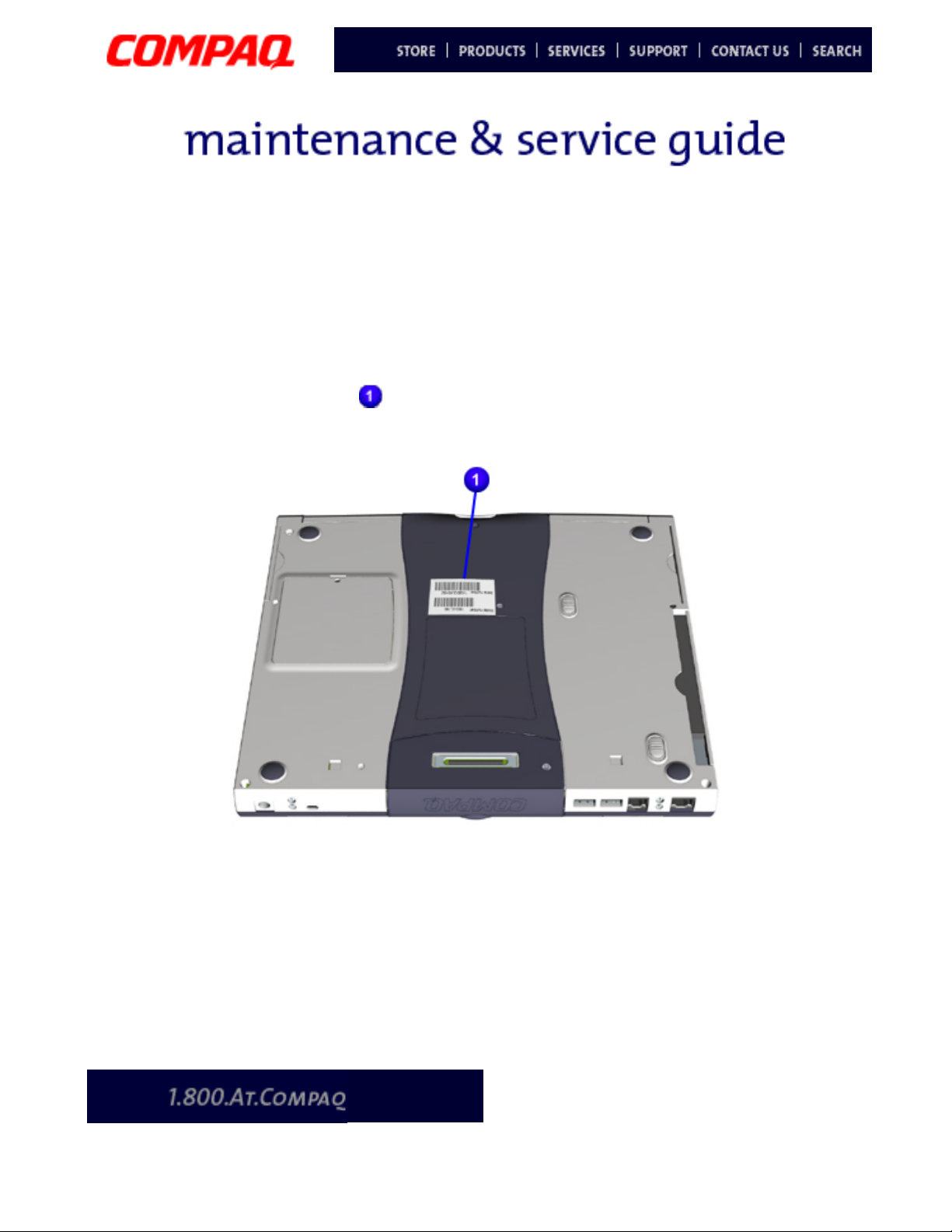
Serial Number Location
Report the unit’s serial number to Compaq when requesting information or ordering
spare parts. The serial number is located underneath the Notebook as shown below.
P
RESARIO NOTEBOOK MAINTENANCE AND SERVICE GUIDE
1700XL S
ERIES
R
EMOVAL SEQUENCE
1
Page 3
Presario 1700 Series
Models: XL260, XL261, XL262, XL264, XL265, XL266, XL274, XL275, XL360, XL361,
XL362, XL363, XL364, XL365, XL366, XL367, XL368, XL369, XL370, XL371, XL372, XL373,
XL374, XL375, XL376, XL377, and XL378
Electrostatic Discharge
A sudden discharge of static electricity from a finger or other conductor can destroy
static-sensitive devices or microcircuitry. Often the spark is neither felt nor heard, but
damage occurs. An electronic device exposed to electrostatic discharge (ESD) may work
perfectly throughout a normal cycle and may not seem to be affected at all. However,
although it may function normally for a while, it may be degraded in the internal layers,
reducing its life expectancy.
Networks built into many integrated circuits provide some protection, but in many cases,
the discharge contains enough power to alter device parameters or melt silicon junctions.
Generating Static
The table below shows activities that generate static electricity and the associated
electrostatic voltage level.
Typical Electrostatic Voltages
Activity Relative Humidity
10% 40% 55%
Walking across carpet 35,000 V 15,000 V 7,500 V
Walking across vinyl floor 12,000 V 5,000 V 3,000 V
Motions of bench worker 6,000 V 800 V 400 V
Removing DIPS from plastic tubes 2,000 V 700 V 400 V
Removing DIPS from vinyl trays 11,500 V 4,000 V 2,000 V
Removing DIPS from styrofoam 14,500 V 5,000 V 3,500 V
Removing bubble pack from PCBs 26,000 V 20,000 V 7,000 V
Packing PCBs in foam-lined box 21,000 V 11,000 V 5,000 V
Note: 700 Volts can degrade a product.
2 R
EMOVAL SEQUENCE
P
RESARIO NOTEBOOK MAINTENANCE AND SERVICE GUIDE
1700XL S
ERIES
Page 4

Presario 1700 Series
Models: XL260, XL261, XL262, XL264, XL265, XL266, XL274, XL275, XL360, XL361,
XL362, XL363, XL364, XL365, XL366, XL367, XL368, XL369, XL370, XL371, XL372, XL373,
XL374, XL375, XL376, XL377, and XL378
Service Considerations
Listed below are some of the considerations to consider during the assembly and
disassembly of the Notebook.
Tool and Software Requirements
The following items are required to service the computer:
• 5mm nut drivers (for screwlocks and standoffs)
• Small standard screwdriver
• Small Phillips screwdriver
• Diagnostics software
Screws
The screws used in the Notebook are not interchangeable. If an incorrect screw is used
during the reassembly process, it can damage the unit. Compaq strongly recommends that
all screws removed during disassembly be kept with the part that was removed, then
returned to their proper locations.
Important: As each subassembly is removed from the Notebook, place it away from the
work area to prevent damage.
P
RESARIO NOTEBOOK MAINTENANCE AND SERVICE GUIDE
1700XL S
ERIES
R
EMOVAL SEQUENCE
3
Page 5

Presario 1700 Series
Models: XL260, XL261, XL262, XL264, XL265, XL266, XL274, XL275, XL360, XL361,
XL362, XL363, XL364, XL365, XL366, XL367, XL368, XL369, XL370, XL371, XL372, XL373,
XL374, XL375, XL376, XL377, and XL378
Cables and Connectors
Most cables used throughout the unit are ribbon cables. Cables must be handled with
extreme care to avoid damage. Apply only the tension required to seat or unseat the cables
during insertion or removal from the connector. Handle cables by the connector whenever
possible. In all cases, avoid bending, twisting, or tearing the cables, and ensure that the
cables are routed in such a way that they cannot be caught or snagged by parts being
removed or replaced.
Cables
Use the following precautions when handling cables to avoid damage to the cable or the
Notebook:
• Always handle cables by their connectors.
• Avoid bending, twisting, or pulling on the cables.
• Apply minimum required force when seating or unseating the cables from their
connectors.
• Place the cables carefully so that they cannot be caught or snagged by parts being
removed or replaced.
• Handle flex cables with extreme care; they can tear easily.
CAUTION:
Ä
proper location during the reassembly process. Improper cable placement can
cause severe damage to the unit.
When servicing these computers, ensure that cables are placed in their
The following illustrations show the proper placement for each cable:
• ZIF Connectors
• Speaker Assembly Cable
Connectors and Plastic Parts
Plastic parts can be damaged by the use of excessive force during disassembly and
reassembly. When handling the plastic parts, use care. Apply pressure only at the points
designated in the maintenance instructions.
4 R
EMOVAL SEQUENCE
P
RESARIO NOTEBOOK MAINTENANCE AND SERVICE GUIDE
1700XL S
ERIES
Page 6
Presario 1700 Series
Models: XL260, XL261, XL262, XL264, XL265, XL266, XL274, XL275, XL360, XL361,
XL362, XL363, XL364, XL365, XL366, XL367, XL368, XL369, XL370, XL371, XL372, XL373,
XL374, XL375, XL376, XL377, and XL378
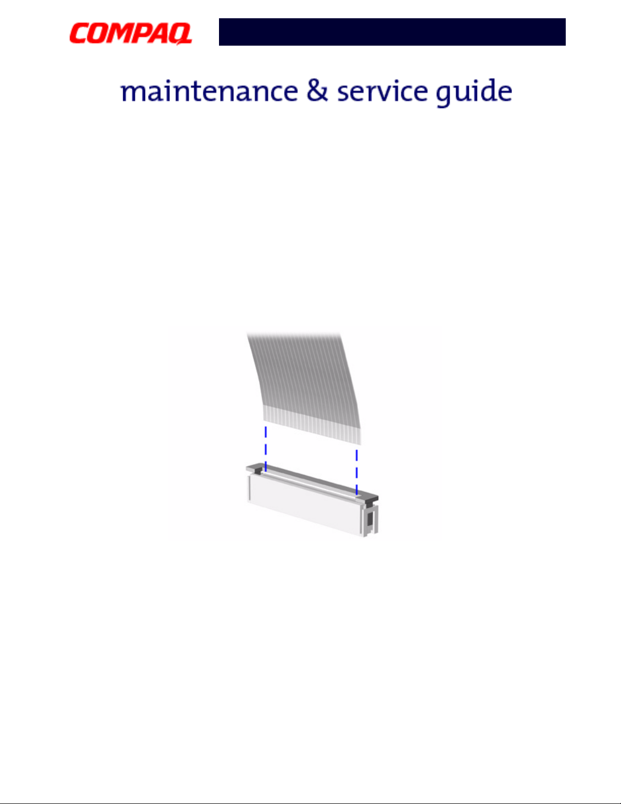
ZIF Connectors
The 1700LX Series Notebook uses zero insertion force (ZIF) connectors on the system
board.
CAUTION:
Ä
only the connector slide when removing or replacing a cable. Never pull or twist on
the cable while it is connected.
A ZIF connector and its attached cable can be easily damaged. Handle
To remove a cable from a ZIF connector, lift both corners of the ZIF connector and
simultaneously slide the cable out with constant light force.
CAUTION:
Ä
proper location during the reassembly process. Improper cable placement can
damage the Notebook.
P
RESARIO NOTEBOOK MAINTENANCE AND SERVICE GUIDE
When servicing the Notebook, ensure that cables are placed in their
1700XL S
ERIES
R
EMOVAL SEQUENCE
5
Page 7
Presario 1700 Series
Models: XL260, XL261, XL262, XL264, XL265, XL266, XL274, XL275, XL360, XL361,
XL362, XL363, XL364, XL365, XL366, XL367, XL368, XL369, XL370, XL371, XL372, XL373,
XL374, XL375, XL376, XL377, and XL378
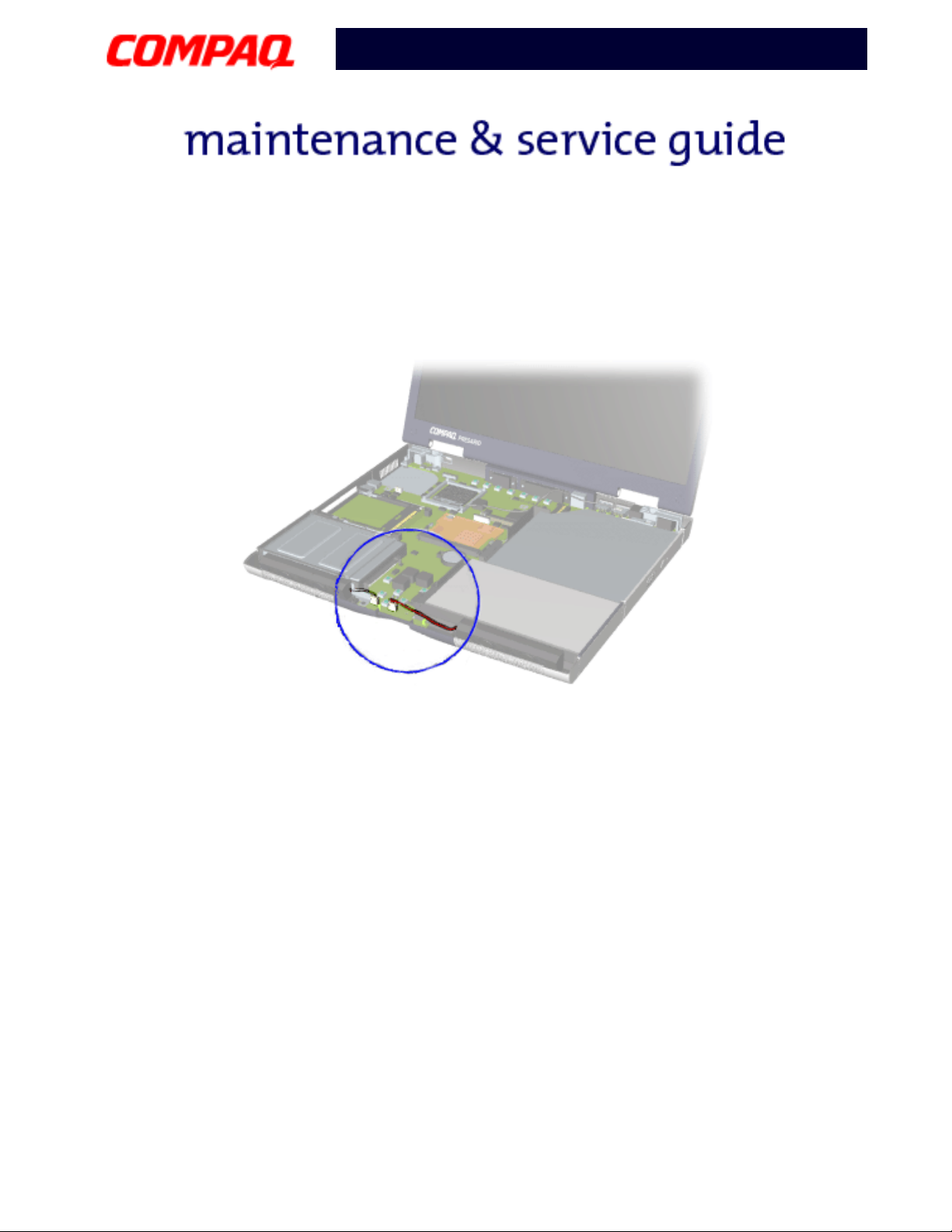
Speaker Assembly Cable
The cable position for the speaker assembly is shown below.
Ä
6 R
EMOVAL SEQUENCE
CAUTION:
proper location during the reassembly process. Improper cable placement can
damage the Notebook.
When servicing the Notebook, ensure that cables are placed in their
P
RESARIO NOTEBOOK MAINTENANCE AND SERVICE GUIDE
1700XL S
ERIES
Page 8

Presario 1700 Series
Models: XL260, XL261, XL262, XL264, XL265, XL266, XL274, XL275, XL360, XL361,
XL362, XL363, XL364, XL365, XL366, XL367, XL368, XL369, XL370, XL371, XL372, XL373,
XL374, XL375, XL376, XL377, and XL378
Preparing the Notebook for Disassembly
Before beginning Removal & Replacement Procedures, complete the following steps:
1. Disconnect AC power and any external devices.
2. Remove the QuikDock (pg 8
).
3. Remove the battery pack (pg 9
Important: The battery pack should be removed before performing any internal
maintenance on the Notebook.
WARNING: Metal objects can damage the battery pack as well as the battery
Å
contacts in the battery compartment. To prevent damage, do not allow metal
objects to touch the battery contacts. Place only the battery pack for the Compaq
Presario 1700 Series Portable Notebook into the battery compartment. Do not
force the battery pack into the bay if insertion is difficult.
CAUTION:
Ä
battery pack; this damages the pack, makes it unusable, and exposes potentially
harmful battery components. No field-serviceable parts are located inside the
battery pack.
Note: The Compaq Presario 1700 Series Portable Computers have several screws of
various sizes that are not interchangeable. During disassembly, place screws in
their correct location. During removal keep screws with their respective
subassembly to make reassembly easy.
Do not crush, puncture, or incinerate the battery pack. Do not open a
).
P
RESARIO NOTEBOOK MAINTENANCE AND SERVICE GUIDE
1700XL S
ERIES
R
EMOVAL SEQUENCE
7
Page 9
Presario 1700 Series
Models: XL260, XL261, XL262, XL264, XL265, XL266, XL274, XL275, XL360, XL361,
XL362, XL363, XL364, XL365, XL366, XL367, XL368, XL369, XL370, XL371, XL372, XL373,
XL374, XL375, XL376, XL377, and XL378
Removal Procedures
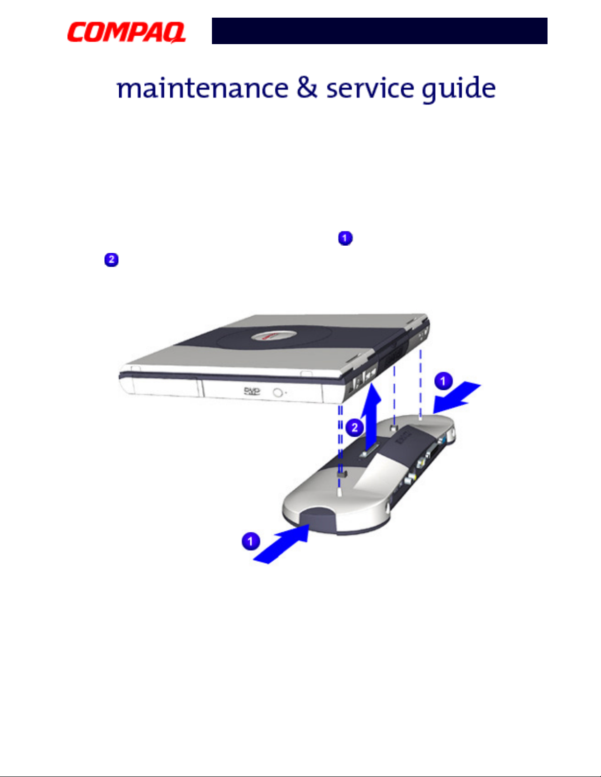
QuikDock
To disconnect the QuikDock from the unit, complete the following steps:
1. Simultaneously press the release mechanisms on both ends of the QuikDock.
2. Lift the unit off the alignment pins and the QuikDock connector.
To reconnect the QuikDock to the unit, reverse steps 1 and 2.
8 R
EMOVAL SEQUENCE
P
RESARIO NOTEBOOK MAINTENANCE AND SERVICE GUIDE
1700XL S
ERIES
Page 10
Presario 1700 Series
Models: XL260, XL261, XL262, XL264, XL265, XL266, XL274, XL275, XL360, XL361,
XL362, XL363, XL364, XL365, XL366, XL367, XL368, XL369, XL370, XL371, XL372, XL373,
XL374, XL375, XL376, XL377, and XL378
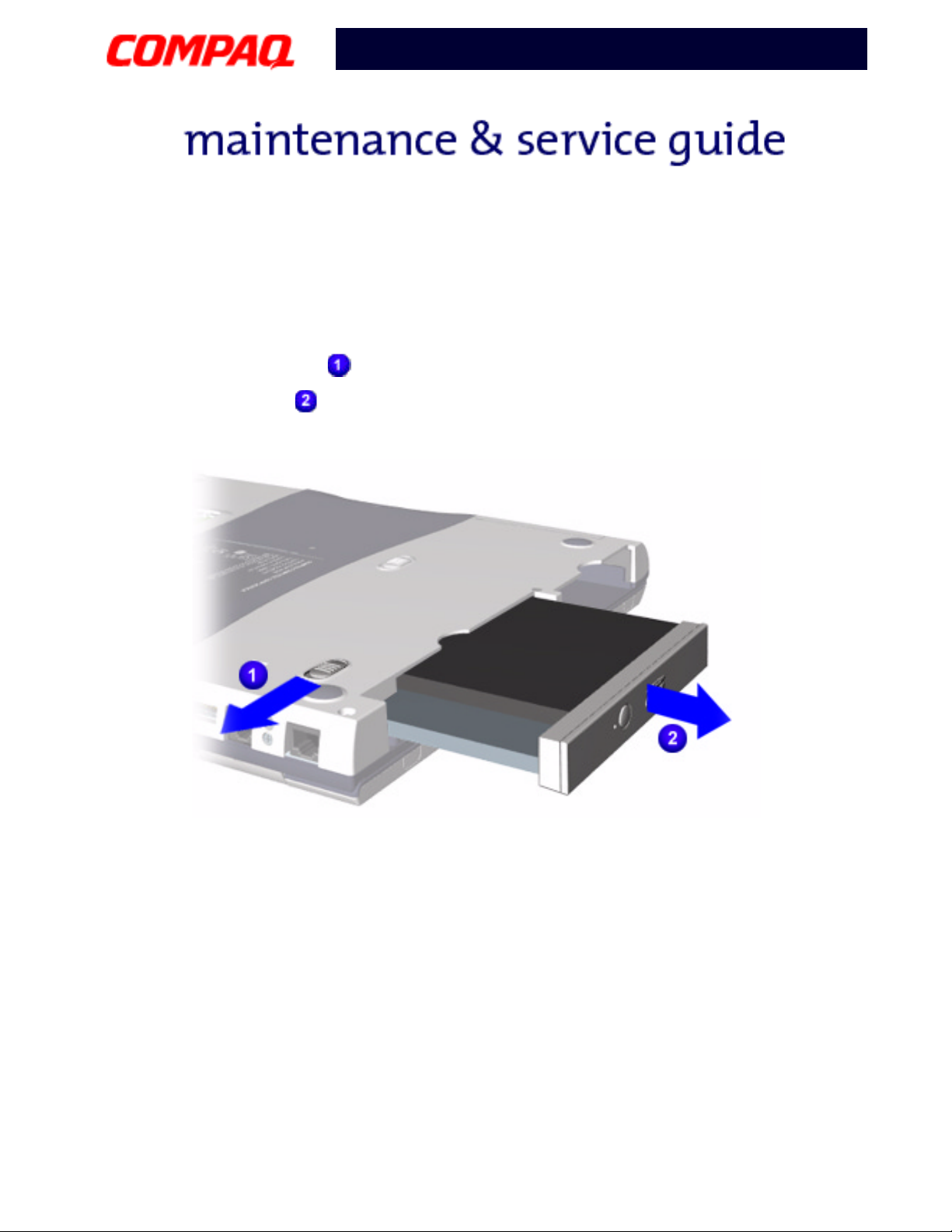
Battery
To remove the battery pack, complete the following steps:
1. Push the release latch at the bottom of the unit.
2. Pull the battery pack out.
To replace the battery pack, reverse steps 1 and 2.
Important: The battery pack should be removed before performing any internal
maintenance on the Notebook.
WARNING: Metal objects can damage the battery pack as well as the battery
Å
contacts in the battery compartment. To prevent damage, do not allow metal
objects to touch the battery contacts. Place only the battery pack for the Compaq
Presario 1700 Series Portable Notebook into the battery compartment. Do not
force the battery pack into the bay if insertion does not occur easily.
CAUTION:
Ä
battery pack; this action damages the pack, makes it unusable, and exposes
potentially harmful battery components. No field-serviceable parts are located
inside the battery pack.
P
RESARIO NOTEBOOK MAINTENANCE AND SERVICE GUIDE
Do not crush, puncture, or incinerate the battery pack. Do not open a
1700XL S
ERIES
R
EMOVAL SEQUENCE
9
Page 11
Presario 1700 Series
Models: XL260, XL261, XL262, XL264, XL265, XL266, XL274, XL275, XL360, XL361,
XL362, XL363, XL364, XL365, XL366, XL367, XL368, XL369, XL370, XL371, XL372, XL373,
XL374, XL375, XL376, XL377, and XL378
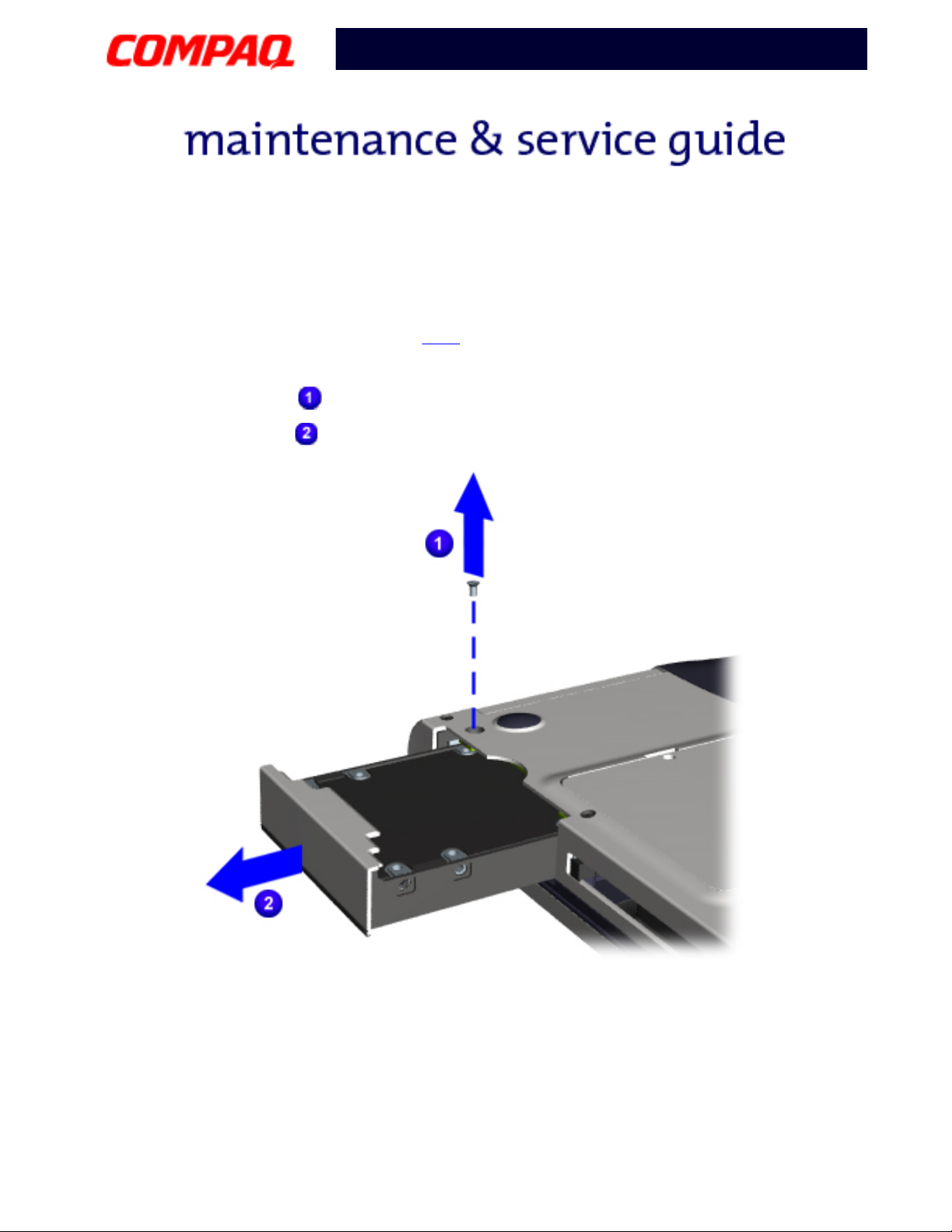
Hard Drive
To remove the hard drive, complete the following steps:
1. Prepare the unit for disassembly (pg 7
).
2. Turn the unit upside down.
3. Remove one screw from the bottom of the unit.
4. Pull the hard drive out.
10 R
EMOVAL SEQUENCE
P
RESARIO NOTEBOOK MAINTENANCE AND SERVICE GUIDE
1700XL S
ERIES
Page 12
Presario 1700 Series
Models: XL260, XL261, XL262, XL264, XL265, XL266, XL274, XL275, XL360, XL361,
XL362, XL363, XL364, XL365, XL366, XL367, XL368, XL369, XL370, XL371, XL372, XL373,
XL374, XL375, XL376, XL377, and XL378
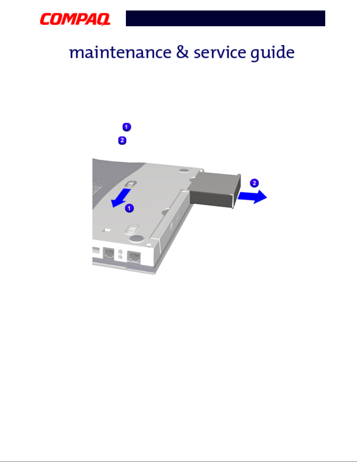
FutureBay
To remove the FutureBay, complete the following steps:
1. Turn the unit upside down.
2. Push the release lever back.
3. Pull the FutureBay device out.
™
P
RESARIO NOTEBOOK MAINTENANCE AND SERVICE GUIDE
1700XL S
ERIES
R
EMOVAL SEQUENCE
11
Page 13

Presario 1700 Series
Models: XL260, XL261, XL262, XL264, XL265, XL266, XL274, XL275, XL360, XL361,
XL362, XL363, XL364, XL365, XL366, XL367, XL368, XL369, XL370, XL371, XL372, XL373,
XL374, XL375, XL376, XL377, and XL378
LED Button Bezel
To remove the LED button bezel, complete the following steps:
1. Prepare the unit for disassembly (pg 7
).
2. Turn the unit upside down.
3. Remove two screws from each side of the Port Replicator connector.
4. Gently pry the ends of the LED button bezel upwards.
5. Lift the bezel off.
12 R
EMOVAL SEQUENCE
P
RESARIO NOTEBOOK MAINTENANCE AND SERVICE GUIDE
1700XL S
ERIES
Page 14

Presario 1700 Series
Models: XL260, XL261, XL262, XL264, XL265, XL266, XL274, XL275, XL360, XL361,
XL362, XL363, XL364, XL365, XL366, XL367, XL368, XL369, XL370, XL371, XL372, XL373,
XL374, XL375, XL376, XL377, and XL378
System Memory
To upgrade or replace the system memory, complete the following steps:
1. Prepare the unit for disassembly (pg 7
).
2. Turn the unit upside down.
3. Remove one screw on the memory compartment door.
4. Open the memory compartment door , release the locks on each sides of the
system memory, then remove the system memory.
To add memory modules, reverse steps 1 and 2 above.
P
RESARIO NOTEBOOK MAINTENANCE AND SERVICE GUIDE
1700XL S
ERIES
R
EMOVAL SEQUENCE
13
Page 15

Presario 1700 Series
Models: XL260, XL261, XL262, XL264, XL265, XL266, XL274, XL275, XL360, XL361,
XL362, XL363, XL364, XL365, XL366, XL367, XL368, XL369, XL370, XL371, XL372, XL373,
XL374, XL375, XL376, XL377, and XL378
Keyboard
To remove the keyboard, complete the following steps:
1. Prepare the unit for disassembly (pg 7
2. Remove the LED button bezel (pg 12
).
).
3. Lift the top of the keyboard, fold it forward, then lay it on top of the TouchPad.
14 R
EMOVAL SEQUENCE
P
RESARIO NOTEBOOK MAINTENANCE AND SERVICE GUIDE
1700XL S
ERIES
Page 16

Presario 1700 Series
Models: XL260, XL261, XL262, XL264, XL265, XL266, XL274, XL275, XL360, XL361,
XL362, XL363, XL364, XL365, XL366, XL367, XL368, XL369, XL370, XL371, XL372, XL373,
XL374, XL375, XL376, XL377, and XL378
Heatspreader
To remove the Heatspreader, complete the following steps:
1. Prepare the unit for disassembly (pg 7
2. Remove the LED button bezel (pg 12
3. Remove the keyboard (pg 14
).
).
).
4. Remove four screws and lift out the Heatspreader.
P
RESARIO NOTEBOOK MAINTENANCE AND SERVICE GUIDE
1700XL S
ERIES
R
EMOVAL SEQUENCE
15
Page 17
Presario 1700 Series
Models: XL260, XL261, XL262, XL264, XL265, XL266, XL274, XL275, XL360, XL361,
XL362, XL363, XL364, XL365, XL366, XL367, XL368, XL369, XL370, XL371, XL372, XL373,
XL374, XL375, XL376, XL377, and XL378
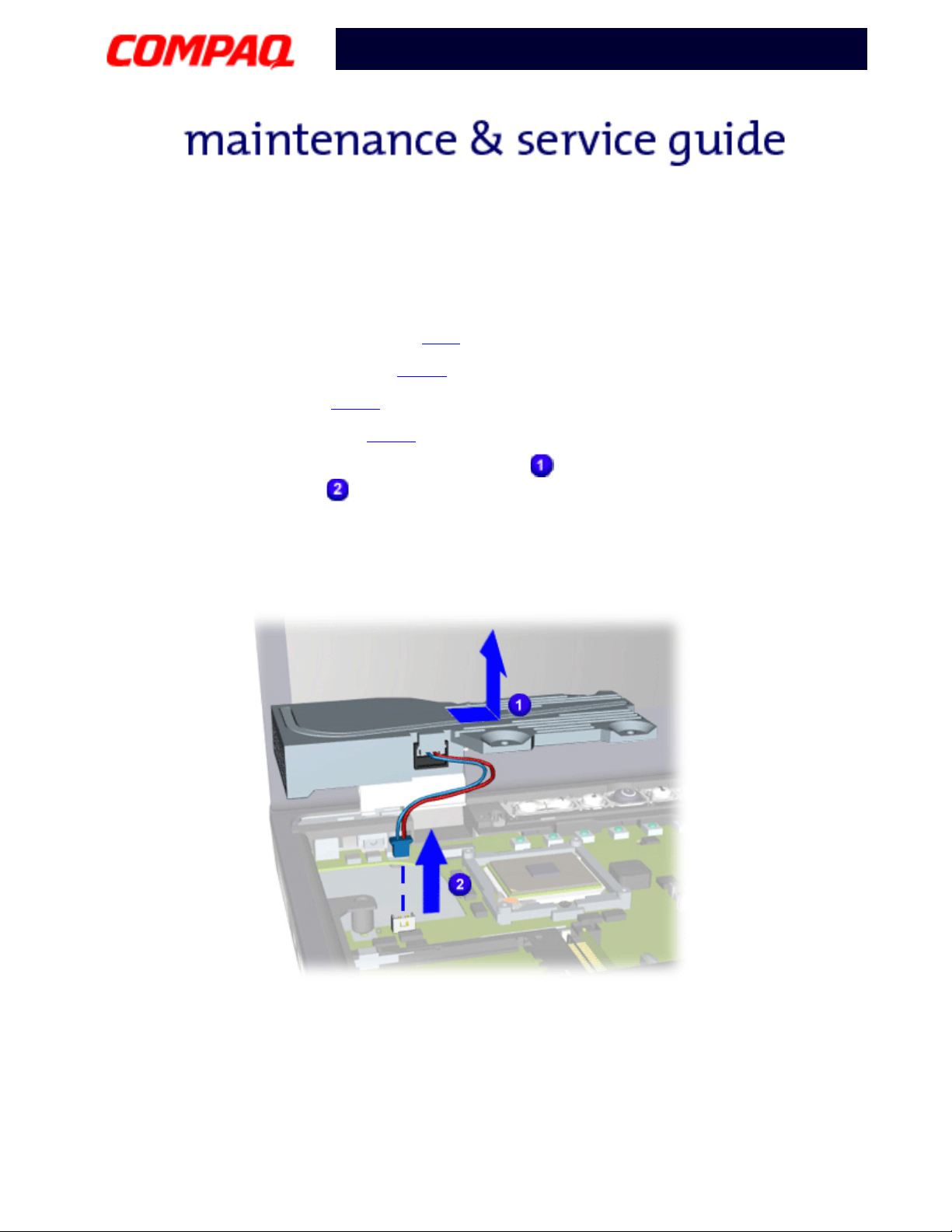
Heatsink Assembly (Fan Assembly)
To remove the Heatsink assembly, complete the following steps:
1. Prepare the unit for disassembly (pg 7
2. Remove the LED button bezel (pg 12
3. Remove the keyboard (pg 14
).
4. Remove the Heatspreader (pg 15
).
).
).
5. Lift up the right side of the Heatsink assembly , pull it to the right, then disconnect
the two-pin connector .
Note: The Heatsink assembly in the Notebook may differ from the one shown in the
illustration below.
16 R
EMOVAL SEQUENCE
P
RESARIO NOTEBOOK MAINTENANCE AND SERVICE GUIDE
1700XL S
ERIES
Page 18

Presario 1700 Series
Models: XL260, XL261, XL262, XL264, XL265, XL266, XL274, XL275, XL360, XL361,
XL362, XL363, XL364, XL365, XL366, XL367, XL368, XL369, XL370, XL371, XL372, XL373,
XL374, XL375, XL376, XL377, and XL378
Processor
To remove the processor, complete the following steps:
1. Prepare the unit for disassembly(pg 7
2. Remove the LED button bezel (pg 12
3. Remove the keyboard (pg 14
).
4. Remove the Heatspreader (pg 15
5. Remove the Heatsink assembly (pg 16
).
).
).
).
6. Turn screw counter-clockwise (1/2 turn only), then lift the processor and
remove it from the socket.
CAUTION:
Ä
socket, making it necessary to replace the system board.
If you turn the screw more than a half turn, you will damage the
P
RESARIO NOTEBOOK MAINTENANCE AND SERVICE GUIDE
1700XL S
ERIES
R
EMOVAL SEQUENCE
17
Page 19

Presario 1700 Series
Models: XL260, XL261, XL262, XL264, XL265, XL266, XL274, XL275, XL360, XL361,
XL362, XL363, XL364, XL365, XL366, XL367, XL368, XL369, XL370, XL371, XL372, XL373,
XL374, XL375, XL376, XL377, and XL378
To replace the processor, make sure that the processor’s pin 1 orientation is aligned
with the lower-left corner of the socket. Turn screw clockwise (1/2 turn only).
18 R
EMOVAL SEQUENCE
P
RESARIO NOTEBOOK MAINTENANCE AND SERVICE GUIDE
1700XL S
ERIES
Page 20

Presario 1700 Series
Models: XL260, XL261, XL262, XL264, XL265, XL266, XL274, XL275, XL360, XL361,
XL362, XL363, XL364, XL365, XL366, XL367, XL368, XL369, XL370, XL371, XL372, XL373,
XL374, XL375, XL376, XL377, and XL378
Keyboard Cable Connection
To remove the keyboard cable connection, complete the following steps:
1. Prepare the unit for disassembly (pg 7
2. Remove the LED button bezel (pg 12
3. Remove the keyboard (pg 14
).
4. Remove the Heatspreader (pg 15
5. Remove the Heatsink assembly (pg 16
).
).
).
).
6. Gently pry open the ZIF connector by carefully lifting on the left side, then the
right side, until you can lift no further.
7. Grasp the cable and GENTLY pull up from connector.
CAUTION:
Ä
damage, making it necessary to replace the system board.
Lifting the cable with too much force might result in system board
P
RESARIO NOTEBOOK MAINTENANCE AND SERVICE GUIDE
1700XL S
ERIES
R
EMOVAL SEQUENCE
19
Page 21

Presario 1700 Series
Models: XL260, XL261, XL262, XL264, XL265, XL266, XL274, XL275, XL360, XL361,
XL362, XL363, XL364, XL365, XL366, XL367, XL368, XL369, XL370, XL371, XL372, XL373,
XL374, XL375, XL376, XL377, and XL378
Modem/NIC Combo Card
Preparing for Modem/NIC Combo Card Removal
Prepare the unit for disassembly (pg 7), and remove the following before removing the
modem/NIC combo card:
1. Remove the LED button bezel (pg 12
2. Remove the keyboard (pg 14
).
3. Remove the Heatspreader (pg 15
4. Remove the Heatsink assembly (pg 16
5. Remove the keyboard cable connection (pg 19
Removing the Modem/NIC Combo Card
).
).
).
).
To remove the modem/NIC combo card, complete the following steps:
1. Gently pry open the ZIF connector by carefully lifting on the left side, then the
right side, until you can lift no further.
2. Grasp the cable and GENTLY pull up from connector.
CAUTION:
Ä
excessive force. You may otherwise have to replace the system board.
To prevent damage to the system board, do not pry and lift with
20 R
EMOVAL SEQUENCE
P
RESARIO NOTEBOOK MAINTENANCE AND SERVICE GUIDE
1700XL S
ERIES
Page 22

Presario 1700 Series
Models: XL260, XL261, XL262, XL264, XL265, XL266, XL274, XL275, XL360, XL361,
XL362, XL363, XL364, XL365, XL366, XL367, XL368, XL369, XL370, XL371, XL372, XL373,
XL374, XL375, XL376, XL377, and XL378
3. Pry latches on each side of the card outward.
4. Remove the two-pin connector on the left side of the card.
5. Grasp the upper-right hand corner of the Modem/NIC combo card, then lift it up and
pull it out .
To replace the card, remove the pin connector, insert a new card, then reconnect the pin.
P
RESARIO NOTEBOOK MAINTENANCE AND SERVICE GUIDE
1700XL S
ERIES
R
EMOVAL SEQUENCE
21
Page 23
Presario 1700 Series
Models: XL260, XL261, XL262, XL264, XL265, XL266, XL274, XL275, XL360, XL361,
XL362, XL363, XL364, XL365, XL366, XL367, XL368, XL369, XL370, XL371, XL372, XL373,
XL374, XL375, XL376, XL377, and XL378
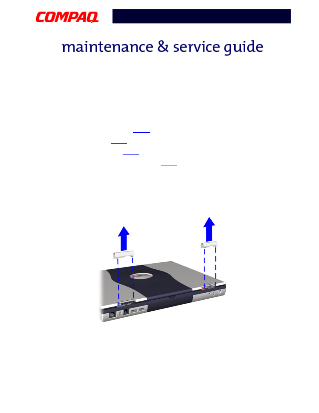
Display Panel
Preparing for the Display Panel Removal
Prepare the unit for disassembly (pg 7), and remove the following before removing the
display panel:
1. Remove the LED button bezel (pg 12
2. Remove the keyboard (pg 14
).
3. Remove the Heatspreader (pg 15
4. Remove the keyboard cable connection (pg 19
).
).
).
Removing the Display Panel
To remove the Display Panel, complete the following steps:
1. Close the Display Panel.
2. Remove each hinge cover by prying either side of the hinge cover up and lifting off.
22 R
EMOVAL SEQUENCE
P
RESARIO NOTEBOOK MAINTENANCE AND SERVICE GUIDE
1700XL S
ERIES
Page 24

Presario 1700 Series
Models: XL260, XL261, XL262, XL264, XL265, XL266, XL274, XL275, XL360, XL361,
XL362, XL363, XL364, XL365, XL366, XL367, XL368, XL369, XL370, XL371, XL372, XL373,
XL374, XL375, XL376, XL377, and XL378
3. Remove the screw on top of each hinge and the cable stabilizer clip from the
left-side hinge.
4. Remove two screws from the back of each hinge, then open the Display.
P
RESARIO NOTEBOOK MAINTENANCE AND SERVICE GUIDE
1700XL S
ERIES
R
EMOVAL SEQUENCE
23
Page 25

Presario 1700 Series
Models: XL260, XL261, XL262, XL264, XL265, XL266, XL274, XL275, XL360, XL361,
XL362, XL363, XL364, XL365, XL366, XL367, XL368, XL369, XL370, XL371, XL372, XL373,
XL374, XL375, XL376, XL377, and XL378
5. Remove the back light cable by carefully lifting it from the socket.
6. Remove the Display cable by prying on the left and right sides of the cable
connector until it is detached.
24 R
EMOVAL SEQUENCE
P
RESARIO NOTEBOOK MAINTENANCE AND SERVICE GUIDE
1700XL S
ERIES
Page 26

Presario 1700 Series
Models: XL260, XL261, XL262, XL264, XL265, XL266, XL274, XL275, XL360, XL361,
XL362, XL363, XL364, XL365, XL366, XL367, XL368, XL369, XL370, XL371, XL372, XL373,
XL374, XL375, XL376, XL377, and XL378
7. Grasp the panel assembly and lift up to remove it.
P
RESARIO NOTEBOOK MAINTENANCE AND SERVICE GUIDE
1700XL S
ERIES
R
EMOVAL SEQUENCE
25
Page 27

Presario 1700 Series
Models: XL260, XL261, XL262, XL264, XL265, XL266, XL274, XL275, XL360, XL361,
XL362, XL363, XL364, XL365, XL366, XL367, XL368, XL369, XL370, XL371, XL372, XL373,
XL374, XL375, XL376, XL377, and XL378
CPU Top Cover with TouchPad/Palmrest
Preparing for CPU Top Cover with TouchPad/Palmrest Removal
Prepare the unit for disassembly (pg 7), and remove the following before removing the CPU
Top Co ve r w it h To uc h Pa d/ Pal mr es t:
1. Remove the hard drive (pg 10
2. Remove the FutureBay (pg 11
3. Remove the LED button bezel (pg 12
4. Remove the keyboard (pg 14
5. Remove the Heatspreader (pg 15
6. Remove the Heatsink assembly (pg 16
).
).
).
).
).
).
7. Remove the keyboard cable connection (pg 19
8. Remove the Display Panel (pg 22
).
).
26 R
EMOVAL SEQUENCE
P
RESARIO NOTEBOOK MAINTENANCE AND SERVICE GUIDE
1700XL S
ERIES
Page 28

Presario 1700 Series
Models: XL260, XL261, XL262, XL264, XL265, XL266, XL274, XL275, XL360, XL361,
XL362, XL363, XL364, XL365, XL366, XL367, XL368, XL369, XL370, XL371, XL372, XL373,
XL374, XL375, XL376, XL377, and XL378
Removing the CPU Top Cover with TouchPad/Palmrest
To remove the CPU Top Cover with TouchPad/Palmrest, complete the following steps:
1. Turn the unit upside down.
2. Remove seven screws from the underside of the unit.
P
RESARIO NOTEBOOK MAINTENANCE AND SERVICE GUIDE
1700XL S
ERIES
R
EMOVAL SEQUENCE
27
Page 29

Presario 1700 Series
Models: XL260, XL261, XL262, XL264, XL265, XL266, XL274, XL275, XL360, XL361,
XL362, XL363, XL364, XL365, XL366, XL367, XL368, XL369, XL370, XL371, XL372, XL373,
XL374, XL375, XL376, XL377, and XL378
3. Turn the unit right-side up and remove four screws.
4. Unplug the Zif Connector
for the TouchPad.
5. Lift and remove the CPU Top Cover with TouchPad/Palmrest.
28 R
EMOVAL SEQUENCE
P
RESARIO NOTEBOOK MAINTENANCE AND SERVICE GUIDE
1700XL S
ERIES
Page 30

Presario 1700 Series
Models: XL260, XL261, XL262, XL264, XL265, XL266, XL274, XL275, XL360, XL361,
XL362, XL363, XL364, XL365, XL366, XL367, XL368, XL369, XL370, XL371, XL372, XL373,
XL374, XL375, XL376, XL377, and XL378
Sub IO Board
Preparing for Sub IO Board Removal
Prepare the unit for disassembly (pg 7), and remove the following before removing the
Sub IO Board:
1. Remove the hard drive (pg 10
2. Remove FutureBay (pg 11
3. Remove the LED button bezel (pg 12
4. Remove the keyboard (pg 14
5. Remove the Heatspreader (pg 15
6. Remove the Heatsink assembly (pg 16
7. Remove the keyboard cable connection (pg 19
8. Remove the Display Panel (pg 22
).
).
).
).
).
).
).
).
9. Remove the CPU Top Cover with TouchPad/Palmrest (pg 26
).
P
RESARIO NOTEBOOK MAINTENANCE AND SERVICE GUIDE
1700XL S
ERIES
R
EMOVAL SEQUENCE
29
Page 31

Presario 1700 Series
Models: XL260, XL261, XL262, XL264, XL265, XL266, XL274, XL275, XL360, XL361,
XL362, XL363, XL364, XL365, XL366, XL367, XL368, XL369, XL370, XL371, XL372, XL373,
XL374, XL375, XL376, XL377, and XL378
Removing the Sub IO Board
To remove the Sub IO board, complete the following steps:
1. Remove two screws from the right hinge support bracket and lift the bracket up to
remove it.
30 R
EMOVAL SEQUENCE
P
RESARIO NOTEBOOK MAINTENANCE AND SERVICE GUIDE
1700XL S
ERIES
Page 32

Presario 1700 Series
Models: XL260, XL261, XL262, XL264, XL265, XL266, XL274, XL275, XL360, XL361,
XL362, XL363, XL364, XL365, XL366, XL367, XL368, XL369, XL370, XL371, XL372, XL373,
XL374, XL375, XL376, XL377, and XL378
2. Grasp the right-hand corner of the board and lift it up slightly.
3. Pull the board to the right until the IO connector is disconnected from the system
board.
P
RESARIO NOTEBOOK MAINTENANCE AND SERVICE GUIDE
1700XL S
ERIES
R
EMOVAL SEQUENCE
31
Page 33

Presario 1700 Series
Models: XL260, XL261, XL262, XL264, XL265, XL266, XL274, XL275, XL360, XL361,
XL362, XL363, XL364, XL365, XL366, XL367, XL368, XL369, XL370, XL371, XL372, XL373,
XL374, XL375, XL376, XL377, and XL378
System Board
Preparing for System Board Removal
Prepare the unit for disassembly (pg 7), and remove the following before removing the
system board:
1. Remove the hard drive (pg 10
2. Remove the FutureBay (pg 11
3. Remove the LED button bezel (pg 12
4. Remove the keyboard (pg 14
5. Remove the Heatspreader (pg 15
6. Remove the Heatsink assembly (pg 16
7. Remove the Display Panel (pg 22
).
).
).
).
).
).
).
8. Remove the CPU Top Cover with TouchPad/Palmrest (pg 26
9. Remove the processor (pg 17
10. Remove the keyboard cable connection (pg 19
11. Remove the modem or NIC combo card (pg 20
12. Remove the Sub IO Board (pg 29
).
).
).
).
).
32 R
EMOVAL SEQUENCE
P
RESARIO NOTEBOOK MAINTENANCE AND SERVICE GUIDE
1700XL S
ERIES
Page 34

Presario 1700 Series
Models: XL260, XL261, XL262, XL264, XL265, XL266, XL274, XL275, XL360, XL361,
XL362, XL363, XL364, XL365, XL366, XL367, XL368, XL369, XL370, XL371, XL372, XL373,
XL374, XL375, XL376, XL377, and XL378
Removing the System Board
To remove the system board, complete the following steps:
1. Remove one screw by the CMOS Battery .
2. Remove two screws from the left hinge bracket and lift up to remove
the bracket .
P
RESARIO NOTEBOOK MAINTENANCE AND SERVICE GUIDE
1700XL S
ERIES
R
EMOVAL SEQUENCE
33
Page 35

Presario 1700 Series
Models: XL260, XL261, XL262, XL264, XL265, XL266, XL274, XL275, XL360, XL361,
XL362, XL363, XL364, XL365, XL366, XL367, XL368, XL369, XL370, XL371, XL372, XL373,
XL374, XL375, XL376, XL377, and XL378
3. Remove two screws on the hard drive frame, and lift the frame up to remove it.
4. Unplug the two speaker cables.
34 R
EMOVAL SEQUENCE
P
RESARIO NOTEBOOK MAINTENANCE AND SERVICE GUIDE
1700XL S
ERIES
Page 36

Presario 1700 Series
Models: XL260, XL261, XL262, XL264, XL265, XL266, XL274, XL275, XL360, XL361,
XL362, XL363, XL364, XL365, XL366, XL367, XL368, XL369, XL370, XL371, XL372, XL373,
XL374, XL375, XL376, XL377, and XL378
5. Press the button on the side of the card-bus bezel to release the button. Press the
button again to eject the card in the card-bus bezel. Remove the card.
6. Start lifting the board at the lower right corner , pry the frame slightly
outward near the two audio jacks to release the jacks, then lift the system board out.
P
RESARIO NOTEBOOK MAINTENANCE AND SERVICE GUIDE
1700XL S
ERIES
R
EMOVAL SEQUENCE
35
Page 37

Presario 1700 Series
Models: XL260, XL261, XL262, XL264, XL265, XL266, XL274, XL275, XL360, XL361,
XL362, XL363, XL364, XL365, XL366, XL367, XL368, XL369, XL370, XL371, XL372, XL373,
XL374, XL375, XL376, XL377, and XL378
Left and Right Speaker Assembly
To remove the left and right speaker assembly, prepare the unit for disassembly
) and complete the following steps:
(pg 7
1. Remove the hard drive (pg 10
2. Remove the FutureBay (pg 11
3. Remove the LED button bezel (pg 12
4. Remove the keyboard (pg 14
5. Remove the Heatspreader (pg 15
6. Remove the Heatsink assembly (pg 16
7. Remove the keyboard cable connection (pg 19
8. Remove the Display Panel (pg 22
9. Remove the CPU Top Cover with TouchPad/Palmrest (pg 26
).
).
).
).
).
).
).
).
).
10. Remove the two screws connecting the speaker assembly to the chassis.
36 R
EMOVAL SEQUENCE
P
RESARIO NOTEBOOK MAINTENANCE AND SERVICE GUIDE
1700XL S
ERIES
 Loading...