

Page 1
S
S
S
C
C
C
P
P
P
r
r
e
e
p
p
r
r
o
o
c
c
o
o
n
n
t
t
r
r
o
o
f
l
f
l
o
o
r
r
H
H
P
P
M
M
a
a
n
n
u
u
a
a
l
l
l
a
u
n
a
M
P
H
r
o
f
l
o
r
t
n
o
c
o
r
p
e
r
Manual- / Software Version: 4.5
Revision: 27.01.2009
Software and hardware specifications as well as companies’ respective brands used in this manual are
generally subject to protection by trademark, label or patent.
SCP Software GmbH
Dresdener Straße 3 D-52068 Aachen
Tel: (0241) 9 68 30 - 0 Fax: (0241) 9 68 30 – 10
http://www.scp.de Email: info@scp.de
© 1996 – 2008 SCP Software GmbH
Portions Copyright (C) 2001 artofcode LLC. All rights reserved.
Portions Copyright (C) 1996, 2001 Artifex Software Inc. All rights reserved.
Portions Copyright (C) 1988, 2000 Aladdin Enterprises. All rights reserved
This software is based in part on the work of the independent JPEG Group.
Portions Copyright (C) 1998 Soft Horizons. All rights reserved.
LuraDocument-Technologie Copyright (C) 2000 LuraTech GmbH
Portions Copyright (C) 2000 LuraDocument
Portions Copyright (c) 1999-2000, Image Power, Inc. and the University of British
Portions Columbia, Canada.
Portions Copyright (c) 2001 Michael David Adams. All rights reserved.
reprocontrol contains software licensed from Autodesk, Inc. Copyright 2005, Autodesk, Inc. All Rights Reserved. Autodesk and DWF are
trademarks or registered trademarks of Autodesk, Inc.
Please note that the usage of SSl may be forbidden in your country. If so please deactivate this function by
deleting the files ssleay32.dll und libeay32.dll. in your installation folder.
Depending on your license, not all options may be available.
1
Page 2

Content
INTRODUCTION / REQUIREMENTS .......................................................................................................7
SYSTEM REQUIREMENTS.................................................................................................................................. 7
HARDWARE REQUIREMENTS ............................................................................................................................. 7
OPERATING SYSTEMS..................................................................................................................................... 7
INSTALLATION....................................................................................................................................8
PRINTER INSTALLATION .................................................................................................................................. 8
INSTALLATION OF THE HARDLOCK..................................................................................................................... 8
INSTALLATION OF THE PROGRAM....................................................................................................................... 9
REPROCONTROL.SERVER
REPROCONTROL.CLIENT
REPROCONTROL.PRINT
LOGIN ..............................................................................................................................................12
KEYCODE ENTRY...............................................................................................................................13
HARDWARE CONFIGURATION............................................................................................................14
PRINTERS / QUEUES .................................................................................................................................... 14
PRINTER CONFIGURATION......................................................................................................................... 14
DELETE PRINTER .................................................................................................................................... 15
THE SINGLE CONFIGURATION DIALOGS ......................................................................................................... 15
THE CONFIGURATION WIZARD ....................................................................................................................... 16
NAME / CONNECTION ............................................................................................................................. 16
PRINTER NAME .................................................................................................................................. 16
TCP/IP .......................................................................................................................................... 16
WINDOWS SPOOLING........................................................................................................................... 16
PLACEMENT .......................................................................................................................................... 17
DEFINE OUTPUT PAPER SIZE ................................................................................................................... 17
ROTATE .......................................................................................................................................... 18
ALIGNMENT ...................................................................................................................................... 18
ROLLWIDTH TOLERANCE....................................................................................................................... 18
TECHNICAL LABEL .................................................................................................................................. 19
CONFIGURATION / LOADED CONSUMABLES ................................................................................................... 20
DEFINE MEDIALIST .................................................................................................................................. 20
DEFAULT SETTINGS FOR PRINT OPTIONS ....................................................................................................... 21
CALIBRATION ........................................................................................................................................ 23
CALIBRATION FOR RIP......................................................................................................................... 23
OPTIONS IN THE CALIBRATION DIALOG .................................................................................................... 24
CREATE QUEUE .......................................................................................................................................... 27
TAB GENERAL ....................................................................................................................................... 27
QUEUE ............................................................................................................................................ 27
PRINTER .......................................................................................................................................... 27
MEDIUM .......................................................................................................................................... 28
SET PRINT SIZE.................................................................................................................................. 28
USE PRINTER DEFAULT SETTINGS............................................................................................................ 28
........................................................................................................................... 10
............................................................................................................................ 10
............................................................................................................................. 10
2
Page 3

PICTURE EDIT SETTINGS....................................................................................................................... 28
TAB OUTPUT OPTIONS ............................................................................................................................ 29
COPIES............................................................................................................................................ 29
SET OUTPUT SIZE............................................................................................................................... 29
TAB QUEUE .......................................................................................................................................... 30
QUEUE DESCRIPTION ........................................................................................................................... 30
PRIORITY ......................................................................................................................................... 30
DE-/ACTIVATION OF THE QUEUE........................................................................................................... 30
SET TIME FRAME FOR QUEUE ACTIVITY .................................................................................................... 30
SET USER RIGHTS TO CHANGE QUEUE ...................................................................................................... 31
LISTEN TO LPR.................................................................................................................................. 31
LISTEN TO RAW PORT .......................................................................................................................... 31
TAB HPGL........................................................................................................................................... 32
CREATE PRINTER CLUSTER ............................................................................................................................ 33
LOAD SHARING...................................................................................................................................... 33
SIMULATION OF A MULTIROLL PRINTER.......................................................................................................... 33
COST OPTIMIZING................................................................................................................................... 33
TAB GENERAL ....................................................................................................................................... 34
CLUSTER.......................................................................................................................................... 34
ARTICLE CODE .................................................................................................................................. 34
PRINTER .......................................................................................................................................... 34
MEDIUM .......................................................................................................................................... 34
MAX. PRINT SIZE................................................................................................................................ 35
USE PRINTER DEFAULT SETTINGS............................................................................................................ 35
PICTURE EDIT SETTINGS....................................................................................................................... 35
TAB OUTPUT OPTIONS ............................................................................................................................ 36
TAB QUEUE .......................................................................................................................................... 36
DISTRIBUTE JOBS AMONG SIMILAR PRINTERS OF THE CLUSTER .......................................................................... 36
ALLOW MONOCHROME PRINTS ON COLOR PRINTERS ..................................................................................... 36
WAIT FOR BEST FITTING PRINTER WHEN BUSY.............................................................................................. 36
TAB HPGL........................................................................................................................................... 36
PREFERENCES....................................................................................................................................37
TAB GENERAL............................................................................................................................... ............. 37
PAPER FORMAT...................................................................................................................................... 37
CREATE USER-DEFINED FORMATS............................................................................................................ 37
UNIT................................................................................................................................................... 38
SIMPLE FILTER EDITOR BY DEFAULT FOR RIP................................................................................................... 38
USE SCREEN ICC PROFILE......................................................................................................................... 38
SHOW WARNING FOR DEMO VERSION ............................................................................................................ 38
SHOW WARNING WHEN CONFIGURATION CHANGES ........................................................................................... 38
SHOW WARNING WHEN UNSAVED CHANGES WILL BE DELETED ............................................................................... 38
START NEW JOB AFTER SUBMIT.................................................................................................................... 38
JOB NUMBER IN PRINTER DISPLAY................................................................................................................. 38
USE COMPRESSED TRANSFER ...................................................................................................................... 39
MENU BAR OPTIONS..........................................................................................................................40
3
Page 4

FILE ........................................................................................................................................................ 40
FILES TO PRINT SELECTION........................................................................................................................ 40
EXIT ................................................................................................................................................... 40
CONFIGURATION ........................................................................................................................................ 41
PRINTERS/QUEUES.................................................................................................................................. 41
CALIBRATION ........................................................................................................................................ 41
PREFERENCES ........................................................................................................................................ 41
SHOW FILTERS ....................................................................................................................................... 42
LOAD PRESET ........................................................................................................................................ 42
SAVE PRESET ......................................................................................................................................... 42
SET AS DEFAULT..................................................................................................................................... 42
APPLY SETTINGS GLOBALLY....................................................................................................................... 42
LOG IN … ............................................................................................................................................ 42
CHANGE PASSWORD ................................................................................................................................ 43
VIEW....................................................................................................................................................... 44
PREVIEW .............................................................................................................................................. 44
SHOW BUTTON CAPTION........................................................................................................................... 44
SHOW PREFLIGHT.................................................................................................................................... 44
SHOW FILE PATH .................................................................................................................................... 44
EDIT ....................................................................................................................................................... 45
UP ..................................................................................................................................................... 45
DOWN................................................................................................................................................. 45
ACTIVATE ALL ....................................................................................................................................... 45
DEACTIVATE ALL .................................................................................................................................... 45
SWITCH ACTIVE...................................................................................................................................... 45
PREVIEW .............................................................................................................................................. 46
ACTIONS.................................................................................................................................................. 46
SUBMIT................................................................................................................................................ 46
INFO ....................................................................................................................................................... 46
ABOUT ................................................................................................................................................ 46
JOB MONITOR ....................................................................................................................................... 46
COSTTRACKER....................................................................................................................................... 46
HELP .................................................................................................................................................. 47
REPROCONTROL.CLIENT MAIN APPLICATIONS....................................................................................48
BASICS .................................................................................................................................................... 48
FEATURES OF THE TOOLBAR........................................................................................................................... 49
ADD FILE(S).......................................................................................................................................... 49
DELETE................................................................................................................................................ 49
LOAD JOB............................................................................................................................................. 49
INSERT JOB ........................................................................................................................................... 49
SAVE JOB ............................................................................................................................................. 49
START NEW JOB...................................................................................................................................... 50
RELOAD JOB.......................................................................................................................................... 50
PREVIEW................................................................................................................................................... 51
RIP PREVIEW ......................................................................................................................................... 52
SELECT AN AREA .................................................................................................................................... 52
4
Page 5

EDIT AOI ........................................................................................................................................ 52
RESET AOI SETTING................................................................................................................................ 52
APPLY FILTERING.................................................................................................................................... 52
SHOW GAMUT WARNING .......................................................................................................................... 53
SOFTPROOF .......................................................................................................................................... 53
EDIT IMAGES AND OUTPUT ............................................................................................................................ 54
TAB GENERAL ....................................................................................................................................... 54
FILE................................................................................................................................................ 54
USE COLOR MANAGEMENT ................................................................................................................... 54
ORIGINAL SIZE .................................................................................................................................. 55
PRINT SIZE ....................................................................................................................................... 55
COPIES............................................................................................................................................ 55
PRINTER .......................................................................................................................................... 55
MEDIUM .......................................................................................................................................... 56
PRINT MODE ............................................................................................................................... ..... 56
FILTER ............................................................................................................................................ 56
BRIGHTNESS ..................................................................................................................................... 56
TAB HPGL........................................................................................................................................... 57
PEN SETTINGS ................................................................................................................................... 57
USER PEN SETTINGS............................................................................................................................ 58
CHANGE PEN COLOR .......................................................................................................................... 58
SAVE / LOAD PEN PARAMETERS ............................................................................................................. 58
PREVIEW .............................................................................................................................................. 58
FILTER EDITOR..................................................................................................................................59
FUNCTIONS AND STRUCTURE OF THE FILTER EDITOR............................................................................................. 59
PREVIEW OF THE FILTER EDITOR.................................................................................................................. 60
HISTOGRAM.......................................................................................................................................... 61
TAB BLACK AND WHITE POINT (COLOR MODE WITHOUT COLOR MANAGEMENT)...................................................... 62
SETTING THE BLACK AND WHITE POINTS WITH THE PICKERS ........................................................................... 62
BLACK POINT.................................................................................................................................... 62
WHITE POINT.................................................................................................................................... 63
CONTRAST ....................................................................................................................................... 63
TEXT/BACKGROUND........................................................................................................................... 63
TAB POSTPROCESSING (BLACK & WHITE MODE).............................................................................................. 64
DESPECKLING .................................................................................................................................... 64
HOLE FILLING ................................................................................................................................... 65
INVERTED......................................................................................................................................... 65
TAB GAMMA CORRECTION (COLOR MODE WITHOUT COLOR MANAGEMENT) .......................................................... 66
GAMMA (GAMMA SLIDERS) ................................................................................................................... 66
TAB ENHANCEMENT (COLOR MODE WITH COLOR MANAGEMENT) ........................................................................ 67
SETTING THE BLACK AND WHITE POINTS WITH THE PICKERS ........................................................................... 67
SLIDERS FOR THE WHITE POINT .............................................................................................................. 67
TAB SPECIAL FILTER (ALL MODES
NONE ............................................................................................................................................. 68
ADAPTIVE SHARPNESS ......................................................................................................................... 68
SMOOTH ......................................................................................................................................... 70
EXCEPT OF
BLACK & WHITE MODE) ................................................................... 68
5
Page 6

SHARP ............................................................................................................................................ 70
FILTER RADIUS [µM]............................................................................................................................ 70
TAB COLOR ADJUST (COLOR MODE WITH COLOR MANAGEMENT)........................................................................ 71
TAB COLOR EXCHANGE (COLOR MODE WITH COLOR MANAGEMENT).................................................................... 72
LAB COLOR SPACE ............................................................................................................................. 73
REPROCONTROL.WINDRIVER .............................................................................................................74
WINDRIVER SETTINGS .................................................................................................................................. 75
TAB SETTINGS ....................................................................................................................................... 75
USE LAST SETTINGS............................................................................................................................. 75
SHOW FINISH MESSAGE......................................................................................................................... 75
TAB LOG ............................................................................................................................... .............. 75
USING THE WINDRIVER ................................................................................................................................ 76
REPROCONTROL.MONITOR ...............................................................................................................77
TAB JOBS ................................................................................................................................................. 77
BUTTON COMMANDS ............................................................................................................................... 78
START ............................................................................................................................................ 78
PAUSE............................................................................................................................................. 78
EXPRESS .......................................................................................................................................... 78
DETAILS .......................................................................................................................................... 78
DELETE ........................................................................................................................................... 78
TAB PRINTERS/QUEUES ................................................................................................................................ 79
TAB CONNECTION ...................................................................................................................................... 79
MENU OPTIONS ......................................................................................................................................... 80
TAB CONFIGURATION .................................................................................................................................. 81
KEYCODE ............................................................................................................................... .............. 81
JOB DATABASE....................................................................................................................................... 81
HIDE DONE JOBS AFTER ........................................................................................................................ 81
DELETE DONE JOB FILES AFTER ............................................................................................................... 81
REMOVE DONE JOB RECORDS AFTER ......................................................................................................... 81
UNIT................................................................................................................................................... 82
COSTTRACKER..................................................................................................................................83
SUMMARY................................................................................................................................................. 83
DETAILS................................................................................................................................................... 84
PRICES FOR CONSUMABLES (TAB PRICES FOR MEDIA & TAB PRICES FOR INKS).............................................................. 85
PREFERENCES............................................................................................................................................. 86
EXPORT ................................................................................................................................................... 86
CALIBRATION OF THE COSTTRACKER ................................................................................................................ 87
REPROCONTROL.BACKUP ..................................................................................................................88
6
Page 7

Introduction / Requirements
System Requirements
We recommend a PC with:
3,0 GHz clock speed
at least 1 GB RAM
Harddisk of 100 GB at least
DVD-ROM
USB-connection (to connect the hardlock)
19“- screen
Windows Vista or XP
Hardware Requirements
For connecting your printer, you may need:
a USB Port,
a Firewire connection or
a TCP/IP connection.
Operating Systems
We recommend Windows Vista or Windows XP but Windows NT2000 is also compatible. Please take notice of your
hardware specifications as compatibility with certain operating systems might be restricted.
7
Page 8

Installation
Printer installation
Please make sure that all your printers drivers are installed correctly to your system or you have full network access
to them. Please follow the installation manuals of your printers.
The printer connected to your system may require the installation of additional drivers.
You may also need additional drivers with devices that are connected via USB or FireWire. These drivers should
also have been delivered with the devices. Please consult the manufacturer’s instructions.
You will often have to install the drivers delivered with your devices before connecting your printer to the PC.
Installation of the Hardlock
Do not plug in the dongle during the software installation!
You may put it on upon or after reprocontrol for HP software installation: the hardware drivers are installed
and applied automatically in both cases.
We recommend plugging in the dongle upon software installation. By doing so, you may easily switch to the
full version of reprocontrol for HP when entering the correct keycode (see §
If you plugged in the dongle after software installation, you have to restart the system after entering the correct
keycode. Otherwise, the program will remain in the demo mode.
KEYCO DE ENTRY).
8
Page 9
Installation of the Program
Insert the CD into the CD-ROM drive and exit all applications. If Autostart is activated in your operating system, the
installation program is started automatically. If this function is deactivated, start the file S
installation CD.
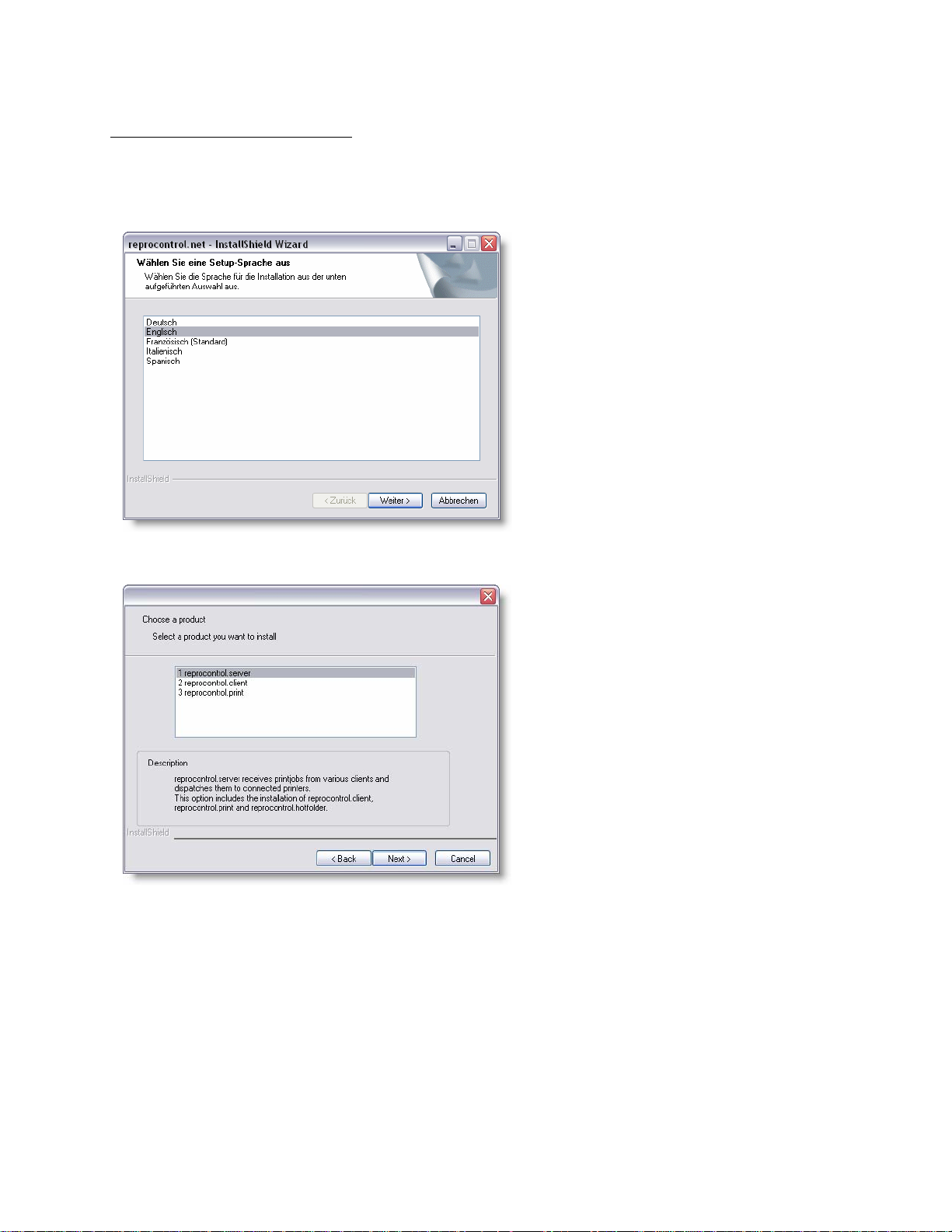
Select the language you want to work in.
A setup dialog appears on screen, followed by the
welcome dialog. Click on the NEXT button.
Select one of the following products which you want to install:
ETUP.EXE from the
9
Page 10
reprocontrol.server
This will install reprocontrol.server, reprocontrol.print and reprocontrol.client. Every network computer having
installed reprocontrol.server can be a server for all print jobs sent by reprocontrol.clients.
Reprocontrol.client is needed to configure your reprocontrol.server and to work with images. If you run a local
reprocontrol.server while using reprocontrol.client, you will be automatically identified as an administrative
reprocontrol.client.
Reprocontrol.print is a separate RIP-processing service. It is not necessary to use the same reprocontrol.print
installed with reprocontrol.server as long as at least one PC provides reprocontrol.print to the network.
reprocontrol.client
Choosing this option will only install the client version of reprocontrol for HP. Thus, reprocontrol.clients need
network access to computers providing a reprocontrol.server.
Reprocontrol.client is the basic program to work with images and to print them. Additionally, it is needed to
customize your reprocontrol.server to your demands.
reprocontrol.print
Only reprocontrol.print is installed on your system after selecting this option. Reprocontrol.print is a subsystem
for calculating RIP-processes. It is an essential part of the reprocontrol network and has to be provided to the
network at least by one PC.
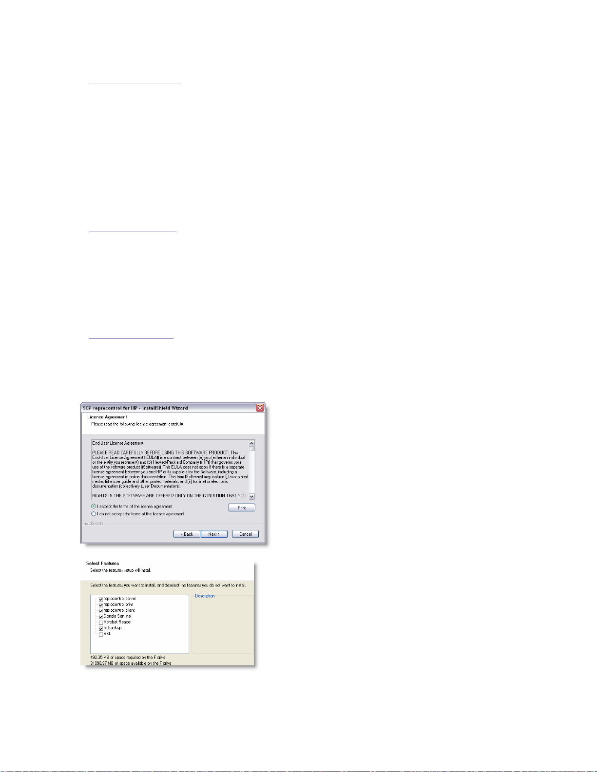
After selecting the desired program, you then have to accept
the license agreement by selecting the corresponding radio
button option in order to continue the installation. To get a print
out version of the same license agreement as displayed, click
RINT button.
the P
If you do not accept the terms of the license agreement, the
installation process will be terminated.
After accepting the license agreement, you have to select a setup
type by activating the corresponding radio button. You can select
among COMPLETE and CUSTOM.
If you pick CUSTOM, you then have the choice where to install the
program. Click on C
of the program(s).
If you have opted for the C
prompted to select the components you want to install. Put a
checkmark at each box belonging to the desired component. The
selections may differ depending on the reprocontrol for HP
components you are going to install. Pay attention to the option
SSL if you want to activate the SSL-data transfer.
HANGE to alter the default destination location
USTOM setup, you will be further
10
Page 11
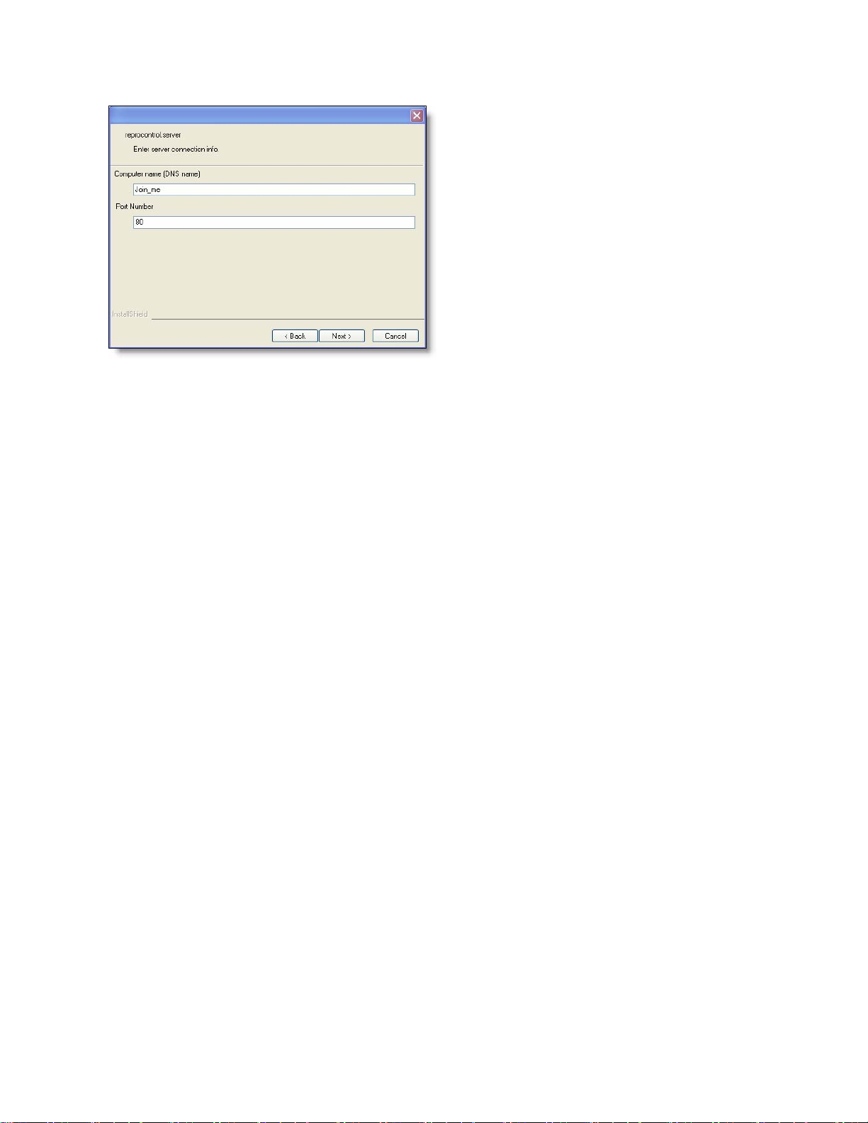
Depending on whether you are NOT going to install the
reprocontrol.server, you have to fill in the correct (DNS-)
name of the computer running reprocontrol.server and
its port. If reprocontrol.server has not changed the
standard port, it ought to be port 80. You may alter the
default port.
If you have to connect with SSL, you have to enter the
correct SSL-number instead. As a default, it ought to be
port 443. Please ask your server/print administration, if
you are not sure what to enter.
Just upon the actual installation of reprocontrol.server
starts, pay attention to a pop up-box that informs you
about the port number that is going to be used by
reprocontrol.server. Usually it should be port 80. If port
80 is already occupied by another application and
service, you have to define another free port.
Equivalently, you will be informed about the SSL-port
number if you have selected SSL previously in the
features selection.
Now the actual installation process begins.
INISH to complete the setup Program after successful installation.
Click F
Now you can start the software from the desktop with the program icon and from the start menu.
Make sure that the Windows user accounts have full access to the parameters folder. To get to this folder,
follow the app_data symbolic link in the installation folder. Usually, SCP parameters folders are set under
“C:\Documents and Settings\All Users\Application Data\SCP”. In Vista the folder is “C:\Program
Data\SCP”. To be granted further rights please ask your system administrator.
11
Page 12
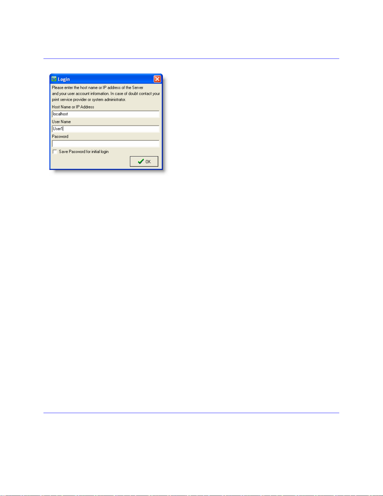
Login
At first start of reprocontrol.client you will be asked for HOST
NAME or IP-ADDRESS of the reprocontrol.server. Put in the
correct name of the hosting computer or its IP-address. Below,
you have to fill in your U
P
ASSWORD into the last line. In case of doubt please contact
your system/print administrator.
If you run a local reprocontrol.server while using
reprocontrol.client on the same system, you should automatically
be connected to the server without entering any further
accounting data except for the first start. A user name containing
your Windows user name will be generated automatically in this
case.
If reprocontrol.client asks for your accounting data under these
conditions, type localhost or the name of your PC as host name.
You may use a password if you like but there is no necessity to
use any due there is only one current user allowed to be logged in the reprocontrol.server.
After the third login failure, the program will be shut down. You can still restart it and try again logging in.
If you want to save the password for future logins, just activate the check box S
LOGIN.
SER NAME. You finally may type in a
AVE PASSWORD FOR INI TIAL
12
Page 13
Keycode Entry
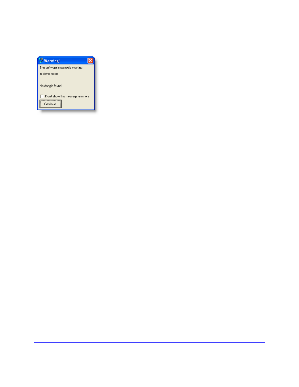
When started for the first time, reprocontrol.client will start up in demo mode.
Features and options are limited in this mode. You will receive a message when
reprocontrol.client starts, indicating the software will start in demo-mode. You may
switch off this message by activating the option D
ANYMORE
under main window’s menu bar option
tab GENERAL.
To disclose the full extent of reprocontrol.client, a keycode is needed which should have been delivered with your
software product. You will also need a licensed dongle. See § INSTALLATION OF THE HARDLOCK to learn more
about licensing.
To enter your Keycode while operating in demo mode proceed as follows:
Go to the menu bar of the reprocontrol.client main window and click on I
Select J
The reprocontrol.monitor appears consequently. Select M
Select the C
The C
Under K
When you are ready, click on OK at the right part of the reprocontrol.monitor window. Reprocontrol.server
will restart. You may have to log in the reprocontrol.client again.
If the key code is valid and correct all features and options are now available.
If the key code is invalid or incorrect, the characters you typed in will become red after clicking on A
The program remains in the demo-mode.
If you plugged in the dongle after software installation, you have to restart the system after entering the
correct keycode in order to unlock the full version of the program.
To learn more about all the different features and functions of the reprocontrol.monitor see §
REPROCONTROL.MONITOR.
OB-MONITOR.
ONFIGURATION option.
ONFIGURATION dialog now opens the monitor-window.
EYCODE you will find a text field where to enter your keycode.
. It is also possible to manage the de-/activation of the demo-message
CONFIGURATION PREFE RENCES
ENU from its menu bar.
ON’T SHOW THIS MESSAGE
NFO.
PPLY.
13
Page 14
Hardware Configuration
To install and configure print/copy devices (printers, queues and clusters) admin-level rights are needed.
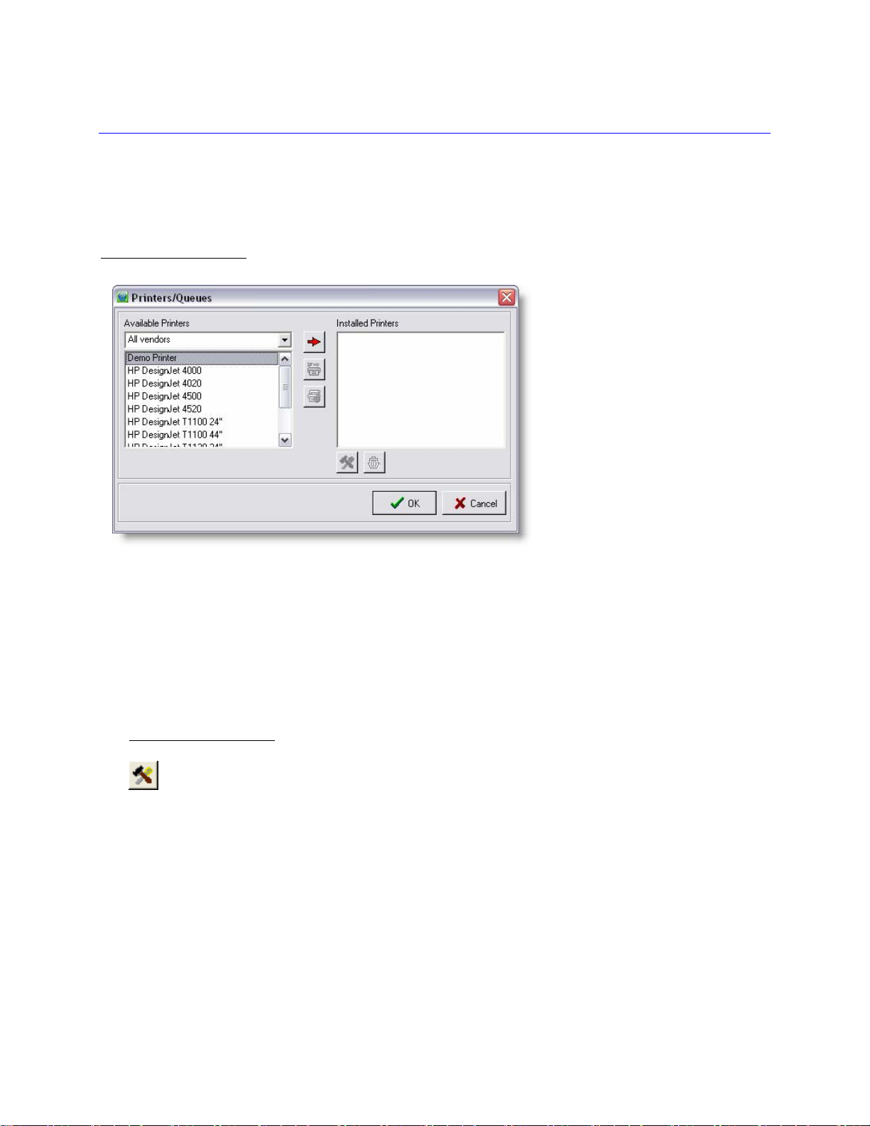
Printers / Queues
The window P
and queue configuration at a later time, go to menu bar C
window (see §
Highlight a printer in the list box AVAILABLE PRINTERS and click on the red arrow button (ADD PRINTER).
Alternatively, you may double-click on the printer.
After selecting a printer, you will automatically be guided to T
RINTERS / QUEUES will appear automatically upon the first start. If you want to access the printer
MENU BAR OPTIONS § CONFIGURATION).
ONFIGURATION PRINTERS/QUEUES to open that
HE CONFIGURATION WIZARD.
Printer Configuration
Clicking on the PRINTER CONFIGURATION button while an installed printer is highlighted opens THE
CONFIGURATION WIZARD. You may also double-click on the printer to do the same.
In case of a highlighted queue the C
cause the same.
For further details about configuring a queue please go to § CREATE QUEUE within this main chapter.
If a Printer Cluster is highlighted, pressing the P
C
ONFIGURE PRINTER CLUSTER.
For further details configuring a Printer Cluster go to §
ONFIGURE QUEUE window will open. You can also use a double-click to
RINTER CONFIGURATION button will take you to the window
CREATE PRINTER CLUSTER.
14
Page 15
Delete Printer
If you want to remove one printer, highlight the printer in question under INSTALLED PRINTERS and
click the D
clicking on an installed printer).
You will unavoidably need the D
If a printer is in use for a queue or cluster, it cannot be deleted: you have to erase the queue and/or cluster first
that is using the printer in question.
ELETE PRINTER button (or click DELETE within the context menu that appears after right-
ELETE button in order to erase installed queues and printer clusters.
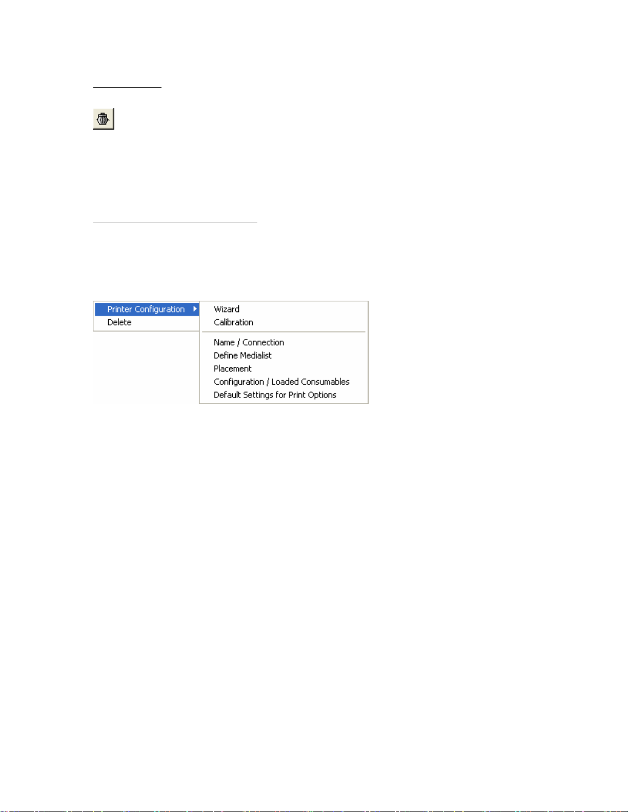
The single Configuration Dialogs
If there are already printers installed and configured for your reprocontrol.server, you can directly open the single
configuration windows, which will be explained in §
Right click on a printer under INSTALLED PRINTERS, highlight PRINTER CONFIGURATION and select the
needed configuration dialog from the context menu:
By using WIZARD you will rerun the configuration wizard for the selected printer.
THE CONFIGURATION WIZARD.
15
Page 16
The Configuration Wizard
The Configuration Wizard guides you through the configuration and calibration of your printers.
The options of the single dialogs are device-dependent.
You get from one dialog into the other via NEXT.
BACK will bring you back to the previous dialog.
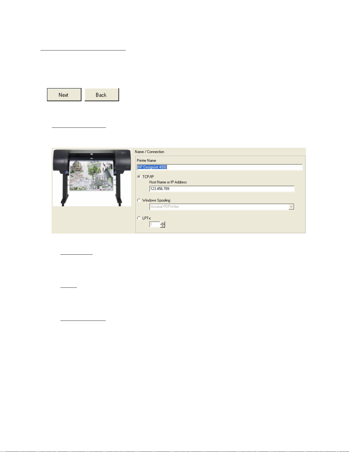
Name / Connection
Enter the type of connection you are going to use.
Printer Name
This text field allows you to change the name of the printer.
TCP/IP
Type in the field the TCP/IP address of your printer.
Windows Spooling
Choose a printer driver for your printer within the drop down list. To avoid editing delays, print jobs are sent to
and stored in a buffer memory until the printer is ready. Windows driver settings are ignored.
When all settings are made, click on N
The software will search for included color/calibration profiles and import them if found. After this the roll
configuration of the printer is checked.
If no profile is found or if you cancel the import, the software will ask if you want to search the ftp-server as an
alternative. If you click on N
LACEMENT. If you decide to search the ftp-server and profiles are available, please select the desired profile
P
created with the appropriate program version. Then click on D
reprocontrol for HP.
EXT.
O or if there are no valid profiles for your printer, you will automatically get to the window
OWNLOAD to import the profile library to your
16
Page 17
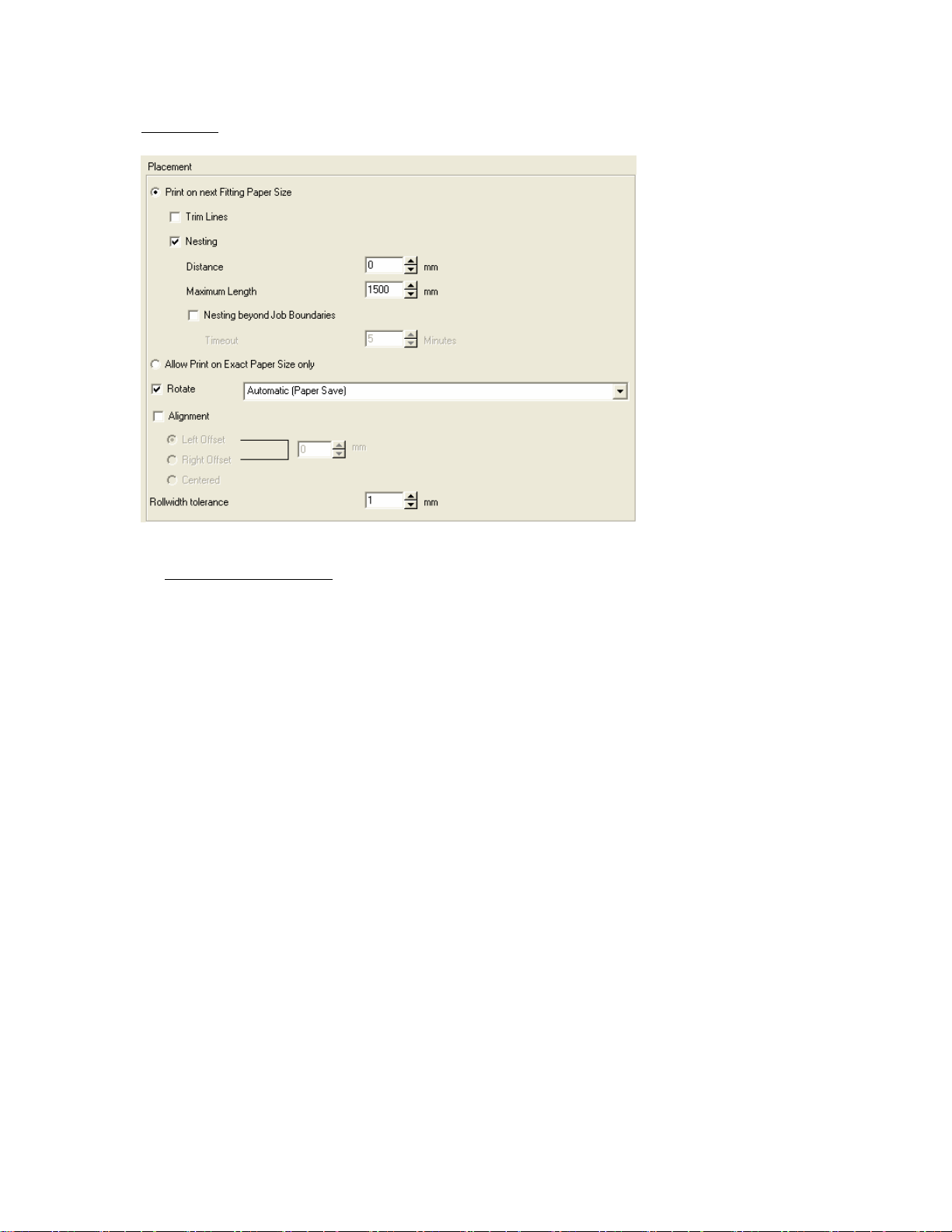
Placement
Define output paper size
First you may choose among two radio buttons whether the printer is A
PAPER SIZE ONLY or the printer is allowed to PRINT ON THE NEXT FITTING PAPER SIZE. If you opt for
the last radio button, further settings become available:
Trim Lines
You may now select TRIM LINES which will appear between each copy of the same paper output. They will
help you to cut these copies manually.
Nesting
you want to print several copies, and at least two copies fit into the print width, enable N
If
COPIES to have the copies automatically printed next to each other.
Distance
You can d
Maximum Length
etermine the size of the area left between copies under D
LLOWed to PRINT ON THE EXACT
EST MULTIPLE
ISTANCE.
Define the maximum length of nested copies.
Nesting beyond job boundaries
Activate this option to allow nesting of two or more print jobs on one paper output.
17
Page 18

Rotate
Without a checkmark at this option pictures are put out with their standard rotation determined by the
document.
If you check this option, you may choose among different rotations-types to be found in the drop down list:
When using AUTOMATIC (PAPER SAVE), the copy will be rotated so that paper can be saved during output.
If you want the output to be rotated without paper-save function, select a rotation degree. They are arranged
clockwise.
Alignment
Select the corresponding radio buttons if you want to have a L
the size of the offset to determine the distance between the paper side’s border and image. Select the
CENTERED-radio button to set the image to the central position instead.
Rollwidth tolerance
If you want to allow print sizes that exceed the print width of your printer, you may define a new tolerated
width. Please bear in mind that this may cause a loss of certain areas of the image (especially at the width
borders).
EFT or RIGHT OFFSET on your print out. Alter
18
Page 19
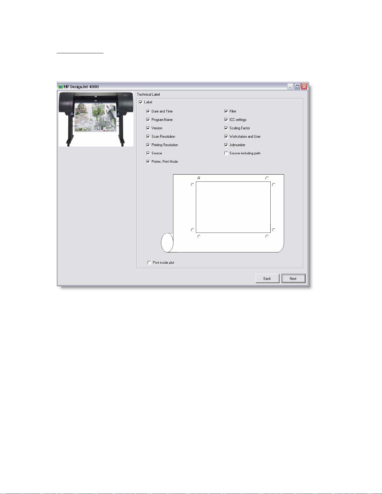
Technical Label
This option will cause an appearance of a LABEL on each copy. Labels are shown close to the copy and inform
about various settings.
You can determine which piece of information the standard label will contain by checking the corresponding
boxes.
Additionally, you may determine where the labels will appear on the print out. Just activate one radio button
which represents the place where the label will appear. If you want the label to be printed inside the image,
activate the P
places where the label will be printed on the picture.
RINT INSIDE PLOT box: the radio buttons will now appear inside the rectangle representing the
19
Page 20
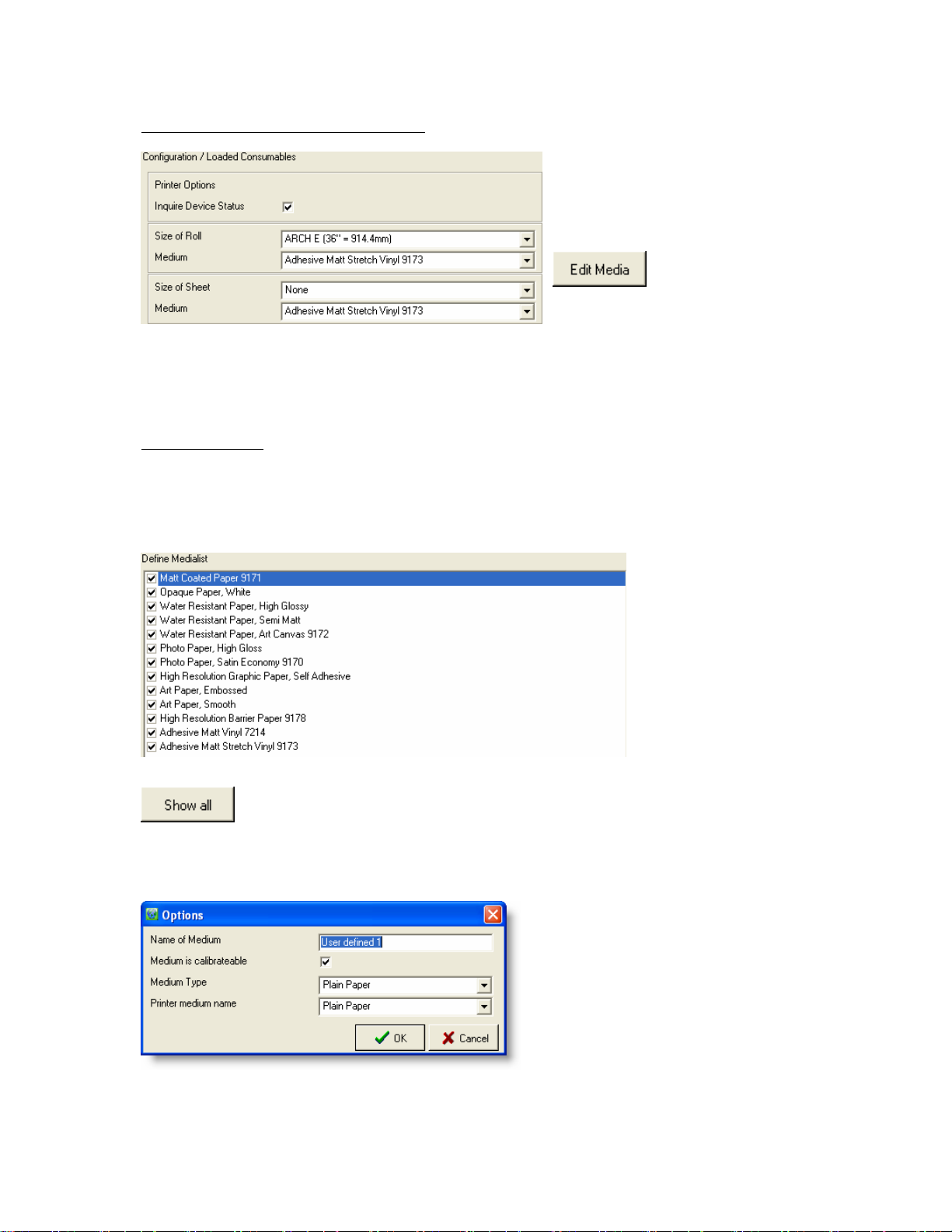
Configuration / Loaded Consumables
The calibration being media-dependent, you
have to select the paper types and ink types
set in the printer.
Printers can be equipped with different
numbers of paper rolls.
If you do not use original media, edit the medium/media you use via E
the preset color profiles are made for original media only.
You get to the dialog
EFINE MEDIA LIST via
D
the button E
DIT MEDIA. This is important as
DIT MEDIA.
Define Medialist
You get to this dialog automatically with the config uration wizard, but also from the PRINTERS/QUEUES window
when you open the right-click context menu of an installed printer and select P
RINTER CONFIGURATION
DEFINE MEDIA LIST, or when you click the button EDIT MEDIA in the configuration dialog CONFIGURATION /
LOADED CONSUMABLES.
To get the list of all medium types and be able to edit user-defined media, click S
HOW ALL.
Select the paper types you want to work with. If you do not use original paper or other original media from the
manufacturer, define your own media: check the box "U
O
PTIONS and define the medium you use.
SER DEFINED 1", open the context menu, highlight
You may need to enter the paper type loaded in
the printer. Enter the paper type according to the
specifications of the media or printer
manufacturer. Wrong printer or software settings
can lead to quality losses!
20
Page 21
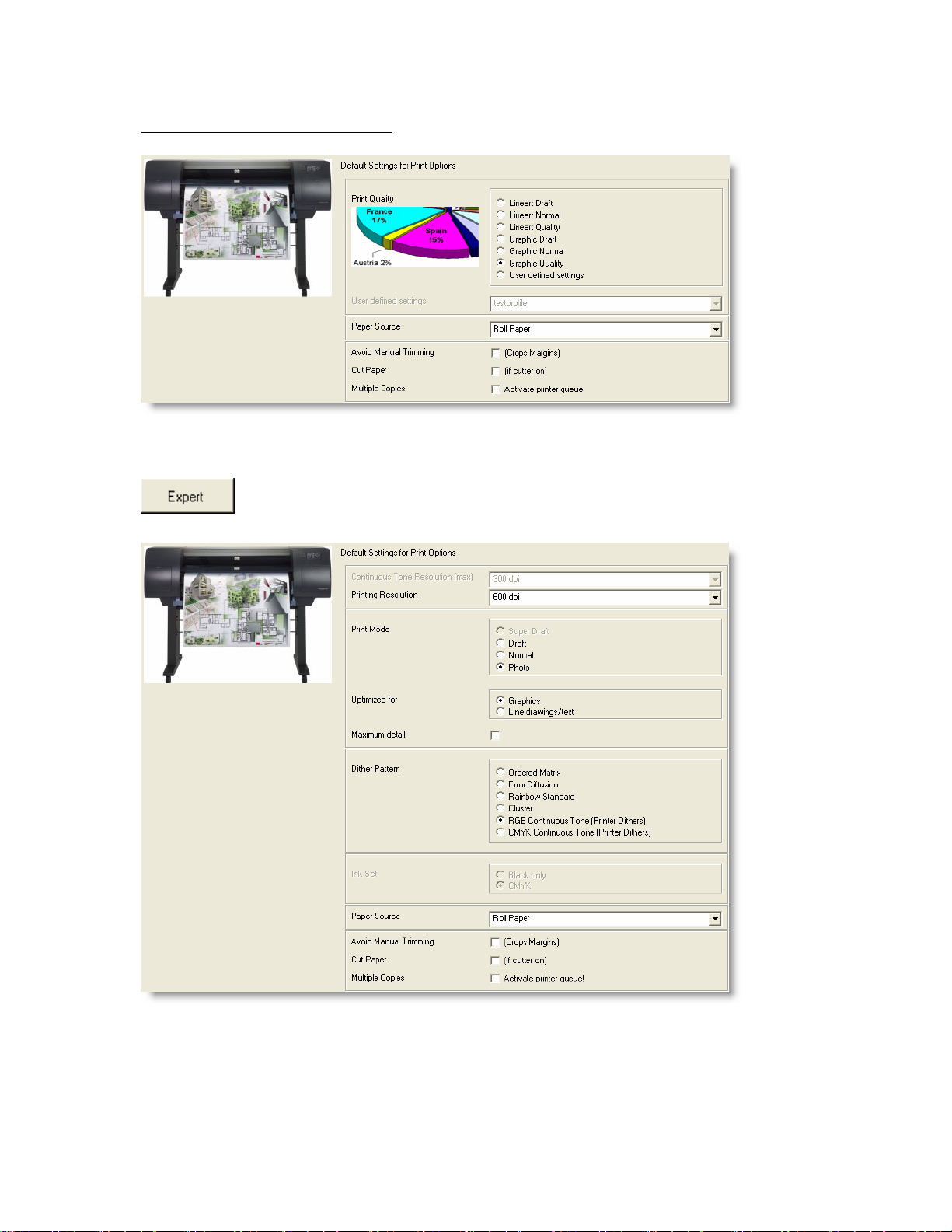
Default Settings for Print Options
Determine the default settings for the connected printer. You can set e.g. the dpi value, as well as trimming and
drying options.
If you need further settings, click the button E
XPERT. The dialog is device-dependent.
21
Page 22
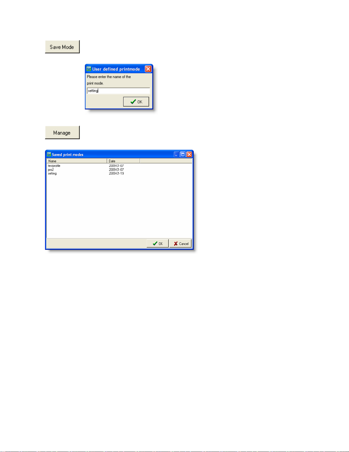
You may save your custom settings for print options by clicking the button SAVE MODE. The
small window U
SER DEFINED PRINTMODE will appear consequently where you have to name
the print options profile.
If you want to activate a settings profile saved earlier, just click the button M
the desired profile from the window S
AVED PRINT MODES by highlighting the profile and clicking
ANAGE. Then select
OK.
When you have run through all steps of configuration/installation, you finally have to click on F
INISH to finish the
process. The device should be installed and operational from now on. Do not forget to click OK within the
RINTERS/QUEUES window in order to save all installations and new/altered configurations.
P
22
Page 23
Calibration
You get to this dialog automatically after the main printer configuration wizard if no color/calibration profile where
found previously. While starting up the dialog, calibrations for your printer are loaded. If you do not want to use
any calibration, please bear in mind that you will not be able to use C
of the print out image may suffer under these circumstances.
To recalibrate printers which have been already fully installed, you can use this dialog, too. To get there, right-
click on an already installed printer in the window P
CONFIGURATION CALIBRATION from the context menu.
Another way to calibrate a printer again, go to the main window’s menu bar section § CONFIGURATION §
CALIBRATION. The calibration dialog is opened for the printer that is selected currently in the drop down list
RINTER within the tab GENERAL.
P
OLOR MANAGEMENT later on. The quality
RINTERS / QUEUES and select PRI NTER
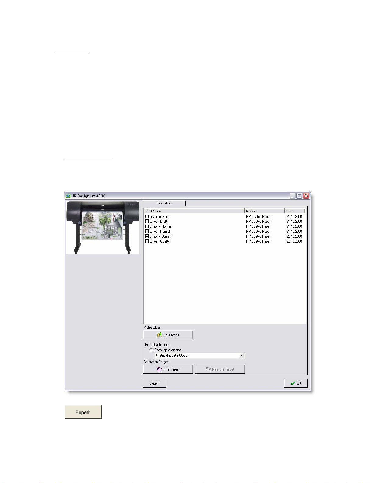
Calibration for RIP
Calibrate the currently selected printer and its media. The medium displayed in the calibration window is that
one you set in the window C
ONFIGURATION / LOADED CONSUMABLES. As a default, the program only
displays recommended print modes.
If you want to calibrate further modes, click the button E
XPERT to get the list of all available
print modes.
When a profile has been successfully applied to the selected copy mode, the date of creation appears behind
the medium name.
23
Page 24
Profile Library
Get Profiles
ith this function you can import calibrations that were made on another system. Open the printer-
W
specific profile library and select the desired filters. If you need libraries, you will be able to
download some from the official web side. Follow the hints online to select and download libraries.
Please consider that the included profile libraries are made for original media from the
printer's manufacturer. If you use different media or feel the quality of the print is not
satisfying, please go to §
Export to Library
ay save all the calibration data by clicking the button Export to Library. You then have to
You m
select a system destination where to save the calibration files.
On-site Calibration
EDIT MEDIA PARAMETERS before proceeding the calibration.
Spectrophotometer
your device for calibration. We recommend calibration with a spectrophotometer for quality
Select
reasons.
Calibration Target
Print Target
Check the boxes of the targets you want to print,
and click on P
printed on the printer you have selected.
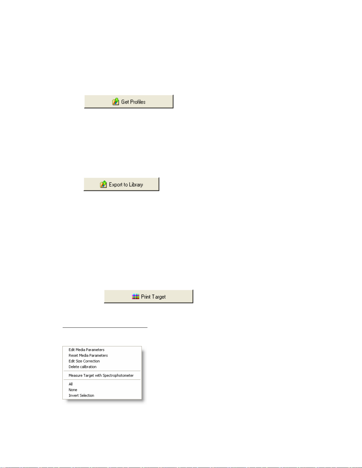
Options in the Calibration Dialog
When right-clicking on the quality settings, the following context menu opens:
RINT TARGET. The targets will be
24
Page 25
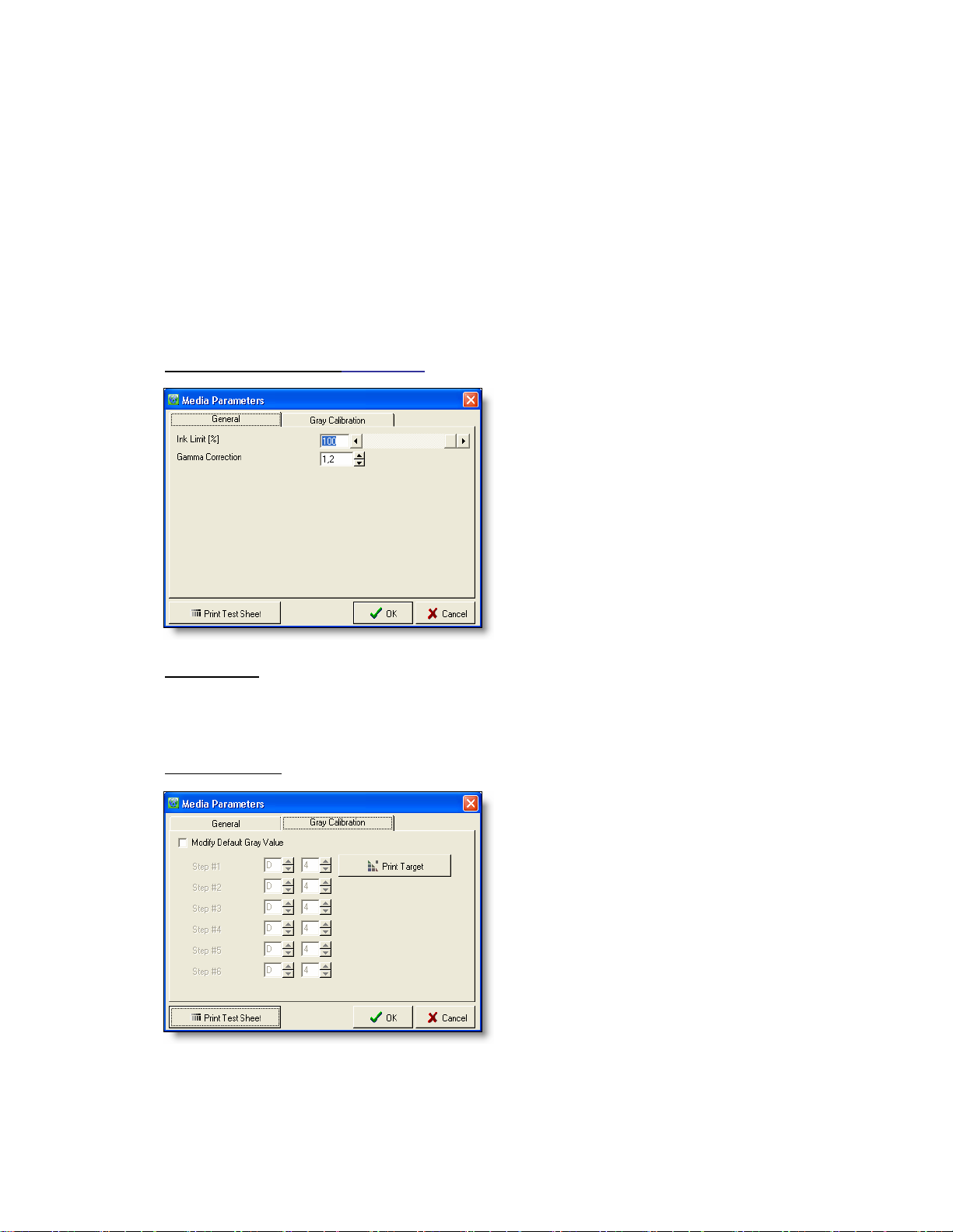
Edit media parameters
Under certain circumstances, for example when you do not use original media, it may be necessary to
change the default media parameters INK-LIMIT OR GAMMA.
These settings may be necessary for each copy mode!
Media parameters should be edited in the order listed below. However, not all steps may be necessary.
1. Define Ink-limit
2. Define Gamma
3. Make greyscale calibration
1. Ink-limit and Gamma (tab GENERAL
)
Print a test page via P
RINT TEST SHEET.
Adjust the ink-limit until all gray areas in the lower
part are clearly visible. The gray areas should not
fade out.
Change the Gamma value until, in the upper part of
the print, the brightness of 50% Gray is exactly in the
middle of the range between 100% White and 100%
Black.
To check the settings, print a scanner-calibrationtarget and look at the colors. If the colors fade out, or
if you can see color droplets, please reduce the ink-
limit value via E
DIT MEDIA PARAMTERS.
Then, print a new target and check the colors.
2. No Black Ink
When available, this option allows you to print without black ink. This option is possible for various printer
types and media (e.g. glossy paper) as some ink types do not dry on certain media.
3. Gray Calibration
A gray calibration may help reduce color shifts in gray
areas.
To make a gray calibration, proceed as follows:
Check the box M
Click P
RINT TARGET to get a calibration target.
ODIFY DEFAULT GRAY VALUE.
Cut out the black & white mask on the left of the
target along the trim lines and take the square out of
the center.
With the mask, find the most neutral gray tone within
each level and enter the corresponding coordinates in
the window.
Check the new settings via P
RINT TEST SHEET.
Reset media parameters
ith this option, the parameters will be reset to the default values.
W
25
Page 26

Edit size correction
During color calibration, correction factors for width and length are
calculated. These factors can be changed manually, for example in
the rare case when the automatic size recognition fails to work.
In this case, proceed as follows:
Set the value for the width and height correction to 100.
Print the file and calculate the difference between the sizes of
original and copy.
Use the rule of three to calculate the correction factor.
Example: the original has a height of 120mm; the copy has a height of 126mm.
The correction factor is calculated as follows: 120 / 1.26 = 95.2381
Values between 90 and 110 are applicable.
Delete Calibration
he saved calibration for the selected print mode will be deleted.
T
Target Selection
With
A
LL, all check boxes will be activated.
ONE, you can deactivate all check boxes with a single click.
With N
With I
NVERT SELECTION, all active check boxes will be deactivated and vice versa.
26
Page 27
Create Queue
For installing a queue push the CREATE QUEUE button within in the PRINTERS/QUEUES window.
Please note that you first need a fully installed and configured printer until you are able to create a queue.
Queues are prearranged printer configurations. Clients may (or even have to) use these fixed settings which e.g.
involve paper and printing size without having to set them up all by themselves. Queues can be arranged for every
installed printer.
Changing prearranged settings of a queue will ask for sufficient rights.
If you had pressed the C
appears: G
ENERAL, OUTPUT OPTIONS, QUEUES and HPGL.
REATE QUEUE button, the CONFIGURE QUEUE window with four tabs consequently
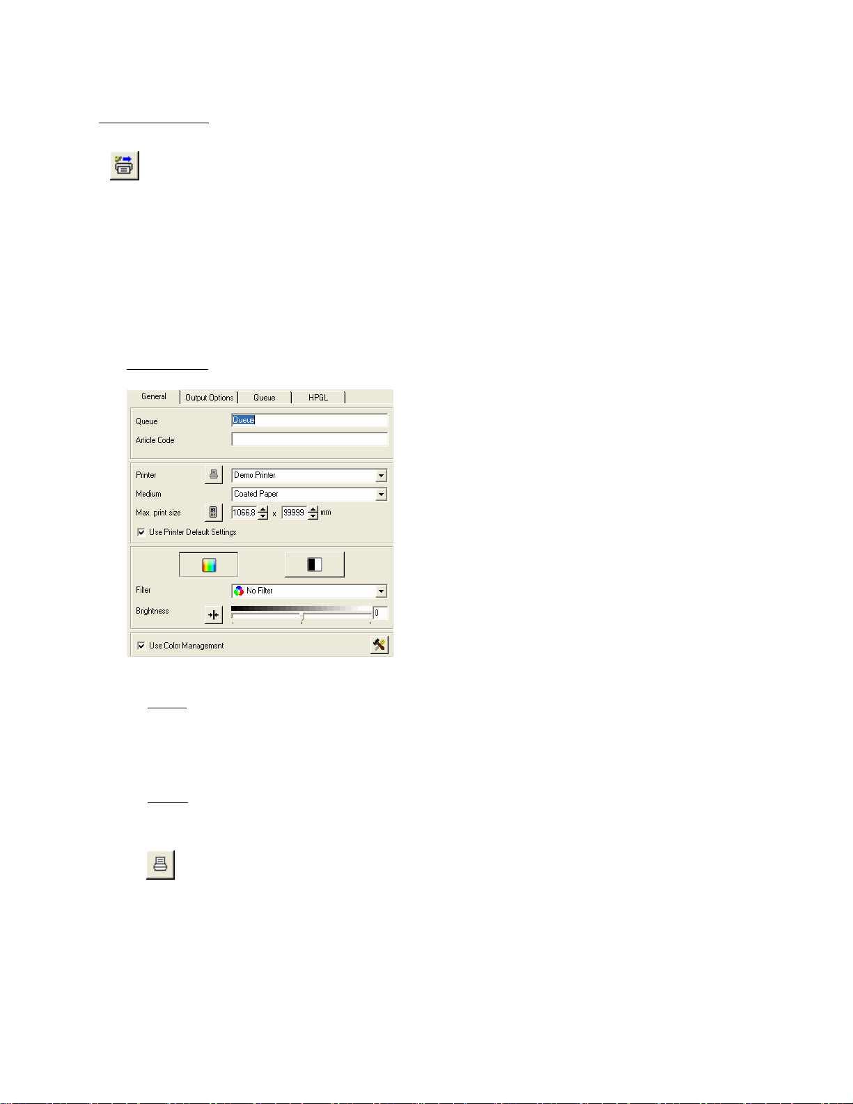
Tab General
Queue
First you may rename the queue under Q
of the printer used for this queue and when to use this queue regarding to reprographic requirements.
UEUE and enter a specific name. The name may include the name
Printer
Now select an installed PRINTER that is going to be used for this queue.
If you want to configure your printer first you have got the opportunity to do so by pressing the
P
RINTER CONFIGURATION button. A dialog with two tabs appears: PLACEMENT and PRINT
OPTIONS. The button PRINTER CONFIGURATION is only accessible if the option USE PRINTER
DEFAULT SETTINGS located below is not activated.
For further details regarding to the options given in this tabs got to §
PLACEMENT / § DEFAULT SETTINGS FOR PRINT OPTIONS.
THE CONFIGURATION WIZARD §
27
Page 28

Medium
You also have to select a M
Set Print Size
Next you can set the MAXIMUM PRINT SIZE. Enter width and length into the two boxes; or simply
leave it to the system detecting the maximum possible print size with the selected printer/medium by
pressing the S
Use Printer Default Settings
You have to activate this option in order to apply all changes of printer configuration settings (e.g. label and
nesting settings) automatically to the associated queue.
Leaving the option inactive, the button P
gain access to the options P
more detailed explained in §
EDIUM used for this queue and its printer. Select one from the drop down list.
ET SIZE button.
RINTER CONFIGURATION becomes available. By pressing it, you
LACEMENT, TECHNICAL LABEL and PRINT OPTIONS. Those options are
THE CONFIGURATION WIZARD.
Picture Edit Settings
Finally you can set the entire color and filter
settings which will take effect on every image sent
to the queue.
Most of the options given in there are identical with
the options given in the tab GENERAL of the main
window. For further details regarding to those
identical functions please go to § EDIT IMAGES AND
OUTPUT
To select and set a customized FILTER within the
queue configuration window, you have to create
one in the FILTER EDITOR first. For further
details, see §
§ TAB GENERAL.
FILTER EDITOR.
28
Page 29

Tab Output Options
In general, this tab offers options to configure the size, number and similar settings of the printed document.
Copies
First enter the desired number of C
Set Output Size
Next you can determine the O
You are able to choose among F
whilst the other parameters are adapted to the altered size automatically.
IT TO SHEET will make the SET SIZE button available. Pressing it you can now choose from
F
different predefined sizes or opt for using the maximum print size that is possible with your
printer/medium and its settings.
OPIES of the same document.
UTPUT SIZE by selecting a scale factor from the SCALE BY drop down menu.
ACTOR, WIDTH and HEIGHT. The chosen parameter becomes alterable
29
Page 30

Tab Queue
Queue description
In this tab you can first enter a personal Q
UEUE DESCRIPTION which will be shown as pop up information in
the main window while pointing at the selected queue.
Priority
You can then set a P
RIORITY for the queue.
N
ORMAL means that the print jobs send to this queue will be processed in normal order.
IGH sets priority to a preferred level, whilst LOW sets a subordinate status. These low priority jobs do not
H
start processing unless higher rated jobs are finished.
De-/Activation of the Queue
Further you can manually activate/deactivate the queue. Simply check the box at A
CTIVE to activate the
queue. As default, it is already active.
Set Time Frame for Queue Activity
You can then define a range of time when the Queue will be active by checking the box at O
FROM
. Now enter the desired time frame.
NLY ACTIVE
30
Page 31

Set User Rights to change Queue
The next options under A
allowed to be overridden by a client with limited rights regardless whether these settings have been
configured by an administrator before. Check each box at those options which you want to unlock for your
clients.
Listen to LPR
If you want to use a LPR connection, activate this option and type the LPR printer name into the text field.
Listen to raw port
If you want to use a TCP/IP port input instead, just type in the correct port number.
LLOW CLIENT TO OVE RRIDE determine which printer settings of this queue are
31
Page 32

Tab HPGL
To determine how to manage HPGL-image files that are sent
to this queue, use this tab.
For a detailed explanation of the functions and options given
in this tab, see
The HPGL-queue configuration only lacks of the option
C
OPIES; all other options are identically.
§ EDIT IMAGES AND OUTPUT TAB HPGL.
When you are done, press OK in order so save and quit the queue configuration. The configured queue is now
available like a printer in the P
Select the queue from the drop down list P
device.
RINTERS / QUEUES window under INSTALLED PRINTERS indicated with a QU.
RINTERS in the main window’s tab GENERAL to use it as your output
32
Page 33

Create Printer Cluster
To install and create a Printer Cluster, click on the CREATE PRIN TER CLUSTER button in the window
RINTERS / QUEUES. At least one printer has to be installed on your reprocontrol.server. To create and
P
alter printer clusters sufficient rights are required.
A printer cluster is a union of multiple printers. Cluster-printers do not have to be of identical type, nor from the
same manufacturer.
Print files that are sent to a Printer Cluster are printed by the next suitable printer of the cluster. The suitable printer
is automatically chosen by the reprocontrol.server depending on the requirements defined by the print files (e.g.
regarding to print/paper size, but even ink level, too).
If more than one printer of the cluster is able to meet the requirements, that device that is not occupied by another
job will print the job; or a multi-file print job is split up and sent to different printers of the cluster.
Typical examples for the use of a printer cluster are:
Load Sharing
A series of inkjets or LED printers, all equipped with the same media and size: Jobs will be distributed to the
printers that are idle in order to increase productivity.
Simulation of a multiroll printer
This is a series of inkjet printers, which are equipped with different media and different sizes. Jobs will be printed
to the correct media and – in order to save paper – to the best fitting roll. In opposite to a multiroll printer all rolls
can be used at the same time.
Cost optimizing
The Printer cluster contains completely different printers like inkjets and LED printer and small format LED
printer. Jobs are distributed to the best fitting printers – e.g. small format to the small format printers, b&w large
format to the LED printers and color large format to the inkjets.
The administrator may select following options when configuring the cluster.
Similar to a queue, a printer cluster can be preset regarding to various print settings.
Preset cluster printouts with these tabs: G
ENERAL, OUTPUT OPTIONS, QUEUE and HPGL.
33
Page 34

Tab General
Cluster
Enter a distinctive name for your cluster. You may e.g. specify when to use this cluster regarding to
reprographic requirements.
Article Code
You may further add a article code for the cluster.
Printer
All installed printers are listed in the field. Activate each corresponding checkbox corresponding to a printer
which you want to be part of your printer cluster.
PRINTER DEFAULT SETTINGS is not activated.
Medium
Select the desired output medium the cluster has to work with from the drop down list. Choose/leave it at
ANY, if there is no necessary special preset for the media.
By using the button P
where you may alter the print quality if necessary. The button is only accessible if the option U
RINTER CONFIGURATION left of it you get to the dialog PRINT OPTIONS,
SE
34
Page 35

Max. Print size
Set the maximum possible print size of your cluster. Click on the S
the maximum print size determined by the printers that are currently selected to form a cluster.
Use Printer Default Settings
Similar to the option named identically in the queue configuration, the check box U
SETTINGS allows setting to apply changes of the printer settings to automatically to the associated queue.
If the option is inactive, you get access to the button PRINTER CONFIGURATION offering the sole dialog
RINT OPTIONS.
P
Picture Edit Settings
See §
CREATE QUEUE § PICTURE EDIT SETTINGS for similar information relating to the options given
ET SIZE button to auto-calculate
SE PRINTER DEFAULT
35
Page 36

Tab Output Options
See § CREATE QUEUE
§ TAB GENERAL to obtain explanations about the same options.
Tab Queue
Go to § TAB QUEUE within § CREATE QUEUE to learn more about the options given in this tab: they are for the most
part identical except of the following ones:
Distribute jobs among similar prin
If this option is enabled, all files of a set are distributed to multiple printers. If you want to keep the jobs of a
set together you should disable this option.
Allow monochrome prints on color printers
This option should be switched on if there are no b&w printers in the cluster. If there are b&w printers, that
option should be checked in order to save time and money.
Wait for best fitting Printer when busy
If this option is selected the job will be postponed until the best fitting printer is idle. If this option is not
checked reprocontrol.server will use the next best fitting printer available.
ters of the cluster
Tab HPGL
Compare § EDIT IMAGES AND OUTPUT
As with HPGL-presetting used for queues, tab HPGL within a printer cluster-configuration lacks of the option
COPIES.
When you are done, press OK in order so save and quit the cluster configuration. The configured cluster is now
available like a printer in the P
Select the cluster as your output device in the drop down list P
§ TAB HPGL to get explanations for the same options.
RINTERS / QUEUES window under INSTALLED PRINTERS indicated with a CL.
RINTERS in the main window’s tab GENERAL.
36
Page 37

Preferences
To get to the window PREFERENCES, click CONFIGURATION in the menu bar, then PREFERENCES.
The PREFEREN CES-dialog offer very important additional hardware- and software settings.
Tab General
Paper Format
You can choose a standard ISO or US format and define your own formats.
ISO – DIN formats are selected as standard formats.
US – US formats are selected as standard.
USER
Create user-defined formats
DEFINED – customized formats will be applied.
1. In the drop down list under P
SIZES.
2. A dialog opens in which you can adjust user-defined formats and select ISO and/or US formats
additionally.
APER FORMAT, select USER DEFINED and click on EDIT PAPER
37
Page 38

Unit
Select MILLIMETER or INCH from the drop down list.
Simple filter editor by Default for RIP
If this check box is checked, the filter editor will be displayed in the simple mode.
Learn more about the filter editor by referring to § FILTER EDITOR.
Use Screen ICC Profile
If you want to use the ICC profile of the operating system for your screen, check the corresponding box. (ICC
profiles are only supported by Windows 98, Windows 2000 and XP)
Show warning for demo version
Check this box to activate the warning message window which shows up every time you start reprocontrol.client
without a licensed dongle and keycode. You also can deactivate this message in the message window itself. Go
to the main chapter § KEYCODE ENTRY for further instructions.
Show warning when configuration changes
By activating this box a warning window will appear after various configuration changes.
Show warning when unsaved changes
By selecting this box, you activate a warning message when changes of configuration are not saved.
will be deleted
Start new job after submit
Activate this option in order to automatically delete the job list after submitting. If you want to be asked first
before deleting, activate the lower A
SK ON JOB SUBMIT.
Job number in printer display
By selecting this option, the job number of the current print job is displayed at the printer’s display if available.
38
Page 39

Use compressed transfer
If you have a slow data connection, the option USE COMPRESSED TRANSFER is worth activating. Please bear
in mind that decompressing data will result in a higher system workload.
39
Page 40

Menu Bar Options
This main chapter contains an overview about all the functions available in the menu bar. By using it, you can
manage all the file based applications except of specific arrangements of the documents.
File
By opening FILE given in the menu bar section you can control which files/jobs to print or close the
reprocontrol.client program.
Files to Print Selection
All options in there that have a sign at the left are also available in the button line below the menu bar symbolized
with the same sign.
You can find a more detailed explanation for those commands at §
Exit
This causes leaving and closing reprocontrol.client completely.
FEATURES OF THE TOOLBAR.
40
Page 41

Configuration
In general, you can select and configure all hardware and accounting settings by using this menu bar section.
Printers/Queues
This option will take you to the window PRINTERS/QUEUES as explained in § HARDWARE CONFIGURATION. New
printers as well as queues and clusters can be added and existing hardware installations can be altered.
Calibration
This is another alternative to reach the calibration dialog which is explained more detailed in § CALIBRATION of the
§
HARDWARE CONFIGURATION § THE CONFIGURATION WIZARD. By using the menu bar calibration command, you
can start calibrating the printer that is currently activated in the main window.
Preferences
Selecting this menu bar option will take you to the PREFERENCES dialog
The options that are available in this dialogs are very important additional settings for your hardware
configuration, so they are explained separately in §
PREFERENCES seen earlier in this manual.
41
Page 42
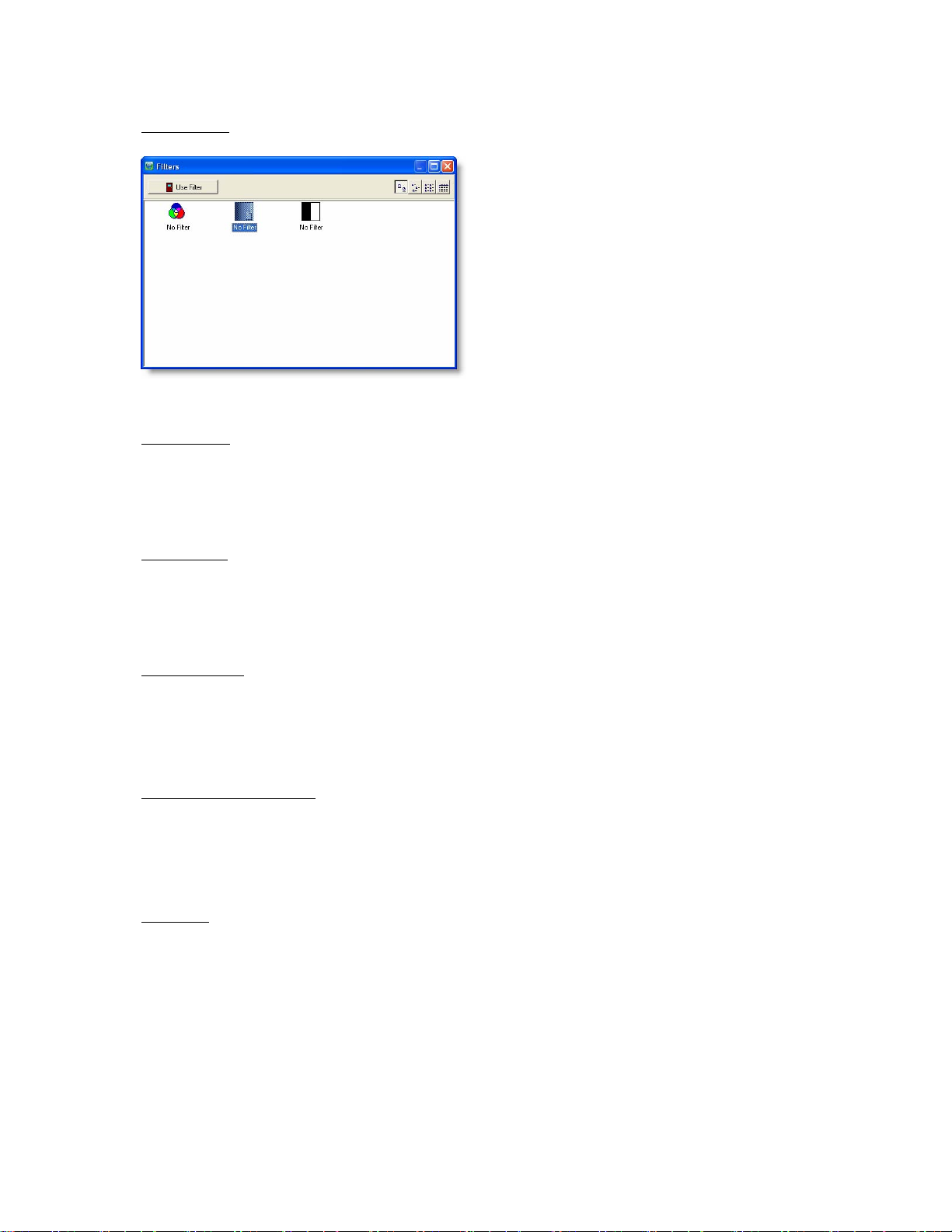
Show filters
If you want to have a look at all the available and
manually created filters, select S
cause the window F
filters you want to use for the current selected image files
by highlighting the filter thumbnail and then pressing the
button U
To learn more about the filter editor, see §
SE FILTER.
ILTERS to appear. You may pick
HOW FILTERS. This will
FILTER EDITOR.
Load preset
This will activate a hardware-profile (consisting of e.g. printer and media that are going to be used for the print
job) that has been saved on your system before. Previous settings are replaced.
Save preset
Choosing this option will save the current hardware-profile that is activated in the main window. You can now
load saved profiles with L
OAD PRESET.
Set as default
The present hardware profile is set as default profile which is loaded every time you start up reprocontrol.client.
Moreover, the standard output device is automatically selected for every recently added file in the job list.
Apply Settings Globally
By using this command, all previously selected files of the job list are retroactively affected by the hardware
profile selected currently.
Log in …
The window LOGIN, which appears after activation, is exactly the same as seen with the first start (see § LOGIN).
42
Page 43

Change password
You may enter a password, but there is no necessity to do so when working
with reprocontrol.client for HP.
43
Page 44

View
Refer to this tab to obtain various display configurations.
Preview
This opens the PREVIEW of the highlighted file. For a detailed explanation of the Preview, go to § PREVIEW.
Show button caption
If deactivated, the toolbar (below the menu bar) is not subtitled. For a description of the tool bar see § FEATURES
OF THE
TOOLBAR.
Show preflight
Check this option to show a little preview image of the highlighted document. It is represented at the bottom of
the main window. It can be both seen in job list screen and in preview screen.
Only one preflight can be represented for the same time.
The arrows at the right of the little preview image allow rotating the image (counter-) clockwise by 90° not
only on screen but on the potential output, too.
Show file path
To display the detailed file path information in the job list column, activate the option SHOW FILE PATH.
44
Page 45

Edit
This menu bar section allows managing selection/position of files in the job list.
All of those options are visible at the left side bar in the main window, too. These commands are also available by
right-clicking on a file in the job list. If you right-click on an empty space in the job list, you will only be able to obtain
commands to control files-selections.
Up
This alters the position of highlighted jobs with the next upper position.
Down
This alters the position of highlighted jobs with the next lower position.
Activate all
Via this command every file in the list becomes checked and can all be submitted to the print server by
using the S
Deactivate all
By using this icon none of the files in the job list gets a checkmark and existing checkmarks are
removed. It is not possible to start printing under these conditions (the S
Switch active
The file selection becomes inverted. When none/all of the boxes were checked, activating inversion is
equal to A
UBMIT button.
UBMIT button turns red).
CTIVATE / DEACTIVATE ALL.
45
Page 46

Preview
See § REPROCONTROL.CLIENT MAIN APPLICATIONS § PREVIEW for detailed explanations.
Actions
Submit
All activated files in the job list are sent to the print server. You may also press the large
UBMIT button in the right corner of the main window.
S
Info
In general this option is everything you need to obtain information about your system, print jobs and reprocontrol for
HP.
About
In this window you can obtain everything necessary about your reprocontrol.client version. You can get to the
developer’s homepage by clicking the http address, too.
Job Monitor
This opens the reprocontrol.monitor. This service is an important helpful tool of repr ocontrol for HP, which makes
it possible to watch and control submitted print jobs.
To learn more about the essential reprocontrol.monitor see §
REPROCONTROL.MONITOR.
Costtracker
Switch to the separate cost tracking program to check and control your print costs.
To learn more about this tool go to §
COSTTRACKER.
46
Page 47

Help
By using this option you can switch to the reprocontrol.client online help. Select the chapter of interest and
double click to open up a main chapter including subchapters. Use the menu bar at the top to activate further
options.
47
Page 48

Reprocontrol.client main applications
Basics
Added files are shown in the job list. To add files see § FEATURES OF THE TOOL BAR.
Files in the job list are categorized with nine different columns: #; N
S
IZE, PRINTER, STATUS and FINISHING.
Furthermore, there is a symbol at the very left of each file indicating whether it is e.g. a color or b&w document.
The position of files in the job list can further be altered by clicking on one of these column categories which causes
a climb down order regarding to the selected category. Clicking again on the same category causes a climb up
order.
Files can also be moved from one position to another within the job list by using drag’n drop.
To manage the addition of files activate the corresponding commands given in the menu bar under F
the toolbar given in the main window.
To modify documents and its output medium, it is necessary that at least one file is highlighted.
Bear in mind that some of the settings for picture quality/color, output media etc. will only be accessible, if no more
than one file is highlighted. An information bubble pops up, if a tool pointed to will not work under multi-file
conditions.
If no file is highlighted, you can only control the JOB COUNT (for editing the
number of printouts of the same job) and the R
both at the lower part of the main window’s tab-area.
Activate P
Learn more about this topic in the following §
If one or multiple files have been selected you may start printing by using the large PRINT button at the bottom’s
right hand side corner.
REVIEW when only one file is highlighted. A Preview will assist you finding the best edit for your pictures.
REPROCONTROL.CLIENT MAIN APPLICATIONS § PREVIEW.
If no file is selected or problems with hardware or media configurations occurred, the button will
appear red. By pointing at the red button with the mouse cursor, a little information bubble will
appear which informs about the cause of the problem. Also pay attention to red entries in the tab
area indicating corrupted or incomplete hardware settings/installations (point at them with the
mouse cursor to learn more about the problem).
When all settings are set in accordance with your system and at least one file is checked, the
SUBMIT button becomes green. You can now start printing.
AME, COPIES, SIZE, DIMENSIONS, PRINT
ILES or under
EVERSE PRINT ORDER-option
48
Page 49

Features of the Toolbar
As explained in § MENU BAR OPTIONS § FILES the following options are both available at the menu bar options
under F
ILES and at horizontal tool bar. With them you can manage which files to add to the job list.
Add File(s)
Selected files will appear in the job list and can now be edited.
With this option you can add new files to the current job list. This is also possible by right-clicking
anywhere on the job list. A context menu will appear. Choose A
Select the files from the appearing window.
Delete
Highlighted files are erased from the list by using this function. Again, it is alternatively possible to
gain this command by choosing the identical command from the context menu which appears after
right-clicking on one or several files.
Load Job
This loads the job list with a selected job that has been saved before. Existing files in the job list are
replaced with the loaded job.
Insert Job
DD FILES from there.
Saved jobs are added to the files of the current job list.
Save Job
Please note that this command only will save a profile which files are used for the job; it does not save the full
original file data itself. Thus, if the source-files are altered in name and position or are erased, the job profile will
not be restored completely after the next load. If source-files are altered while the current job list is still using
them, the altered files will disappear after the next refresh.
The actual job list profile will be saved on your system. You may now use LOAD / INSERT JOB later
on (explained above).
49
Page 50

Start new job
The job list window will be emptied. You may now create a new job list.
Reload Job
To reload an already submitted job-list with all its incorporated files use this button. If a list is already
presented, you will first be asked whether you want to erase the current job-list and replace it with
the reloaded job. Click YES or NO .
You get to the window RELOAD JOB. Select the desired
job which has been submitted before and press the
button at the right corner. The same files as
used with the previously completed job are
loaded as the new current job-list.
Note: the possibilities of selecting submitted jobs are
determined by settings set in the reprocontrol.monitor. To
learn more about this essential tool go to §
REPROCONTROL.MONITOR.
50
Page 51

Preview
The preview window can be gained by clicking on the symbol PREVIEW at the left side of the main
window; by double-clicking on the file in question, or by selecting P
appears after right-clicking on one file.
It is only possible to open up one preview at the same time. For leaving Preview just activate a preview command
again.
REVIEW from the context menu, which
The preview of the highlighted document is shown within the main window instead of the job list.
REVIEW gives you an impression how the picture will look like after the printout. That means you can watch
The P
all the edits taking effects on the document (regarding to color, sharpness, etc.).
Changing the size of the document will have an effect on the line and column left and above the preview image
which let you know the size of the picture. Furthermore, you can find additional figures about the size of the picture
at the bottom line. However, the actual image on screen itself does not change its representation size.
You can select these following options mostly represented by symbols within the Preview window:
51
Page 52

RIP Preview
The preview has to be recalculated as soon as sizes are changed in the tab GENERAL or if you use a
new original.
Select an Area
An arbitrary area can be defined from the preview: this is the “AOI” or area of interest. To set an area of interest,
draw a rectangle around the desired section, keeping the left mouse button pressed. The size of the defined area
is entered as the COPY SIZE in the tab GENERAL.
The AOI can be enlarged or reduced in any direction. To do this, move the mouse pointer to an edge of the
rectangle so that a double-arrow appears. Move then this arrow in the height or width.
To move the AOI to a new position, click into the AOI and move it while keeping the left mouse button pressed.
Edit AOI
Instead of dragging the AOI
manually, you can exactly determine
its width, height and position and
enter a scaling factor.
To open the window E
right-click into the picture or in the
AOI and select E
DIT AOI.
DIT AOI,
Reset AOI Setting
This option cancels the current AOI. The complete image is displayed again and will be printed in full
size.
Apply Filtering
This option shows the effects caused by the current filtering and color management.
Further details according to Filters and Color Management are explained in §
FILTERS and § FILTER EDITOR.
USE COLOR MANAGEMENT, §
52
Page 53

Show Gamut Warning
The visual appearance of a print may differ if you print the image on printer A or on printer B due to color
limitations of the printers. S
by the connected printer due to its gamut. When this option is activated, the image will be displayed in
grayscale and the deviating colors in red.
HOW GAMUT WARNING allows you to see which colors cannot be rendered
Softproof
SOFTPROOF shows you the difference between the actual image and the print out. Be aware that this
will only work correctly if the screen has been calibrated properly in your operating system.
53
Page 54

Edit Images and Output
Tab General
File
In this field the location, name and format of the selected file is displayed. If several files are highlighted at
the same time, M
Use Color Management
ULTIPLE is displayed.
If you want to work with the color management,
check the box U
necessary, you can select in there an ICM
profile by clicking on the speed button in the
same field. The window C
MANAGEMENT OPTIONS will open.
Beside the lists of RGB- and CMYK ICC-
P
ROFILE, this dialog also offers the TruCAD
color management for HPGL files. So you may
select the color space of a printer and emulate it
on another, as far as the technical possibilities
are given.
SE COLOR MANAGEMENT. If
OLOR
54
Page 55

Original Size
The size of the original (width and height) is shown under O
RIGINAL SIZE.
Print Size
The Print Size can be different from the original size.
By default, the original size entered is taken as the output size. The output size can be increased or
reduced by a percentage. You may of course enter the desired copy size directly in millimeter or inch.
The copy width or length always changes proportionally when you alter one of these parameters.
ET SIZE button opens a menu, where you can pick a predefined size or decide to print with
The S
M
AXIMUM PRINT SIZE depending on the size of the medium in use.
Hint: With the key combination Ctrl and Page-up, the maximum print width will be displayed.
Copies
Enter the number of copies required under C
OPIES. If a test copy is supposed to be done first, set the
number of copies to "1".
The option J
OB COUNT defines the number of repetitions of the same job, whilst COPIES sets the number of the
J
selected document. Just pay attention to the information under the N
JOB COUNT or COPIES parameters.
OB COUNT given below the tab area is not to be confused with the number of COPIES, since
O. column in the job list after altering the
Printer
Select the desired output device from the drop down list which contains all installed printers, printer clusters
and queues. You are able to select different output devices within one print job process.
Note that access to some picture- and output arrangement options may depend on the selected queue or
cluster in this list, since an administrator can reduce functions for clients who work with these devices. Go to
§ CREATE QUEUE TAB QUEUE or § CREATE PRINTER CLUSTER TAB QUEUE to learn the details.
If a printer is not working correctly and/or its installation is corrupted, the name of the device will appear with
red letters. A pop up box will inform you about the error when pointing to the printer name.
The button next to the printer list opens the window for the printer/queue configuration. The dialog for
the printer configuration is device-dependent:
In the tab P
RINT OPTIONS you can change the settings of your printer. In the tab PLACEMENT you
set additional arrangements of the picture.
For further details regarding to this subjects, see §
THE CONFIGURATION WIZARD § PLACEMENT and §
DEFAULT SETTINGS OF THE PRINT OPTIONS.
55
Page 56

Medium
A selection of different media is displayed under M
EDIUM. Select the paper type you want to use for your
output.
All calibrated paper types are displayed with black letters, whereas the paper types with red fonts have not
been calibrated yet or are not available for the selected printer. A description of the problem is shown when
pointing to the medium name.
You will only be able to start the output if you have selected a calibrated paper type.
The list of media can individually be set and calibrated for every printer by clicking on the
configuration button left of the media drop down list. It will take you to the CONFIGURATION /
LOADED CONSUMABLES as known from § THE CONFIGURATION WIZARD. There is again the
possibility to E
DIT MEDIA by using the corresponding button which takes you to the DEFINE MEDIA
dialog.
Print Mode
Select the print mode. You may choose color, gray scale or b/w mode.
The availability of selections is file and device dependent.
Filter
You can select a F
image. All filters that were saved in the filter archive are displayed in the drop-down list under F
ILTER from the drop down menu. Filters are procedures to alter the visual shape of an
ILTER and
can be selected from there.
The Filter *N
The filter *C
O FILTER* means no filter is in effect.
URRENT* is a temporary filter with the settings made in the FILTER EDITOR which have not
been saved yet.
You will get to the filter editor with the menu fields C
down list. Using them you will be able to set a personalized F
HANGE and NEW below the drop
ILTER.
You may save a current or new filter on your system, if you hit the
S
AVE AS button. It becomes achievable after any changes in the
ILTER EDITOR. Enter a filter name which will be at your disposal
F
in the F
ILTER drop down list further on.
Further details referring to creating, changing and saving filters are
described in the §
FILTER EDITOR.
Brightness
You may alter the brightness of a copy with the brightness slider. When using normal originals, we
recommend setting the value of the slider to 0. Moving the slider to the left (negative values) will result in a
copy darker than the original, whereas moving the slider to the right (positive values) will make a brighter
copy. Clicking on the button R
ESET will reset the slider to its original position.
56
Page 57

Tab HPGL
Pen Settings
If you are working with HPGL files (vector files),
the tab HPGL will be available in the main
window. With these files, the emulation of some
printers is possible.
HPGL/2 files are able to store certain parameters within the file. The usage of this information can be
switched on and off.
PAPER
determined with the parameters within the file. If you deactivate this option the image dimensions is
calculated by the software. Huge white areas outside of the image will not be printed.
PEN WIDTHS – Deactivate this option in order to set the size of the pens manually.
PEN COLORS - Deactivate this option in order to set the pens colors manually.
MERGECONTROL – Controls the merging of different layers. This command works like the menu on most
HP printer displays.
COPIES – Determines if the value for the number of copies is read from the file. If the option is checked,
you cannot set the number of copies in the main window’s tab GENERAL.
SIZE – If this option is active the image dimension are – regardless of the file content –
57
Page 58

User Pen Settings
Under
USER PEN SETTINGS, you can alter the line
thickness and RGB colors of pens and overwrite the
values determined from the file. If you are working
with a HPGL file (not HPGL/2), you have to
coordinate the pen width and the pen color.
These files can only be edited when the menu fields
SE PEN WIDTHS AS DEFINED IN THE FILE and
U
U
SE PEN COLORS AS DEFINES IN THE FILE are
not activated.
The user-defined pen parameters can be saved and
loaded via the icons in the lower part of the HPGL
window.
Change Pen Color
To change color values, click on the box to the right of the RGB value of the corresponding pen. The window
E
DIT COLORS appears on the screen.
Select one of the 48 basic colors.
Confirm with OK.
The selected color is assigned to the corresponding pen.
Repeat this process for each color.
With the menu field DEFINE CUSTOM COLORS, you can define more color tones and save or assign them
to the corresponding pen as user-defined colors.
Save / Load Pen Parameters
You have the option to save the altered pen parameters of a file for later applications using the
icon SAVE. The parameters are then stored under a filename (e.g. customer, employee or
project) that gets the addition "
at any time.
PEN". Using the icon LOAD, the parameter file can be reloaded
Preview
If you click on the button PREVIEW, you will get to the preview window for HPGL files. The HPGL file will be
displayed with the current settings (line thickness, colors, rotate file etc.).
If you want to check details of the drawing, you have the option to enlarge sections. To do so, draw a rectangle
with the left mouse button and click on the button ZOOM IN . This can be repeated several times.
With the button Z
With the cursor keys to the right of the button ZOOM OUT you can move the enlargement half the size of the
section to the right, left, up or down. With the rhombus, the complete picture (full picture) is recovered.
The status line in the lower part of the window shows the size of the window as well as the size of the drawing.
OOM OUT, the drawing can progressively be reduced again.
58
Page 59

Filter Editor
You will get to the filter editor by clicking the buttons N
window. After having started the filter editor, the name of the loaded filter or “N
EW or CHANGE inside the tab GENERAL of the main
EW” is displayed on the upper
boundary of the window. You will start with the simple version of the filter editor. To open the expert level, just press
the button EXPERT at the bottom part of the filter editor window. If you want to activate the expert mode as your
default filter editor, erase the checkmark at S
T
AB GENERAL.
IMPLE FILTER EDITO R to be found at PREFERENCES (menu bar)
The FILTER EDITOR is an indispensable tool which will help you achieve optimal results even with difficult
originals. The filter editor will give you a preview of the copy on the screen. Each altered setting -e.g. black and
white point correction- is immediately displayed on the screen. That way unnecessary test prints are avoided, since
the optimal parameters can be determined before the output is done.
We recommend you to save the settings made for difficult originals as filters for similar documents.
Functions and Structure of the Filter Editor
Depending on the selected color mode and on the color management you will be able to use different editors:
Filter editor in Color Mode without color management
Filter editor in Color Mode with color management
Filter editor in grayscale mode
Filter editor in black and white mode
You have got always or most of the time these following main button commands below the tab-area:
PREVIEW displays or calculates the preview.
SIMPLE will change the filter editor window to a limited, simpler version. Equivalently, when operating in
simple mode, the button will alter to E
OK closes the filter editor; the created filter is taken into the G
CANCEL
closes the filter editor.
Additionally, the button R
ESET resets all alterations to the last saved configuration.
XPERT in order to switch to expert mode.
ENERAL tab without having been saved.
59
Page 60

Furthermore, FILE located in the menu bar of the filter editor window provides the additional options to save filter
edits (S
AVE AS) and LOAD filter edits.
Preview of the Filter Editor
If you click on the button PREVIEW, the complete original is directly displayed in the
VERVIEW window.
O
Simultaneously a small frame is superimposed in the
VERVIEW window.
O
This frame can be moved with the left mouse button.
The image section included in the small frame is shown
enlarged in the zoom.
The zoom window shows the original on the left, the
effect of the filter on the right in a split screen. The
overview and the zoom windows can arbitrarily be
enlarged or reduced and placed anywhere on the
screen.
Right-click within the zoom window to rescale the zoom
factor.
The results of your settings are immediately shown in
the preview. This way, it becomes easier to find optimal
settings without test prints.
60
Page 61

Histogram
The histogram is shown once you have clicked on the button PREVIEW.
The x-axis represents the spread of each color, or its respective brightness values, while the y-axis displays the
frequency of occurrence of each RGB-value. So the x-axis goes from black to white, with values of low intensity
on the left, and values of higher intensity on the right.
The arrow keys allow you to rescale the histogram.
The check boxes on the left side of the histogram allow you to activate or deactivate the single color bars.
Histogramm without color management
Histogramm with color management
61
Page 62

Tab Black and White Point (Color Mode without Color Management)
You can adjust the black and white points to ensure
colors will be rendered with fidelity. The black and
white points can be set with the static or
dynamic/adaptive method.
Setting the Black and White Points with the Pickers
Pickers are only available, if S
TATIC is activated. Click at PREVIEW on the icon of the black or white
picker. Draw a box around the black or white area of the image that is to serve as a reference. The
average color value of the selected area will be assigned to the black or white point and automatically
corrected.
Black Point
Adaptive
he adaptive values cannot be edited; they are calculated for every file.
T
If the black values contain colors, please check the box C
ONSIDER CHROMA to remove them.
Example: you have scanned a newspaper page. The scanner read the black of the letters as dark gray with
red tones. If a filter is calculated for this document without C
black with red tones, whereas the option C
ONSIDER CHROMA will ensure the printing of the letters in black.
ONSIDER CHROMA, the letters will be printed in
You can see the result in the preview.
If you want to edit the values of the adaptive filter, please click on the button M
AKE STATIC.
62
Page 63

Static
You can directly change the values.
Click at the black picker and draw a box around the black area of the image that is to serve as a reference.
The average color value of the selected area will be assigned to the black point and automatically corrected.
If you left-click in the histogram, all colors bars will be set at a given value. If you left-click on the single color
bars, you can set the values individually.
White Point
Adaptive
T
he adaptive values cannot be edited and are calculated for every file.
If the white values contain colors, please check the box CONSIDER CHROMA to remove the colors.
Example: you have scanned a newspaper page. The scanner read white as yellowish. If a filter is calculated
for this document without C
whereas the option C
ONSIDER CHROMA ensures the output will be white.
ONSIDER CHROMA, the white of the newspaper will be printed in yellow,
You can see the result in the preview.
If you want to edit the values of the adaptive filter, please click on the button M
AKE STATIC.
Static
You can d
irectly change the values.
Click at the white picker and draw a box around the white area of the image that is to serve as a reference.
The average color value of the selected area will be assigned to the white point and automatically corrected.
If you right-click in the histogram, all colors bars will be set at a given value. If you right-click on the single
color bars, you can set the values individually.
Contrast
Once you have set the black and white points, you can further edit these values by altering the C
ONTRAST.
The value in the left entry field affects the black point by enhancing it, while the right entry field is intended to
decrease the value of the white point. The picture contrast will be enhanced as a whole.
Example: the following values are set in the entry fields under the histogram:
Black (left) 30, 30, 30 White (right): 230, 230, 230
If you change the contrast values, the aforementioned values will be modified as follows:
Left 0, right 100 Black: 30, 30, 30, White: 230, 230, 230
Left 10, right 100 Black: 50, 50, 50, White: 230, 230, 230
Left 0, right 90 Black: 30, 30, 30, White: 210, 210, 210
Text/Background
With the option T
EXT/BACKGROUND, you can edit a black or white point that was set by the program. For
example, you can create a filter for the background on the basis of an automatic filter with an edited, more
aggressive white point.
This option does not alter the picture contrast but adjusts the black and white point.
63
Page 64

Example: the following values are set in the entry fields under the histogram:
Black (left) 30, 30, 30 White (right): 230, 230, 230
If you enter the following values under TEXT/BACKGROUND, the aforementioned values will be modified as
follows:
Left 0, right 100 Black: 30, 30, 30, White: 230, 230, 230
Left 10, right 100 Black: 50, 50, 50, White: 230, 230, 230
(values under 50 become black)
Left 0, right 90 Black: 30, 30, 30, White: 210, 210, 210
(values over 210 become white)
Tab Postprocessing (Black & White Mode)
Despeckling
This option removes black pixels in black & white mode, for example from scans of murky originals. The filter
searches for groups of black pixels and converts them into white. Small-sized pixel groups, such as those
forming punctuation dots, are kept.
ALL
FILTER
REL.
PIXEL NEIGHBORS - Pixels are connected neighbors when there is a series of 8 (instead
of 4) adjacent pixels, i.e. additionally to pixels of the same row or column, the diagonally-adjacent
pixels are considered to be connected.
SIZE – It corresponds to the maximum "diameter" of the pixel area which is to be
removed.
AREA SIZE – This limits the proportion of the actual maximum number of pixels to the filter
size. 0 represents the smallest possible surface relatively to the selected filter size.
To use this filter:
Select an ar
In the zoom window, open the context menu and select the view 2:1 or 4:1.
In this view, the removed pixels will appear in light gray.
When you make settings with the despeckling filter, be sure not to remove small elements.
If the unwanted pixels form a round area, set the filter size between 70%-100%. If the pixels stretch on a line,
the filter size should lie under 70%.
ea with black pixels in the preview.
64
Page 65

Hole Filling
This function makes it possible to remove single pixel-sized white holes from black areas in b&w mode.
HOLE FILLING works like DESPECKLING except of not removing black pixels but white.
Inverted
This function shows a negative version of the picture.
65
Page 66

Tab Gamma Correction (Color Mode without Color Management)
A gamma correction allows the adjustment of color shifts in
the middle tone range.
Gamma (Gamma sliders)
You can select between the color spaces RGB (Red, Green, Blue) and CMY (Cyan, Magenta, Yellow). If
you move all sliders at once, you will change the brightness of the image as a whole.
If you choose RGB, you will be able to alter the red, green and blue shifts. If your picture has, say, red shifts,
you will neutralize this effect by reducing the gamma value of the red color bar.
If you choose CMY, you will be able to alter the cyan, magenta and yellow values. If your picture has, say,
cyan shifts, you will neutralize this effect by reducing the gamma value of the cyan color bar.
Value range: 0.433 to 3.185
Default value: 1.0
Gray Balance
this option when your devices have failed to recognize colors. Do not U
Select
with this option.
Click the color picker and select a homogenous zone in the image that should represent the average of the
grey tones. As an alternative, enter the values for the scanner colors in the entry fields.
SE COLOR MANAGEMENT
66
Page 67

Tab Enhancement (Color Mode with Color Management)
For an optimal luminance adjustment the black and
white points can be set. The contrast filters
determine two points for each color channel (red,
green, and blue). Each color value below the first
point will be interpreted as black; similarly, each
color value above the second point is seen as white
to ensure that the scanned original will contain a
"pure" white without a gray haze and a "pure" black
with full saturation.
The values ranging between the two points will be
transformed to the full contrast range of 0% to 100
% to guarantee an optimal color reproduction.
You can set the black point on the left side of the
slider with the left mouse button and the white point
on the right side with the right mouse button. You
can also directly enter values in the entry fields.
Setting the Black and White Points with the Pickers
The histogram is flanked with color pickers: the one on the left is for the black point, while the
color picker on the right is for the white point.
To define a reference area as the black point, click on the black color picker and select a dark area in the
image by drawing a box around it, keeping the mouse button pressed.
The averaged color value of the selected area will be assigned to the black point, and automatically
corrected.
Proceed likewise for the white point choosing a white area in the image.
Sliders for the White Point
With the two sliders below the histogram, you can simply filter out a color drift or tune the colors.
Both sliders set the white point. Move them to the left or to the right to reach the best result. The upper slider
controls green and red; the lower is for blue and yellow.
67
Page 68

Tab Special Filter (All Modes
This tab offers several methods to change the extent of sharpness of the whole image or of specific elements of
it.
except of
Black & White Mode)
None
If N
ONE is selected, no special filter is in use. All options are not accessible under these circumstances.
Adaptive Sharpness
This option reduces print raster.
By combining the smoothening and sharpening filters, ADAPTIVE SHARPNESS softens the image sections
with constant colors in order to make raster virtually invisible.
Object edges and text remain sharp and can even be sharpened.
You can enter values for the L
corresponding to the “coordinates” of the filters in the diagram.
Level
You can s
poor contrast or image backgrounds are edited with the lower entry field, whereas the highly contrasted
sections, such as text and edges, are edited with the upper field.
0: max. smoothing
100: max. sharpening
Default value: 0 - 100
et the level, or intensity, of the sharpening and softening filters individually. Picture sections with
EVEL and LIMIT directly in the entry fields or move the white squares
68
Page 69

Limit
You can determine for each filter up to which or from which value they will work. The left entry field works in
combination with the smoothing filter (lower field under LEVEL); the right one with the sharpening filter.
Picture sections whose contrast is under the value set in the left field will be smoothened; sections with
contrast values greater than the figure entered in the left field will be sharpened. Pictures sections with
contrast values between those of the left and right fields will be sharpened or softened according to their
contrast.
100: max. contrast
Default value: 30 – 50
Display Transfer Function
Activate this check box to check the effects of sharpness and smoothing filters. Areas that have been
sharpened are displayed black; areas appearing white have been smoothed. By using the D
ISPLAY
TRANSFER FUNCTION option it is easier to find a clear edit.
Hint: Using the adaptive sharpness filter
HARP and SMOOTH are combined in ADAPTIVE SHARPNESS to allow you to reduce apparent raster
S
pattern without undesirable side-effect: text and edges remain sharp and can even be sharpened.
A
DAPTIVE SHARPNESS is made of two unique filters, both possessing the features of SHARP and
MOOTH, whose intensity can be adjusted in the entry fields under LEVEL. The upper entry field controls
S
foreground objects that should be enhanced, such as text, whereas the lower field is for image backgrounds
needing smoothing. With both filters, you will reach a maximum smoothing effect at 0 and a maximum
sharpening effect at 100.
L
IMIT works as a threshold. The figures entered on the abscissa are contrast values. 0 stands for minimum
contrast, 100 for maximum contrast.
The left entry field is dedicated to the background and affects the smoothing filter, which will be applied up to
the value entered. In the right entry field, corresponding to foreground objects and the sharpening filter, enter
a value from which the sharpening filter will be applied.
Both smoothing and sharpening filters will be applied to values between the two ones entered as L
IMIT.
If you want to be supported by finding an adaptive sharpness, click the button C
ALCULATE
ADAPTIVE SHARPNESS VALUE. Now you are enabled to draw a rectangle area in the little
REVIEW or ZOOM window. Note that the area should not be too small and the area is
P
homogeneously filled with raster. After successfully selecting an area, the values of LEVEL, LIMIT and
FILTER RADIUS (explained above) are automatically adapted.
To use this filter:
Open the filter editor and select the tab SPECIAL FILTER.
Make a P
Select A
REVIEW.
DAPTIVE SHARPNESS.
Now look in our before/after illustrations at the effects reached by the adaptive-sharpness filter:
Step 1: Setting the level of the smoothening filter
Move the boxes to the extreme right in the histogram, at about the middle in the height.
You will see raster pattern in the zoom window. Move the left or lower box towards the bottom of the
histogram until the raster pattern disappears. Usually, the box must be moved almost to the base of the
histogram.
69
Page 70

Step 2: Setting the level of the sharpening filter:
Move both boxes to the extreme left, but leave their position in the height unchanged.
In the zoom window, look at text sharpness. Move the upper box upwards until text is sharp enough.
Step 3: Setting the limit:
Move first the upper box, then the lower box to the left without changing their position in the height, until
raster pattern disappears and text is sharpened.
To see the effect of the filter A
DAPTIVE SHARPNESS, activate the radio button NONE and compare the
results you had achieved with the original image.
To edit a filter already existing, open the filter editor via the button C
HANGE, and click on the tab SPECIAL
FILTER.
Display a preview.
Activate the radio button ADAPTIVE SHARPNESS.
To reduce raster pattern in single-color area, enter a lower value in the bottom field under LEVEL in order to
get a greater smoothing effect.
Enter a larger value in the left L
IMIT field to apply the smoothing filter to areas with higher contrast.
To enhance edge sharpness, enter a bigger value in the upper field under LEVEL in order to get a greater
sharpening effect.
Enter a smaller value in the right L
IMIT field to lower the threshold from which the sharpening filter is active.
Smooth
This filter is intended to reduce image noise and distortions, and affects the whole picture contrast.
Edit the picture with the slider.
0: no smoothing
100: max. smoothing
Default value: 50
Sharp
With S
HARP, you will be able to make fuzzy pictures clear. As outlines are enhanced, pictures become
clearer. This filter increases the contrast between light and dark pixels and enhances the edge sharpness of
text and lines drastically.
0: no sharpening
100: max. sharpening
Default value: 50
Filter Radius [µm]
You may additionally fine-tune the effects of the current selected special filter (including A
HARPNESS, SMOOTH and SHARP), by altering the filter radius. The FILTER RADIUS slide bar will change
S
DAPTIVE
the number of pixels that are affected by the current filter.
70
Page 71

Tab Color Adjust (Color Mode with Color Management)
The tab COLOR ADJUS T allows a fine tuning of the
colors in the L
You can set contrast and brightness in a range from -60 to
+60.
The saturation channels are two half axes of the a- and bchannels. They can me modified either separately or all at
once.
If you want to change them simultaneously, please
activate the checkbox right of the controls.
AB color space.
71
Page 72

Tab Color Exchange (Color Mode with Color Management)
In this tab, you will be able to select a color or a color
range and substitute it by another color or color range
with a color-exchange filter. For each manual filter you
can define an unlimited number of color exchange filters.
Using the icon A
a color exchange filter.
Delete unwanted filters with the bin.
The arrow keys change the order of filters.
To exchange one color or color range:
Click the icon A
Draw a frame in the preview or zoom window around an
area containing the color(s) you want to replace.
The C
OLOR EXCHANGE window will appear.
The values in the input box under S
OURCE COLOR are determined by the color(s) contained in the frame you
draw.
ADIUS value determines how many colors are to be replaced (one color: Radius=0). This, however, only
The R
makes sense if the frame you drew contains only pixels of the same color or if you want to change a range of
colors (Radius>0).
In the lower part of the window you can define the target color. Depending on which color space you decide to
work in, please choose one of the tabs LAB, RGB, CMYK or HKS.
If you choose the LAB color space, set the target color by changing the values for the L-, a- and b-channels.
In the RGB color space please set the target color by changing the R-, G- and B-channels:
In the CMYK color space, please set the target color by changing the C-, M- , Y- and K-channels:
In the HKS color space, please set the target color by selecting the HKS number. A color sample behind the
number will indicate the color:
DD COLOR REPLACEMENT, you create
DD COLOR REPLACEMENT.
72
Page 73

Lab Color Space
The LAB color space displays the colors in a sphere with three axes:
the L-axis
the a-axis
the b-axis
The L-axis ranges from 0 to 100 and controls the luminance.
A and b-axes determine the color. They range from -127 to 127.
The following diagram shows how the axes are positioned.
The LAB model is built on the insight that the human eye can see some colors distinctly, while it can perceive
others only vaguely.
73
Page 74

Reprocontrol.WinDriver
If you want to use the print capacity of the reprocontrol.server without using a reprocontrol.client and instead want to
use another image application in order to edit, set and configure pictures and print outs, you may install and use the
reprocontrol.WinDriver to send print jobs to the reprocontrol.server.
You have to install the WinDriver separately aside from the main programs. The installation files are located in the
RCWINDRIVER.
folder
The reprocontrol.WinDriver is as a standard windows driver and can therefore be configured like any other standard
print driver by opening the control panel of your Windows system. Print jobs sent by a reprocontrol.WinDriver will be
accepted as a client-application by the reprocontrol.server, if they log in successfully.
After installing the driver, the system tray icon P
A
UTOSTART folder of your system.
Before you are able to start the WinDriver installation you may enter the correct server-name and the correct port-
number in order to log in reprocontrol.server. Click the system tray icon with the right mouse button to open the
context menu where you should select LOGIN in order to log in the reprocontrol.server.
Please bear in mind that you need at least one queue or printer cluster to make full use of the
reprocontrol.WinDriver. To learn how to install a queue/printer, see §
/ §
CREATE PRINTER CLUSTER.
RINTER CONNECTION will appear. It is also located in the
HARDWARE CONFIGURATION § CREATE QUEUE
74
Page 75

WinDriver Settings
After activating the PRINTER CONNECTION (e.g. by using the system tray icon), the window SCP
REPROCONTROL FOR H.PRINTER CONNECTION will appear.
All settings are saved with the button OK. All settings are cancelled by clicking CANCEL.
Tab Settings
Use last settings
If you want to save all settings (including the selected print device and print mode later on), put a checkmark
into this box.
Show finish message
After printing with the WinDriver you may allow a message indicating the job finished being printed.
Tab Log
Activate ENABLE TRACES to enable a full history.
Check the history of previous WinDriver activities by displaying the tab LOG. Save the logbook
by pressing the button S
AVE LOG…
75
Page 76

Using the WinDriver
To use the WinDriver while working with an image configuration application that is not a reprocontrol for HP
application, proceed as explained below:
Open the print file with the application of your choice (this may be just a standard application provided by
your operating system).
Select the print option of the application.
If it is not already activated: select the driver R
Confirm the print command.
A little window named P
MODE you want to use for the print job. If you have selected USE LAST SETTINGS within the tab
ETTINGS of the SCP REPROCONTROL FOR HP.PRI NTER CONNECTION window explained above,
S
you will not need to select a queue/print mode again after the first confirmation of a queue/cluster and print
mode selection. Deactivate the USE LAST SETTING option to change targets and print modes.
EPROCONTROL.WINDRIVER.
RINTER will appear. You will be asked which TARGET (queue/cluster) and PRINT
Confirm the target and print mode by clicking OK: the actual printing will now start.
If the image has been submitted successfully to the printer, you will receive a notification located at the
system tray icon.
76
Page 77

Reprocontrol.monitor
You can get to reprocontrol.monitor by simply activate the desktop shortcut which is generated with the installation
of the program or use I
Reprocontrol.monitor is a post-management service for all submitted print jobs. You may monitor and control (stop,
delete, etc.) submitted jobs by using its specific features.
The reprocontrol.monitor window with three tabs and additional M
Tab Jobs
NFO JOB MONITOR in the menu bar of the reprocontrol.client’s main window.
ENU at the menu bar will open up.
Submitted jobs are listed. They are categorized via different columns:
O. (number of sequence of received jobs), RECEIPT (date and time), USER NAME (user, who submitted the job),
N
TATUS (number of files done by now compared to files waiting for processing) and finally PRIORITY.
S
Within the column F
name of the file is displayed if you use the + at the left hand side of the job number to open a more detailed
description of the job. If the more detailed display level is put on view, you can also check which printer/print device
will process the job. This information is displayed within the P
to the normal job level, you will only see a printer/queue/cluster-name within the P
the whole job and all its files included use the same print device.
You get more detailed information about the printing status by paying attention to the reference displayed within the
TATUS bar. There are various possible main notifications.
S
Alter the arrangement of jobs and files by selecting the title of each column.
You can also right-click anywhere on the job list to open a context menu, which offers several options to control a
global file selection and to open or close
ILE the number of print documents included to the job is shown - respectively the individual
RINTER/QUEUE column. If you leave the display level
RINTER/QUEUE-column in cases
77
Page 78

Button commands
If one or more job registration is highlighted, they can be controlled with six different commands represented as
buttons at the bottom of the window.
Start
This command is only available if used with jobs that have not yet finished (e.g. if an error occurred or the job
is just in waiting status). Highlighted jobs are released for printing at once or at the next possible step
depending on their priority after activating the S
Pause
This button command holds or cancels every selected jobs and/or their files.
Express
The selected job/single file gets the highest priority. An express job is always printed first regardless of its
sequence position and other defined priorities. Express files and jobs are indicated with an E
the column P
There can only be one express job/file in the list at the same time. If a preferred job/file is done, you may
choose another express job/file or just let the rest of the jobs and its files proceed in regular/predefined order.
Details
First highlight the job in question, then click at the D
As consequence, a window is opened which informs you about the job data and its files. Particularly, pay
attention to error messages in cases of print failures.
RIORITY.
TART command.
ETAILS-button.
XPRESS within
Delete
Selected jobs are removed from the list.
78
Page 79

Tab Printers/Queues
Within this tab you have got the possibility to check the print devices (printers, queues and clusters) in use and its
current activity. You can switch to a more detailed view if you use the + symbol at the left hand side of each device.
If you activate this more detailed level, all print files associated with the print device are listed. A figure next to the
print device’s name indicates the number of print files that are associated with this print device.
Stopped and waiting files can be started if you click the P
RINT NOW icon while the file of interest is highlighted.
Tab Connection
This tab monitors all connections to the reprocontrol.server, including reprocontrol.clients, reprocontrol.prints, and
reprocontrol.monitors.
The connections are described with four different categories: USER NAME (user, who runs the program/service),
IP-A
DDRESS (of the user), MACHINE (name of the computer that runs the program/service) and finally CLIENT-
YPE.
T
79
Page 80

You may control the sessions by using the two red buttons at the bottom of the tab:
ERMINATE SE SSION will close the selected application. TERMINATE ALL USER’S SESSIONS closes every
T
application which shares the same user with the selected session.
Menu Options
By opening MENU in the menu bar of the reprocontrol.monitor window, you get access to the options LOG IN…,
ONFIGURATION and EXIT.
C
Use LOG IN… to log in the reprocontrol.server. T learn more about logging in, see § LOGIN.
Use EXIT to close and leave reprocontrol.monitor.
If you choose CONFIGURATION you will open a new window.
The C
ONFIGURATION options are explained in detail below:
80
Page 81

Tab Configuration
Keycode
You have to enter the correct keycode to unlock the full extent of all the reprocontrol.client features. Otherwise,
only the limited demo mode is available. The code will be kept here to take a look at it later on.
Go back to §
Below the keycode entry, you will see text notifications about the dongle status and number.
KEYCODE ENTRY to get more details about licensing.
Job Database
Below, JOB DATABASE can be configured.
Hide done jobs after
First you can set the number of days while done jobs are shown in reprocontrol.monitor.
Delete done job files after
Below you can set the range of days done job files are saved to your system. The range of time set here will
influence the option to restore jobs when using the reprocontrol.client.
Remove done job records after
Analogous, you may determine the range of days finished job-information is saved.
81
Page 82

Unit
Eventually, you can set your preferred unit which will be used for any job information. Choose among
M
ILLIMETER and INCH. The unit chosen in this window does not correspond to the unit set in PREFERNCES
PREFERENCES) which sets the unit you want to work with.
(see §
82
Page 83

Costtracker
Costtracker is a tool to evaluate costs. The program can be opened via the desktop shortcut or by selecting INFO
C
OSTTRACKER within the main window’s menu bar of reprocontrol.client.
The Costtracker tool evaluates the Accounting log files. To work with the Costtracker, the
Accounting option needs to be activated and the encryption of files deactivated. The Accounting log
file is read anew via R
Use the different tabs and its included options to edit, monitor and control the costtracker:
Summary
These following columns are always the same:
INK – This entry displays the ink costs of the project. The figure is calculated according to the ink covering
power.
MEDIUM – This is the medium costs the project entailed. The figure is calculated on the basis of the data
relative to the medium entered under P
INK+MEDIUM – This is the sum of ink and medium costs.
MEDIUM
to print the job.
– This second entry displays the amount of square meters of paper that had to be used in order
EFRESH.
The file is analyzed in this tab.
The value with blue figures shows the total
amount of projects.
You can display costs via the context
menu in different orders: according to sets,
jobs, usernames, printers or date (each
selection will alter the first column and
replace the previous selection).
REFERENCES.
83
Page 84

Details
The list of the single print jobs is shown
DETAILS. Open the context menu
under
and choose S
determine which data are to be displayed
and evaluated.
At first start, the Costtracker displays the
date and hour, the project and user name,
the file name, the number of copies, the
printer and medium used, as well as the
costs of ink and medium of print jobs.
The context menu of the DETAILS
window offers a certain number of display
options:
SELECT
can display new columns and remove other ones.
DEFAULT COLUMNS – You return to the original display of columns with this option.
RESIZE
RESIZE
REMOVE
COLUMNS – This option opens the window in which categories of data are chosen from. You
ALL COLUMNS – Use this option to change to an optimal column width.
THIS COLUMN – Display the selected column with an optimal width.
THIS COL UMN – Remove the selected column with this option.
ELECT COLUMNS to
84
Page 85

Prices for Consumables (Tab Prices for Media & Tab Prices for Inks)
A predefined list of media and printer is
shown in this tab.
Media and printers may be followed by a
minus sign or asterisk:
MINUS – The medium or printer does not
appear in the log file (yet). When
necessary, media and printer can be
removed from the list by selecting HIDE
UNUSED
ASTERISK – The medium or printer is
in the log file, but does not appear in the
evaluation (for example because its date
is not within the evaluation period or
because its value is 0).
NO SIGN – The medium or printer
appears in the log file.
Depending on the data already entered,
the media, printers and printing modes
you use will be displayed.
Enter the costs pro square meter pro
medium and printer under COST to
enable the Costtracker to evaluate costs.
ENTRIES in the context menu.
85
Page 86

Preferences
Export
Use this tab and its drop down menus to
configure different measurement units to
your demands. You may alter the unit
standards in view of L
V
OLUME, CURRENCY as well as DATE
RANGE. You may also alter the
calculating accuracy by changing the
number of decimals that are taken into
consideration. To do so, just use the drop
down at the right of each unit selection.
ENGTH, AREA,
By selecting this tab you get access to
various settings in order to manage the
export file. The export file records all print
costs data.
First select the system path where to save
the export file. Check the box below to
EXPORT CONSECUTIVELY.
After that, choose a radio button indicating
if the export file is going to be an excel- or
text-file. Below you have got more detailed
options to alter the form of the file.
Finally put a checkmark at each box
corresponding with the data information
you want to receive with the export file.
You may push the E
manually to export a file.
XPORT button
86
Page 87

Calibration of the costtracker
First read the current amount of ink either from the printer’s panel if this is supported by the printer.
If not weigh the ink tanks.
Please output the test file 10_Grafik_6_farben.tif 10 times in the print mode you want to calibrate on the medium.
The coverage is 20%.
Then measure the amount of ink used either by reading the panel again or weighing the tanks.
Calculate the used ink amount. 1 ml is about 1 g.
Determine the value you have to insert in the costtracker using following formula:
Used ink
------------------------------------coverage x number of prints
87
Page 88

Reprocontrol.backup
Reprocontrol for HP supports saving and recovery of essential reprocontrol.client data by consulting the
R
EPROCONTROL.BACKUP feature. You may find this program within the start menu folder. After selecting it, the
window below will appear:
The backup feature will save information that may be useful to recover after a previous installation of
reprocontrol.client has been lost. This may include printer installations and configurations as well as user data.
To backup your current reprocontrol.client, proceed as follows:
Press the button B
ACKUP.
Now select or create a backup folder.
You are asked if you really want to create a backup file. Confirm by pressing Y
ES.
Note: while the backup file is being created, the reprocontrol.server will be shut down. Hence, after backup
file creation you may restart the server.
After a couple of moments a window is displayed informing the backup file has been created.
You may now close the window B
ACKUP AND RECOVERY.
In order to recover a certain reprocontrol.client status that has been saved earlier (as described above), proceed as
follows:
Close any reprocontrol.client application
Press the button R
ECOVERY. You may also directly search the appropriate file on your system by
pressing the search button at the left of it.
Select the preferred backup file created previously.
Confirm by pressing Y
ES.
The client is now set back to the previous condition.
To leave the B
ACKUP AND RECOVERY window, simply close it.
88
 Loading...