

Page 1
PageWriter XL Cardiographs
M1700A, M1701A, and M1702A
Mobile Cart M1705A/B
Telecommunications Package M1706A/B
Service Manual
Including information on: M1754A Signal
Averaged ECG (SAECG), M1755A A.02.00, and
A.03.XX Software, M1756A FAX Modem, and
M1790A Vectorcardiography (VCG)
HEWLETT
PACKARD
HP Part No. M1700-91909
Printed in USA September 1995
Edition 7
E0995
Page 2
Notice
The information in this document may change without notice.
Hewlett-Packard makes no warranty of any kind with regard to this
material, including, but not limited to, the implied warranties of
merchantability and fitness for a particular purpose. Hewlett-Packard
shall not be liable for errors herein or for incidental or consequential
damages in connection with the furnishing, performance or use of this
material.
This document contains or refers to proprietary information which
is protected by copyright. All rights are reserved. Copying or other
reproduction of this document without prior written permission of
Hewlett-Packard Company is prohibited.
Responsibility of the
Manufacturer
Warranty
Hewlett-Packad only considers itself responsible for any effects
on safety, reliability and performance of the equipment if
all
the
following are true:
n
Assembly operations, extensions, re-adjustments, modifications or
repairs are done by persons authorized by Hewlett-Packard.
m
The electrical installation of the relevant room complies with the
IEC reqirements (IEC regulated countries only).
n
The instrument is used according to the instructions for use
presented in this manual.
Hewlett-Packard warrants this medical product against defects in
materials and workmanship for a period of:
1. One year on instrument.
2. Lifetime on m1700A and M1701A patient module (remote front
end). Lifetime is defined as the end of the product's support life.
This is a minimum of five years after the cardiograph is removed
from Hewlett-Packard’s price list.
3. One year on M1702A patient module (rcmote front end).
4. All other accessories including cables, battery, and consumables
are under standard, 90-day warranty.
If Hewlett-Packard receives notice of such defects during the warranty
period, Hewlett-Packard shall, at its option, either repair or replace
hardware products which prove to be defective.
Page 3

Hewlett-Packard software and firmware products that are designated
by Hewlett-Packard for use with a hardware product, when properly
installed on that hardware product, are warranted not to fail to
execute their programming instructions due to defects during the
warranty period. Hewlett-Packard shall repair or replace software
media and firmware that do not execute their programming
instructions due to such defects. Hewlett-Packard does not warrant
that the operation of the software, firmware, or hardware shall be
uninterrupted or error free.
If Hewlett-Packard is unable, within a reasonable time, to repair or
replace any product to a condition as warranted, Buyer shall be
entitled to a refund of the purchase upon return of the product to
Hewlett-Packard.
Limitation of Warranty
The foregoing warranty shall not apply to defects resulting from any
of the following:
1. Improper or inadequate maintenance by Buyer.
2. Buyer-supplied software or interfacing.
3. Unauthorizd modification or misuse.
4. Operation outside of the environmental specifications for the
product.
5. Improper site preparation and maintenance.
THE WARRANTY SET FORTH ABOVE IS EXCLUSIVE
AND NO OTHER WARRANTY, WHETHER WRITTEN OR
ORAL, IS EXPRESSED OR IMPLIED. HEWLETT-PACKARD
SPECIFICALLY DISCLAIMS THE IMPLIED WARRANTIES OF
MERCHANTABILITY AND FITNESS FOR A PARTICULAR
PURPOSE.
© Copyright 1989, 1990, 1991, 1992, 1995 Hewlett-Packard
Company.
Page 4
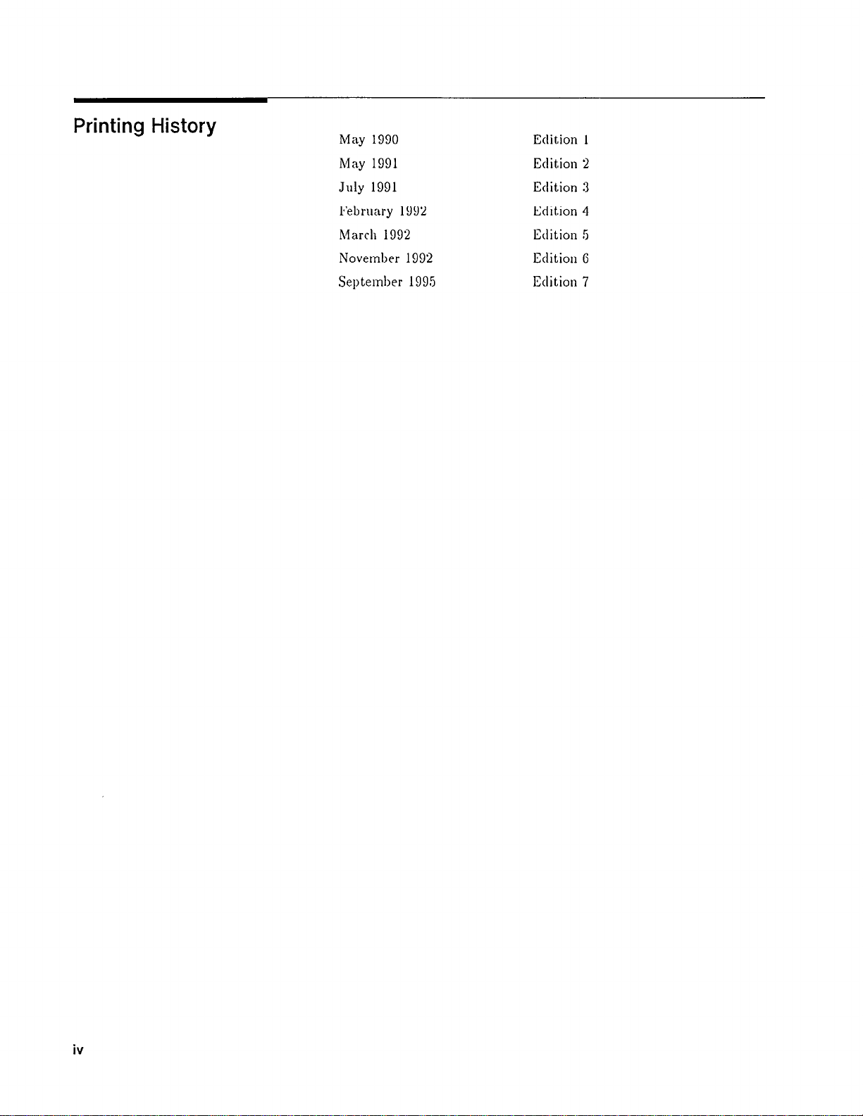
Printing History
May 1990
May 1991
July 1991
February 1992
March 1992
November 1992
September 1995
Edition 1
Edition 2
Edition 3
Edition 4
Edition 5
Edition 6
Edition 7
iv
Page 5
Safety Summary
Safety Symbols Marked
on the Cardiograph
Conventions Used in
This Manual
Caution
Note ,
8” .
9l?
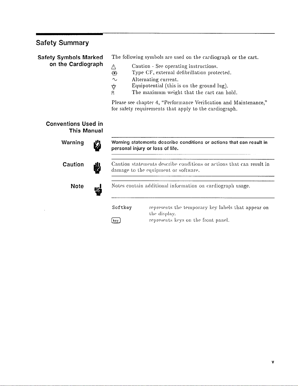
The following syml~ols are used
A
Caution - See operating instructions.
on
the cardiograph or the cart.
ipJk Type CF, externd tlcfil~rillation protected.
Alternating current.
Equipotential (this is on the ground
if
The niaxin1unl weight that the cart can hold.
Please see chapter 4,
“Pcrfomance Verification ant1 Maintenance,”
lug).
for safety requirements that apply to the cardiograph.
Warning statements describe conditions or actions that can result in
personal injury or loss of life.
Ca,ution
tlaitia.gc
Notes couta.in zdditiollal infuonl;I.tioIr
sta?.Lci~rc~~~Ls
Lo
LIIC 0qrtip111enL or sol’t~v;\w.
tlcstrriI)(~
wi~tlitions or actions Ll1a.t can
on
c:artliogra.ph usage.
result in
Sof tkey
a
r~~prwriits Llic> Lrrnpor~lry
Ll~r display.
rcplTsc~llLs
liC’.\iS
011 LllP
I‘I~OIIL
IiCy
lal,l~cls Iliat appear on
pwl.
V
Page 6
Preface
This nlanual contains service information for the Hewlett-Packard
M1700A PageWriter XLi, M1701A PageWriter XLs, and M1702A
PageWriter XLe cardiographs. The informat,ion and procedures in
this nlanual apply to all models unless otherwise specified.
This manual is orgmizetl as follows:
Chapter l-Introduction. Contains a general description of
the cardiographs, lists of technical specifications, and lists of
accessories ant1 options.
Chapter 2-Installation aud Configuration. Snnlmarizes the
cardiograph insta.lla.tion ant1 explains how to Configure the
cardiograph for specific customer requireinents.
Chapter 3-Operation. Suniniarizes how to operate tlie
cardiograph.
Chapter 4-Performance Verification aud Maintenance. Explains
how to CheCli the ca.idiograph’s perforlna.nce using built-in
self-tests, a.ntl lists lnai
nlciln.ncr
procctlurcs a.ntl sa.fety requirements
that apply to llir (~r7rtliogi~aph.
Chapter 5-Theory of Operation.
the cardiogra~pli Works and
sul~assrinl~lies.
tlcscri1)c.i; the opcrn.tion of the major
Provides a.11 overview of how
Chapter 6-Troubleshooting. (:ollta7dns proc-ctlures ant1 err01
codes to aid t;lle srrvicc person in ioca.lizin g faults to ;L repla.ceable
subnsseinbly.
Chapter 7--Removal and Replacement. (~ollt.ains procedures
for
rciuovitlg
snl~assrnil~lics.
Chapter 8-Parts List.
replnwnl)lr
Appendix A-Connector Pin Assignments.
the
signals assig1ird
alit1 wplncing
parts,
antI provitlrs n5srtnl)l.~ tlm.\\:it~gs.
Lo
c:l(.I~ of 1.110 ci~i~tliograpll’s major
Lists
part IIUIII~~I.S for llrc cwliograph’s
Itlc~ltifies and defines
tlio sul~a.ss;e~nl~ly iliLrrColineclions.
Appendix B-M1754A Signal Averaged ECG System. Enables
the ca.rtliograph to
clclwl,
tlisplny, mtl record lii~h-fi,equency,
low-miplitutlr E,(:C; sign&.
Appendix C-M1756A Direct Digital ECG Fax. Pcmits the
PageWriter XLi to rcceivc or lmisniil from fa.x inachnines.
Appendix D-Vectrocardiography M1790A.
Adds
vector loop
repoting ca.pabiliLy to Llie cardiograph.
Index.
vi
Page 7
Contents
Introduction
1.
PageWriter XL Cardiographs
M1705A Cart ................
M1706A/B Telecommunications Package
M1755A A.03.XX Software
A.02.XX Software
A.01.XX Software
Inquiries ...................
Specification Data ...............
Options and Accessories
PageWriter XLi, XLs and XLe Cardiographs
Country Options
Delete Options ...............
Cable Options ...............
Supplies/Accessories Options
Substitute Options
Documentation Options
Standard Accessories Supplied
M1703A PageWriter XLi Upgrade Kits
Options ..................
M1704A PageWriter XLs Upgrade Kits
Options ..................
M1706A Telecommunications Package
Options ..................
M1706B Telecommunications Package
Options ..................
M1753A PageWriter XLe Upgrade Kit
Options ..................
M1754A PageWriter XLi Signal Averaged ECG
System ..................
Documentation Options
M1755A PageWriter XLi Upgrade Kit
M1756A PageWriter XLi Direct Digital ECG Fax
Modems .................
Options ..................
M1788A Extra Patient Module
Options ..................
Substitute Options
M1790A PageWriter XLi Vectorcardiography
Country Option Configurations
..............
..............
.............
..............
.............
.............
..........
..........
........
............
........
...........
.........
.........
.....
.....
......
......
.....
......
....
...
. .
1-1
1-3
1-4
1-4
1-4
1-4
1-4
1-5
1-9
1-9
1-9
1-9
1-9
1-10
1-10
1-10
1-10
1-11
1-11
l-11
l-11
1-11
l-11
1-12
1-12
1-12
1-12
1-12
1-12
1-12
1-13
1-13
1-13
1-13
1-13
1-14
1-14
Contents-1
Page 8
2. Installation and Configuration
Installation ..................
Installing the Cardiograph and Modems on the Cart 2-2
Installing the M1756A Fax Modem ......
Printing an ECG on an HP LaserJet Printer ....
Setting up the LaserJet Printer ..........
Configuring the Cardiograph to Print ECGs on the
HP LaserJet ...............
Connecting the Patient Module ........
Changing the Line Voltage Setting .......
Changing the Line Fuses ...........
Installing the Battery .............
Installing the Software on the M1700 & M1701A .
Installing the Software on the M1702A .....
Loading the Paper .............. 2-14
Setting the Date and Time ..........
Configuration .................
Configuring the M1700A and M1701A .....
Configuring the M1702A ...........
Selecting Configuration Parameters .......
Global Configuration ............. 2-20
Interpretation Parameters .......... 2-24
Power-on Application (M1755A A.02.X); and
Higher Software Only) .......... 2-24
Line Frequency ............... 2-24
Custom Lead Groups ............ 2-25
AutoCopy ................. 2-25
ECG Management Parameters ........ 2-26
Battery Timeout, .............. 2-26
Password ................. 2-26
ID Configuration ............... 2-27
Transmit Configuration ............ 2-28
Transmit ................. 2-28
Entering the Phone Number ........ 2-29
Receive .................. 2-30
AutoDial ................. 2-30
LaserJet Printer Configuration (A.03.XX Software
Only) .................. 2-31
Configuration Files .............. 2-31
Store ................... 2-31
Print
................... 2-32
2-1
2-2
2-4
2-5
2-6
2-7
2-8
2-10
2-11
2-13
2-14
2-16
2-17
2-17
2-18
2-19
Contents-2
Page 9
3. Operation
The Keyboard and Front Panel
Other Operating Controls
Choosing a Report Format
Main Functions
................
Transmit (M1700A Only)
Store (M1700A & M1701A only)
Config
...................
CheckDisk (M1700A & M1701A only)
A.01.XX Software
.............
A.02.XX and Higher Software
Files (M1700A & M1701A only)
.........
...........
...........
...........
........
......
........
........
The Selection Display (M1700A & M1701A only) .
Selection Display Menu, Part 1
Selection Display Menu, Part 2
Recording an ECG
...............
Using the Patient Module Start Button
........
........
.....
Preview Plus (A.02.XX and Higher Software Only) .
Using Preview Plus
..............
4. Performance Verification and Maintenance
Introduction
Performance Verification
Visual Inspection
Extended Self-test
Patient Module and Cable Test
CPU Assembly Test
Printer Test
..................
............
...............
..............
.......
............
................
Disk Drive Test (M1700A and M1701A only) . .
Preview Display Test (M1700A Only)
Keyboard Display Test
...........
Modem Test (M1700A Only)
All Tests
Printing the Error Log
ECG Simulation
Preventive Maintenance
Care and Cleaning
.................
...........
...............
..............
..............
.........
.....
Cleaning the Cardiograph and Patient Module .
Cleaning the Keyboard
...........
Cleaning the Printhead and Paper Sensor
Maintaining the Flexible Disk Drive
.....
Cleaning the Electrodes, Leadwires, and Patient
Data Cable ...............
Safety Tests
..................
PageWriter XL Performance Verification Checklist . .
Visual Inspection
Extended Self-test
ECG Simulation
Comments:
...............
..............
...............
.................
...
3-2
3-3
3-4
3-10
3-11
3-12
3-12
3-12
3-12
3-12
3-13
3-15
3-15
3-15
3-16
3-17
3-17
3-17
4-1
4-1
4-1
4-2
4-3
4-3
4-4
4-4
4-5
4-6
4-6
4-7
4-7
4-8
4-9
4-10
4-10
4-10
4-11
4-12
4-13
4-13
4-14
4-14
4-14
4-15
4-15
Contents-3
Page 10
5. Theory of Operation
Operational Overview
.............. 5-1
ECG Data Path ............... 5-1
Power-on and Power-off Sequences
Power-on .................
Power-off ................. 5-2
Circuit Descriptions
..............
The Standard Patient Module
CPU Assembly
.................
CPU .................... 5-8
System Memory ............... 5-10
ROM .................... 5-10
I/O Control .................
The FGA .................
Serial Communications
Digital Signal Processor
............
System Expansion Connector
Disk Drive (M1700A and M1701A only)
Power Supply
................. 5-16
VMAIN and VIN ...............
Battery Charger and Battery Sensor
Battery Operation and Condition
5 Volt Regulator ............... 5-19
+5 Overvoltage/Undervoltage Sensor
Printer Switch ................
Battery Switch ................
ACON Detector ...............
+5 Backup Supply and Low Battery Disconnect . .
+5 to Backup Switchover
Patient Module Voltage Regulator
The Keyboard and Keyboard Display
Printer
....................
Printer Gate Array ..............
Printer RAM ................
Motor Driver ................
ADC (Analog-to-Digital Converter)
Thermal Printhead ..............
The Preview Display
..............
Preview Logic Board .............
Preview Display Power Supply Board
VLCD Supply ...............
VCFL Supply ...............
Preview Screen ................
.......
5-2
5-2
5-4
..........
5-6
5-8
5-12
5-12
........... 5-14
5-14
.........
.....
5-15
5-15
5-16
......
.......
5-18
5-18
...... 5-19
5-20
5-20
5-20
5-21
...........
.......
.......
5-21
5-21
5-22
5-22
5-22
5-22
5-22
.......
5-23
5-23
5-24
5-25
...... 5-26
5-27
5-27
5-27
Contents-4
Page 11
6. Troubleshooting
Introduction ..................
Maintenance Philosophy
Test Equipment
The Error Log
................
.................
Clearing the Log
.............
...............
Errors ....................
Using Extended Self-test in Troubleshooting
Troubleshooting Tables
Testing the Power Supply
.............
...........
7. Removal and Replacement
Introduction
Tool Requirements
The Battery
Removing the Battery
Replacing the Battery
..................
..............
..................
.............
.............
The Keyboard and the User Interface Assembly . . .
The Keyboard
The User Interface Assembly
................
..........
Removing the User Interface Assembly
Replacing the User Interface Assembly
The Printer Drive Assembly
Removing the Printer Drive Assembly
...........
......
PageWriters with Serial Number Prefix 3208A or
Later
.................
PageWriters with Serial Number Prefix Prior to
3208A
Replacing the Printer Drive Assembly
The Preview Screen Assembly
Removing the Preview Screen Assembly
.................
......
..........
.....
PageWriters with Serial Number Prefix 3208A or
Later
.................
Removing the Entire Preview Screen Assembly
Disassembling the Preview Screen Assembly .
PageWriters with Serial Number Prefix Prior to
3208A
.................
Removing the Entire Preview Screen Assembly
Disassembling the Preview Screen Assembly .
Replacing the Preview Screen Assembly
The Top Cover Assembly
............
.....
Opening and Removing the Top Cover Assembly .
PageWriters with Serial Number Prefix 3208A or
Later
.................
PageWriters with Serial Number Prefix Prior to
3208A
Reinstalling the Top Cover Assembly
The Printhead Assembly
Removing the Printhead Assembly
.................
......
............
.......
PageWriters with Serial Number Prefix 3208A or
Later
.................
....
....
....
6-1
6-1
6-1
6-2
6-2
6-3
6-4
6-5
6-22
7-1
7-2
7-2
7-2
7-4
7-5
7-5
7-5
7-5
7-6
7-7
7-7
7-7
7-9
7-11
7-12
7-12
7-12
7-12
7-13
7-15
7-15
7-15
7-17
7-17
7-17
7-17
7-19
7-20
7-20
7-20
7-20
Contents-5
Page 12
PageWriters with Serial Number Prefix Prior to
3208A .................
Removing the Optical Paper Sensor
Replacing the Printhead Assembly
The Preview Logic Board
............
Removing the Preview Logic Board
PageWriters with Serial Number Prefix 3208A or
Later .................
PageWriters with Serial Number Prefix Prior to
3208A .................
Replacing the Preview Logic Board
The CPU Assembly ...............
Removing the CPU Assembly
Replacing the CPU Assembly
.........
.........
The Disk Drive (M1700A and M1701A only)
Replacing the Disk Drive
...........
8. Parts Lists
Introduction ..................
Ordering Information ..............
Calling for Assistance ..............
United States of America
...........
Canada ...................
.......
.......
.......
.....
....
7-21
7-23
7-23
7-25
7-25
7-25
7-27
7-28
7-29
7-29
7-31
7-31
7-32
8-1
8-1
8-1
8-1
8-1
A. Connector Pin Assignments
CPU Assembly Connectors
Preview Display Connectors
...........
...........
B. M1754A Signal Averaged ECG (SAECG) System
Introduction ..................
Installation and Configuration
Connecting the Patient Module
Installing the SAECG Software
..........
........
.........
SAECG Configuration (A.02.XX and higher Software
Only) ..................
Acquisition Fields .............
Measurement Fields
............
Operation ...................
SAECG (M1754A Only)
............
Using SAECG ................
Editing and Printing a Stored SAECG
Deleting a Stored SAECG
...........
Performance Verification and Maintenance
....
.....
Extended Self-test ..............
Patient Module and Cable Test
.......
Theory of Operation ..............
The SAECG Patient Module
..........
Troubleshooting ................
Parts List ...................
A-1
A-11
B-1
B-2
B-2
B-3
B-4
B-4
B-5
B-6
B-6
B-7
B-10
B-10
B-11
B-11
B-12
B-13
B-13
B-15
B-16
Contents-6
Page 13
M1756A Direct Digital ECG Fax
C.
Introduction
Installation and Configuration
Operation
Transmitting ECGs by Fax
..................
..........
...................
..........
Transmitting More than One ECG
Receiving ECGs
...............
Performance Verification and Maintenance .....
Extended Self-test
..............
Fax Modem Test (M1700A Only)
Troubleshooting
Parts List
...................
................
D. Vectorcardiography M1790A
Introduction
Installation and Configuration
..................
..........
Setting Up the Patient Module ........
Software Installation
.............
VCG Configuration (A.03.XX Software Only) . .
Disabling VCG Reports
Operation
...................
Recording a VCG
Printing a Stored VCG
............
..............
............
Preventing the VCG Report from Printing
The VCG Report
VCG Report Formats
Formats
..................
Manual Report Formats
Troubleshooting
Parts List
...................
...............
.............
...........
................
......
.......
....
C-1
C-2
C-3
C-3
C-4
C-4
C-5
C-5
C-6
C-7
C-8
D-l
D-2
D-2
D-3
D-3
D-4
D-4
D-4
D-5
D-5
D-6
D-7
D-7
D-10
D-10
D-12
Index
Contents-7
Page 14
Figures
1-1. M1700A PageWriter XLi Cardiograph with Preview
Display.
2-1. Installing the Hayes® Modem.
2-2. Connecting the Fax Modem Cables.
2-3. Connecting the Printer Cable.
2-4. Connecting the Patient Module.
2-5. The Line Module and AC Switch.
2-6. Installing the Battery. .............
2-7. Fitting the Battery Holder Tab Into the Battery Slot.
2-8. Loading the Paper. ..............
3-1. The Keyboard and Front Panel.
3-2. An Auto 3x4 ECG (3x4).
3-3. An Auto 3x4 ECG With Three Rhythm Strips (3x4,
3R). ...................
3-4. A Manual 6-Lead ECG.
3-5. An SAECG Report. .............
4-1. 12-Lead ECG from ECG Simulator.
4-2. Cleaning the Digital Array Printhead.
5-1. CPU Initialization Flow Chart.
5-2. Simplified System Block Diagram.
5-3. Patient Module Block Diagram.
5-4. CPU Assembly Block Diagram.
5-5. System Memory Block Diagram.
5-6. I/O Control Block Diagram.
5-7. Serial Communications Circuitry.
5-8. Digital Signal Processor Block Diagram.
5-9. The Disk Drive and its Control Circuit.
5-10. Power Supply Block Diagram.
5-11. Printer Block Diagram.
5-12. Preview Display Subassembly Connections.
5-13. Preview Logic Board Block Diagram.
5-14. Preview Display Power Supply Block Diagram.
6-1. Sample Error Log Printout.
6-2. Troubleshooting Flowchart.
6-3. Voltage Test Locations.
7-1. Opening the Battery Compartment.
7-2. Fitting the Battery Holder Tab Into the Battery Slot.
7-3. Removing the Keyboard.
7-4. User Interface Screw Locations.
7-5. Removing the Printhead Cover.
7-6. Printer Drive and Keyboard Ground Plane Screw
Locations. ................
.................
.........
.......
.........
........
.......
........
...........
............
.......
......
.........
.......
........
........
........
...........
........
.....
.....
.........
............
...
......
..
..........
..........
............
......
...........
........
........
1-2
2-2
2-3
2-4
2-7
2-8
2-11
2-12
2-15
3-2
3-6
3-7
3-8
3-9
4-8
4-11
5-3
5-5
5-7
5-9
5-11
5-13
5-14
5-15
5-15
5-17
5-23
5-24
5-25
5-27
6-3
G-G
6-24
7-3
7-4
7-5
7-6
7-7
7-8
Contents-8
Page 15
7-7. Removing the Printhead Cover.
........
7-8. Printer Drive and Keyboard Ground Plane Screw
Locations.
7-9. The Printer Drive Gears.
................
...........
7-10. Opening and Removing the Top Cover Assembly. .
7-11. Removing the Preview Screen Assembly.
7-12. Removing the Preview Screen Assembly.
.....
.....
7-13. Opening and Removing the Top Cover Assembly. .
7-14. Opening and Removing the Top Cover Assembly. .
7-15. Removing the Printhead Cover and Printhead.
7-16. Removing the Printhead Cover and Printhead.
7-17. Printhead Resistance Selector.
.........
..
..
7-18. Preview Logic Board Removal (Serial Number Prefix
3208A or Later).
.............
7-19. Preview Logic Board Assembly Screw Locations. .
7-20. Screw and Connector Locations on the CPU
Assembly.
7-21. Disk Drive Mounting Screws.
8-1. Patient Module Diagram.
................
.........
...........
8-2. Main Assembly Exploded Diagram (Serial Number
Prefix 3208A or Later).
..........
8-3. Main Assembly Exploded Diagram (Serial Number
Prefix Prior to 3208A).
8-4. Printer Assembly Diagram.
8-5. Preview Display Assembly Diagram.
8-6. Cart Exploded Diagram.
8-7. Cart Exploded Diagram.
8-8. Data Communications Package Diagram.
8-9. Connections for Direct-Connect Transmission
8-10. Cabling for Hayes Modem Transmission Only
...........
..........
......
...........
...........
....
. .
. .
8-11. Cabling for Hayes Modem and Direct Connect (Quick
Connect) Transmission
8-12. Cabling for LaserJet Printing
B-1. Connecting the Patient Module.
B-2. An SAECG Report.
B-3. A Template Screen.
..............
B-4. SAECG Patient Module Block Diagram.
C-1. Cabling for FAX Modem Transmission Only
...........
.........
........
.............
....
...
C-2. Cabling for FAX Modem and Direct Connect (Quick
Connect) Transmission
D-1. The VCG Report
...............
D-2. VCG1: Right Sagittal, 0° to 360°.
D-3. VCG2: Left Sagittal, 0° to 360°.
D-4. VCG3: Right Sagittal, -180° to +180°.
D-5. VCG4: Left Sagittal, -180° to +180°.
...........
.......
........
.....
......
7-9
7-10
7-11
7-13
7-14
7-16
7-18
7-19
7-21
7-22
7-24
7-26
7-28
7-30
7-32
8-2
8-4
8-9
8-15
8-17
8-19
8-21
8-23
8-24
8-25
8-26
8-27
B-2
B-6
B-8
B-14
C-9
C-10
D-6
D-7
D-8
D-8
D-9
Contents-9
Page 16
Tables
1-1. Physical Specifications
1-2. Patient Module Specifications
1-3. SAECG Patient Module Specifications
1-4. ECG to Paper Specifications
1-5. Power Supply and Battery Specifications
1-6. Environmental Specifications
1-7. Miscellaneous Specifications
1-8. Country Option Configurations
2-1. Line Voltage Settings .............
2-2. Line Fuse Ratings for Voltage Settings
2-3. Global Configuration Parameters
2-4. Global Configuration Parameters (continued)
2-5. Global Configuration Parameters (continued)
2-6. Site Transmission Configuration
2-7. Site Receive Configuration
2-8. LaserJet Printer Configuration
6-1. Power-on Errors ...............
6-2. Power Supply and Battery
6-3. Patient Module and Patient Data Cable
6-4. CPU Assembly (CPU, FGA, ROM, RAM)
6-5. Printer ...................
6-6. Disk Drive (M1700A and M1701A only)
6-7. Preview Display and Logic (M1700A)
6-8. Keyboard and Keyboard Display (LCD)
6-9. Transmit and Modem .............
7-1. Printhead Resistance Codes
8-1. Patient Module Parts List
8-2. Main Assembly Parts List (Serial Number Prefix
3208A or Later) ..............
8-3. Main Assembly Parts List (Serial Number Prefix
Prior to 3208A) ..............
8-4. Fastener List .................
8-5. Printer Parts List ..............
8-6. Preview Display Assembly Parts List
8-7. Cart Parts List ................
8-8. Cart Fastener List ..............
8-9. M1705B Cart Parts List
8-10. Data Communications Package Parts List
8-11. Direct Connect Cable Parts List
8-12. Hayes Modem Cable Parts List
8-13. Hayes Modem and Direct Connect Cables Parts List
8-14. LaserJet Cable Parts List
............
.........
.....
..........
....
..........
..........
.........
.....
........
. .
. .
........
...........
.........
...........
.....
....
.....
......
.....
..........
...........
......
............
....
........
.........
...........
1-5
1-5
1-6
1-6
1-7
1-8
1-8
1-14
2-9
2-9
2-20
2-22
2-23
2-29
2-30
2-31
6-8
6-9
6-12
6-14
6-15
6-17
6-19
6-20
6-21
7-23
8-3
8-5
8-10
8-14
8-16
8-18
8-20
8-20
8-22
8-23
8-24
8-25
8-26
8-27
Contents-10
Page 17
A-1. Keyboard and Keyboard Display (LCD) Connector
J1....................
A-2. Printhead Logic Connector J2
A-3. Printer Motor and Sensor Connector J3
A-4. Battery Connector J4
.............
A-5. Printhead Power Connector J5
A-6. Patient Module Connector J9
A-7. RS-232 Connector J10
............
A-8. System Expansion Connector J12
A-9. Disk Power Connector J14
A-10. Disk Drive Logic Connector J15
.........
.....
.........
.........
........
...........
........
A-11. Preview Display Logic Board, J1, to Preview Display
Power Supply Board, J2
A-12. Power Supply to LCD Module, J1
A-13. Power Supply to LCD Module, 52
B-1. Acquisition Configuration Fields
..........
.......
.......
........
B-2. Measurement/Processing Configuration Fields . .
B-3. SAECG Testing Problems
B-4. Patient Module and Patient Data Cable
B-5. SAECG Parts List
C-1. Transmit and Fax
...............
..............
C-2. Fax Modem Parts List
C-3. Fax Modem Cable Parts List
...........
.....
............
..........
C-4. Fax Modem and Quick Connect Cable Parts List .
D-1. AHA Lead Set and Patient Module Configurations
D-2. IEC Lead Set and Patient Module
D-3. Global Configuration Fields
D-4. VCG Report Formats
D-5. Troubleshooting
D-6. VCG Parts List
.............
...............
...............
..........
.......
A-2
A-3
A-4
A-5
A-5
A-6
A-7
A-8
A-9
A-10
A-11
A-12
A-12
B-4
B-5
B-15
B-15
B-16
C-7
C-8
C-9
C-10
D-2
D-2
D-4
D-7
D-10
D-12
Contents-11
Page 18
Introduction
1
This chapter introduces you to the M1700A PageWriter XLi,
M1701A PageWriter XLs, and M1702A PageWriter XLe cardiographs
and lists their technical specifications.
Warning
Note
These cardiographs are only to be serviced by qualified personnel.
Safe and effective use of medical instrumentation requires periodic
inspection and preventive maintenance. Perform the preventive
maintenance procedures in Chapter 4 of this manual at required
intervals to ensure satisfactory instrument performance.
The cardiographs use a thermal printhead to record waveforms and
label the ECG report. The paper supplied with the cardiographs is a
special thermal paper designed specifically to work with the thermal
printhead and the photo detector used to advance the paper.
The cardiograph’s clisk drive (M1700A & M1701A only) is a critical
part. Disks of substandard quality can damage the clrive or destroy
patient clata.
Hewlett-Packarcl guarantees the performance of the cardiographs only
when used with paper and disks that meet or exceed Hewlett-Packard
specifications.
PageWriter XL Cardiographs
The M1700A PageWriter XLi is Hewlett-Packard’s full-featured,
interpretive cardiograph. The M1701A PageWriter XLs is the
standard, non-interpretive cardiograph. The M1702A PageWriter
XLe is the basic, non-interpretive cardiograph. Each cardiograph
uses a patient module, which is a remote “front end” that acquires
and digitizes clata. The M1700A and M1701A patient modules
feature a start button ant1 an LCD display that indicates signal
quality. The M1702A patient module does not feature a display
or start button. The cardiograph main unit has the user controls,
the disk drive (M1700A and M1701A only), the printer, and all the
processing circuitry. All models use the same enclosure, except when
the h41700A is equipped with preview display. The models fit onto
the M1705A cart clesignecl for these carcliographs. Figure l-1 shows
the M1700A with preview display mounted
on
the cart.
Introduction l-l
Page 19
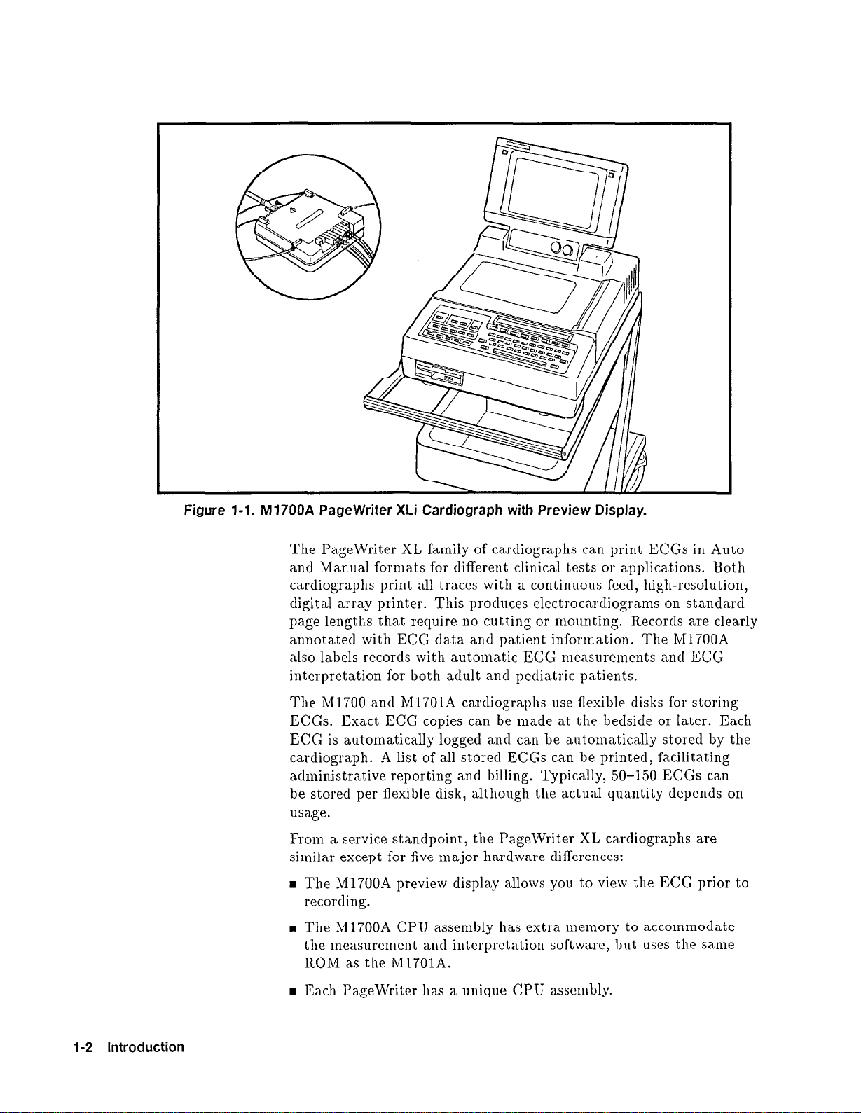
Figure l-l. M1700A PageWriter XLi Cardiograph with Preview Display.
The PageWriter XL family of cardiographs can print ECGs in Auto
and Manual formats for different clinical tests or applications. Both
cardiographs print all traces with a continuous feed, high-resolution,
digital array printer. This produces electrocardiograms on standard
page lengths that require
no
cutting or mounting. Records are clearly
annotated with ECG data and patient information. The M1700A
also labels records with automatic ECG measurements and ECG
interpretation for both adult and pediatric patients.
The Ml700 ant1 M1701A cardiographs use flexible disks for storing
ECGs. Exact ECG copies can be made at the bedside or Iater. Each
ECG is automatically logged and can be automatically stored by the
cardiograph. A list of all stored ECGs can be printed, facilitating
administrative reporting and billing. Typically, 50-150 ECGS can
be stored per flexible disk, although the actual quantity depends on
usage.
From a service standpoint, the PageWriter XL cardiographs are
similar except for five major hardware differences:
H The h41700A preview display allows you to view the ECG prior to
recording.
1-2 Introduction
n
The M1700A CPU assembly has extra nlenlory to accommodate
the measurement and interpretation software, but uses the same
ROM as the M1701A.
n
Each PageWriter has a unique CPU asscnibly.
Page 20
n
The M1700A and M1701A load software from, and store ECGs to,
the disk drive. The M1702A software is in ROM, and does not
store ECGs.
n
The M1700A and M1701A patient modules feature a display that
indicates signal quality and a start button. The M1702A patient
module does not offer these features.
All other model differences are found in the cardiograph’s software.
The M1700A and M1701A software is installed in the cardiograph
from flexible disk, while the M1702A software is installed from ROM.
After installation, the software is stored in dynamic RAM (DRAM).
Re-installation is required only when a user desires a different
configuration, or if DRAM loses its contents due to a low battery.
The PageWriter XL family of cardiographs is designed for long-term
reliability. The modular clesign makes extensive use of VLSI and
gate array technology, resulting in a minimum number of major
subassemblies. The modular approach means less down-time for the
user, since replacing subassemblies allows quicker field repairs. The extended self-test efficiently identifies faulty subassemblies, further
speeding the repair process.
Note
:’
t?
M1705A Cart
As of February 1992, all new PageWriter XL cardiographs are
manufactured to a revised mechanical design specification. All units
having a serial number prefix of 3208A or later conform to this
revised specification. This manual describes all specific differences.
The following paragraphs describe some of the significant options
available for the PageWriter XL cardiographs.
The M1705A Cart provides mobility for the PageWriter XL family
of cardiographs. The large wheels make the cart easy to move, yet
steady when in use. Slots in the cardiograph’s feet and a thumbscrew
secure the cardiograph to the cart rails, The tray directly below the
cardiograph provides storage for acquired ECGs, the user’s guide,
and several flexible disks. The tray also has molded fittings that
accommodate the modem in the M170GA/B Telecommunications
Package. Storage for the power cable is built in, and other built-in
cable retainers hold the patient clata cable out of the way. Two
compartmented trays provide storage for the patient module,
spare patient electrodes and leaclwires, additional thermal paper,
consumable supplies, and miscellaneous items. An optional paper
management tray is also available for the M1705A.
Introduction 1-3
Page 21
M1706A/B
Telecommunications
Package
With the addition of the M1706A or M1706B Telecommunications
Package, the M1700A can transmit ECGs over telephone lines to
another site. The receiver at the other site can be a Hewlett-Packard
ECG Management system or another M1700A. This feature is not
available for the M1701A.
The M1706A or M1706B Telecommunications Package consists
of a Hayes@ modem, a bracket that attaches the modem to the
cart, a power cable that connects to the modem power outlet on
the cardiograph, and data cables that connect the modem to the
cardiograph and the telephone system. Local laws, regulations, and
phone system standards determine the specific type of modem and
accessories included and the types of cables included in the M1706A
or M1706B Telecommunications Package.
M1755A A.03.XX
A.02.XX Software
A.01 .Xx Software
Inquiries
Software
This software is shipped with PageWriter XLi on a standard basis.
This revision provides the PageWriter XLi with severity-only
analysis, LaserJet printing option, and extended configurable
transmission phone numbers. This revision includes all A.02.XX
enhancements and also provides fax transmission, SAECG, and VCG
capabilities. The software is shipped with all new PageWriter XLi
cardiographs in late 1992.
This software revision provides the PageWriter XLi with enhanced
preview displays, interactive query, and FAA transmission. The
software also gives the XLi fax transmission using the M175GA
modem and SAECG capabilities. This revision is only available for
support purposes.
The original software for PageWriter XLi provides all basic features
with preview display. This revision is only available for support
purposes.
Refer any questions or comments regarding these instruments
to the nearest Hewlett-Packard Sales/Service Office or to one of
Hewlett-Packard’s Service Dispatch Centers. They can provide
you with additional information about service training, special
applications, and schematics. Always identify the instrument
by model number and serial number in all correspondence.
Hewlett-Packard sales and service offices are listed at the end of this
manual. Toll-free numbers for Service Dispatch Centers are listecl in
Chapter 8, “Parts List.”
1-4 Introduction
Page 22
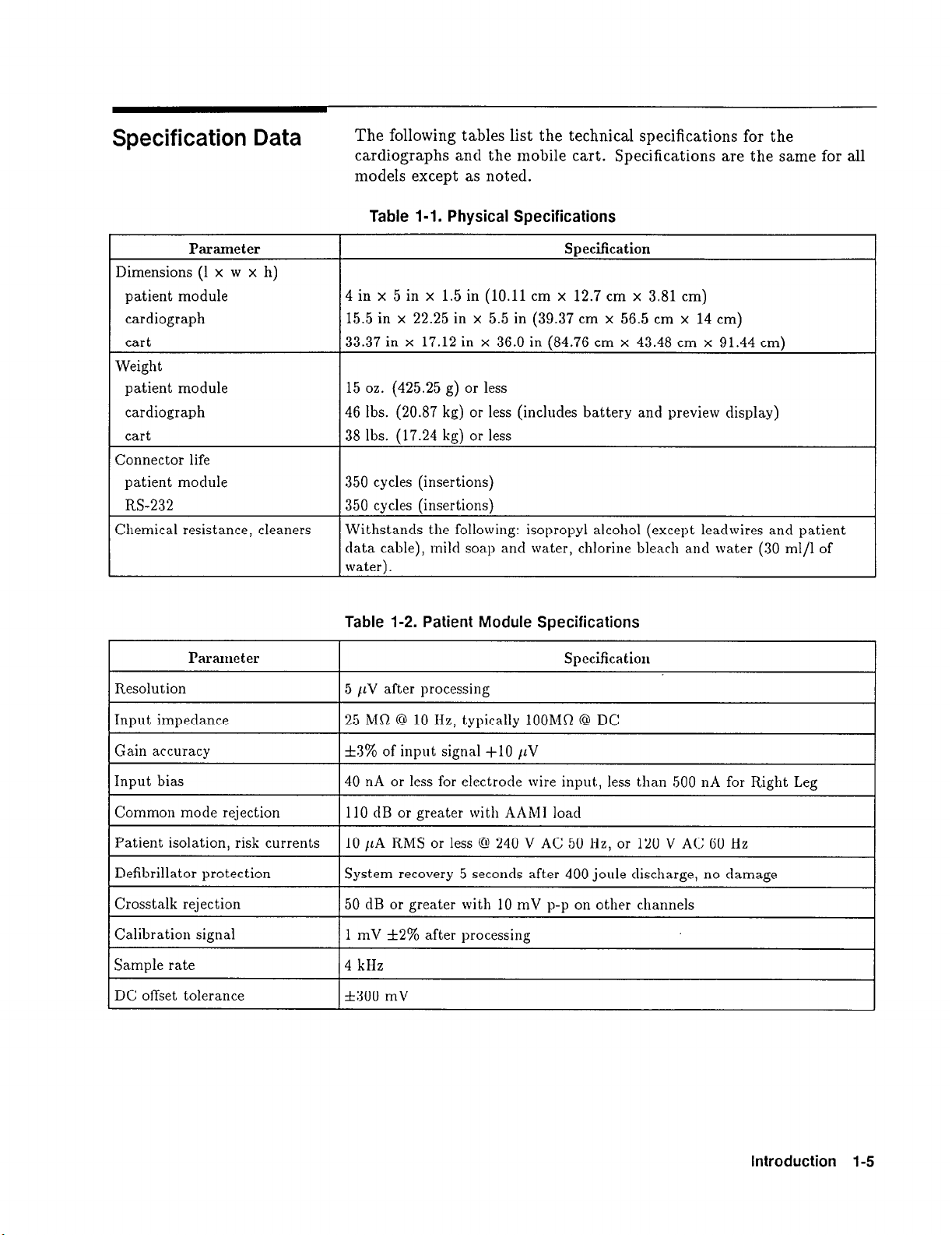
Specification Data
The following tables list the technical specifications for the
cardiographs and the mobile cart. Specifications are the same for all
models except as noted.
Table 1-1. Physical Specifications
Parameter
Dimensions (1 x w x h)
patient module
cardiograph
cart
Weight
patient module
cardiograph
cart
Connector life
patient module
RS-232
Chemical resistance, cleaners
Parameter Specification
Resolution 5 /iv after processing
4 in x 5 in x 1.5 in (10.11 cm x 12.7
15.5 in x 22.25 in x 5.5 in (39.37 cm
33.37 in x 17.12 in x 36.0 in (84.76 cm x 43.48 cm x 91.44 cm)
15 oz. (425.25 g) or less
46 lbs. (20.87 kg) or less (includes battery and preview display)
38 lbs. (17.24 kg) or less
350 cycles (insertions)
350 cycles (insertions)
Withstands the following: isopropyl alcohol (except. leadwires and patient
data cable), mild soap and water, chlorine bleach and water (30 ml/l of
water).
Table 1-2. Patient Module Specifications
SDecification
cm x 3.81 cm)
x
56.5 cm x 14 cm)
I
Input impedance
Gain accuracy
Input bias 40 nA or less for electrode wire input, less than 500 nA for Right Leg
Patient isolation, risk currents
Defibrillator protection
Crosstalk rejection 50 dB or greater with 10 mV p-p on other channels
Calibration signal 1 mV f2% after processing
DC offset tolerance
25 MSt @ 10 Hz, typically 1OOMQ @ DC
f3% of
110 dB or greater with AAMI load Common mode rejection
10 pA RMS or less @ 240 V AC 50 Hz, or 120 V AC 60 Hz
System recovery 5 seconds after 400 joule discharge, no damage
4 kHz Sample rate
*300 mV
input
signal +lO ILV
Introduction l-5
I
Page 23
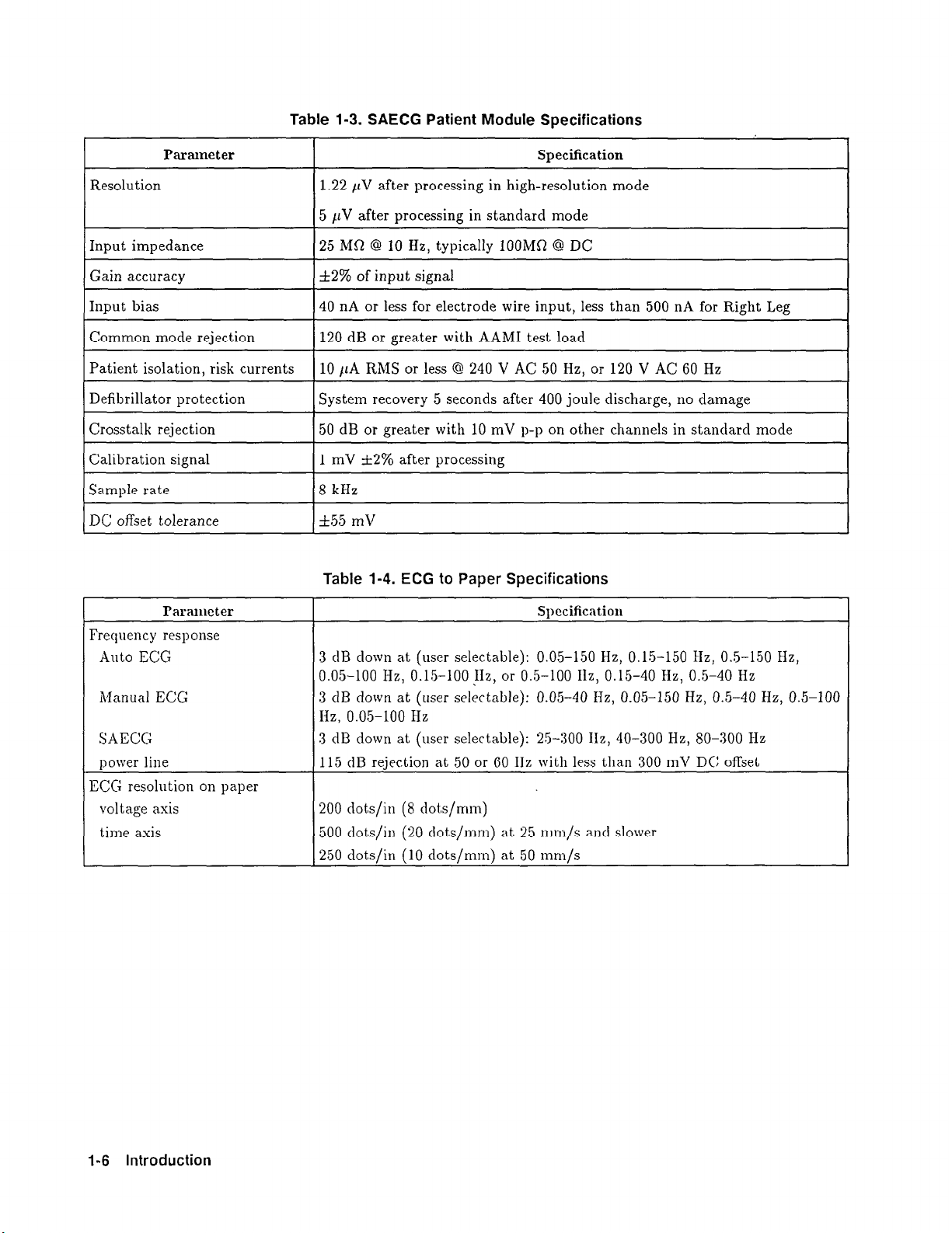
Table 1-3. SAECG Patient Module Specifications
Parameter
Resolution
Input impedance
Gain accuracy
Input bias
Common mode rejection
Patient isolation risk currents
I,--
Crosstalk rejection
I
Calibration signal
Sample rate
DC offset tolerance
Specification
1.22 /IV after processing in high-resolution mode
5 /IV after processing in standard mode
25 MR @ 10 Hz, typically 1OOMfi @ DC
&2% of input signal
] 40 nA or less for electrode wire input, less than 500 nA for Right Leg
120 dB or greater with AAMI test load
10 ItA RMS
System recovery 5 seconds after 400 joule discharge, no damage
50 dB or greater with 10 mV p-p on other channels in standarcl mode
I
1 mV f2% after processing
8 kHz
I
355 mV
Table 1-4. ECG to Paper Specifications
or less @ 240 V AC 50 Hz,
or 120 V AC 60 Hz
I
I
Paranwter
Frequency response
Auto ECG
Manual ECG
SAECG
power line
ECG resolution on paper
voltage axis
time axis
Swxificatiolk
3 dB down at (user selectable): 0.05-150 Hz, 0.15-150 Hz, 0.5-150 Hz,
0.05-100 Hz, 0.15-100 IIz, or 0.5-100 Ilz, 0.15-40 Hz, 0.5-40 Hz
3 dB down at (user selectable): 0.05-40 Hz, 0.05-150 Hz, 0.5-40 Hz, 0.5-100
Hz, 0.05-100 Hz
3 dB down at (user selectable): 25-300 IIz, 40-300 Hz, SO-300 Hz
115 dB rejection at 50 or 60 11s with less than 300 mV DC offset
200 dots/in (8 dok/mm)
500 dots/in (20 dots/mm) at 25 mm/s and slower
250 dots/in (10 dots/mm) at 50 mm/s
1-6 Introduction
Page 24
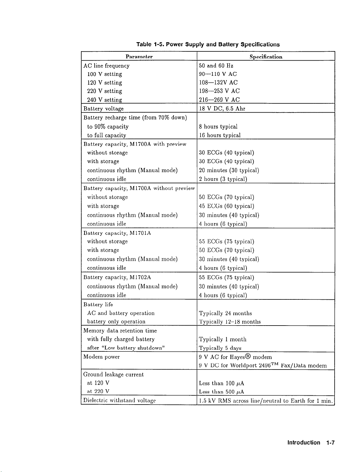
Table 1-5. Power Supply and Battery Specifications
Parameter
AC line frequency
100 V setting
120 V setting
220 V setting
240 V setting
Battery voltage
50 and 60 Hz
90-110 V AC
108-132V AC
198-253 V AC
216-269 V AC
18 V DC, 6.5 Ahr
Specification
Battery recharge time (from 70% down)
to 90% capacity
to full capacity
8 hours typical
16 hours typical
Battery capacity, M1700A with preview
without storage
with storage
continuous rhythm (Manual mode)
continuous idle
30 ECGs (40 typical)
30 ECGs (40 typical)
20 minutes (30 typical)
2 hours (3 typical)
Battery capacity, M1700A without preview
without storage
with storage
continuous rhythm (Manual mode)
continuous idle
50 ECGs (70 typical)
45 ECGs (60 typical)
30 minutes (40 typical)
4 hours (6 typical)
Battery capacity, M1701A
without storage
with storage
continuous rhythm (Manual mode)
continuous idle
Battery capacity, M 1702A
continuous rhythm (Manual mode)
continuous idle
55 ECGs (75 typical)
50 ECGs (70 typical)
30 minutes (40 typical)
4 hours (6 typical)
55 ECGs (75 typical)
30 minut,es (40 typical)
4 hours (6 typical)
Battery life
AC and battery operation
battery only operation
Typically 24 months
Typically 12-18 months
Memory data retention time
with fully charged battery
after “Low battery shutdown”
h/Iodem power
Typically 1 month
Typically 5 days
9 V AC for Hayes@ modem
9 V DC for Worldport 249BTM Fax/Data modem
Ground leakage current,
at 120 V Less than 100 /iA
at 220 V Less than 500 /LA
Dielectric withstand voltage 1.5 kV RMS across line/neutral to Earth for 1 min
Introduction l-7
Page 25
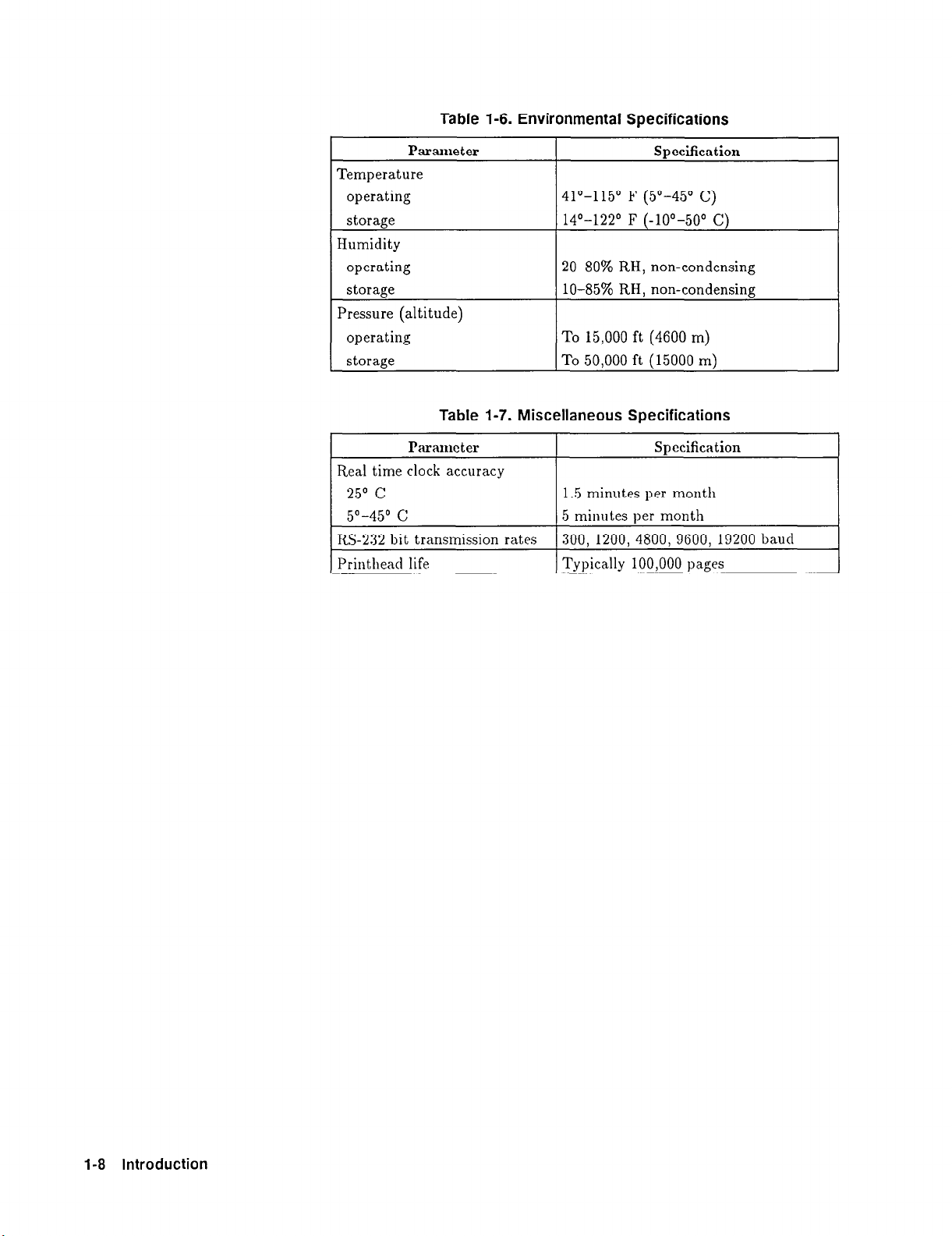
Table 1-6. Environmental Specifications
Parameter
Specification
Temperature
operating
storage
41°-115’ F (5’-45’ C)
14O-122’ F (-lo”-50’ Cj
Humidity
operating
storage
20-80% RH, non-condensing
lo-85% RH, non-condensing
Pressure (altitude)
operating
storage
To 15,000 ft (4600 m)
To 50.000 ft (15000 rnJ
Table 1-7. Miscellaneous Specifications
Parameter
I
Specification
Real time clock accuracy
25’ C
5”-45O c
1.5 minutes per month
5 minutes per month
RS-232 bit transmission rates 300, 1200, 4800, 9600, 19200 baud
Printhead life Typically 100,000 pages
I
1-8 Introduction
Page 26
Options and Accessories
PageWriter XLi, XLs
and XLe Cardiographs
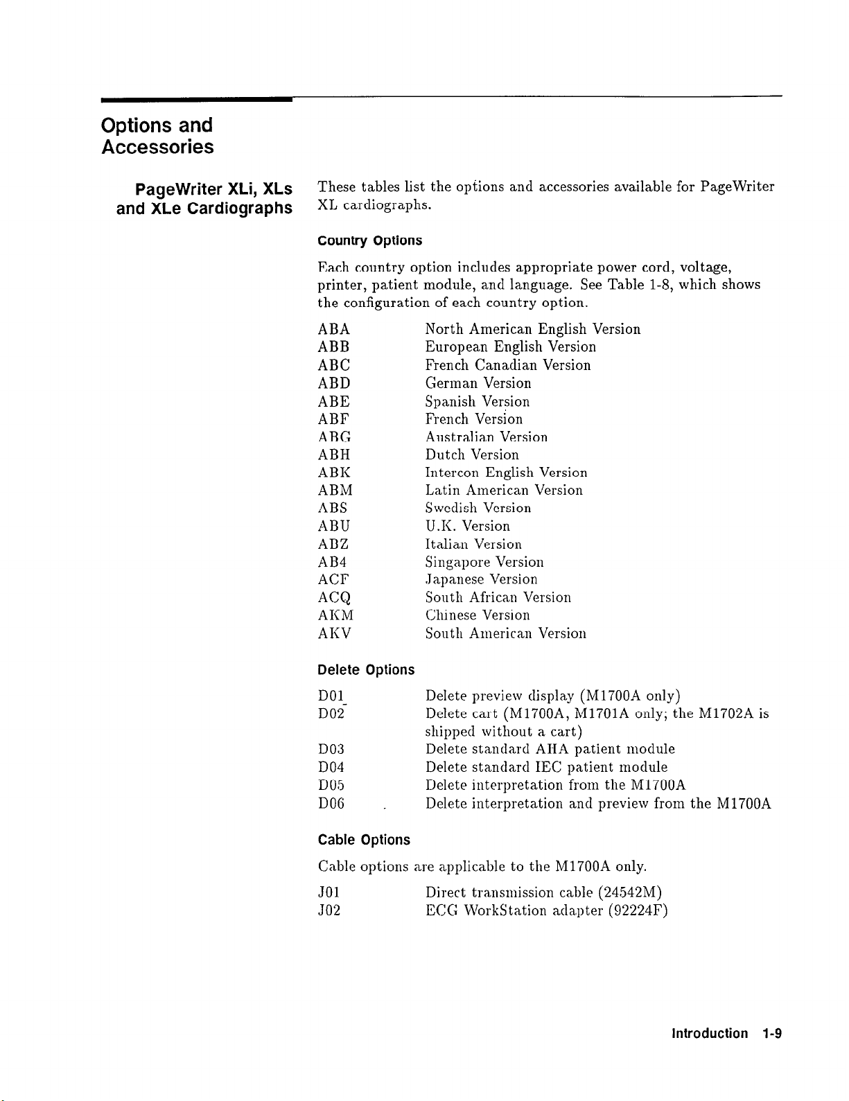
These tables list the options and accessories available for PageWriter
XL cardiographs.
Country Options
Each country option includes appropriate power cord, voltage,
printer, patient module, and language. See Table 1-8, which shows
the configuration of each country option.
ABA
ABB
ABC
ABD
ABE
ABF
ABG
ABH
ABK
ABM
ABS
ABU
ABZ
AB4
ACF
ACQ
AKM
AKV
North American English Version
European English Version
French Canadian Version
German Version
Spanish Version
French Version
Australian Version
Dutch Version
Intercon English Version
Latin American Version
Swedish Version
U .I<. Version
Italian Version
Singapore Version
Japanese Version
South African Version
Chinese Version
South American Version
Delete Options
DOlDO2
DO3
DO4
DO5
DO6 _
Cable Options
Cable options are applicable to the M1700A only.
JO1
JO2
Delete preview display (M1700A only)
Delete cart (M1700A, M1701A only; the M1702A is
shipped without a cart)
Delete standard AHA patient module
Delete standard IEC patient module
Delete interpretation from the M1700A
Delete interpretation and preview from the M1700A
Direct transmission cable (24542M)
ECG Workstation adqter (92224F)
Introduction 1-9
Page 27
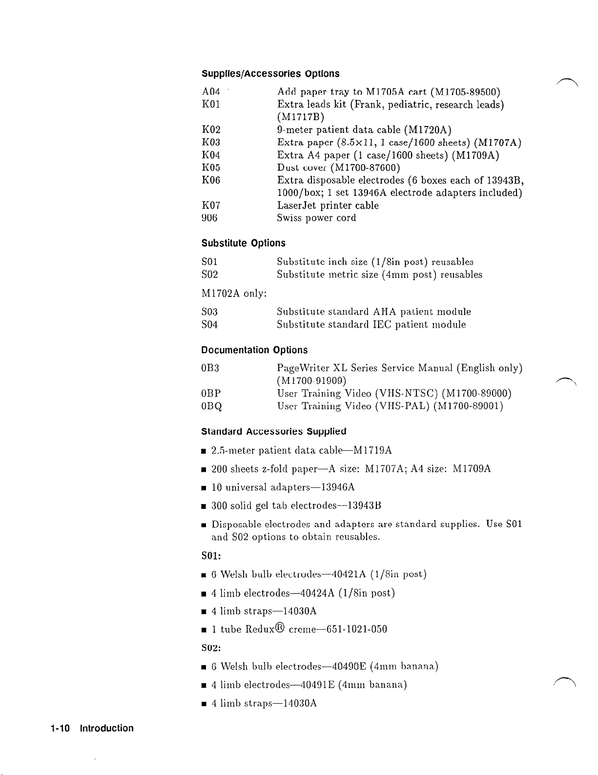
Supplies/Accessories Options
A04
K01
Add paper tray to M1705A cart (M1705-89500)
Extra leads kit (Frank, pediatric, research leads)
(M1717B)
K02
K03
K04
K05
K06
g-meter patient data cable (M1720A)
Extra paper (8.5~11, 1 case/1600 sheets) (M1707A)
Extra A4 paper (1 case/1600 sheets) (M1709A)
Dust cover (M1700-87600)
Extra disposable electrodes (6 boxes each of 13943B,
lOOO/box; 1 set 13946A electrode adapters included)
K07
906
Substitute Options
so1
so2
LaserJet printer cable
Swiss power cord
Substitute inch size (l/sin post) reusables
Substitute metric size (41111~1 post) reusables
M1702A only:
so3
so4
Documentation Options
OB3
Substitute standard ABA patient module
Substitute standard IEC patient module
PageWriter XL Series Service Manual (English only)
(M1700-91909)
OBP
OBQ
User Training Video (VI-IS-NTSC) (M1700-89000)
User Training Video (VI-IS-PAL) (M1700-89001)
Standard Accessories Supplied
H 2.5-meter patient data cable-M1719A
H 200 sheets z-fold paper-A size: M1707A; A4 size: M1709A
n
10 universal adapters-13946A
H 300 solid gel tab electrodes-13943B
H Disposable electrodes and adapters are standard supplies. Use SO1
and SO2 options to obtain reusables.
sol:
m 6 Welsh bulb electrodes-40421A (l/Sin post)
n
4 limb electrodes-40424A (l/gin post)
= 4 limb straps-14030A
H 1 tube Redux@ crerne-651-1021-050
502:
n
G Welsh bulb electrodes--40490E
m 4 limb eleCtJOdeS---40491E (4111111 hI1aI1a)
(4n1111
banana)
H 4 limb straps-14030A
l-10 Introduction
Page 28
H 1 tube Redux@ creme-651-1021-050
/vglue lcm
n
Page Writer XLi
Operating
Guide
(M1700A only)
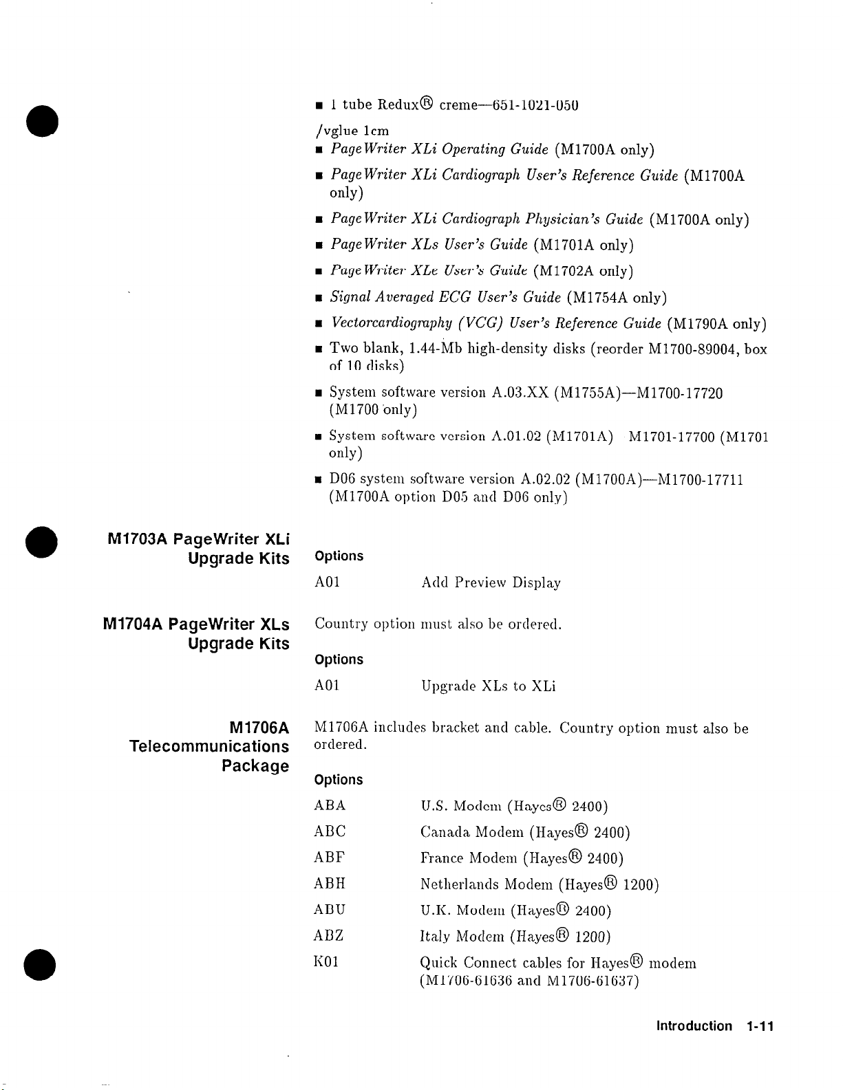
M1703A PageWriter XLi
Upgrade Kits
w Page Writer XLi Cardiograph User’s Reference Guide
(M1700A
only)
H Page Writer XLi Cardiograph Physician’s Guide
n
PageWriter XLs
n
Page Writer XLe User’s Guide
n
Signal Averaged ECG User’s Guide
H Vectorcardiogmphy (VCG) U ser’s Reference Guide
n
Two blank, 1.44-Mb high-density disks (reorder M1700-89004, box
User’s
Guide
(M1701A only)
(M 1702A only)
(M1754A only)
(M1700A only)
(M1790A only)
of 10 disks)
1 System software version A.03.XX (M1755A)-M1700-17720
(Ml700 bnly)
w System software version A.Ol.02 (M1701A)-M1701-17700 (Ml701
only)
m DO6 system software version A.02.02 (M1700A)-M1700-17711
(M1700A option DO5 and DOG only)
Options
A01 Add Preview Display
M1704A PageWriter XLs
Upgrade Kits
M 1706A
Telecommunications
Package
Country option must also be ordered.
Options
A01
Upgrade XLs to XLi
M1706A includes bracket and cable. Country option must also be
ordered.
Options
ABA
1J.S. Modem (Hayes@ 2400)
ABC Canada Modem (Hayes@ 2400)
ABF France Modem (Hayes@ 2400)
ABH
ABU
ADZ
I<01
Netherlands Modem (Hayes8 1200)
U.K. Modem (Hayes@ 2400)
Italy Modem (Hayes@ 1200)
Quick Connect cables for Hayes@ modem
(M1706-61636 and M1706-61637)
Introduction l-l 1
Page 29
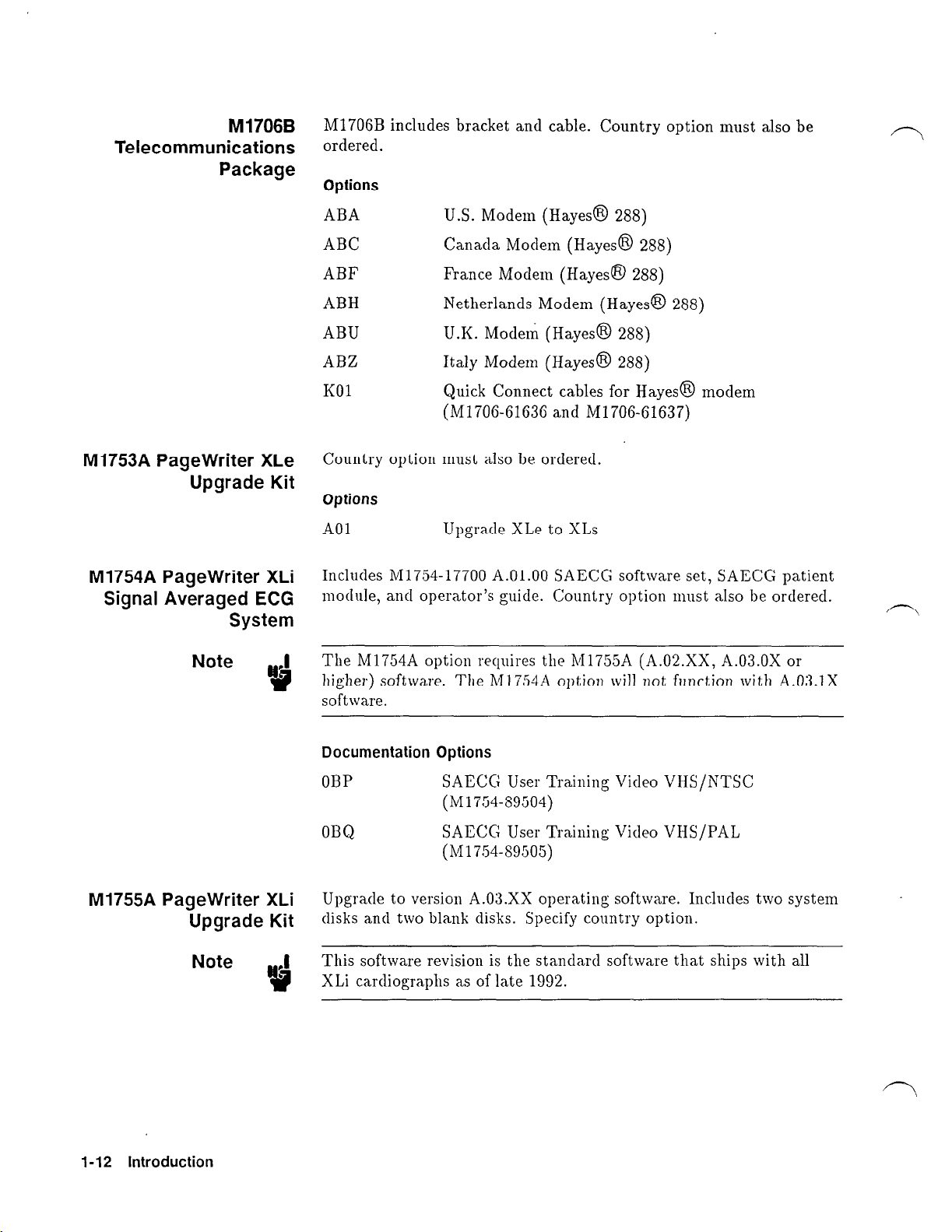
M1706B
Telecommunications
Package
M1706B includes bracket and cable. Country option must also be
ordered.
Options
M1753A PageWriter XLe
Upgrade Kit
M1754A PageWriter XLi
Signal Averaged ECG
System
Note .I
Iv
ABA
ABC Canada Modem (Hayes@ 288)
ABF
ABH
ABU U.K. Modem (Hayes@ 288)
ABZ Italy Modem (Hayes@ 288)
KOl
Country option must also be ordered.
Options
A01
Includes Ml754-17700 A.O1.OO SAECC software set, SAECG patient
module, and operator’s b
The M1754A option requires the M1755A (A.Oa.XX, A.03.OX or
higher) software. The Ml 754A option will not function with A.03.1X
software.
U.S. Modem (Hayes@ 288)
France Modem (Hayes@ 288)
Netherlands Modem (Hayes@ 288)
Quick Connect cables for Hayes@ modem
(M1706-61636 and R/11706-61637)
Upgrade XLe to XLs
Gde. Country option must also be ordered.
M1755A PageWriter XLi
Upgrade Kit
Note .I
t?
1-12 Introduction
Documentation Options
OBP
OBQ
Upgrade to version A.03.XX operating software. Includes two system
disks and two blank disks. Specify country option.
This software revision is the standard software that ships with all
.
XLi cardiographs as of late 1992.
SAECG User Training Video VHS/NTSC
(M1754-S9504)
SAECG User Training Video VHS/PAL
(M1754-S9505)
Page 30
M1756A PageWriter XLi
Direct Digital ECG Fax
Modems
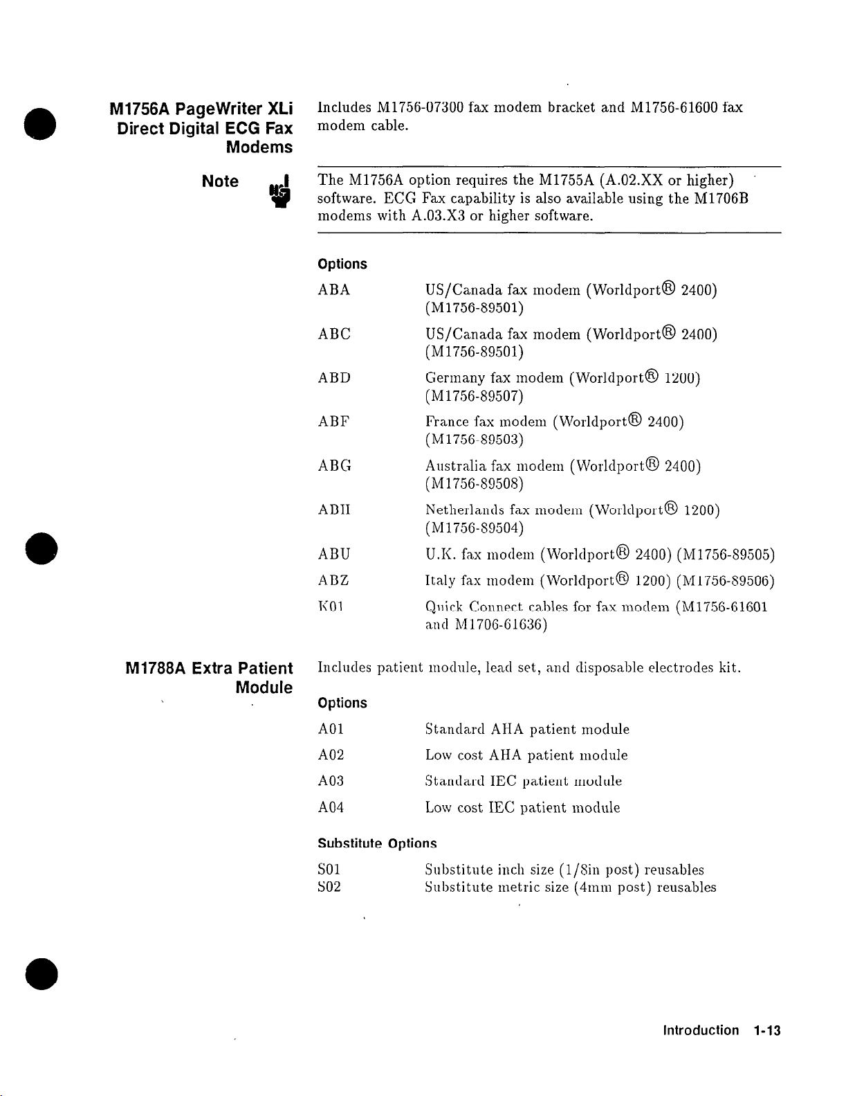
Includes M1756-07300 fax modem bracket and M1756-61600 fax
modem cable.
Note .I
4?
The M1756A option requires the M1755A (A.02.XX or higher)
software. ECG Fax capability is also available using the M1706B
modems with A.03.X3 or higher software.
Options
ABA
US/Canada fax modem (Worldport@ 2400)
(M1756-89501)
ABC
US/Canada fax modem (Worldport@ 2400)
(M1756-89501)
ABD
Germany fax modem (Worldport@ 1200)
(M1756-89507)
ABF
France fax modem (Worldport@ 2400)
(M1756-89503)
ABC
Australia fax modem (Worldport@ 2400)
(M1756-89508)
ABH
Netherlands fax modem (Worldport@ 1200)
(Ml 756-89504)
ABU
ABZ
U.K. fax modem (Worldport@ 2400) (M1756-89505)
Italy fax
modern
(Worldport@ 1200) (M1756-89506)
M1788A Extra Patient
Module
I<01
Quick Connect cables for fax modem (Ml756-61601
and h/11706-61636)
Includes patient module, lead set, and disposable electrodes kit.
Options
A01 Standard AHA patient module
A02 Low cost AHA patient module
A03
Standard IEC patient module
A04 Low cost IEC patient module
Substitute Options
so1
so2 Substitute metric size
Substitute inch size (l/Sin post) reusables
(4nml
post) reusables
Introduction 1-13
Page 31

M1790A PageWriter XLi
Vectorcardiography
Includes M1790-17700 A.O1.OO VCG software set, VCG leadwires,
and manuals. Country option must also be ordered. The part
number for replacement leadwires is M1717B.
Note .I
w
Country Option
Configurations
The M1790A option requires the M1755A (A.03.1X) software version.
The M1790A option will not function with the A.03.OX software.
The following table gives the configuration of each country option.
Table 1-8. Country Option Configurations
Note ,I
I-14 Introduction
t?
In Table 1-S an “A” in the Printer column refers to 8.5 x ll-in
c
paper;
“A4” refers to 210 x 297-mm paper.
Page 32

Installation and Configuration
This chapter describes how to install and configure the PageWriter
XL M1700A, M1701A, and M1702A cardiographs. This information
provides you with a factory-recommended process to use when
assisting customers. The configuration information guides you
through the configuration menu structure, and describes the
configuration choices.
2
Installation
The cardiograph is ready for operation when the followitig tasks have
been properly performed:
n
Patient data cable connected.
H Patient electrodes and leadwires installed on patient module.
H Voltage settin,
n
Battery installed.
n
Software installed (M1701A & M1700A only).
n
Language and line frequency chosen.
n
Paper installed.
n
Clock set (time and date).
n
Configuration parameters chosen.
6 and fuse checked.
H Configuration saved to disk (M1701A & M1700A only).
In
addition to these tasks, the cardiograph should be mounted on the
cart if you are using a cart, and the modem attached to the cart if
you are using a modem.
installation and Configuration 2-1
Page 33

Installing the
Cardiograph and
Modems on the Cart
To install the cardiograph on the cart:
1. Set the cardiograph on the top rails so that the cardiograph’s
rear feet drop into the notches on the horizontal rail edges. The
operator panel must face the cart handle.
2. Slide the cardiograph away from the handle, making sure that the
slots on the feet engage the rail edges.
3. Lock the cardiograph in place by installing the locking screw.
The locking screw passes through the hole in the left cart rail
and screws into the threaded hole on the left underside of the
cardiograph.
Attach the Hayes@ modem to the cart as shown in Figure 2-l:
Note .I
t?
Figure 2-1. Installing the Hayes@ Modem.
Installing the M1756A Fax Modem
ECG fax capability is also available using the M170GB modem with
A.03.X3 or higher software.
To install the fax modem, perform the following steps (see
Figure 2-2):
1. Press the (On-Standby) switch to turn the cardiograph to Standby.
2. Turn the cardiograph AC switch off.
3. Insert the larger connector end of the fax/modem cable
(M1752-61600) into the RS-232C plug on the fax/modem, as
shown
in Figure 2-2.
4. Place the fax/modem flat into the bracket so that its data cable
is retained by the two upright tabs at the narrow end of the
bracket. The battery compartment should be accessible through
the cutout at the wide
end
of the bracket.
2-2 Installation and Configuration
Page 34

Note .I
!I?
A g-volt battery is not essential for fax/modem operation,
5. From the rear of the cart, with the data cable away from you,
pass the modem under the horizontal square bar.
6. Pull the modem towards you, so that the clip on the bracket is
securely over the horizontal bar.
7. Align the hole in the bracket with the tapped hole on the
underside of the bar and secure the modem with the knurled
screw.
8. Bring the fax/modem cables up over the square bar and insert
the smaller end of the faxmodem cable into the plug on the back
of the cardiograph marked Data Corm. Tighten the retaining
screws.
9. Plug the round end of the fax modem cable into the
cardiograph’s modem power connector. Secure the retaining
screws.
10. Insert the telephone cable into either phone connector on the side
of the fax
modem.
A
Figure 2-2. Connecting the Fax Modem Cables.
Installation and Configuration 2-3
Page 35

A. PageWriter XLi Cardiograph
B. Fax Modem Power Cable
C. Fax Modem
D. Phone Line Connector
E. Fax Modem Data Cable
Note .I
w
Printing an ECG on an HP LaserJet Printer
For modem cabling variations see Chapter 8, Parts Lists.
You can print stored ECGs on an HP PCL5 LaserJet printer.
Figure 2-3 shows how to connect the cables between the cardiograph
and the printer.
II II -
--
--
--
/ ;1-,” ’ ,, , ;
D
L.
Figure 2-3. Connecting the Printer Cable.
A. PageWriter XLi Cardiograph
13. LaserJet Printer
C. HP LaserJet Printer Serial Interface Port
D. Serial Data Cable (HP 245426)
rij =-
Ll
.-.. .
p
z?
-
C
92909- 1 I
2-4 Installation and Configuration
Page 36

Setting up the LaserJet Printer
You must set up the LaserJet printer for serial printing before using
it to print stored ECGs from the cardiograph. To configure the
printer for serial printing, perform the following steps.
1. With the printer on, press the ON LINE key until the light is off.
2. Press the MENU key on the printer to step through the settings
until I/O=PARALLEL* appears.
If I/O=SERIAL* appears, the printer is already set for serial
printing.
3. Press the + key until I/O=SERIAL appears.
4. Press the ENTER key on the printer. An asterisk will apear on
the display: I/O=SERIAL*.
5. Press the MENU key and the BAUDRATE setting will appear.
6. Press the + key until BAUDRATE= appears.
7. Press the ENTER key on the printer. An asterisk will appear on
the display: BAUDRATE=19200*.
S. Press the ON LINE key.
The printer is ready to use with your cardiograph.
Installation and Configuration 2-5
Page 37

Configuring the
Cardiograph to Print
EC& on the HP
LaserJet
After connecting the cables, you must configure the cardiograph for
printing on the HP LaserJet.
1. Press (Menu) until the following display appears:
2.
Press Config.
Transmit
hlobal
Store
Config CheckDisk Files
The main configuration menu will appear:
Configuration
ID Transmit Files Exit
3. Press Transmit and the Transmit Configuration menu appears in
the display.
Configuration
Transmit Receive
AutoDial
Exit
4. Press Transmit to configure any of four transmission sites. The
Configure Site menu will appear:
Configure Site
1 2 3 4 Exit
5. Select a site number and the following display appears.
Connection? None
Enter
Choose
Exit
2-6 Installation and Configuration
Page 38

6. Press Choose until you see the choice LaserJet, then press
Enter. The baud rate display will appear.
7. Press Choose until you see the baud rate 19200, then press
Enter.
8. Select whether to print a grid.
If you have unlined paper in the printer, this selection will print
the grid with the ECG.
Your cardiograph is now set up to print to an HP LaserJet when
you select the configured site from the Transmit menu. See the
Page Writer XLi Operating Guide
for information about transmitting
ECGs.
Connecting the Patient
Module
1. Connect the patient data cable to the ECG input jack on the back
of the cardiograph.
2. Connect the other end of the patient data cable to the patient
module as shown in Figure 2-4.
3. Connect the leadwires to the patient module. Match the color
coding on the leadwires to the color coding on the patient module.
(M1702A only: Match the labels on the leadwires to the labels on
the patient module.)
4. Install shorting plugs in the patient module in those positions
without leadwires.
Figure 2-4. Connecting the Patient Module.
A. Leadwires
B. Patient Data Cable
Installation and Configuration 2-7
Page 39

Note .I
If
The M1702A patient module does not feature a signal quality display
or a start button.
Note .I
h?
Changing the Line
Voltage Setting
Caution
e
The M1754A SAECG patient module can acquire both SAECG and
standard ECGs. To get the best results for SAECG, remove the LL
and LA leadwires and install shorting plugs in the LL and LA inputs.
The cardiograph can be set to operate at nominal line voltages of
100, 120, 220, 230, or 240 Volts. It was set at the factory to the line
voltage in your area. Nevertheless, it is a good idea to check the
setting, especially if the cardiograph was brought from an area with a
different line voltage.
The cardiograph can be damaged if plugged into the incorrect voltage
or if fused incorrectly.
The voltage setting appears in the line module window. The line
module is located on the rear panel immediately to the right of
the AC switch (see Figure 2-5). If the voltage setting is incorrect,
change it to the correct setting for your area using the procedure that
follows. If you need to change the voltage setting, be sure to also
check the line fuses.
2-8 Installation and Configuration
A B
M 1700-47
Figure 2-5. The Line Module and AC Switch.
A. Voltage selection drum
B. Fuse holders
Page 40

To change the voltage setting:
1.
Unplug the power cord from the line module.
2. Open the line module door with a small bit screwdriver.
3.
Remove
the voltage selector drum from the line module. The
voltage selections (marked on the selector drum) are 100, 120, 220,
or 240.
Do not rotate the voltage selector drum while it is installed. Doing so
will damage the drum and the line module assembly.
4.
Rotate the drum so that the correct voltage will appear in the
window when the line module door is closed, then reinstall the
drum. Table 2-l shows the correct settings for each nominal line
voltage.
Table 2-1. Line Voltage Settings
Voltage
Setting
220, 230
Nominal Line
Voltage
1220
5. Pull out the fuse holders and check that the line fuses are the
correct rating for the selected voltage (see Table 2-2). If the fuses
are correct, reinstall the fuse holders and proceed to the next
step. If the fuses are incorrect, proceed to the next procedure,
“Changing the Line Fuses.”
6. Close the line module door. Check again that the correct voltage
setting for your area appears in the window.
Table 2-2. Line Fuse Ratings for Voltage Settings
Line Fuse Required
V, 3AG style time delay
V, 5 x 20 mm time delay
100, 120
220, 240
Voltage settings
2.5 A, 250
fuse (HP part number 2110-0015)
1.6 A, 250
fuse (HP part number 2110-0931)
Installation and Configuration 2-9
Page 41

Changing the Line
Fuses
The cardiograph uses two line fuses. Table 2-2 lists the fuse rating
requirements for the line voltages. The correct fuse must be installed
in the cardiograph before you turn it on. Fuse rating requirements
are also printed on the product rating label on the back of the
cardiograph.
1. Unplug the power cord from the line module.
2. Open the line module door with a small bit screwdriver.
3. Pull out the fuse holders and check that the line fuses are the
correct rating for the selected voltage. Refer to Table 2-2. If you
need to install line fuses with a different rating, you will also need
different fuse holders. Fuses for lower voltages require fuse holder
part number 2110-0686; fuses for higher voltages require fuse
holder part number 2110-0687.
4. Place the fuses in the fuse holders and push each fuse holder
back into the line module. Make sure that the arrows on the fuse
holders point in the same direction as the arrows on the line
module door.
5. Close the line module door.
2-10 Installation and Configuration
Page 42

Installing the Battery
This procedure describes installing the battery for the first time.
If you are replacing a battery, refer to the battery replacement
procedure in Chapter 7, “Removal and Replacement.”
Note .I
Warning
Q?
The cardiograph is primarily a battery-powered instrument. It will
not operate without the battery, even if it is plugged into AC power.
Use only HP battery assembly M1721A.
The battery is relatively heavy for its size. Support the battery from
underneath as you install it to prevent it slipping and possibly causing
injury.
To install the battery:
1. Open the cardiograph’s battery compartment by loosening the
two thumbscrews on the back of the cardiograph (as shown in
Figure 2-G), and pulling the battery holder out.
Note
:I
+&
Figure 2-6. Installing the Battery.
A. Battery door
B. Thumbscrews
Figure 2-6 shows the M1700A; other models are similar.
2. Install the battery
on
the battery holder. Make sure the tab on
the door fits into the slot on the battery (refer to Figure 2-7).
Installation and Configuration 2-l 1
Page 43

Figure 2-7. Fitting the Battery Holder Tab Into the Battery Slot.
A. Battery slot
3. Gently slide the battery and holder into the battery compartment
until completely seated.
Note
u
4. Finger-tighten the thumbscrews on the battery holder.
5. Connect the power cord to the cardiograph, then plug the cord
into an AC outlet.
6. Turn
on
the AC switch on the back of the cardiograph. The green
AC indicator on the front panel should light up.
7. Press the (On-Standby) switch to turn on the cardiograph. The
cardiograph will begin its power-on sequence. The M1700A and
M1701A cardiographs will briefly display PageWriter XLi or
PageWriter XLs in the keyboard display, then display the code
6503 (this code indicates that the software is not yet installed
and there is no System disk in the disk drive). At the same time,
all of the control panel indicators will light up, including the
red low-battery indicator and the green charge indicators. The
M1702A cardiograph will display a line of asterisks for about two
minutes as it loads software from its built-in ROM. During this
time, it may prompt for language and line frequency.
S. Press ion-Standby) again to place the cardiograph in Standby. When
the cardiograph is in Standby, it is not operational, but it is
powered.
To ensure full battery capacity, charge the battery for 24 hours
:’
following its installation in the cardiograph.
,r7
,r7
2-12 Installation and Configuration
Page 44

Caution
If the cardiograph will be stored for longer than one month, remove
the battery from the unit.
Installing the Software
on the Ml700 & M1701A
The,software for the Ml700 is provided on two disks and the software
for the M1701A is provided on one disk. The software is loaded into
memory when the disk is in the drive when the cardiograph is turned
on.
To install the software:
1. Press the [On-Standbd switch to place the cardiograph in Standby.
2. Insert the appropriate system disk in the disk drive.
n
If you have no other applications to install, install the A.03.00
system disk (M1700-17920).
n
If you want to install Ml754A SAECG software later, install the
A.03.00 system disk (M1700-17920).
H If you want to install M1790A VCG software later, install the
A.03.10 option disk (M1700-17921).
H If you have an Ml701 PageWriter XLs cardiograph, install the
Ml701 system disk (M1701-17900).
3. Press [On-Standby) to turn the cardiograph On.
n
If no software is installed in the cardiograph, the cardiograph
will begin immediately to load the software from the disk.
n
If software is already installed in the cardiograph, the
prompt Load configuration : followed by the name of the
configuration disk appears on the display.
Note .I
.
t?
Note
:’
u
If you do not want to load the configuration shown, remove the disk
and place the cardiograph in Standby. Find the correct disk and
restart this procedure at step 2.
4. Choose a language and power line frequency when prompted.
If you load the software from a configuration disk, the language and
line frequency prompts will not appear because these selections are
part of the stored configuration. See “Configuration Files,” later in
this chapter.
5. When the software installation is complete, the main menu
appears
on
the display. Remove the disk and store it in a cool,
dry, dust-free location, away from magnetic fields.
G. Check the battery level and AC indicator lights. The AC indicator
and one or more of the green battery level indicators should be
lit. The red “low battery” indicator should be off, though if the
battery is low the green indicators will be off and the red indicator
will be on.
Installation and Configuration 2-13
Page 45

Note .I
$
The battery level indicators function only after software is installed.
To verify battery capacity, turn on the unit while the cardiograph is
connected to AC power and the AC switch is on. The cardiograph
must be connected to AC power when verifying battery capacity.
Once the software is installed, it does not need to be reinstalled
unless the cardiograph loses battery power or has a system failure, or
if you want to load upgraded or custom-configured software.
,rl
Installing the Software
on the M1702A
Loading the Paper
The software for the M1702A is stored in ROM and loaded into
memory automatically when the cardiograph is turned on for the
first time, or after the battery has been replaced. This process takes
about two minutes. During this time, you will be prompted for
language and line frequency.
The cardiograph uses continuous-feed thermal paper, HP part
number M1707A (A size) or M1709A (A4 size). To load the paper:
Release the printer door latch on the left side of the cardiograph
1.
and slide the printer door to the left.
2.
Remove the paper from its packaging but do not remove or
discard the cardboard backing.
Slide the paper stack (cardboard down) into the compartment.
3.
The paper should feed grid-side up over the top panel of the
printer door.
4.
Pull the free end of the paper back to the far end (latch end) of
the top panel (see Figure 2-S).
Slide the printer door back into place making sure that it latches.
5.
Press (Page-) to advance the paper to the beginning of the
6.
next page.
2-14 Installation and Configuration
Page 46

Figure 2-8. Loading the Paper.
A. Paper Door Latch
B. Paper Sensing Hole
C. Paper
D. CardboaLrd Backing
E. (Page) Key
Installation and Configuration 2-15
Page 47

Setting the Date and
Time
The main menu, shown here, allows you to set the date and the time.
Auto 3x4,3R I,II,III
Report Format
Leads
04/01/1990 02:23:34PM
Note .I
w
The date format, date separators, time format, and time separators
are global configuration parameters. Changing the global
configuration is explained later in this chapter.
To set the date, press the softkey directly below the date. The date
change display appears:
Date? 04/01/1990 (MM/DD/YYYY)
Enter Clear Exit
To set the time, press the softkey below the time. The time change
display appears:
Time? 02:23:34 PM (I~H:MM:SS)
Enter AM/PM Clear
Exit
Enter Stores an entry after checking its validity, then
returns you to the main menu.
AN/PM
Appears only for the time change display and only
when the cardiograph is configured for the AM/PM
time format.
Clear
Exit
When the change display appears, the cursor highlights the first
(leftmost) digit of the date or time. To change the date or time,
simply type in the new numbers.
time to 03:45:12 PM, simply type the digits 034512. The system
automatically inserts the separators in the proper places. To change
a single digit, use the left and right arrow keys, (iJ and 0, to move
the cursor over the digit you want to change. Then type the new
digit. When you are satisfied the new date or time is correct, press
Enter or Exit to store it as the cardiograph’s current date or time.
2-16 Installation and Configuration
Clears erroneous entries and returns the currently
stored date or time to the display.
Same as Enter .
Par example, to change the
Page 48

a
Configuration
The cardiograph is designed to provide custom operation. The
configuration parameters allow you to program the cardiograph for
the most useful and efficient operation. Typically the cardiograph is
configured only during initial installation.
Note ,I
Yir
Configuring the M1700A
and M1701A
Note
:’
t?
Software revisions A.02.00 (M1755A) or later allow you to select
either XLi, Preview Plus, or SAECG as the default configuration.
Set the Power on application global parameter to the application you
want the cardiograph to start up in.
This section describes the menu structure that enables you to
configure the cardiograph’s operating parameters. Each menu choice
is described briefly in a list, then in more detail in the narrative
section that follows the list.
Press CMenu) until the following display appears:
Transmit Store Config CheckDisk Files
The Transmit key appears only on the M1700A. Only the M1700A
has transmission capability.
Press the Config softkey to display the main configuration menu:
Configuration
Global
ID Transmit Files
Exit
Note
t?
If this is not the initial configuration, you must type in the
:’
cardiograph’s password (if one has been set) before you can make any
changes to the configuration.
Installation and Configuration 2-17
Page 49

The softkeys function as follows:
Note ,I
Q?
Global
Allows you to set the operating parameters of the
cardiograph. The Global configuration affects all
cardiograph operations.
ID
Allows you to choose which patient identification
entries are requested before recording an ECG.
Transmit
Allows you to set the communication parameters for
transmitting and receiving ECGs. This key appears
only on the M1700A because only the M1700A has
ECG transmission capability.
Files
Allows you to store a configured copy of the
cardiograph software to disk, or to print the
configuration settings.
Exit
Returns you to the previous menu.
When you make extensive changes to the system configuration, it is
recommended that you print the configuration and save it on disk
(the procedure for storing the system configuration is described under
“Configuration Files” later in this chapter). If the software is lost
due to loss of battery power, or if different configurations are used
regularly
is
nluch
on
the same cardiograph, restoring a custom configuration
quicker and easier from disk than by manually entering the
changes.
Configuring the M1702A
Note .I
t?
Press Menu until the following display appears:
Configuration
Exit
Global
Global
ID
Print
Allows you to set the operating parameters of the
cardiograph. The Global configuration affects all
cardiograph operations.
ID
Allows you to choose which patient identification
entries are requested before recording an ECG.
Print
Exit
Prints the cardiograph configuration.
Returns to the main menu.
You cannot save the M1702A configuration. You should print the
M1702’s configuration, so that you can restore it if the battery is
removed, or if changes are made to the configuration.
2-18 Installation and Configuration
Page 50

Selecting Configuration
Parameters
When you select or change configuration parameters, the method is
generally the same whether you are selecting Global, Transmit, or ID
parameters. The display will be similar to:
Initial Interpretation? Reasons
Enter Choose
Exit
In this chapter, this type of display is referred to as the parameter
selection display. The message line on top displays the parameter and
its current setting. The softkey labels are displayed on the bottom
line.
Enter
Choose
Tab
Leads
Previous
Exit
Accepts the current setting, then advances to the
next parameter in the list; or returns to the menu
if pressed when the last parameter in the list is
displayed.
Advances through the list of choices for the specified
parameter.
Appears only for the “Custom” parameters in the
Global list. Used to select the leads for the custom
format. Moves an underscore cursor to the lead to be
changed, then Choose is used to advance through
the list of choices.
Used to select rhythm leads in “Default Auto?”
parameter in global configuration.
Returns to the previous parameter (does not appear
when the first parameter is displayed).
Returns to the menu.
Installation and Configuration 2-19
Page 51

Global Configuration
Pressing Global
(from the configuration menu) brings up the
parameter selection display. The first parameter in the Global
list appears. Table 2-3 lists each Global parameter and its setting
choices. The factory default settings are shown in
There are explanations following the table for those parameters that
cannot be adequately explained in the table’s Comments column.
Table 2-3. Global Configuration Parameters
boldface type.
Parameter
[nitial Interpretation?l
Zopy Interpretation?l
4utoStore?3
Patient ID required?
Setting Choices
Reasons
None
Measure
Interpret
Severity only*
Reasons
Extend Measure
None
Severity only*
Choice
Measure
Interpret
Yes
No
Yes
No
Comments
See “Interpretation Parameters” section
following this table.
See explanations following this table.
Determines whether an Auto ECG is
automatically st,oretl without operator
intervention.
Appears only if AutoStore is “No.”
Determines whet,her t,he cardiograph
will require patient ID information
before recording an Auto ECG. If
AutoStore is “Yes,” this parameter is
“Yes.”
1 This
paramter appears
2 This parameter appears on A.03.XX software only.
3 This parameter does not appear 011 the Ml 702A cardiograph.
only on the Ml 700A cardiograph
2-20 Installation and Configuration
Page 52

Table 2-3. Global Configuration Parameters (continued)
Parameter
Auto Frequency Response?
Manual Frequency Response?
Line Power Filter?
Line Power Frequency?
Filter Key?
Auto print speed?
Default Auto?
Default Manual?
Setting Choices
.15-150 Hz
.05-150 Hz
.5-150 Hz W
Comments
W = Baseline Wander filter. See
Page Writer XLi Physician’s
Guide for
more information.
.15-40 Hz
.5-40 Hz W
.05-100 Hz
.15-100 Hz
.5-100 Hz W
.05-40 Hz
.5-100 Hz W
.05-100 Hz
W = Baseline Wander filter. See
Page Writer XLi Physician’s Guide
more information.
for
.5-150 Hz w
.05-150 Hz
.5-40 Hz W
Off
On
60 Hz
50 Hz
BaselineWander & Artifact
BaselineWander
A software filter that removes power
line (AC) interference.
No default-selected during software
installation.
Determines which filter combinations
are active when (Filter) key is on. .
Artifact
25 nun/set Default Auto ECG print speed; can be
50 mm/xc
3x4
overridden from the front panel.
Default format for Auto ECGs.
3x4,lR I Determines row k column notation for
3x4JR I, II, III ECG. Rhythm strip leads also selected
6x2
here (“R.” means rhythm strip).
3 Default format for Manual ECGs.
6
Selects number of leads on Manual
12 ECG.
Installation and Configuration 2-21
Page 53

Table 2-3. Global Configuration Parameters (continued)
Parameter
Leads?
Custom 3 lead group?
Custom Manual 6?
Units of Measure?
Print Interpretation?l
rime format?
rime separator?
Setting Choices
AHA
IEC
I aVF V2
II aVF Vl V2 V4 VG
English (lbs/ins)
Metric (kg/cm)
Reasons
Extend Measure
None
Severity only*
Choice
Measure
Interpret
AM/PM
24 Hr
HH:MM:SS
HH.MM.SS
Comments
Selects between two lead standards.
Affects lead labels on report.
You can set any combination of the
available leads for routine usage. See
explanations following this table.
You can set any combination of the
available leads for routine usage. See
explanations following this table.
Used for height and weight entry.
Determines Patient ID units on the
ECG.
See “Interpretation Parameters” section
following this table.
gate format?
MM/DD/YYYY
DD/R4M/YYYY
YYYY/MhI/DD
Date
separator?
MM/DD/YTYY
MM.DD.YYYY
MM-DD-WYY
MM DD YYYY
Decimal format?
xxx,xxx.xx
xxx.xxx,xx
paper size?
A (8.5 x 11 in)
A4 (210 x 297 mm)
4uto Print?
Yes
No
$utoCopy?
No
Yes
1 This paramter appears only on the M1700A cardiograpl~
2 This parameter appears cm A.03.XX software only.
Selects between “A” (8.5x 11 in) and
metric “A4” (210x297 mm).
Allows or suppresses printing of Auto
ECGs (A.02.XX and higher software
only).
See explanation following this table.
2-22 Installation and Configuration
Page 54

Table 2-3. Global Configuration Parameters (continued)
Parameter
Copies? (l-5)
Location code?
Cart ID?
Institution Name?
Confirmation1
Setting Choices
Type number between 1 and 5.
Type a 5-character code.
Type a 4-character code.
Type name (up to 40 characters).
PRELIMINARY -
MD MUST REVIEW.
Type a label up to 30 characters.
User A label?
User B label?
Battery timeout?
Type a label, up to 8 characters.
Type a label, up to 8 characters.
Type minutes between
3 and 999.
Set keyboard?
lower
UPPER
Special applications?
No
Yes
Research leads?*
No
Yes
Default Adult Criteria?‘,*
08
P4
Default Pediatric Criteria?r,* P4
08
ID criteria version entry?2,3
No
Yes
Comments
If AutoCopy is “Yes,” selects number of
automatic copies after original
recording.
See explanations following this table.
See explanations following this table.
See explanations following this table.
See explanations following this table.
See explanations following this table.
See explanations following this table.
Allows configuration of research leads,
ECG storage mode, and lead system.
See
the
Page Writer XLi Physician’s
Guide
for more information.
Allows 4 additional unipolar leads of
user’s choice.
OS is the adult analysis criteria; P4 is
the pediatric analysis criteria.
Yes causes “Criteria Version?” prompt
to appear during patient ID entry.
Allows use of criteria residing on ECG
hlanagement System.
Default ID criteria version?3
ECG storage mode?2,3
User-defined - 2 characters.
Standard (250 samples/set)
Special (500 samples/set)
Lead system?*
Standard
Cabrera
Power-on application?
XLi
Prev+
SAECG
Password?
1 This parameter appears only on the Ml700A cardiograpl~.
2 This parameter appears only if “Special Applications” is set to “yes.”
3 This parameter does not appear on the Ml702A cartliograplr.
User-defined (up to 8 characters).
Appears only if “ID criteria version
entry?” is yes.
Special allows ECGs to be measured
and interpreted on an M1700A.
If available.
Allows your cardiograph to start up in
the selected application (appears with
A.02.XX and higher software only).
Installation and Configuration 2-23
Page 55

Interpretation Parameters
These parameters determine the amount of information included in
an Auto ECG report.
w InitialtInterpretation controls the information that appears on the
ECG when it is first taken.
n
Copy Interpretation controls the information that appears on
subsequent copies of the ECG.
n
Print Interpretation controls the information that appears on a
printout of a stored ECG.
Each setting choice adds another piece of information to the printed
ECG. The settings’ definitions are:
None Prints waveform and patient ID.
Severity only
Measure
Interpret
(A.OS.XX only) P ’ t
rm s waveform, ID, and severity.
Prints waveform, ID, and measurements summary.
Prints waveform, ID, measurements summary, and
computer-generated interpretation.
Reasons Prints waveform, ID, measurements summary,
computer-generated interpretation, and interpretive
reason statements.
Extend
Measure
Choice
Prints a tabular summary of all measurements
performed on ECG data. An alternative report.
Allows you to select the level of information included
when an ECG is copied or printed from disk
without having to change the overall instrument
configuration.
Power-on Application (M1755A A.02.XX and Higher Software Only)
To select which application (XLi, Preview Plus, or SAECG) the
PageWriter will start up with, set the “Power
on
application”
parameter to that application.
Line Frequency
This parameter selects the frequency of the filter enabled by the
line power filter. The user usually selects the frequency in response
to a prompt from the system during initial insta.llation. However,
the system will not prompt for a frequency selection when a
custom configuration is loaded. Including this parameter in Global
configuration allows the user to change the frequency selection after
initial software installation.
2-24 Installation and Configuration
Page 56

Custom Lead Groups
Besides the pre-defined lead groups, you can configure one group
of three leads and one group of six leads that may be selected for
Auto 3~4,3R, Manual 3 or Manual 6 reports. These lead groups will
appear and be recorded when you select Custom 3-lead group and
Manual 6-lead reports from the main display.
1. Configure custom lead groups from global configuration when the
display as shown below appears.
Custom 3 lead group I aVF V2
Enter
Choose Tab Previous Exit
2. Press Choose to change the lead from I.
3. Use Tab to move to the next lead field. In this case, the next lead
field is aVF.
4. Press Choose in each field to change the lead setting.
5. Press Enter to save the selections.
AutoCopy
When AutoCopy is set to Yes, the cardiograph automatically prints
one or more copies (depending on
“Copies” parameter setting) of the
Auto ECC after the original is recorded. When AutoCopy is set to
No, you must press (copy) to receive an additional printed copy.
Installation and Configuration 2-25
Page 57

ECG Management Parameters
These parameters trigger processing protocols on the ECG
management system, and provide information for ECG tracking.
These parameters include:
Location code
A user-defined numeric code limited to five digits.
The first three digits represent the institution and
the last two characters represent the department. It
can be used to identify the origin of the ECG, such
as ER, ICU, CCU, or the department number.
Cart ID
A user-defined code limited to four digits. Identifies
the cardiograph to the ECG management system.
Institution
Name
Confirmation
Identifies the institution, such as “Sharon General
Hospital.” Limited to 40 characters.
A label that appears on ECGs. Can be the
default label (see table) or user-defined, such as
“MD signature X
>>
Limited to 30 characters. Available only on the
MlTOOA.
User A label
User B label
Enter user-defined label such as “Smoker?” or
“Apnea.
7” that appears in ID entry process. Limited
to eight characters.
Battery Timeout
To lengthen battery life, the cardiograph turns off after the period of
time specified by this parameter. The time is measured in minutes
from the completion of the last operation, the last key press, or
disconnection of patient leads. The time-out function is disabled
when the cardiograph is plugged into AC and the AC switch is on.
Password
To protect your configuration settings from casual changes, you can
require password entry to access the configuration. This password is
set in Global configuration.
Caution
IP
2-26 Installation and Configuration
If the password is set and forgotten, you will be unable to change the
cardiograph configuration without reinstalling the factory software.
Page 58

ID Configuration
When you press ID from the configuration menu a parameter
selection display appears. The following list presents each ID
configuration option. You choose either Yes to include or No to
exclude that item from the patient ID information prompted for
while entering patient ID. Yes is the default choice for all except the
last three items.
n
Allow NAME entry?
n
Allow AGE entry?
w Allow SEX entry?
n
Allow HEIGHT entry?
n
Allow WEIGHT entry?
w Allow BP entry?
n
Allow RACE entry?
n
Allow DX entry?
w Allow RX entry?
n
Allow OPERATOR entry?
n
Allow DEPARTMENT entry?
n
Allow ROOM entry?
w Allow REQUESTED BY entry?
n
Allow USER A entry? (“USER. A” is replaced by the label defined
in global configuration.)
n
Allow USER B entry? (“USER B” is replaced by the label defined
in global configuration.)
w Allow STAT ECG entry? (Instructs ECG Management System to
process this ECG first. M1700A only.)
Installation and Configuration 2-27
Page 59

Transmit Configuration
When you press Transmit-, the “Configure” menu for transmit
appears in the display.
Note .I
ti?
The transmit information in this section applies only to the M1700A
cardiograph.
Configure
Transmit Receive AutoDial Exit
The following list briefly describes the function of each menu
selection. A detailed discussion of each selection follows the list.
Transmit Use this key to configure the cardiograph for four
transmission sites.
Receive
Use this key to select the receive connection type and
its baud rate.
AutoDial
Use this key to select a site to which the cardiograph
automatically sends an ECG when you transmit.
Exit
Transmit
Returns you to the previous menu.
The Transmit key brings the Configure Site menu to the display:
Configure Site
1
2
3 4 Exit
When you select a site number, a parameter selection display
appears.
The default setting for each parameter is shown
Table 2-4 lists each parameter and the settings available.
in
boldface type.
2-28 Installation and Configuration
Page 60

.
Table 2-4. Site Transmission Configuration
Parameter
Connection?
Baud Rate?
Phone number?’
Dial Type?’
Pause Length? Seconds1
Print grid on report?*
Settimz Choices
None
Direct
Programmable Modem
Hardware Modem
Fax programmable modem
LaserJet
9600
19200
300
1200
2400
(Blank field)
Tone
Pulse
2, 4, 6, 8, 10 (sets)
Yes
No
Comments
Hard wire connection to receiver.
The Hayes@ M1706A modem.
Not supported.
A.02.XX and higher software using M1756A
modem.
A.03.X3 and higher software using M1706B
modem.
A.OJ.XX software.
Defaults: 9600 for Direct, 2400 for
Programmable Modem and Fax
Programmable Modem, 1200 for Hardware
Modem, and 19200 for LaserJet. This
parameter does not appear if you select None
as the connection tvne.
Type phone number, 36 characters max. See
explanation following this table.
Tone is for audio tone dialing, pulse is for
rotary dial system.
See explanation following this table.
A.03.XX software only
1’This parameter appears only when the Progranu~whle Modem is selected as the connection type.
2 This parameter appears only when Fax Programmable MO&XI or LaserJet is selected as connectin type.
Entering the Phone Number. When you advance to the phone number
parameter,
followed by an underscore cursor.
the Phone number? prompt appears on the display
Two additional softkey labels,
Pause(,) and Tone(W) , also appear. To enter the phone number,
type the numerals on the keyboard. The number will appear on
the display at the
“Phone number?”
prompt. The phone number is
limited to 36 characters, including tone and pause characters.
The Paused , > softkey inserts pauses (which appear as commas in
the display) into the dialing sequence. The pause avoids dialing
errors that can occur if the number is sent too rapidly. An example
would be 1,234,567,8900. The length of the pause is selected with the
pause length parameter.
The Tone(W) softkey inserts a tone wait (which appears as a W in
the display) into the dialing sequence. The W in the number instructs
the modem to wait for a dial tone before completing the dialing
sequence.
For example, 9W1,234,567,8900 instructs the modem to
dial the 9 (for an outside line), then wait for a dial tone before it
dials the rest of the number.
If you want to change one of the characters, use the left and right
arrow keys, (iJ and 0, to move the cursor to the digit you want to
Installation and Configuration 2-29
Page 61

change, and type the new number. The new character will replace
the old one.
character you want to change, then retype the erased part, with any
changes you want to make.
Receive
Or you
can use the backspace key to erase back to the
Parameter
Connection?
Baud Rate? 91300
Setting Choices
None
Direct
Programmable Modem
Hardware Modem
Fax/programmable modem
19200
300
1200
2400
When you select Receive,
The following table lists each parameter and the settings available.
The default setting for each parameter is shown in boldface type.
Table 2-5. Site Receive Configuration
8
AutoDial
the parameter selection display appears.
Comments
Hard wire connection to receiver.
The Hayes@ M17OGA/B modem.
Not supported.
A.02.XX and higher software using M1756A
modem.
A.03.X3 and higher software using M170GB
modem.
Defaults: 9600 for Direct, 2400 for
Programmable Modem and Fax/programmable
modem, 1200 for Hardware Modem. This
parameter does not, appear if you select “None”
as the connect,ion type.
When you select AutoDial from the “Configure” menu, the
AutoDial site? prompt appears in the display. Use the Choose
softkey to select the site (1, 2, 3, 4, or None) that the cardiograph
will automatically dial when the operator issues a transmit
command.
2-30 Installation and Configuration
Page 62

LaserJet Printer
Configuration (A.OS.XX
Software Only)
The following table lists the settings to choose to configure the
cardiograph to print on a LaserJet printer.
Note .I
h?
Configuration Files
Only ECGs (not SAECGs, VCGs, Store log reports, or configuration
reports) can be printed on a LaserJet printer. Only PCL5 LaserJet
printers are able to print from a cardiograph.
Table 2-6. LaserJet Printer Configuration
When you press Files (from the main Configuration menu) the
following menu appears on the display:
Configuration file jobs
Print Exit
Store
Print
Store
Stores the configured software on disk.
Prints a copy of the cardiograph configuration.
Note ,I
.
I?
Note ,I
.
t?
Exit
Store the configured software each time it is changed. Print a copy of
the cardiograph configuration and keep it with the configuration disk.
If the software is lost due to loss of battery power, you will be able to
easily restore the cardiograph to its latest configuration.
The M1702A can only print its configuration.
Store
Storing the configured software creates a disk that contains the
software, language option, and (on the M1700A only) criteria
version as well as the configuration. The disk can then be loaded at
power-on to initialize the cardiograph with a known configuration.
When you press Store, the prompt “Enter disk label?” appears
followed by a blank field. This label, which is optional, can be up
to 16 characters long, and is displayed during installation of the
software. Examples of labels are “11/90 Config.” or “Dr. Jones
Disk.”
Returns you to the main configuration menu.
Installation and Configuration 2-31
Page 63

After you type in the name and press IEnter), the prompt “Insert
disk, then press Continue.” appears. When you do so, the
cardiograph displays “Storing cardiograph configuration . . . ”
until the storage is complete. Then “Disk (your label) created.”
is displayed. Press Exit to get back to the main configuration menu.
Note .I
w
Note .I
‘Jo
With the A.02.XX and higher software and SAECG application
installed and configured, both software configurations can be stored
on a single flexible disk. This disk can then be used to re-install the
A.02.XX or A.OS.XX software and SAECG application together.
With the A.OS.XX software and VCG application installed and
configured, both software configurations can be stored on a single
flexible disk. This disk can then be used to re-install the A.03.XX
software and VCG application together.
When you press Print the cardiograph prints a copy of its
configuration settings. The message Printing cardiograph
configuration . . .
complete; then you return to the “Configuration file jobs” menu.
appears on the display until the printout is
2-32 Installation and Configuration
Page 64

Operation
3
This chapter briefly summarizes the cardiograph’s operation. This
information is intended for the service person and is not a substitute
for the information in the operator’s manuals. Refer to one of these
manuals for more comprehensive and detailed operating instructions.
n
Page Writer XLi Operating Guide
n
Page Writer XLi Cardiograph User’s Reference
H Page Writer XLi Cardiograph Physician’s Guide
H Page Writer XLs User’s Guide
n
Page Writer XLe User’s Guide
Note
t?
Refer to the appendixes for information on using the SAECG
:I
application, the fax modem, and the VCG application. Refer to the
end of this chapter for information on using Preview Plus.
Operation 3-1
Page 65

The Keyboard and Front Panel
Figure 3-1 shows the keyboard and front panel. Controls and
indicators shown are described on the following page.
47
mrd*r
.5 10 25 50
00.0
0
B
I
ECC Sk‘ Y L&i*
rnmh” ECG sir.
5 10 20 Full “4,
oao 0 0 0
000
C D
I
FiIlW
Figure 3-1. The Keyboard and Front Panel.
E
. . . . .a ..* : . . - . ...*
& &“r;;-L; (--k-J (f%y~ (Le.“] 1
F
. . . ..:‘?.* ..*. . . .
G
000000000001(
00000000000
0000000000~
El0,0000000(7n( 4 -1
lI$EI c @pm@
I
cl
..* -- *: ..*
*.:&..*-
R
S
3-2 Operation
Page 66

A
B
C
D
E
F
G
H
I
J
K
L
M
N
0
P
Q
R
s
l--j
pa-m
llD1
sof tkeys
Icopy)
Low Battery
Battery Level
AC%
Changes the paper speed. It switches between 5, 10, 25, and 50
mm/set for Manual ECGs, and between 25 and 50 mm/set for
Auto ECGs.
Changes the limb and chest lead sensitivity between 5, 10, and 20
mm/mV.
Changes the chest lead sensitivity between full and half size with
respect to the value set by the C-1 key.
Turns artifact and baseline wander filters on and off depending on
which filter or filters are set in configuration.
Allows patient identification entry, review, and edit.
These five keys (fl - f5), called “softkeys,” appear directly beneath
the display window and perform different functions at different
times. When a particular f key is active, a label describing its
function appears above it in the display window.
Changes the softkey selection between two displays.
Starts an Auto ECG recording.
Starts a Manual ECG recording.
Halts any cardiograph function.
Prints a copy of an ECG which has just been acquired.
Advances the paper to the beginning of the next page.
Switches the cardiograph between On and Standby. The
cardiograph is not operational when in standby, but it is powered.
Light indicates that the cardiograph must be plugged in and
recharged.
Lights indicate the remaining capacity level of the battery. When
the battery is frilly charged, all the lights are on. Always check the
battery lcvcl lights before disconnecting AC power.
Light will be on when the power cord is plugged into a wall outlet
and the AC switch is on. This indicates that the battery is
charging. The AC swit,ch is on the back of the cardiograph.
Pressed with (YJ at power on for cardiograph self-test.
The left and right arrows move the cursor when typing information
in data entry fields on the keyboard display. The down and up
arrows select leads on Preview Screen.
The Enter key.
Other Operating
Controls
Note
:’
Yl?
There are other operating controls that are not part of the keyboard.
The knobs that control preview screen contrast and brightness are on
the preview screen front panel (M1700A only). The remote start
button, 0, is located on the patient module (M1700A & M1701A
only). The contrast controls for the keyboard display (above the
keyboard) and the patient module display are key combinations
entered at the keyboard.
The M1702A patient module does not have a display or a remote
start button.
To increase contrast
decrease contrast, press the IShift) and 1;7. To increase contrast on
the patient module display, press (XJ aud a; to decrease contrast,
press (Alt) and 1;;1. You may need to press the a.rrow keys multiple
times to acliicve the contra.st desired.
on
the keyboard display, press IShift) and (iJ; to
Operation 3-3
Page 67

Choosing a Report Format
You can record two types of ECGs:
n
Auto ECGs are l-page, 12-lead ECGs with or without rhythm
strips.
n
Manual ECGsare continuous tracings of 3, 6, or 12 leads.
In addition, if you have the M1754A SAECG option you can record
signal-averaged ECGs. Examples of a few of the ECG types are
shown in the figures on the following pages.
To choose a report format, use the softkeys shown in the menu
display below. This menu also allows you to set the date and the
time (the procedure for setting date and time is described in Chapter
2). If you do not have this or a similar menu in the display, press
a or 1Stop) until you do.
Note ,I
c
t?
Note .I
c
u
The information displayed in the message line (upper line of the
display) depends on the format last chosen. For this reason, your
display may be different than the example shown here.
Auto 3X4,3R I,II,III
Report Format Leads
Report
Format
The Auto Formats are in “row by column” format. “R” means
rhythm strips.
Selects between the Auto or Manual report menus.
Selects the number of leads and the report
presentation.
Auto Formats 1 Manual Formats
3x4,3R
I
04/01/1990 02:23:34PM
The
selections are:
c
I
3-4 Operation
Page 68

Leads
For an Auto report (3x4, 3R and 3x4, 1R only), this
key selects the set of leads used for rhythm strips.
For a single rhythm strip (1R) you select any one
of the twelve leads; the default lead is I. For three
rhythm strips (3R), the lead sets available are:
w I, II, III
H aVR, aVL, aVF
w Vl, v2, v3
n
V4, V5, V6
n
Custom (Default = I,aVF,V2)
For a 3- or 6-lead Manual report, this key selects the
set of leads used (12-lead reports automatically use
all 12 leads). The selections for the S-lead set are the
same as for the 3R sets listed above. The selections
for 6-lead sets are:
w I, II, III, aVR, aVL, aVF
n
Vl, V2, V3, V4, V5, V6
w Custom (Default = II,aVF,Vl,V2,V4,VG)
Note
t?
You can change power-on default leads in Global Configuration.
:’
The lead selections listed above are for the Standard configuration. If
the cardiograph is configured for Cabrera leads, the lead selections
that appear will be different. Also, if pediatric, Frank, or research
leads are connected in place of standard leads, the cardiograph
detects their presence and alters the displayed lead sets accordingly.
Operation 3-5
Page 69

PRELIMINARY-MD MUST REVlEU
I .“R “I
.“L “1
I
-1&/J
LOC 123‘5-0001 Speed IS mm,src L,rnlJ 10 mm/m”
v - V
V
Chc*l:5 mm/m”
Figure 3-2. An Auto 3x4 ECG (3x4).
v,
k 0 ,5-,5O%HI Y
I
I
00013
3-6 Operation
Page 70

Regucltrd b,:
D,. Kc.,,‘,
*RELIMINARY-m MUST REVlEY
I
IVR
“I
I
.“L
“2 “5
j v- v
III
aw “1
LkJ-IL.-j/ 11
LOC 12115-0001
speed 25 mm,src
Figure 3-3. An Auto 3x4 ECG With Three Rhythm Strips (3x4, 3R).
L,lnb IO rdo,mv Chrrl J mm/m”
vf---Jy$:
“6
I
b 0 ,5-l5O%,,Z w
llPlO8
0001.5
Operation 3-7
Page 71

“I
ri
“1
sl’
“I
1m 11115-0001
I
f”
v-” v-
V” -1
Figure 3-4. A Manual 6-Lead ECG.
i’ P id -I-” T T- -P---r-
I2315
I
3-8 Operation
Page 72

Number Of beat*
F,r,rl no,*c
H,lb p,rr ,rrqucncl,
Sampling Irrg”elc~............300 0 HZ
............
...........
....
.?94
..0.30 0 “V
40 HZ
:rp-Y
x
256
“V
1
360
300
Y z “CC,DI
116.00 I,?P..50
37.14 51.71 70.75
ll.1,
31.50 15.50 11.00
-I-+
“V
130 00
9.79 16.09
-1.94J
1 ::~---v-.y
0 IO0 7.00
“alllllrad Icads
Sra,r. 12l”Vlrnrn
300
0
I
IO 170
156
I
I
0 - ,m,
*se -
0
d.,
I : I : I : I
mr 0
i&J
40
4s
,OO 200 300
F,I,crrd lcrdr Vector mr~n’lvdr
Scale. (l”“,rnrn se.,r. 3”Vlrnrn
I
164
1’77
Figure 3-5. An SAECG Report.
X
Y
z
240
100
I20
60
*
0
ms
0 48
JI
178 300 mr
1
Operation 3-9
Page 73

Main Functions
This section discusses the cardiograph features and functions that
you access from the alternate main menu selected by the m key.
To begin, press (Menu) until the following display appears:
Note .I
w?
Transmit Store Conf
I
Transmit Selects stored ECGs for transmission to another site.
Store
Conf ig
CheckDisk
Files
These functions are described in the following pages.
The Transmit softkey appears only on the M1700A.
The M1702A Ihnenu) key brings up the following menu:
Global
Stores the last recorded Auto ECG on disk.
Provides access to the cardiograph’s operating
parameters. Refer to Chapter 2.
Checks the disk and reports how much storage
capacity is in use.
Provides access to the stored files for ID editing,
printing, analyzing (M1700A only), or deleting.
Conf
@ration
ID
CheckDisk Files
ig
Print
Exit
3-10 Operation
Global
ID
Print
Exit
Allows you to set the operating parameters of the
cardiograph. The Global configuration affects all
cardiograph operations.
Allows you to choose which patient identification
entries are requested before recording an ECG.
Prints the cardiograph configuration.
Returns to the main menu.
Page 74

Transmit (M1700A Only)
When you press Transmit the following menu is displayed:
Transmit
Selected
All
NewCroup
Query
Exit
Selected
All
NewGroup
Presents the selection display (the selection display is
described at the end of this section). Allows you to
select one or more stored ECGs for transmission. If
AutoDial is enabled, the cardiograph automatically
dials and transmits the selected ECG(s) to the
chosen site when you press Transmit in the selection
display.
Transmits all the stored ECGs. If AutoDial is
enabled, the cardiograph dials and transmits
immediately. If AutoDial is not enabled, the
following display appears:
Choose Site
1
2
3 4 Manual
Selecting one of the numbers initiates transmitting
to the site assigned to that number. If you
select Manual, the display prompts you to enter
configuration information. Refer to Chapter 2 for
details about configuring autoclial sites.
Transnlits only those ECGs that have not previously
been transmitted.
Note ,I
b
Query
Calls a site to receive ECG information. Query
is used only with an ECG management system.
The PageWriter can receive ECGs from an ECG
rnanagernent systenl on request by using the Query
function. PageWriters with A.Ol.XX software can
only receive text information this way, and cannot
receive ECG traces.
The PageWriter provides two types of Query: standard and
interactive (interactive query is only available with A.02.XX and
higher software).
In standard query text reports (analysis only) are queued at the
system for output to the cardiograph. Only diagnostic and extended
measurement reports can be sent in standard query.
In interactive query, the cardiograph user selects the ECG to receive.
A single patient’s ECG (report and waveform) can be retrieved from
the system this way by answering yes to the question Select an
on-line report.
Operation 3-11
Page 75

Note 1
Yb
Revision A.02.XX and higher software enables the M1700A to
transmit Auto 6x2 ECGs to the F.A.A. ECG management system.
Exit Returns you to the previous menu.
f-7
Store
(M1700A & M1701A only)
Note .I
w
This key stores the current Auto ECG on the disk (Manual ECGs
cannot be stored). An ECG must have a patient ID number before it
can be stored. If the ECG to be stored has no patient ID when you
attempt to store it, the cardiograph asks if you want to give it one. If
your answer is “No,” the cardiograph aborts the store attempt and
returns you to the alternate main menu. If your answer is “Yes,” the
cardiograph takes you through the patient ID entry process as if you
pressed the (ID] key on the front panel.
Once you enter a patient ID and exit the patient ID entry process,
the cardiograph stores the ECG on the disk. The message Storing
ECG appears while the ECG is being stored. Then the display returns
to the main menu.
If the disk you inserted in the drive is new and unformatted, the
cardiograph will ask if you want the disk formatted. Press Yes if you
‘do (formatting takes about 90 seconds), or insert a formatted disk in
the drive at this time. A disk must be formatted for storage to take
place.
The A.02.XX and higher software allows you to erase (reformat)
flexible disks by using CheckDisk (see below).
Config
CheckDisk
(M1700A & M1701A only)
This function allows you to configure the PageWriter. See Chapter 2
for details.
A-01-Xx software
With the A.Ol.XX software, CheckDisk allows you to determine
how much storage capacity remains on the disk. When you press
CheckDisk, a message similar to the following appears in the
display:
Disk 25% full
A.OP.XX and Higher Software
The A.02.XX and higher software enables CheckDisk to reformat
flexible disks as well as determine how much storage space is
available on the disk.
3-12 Operation
Page 76

When you press CheckDisk, the message Reading the disk . . .
appears, followed by a second message that shows the percentage of
storage space available on the flexible disk. For example, you may see
a message such as:
Disk 25% full.
Erase
Exit
If you want to reformat the disk, press Erase.
Files
(M1700A & M1701A only)
This key gives you access to several functions that allow you to
manipulate the stored ECGs in a variety of ways. When you press
this key, this menu appears:
Delete
Log
Edit
Print Analyze
Delete Allows you to delete stored ECGs and SAECGs.
This key brings up the selection display (the selection
display is described at the end of this section). After
you select the patient ID numbers for the ECGs that
you want to delete, press the Delete softkey in
the selection display. The cardiograph displays the
question Start Deleting 1 ECG(s)? (The number
“1” will vary in all messages depending on how
many ECGs were selected.) Press Yes if you want
to continue. The message Deleting 1 of 1 ECG(s)
appears and the ECG is removed from the disk. The
following display appears to confirm that the ECG is
deleted. Press Exit to continue.
Log
1 ECG(s) deleted
Exit
Prints the ECG-Log or Store-Log. The cardiograph
prompts you to select before printing.
The ECG-Log is a list of the last GO Auto and
Manual ECGs recorded on the cardiograph. It shows
the time and date the ECGs were recorded and if
they were stored. The Store-Log lists all Auto ECGs
stored on the flexible disk currently in the disk drive.
It shows if ECGs on the disk were transmitted,
analyzed, or edited.
Operation 3-13
Page 77

Edit
Enables you to edit the patient ID information on
stored ECGs when you press the Edit key on the
selection display. The cardiograph displays the
patient ID information for editing just as it does
when you press the (ID] key on the front panel.
When you finish editing, the cardiograph offers
to store the ECG on the disk. When the storage
is complete or if you press No, the alternate main
menu returns to the display.
Note .I
IQ
On the M1700A only: when you finish editing, the cardiograph offers
to analyze the ECG again. When this analysis is complete (or if you
decline analysis),
then
the cardiograph offers to store the ECG.
Print Prints the selected ECG(s) when you press Print
on the selection display menu (the selection display
menu is described at the end of this section). While
the ECG is printing this message is displayed:
Printing 1 of 1 ECG(s).
When the printout is done, this message is displayed:
Printed 1 ECG(s).
Analyze
This fuuction is available only on the Mli’OOA.
Analyzes the selected ECGs when you press
Analyze on the selection display menu. Also
provides the option of printing the analyzed ECG(s).
While the cardiograph analyzes the ECG(s), these
messages appear:
Reading 1 of 1 ECG(s).
Analyzing 1 of 1 ECG(s).
Storing 1 of 1 ECG(s).
3-14 Operation
When complete, the cardiograph displays
Analyzed 1 ECG(s).
Choose Exit to return to the alternate main menu.
Page 78

The Selection Display
(M1700A & M1701A only)
The selection display is a two-part menu that allows you to
select patient ID numbers of stored ECGs for operations such as
transmitting, editing, deleting, printing, and analyzing.
Selection Display Menu, Part 1
The first part is a display similar to the menu shown here.
123456 04-01-90 ii:25:5lAM
Select
Function
Next Previous More
Select Selects the patient ID number displayed in the
message line. An asterisk (*) appears before the
entry to indicate its selection. If the number is
already selected, pressing this key de-selects the
number. As you move through the list of stored
ECGs, you can select any number of ECGs (except
in the edit function, which allows only one selection).
Function
Starts the function for which you are selecting an
ECG. This key has one of the following function
names:
M Transmit (appears only on the M1700A)
n
Delete
w Analyze (appears only on the lv11700A)
H Edit (allows only a single ECG selection)
H Print
Next
Previous
More
Steps forward through the list of stored ECGs.
Steps backward through the list of stored ECGs.
Displays the second part of the selection display
menu, shown in the next section.
Selection Display Menu, Part 2
The second part of the selection display menu is similar to this one.
123456 04-01-90 11:25:5iAM
Function
All
Find More
Function
All
Find
More
The function label appears in both menu parts for
convenience. You can initiate the function without
toggling to the other part of the menu.
Selects all stored ECGs. (Not available with Edit .)
Selects a specific ECG-you enter the number.
Switches to the first part of the menu.
Operation 3-15
Page 79

Recording an ECG
To record an Auto ECG:
1. Press m on the front panel.
Note I
Yi?
Your cardiograph may be configured to automatically request patient
ID each time you start an ECG. To override the request for patient
ID, press IAuto) again.
H If you entered the current patient’s ID before you pushed the
IAuto) key, the ECG will be recorded without further prompts.
w If you have not recorded an ECG since turning on the
cardiograph, the message No ID# entered. Continue? will
appear. Press Yes to record the ECG without ID. Press No to
start entering patient ID.
n
If you have recorded an ECG since the cardiograph was turned
on, the question Continue using ID#? appears.
Press Yes if you have entered a patient identification number
and want to take more ECGs from the same patient.
Press No if you are recording an ECG from another patient.
2. The status messages Acquiring ECG, a signal quality message
(M1700A only), and Printing Auto Report appear. If you have
not yet entered the patient ID yet and AutoStore has been turned
on during configuration, the message ID required to store.
Store ECG? appears. Pressing Yes takes you through ID entry
before storing the ECG; pressing No aborts the storage.
Note .I
b
Note .I
w?
ECG interpretation is a feature of the M1700A only, and depending
on the configuration, electronic interpretive information may
be prevented from appearing on the printed copy. Refer to the
configuration information in Chapter 2 (see Initial, Copy, and Print
Interpretation).
To record a Manual ECG, press (Manual] on the front panel. The
status message Printing Manual Report appears. The cardiograph
will print the ECG continuously until you press the IStop) key or the
@ on the patient module.
You cannot store a Manual report.
Your cardiograph may be configured to request patient ID
automatically each time you start an ECG. To override the request
for patient ID, press [=I again.
3-16 Operation
Page 80

Using the Patient
Module Start Button
Pressing the @ on the patient module will start recording an Auto
or Manual report depending on which report format appears in the
cardiograph display window (refer to “Choosing a Report Format”
earlier in this chapter). You can halt the recording any time by
pressing the @ again. To restart the recording, press the @ a third
time.
The patient ID number appears on the patient module display when
you have already recorded an ECG. If you want to use this ID, press
the patient module start button to record the ECG; otherwise, enter
the correct patient ID at the keyboard.
Note ,I
9?
Preview Plus
(A.02.XX and Higher
Software Only)
Note .I
v
The M1702A patient module does not have a start button.
This section contains information about the Preview Plus
application. You must have a preview screen on your cardiograph for
this application.
The Preview Plus application allows you to perform the following
tasks on your PageWriter XLi cardiograph:
H Continuously view current ECG information prior to and during
printing
H Record a patient’s ECG automatically at regular intervals
n
Record delayed h/Ianual ECGs
H Reformat a stored ECG
You can also configure the PageWriter to use Preview Plus as its
power-on application. See “Power-on Application” in Chapter 2 for
more information.
Using Preview Plus
To use the Preview Plus application, do the following:
1. Press Ihnenu) until the following appears in the display:
XLi Prevt SAECG
(SAECG appears only if available.)
2. Press Prevt . The following display appears:
Prev+
Reformat Timed ContPrev
Delayed
Operation 3-17
Exit
Page 81

Reformat Reformats a stored 500 sample/second ECG for
printing using a format and features you select. To
reformat a stored ECG, insert the ECG storage disk
in the cardiograph and press Reformat . A selection
display appears, and you can select an ECG to
reformat. Once you select the ECG, a screen appears
that allows you to select the format and features
you want. Press Print to print the reformatted
ECG. You cannot store a reformatted ECG. It will
be stored in the format in which it was originally
recorded.
Timed
ContPrev
Delayed
Enables you to record an ECG automatically at
regular intervals. To do this, press Timed. The
message Interval in minutes? (1 - 20) appears.
Enter the interval at which you wish‘the cardiograph
to record Auto ECGs, then press Enter. Press
IAlt) and (F2) to begin the series of Auto ECGs. An
ECG will be recorded immediately and at each
interval thereafter. Press (Stopl when you want to
stop recording ECGs.
Lets you monitor a patient’s ECG continuously on _
the preview screen, even when printing an ECG.
To turn on the Continuous Preview application,
press ContPrev . The message Continuous Preview
On? appears. Press Yes . To turn off Continuous
Preview, press ContPrev again. When the message
Continuous Preview On? appears, press No.
Prints ECG information six seconds after the
PageWriter receives it. This allows you to capture
waveform information currently displayed on the
preview screen.
a delayed Manual ECG, press Delayed. The
message 6-Second Delayed Manual? appears. Press
Yes and the cardiograph will begin to save ECG
information. When you see an ECG sample that you
wish to print, press (hnanualj. Press IStop) to stop the
printing. To return to non-delayed ECG mode, press
Delayed again. When the message 6-Second Delay
Manual?
appears, press No .
To set your cardiograph for recording
3-18 Operation
Note .I
)Q
You can also configure the PageWriter to use Preview PLUS as its
Power-On application. See “Power-On Application” in Chapter 2 for
more information.
Page 82

Performance Verification and Maintenance
Introduction
Performance Verification
Visual
Inspection
This chapter describes how you verify the cardiograph’s performance,
explains preventive maintenance, presents patient safety information,
and provides a performance verification checklist.
Three procedures make up performance verification: visual inspection
of the cardiograph exterior, execution of Extended Self-test, and
visual examination of an ECG recorded from an ECG patient
simulator.
The performance verification checklist at the end of this chapter
summarizes the steps you should follow to verify the cardiograph’s
performance. These are some suggested uses for this checklist:
H Make copies of the blank checklist, then fill out a copy each time
the cardiograph is tested.
n
Attach the printer test output, simulator ECG trace, and error log
printout to the completed checklist and file with the cardiograph’s
permanent maintenance record.
Before beginnin,
@ the inspection, press the (On-Standby) key to put the
cardiograph in Standby, and unplug the power cord from the wall
outlet. Then inspect the cardiograph for the following:
= Worn or damaged power cord
n
Loose or missing hardware
H Mechanical damage
n
Evidence of liquid spill
n
Worn printer drive gear
n
Worn printer roller
H Corroded or damaged electrodes
H Worn or damaged patient module cable
n
Dirt on the thermal printhead
Replace any damaged or missing items, and clean the printhead and
patient electrodes as necessary. Cleaning instructions are listed
under “Preventive Maintenance” later in this chapter. Connect the
cardiograph to AC power and turn on the AC switch. Observe that
the AC indicator comes on. Turn the cardiograph On and observe
that one or more of the battery indicators light.
Performance Verification and Maintenance 4-1
Page 83

Extended Self-test
The cardiograph’s Extended Self-test, loaded as part of the system
software, tests each major subassembly. The display tests and the
printer test require visual verification of displayed or printed output.
In most cases, a test failure halts the test and a message indicating
the failure appears on the keyboard display. In the case of the tests
that require visual verification, visible failure symptoms appear in the
printed or displayed test pattern. See Chapter 6, “Troubleshooting,”
for a list of self-test failure messages and failure symptoms.
To begin the Extended Self-test, press (On-Standbd to turn on the
cardiograph, then quickly press and release the (Alt) and @ keys
simultaneously. The following display will appear:
Test: All
Select Test
Next
Previous ErrorLog
The upper line displays the test choice, while the lower line displays
the softkey labels. With the softkeys you step through the test menu,
select tests, and initiate testing.
Select
Selects the test displayed in the messa.ge line.
Asterisks (*) appear around the test name to
indicate its selection. If the test is already selected,
pressing this key de-selects the test (the asterisks
disappear). You can select one or more tests in any
combination, but the sequence is fixed.
Test
Next
Previous
ErrorLog
Begins running the selected test(s).
Steps forward through the test menu.
Steps backward through the test menu.
Prints out the stored error log.
To stop or exit Extended Self-test, you must press [On-Standby) to place
the cardiograph in Standby.
These are the tests available in Extended Self-test:
n
Patient module and cable
H CPU assembly
n
Printer
n
Disk drive (h41700A and M1701A only)
n
Preview display (M 1700A only)
n
Keyboard display
n
Modem and cable (M1700A only)
n
All
Each test in this list is described in more detail in the discussions
that follow.
4-2 Performance Verification and Maintenance
Page 84

To begin running the tests you press Test. The test or tests that
you selected then run continuously until you stop the Extended
Self-test. After each successful pass through the tests, the number in
the message Selected tests passed nnrzn times. increases by one.
To stop the Extended Self-test, you must place the cardiograph in
Standby.
Patient Module and Cable Test
This test looks for failures in the patient module and patient data
cable, and generates a test pattern in the patient module display.
If the patient module fails the test, the message Patient module
test failed. appears on the keyboard display. If the cable fails
the
test, the message Patient module cable test failed. appears.
Note ,I
.
t?
Note ,I
.
t?
The patient module test does not test the patient electrodes or
leadwires. Test the patient electrodes and leadwires by recording
an ECG from a patient or ECG simulator as described later in this
section.
The M1702A patient module does not have a display.
The test patterns displayed on the patient module consist of (in this
order):
1 all white cells
H checkerboard cells
H all black cells
w inverse checkerboard cells
n
SO characters (displayed in 5 successive groups of 16)
n
all white cells
You must observe the patient module display while the test pattern is
running to ensure:
w accurate rendition of all patterns and clia.racters
n
no random lines or dots are displayed
Before and after the tests, asterisks appear in the display.
CPU Assembly Test
This test looks for failures in the following CPU assembly
subsystems:
Real-time Clock
Printer Controller
Read-Only Memory (ROM)
Random Access Memory (RAM)
Digital Signal l’roccssor (DSP)
DSP RAM
Performance Verification and Maintenance 4-3
Page 85

If the CPU assembly fails the test, the message CPU assembly test
failed. appears on the keyboard display.
Note .I
w?
The printer door must be closed to properly test the CPU assembly.
Printer Test
The printer test exercises the printhead and paper drive mechanism
by printing a test pattern on the page four times, once for each
printer speed. The pattern consists of a rectangular box that
contains the entire character font, a column of numbers, and a black
& white pattern. While the test patterns are printing, the message
Printing test pattern . . .
appears in the keyboard display.
When the printout is complete, inspect it for:
n
straight diagonal lines
H consistent print quality for all four patterns
n
constant width for all four patterns
N visible separation between the close parallel lines
H accurate rendition of all characters
H clean black bars with no dropout in black areas
n
perforation aligned with tear bar
If the printer assembly fails the test (not including the visual
verification of the printout), the message Printer test failed.
appears on the keyboard display.
Caution
Suggestion .I
c
t?
Disk Drive Test (M1700A and M1701A only)
This test destroys any data previously recorded on the disk. Be sure
that any data on the disk is expendable, or use a blank disk.
The disk drive test formats, writes to, and reads from a disk installed
in the drive. When you select the disk drive test, the following
display appears requesting confirmation of the selection:
Disk test destroys disk data. Select?
No
Yes
No
Yes
Allows the test to be selected.
Prevents the test from being selected.
Clearly label and set aside a test disk to help avoid the possibility of
accidently destroying valuable data.
If the disk drive fails the test, the messa.ge Disk drive test failed.
appears on the keyboard display.
4-4 Performance Verification and Maintenance
Page 86

Note ,I
Q?
The disk drive test will fail if the disk is write protected, or if the test
is started when there is no disk in the drive.
Preview Display Test (M1700A Only)
The preview display test checks the preview logic board by writing
data to and reading data from the board. This test also displays
test patterns on the preview screen.
Each of the following patterns
appears on the screen for several seconds and in this order:
H checkerboard pattern
H inverse checkerboard pattern
w all black screen
w ver’tical white bar moving left to right
n
horizontal white bar moving top to bottom
n
all white screen
w horizontal black bar moving bottom to top
n
vertical black bar moving right to left
fl all black screen
n
text characters in a white box on the black screen
The message Displaying test pattern . . . appears on the
keyboard display clurin
g the time the test pattern is on the preview
screen.
Note
t?
You must observe the preview screen while the test pattern is
running to ensure:
H accurate rendition of all characters and patterns
n
no random lines or clots in the display
n
no permanent patterns visible at normal contrast. Patterns may be
visible at low contrast (darker screen); this is normal.
n
no LCD flickering
If the preview display fails the test or if the test is run when a
preview display is not installed on the M1700A, the message Preview
test failed. appears on the keyboard display.
If the M1700A is not equipped with a preview display, selecting the
:’
preview display test results in a test failure. If you have selected the
“All” test choice, remove the preview display test from the selected
tests to avoid an erroneous test failure.
Performance Verification and Maintenance 4-5
Page 87

Keyboard Display Test
The keyboard display test exercises each cell in the LCD by
displaying the following patterns:
n
checkerboard cells
n
all black cells
n
inverse checkerboard cells
n
all white cells
n
text characters
You must observe the keyboard display while the test pattern is
running to ensure:
w accurate rendition of all characters and patterns
n
no random lines or dots in the display
m no permanent patterns visible at normal contrast. Patterns may be
visible at low contrast (darker screen); this is normal.
n
no LCD flickering
This test relies on the visual inspection of the test patterns for
detecting failures. There is no failure message for the keyboard
display test.
Modem Test (M1700A Only)
Note .I
.
t?
Note
:’
w
The modem test checks the operation of the Hayes@ modem and its
connecting cable.
The cardiograph must be connected to AC power to operate the
Hayes@ modem.
If the modem passes the test, the message Modem firmware
checksum: xxx. appears. If the modem fails the test, or if the test
is run when a modem is not installed on the M1700A, the message
Modem test failed. appears on the keyboard display.
If the M1700A is not, equipped with a modem, selecting the modem
test results in a test failure. If you have selected the “All” test
choice, remove the modem test from the selected tests to avoid an
erroneous test failure.
4-6 Performance Verification and Maintenance
Page 88

All Tests
The “All” test choice allows you to select all the tests with
one keystroke. Then when you press T&IL Extended Self-test
3. .i---
-L--’
continuously runs all of the individual tests in sequence. At the end
of each successful pass through the test sequence, the number in
the message Selected tests passed nnnn times. is increased by
one. If one of the selected tests fails, testing stops and the failure
message for the failed test is displayed until the cardiograph is placed
in Standby or shuts off due to a low battery.
_ -.__ _
Before you press -Test: to start the “All” selection, delete any tests
= . . . . . .
that would cause a false failure indication. The tests that fall into
this category are:
n
the disk drive test (M1700A and M1701A only)-delete if you do
not have a disk suitable for testing. Testing the disk drive with a
write protected disk or without a disk installed will cause the test
to fail.
m the preview display test (M1700A only)-delete if the M1700A
does not have a preview display installed. The test will fail if a
preview display is not installed.
n
the modem test (M1700A only)-delete if the M1700A does
not have a modem installed. The test will fail if a modem is not
installed.
If you want to delete one or more of these tests after selecting “All,”
you can move through the list and press Select to remove any test
from those selected. When you delete a test, the asterisks disappear
from around the test name in the display.
Printing the Error Log
As errors occur, they are stored in memory in the error log. Pressing
the ErrorLog softkey prints the stored error log. While the error
log is printing, the message Printing error log . . .
appears.on
the keyboard display. When the printout is complete, you can select
another test from the Extended Self-test menu.
To understand the error printout, refer to the error lists in
Chapter 6, “Troubleshooting.” Store the error log printout with the
cardiograph’s permanent maintenance record.
Performance Verification and Maintenance 4-7
Page 89

Jh2hB”
J-l’
A-l'
I
I"b
II,la,lVsP 0, II IS PM (Iallr, Illlyrrr Parley
A
n
A-
-
A
VT 1
n A
Ilnlrrr‘!,). Mcdlral LCIIC,
h d 1
A 8
/-.
17’
’ “J
J-7’
1
’ “0
J-J.-
A
I
10, ,*lll-ooo,
ECG Simulation
L-
n
A A A ,- A- A
Figure 4-1. 12-Lead ECG from ECG Simulator.
YY
A
V
A
”
A--
A~
L
d
i .
A
A
A
Taking au ECG using a 12-lead ECG simulator allows you to verify
areas of operation that Extended Self-test cannot test:
n
the integrity of the patient niodule leadwires
n
the accuracy of the paper speed
n
the accuracy of the gain settings
The recorded ECG trace should look similar to the one shown
in Figure 4-1, although there will probably be differences in the
trace you record. The trace differences result from differences
in simulators, simulator settings, and, more importantly, from
differences in configuration and control settings on the cardiograph.
To make a recording similar to the one in Figure 4-l:
1. Connect the patient module leadwires to the simulator. Check
the display on the patient module to verify that all leadwires
are connected and sigual quality is adequate. Gently pull each
leadwire taut and look for excessive noise 011 the patient module
display.
2. On an M1700A with preview display, check that all twelve leads
are displayed. The leads will be displayed in groups of three.
4-8 Performance Verification and Maintenance
Page 90

3. Select a Manual format on the front panel display (preferably 12
lead).
4. Press (Manual) on the cardiograph front panel (or press @ on the
patient module) to start the recording.
When the recording is complete:
n
Verify trace activity for all 12 leads. This assures integrity of all {
patient electrodes and leadwires. Noise should measure less than
1 mm, and there should be no baseline wander.
n
Verify no gross distortion of complexes or calibration pulses (no
overshoot, etc.).
n
Verify that calibration pulses are of proper duration. This assures
the correct paper speed. With the cardiograph set to record at
25 mm/set, the calibration pulse should measure 5 mm (calibration
pulse duration is 200 ms).
n
Verify that calibration pulse amplitude is correct. This assures
the correct gain. With the cardiograph gain set at 10 mm/mV,
the calibration pulse should measure 10 mm (calibration pulse
amplitude is 1 mV).
Note .I
Note
Preventive
Maintenance
Caution
t?
t?
An arrhythmia simulator is not an acceptable tool for verifying
.
computerized ECG analysis.
The analysis software is biased to
process human ECG data.
SAECG verification should not be required in addition to standard
:’
ECG simulation. However, you can use an ECG simulator to
determine that the SAECG is functional. All leadwires should be
connected to the simulator (though you do not need to connect
specific leadwires to specific outputs). See Appendix B for more
information.
Routine maintenance for the cardiograph consists mainly of cleaning
and inspection.
The cardiograph does not require any kind of lubrication.
Lubricating any part of the cardiograph could damage it or diminish
its performance.
Performance Verification and Maintenance 4-9
Page 91

Care and Cleaning
The cardiograph and its accessories are chemically resistant to
common cleaning solutions and non-caustic detergents. The following
are some approved cleaning solutions for all of the outside surfaces of
the cardiograph, the patient module, and the cart.
n
Mild soap and water
n
Chlorine Bleach (3Oml/l water)
n
90% Isopropyl Alcohol
If the keyboard requires cleaning, you can remove it from the
cardiograph and immerse it in lukewarm water.
Cleaning the Cardiograph and Patient Module
1. Unplug the power cord and ensure that the cardiograph is set to
Standby at the front panel.
2. Wipe the external surfaces of the cardiograph, the patient module,
and reusable electrodes with a soft cloth dampened in any of the
approved cleaning solutions listed above. Avoid the leadwire
inputs and cable connections.
,-
Caution
Caution
Do not use any strong solvents or abrasive cleaning materials.
Do
not spill any liquids on the surface of the cardiograph.
Do not immerse the patient module.
Do not use any of the following to clean the cardiograph:
n
Ammonia-based cleaners
n
Acetone
n
Iocline-based cleaners
n
Phenol-based cleaners
n
Ethylene oxide sterilization (ETO)
n
Autoclave
Cleaning the Keyboard
1. Carefully insert a small flat-blacled screwdriver into the notches at
the top or bottom edge of the keyboard and pry the keyboard up.
2. Rinse off the keyboard and thoroughly dry it.
3. Snap it back into the cardiograph.
Do not wash the keyboard in hot water. Do not attempt to clean the
keyboard in a dishwasher.
4-10 Performance Verification and Maintenance
Page 92

Cleaning the Printhead and Paper Sensor
If you use Hewlett-Packard recording paper, you should not have to
clean the printhead for the life of the product. Should you decide
to do so, this is the procedure to follow. These are the materials
required:
n
Foam swabs-Hewlett-Packard part number 9310-0468 or
9300-0767
n
90% Isopropyl Alcohol-Hewlett-Packard part number 8500-0559
or equivalent
n
Dry, lint-free tissue-Kimwipes@ or Hewlett-Packard lint-free
wipes (Hewlett-Packard part number 92193W)
To clean the printhead:
1. From the front of the cardiograph, unlatch and open the paper
door. The printheacl is to the right under the paper blade, behind
the ESD brush (see Figure 4-2).
2. Scrub the printhead with a foam swab moistened with isopropyl
alcohol.
3. Dry the printheacl with a lint-free tissue.
To clean the paper sensor lens:
1. From the front of the cardiograph, unlatch and open the paper
door. The paper sensor lens is to the right under the printhead
(see Figure 4-2).
2. Lightly wipe the paper dust off of the paper sensor lens with a dry
foam swab.
Figure 4-2. Cleaning the Digital Array Printhead.
A. Printheacl
B. Paper Sensor
Performance Verification and Maintenance 4-11
Page 93

Maintaining the Flexible Disk Drive
Follow these rules to keep your flexible disks and their stored files in
good condition.
n
Never manually open the silver shutter on the disk.
n
Do
not expose the disk to direct sunlight, extremes of temperature
or humidity, magnetic fields, or dust.
n
Place the disk in a protective cover when the disk is not inside the
drive.
n
Store disks in a clean, dry place.
n
Clean the disk drive with a wet-dry cleaning kit regularly. Wet-dry
cleaning kits are available from local computer stores.
Clean the disk drive every six months unless the working
environment is particularly dusty or dirty. Clean the drive more
often in dusty or dirty environments.
TraceMaster ECG Management System users:
If you transfer ECGs to the TraceMaster System by disk, clean
the TraceMaster drive every six months unless the working
environment is particularly dusty or dirty. Clean the drive more
often in dusty or dirty environments.
n
Replace disks regularly. The recommended replacement interval is
every three months.
If the disks are used for more than 50 ECGs
per clay, replace the disks more frequently.
w For best results, use only Hewlet-Packard recommended disks. (HP
part number M 1700-59004)
n
For more information, contact your Hewlett-Packard service
representative.
4-12 Performance Verification and Maintenance
Page 94

Caution
Cleaning the Electrodes, Leadwires, and Patient Data Cable
Clean the electrodes, leadwires, and patient data cable with a soft
cloth moistened with soapy water. You also can use a disinfectant or
cleaning agent such as CetylcideQ, Cidex@, Lysol@, Wescodyne@,
or Ves-phene@. Wring any excess moisture from the cloth before
cleaning.
n
Do not autoclave cable or use ultrasonic cleaners.
n
The leadwires and patient module cable are not immersible.
n
Do not use abrasive materials to clean metal surfaces-scratches on
electrodes cause artifacts.
Safety Tests
The safety tests listed below are performed at the time of
manufacture to assure compliance with these standards: IEC 601-1,
IEC 62D (CO)17, UL 544, and CSA 22.2 No. 125.
n
Chassis-to-ground resistance
n
Ground wire leakage current
H Enclosure leaka.ge current
n
Patient lead leakage current (source leakage) to ground
n
Leakage current between patient leads
1 Patient lead leakage current (sink current) with line voltage applied
Perform these tests as part of your preventive maintenance program,
and after any corrective maintenance to assure compliance with the
named standards.
To perform these tests, use a safety tester or analyzer designed
specifically for this purpose. Follow the manufacturer’s operating
instructions.
Performance Verification and Maintenance 4-13
Page 95

PageWriter XL
Performance
Verification
Checklist
Model number
Serial number
Test date
Test technician
Visual Inspection
Disconnect the cardiograph from AC power and inspect for the
following:
0 Loose or missing hardware
0 Frayed or damaged wiring
0 Mechanical damage
0 Evidence of liquid spill
0 Printer drive gear wear
0 Printer roller wear
0 Wear or damage to power cord and associated strain relief
0 Corroded or damaged electrodes
0 Damaged leaclwires or patient module cable
0 Dirt on the thermal printheacl
Connect the cardiograph to AC power and turn on the AC switch.
Verify the following:
0 The AC indicator is lit.
0 One or more green battery indicators are lit when C-1 is
pressed to turn on the cardiograph.
Extended Self-test
4-14 Performance Verification and Maintenance
Run Extended Self-test, select “All” menu choice, and verify that
each test passes with no errors.
0 Patient module and cable
0 CPU assembly
0 Printer
0 Disk drive (writable disk must be in drive, M1700A and M1701A
only)
0 Preview disp1a.y (M1700A only-de-select test if not installed)
0 Keyboard display
0 Modem (M1700R only-de-select test if not installed)
Print out the error log. Store the printout with the cardiograph’s
permanent maintena,nce record.
Page 96

ECG Simulation
Comments:
Record an ECG using an ECG simulator. Verify the following:
0 Trace activity for all 12 leads
0 No gross distortion of complexes or calibration pulses
0 Calibration pulses are of proper duration (200 ms) and amplitude
(1 mv>
The trace will vary depending on simulator settings used and
simulator type. Calibration pulse measurements will vary depending
on the cardiograph gain and speed settings.
Performance Verification and Maintenance 4-15
Page 97

Theory of Operation
This chapter contains an overview of the cardiograph operation, and
circuit descriptions of the major subassemblies. Except as noted, the
information in this chapter applies to the M1700A PageWriter XLi,
the M1701A PageWriter XLs, and the M1702A PageWriter XLe.
5
Operational Overview
ECG Data Path
This overview covers two areas of cardiograph operation: the
path that ECG data follows from collection to display, and the
cardiograph’s power-on/power-off sequence.
ECG data is collected at the patient module. There, the data from
as many as 13 patieut electrodes is sampled after the multiplexors
at a 4 kIIz rate. The cardiograph software determines the number
of electrodes sampled and the order in which they are sampled.
Following the multiplexors is the analog-to-digital converter (ADC).
The ADC, by the process of successive approximation, converts the
multiplexed analog signals to digital words. The patient module
controller performs a parallel-to-serial conversion, then sends the data
to the cardiograph. In the cardiograph, the digital signal processor
(DSP) receives the ECG data, processes it, and sends it to the
system RAM where it is stored.
The data stored in memory is then ava.ilable for analysis (M1700A
only), printing, display, or storage to disk (M1700A and Ml701A
only).
Theory of Operation 5-l
Page 98

Power-on and Power-off
Sequences
When the cardiograph is turned on or off, it follows a sequence of
events in applying power to or removing power from its circuits. The
gate array that controls dynamic RAM (DRAM) also controls this
sequence because the DRAM gate array remains powered up even
when the cardiograph is in Standby.
Power-on
When the (On-Standbd key is pressed to power up the cardiograph, the
DRAM gate array asserts the processor reset signal and sends the
UNITON signal to the +5 V regulator to turn it on. When +5 V is
in regulation, the power supply signals the DRAM gate array, which
releases the processor reset.
When the reset is released, the processor begins execution at its
reset vector, FFFFFOh. This location is in ROM, which contains
initialization routines and tables. The flow chart in Figure 5-l shows
the sequence that the CPU executes to initialize the cardiograph and
begin cardiograph operation. Cardiograph operation begins after the
CPU has begun executing the software stored in RAM.
Power-off
The power-off sequence is software controlled. The power-off
sequence is initiated when the [on-Standby) key is pressed, battery
timeout occurs, or the battery is too low to continue. At power-off,
the software sees a keycode and begins housekeeping tasks such
as completing disk I/O requests, turning off the printer, disabling
the keyboard, turning off the keyboard display, and turning off the
preview display if present. When the housekeeping is complete,
the software instructs the DRAM and FGA gate arrays to stop the
processor and shut down the power supply. The details of how the
power supply shuts tlovm are described later in this chapter in the
power supply description.
5-2 Theory of Operation
Another method of shutting dowl the power supply is provided by
the watchdog timer. The watchdog timer, part of the DR.AM gate
array, shuts down the power supply if the CPU is disrupted beyond
recovery and fails to reset the timer before a specified time elapses.
The timer is programmable and can be set by software for two, four,
six, or eight seconds; the time depends on the operation currently
being executed.
Page 99

Y%iY
b OFF
Note ,I
WI
GOOD
N
JUMP TO RAM.
Figure 5-l. CPU Initialization Flow Chart.
b JUMP TO RAM
b OFF
M1700-14
The M1702A cardiograph loads software from ROM, not disk.
Theory of Operation 5-3
Page 100

Circuit Descriptions
The major subassemblies for all cardiograph models are the patient
module, the CPU assembly (which includes the power supply), the
keyboard and LCD display, the printer, and the disk drive (M1700A
and M1701A only). The M1700A also has an optional display that
the operator can use to preview the ECG.
The CPU assembly is the same for all cardiographs except that the
M1700A CPU assembly has extra RAM to accommodate the ECG
interpretation and analysis software. The M1701A and M1702A CPU
Assemblies are identical, except for the ROM. The subassemblies,
including the CPU assembly and its major circuit groups, are shown
in Figure 5-2.
5-4 Theory of Operation
 Loading...