

HP PageWide Pro 352, PageWide Pro 377, PageWide Pro 452, PageWide Pro 477, PageWide Pro 552 Troubleshooting Manual
...Page 1
Troubleshooting Manual
PageWide Pro 352/377, 452/477, and 552/577
www.hp.com/support
377
477
577
352
452
552
Page 2

Page 3

HP PageWide Pro 352/377, 452/477, and
552/577
Troubleshooting Manual
Page 4

Copyright and License
Trademark Credits
© Copyright 2016 HP Development Company,
L.P.
Reproduction, adaptation, or translation
without prior written permission is prohibited,
except as allowed under the copyright laws.
The information contained herein is subject to
change without notice.
The only warranties for HP products and
services are set forth in the express warranty
statements accompanying such products and
services. Nothing herein should be construed
as constituting an additional warranty. HP shall
not be liable for technical or editorial errors or
omissions contained herein.
Edition 1, 3/2016
ENERGY STAR® and the ENERGY STAR® mark are
registered U.S. marks.
Page 5

Conventions used in this guide
TIP: Tips provide helpful hints or shortcuts.
NOTE: Notes provide important information to explain a concept or to complete a task.
CAUTION: Cautions indicate procedures that you should follow to avoid losing data or damaging the
product.
WARNING! Warnings alert you to specic procedures that you should follow to avoid personal injury,
catastrophic loss of data, or extensive damage to the product.
ENWW iii
Page 6

iv Conventions used in this guide ENWW
Page 7

Table of contents
1 Theory of operation ....................................................................................................................................... 1
Basic operation ...................................................................................................................................................... 2
Function structure ............................................................................................................................... 2
Operation sequence ............................................................................................................................ 6
System control ....................................................................................................................................................... 8
Formatter and data path ..................................................................................................................... 8
Engine control ..................................................................................................................................... 9
Pen interface (I/F) .............................................................................................................................. 11
Power supply ..................................................................................................................................... 11
Print subsystem ................................................................................................................................................... 12
Printbar .............................................................................................................................................. 13
Printbar air management system ..................................................................................................... 14
Printbar lift ........................................................................................................................................ 15
Ink cartridges ..................................................................................................................................... 15
Optical scan carriage ......................................................................................................................... 15
Print system operational states ....................................................................................................... 15
Paper-handling system ....................................................................................................................................... 17
Input trays ......................................................................................................................................... 24
Paper path zones ............................................................................................................................... 24
Servicing system .................................................................................................................................................. 28
Service sled ........................................................................................................................................ 30
Transmission system ........................................................................................................................................... 31
Components ...................................................................................................................................... 32
States ................................................................................................................................................. 32
Aerosol management system ............................................................................................................................. 34
Document feeder system (377/477/577/P57750 models) ............................................................................... 36
Document feed system ..................................................................................................................... 36
Rollers and sensors in the document feeder .................................................................................... 36
Document feeder operation .............................................................................................................. 37
Deskew operation .............................................................................................................................. 38
Scanning and image capture system (377/477/577/P57750 models) .............................................................. 39
Fax functions and operation (377/477/577/P57750 models) ........................................................................... 40
ENWW v
Page 8

Computer and network security features ......................................................................................... 40
PSTN operation .................................................................................................................................. 40
The fax subsystem ............................................................................................................................ 40
Fax card in the fax subsystem ........................................................................................................... 40
Fax page storage in ash memory .................................................................................................... 42
2 Solve problems ............................................................................................................................................ 43
Restore the factory-set defaults ......................................................................................................................... 44
Menu access ......................................................................................................................................................... 44
Menu access on monochrome control panels .................................................................................. 45
Menu access on color control panels ................................................................................................ 47
Perform tap tests and interpret results .............................................................................................................. 49
10 tap test results (OOBE states) ...................................................................................................... 49
12 tap test results (REDI sensor values) ........................................................................................... 51
61 tap results (Align and color calibrations) ..................................................................................... 53
909 tap test results (BDD status) ...................................................................................................... 54
Verify that the pig tails have an adequate seal ................................................................................ 55
Troubleshooting owchart .................................................................................................................................. 56
Front-panel error codes ....................................................................................................................................... 57
Control-panel messages ...................................................................................................................................... 60
Error-related symptoms ...................................................................................................................................... 64
Check symptoms .................................................................................................................................................. 65
Power and electronics ....................................................................................................................... 65
Solve print quality problems ............................................................................................................. 67
Solve paper handling problems ........................................................................................................ 96
Solve connectivity problems ........................................................................................................... 113
Solve copy/scan problems .............................................................................................................. 119
Solve fax problems .......................................................................................................................... 126
Solve memory device problems ...................................................................................................... 138
Appendix A Event log codes ........................................................................................................................... 139
Interpret event log codes .................................................................................................................................. 140
Index ........................................................................................................................................................... 151
vi ENWW
Page 9

List of gures
Figure 1-1 Main components (352/452 models) ................................................................................................................. 2
Figure 1-2 Main components (377/477 models) ................................................................................................................. 3
Figure 1-3 Main components (552/P55250 models) ........................................................................................................... 4
Figure 1-4 Main components (577/P57750 models) ........................................................................................................... 5
Figure 1-5 System control .................................................................................................................................................... 8
Figure 1-6 Print subsystem components (300/400 series) ............................................................................................... 12
Figure 1-7 Print subsystem components (500 series) ....................................................................................................... 13
Figure 1-8 Printbar components ........................................................................................................................................ 14
Figure 1-9 Paper-handling system paper path (300/400 series) ...................................................................................... 17
Figure 1-10 Paper-handling system paper path (500 series) ............................................................................................ 18
Figure 1-11 Printer sensors (300/400 series) .................................................................................................................... 19
Figure 1-12 Printer sensors (500 series) ............................................................................................................................ 20
Figure 1-13 Paper-handling-system motors (300/400 series) ......................................................................................... 22
Figure 1-14 Paper-handling-system motors (500 series) ................................................................................................. 23
Figure 1-15 Paper path zones (300/400 series) ................................................................................................................ 25
Figure 1-16 Paper path zones (500 series) ........................................................................................................................ 26
Figure 1-17 Servicing system components (300/400 series) ........................................................................................... 28
Figure 1-18 Servicing system components (500 series) ................................................................................................... 29
Figure 1-19 Service sled components ................................................................................................................................ 30
Figure 1-20 Transmission components, rear view ............................................................................................................. 31
Figure 1-21 Transmission main components ..................................................................................................................... 32
Figure 1-22 Aerosol management process ........................................................................................................................ 34
Figure 1-23 Aerosol management system components ................................................................................................... 35
Figure 1-24 Document feeder rollers and sensors ............................................................................................................ 36
Figure 1-25 Document feeder operation ........................................................................................................................... 37
Figure 1-26 Deskew operation ........................................................................................................................................... 38
Figure 2-1 Printer status report—determining genuine HP ink usage ............................................................................. 68
Figure 2-2 Mark the Web wipe ............................................................................................................................................ 90
Figure 2-3 Tray lift mechanism .......................................................................................................................................... 98
ENWW vii
Page 10

viii ENWW
Page 11

1 Theory of operation
●
Basic operation
●
System control
●
Print subsystem
●
Paper-handling system
●
Servicing system
●
Transmission system
●
Aerosol management system
●
Document feeder system (377/477/577/P57750 models)
●
Scanning and image capture system (377/477/577/P57750 models)
●
Fax functions and operation (377/477/577/P57750 models)
ENWW 1
Page 12
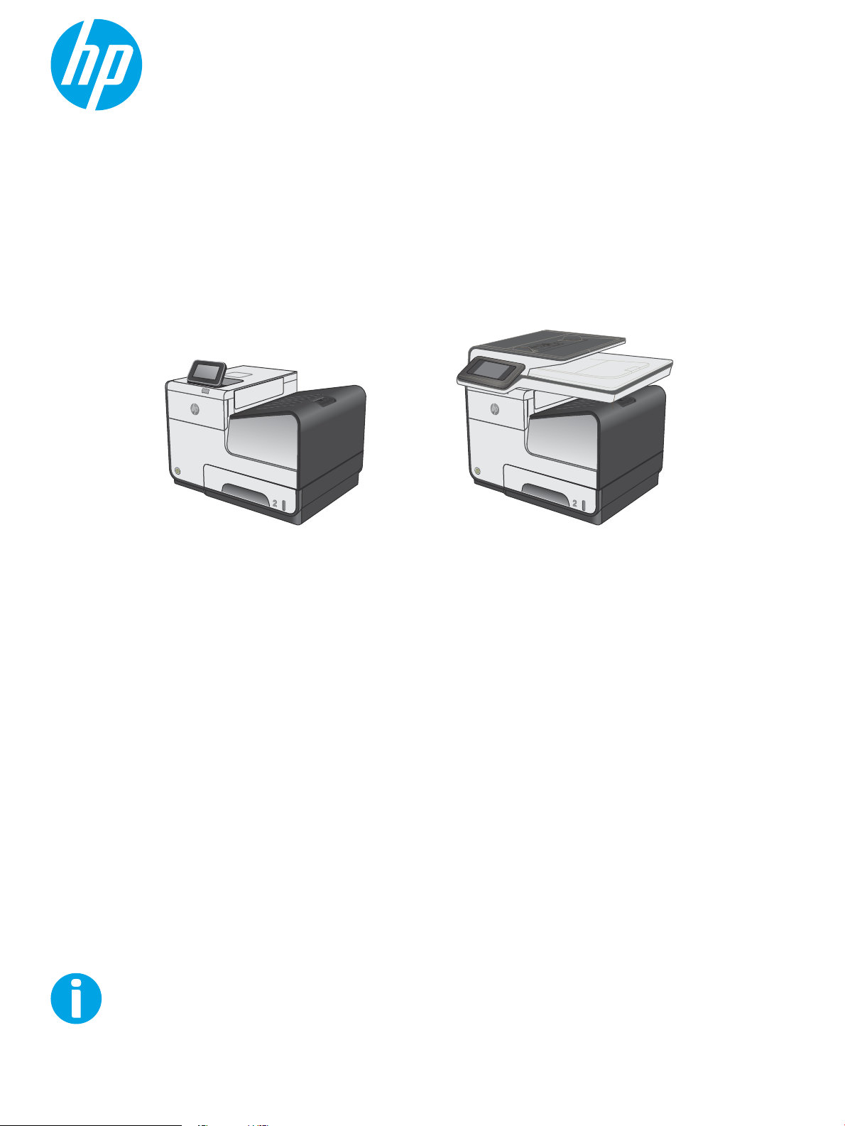
Basic operation
Control panel
Output bin
Printbar
Service sled
Main input tray (Tray 2)
Optional trays (Trays 3 and 4)
Multipurpose tray
(Tray 1)
Ink collection unit
Optical
scan
carriage
Ink cartridges
Function structure
The printer consists of the following components.
Figure 1-1 Main components (352/452 models)
2 Chapter 1 Theory of operation ENWW
Page 13
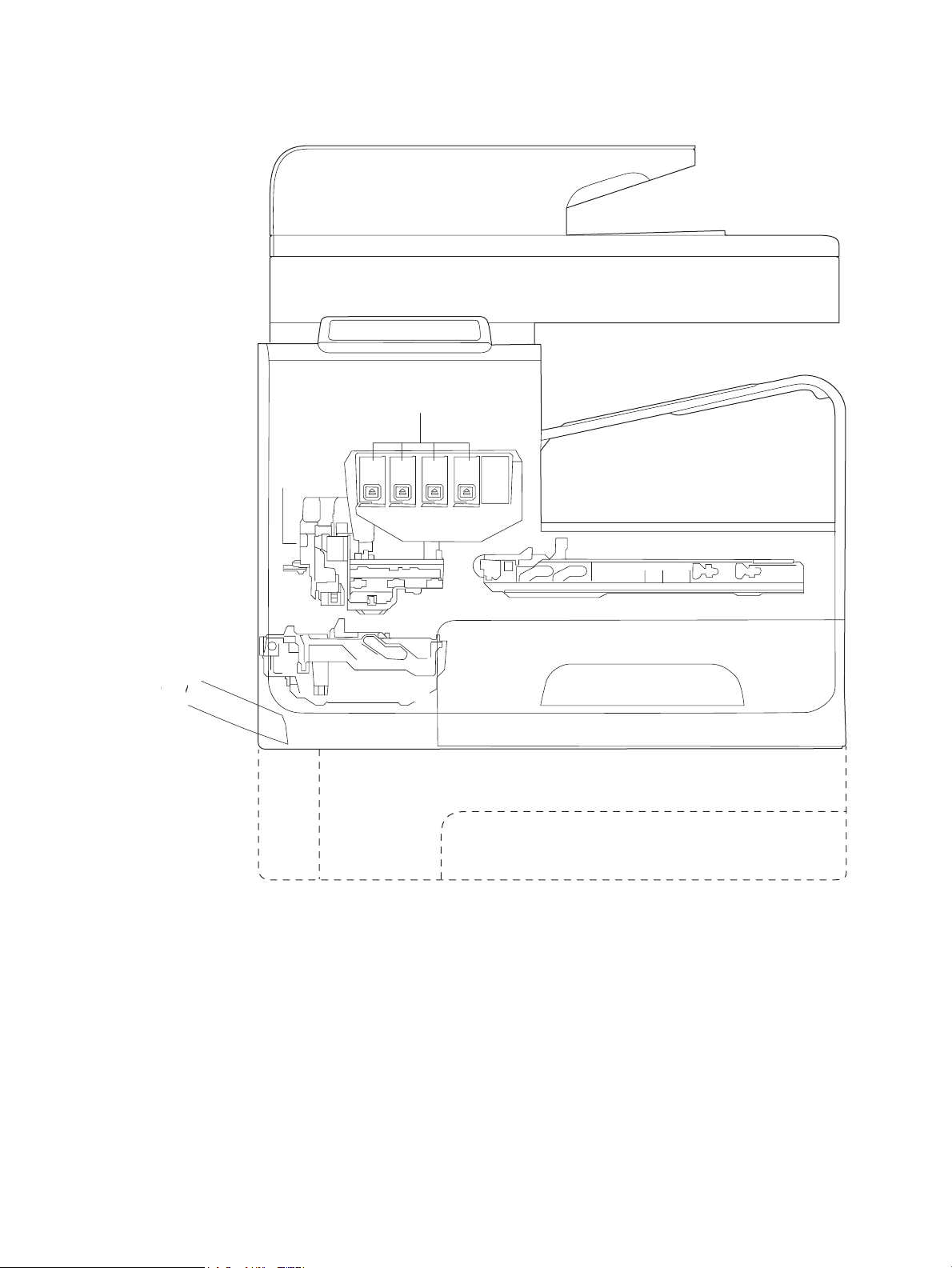
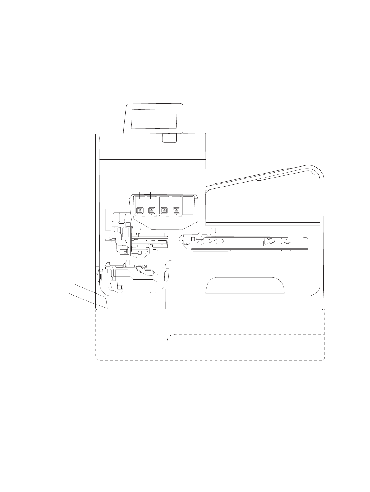
Figure 1-2 Main components (377/477 models)
Document feeder
Scanner
Control panel
Output bin
Printbar
Service sled
Main input tray (Tray 2)
Optional trays (Trays 3 and 4)
Multipurpose tray
(Tray 1)
Ink collection unit
Optical
scan
carriage
p
Ink cartridges
(
ENWW Basic operation 3
Page 14
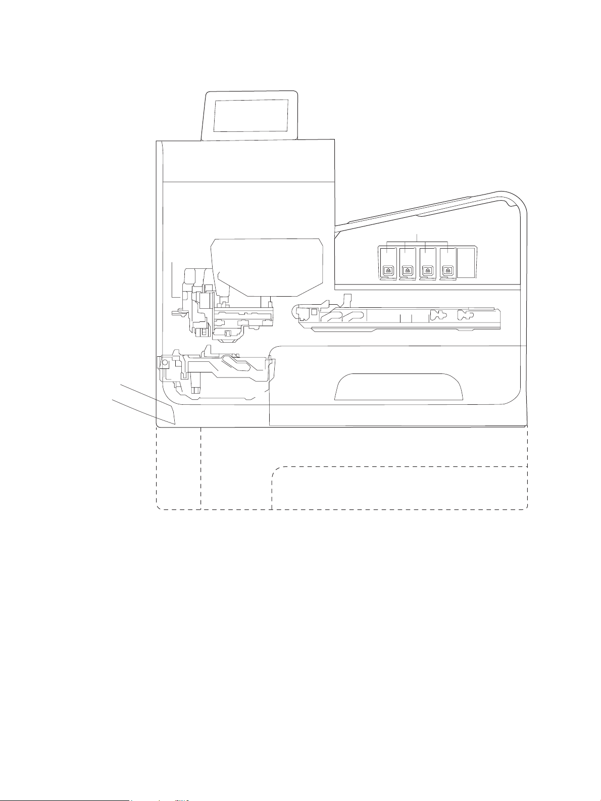
Figure 1-3 Main components (552/P55250 models)
Control panel
Output bin
Printbar
Service sled
Main input tray (Tray 2)
Multipurpose tray
(Tray 1)
Duplex module\
Waste ink module
Optical
scan
carriage
Optional trays (Trays 3 and 4)
Ink cartridges
4 Chapter 1 Theory of operation ENWW
Page 15
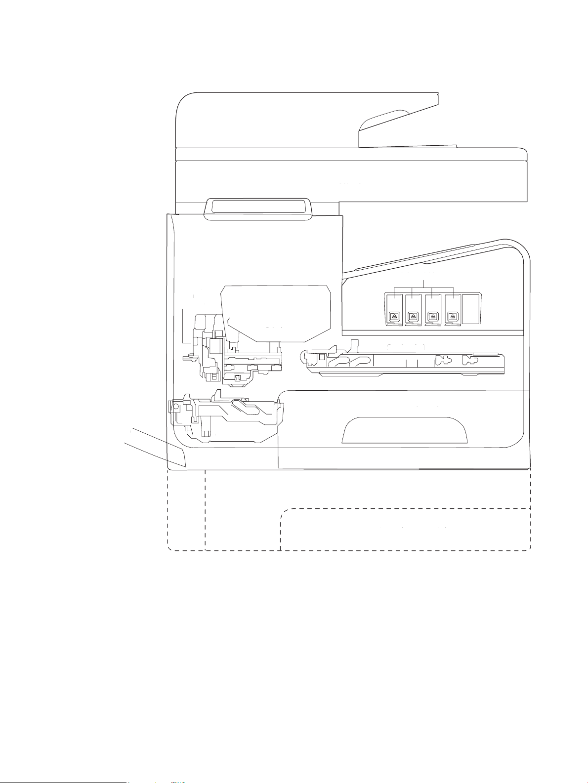
Figure 1-4 Main components (577/P57750 models)
Control panel
Output bin
Printbar
Service sled
Main input tray (Tray 2)
Optional trays (Trays 3 and 4)
Multipurpose tray
(Tray 1)
Duplex module\
Waste ink module
Optical
scan
carriage
Document feeder
Scanner
Ink cartridges
C
ontrol pane
l
O
utput bi
n
Printbar
Se
rvice
sled
M
ain input tray (Tray 2
)
O
ptional trays (Trays 3 and 4
)
Mul
tipurpose tray
(
Tray 1
)
Duplex module
\
Waste ink module
le
O
ptica
l
scan
c
arriage
Document feeder
Sc
anner
nk cartr
idg
es
The printer contains the following systems:
●
Engine control system
●
Print subsystem
●
Paper-handling system
●
Servicing system
●
Aerosol management system
●
Scanner and document feeder system
ENWW Basic operation 5
Page 16

Two elements inuence the printer architecture:
●
The rst is the need to orient the printbar with its active face downwards and statically located above
the print media. This requires the printbar to move vertically to access its active face.
●
The second is producing face-down output. Rather than ejecting the page face-up immediately after the
ink is applied, the printer routes the printed page up and back over the printbar to eject face-down.
Operation sequence
The engine-control system on the formatter PCA controls the operational sequences. The following table
describes durations and operations for each period of a print operation from when the printer is turned on
until the motor stops rotating.
Table 1-1 Operation sequence
Period Duration Purpose
Initial startup and
calibrations
Servicing operations Performed when the printbar is
Print preparation From the time the printer
When the printer is set up for the
rst time from the factory.
entering the capping state after
printing, when leaving the
capping state after a print job is
initiated, or during extended
print jobs.
receives a printer command until
paper enters the print zone.
This period gets the printer ready to print for the rst time.
●
Fluid replacement—The printer ushes the shipping and
handling uid out of the printbar and replaces it with ink.
●
Die alignment—The printer aligns the 10 die on the printbar
active face.
●
Die density leveling—The printer measures and compensates
for the drop variation.
Servicing maintains print quality by removing debris and excess ink
and replacing missing nozzles.
●
Nozzle presence detection—The optical scan carriage detects
and disables inoperable nozzles, and replaces them with
operable nozzles.
●
Printbar servicing—The web wipe on the service sled moves
under the printbar to clean the active face and res the nozzles
into the ink collection unit to clear clogs.
Prepares the printer for a print job.
●
The printbar leaves the capping state as the service sled
moves away from the printbar.
●
If needed, some servicing occurs.
●
The printbar lowers to the printing position. The media type
and printing mode determine the print zone height.
●
The printer picks media from one of the input trays.
●
Every page from Tray 1 is scanned. For Tray 2 and optional
Trays 3 and 4, the printer performs media edge detection after
printing the rst sheet after the tray is loaded. The last sheet
of each job is also scanned if at least ve sheets have been
printed.
●
The printer monitors environmental conditions. The printer
can slow the print speed if conditions are signicantly dierent
than a normal oice environment (23° C (73.4° F), 50% relative
humidity).
●
The formatter PCA processes print data and transmits the data
to the printbar.
6 Chapter 1 Theory of operation ENWW
Page 17

Table 1-1 Operation sequence (continued)
Period Duration Purpose
Printing From the end of the preparation
period until the last sheet is
delivered.
End of print job Performed after the print job is
completed, and continues until
the next job is initiated.
Standby The printer is sitting idle, waiting
for the next print job to be
initiated.
Processes the print job.
●
As the page travels through the print zone, the printbar applies
ink to the page.
●
Simplex print job—the page moves up, over the printbar, and
out to the output bin (face-down).
●
Duplex print job—the page moves up until the trailing edge is
40 mm (1.5 in) past the star-wheel jam reective sensor. The
page reverses direction down through the duplex path and
underneath the ink collection unit. Then, it reenters the print
zone, where the printbar applies ink to the second side.
●
The process continues until all the pages of the print job are
completed. The process can be interrupted by occasional
nozzle presence detection and servicing events, if the job
includes many pages.
This period puts the printer in a state where it’s ready for the next
print job.
●
If needed, some servicing occurs.
●
The printbar moves to the capping position after a short dwell
interval.
●
The service sled moves to cap the printbar.
This period is intended to conserve energy when the printer is
sitting idle. Certain functions might be disabled to save power and
then re-started only when needed. The printer has two sleep
modes:
●
Idle mode—The printbar is capped and the printer is ready to
immediately start a new job
●
Sleep mode—After the printer is inactive for about 10 minutes
(a setting that can be adjusted from the control panel or the
Embedded Web Server), the control panel turns o and the
power LED blinks to indicate the unit is in Sleep mode. All
printer functions are available.
ENWW Basic operation 7
Page 18
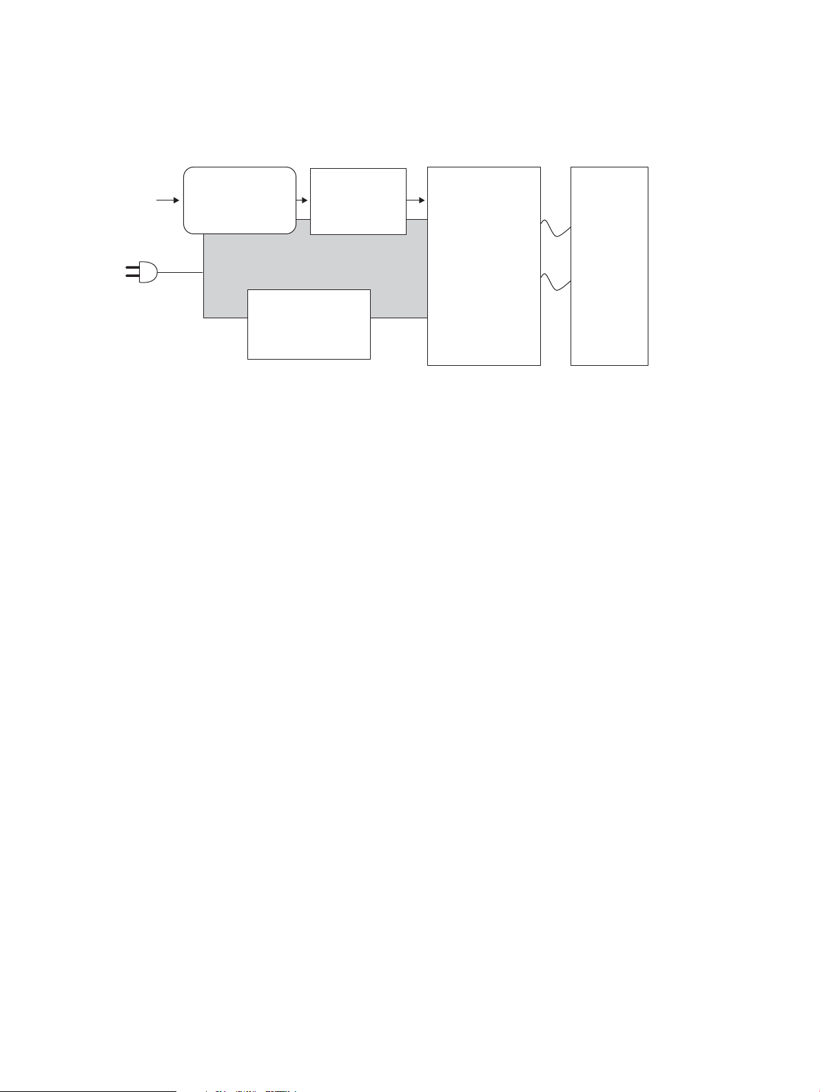
System control
Power supply
Engine control
Motor + sensor drive
Formatter
I/O, PDL, UI control
I/O
Datapath
ASIC +memory
Printbar
40,000 nozzles
Pen I/F
• Pen energy control
• Pen voltage
sequencing
• Signal integrity
• Ink-short protection
• Printhead
interconnects
• Ink supply
The system control coordinates all the other systems, according to commands from the formatter.
Figure 1-5 System control
The system consists of ve major sections.
●
Formatter
●
Data path
●
Engine control
●
Pen interface
●
Power supply
The engine PCA integrates both formatter and engine control electronics onto a single assembly. The wireless
radio unit (wireless models only) plugs into the back of the engine PCA, and the fax connects to the PCA via a
short at-exible cable (FFC).
Formatter and data path
The formatter controller ASIC controls the input/output (I/O) control, the user interface, and the rendering of
page description language les into printer-specic commands.
Input/output (I/O) control
The printers support 10/100 Ethernet, 802.11 wireless (HP wireless direct models), a rear USB host port, a
control panel USB host port (552/P55250/377/477/577/P57750 models), and an analog fax port
(377/477/577/P57750 models). For Ethernet networks, the formatter ASIC uses a separate integrated circuit
(Broadcom 5241) to provide the physical network layer.
The formatter ASIC controls the USB device and USB host as well.
Wireless I/O is provided via a separate radio module.
User interface
The printers contain either a 2-inch (352/452 models) monochrome display or an 4.3-inch (552/
P55250/377/477/577/P57750 models) color graphics display. An icon on the control panel of wireless
models denotes that the wireless feature is enabled. The 552, P55250, 377, 477, 577, and P57750 models
include a walk-up USB host port for connection to thumb drives.
8 Chapter 1 Theory of operation ENWW
Page 19

Formatter digital ASIC
The formatter digital ASIC contains dual ARM CPUs (1.2 GHz and 600MHz) that execute rmware code that
provides high-level device control. The digital ASIC uses a standard PCle interface to pass data to the engine
control ASIC.
Formatter analog ASIC
The formatter analog ASIC generates the system voltage for the formatter, drives the scanner and ADF
motors, manages the real-time clock, and drives the fax speaker. Also, the engine uses this ASIC to drive the
ISS pumps, solenoids, and aerosol fan.
Real-time clock
The real-time clock (RTC) allows the fax module to time-stamp outgoing faxes. In addition, it determines the
elapsed time between printhead and ISS calibration events. The RTC uses a special block inside the engine
analog ASIC, along with a crystal and a battery.
Engine control
The engine controller digital ASIC receives high-level commands from the formatter, and it then provides lowlevel control to the print mechanism. In particular, the engine controller digital ASIC and its rmware control
motors, system sensors, and the printbar. The engine controller analog ASIC integrates motor drivers, voltage
regulators, sensor interfaces, and supervisory circuits.
Engine controller digital ASIC
The engine controller digital ASIC has a high-performance 480 MHz ARM CPU and DSP co-processors that
execute rmware code to provide low-level engine control. It also drives the printbar via 15 high-speed LVDS
transmission lines, which are routed from the engine PCA to the printbar via two large FFC cables. The engine
controller digital ASIC receives pre-rendered data from the formatter digital ASIC over a standard PCle
interface.
When a product has entered sleep mode, many functions of the printer have gone into a low-power mode. If a
print job is received while the product is in sleep mode, the printer will take a short period of time to "wake
up". This can take up to 15 seconds, which will delay the rst page out (FPO) time accordingly.
Engine controller analog ASIC
The engine uses two analog ASICs to generate the system voltages for the engine, drive the engine motors,
control various engine sensors, and monitor printbar power delivery for correct operation.
The engine has seven motors, some of which are shared with other subsystems:
●
Pick motor
●
Feed motor
●
Duplex motor
●
Lift motor
●
Eject motor
●
Sensor carriage motor
●
Aerosol fan motor
ENWW System control 9
Page 20

Each one is a DC motor with encoder feedback, to provide precision servo control. These motors are driven
directly by one of the engine analog ASICs. Small DC motors also are used to drive the ISS pump and the
aerosol fan. There are solenoids that actuate the ejection ap and the ISS priming system.
The printer uses many sensors to track the media as it travels through the paper path. Most of these are
optical REDI sensors, which are used in conjunction with mirrors to sense the presence or absence of paper in
a particular location. These are carefully aligned and calibrated at the factory, so care must be taken when
servicing these sensors. See the Remove and Replace chapter in the repair manual for more details.
Other printed circuit-board assemblies (PCAs)
In addition to hosting the system ASICs, the engine PCA is home to many circuits needed to interface to
sensors and other sub-system components. In some cases, this circuitry is located on a smaller remote PCA
(SLB) to optimize cable interconnects.
●
Humidity sensor—The humidity sensor causes the printer to adjust printing speed if ambient conditions
are outside the optimal humidity range. This sensor is calibrated at the factory to ensure maximum
accuracy.
●
Temperature sensor—The temperature sensor causes the printer to adjust printing speed if ambient
conditions are outside the optimal temperature range. In some printers, this sensor resides on a
separate, remote PCA.
●
Main tray presence sensor—The hall-eect sensor that detects if the main tray is properly engaged
resides on the back of the engine PCA. A small magnet on the back of the main tray actuates the sensor.
If the tray is fully engaged, the magnetic eld strength is suicient to trigger the sensor.
Additionally, the printer includes the following PCAs:
●
Front USB PCA—This PCA governs the control panel USB port.
●
Fax PCA—This PCA governs the printer fax module.
●
Duplex module presence sensor–This hall-eect sensor detects whether the duplex module is properly
seated.
●
Power button PCA—This PCA includes the power button and power LED, as well as interface cables to
the duplex module presence sensor and the MP tray empty REDI sensor.
●
Accessory tray interconnect PCA—This PCA provides communication to optional Tray 3.
●
Pick encoder distribution PCA—This PCA includes the pick motor encoder and the pick motor
interconnect cable.
●
Eject encoder distribution PCA—This PCA includes the eject motor encoder, plus the interconnect cables
to the eject motor and the aerosol fan.
●
Print zone distribution PCA—This PCA joins interconnect cables to the following sensors: separator REDI,
feed motion encoder, main tray empty sensor, Top of Form (TOF) REDI sensor, and the Print zone REDI
sensor.
●
REDI distribution PCA—This PCA includes hall-eect sensors that detect ink cartridge door and left door
positions. It also combines the interconnect cables for the eject REDI sensor, the upper paper path REDI
sensor, the lower paper path REDI sensor, and the eject ap opto ag sensor.
●
Sensor carriage PCA—This PCA includes a carriage motion encoder, a ZIM sensor, and the BDD sensor.
●
Printbar lift encoder distribution PCA—This PCA includes the printbar lift motion encoder and combines
interconnect cables to the printbar lift motor, carriage motor, and eject ap solenoid.
10 Chapter 1 Theory of operation ENWW
Page 21

●
Duplex encoder PCA—This PCA contains the motion encoder for the duplex motor.
●
SHAID PCA—This PCA contains interfaces to the out-of-ink sensors for the ink cartridges, and combines
the interface cables to the acumen PCA, the ISS pump, and the ISS solenoids.
●
Acumen PCA—This PCA contains interfaces to the acumen memory devices for the ink cartridges.
Pen interface (I/F)
The printbar is the key component that dierentiates these printers from other inkjet printers. The
conventional approach is to print a page in horizontal swaths by moving a “scanning” printhead horizontally
xed sheet of paper, advancing the paper a xed amount, and then printing the next swath. With these
over a
printers, the paper moves underneath a xed page-wide printhead in a single smooth motion.
Single pass page-wide printing requires that data and power be delivered to the printbar at a very high rate,
while also maintaining good control of paper position as it moves past the printhead nozzles.
The engine PCA sends power and data to the printbar via two large at exible cables (36 and 38 pins). The
printbar PCA routes power and data to 10 printhead die, which are attached to the PCA using a exible tab
circuit and wire-bonding process.
The printers also contain electronics to control the ink supply station (ISS). The SHAID PCA detects low-ink
conditions. It gauges ink levels by means of electrically sensing the presence of ink and/or ink foam in the Xchamber. The SHAID PCA also collects and distributes electrical signals that drive the push-prime pump(s),
engage the solenoids, and read the ink supply acumen data. All are routed through a single 17-pin FFC from
the SHAID PCA to the engine PCA.
Each ink supply has a memory tag that stores information about its type of ink, the amount of ink remaining,
and other critical data. It uses a special authentication scheme to ensure that only genuine HP supplies are
used and the printer is not damaged by using invalid supplies. Acumen uses a two-line serial bus, which,
along with 3.3 V and ground, is cabled via the SHAID PCA to the engine PCA and the engine control digital ASIC.
Power supply
The power supply module converts 100-240 VAC to 34 VDC to power the system. The power supply module
has a sleep mode that reduces power consumption in system low-power modes. When in its sleep mode, the
power supply generates less than 4 W.
The power supply module supplies 34 V to the engine PCA. The power supply module has two operating
modes, depending upon the state of its nSLEEP input pin:
●
Printing: = up to 13 W ( nSLEEP = high logic level)
●
Sleep mode: = < 4 W ( nSLEEP = low logic level)
The power supply is a self-contained module that can be replaced if it is determined to be defective (see the
Remove and Replace chapter of the Repair Manual).
To ensure safe operation, the power supply will “latch o” if a persistent over-current fault condition exists.
This would typically be caused by a short-circuit from 34 V to ground in the printer. Less severe faults can
cause the power supply to latch o, if present for an extended period of time, or if the printer is operated
above the recommended operating temperature range.
NOTE: In some countries/regions, the printer is equipped with a high-voltage power supply in order to
prevent power supply unit failures due to over-voltage conditions.
ENWW System control 11
Page 22
Print subsystem
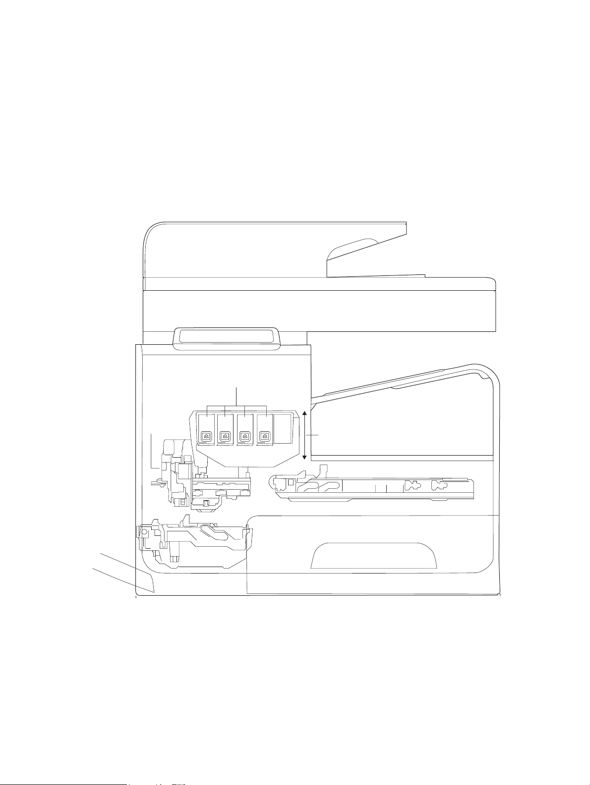
Printbar lift
Ink cartridges
Printbar
Optical
scan
carriage
The print subsystem includes the following components.
●
Printbar
●
Printbar lift
●
Ink cartridges
●
Optical scan carriage
Figure 1-6 Print subsystem components (300/400 series)
12 Chapter 1 Theory of operation ENWW
Page 23
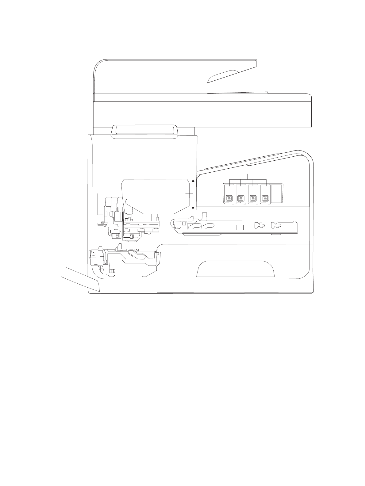
Figure 1-7 Print subsystem components (500 series)
Printbar
Optical
scan
carriage
Ink cartridges
Printbar lift
Printbar
The printbar’s fundamental purpose is to convert the digital ring instructions from the printer electronics
into properly formed and timed microscopic drops of the four ink colors. The printbar spans the full width of a
letter/A4-size sheet (216 mm (8.5 in)), which allows the printbar to be statically positioned within the printer
and have the media move underneath it, printing the entire page in a single motion.
ENWW Print subsystem 13
Page 24
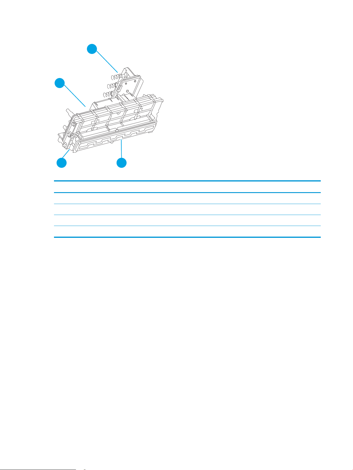
Figure 1-8 Printbar components
1
4
23
Table 1-2 Printbar components
Item Description
1 Ink cartridge connections
2 Thermal inkjet (TIJ) die array
3 Data/power ow and regulation
4 Inkow channels and pressure regulation
The printbar has a xed array of 10 thermal inkjet (TIJ) die oriented in two staggered rows. Each die contains
more than 1,000 nozzles for each of the four ink colors—black (K), cyan (C), magenta (M) and yellow (Y).
Behind the die array are the ink ow channels and pressure regulation mechanisms that supply the die array
with ink at the proper pressure and ow. The die must also be fed power and data at the appropriate levels
and rates, which is the function of the onboard electronic circuitry. Finally, situated at the top of the printbar,
there are four ink cartridge receptacles, one for each color. These cartridges are linked by ow connections to
the rest of the printbar and supply the ink necessary for its operation.
A sensor technology called back-scatter drop detect (BDD) monitors printbar health and calibrations. This
system looks at the reection of the miniscule drops in ight, and then passes these signals through highspeed, high-gain, bandpass lters. A complex articial intelligence (AI) system decides which drop ejectors are
currently out of specications, and which are not.
After the AI system determines which drop ejectors are out of specication, the printer compensates for
them. Some ejectors use neighboring nozzles and at times even tiny amounts of other inks—whichever
combination of methods necessary to deliver the best print quality possible at that moment. In some cases,
fully half of the nozzles can be “out” without a noticeable degradation in quality. The compensation is done in
real time with a dedicated high-speed DSP. The system can scan portions of the system after print jobs, but it
is fully interruptible by new, incoming print jobs.
Printbar air management system
The printbar uses a passive air gain management system. Air can enter the printbar from the following
sources:
14 Chapter 1 Theory of operation ENWW
Page 25

●
Die outgassing (from air in the ink)
●
Air entering nozzles due to temperature or pressure variations
●
Air entry through the printbar structure
●
Air entry through the nozzles due to shipment vibration
Air that enters the printbar is warehoused. There is no mechanism to remove the air in the eld. Of the
various mechanisms for air entry, the rst three are generally benign, and rarely cause issues during the
expected life of the printer. The fourth mechanism generally occurs during shipment. New printers are
shipped with the printbar taped—which limits the amount of air gained. If the printbar isn’t well restrained
during shipment, then air gain can be
air gain can be reduced either by ensuring that the printer stays on its base, or that the printbar is restrained.
Both would be best.
Printbar lift
The printbar lift is responsible for positioning the printbar within the printer and moving it up and down as
required. This vertical motion is both to establish proper spacing to the paper during printing, and to raise it
to either access the active face or perform necessary calibrations.
During printing, the lift mechanism sets the printbar height and paper height depending on the type of paper.
Ink cartridges
signicant. If the printer is shipped after removal of the printbar tape,
These printers have new, state-of-the-art pigmented inks. They are ltered using proprietary processes to
prevent printhead contamination. These inks are designed to produce optimal print quality on ColorLok oice
papers, but also produce very good print quality on regular oice papers and specialty paper.
Optical scan carriage
The optical scan carriage has optical sensors used for calibration. Its motion is along the long axis of the
printbar. These sensors are used by a number of printer calibration features that are important for proper
subsystem function. The BDD sensor is located on the optical scan carriage.
Print system operational states
The print subsystem has a number of distinct operational states besides active printing.
Startup
As it comes from the factory, the printbar is initially lled with an inert ink-substitute called Shipping and
Handling Fluid (SHF). This uid, essential for the manufacture and transportation of the printbar, must be
ushed and replaced with actual ink. This is accomplished during the Startup phase. The ushing process
automatically commences when ink supplies are inserted and the unit is powered up for the rst time. The
SHF is removed by sustained printbar operation and replaced by ink from the supplies. The process
terminates once all the SHF has been ushed from the printbar.
Special host supplies are supplied with the printer prior to its rst use. These supplies contain additional ink
so that there will be 100 percent ink level after the SHF is replaced with ink. These supplies can be used only
to initialize the printer. You cannot use them in another printer that has been initialized.
NOTE: The initial startup time is noticeably longer than the following regular startup times.
ENWW Print subsystem 15
Page 26

Die alignment
Since 10 die comprise the printbar active face, each with associated positional tolerances, an active
calibration must be performed to prevent errors and allow a uniform ink application to the paper (without any
gaps or overlaps between adjacent die). This die alignment is done by printing a special diagnostic image on a
sheet of paper and then scanning it with the optical scan carriage. Die alignment is performed as part of
initial unit startup, and can be performed manually as part of the print quality recovery tool.
Die density leveling
Tolerances are also associated with the drops red by the individual printbar die. Another active calibration
measures and compensates for these variations to produce a visually uniform ink application to the paper.
Another set of diagnostic images is printed and scanned by the optical scan carriage to achieve this die
density leveling. Die alignment and die density leveling are usually paired together.
Nozzle presence detection
In printing, since all the ink is applied in a single smooth motion of the paper past the printbar, any inoperable
nozzle can show up as a noticeable streak. The operational state of each of the thousands of nozzles on the
printbar is periodically measured. The printbar lift raises the printbar, and the BDD assembly on the optical
scan carriage watches for drop presence as each nozzle is red. Inoperable nozzles are turned o and other
operable nozzles are used on subsequent printed pages to apply the missing ink. Nozzle presence detection is
fully interruptible by new, incoming print jobs.
Media edge position detection
The printer uses a learning algorithm to dene media center as a function of input source—Tray 1, Tray 2, or
optional Trays 3 and 4. The edge scan is located downstream of the print zone. As paper is scanned, the
media center database is updated. The image is registered to the page using the media center database.
Servicing and capping
When in the capped state, the printbar is fully raised, the service sled is positioned underneath, and the
printbar cap is engaged against the printbar active face. Servicing—the cleaning of the active face and the
ring of the nozzles—can occur either during Sleep2 mode or after extended time in storage. It can also occur
during extended print jobs.
Printing
The printing state begins by the printbar leaving the capping state, and lowering to the printing position after
the service sled moves out of the way. At the same time, a sheet of paper is picked from one of the three trays
and the leading edge staged at the entrance to the print zone. Once the print data has been sent, the sheet of
paper feeds at a constant velocity through the print zone and the printbar applies the ink.
In the case of one-sided printing, the inked sheet is moved up, over and out to the output tray. For two-sided
printing, the sheet is moved until its trailing edge is past the merge to the vertical path. The sheet is then
reversed down through the duplex path underneath the ink collection unit, and reintroduced into the print
zone for inking of the second side.
This process continues until all the pages of the print job are completed. If the print job is large enough, it can
be interrupted by servicing processes.
16 Chapter 1 Theory of operation ENWW
Page 27
Paper-handling system
The paper-handling system moves paper through the printer according to commands from the formatter.
The following gures show the printer paper path.
Figure 1-9 Paper-handling system paper path (300/400 series)
ENWW Paper-handling system 17
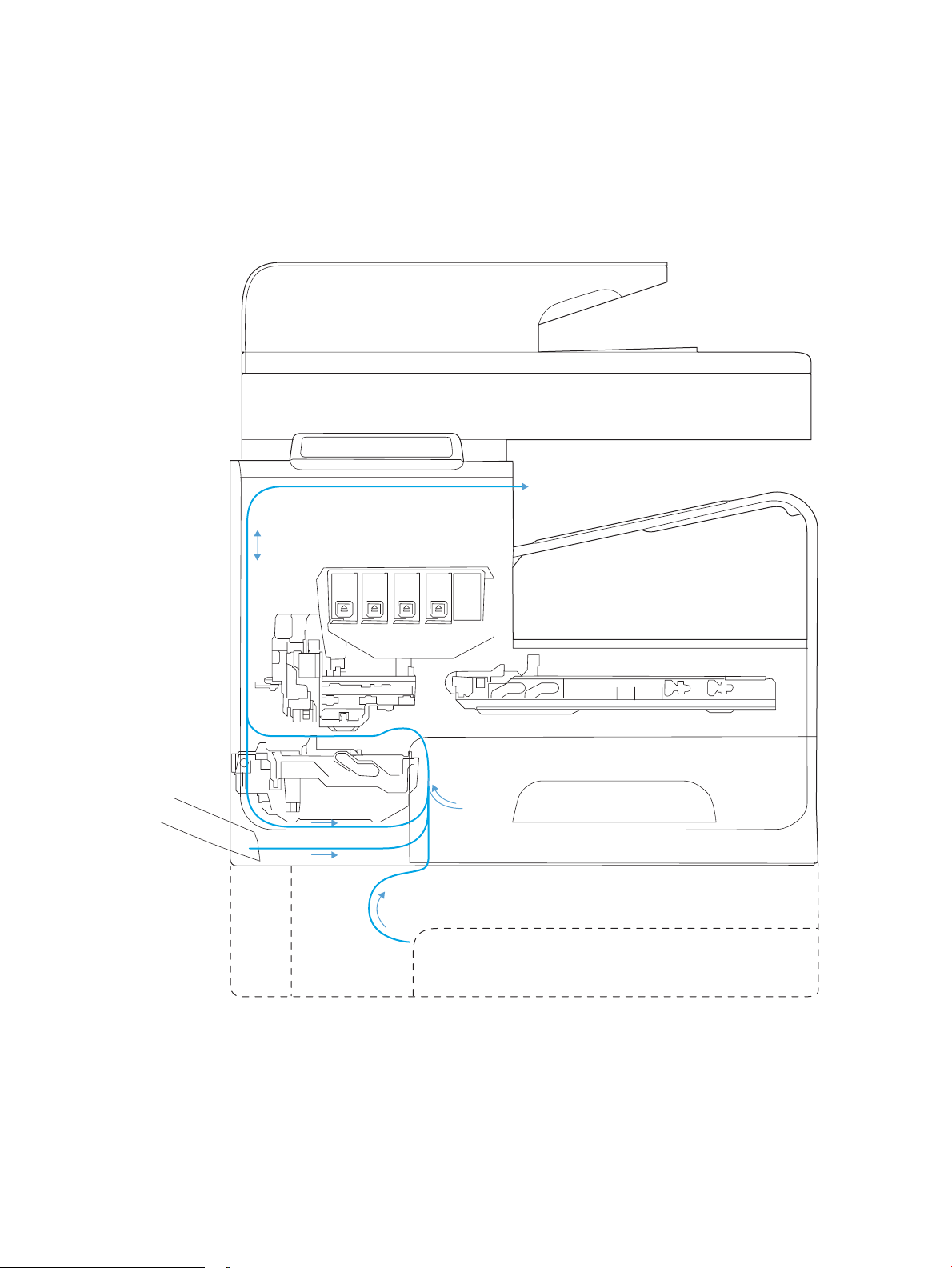
Page 28
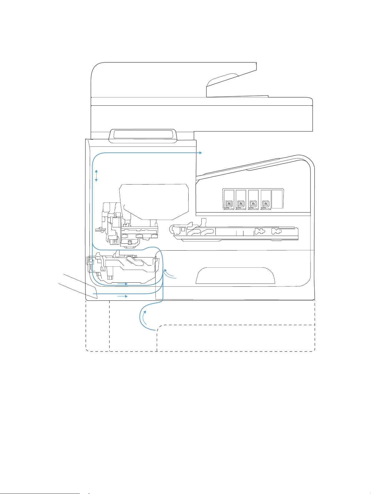
Figure 1-10 Paper-handling system paper path (500 series)
The paper path consists of the following major components:
●
Two integrated input trays plus one optional accessory tray
●
Four motors and a solenoid plus two more motors in the accessory tray
●
Duplex module
●
Sensors placed throughout the device, including the paper trays
18 Chapter 1 Theory of operation ENWW
Page 29
●
1
2
3
13
14
15
16
17
18
19
20
21
22
23
24
12 11 10 89
999997
6 45
Multiple feed rollers, pinch rollers, star wheels, and media guides
●
Transmission components (gears, shafts, levers, swingarms) that interface with other subsystems such
as the printbar and service sled.
Components of the paper path move the paper from the input tray to a position 1 to 2 mm (.04 to .08 in)
underneath the printbar, and then deliver the printed result to the output tray. The combined orientations and
actions of the printbar, the printbar lift, and the paper path establish the print-zone, where the ink drops
move from the active face of the printbar to the paper.
The following gures show the printer sensors.
Figure 1-11 Printer sensors (300/400 series)
ENWW Paper-handling system 19
Page 30
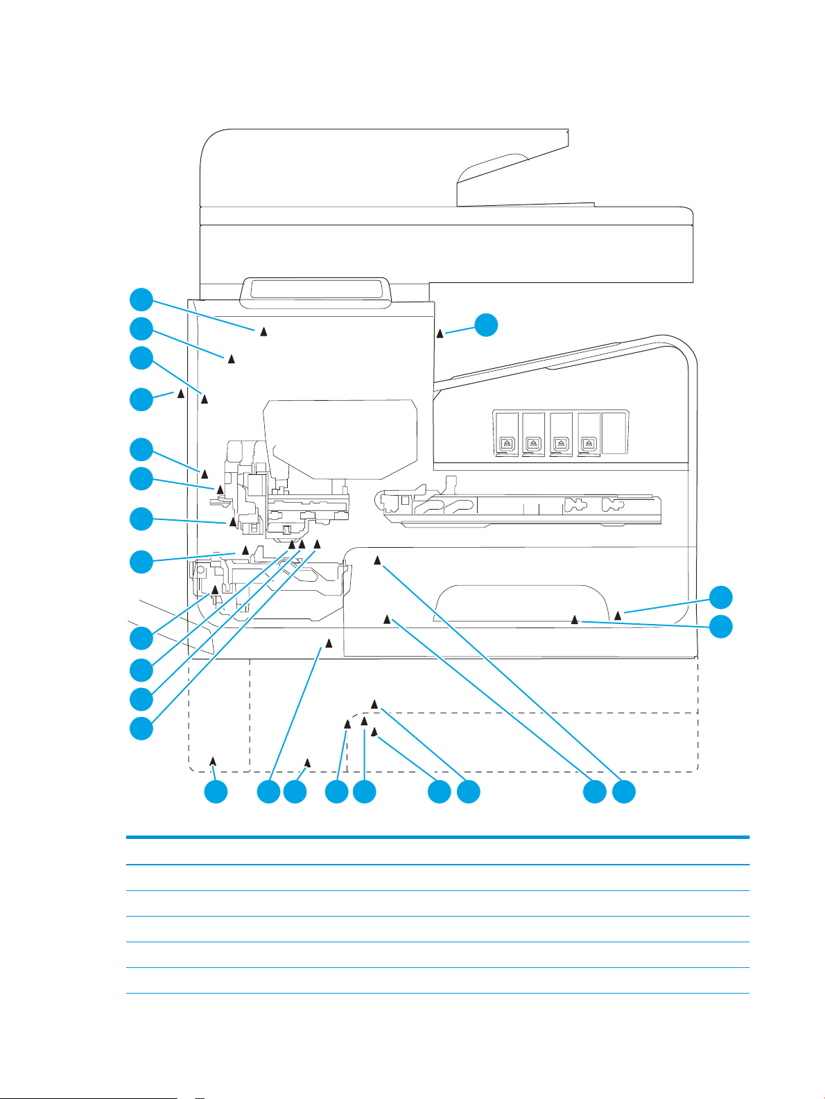
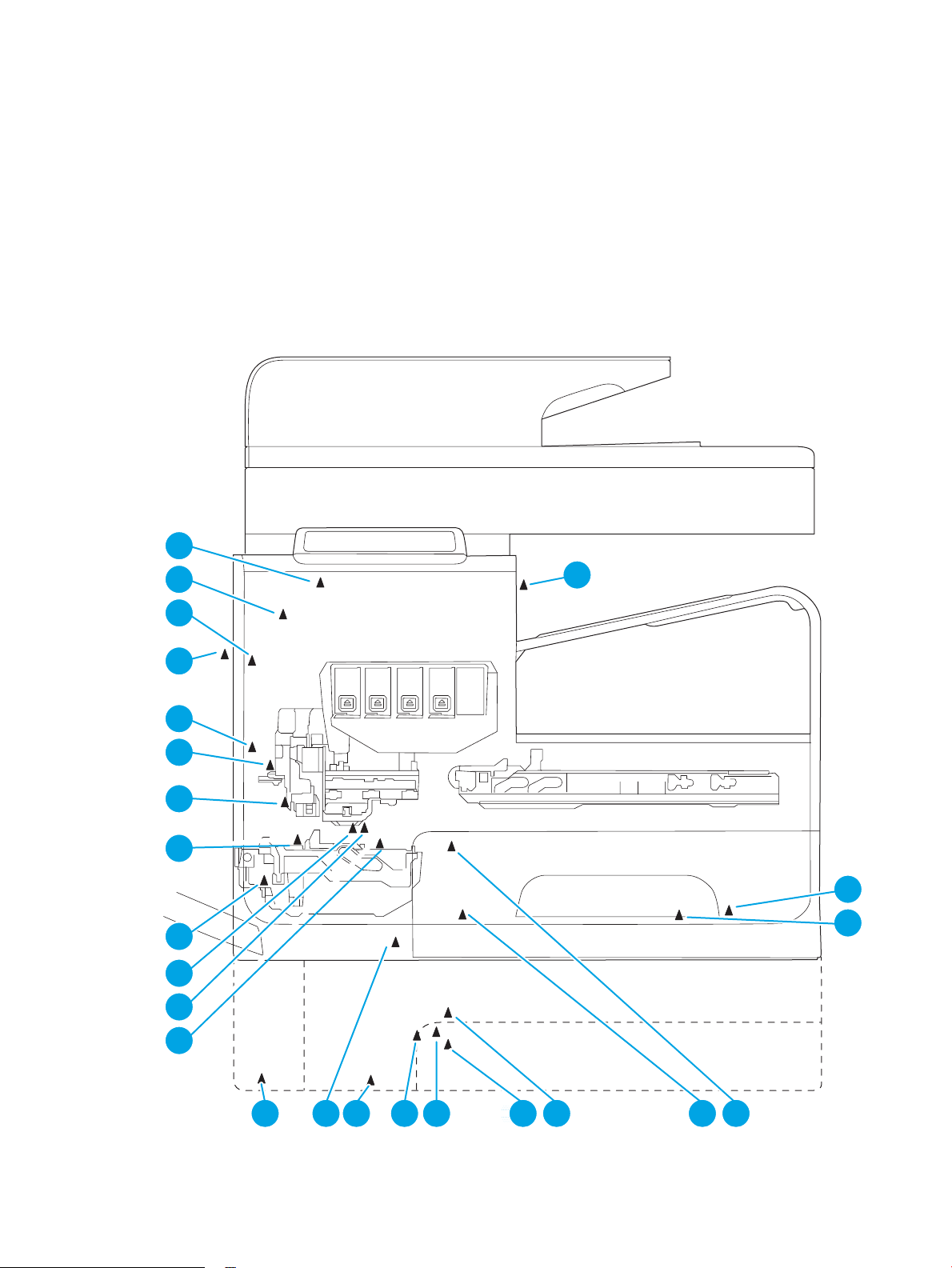
Figure 1-12 Printer sensors (500 series)
1
2
3
13
14
15
16
17
18
19
20
21
22
23
24
12 11 10 89 999997 6 45
Table 1-3 Printer sensors
Item Description Item Description
1 Output ap jam sensor 13 Top of Form (TOF) REDI sensor (located on platen)
2 Ambient temperature sensor 14 Feed roller encoder
3 Ambient humidity sensor 15 Feed roller home sensor
4 Tray 2 pickup tire home sensor 16 Duplex module presence sensor
5 Tray 2 tray presence sensor 17 Print zone REDI sensor (located on platen)
20 Chapter 1 Theory of operation ENWW
Page 31

Table 1-3 Printer sensors (continued)
Item Description Item Description
6 Tray 3 pickup tire home sensor 18 Back-scatter drop detect sensor
7 Tray 3 paper presence sensor 19 Print calibration/media edge detect sensor
8 Tray 3 separation sensor 20 Lower paper path REDI sensor
9 Tray 2 paper presence sensor 21 Left door open sensor
10 Tray 3 tray presence sensor 22 Upper paper path REDI sensor
11 Tray 1 paper presence sensor 23 Ink supply door open sensor
12 Tray 3 cleanout presence sensor 24 Eject REDI sensor
There are several motors in the printer for pick, feed, duplexing, printbar lift, delivery, and the scanning
sensor carriage.
ENWW Paper-handling system 21
Page 32

Figure 1-13 Paper-handling-system motors (300/400 series)
1
234
5
6
7
8
22 Chapter 1 Theory of operation ENWW
Page 33

Figure 1-14 Paper-handling-system motors (500 series)
1
234
5
6
7
8
Table 1-4 Paper-handling system motors
Item Description
1 Eject (or output drive) motor
2 Tray 2 pickup motor
3 Tray 3 pickup motor
4 Duplex Tray 1 motor
5 Tray 3 feed motor
ENWW Paper-handling system 23
Page 34

Table 1-4 Paper-handling system motors (continued)
Item Description
6 Feed motor
7 Optical carriage motor
8 Printbar lift motor
Input trays
The printer comes standard with two input trays, and also accepts two accessory trays.
●
●
50-page multipurpose (MP) tray—Tray 1: The tray shares a motor with the duplex module and has only
one sensor. It is a reective (REDI) sensor that determines if media is present in the tray. The feed roller
reective REDI sensor determines if a sheet of media is successfully picked from the tray.
500-sheet letter/A4 size main tray—Tray 2: The tray has a pick motor, which is also moves the service
sled. Similar to the accessory tray, both the main tray motor and the duplex MP tray motor will operate
at the same time when picking paper from the main tray. The main tray has three sensors:
◦
A hall eect sensor determines if the tray is closed.
◦
A ag/opto sensor determines if there is media in the tray.
◦
A ag/opto sensor determines if the pick roller is in home position.
The feed roller jam sensor is used to determine if a sheet of media is successfully picked from the main
tray.
●
Two optional 500-sheet legal size accessory trays—Trays 3 and 4: These optional trays each have two
motors, one for picking paper and one for the turn roller. This roller receives paper from the pickup roller
and transfers it to the multipurpose tray ITR, that is driven by the duplex module/MP tray motor. Both
the accessory tray motor and the duplex module/MP tray motor operate at the same time when picking
paper out of the accessory tray.
The accessory trays have the following sensors:
◦
A hall eect sensor determines if the tray is closed.
◦
A ag/opto sensor determines if there is media in the tray.
◦
A ag/opto sensor determines if the pickup roller is in the home position.
◦
A hall eect sensor determines if the left door is closed.
◦
A separation sensor determines if the printer successfully picked media.
Paper path zones
The printer paper path includes the following elements:
●
Deskew buckle
●
Print zone
●
Duplex
24 Chapter 1 Theory of operation ENWW
Page 35

●
1
2
4
5
3
Output
●
Eject
Figure 1-15 Paper path zones (300/400 series)
ENWW Paper-handling system 25
Page 36

Figure 1-16 Paper path zones (500 series)
2
1
5
4
3
Table 1-5 Paper path zones
Item Zone Description
1 Deskew buckle This is the area between the turn roller and feed roller. All paper passes through this zone. During the
deskew operation, the duplex module/MP tray motor rotates forward, driving the paper into the feed
roller nip while the feed roller is not moving. The feed roller REDI sensor determines the leading edge
for accurate deskew buckle size, detects jams, and senses whether the tray successfully picked paper.
26 Chapter 1 Theory of operation ENWW
Page 37

Table 1-5 Paper path zones (continued)
Item Zone Description
2 Print zone This is the path between the feed roller and output pinch 1 roller. The feed roller, which has an analog
3 Duplex By opening the left door, the duplex module can be removed to clear jams. The duplex module also
4 Output The output path begins at output pinch roller 1 and continues to output pinch roller 5. Four REDI
quadrature encoder, precisely controls the paper in the paper feed direction . In the vertical direction, a
combination of the platen, feed roller, and output pinch roller 1 controls the paper. The user can rotate
the platen down for jam access after removing the duplex module.
The print zone contains no paper path sensors. If a jam occurs in the print zone, it is not detected until
the leading edge of the paper is determined to be “late” in reaching the jam sensor in the output path.
When a user pulls on jammed paper in the print zone that is still partially in the feed roller nip, the
servo control detects a slight movement of the feed roller and assists the user by applying a forward
torque to the roller. Also, the motion control system disengages the duplex module rectier (swing
arm) so that the turn roller can spin freely. This feature reduces the pulling force needed by the user
and therefore reduces the chance of leaving torn pieces of paper in the path—especially in the deskew
buckle zone.
serves as an ink-collection unit for the printbar and will expose the user to waste ink when it is
removed. Therefore, the duplex module contains warnings to not touch certain areas.
When the user pulls on jammed paper from the duplex module (or any of the trays) that is partially in
the feed roller nip, the servo control detects a slight movement of the feed roller and assists the user
by applying a reverse torque to the feed roller and disengages. Also, the motion control system
disengages the duplex module rectier so the turn roller can spin freely. This feature reduces the
pulling force needed by the user and therefore reduces the chance of leaving torn pieces of paper in
the path—especially in the deskew buckle zone.
In order for the printer to determine the duplex module's presence, the duplex module has a magnet
that triggers a hall-eect sensor mounted to the structure.
sensors in this path detect leading and trailing edges and jams.
The feed motor drives the rollers in the output path, except output pinch roller 5. All the pinch rollers
in the output and exit path are star wheels to prevent roller tracking on wet/damp ink. However, the
turn roller pinch is solid and has a high amount of force for deskew buckle formation. Also, the feed
motor drives all output shafts except shafts 5 and 6.
The REDI dry path lower, REDI dry path upper, and eject jam REDI sensor in the output path all track
the leading and trailing edges of paper.
The outer and top portions of the vertical path are formed by paper guides molded in and attached to
the left door. The left door can be opened for jam clearance and has a hall-eect sensor to determine
if it is closed. Also when the left door is opened, drive rollers that form pinches 3 and 4 disengage from
the feed motor for safety purposes.
5 Eject The eject portion of the paper path includes the zone from output pinch roller 5 to the eject ap.
The eject motor powers output pinch roller 5 and eject pinch roller 6.
The eject ap has 3 positions:
●
Closed when not printing.
●
Partially open for heavy ink printing in dry environments to limit severe curl.
●
Open for all other printing. This position controls moderately curled paper.
The ap is opened and closed by a torque clutch on the eject roller shaft. The ap also has a locking
feature that is controlled by a solenoid. In order for the door to open all the way or move between
positions, the solenoid must be actuated.
ENWW Paper-handling system 27
Page 38

Servicing system
Duplex module/
Ink collection unit
Service sled
The servicing system comprises the service sled, which maintains print quality by wiping debris and ink o
the print nozzles, and the ink collection unit, where maintenance ink is deposited.
Figure 1-17 Servicing system components (300/400 series)
28 Chapter 1 Theory of operation ENWW
Page 39

Figure 1-18 Servicing system components (500 series)
Service sled
Duplex module/
Ink collection unit
ENWW Servicing system 29
Page 40

Service sled
1
2
3
4
Figure 1-19 Service sled components
Table 1-6 Service sled components
Item Description
1 Service sled cap
2 Service sled wiping surface
3 Service sled web fabric loop
4 Printbar support posts
The service sled system keeps the printbar nozzles ring correctly throughout the life of the printer as it
performs the wiping and capping functions.
●
The wiping function cleans the nozzles of ink residue and particulates.
●
The capping function keeps the nozzles moist during storage and when the printer is idle.
The service sled system uses the pick drive system (a component of the paper path) for horizontal motion to
perform its functions.
To perform the wiping function, the printer moves the service sled underneath the printbar (which is elevated
from the print position) so that the web fabric makes contact with the ink nozzles. The web fabric is a looped
belt that advances after every wipe. Since the belt is a nite loop, it will eventually reuse previously used
material. The web advances when the web wipe module moves to the right and out of the print zone. A
mechanism located on the rear wall of the unit triggers the advance mechanism..
To perform the capping function, the service sled moves underneath the printbar (which is elevated from the
print position), allowing the rubber cap to seal the print nozzles from the environment.
30 Chapter 1 Theory of operation ENWW
Page 41

Transmission system
The pick/service motor uses a multi-state transmission to power the following three functions:
●
Move the service sled
●
Pick paper from the main tray
●
Lift the main tray paper stack
The transmission has the following states:
●
Service sled (forward/reverse)
●
Pick (forward direction)/tray lift (reverse direction)
Printbar movement to a specic location releases the transmission lock, and enables the pick/service motor
to select the transmission state. The general location of the transmission parts is in Figure 1-20 Transmission
components, rear view on page 31.
NOTE: The transmission components are behind the main PCA electronics and are diicult to access.
Figure 1-20 Transmission components, rear view
The printer will not function with the transmission in the main tray pick/main tray lift state if the service
station has been manually capped.
Reusing caps or pushing the caps too far onto the printbar lift guide rods while servicing the printer can result
in the transmission not shifting reliably.
ENWW Transmission system 31
Page 42

Components
Service Station (PHSA)
Service Station
Drive Shaft (PHSA)
Link Pivot Arm
Shift Swing Arm
Pick Shaft (LPP)
Lower Swing Arm
MT Lift
Transmission (LPP)
Encoder PCA
Upper
Swing Arm
Belt
Motor
Figure 1-21 Transmission main components
States
1. State 1–Main tray lift
●
Link pivot arm and shift swing arm in locked
position
●
Upper swing arm down, engaged with lower
swing arm
●
Lower swing arm down, engaged with main
tray lift transmission
●
Printbar either up or down
2. State 1–Main tray pick
●
Link pivot arm and shift swing arm in locked
position
●
Upper swing arm down, engaged with lower
swing arm
●
Lower Swing arm up, engaged with pick shaft
●
Printbar either up or down
32 Chapter 1 Theory of operation ENWW
Page 43

3. State 1–Mid - Switch
●
Link pivot arm and shift swing arm in unlocked position
●
Upper swing arm in mid switch position
●
Printbar in middle position
4. State 2–Service Station
●
Link pivot arm and shift swing arm in locked
position
●
Upper swing arm up, engaged with service
sled drive shaft
●
Printbar either up or down
ENWW Transmission system 33
Page 44

Aerosol management system
Printbar
Platen
Duct
Duplex
module
Absorbers
Spit
Roller
Aerosol filter
Aerosol blower
Service ink capture (in duplex module)
Paper
The aerosol management system consists of a fan module and lter box to keep ink aerosol from building up
inside the printer. The following gure shows the service ink and aerosol capture system components.
Figure 1-22 Aerosol management process
In between pages, printed aerosol is drawn though the platen openings. Service ink travels directly through
the platen, impacting and collecting on the spit roller. Aerosol from the service spitting is also collected via
the same system. Service ink collects in the duplex module, and a porous lter element captures the aerosol
as aerosol-laden air passes through it. The aerosol blower mounted to the lter housing creates the air
motion (suction—lower pressure—in the print zone).
Most of printbar servicing ink (maintenance ink) is captured by the spit roller and scraped into the bottom of
the bucket on the duplex module. The service ink spit roller is indexed slowly by the motion of paper though
the printer, specically driven by the swingarm and turn-roller gear train, with power provided by the duplex
motor.
The printer purges the printbar of its shipping uid at initial startup, and then absorbers in the base of the
duplex module collect the uid. These absorbers allow much of the initial water to evaporate from the
shipping uid over time. Also, they allow service ink coming into contact with the absorbers to leach some of
their uids into them, assisting with drying and thickening of the sludge.
The blower remains active as long as the printbar is uncapped, and it continues to operate for a few seconds
after capping is complete.
34 Chapter 1 Theory of operation ENWW
Page 45

Figure 1-23 Aerosol management system components
1
2
3
4
Table 1-7 Aerosol management system components
Item Description
1 Blower
2 Aerosol lter housing
3 Duplex module/ink collection unit
4 Platen
ENWW Aerosol management system 35
Page 46

Document feeder system (377/477/577/P57750 models)
23
1
4
5
6
7
8
9
10
11
Document feed system
This section describes the following:
●
Rollers and sensors in the document feeder
●
Document feeder operation
●
Deskew operation
The printer supports single-pass electronic duplexing (e-duplex) copy jobs. Two separate scan modules scan
the front-side and back-side of an e-duplex copy job page in a single pass through the document feeder.
Rollers and sensors in the document feeder
The document feeder contains the following rollers and sensors:
Figure 1-24 Document feeder rollers and sensors
Table 1-8 Document feeder rollers and sensors
Item Description
1 Pre-pick Roller
2 Document ag
3 Separation roller
4 Pre-scan feed roller
5 Pre-scan pinch roller
6 TOF ag
7 E-duplex sensor
8 Post-scan feed roller
9 Post-scan pinch roller
10 Post-scan drive O-ring
11 Post-scan kicker roller
36 Chapter 1 Theory of operation ENWW
Page 47

Document feeder operation
1
2
3
Following is the basic sequence of operation for a document feeder job:
Figure 1-25 Document feeder operation
1. When the original pages to be copied are loaded in the document feeder input tray, the document ag
(callout 1) activates (state switches to 1). A Document loaded message appears on the control panel.
With this ag activated, the document feeder becomes the default copy or scan source. This ag
remains activated until all pages feed through the document feeder.
2. When copy or scan is initiated, the pick system engages and begins feeding the rst page. The leading
edge of the page triggers the TOF ag (callout 2) (state switches to 1) and the page feeds through the
scan-zone.
3. The atbed scan sensor collects the image of the front of the page. For duplex or two-sided scans, the
e-duplex scan sensor (callout 3) collects the scanned image of the back of the page. For a multiple-page
document, the document ag (callout 1) remains triggered (state remains at 1).
4. The trailing edge of the rst page disengages the TOF ag (callout 2) (state switches to 0). The leading
edge of the next page engages the TOF ag (callout 2) (state switches to 1), initiating the scan of the
second page. All of the originals feed through the document feeder with the leading and trailing edges
of the pages engaging and disengaging the TOF ag in this manner.
5. When the last page feeds through the document feeder, the document ag (callout 1) disengages (state
switches to 0). This signals that the job is complete. After the TOF ag (callout 2) sees the last trailing
edge (state switches to 0), the last sheet ejects, the pick system lifts, and the scan or copy job
completes.
6. A pick failure occurs if the page doesn’t reach the TOF ag (callout 2) within a certain time frame. If this
failure occurs, the pick system will make two more attempts to pick the page before displaying a Reload
original message on the control panel.
7. The TOF ag (callout 2) expects to see the trailing edge of the page within approximately 43.18 cm
(17 in) from the beginning of the page. If this does not happen, a document jam message displays on the
control panel.
ENWW Document feeder system (377/477/577/P57750 models) 37
Page 48

Deskew operation
Sliding side guides on the document feeder input tray ensure that the paper stack is correctly aligned at the
center of the input tray when paper is loaded in the tray. The correct position of the loaded paper is parallel
with the direction of travel into the document feeder paper path.
The document feeder further reduces paper skew due to improper loading of paper in the input tray by
buckling the paper to create a paper buer.
The document feeder aligns the leading edge of the paper parallel with the deskew drive rollers before the
paper is driven further into the document feeder paper path.
NOTE: If the page to be copied is smaller than the minimal sliding guide setting, do not use the document
feeder for the copy job. Attempting to copy too small of a page using the document feeder can result in
document feeder jams and/or damage to the original page. Instead, use the atbed glass to copy the page.
Figure 1-26 Deskew operation
38 Chapter 1 Theory of operation ENWW
Page 49

Scanning and image capture system (377/477/577/P57750 models)
The scanner is a carriage-type platen scanner that includes the frame, glass, scan module, and a scan control
board (SCB). The scanner has a sensor to detect legal-sized paper and a switch to indicate when the document
feeder is opened.
ENWW Scanning and image capture system (377/477/577/P57750 models) 39
Page 50

Fax functions and operation (377/477/577/P57750 models)
The following sections describe the printer fax capabilities.
Computer and network security features
The printer can send and receive fax data over telephone lines that conform to public switch telephone
network (PSTN) standards. The secure fax protocols make it impossible for computer viruses to be
transferred from the telephone line to a computer or network.
The following printer features prevent virus transmission:
●
No direct connection exists between the fax line and any devices that are connected to the USB or
Ethernet ports.
●
The internal rmware cannot be modied through the fax connection.
●
All fax communications go through the fax subsystem, which does not use Internet data-exchange
protocols.
PSTN operation
The PSTN operates through a central oice (CO) that generates a constant voltage on the TIP and RING wires
(usually 48 V). A device goes o-hook by connecting impedance (such as 600 ohms for the U.S.) across the TIP
and RING so that a line current can ow. The CO can detect this current and send impulses like dial tones. The
printer generates more signaling tones, such as dialing digits, to tell the CO how to connect the call. The
printer can also detect tones, such as a busy tone from the CO, that tell it how to behave.
When the call is connected, the CO behaves like a wire connecting the sender and receiver. This is the period
during which all of the fax signaling and data transfer occurs. When a call is completed, the circuit opens
again and the line-current ow ceases, removing the CO connection from both the sender and the receiver.
On most phone systems, the TIP and RING signals appear on pins 3 and 4 of the RJ-11 modular jack (the one
on the fax card, as dened in the common 6-wire RJ standard). These two signals do not have to be polarized
because all the equipment works with TIP on one pin and RING on the other pin. This means that cables of
either polarity can interconnect and still work.
These basic functions of PSTN operation are assumed in the design of the fax subsystem. The printer
generates and detects the signaling tones, currents, and data signals that are required to transmit and
receive faxes using the PSTN.
The fax subsystem
The formatter, fax card, rmware, and software all contribute to the printer fax functionality. The designs of
the formatter and fax card, along with parameters in the rmware, determine the majority of the regulatory
requirements for telephony on the printer.
The fax subsystem is designed to support V.34 fax transmission, medium speeds (such as V.17 fax), and the
lower speeds of older fax machines.
Fax card in the fax subsystem
The fax card contains the modem chipset (DSP and CODEC) that controls the basic fax functions of tone
generation and detection, along with channel control for fax transmissions. The CODEC and its associated
circuitry act as the third-generation silicon data access arrangement (DAA) to comply with worldwide
regulatory requirements.
40 Chapter 1 Theory of operation ENWW
Page 51

Safety isolation
The fax card provides safety isolation between the high-voltage, transient-prone environment of the
telephone network (TNV—telephone network voltage) and the low-voltage analog and digital circuitry of the
formatter (SELV—secondary extra-low voltage). This safety isolation provides both customer safety and
printer reliability in the telecom environment.
Any signals that cross the isolation barrier do so magnetically. The breakdown voltage rating of barriercritical components is greater than 5 kV.
Safety-protection circuitry
In addition to the safety barrier, the fax card protects against overvoltage and overcurrent events.
Telephone overvoltage events can be either dierential mode or common mode. The event can be transient in
nature (a lightning-induced surge or ESD) or continuous (a power line crossed with a phone line). The fax card
protection circuitry provides a margin of safety against combinations of overvoltage and overcurrent events.
Common mode protection is provided by the selection of high-voltage, barrier-critical components
(transformer and relay). The safety barrier of the fax card PCA and the clearance between the fax card and
surrounding components also contribute to common mode protection.
A voltage suppressor (a crowbar-type thyristor) provides dierential protection. This device becomes low
impedance at approximately 300 V dierential, and crowbars to a low voltage.
Data path
TIP and RING are the two-wire paths for all signals from the telephone network. All signaling and data
information comes across them, including fax tones and fax data.
The telephone network uses DC current to determine the hook state of the telephone, so line current must be
present during a call. The silicon DAA provides a DC holding circuit to keep the line current constant during a
fax call.
The silicon DAA converts the analog signal to a digital signal for DSP processing, and also converts the digital
signal to an analog signal for transmitting data through a telephone line.
The magnetically coupled signals that cross the isolation barrier go through a transformer.
The DSP in the fax card communicates with the ASIC on the formatter using the high-speed serial interface.
Ring detect
Ring detect is performed by the line voltage monitoring module of the silicon DAA, and is a combination of
voltage levels and cadence (time on and time o). Both must be present to detect a valid ring. The CODEC
works with DSP and the rmware to determine if an incoming signal is an answerable ring.
Line current control
The DC current from the CO needs to have a path to ow from TIP to RING. The DC impedance emulation line
modulator and DC termination modules in the silicon DAA act as a DC holding circuit, and work with the
rmware to achieve the voltage-current characteristic between TIP and RING. The impedance (the currentvoltage characteristic) changes in correspondence to certain special events, such as pulse dialing or when the
printer goes on-hook.
ENWW Fax functions and operation (377/477/577/P57750 models) 41
Page 52

Fax page storage in ash memory
Fax pages are the electronic images of the document page. They can be created in one of three ways: scanned
to be sent to another fax machine, generated to be sent by the computer, or received from a fax machine to be
printed.
The printer automatically stores all fax pages in ash memory. After these pages are written into ash
memory, they are stored until the pages are sent to another fax machine, printed on the printer, transmitted
to the computer, or erased by the user.
These pages are stored in ash memory, which is the nonvolatile memory that can be repeatedly read from,
written to, and erased. The printer has 512 MB of total
settings, job storage and fax storage.
Advantages of ash memory storage
Fax pages that are stored in ash memory are persistent. They are not lost as a result of a power failure, no
matter how long the power is o. Users can reprint faxes if an ink cartridge runs out of ink or the printer
experiences other errors while printing faxes.
The printer also has scan-ahead functionality that makes use of ash memory. Scan-ahead automatically
scans pages into ash memory before a fax job is sent. This allows the sender to pick up the original
document immediately after it is scanned, eliminating the need to wait until the fax transmission is complete.
Because fax pages are stored in ash memory rather than RAM, more RAM is available to handle larger and
more complicated copy and print jobs.
ash memory, shared between rmware, customer
42 Chapter 1 Theory of operation ENWW
Page 53

2 Solve problems
●
Restore the factory-set defaults
●
Menu access
●
Perform tap tests and interpret results
●
Troubleshooting owchart
●
Front-panel error codes
●
Control-panel messages
●
Error-related symptoms
●
Check symptoms
ENWW 43
Page 54

Restore the factory-set defaults
CAUTION: Restoring the factory-set defaults returns all of the printer and network settings to the factory
defaults, and it also clears the fax header name, phone number, and any stored faxes in the printer memory.
This procedure also clears the fax phone book, and deletes any pages that are stored in the memory. The
procedure then automatically restarts the printer.
1. On the control panel home screen, touch the Setup button, and then touch the Setup button again
to open the Setup menu.
2. Select Tools, and then touch Restore Factory Defaults.
3. Select Yes.
The printer automatically restarts.
Menu access
These hidden engineering menus are used for testing and calibration. Some or all of them are referenced in
remove and replace sections as required.
WARNING! Misuse of these menus might damage the printer or make it unusable.
44 Chapter 2 Solve problems ENWW
Page 55

Menu access on monochrome control panels
1 2 4
8 67
9
5
3
10
These hidden engineering menus are used for testing and calibration. Some or all of them are referenced in
remove and replace sections as required.
WARNING! Misuse of these menus might damage the printer or make it unusable.
Item Description
1 Home button: Return to the power-on Home screen.
2 Up arrow button: Navigate the menus.
3 Down arrow button: Navigate the menus.
4 Help button: Open the printer help system.
5 Wireless button: Open the Wireless Setup menu.
6 HP ePrint button: Activate or deactivate the HP ePrint features.
7 OK button: Conrm the selected item.
8 Ink cartridge fuel gauges: View the estimated cartridge ink levels.
9 ATM button: Function dened by the rmware. Usually used to cancel a request.
10 Back button: Return to the previous screen.
Access the Engineering menu
1.
Press the Home button.
2. Press the Back button.
3.
Press the Home button twice to enter the Engineering menu.
NOTE: The Service menu is accessed from the Engineering menu.
Access the Support menu
▲
Press the Back button four times to enter the Support menu.
NOTE: The Support menu is usually used by HP call center agents for assisting customers.
ENWW Menu access 45
Page 56

Place the printer into MFG (manufacturing) mode
NOTE: This mode is to be used only by authorized service providers. It should never be accessed by the end
user.
1. Press and hold the Up and Down buttons together while plugging in the printer until the control-
panel displays MFG mode.
2. Press the power button to enter MFG (on) mode.
46 Chapter 2 Solve problems ENWW
Page 57

Menu access on color control panels
1 2 4
6 5
7
3
These hidden engineering menus are used for testing and calibration. Some or all of them are referenced in
remove and replace sections as required.
WARNING! Misuse of these menus might damage the printer or make it unusable.
NOTE: These buttons are not illuminated until they are touched with suicient pressure. Locate these
buttons by sweeping your nger over the general areas.
Item Description
1 Home button: Return to the power-on Home screen.
2 Setup button: Open the Setup menu.
3 Network button: Open the Network Setup menu.
4 Wireless button: Open the Wireless Setup menu.
5 NFC button: Connect to the printer via the near eld communication (NFC) protocol.
6 Back button: Return to the previous screen.
7 Help button: Open the printer help system.
Access the Engineering menu
1.
Touch the Home button.
2. Touch the Back button.
3.
Touch the Home button twice to enter the Engineering menu.
NOTE: The Service menu is accessed from the Engineering menu.
Access the Support Menu
Touch the Back button four times consecutively to open the Support Menu.
NOTE: The Support Menu is usually used by HP call center agents for assisting customers.
ENWW Menu access 47
Page 58

Place the printer into MFG (manufacturing) mode
NOTE: These two modes are ONLY to be used by authorized service providers. They should NEVER be
accessed by the end user.
1. Press and hold the power button while plugging in the printer. The HP logo appears on the printer
control panel, and then disappears. Continue to hold the power button for ve seconds after the logo
disappears.
2. Release the power button.
3.
Touch the Home button.
4. Touch the Back button.
5.
Touch the Home button twice.
6.
After a new screen appears, touch the Home button again to enter MFG (o) mode.
7. Press the power button to enter MFG (on) mode.
48 Chapter 2 Solve problems ENWW
Page 59

Perform tap tests and interpret results
Perform a tap test
1. Open the Engineering Menu. See Menu access on monochrome control panels on page 45 or Menu
access on color control panels on page 47.
2. Open the Manufacturing Menu.
3. Open the Reports Menu.
4. Open the Print-mech tap tests menu.
5. Select the tap test to run.
10 tap test results (OOBE states)
The printed tap test results contain a sequence of numbers at line number 68, "Startup Complete," of the
printed report.
Use the following table to interpret these numbers.
Table 2-1 10 tap test results, row 69
Column Code Acceptable values
Column 1 DSID_PEN_PRINTER_STARTUP_BITS A value of 1 indicates that the printbar has been started up. This
means that shipping uid has been removed from the printbar and
replaced with ink. This is the expected state for a printer after
initialization.
Column 2 DSID_OOBE_STATE 255–OOBE messaging complete.
Column 3 DSID_INK_SUPPLY_OOBE_COMPELTE 1–SHF purge is complete and service wipes have been enabled.
Column 4 DSID_CAL_OOBE_STATE A value of 2 means that the OOBE printed calibrations are
complete.
A value of 1 means the OOBE printed calibrations are in progress
A value of 0 means the OOBE printed calibration does not exist so
no printing/calibration for OOBE is attempted.
Column 5 DSID_IQ_LIST_INDEX A value of 3 means that pen height and beam center have been
completed, and that BDD is scheduled (or pending) to perform
normally.
ENWW Perform tap tests and interpret results 49
Page 60

69. Startup complete: 1 255 1 2 0
50 Chapter 2 Solve problems ENWW
Page 61

12 tap test results (REDI sensor values)
Table 2-2 12 tap test report
Callout Report area Item Acceptable values
1 Print Humidity Sensor Data Stable Relative Humidity 0–100 RH
2 Pen TSR Ambient Temperature
Estimate
3 Digital Temperature Sensor Ambient
Temperature
4 Print REDI Sensor Calibration Data
5 Print REDI Sensor Calibration Data
1
“M” is mirror result, “P” is blocked with paper.
Pen TSR Ambient Temperature x10 °C ± 10 °C of current ambient
temperature
Digital Temperature Sensor Ambient
Temperature x10 °C
TOF sensor, p value
TOF sensor, m value
1
1
± 10 °C of current ambient
temperature
Between 10 and 100
Between 25 and 380
ENWW Perform tap tests and interpret results 51
Page 62

5
1
2
3
4
Stable Relative Humidity: 22
----------------Print TSR Ambient Temperature Estimate-------------Pen TSR Ambient Temperature x10C: 170
----------Digital Temperature Sensor Ambient Temperature--------Digital Temperature Sensor Ambient Temperature x10 C: 278
----------------Print REDI Sensor Calibration Data---------------------TOF sensor, p value: 57
TOF sensor m value: 308
5
1
2
3
4
52 Chapter 2 Solve problems ENWW
Page 63

61 tap results (Align and color calibrations)
= Color scale (factory) :
= dia: 0 1 2 3 4 5 6 7 8 9
= K: 0x7eec 0x7f3c 0x8265 0x8280 0x8215 0x8070 0x7fcf 0x804b 0x7cea 0x7d65
= C: 0x7d51 0x7fbo 0x8063 0x81b5 0x80c5 0x81a1 0x7fc5 0x80ed 0x7dea 0x7fe6
= M: 0x7d51 0x7fbo 0x8063 0x81b5 0x80c5 0x81a1 0x7fc5 0x80ed 0x7dea 0x7fe6
= Y: 0x7d51 0x7fbo 0x8063 0x81b5 0x80c5 0x81a1 0x7fc5 0x80ed 0x7dea 0x7fe6
1
2
= K: 0x7eec 0x7f3c 0x8265 0x8280 0x8215 0x8070 0x7fcf 0x804b 0x7cea 0x7d65
= C: 0x7d51 0x7fbo 0x8063 0x81b5 0x80c5 0x81a1 0x7fc5 0x80ed 0x7dea 0x7fe6
= M: 0x7d51 0x7fbo 0x8063 0x81b5 0x80c5 0x81a1 0x7fc5 0x80ed 0x7dea 0x7fe6
= Y: 0x7d51 0x7fbo 0x8063 0x81b5 0x80c5 0x81a1 0x7fc5 0x80ed 0x7dea 0x7fe6
= Color scale (factory):
= dia: 0 4 5 6 8 97312
1
2
NOTE: While holding the up arrow , if you slightly shift your nger upward, the count will increment by 10
until the count reaches 100, and then the count will increment by 100.
An acceptable 61 tap test has identical values for the parameters in the “Color scale (factory)” (1) and “Color
scale (current)” (2) on the printed report areas. “Color scale (factory)” and “Color scale (current)” will be
identical after a main PCA replacement, but may not be the same under other conditions. The values should
also be identical after a printbar replacement.
ENWW Perform tap tests and interpret results 53
Page 64

909 tap test results (BDD status)
1
Cal OOBB is complete, state=2,
OT:220, QA:218, A:335
Drop Detect is operating
1
2
2
NOTE: While holding the up arrow , if you slightly shift your nger upward, the count will increment by 10
until the count reaches 100, and then the count will increment by 100.
An acceptable 909 tap test has the following values:
●
Drop Detect is operating (1)
●
Cal OOBE is complete state=2 (2)
54 Chapter 2 Solve problems ENWW
Page 65

Verify that the pig tails have an adequate seal
1. Open the Engineering Menu. See Menu access on monochrome control panels on page 45 or Menu
access on color control panels on page 47.
2. Open the following menus:
●
Service Menu
●
Special Reports
●
Print Mech Button Tap
3. Test for low-pressure leaks by running the 378 tap test and verifying that there are no leaks.
4. Test for medium-pressure leaks by running the 379 tap test and verifying that there are no leaks.
5. Test for normal-pressure leaks by running the 380 tap test and verifying that there are no leaks.
6. Print a Printer Status Report.
7. Ensure that the service sled is aligned with the arrows, and then perform a 21 tap test. Verify that the
service sled moves smoothly, and that once it caps the printbar, that the cap is level and aligned
correctly.
8. Turn the printer o using the power button, and then unplug the printer.
IMPORTANT: You must install a new duplex module before calibration/initialization.
ENWW Perform tap tests and interpret results 55
Page 66

Troubleshooting owchart
Use the troubleshooting owchart to pinpoint the root cause of hardware malfunctions. The owchart guides
you to the section of this chapter that contains steps for correcting the malfunction.
Before beginning any troubleshooting procedure, check the following issues:
●
Are supply items within their rated life?
●
Does the conguration page reveal any conguration errors?
NOTE: The customer is responsible for checking supplies and for using supplies that are in good condition.
This owchart highlights the general processes that you can follow to quickly isolate and solve printer
hardware problems.
Each row depicts a major troubleshooting step. A “yes” answer to a question allows you to proceed to the next
major step. A “no” answer indicates that more testing is needed. Go to the appropriate section in this chapter,
and follow the instructions there. After completing the instructions, go to the next major step in this
troubleshooting owchart.
Table 2-3 Troubleshooting owchart
1
Power and electronics
2
Control panel
messages
3
Information pages
4
Image quality
5
Paper handling
6
Interface
Is the printer on and does a readable message
display?
Yes
Does the normal operational messaging display
on the control panel?
Yes
Open the menu and print the conguration
pages to verify that all the accessories are
installed.
Are all the accessories installed?
Yes
Does the print quality meet the customer's
requirements?
Yes
Is the customer experiencing paper-handling
problems?
Yes
Can the customer print successfully from the
host computer?
Yes. This is the end of
the troubleshooting
process.
No
No
No
No
No
No
Follow the power-on troubleshooting checks.
After the control panel display is functional, see step 2.
After the errors have been corrected, go to step 3.
If accessories that are installed are not listed on the conguration
page, remove the accessory and reinstall it.
After evaluating the conguration pages, see step 4.
Compare the images with the sample defects in Table 2-6 Print quality
defect examples on page 75.
After the print-quality is acceptable, see step 5.
See Solve paper handling problems on page 96.
When the paper handling issues have been resolved, see step 6.
Verify that all I/O cables are connected correctly and that a valid
IP address is listed on the Embedded Web Server or on the printer's
control panel.
If error messages display on the control panel when you try to print an
event log, see Control-panel messages on page 60.
When the customer can print from the host computer, this is the end of
the troubleshooting process.
56 Chapter 2 Solve problems ENWW
Page 67

Front-panel error codes
The following front-panel error codes indicate the current printer status or situations that might require
action.
NOTE: If you encounter an error code that isn’t in this list, then you will likely have to return the printer for
service.
NOTE: Go to Services Access Workbench (SAW) at http://h41302.www4.hp.com/km/saw/home.do for the
latest version of this document, which may include updates to the following table.
Front-panel error
code
0xC6FDxx02 No pen IO
0xC6FDxx03 Incorrect pen IO
0xC6FDxx04 Pen WDOG fault
0xC6FDxx05
0xC6FDxx06 Unrecognized pen type
0xC6FDxx07 Pen LVDS error
0xC6FDxx08 Pen ID invalid
0xC6FDxx09 Pen ID bit ipped
0xC6FDxx10 Pen bad DSTR
0xC6FDxx11
0xC6FDxx12 Pen TSR fault
0xC6FDxx13 Pen stuck, cold
0xC6FDxx14 Pen not heating
0xC6FDxx15 Pen too cold
0xC714xx20 Pen VDD short low
Description Remote Onsite
0xC714xx21 Pen VDD short high
0xC714xx22 Pen VDD expected on
0xC714xx23 Pen VPP init short low
0xC714xx24 Pen VPP short low
0xC714xx25 Pen VPP short init high
0xC714xx26 Pen VPP short high
0xC714xx27 Pen VPP short test out of
range low
0xC714xx28 Pen VPP short test out of
range high
0xC6FDxx15 Pen too cold
6100000B Service station pen too
cold
ENWW Front-panel error codes 57
Page 68

Front-panel error
code
Description Remote Onsite
6100000C Service Station Home
Failure
6100000D Service station cap home
long
6100000E Service station cap home
short
61000010 Service station stall on
interlock engage
61000011 Service sled restricted
movement service error
61000012 Lift restricted movement
service error
61000013 Carriage restricted
movement service error
61000017 Printbar transmission
state error
6100001E Paper motor thermal error
6100001F Duplex motor thermal
error
61000020 Output motor thermal
error
6100002D Paper load tray 1 pick
motor
6100002E Paper load pick tire index
sensor
61000035 Printbar clutch slippage
6100004E Pen startup spits already
done
610000C4 Service wipe pens away
from cap motor
610000C7 Service wipe pens toward
cap motor
610000C8 Service move to
transmission state
610000D2 DPU service station
unlimited move
610000D3 DPU printbar crash into
service station
610000C9 Service carriage home
invalid
610000D4 DPU printbar under service
station
83C00024 Invalid rmware upgrade
58 Chapter 2 Solve problems ENWW
Page 69

Front-panel error
code
Description Remote Onsite
C18A000A The spittoon level is too
C4EBAxxx Internal bus error
C4E81xxx
C4E0Dxxx
All other C4Exxxxx
errors
C7140024 VPP power short detected
C8190012
C8190014
E8190Cxx
E8191Cxx
full during OOBE. The
printer may be attempting
a second OOBE.
Internal bus error
ENWW Front-panel error codes 59
Page 70

Control-panel messages
WARNING! Whenever turning the printer o for servicing, wait 5 seconds, and then remove the power cord
before attempting to service the printer. If this warning is not followed, severe injury can result, in addition to
damage to the printer.
NOTE: Go to Services Access Workbench (SAW) at http://h41302.www4.hp.com/km/saw/home.do for the
latest version of this document, which may include updates to the following table.
Message Description Remote Onsite
Non-HP ink cartridges
installed
Used or Counterfeit Cartridge
Detected
Counterfeit Cartridge
Advisory
Used, Relled or Counterfeit
Cartridge Detected
Use SETUP cartridges The printer needs the setup ink
Do not use SETUP cartridges The setup cartridges that came
This printer is not designed to
use continuous ink systems.
To resume printing, remove
continuous ink system and
install original HP (or
compatible) cartridges.
OR
The printer has detected a nonHP cartridge or cartridges.
The printer has detected a
relled or counterfeit cartridge.
The printer has detected a
possibly counterfeit cartridge.
The printer has detected a
possibly counterfeit cartridge.
cartridges that came with the
printer to perform the initial
setup process.
with the printer cannot be used
after the printer has been
initialized.
The printer has detected a
continuous ink system.
Incompatible Cartridges
The indicated cartridges are
not intended for use in this
printer.
Service Motor Stall
Ink cartridge problem The printer has detected that a
Empty Ink Cartridge
Startup Routine Ink Alert The cartridge indicated might
The cartridge or cartridges in
the printer are not appropriate
for the printer. The cartridge
type, size or the model of
cartridge may not be correct.
cartridge is missing or
damaged.
not have enough ink to
complete the printer startup
process.
60 Chapter 2 Solve problems ENWW
Page 71

Message Description Remote Onsite
HP Protected Cartridge
Installed
Ink Sensor Failure The printer ink sensor has
Ink Sensor Warning This message can occur when
Low on ink The ink level in the indicated
Very low on ink The ink level in the indicated
Ink Cartridges Depleted
Problem with SETUP
cartridges
The printer has detected
cartridges that were locked in
another printer using the HP
Cartridge Protection feature.
Cartridges locked in another
printer will not work in this
printer.
failed and the printer no longer
prints.
using a relled ink cartridge or
when the ink sensor has failed.
cartridge has reached a low
level.
cartridge has reached a very
low level.
The printer has detected a
problem with the setup
cartridges, which prevents the
printer from completing the
initialization process during
initial installation.
Problem with Printer
Preparation
Preparing printer... The Preparing printer...
Paper Jam <Location> The printer has experienced a
Paper too short The printer cannot print on
Main Tray 2 Missing or Open The printer cannot detect the
The Problem with Printer
Preparation message can
occur due to the following
conditions:
●
The printer clock has
failed and ink preparation
might not be complete.
●
The Estimated Ink Level
gauge might be
inaccurate.
message can occur frequently,
for example with every other
printed page.
paper jam. Printing cannot
continue until the jam has been
cleared.
paper smaller than 12.5 cm
(4.9 in) in length.
tray.
ENWW Control-panel messages 61
Page 72

Message Description Remote Onsite
Service Ink Capacity Warning The maintenance ink container
on the duplex module is full or
almost full. This can cause print
quality issues (smearing).
Replace the duplex module,
and then reset the service ink
detection mechanism.
Automatic Document Feeder
cover open
Paper Jam in Automatic
Document Feeder
Accessory Tray 3 Missing or
Open
Add Paper to Multi-Purpose
Tray
ADF Misfeed The printer has detected a
Ink cartridge failure The printer has detected
Printer Supply Upgrade The printer has detected an
The document feeder cover is
open.
The printer has detected a jam
in the document feeder.
The printer cannot detect the
tray.
The printer cannot detect paper
in Tray 1.
failure to feed paper through
the document feeder.
damage to one or more ink
cartridges.
upgrade cartridge.
Printer Supply Upgrade
Problem
Previously used genuine HP
cartridges installed
Duplex Module Missing The printer cannot detect the
Close Left Door The left door is open.
Close Ink Access Door The ink cartridge door is open.
Clear Output Area The printer has detected a jam
Tray 2 Out of Paper The printer cannot detect paper
Tray 3 Out of Paper The printer cannot detect paper
Tray 3 Door Open The jam access door on the
Tray 4 Out of Paper The printer cannot detect paper
Tray 4 Door Open The jam access door on the
A supply upgrade failed.
The printer has detected a used
cartridge or cartridges.
duplex module.
in the output area.
in the tray.
in the tray.
right side of accessory Tray 3 is
open or shut incorrectly.
in the tray.
right side of accessory Tray 4 is
open or shut incorrectly.
62 Chapter 2 Solve problems ENWW
Page 73

Message Description Remote Onsite
Paper type mismatch The paper type detected by the
printer does not match the type
selected in the software.
Paper type mismatch The paper size detected by the
printer does not match the size
selected in the software.
Paper too short to autoduplex
The paper in the printer does
not meet the minimum size
requirements for automatic
two-sided printing (duplexing).
ENWW Control-panel messages 63
Page 74

Error-related symptoms
Symptom Remote solution Onsite solution
The printer does not pick up paper The printer does not pick up paper from
the input tray.
See The printer does not pick up paper
on page 97.
The printer picks up multiple sheets of
paper at once
Product states that the tray is empty, even
though it has paper
Paper jam in Tray 2 See Clear jams in Tray 2 on page 105. See Clear jams in Tray 2 on page 105.
Print zone jam See Print zone jams on page 100. See Print zone jams on page 100.
Generic paper jam error See Resolve paper jam issues
Clear output tray error See Clear jams in the output bin
Output motor stall See Output motor stall on page 101. See Output motor stall on page 101.
Output ap won't retract (no obstacle to
prevent it)
Paper jams continuously Paper continues to jam after jam is cleared.
See The printer picks up multiple sheets of
paper on page 97.
See The printer states that a paper tray is
empty, even though it has paper
on page 97.
on page 102.
on page 110.
See Output ap won't retract - no obstacle
to prevent it on page 101.
See Frequent jams in the paper path
(onsite solutions) on page 99.
See The printer does not pick up paper
on page 97.
See The printer picks up multiple sheets of
paper on page 97.
See The printer states that a paper tray is
empty, even though it has paper
on page 97.
See General paper jams issues (onsite
solutions) on page 99.
See Output tray jam errors (onsite
solutions) on page 99.
See Output ap won't retract - no obstacle
to prevent it on page 101.
See Frequent jams in the paper path
(onsite solutions) on page 99.
64 Chapter 2 Solve problems ENWW
Page 75

Check symptoms
Power and electronics
If a printer status page can be printed, see Solve connectivity problems on page 113. If the printer's power
does not come on, or a printer status page cannot be printed, use the following steps to troubleshoot:
Verify that the printer power is on
1. Make sure that the printer is plugged in and turned on and the cables are all connected correctly. The
power button should be lit with a green light. If it is not, press the power button. It should
an amber color, and then change to green once it is ready. If the power button does not light up, check
the following conditions:
●
Make sure that the power cable is connected to the printer and the outlet.
●
Check the power source by connecting the power cable to a dierent outlet.
●
If the power button is still not lit with an amber light when the power button is pressed, then the
power supply is likely faulty. Replace the power supply.
NOTE: In rare cases, this symptom can also be caused by a faulty main PCA.
2. If the amber light does come on, then the power supply is operating correctly. After pushing the power
button, if the green power light does not glow, check the following:
rst glow with
●
●
3. If the printer motors do not rotate, make sure that the ink cartridges are installed and that the doors are
all closed. The control panel displays messages to indicate these problems.
4. If the printer powers up, but the front panel does not work, check the following:
●
●
Test the control panel
1. Open the Engineering Menu. See Access the Engineering menu on page 45 for information accessing the
Engineering menu.
2. Select the Service menu.
3. Select Service tests.
4. Run the following tests:
●
There is one green LED on the main PCA that ashes when the processors are operating correctly.
If this LED is not ashing, then the main PCA is probably faulty.
In rare cases, the power button assembly might be defective.
Try printing a document. If the printer can print, then the control panel or control-panel FFC might
be defective.
If the printer doesn’t print, then the main PCA might be defective.
Test Keys
●
Test LEDs
5. If any of these tests fail, or if the control-panel FFC is damaged, replace the control panel.
6. Restart the printer after performing these tests, even if the tests pass successfully.
ENWW Check symptoms 65
Page 76

Check the network connections
1. Check the light next to the network connection on the printer. If the network is active, the light is green.
2. Make sure that you are using a network cable and not a phone cord to connect to the network.
3. Make sure that the network router, hub, or switch is turned on and that it is working correctly.
4. Verify the port settings:
a. From the list of printers on your computer, right-click the name of this printer, click Properties, and
click the Ports tab.
b. If you are using a network cable to connect to the network, make sure that the printer name listed
on the Ports tab matches the printer name on the conguration page.
c. If you are using a USB cable and are connecting to a wireless network, make sure that the box is
checked next to Virtual printer port for USB.
5. If you are using a personal rewall system on the computer, it might be blocking communication with
the printer. Try temporarily disabling the rewall to see if it is the source of the problem.
6. If your computer or the printer is connected to a wireless network, low signal quality or interference
might be delaying print jobs.
The printer prints slowly
If the printer prints but it seems slow, try the following solutions:
1. Make sure that the computer meets the minimum specications for this printer. For a list of
specications, go to this Web site: www.hp.com/support.
2. If the paper type setting is not correct for the type of paper you are using, change the setting to the
correct paper type.
3. If your computer or the printer is connected to a wireless network, low signal quality or interference
might be delaying print jobs.
4. If the printer is in an environment that experiences high humidity, low temperatures, or both conditions,
the print speed might be aected.
66 Chapter 2 Solve problems ENWW
Page 77

Solve print quality problems
Print quality troubleshooting owchart
Table 2-4 Print quality troubleshooting owchart
1
Are genuine HP cartridges
being used?
2
Is HP ColorLok paper being
used?
3
Are the print settings correct?
4
Print a Print Quality Page
Use genuine HP cartridges
CAUTION: The use of non-HP ink cartridges might damage the printer printhead.
HP recommends that you use genuine HP cartridges. HP cannot guarantee the quality or reliability of nonHP cartridges or relled HP cartridges. If you are not using genuine HP cartridges, the following solutions
might not resolve your print quality issue.
Genuine HP cartridges must be used for best results. Replace any non-HP cartridges.
Yes
HP ColorLok paper must be used for best results Replace non-HP ColorLok
Yes
The print settings must be set correctly for the paper type being
used.
Yes
The print quality page can help identify causes of print quality
problems.
No
No
No
See Use genuine HP cartridges
on page 67 for more
information.
paper. See Use HP ColorLok
Paper on page 69.
Correct the print settings. See
Use the correct print settings
on page 70.
See Diagnose print quality
problems using the print
quality page on page 74.
Determine if you are using genuine HP cartridges
Use the HP embedded Web server (EWS) to view the ink cartridge information
1. Open the printer EWS, click on the Tools tab, and then select Cartridge Level Gauge.
2. In the Installed Cartridges area, genuine HP ink usage is indicated by the following:
●
In the Part Number row, the ink cartridge part numbers begin with the letters “HP”.
●
The Type row contains an HP logo.
●
The HP row has the value “1”.
NOTE: A value of “1” in the Use row indicates non-HP ink usage.
Use the printer status report to view the ink cartridge information
1. Print a printer status report.
2. Genuine HP ink usage is indicated by the following:
ENWW Check symptoms 67
Page 78

●
43. USE: 0 0 0 0
45. HP: 1 1 1 1
48. NHIO: 0 0 0 0
49. IRO: 0 0 0 0
43. USE:
0
0 0
0
45. HP: 1 1 1
1
48. NHIO: 0 0 0
0
49. IRO:
0 0 0
0
Line 43 Use: the value for this line should be 0. A value of 1 indicates that a non HP supply is
installed. This eld is reset with each supply change.
●
Line 45 HP: the value for this line should be 1. A value of 1 indicates that an HP supply is installed. A
value of 0 indicates that a non-HP supply is installed. This eld is reset with each supply change.
●
Line 48 NHIO: the value for this eld should be 0 or 00. If the value for this item is not 0 or 00, then
a non-HP ink cartridge has been installed in the printer but not necessarily used. This eld is
persistent, and not reset.
●
Line 49 IRO: the value for this eld should be 0 or 00. If the value for this item is not 0 or 00, then a,
non-HP ink cartridge has been installed in the printer and the user
the non-HP ink. This eld is persistent, and not reset.
Figure 2-1 Printer status report—determining genuine HP ink usage
conrmed the message to use
68 Chapter 2 Solve problems ENWW
Page 79

Use HP ColorLok Paper
Based on HP internal testing using a range of plain papers, HP highly recommends using papers with the
ColorLok® logo for this printer. For details, go to www.hp.com/go/printpermanence.
If HP ColorLok paper is unavailable, see Use paper that meets HP specications on page 70
ENWW Check symptoms 69
Page 80

Use paper that meets HP specications
Use dierent paper if you are having any of the following problems:
●
The printing is too light or seems faded in areas.
●
Specks of ink are on the printed pages.
●
Ink is smearing on the printed pages.
●
Printed characters seem misformed.
●
Printed pages are curled.
Always use a paper type and weight that this printer supports. In addition, follow these guidelines when
selecting paper:
●
Use paper that is of good quality and free of cuts, nicks, tears, spots, loose particles, dust, wrinkles,
voids, staples, and curled or bent edges.
●
Use paper that has not been previously printed on.
●
Use paper that is designed for use in inkjet printers.
●
Use paper that is not too rough. Using smoother paper generally results in better print quality.
Use the correct print settings
Use the correct paper type setting in the print driver
Check the paper type setting if you are having any of the following problems:
●
Ink is smearing on the printed pages.
●
Repeated marks occur on the printed pages.
●
Printed pages are curled.
●
Printed pages have small unprinted areas.
Change the paper type and size setting for Windows
1. From a software program that has the Print feature available, click on the File menu, and then click
Print.
2. Select the printer, and then click the Properties or Preferences button.
3. Click the Paper/Quality tab.
4. From the Paper type drop-down list, click the More... option.
5. Expand the list of Type is: options.
6. Expand each category of paper types until you nd the paper type that you are using.
7. Select the option for the type of paper you are using, and click the OK button.
70 Chapter 2 Solve problems ENWW
Page 81

Change the paper type and size setting for Mac
1. On the menu in the software program, click the File option.
2. Select a size from the Paper Size drop-down list.
3. Open the Paper/Quality menu.
4. Select a type from the Media Type drop-down list.
5. Click the Print button.
Adjust color
Manage color by changing the settings on the Color tab (Windows) and Color Options tab (Mac) in the print
driver.
If the customer is using the correct print settings, and good quality paper, check the environmental
conditions. If the printer is in a location that is very cold, or humid, there might be a failure in the
temperature/humidity sensor. If the customer is not happy with the following solution, then check the
sensors, and replace if necessary. The sensors status is displayed on the 12 tap test page. See 12 tap test
results (REDI sensor values) on page 51.
NOTE: The HP EasyColor check box appears only in the PCL6 print driver. It is not available in the universal
print drivers.
Change the color theme for a print job
1. On the File menu in the software program, click Print.
2. Click Properties or Preferences (Windows).
3. Click the Color tab (Windows) or Color Options tab (Mac) and uncheck HP EasyColor.
4. Select a color theme from the Color Themes (Windows) or RGB Color (Mac) drop-down list.
ENWW Check symptoms 71
Page 82

●
Default (sRGB): This theme sets the printer to print RGB data in raw device mode. When using this
theme, manage color in the software program or in the operating system for correct rendering.
●
Photo (sRGB): The printer interprets RGB color as if it were printed as a photograph using a digital
mini lab. The printer renders deeper, more saturated colors dierently than with the Default (sRBG)
theme. Use this theme when printing photos.
●
Photo (Adobe RGB 1998): Use this theme with printing digital photos that use the AdobeRGB color
space rather than sRGB. Turn o color management in the software program when using this
theme.
●
Vivid (sRGB): The printer increases the color saturation in the midtones. Use this theme when
printing business graphics.
●
None: No color theme is used.
Change print settings for wet, over-saturated, or ragged edge print output
The method can only be used in the PCL6 print driver.
NOTE: The need to use this functionality should be rare. Be sure to check the following rst:
That the customer is using good quality paper with the correct settings. This is by far the largest cause of this
symptom.
Determine if the printer operating in a cold or humid environment.
If the printer is operating in extreme environmental conditions, check the temperature and humidity sensors.
The current values can be found in the 12 tap report. If the values don’t match the conditions, then the faulty
sensor should be replaced. The humidity sensor is mounted on the main PCA, so in that case, the main PCA
will need to be replaced.
1. On the Printing Preferences tab click the Advanced tab.
2. Click the Ink Settings button.
●
Increase the Dry Time setting to help resolve the following issues:
◦
Roller tracking
◦
Ink smearing
◦
Starwheel tracking
NOTE: Increasing the Dry Time setting will slow down the overall printing process. Changing the
Dry Time setting is most eective when using plain paper.
●
Decrease the Saturation setting to help resolve the following issues:
◦
Roller tracking
◦
Ink smearing
◦
Starwheel tracking
NOTE: Decreasing the Saturation setting might cause fading in the printed output. Changing the
Saturation setting is most eective when using brochure or photo paper.
72 Chapter 2 Solve problems ENWW
Page 83

●
The Saturation setting determines how much ink is used to achieve the print job. This setting is a
value in the range of -2 to 2. The default setting is 0. Increasing Saturation setting might make
images look more vibrant.
●
The Black Ink Spread setting can help control ink spread or wicking on dierent types of media.
This setting can be changed to one of the following values:
◦
Default: This value is the default black ink spread setting.
◦
Less: This value sets the ink spread at about halfway between Default and Least.
◦
Least: This value imposes the most control on black ink spread.
Decreasing the Black Ink Spread will improve areas where black and color are adjacent if the black
is spreading into the adjacent color.
ENWW Check symptoms 73
Page 84

Diagnose print quality problems using the print quality page
1
2
3
4
Print and interpret the print quality page
1. Load the printer with regular, unused white paper.
2. On the control panel home screen, touch the Setup button, and then touch the Setup button again
to open the Setup menu.
3. Open the Reports menu.
4. Select the Print Quality Report item to print it.
This page contains four bands of color, which are divided into the groups as indicated in the following
illustration. By examining each group, you can isolate the problem to a particular ink cartridge.
Table 2-5 Print Quality Page ink cartridge identication
Section Ink cartridge
1 Yellow
2 Magenta
3 Cyan
4 Black
TIP: Mark this page with a “1” in a corner. If you clean the printhead later, you will want to keep track of
which page was printed rst, in order to note any progress.
74 Chapter 2 Solve problems ENWW
Page 85

In general, if the ink system is working correctly, all the color bars are present and not streaked. Each bar has
three distinct shades, but otherwise the color should not vary across the bar. The bars should also be evenly
lined up. The black text on the page should not show ink streaks.
The following table shows some representative examples of defects on the print quality report.
Table 2-6 Print quality defect examples
Defect/action to take Example
Large sections of wrong or
missing color
Troubleshooting large sections
of wrong or missing color
on page 80.
Small sections of wrong or
missing color
Troubleshooting small sections
of wrong or missing color
on page 81
ENWW Check symptoms 75
Page 86

Table 2-6 Print quality defect examples (continued)
Defect/action to take Example
Streaks across entire page with
multiple colors improving
down the page
Troubleshooting streaks across
entire pages with multiple
colors improving down the
page on page 82
Color mix
Troubleshooting color mix
on page 83
76 Chapter 2 Solve problems ENWW
Page 87

Table 2-6 Print quality defect examples (continued)
Defect/action to take Example
Streaks across entire page with
multiple colors consistent
down the page
Troubleshooting streaks across
entire page with multiple
colors consistent down the
page on page 84
Streaks in yellow
Troubleshooting streaks in
yellow on page 85
ENWW Check symptoms 77
Page 88

Table 2-6 Print quality defect examples (continued)
Defect/action to take Example
Ink smear
Troubleshooting ink smear
on page 86
Image stretched vertically
Troubleshooting image
stretched vertically
on page 87
78 Chapter 2 Solve problems ENWW
Page 89

Table 2-6 Print quality defect examples (continued)
Defect/action to take Example
Vertical white bands on one
color
Troubleshooting vertical white
bands on one color
on page 88
Columns of misaligned print
Replace the printer.
Print quality defect diagnostic tools
Follow these instructions to perform the tasks outlined in the following owcharts.
Print a Print Quality Report
1. Open the Support Menu. See Menu access on monochrome control panels on page 45 or Menu access on
color control panels on page 47.
2. Open the Reports Menu
.
3. Scroll to and select Print Quality Report, and then press OK.
Print a Printer Status Report
1. Open the Support Menu. See Menu access on monochrome control panels on page 45 or Menu access on
color control panels on page 47.
2. Open the Reports Menu
.
3. Scroll to and select Printer Status Report, and then press OK.
ENWW Check symptoms 79
Page 90

Perform a 21 tap test
1. Open the Support Menu. See Menu access on monochrome control panels on page 45 or Menu access on
color control panels on page 47.
2. Open the Reports Menu
.
3. Scroll to and select Print-mech button tap, and then press OK.
4. Press the up arrow until code = 21 displays, and then press OK.
Troubleshooting large sections of wrong or missing color
NOTE: A non-recoverable defect is caused by air in the printbar and the printbar must be replaced. A
recoverable defect is caused by a singular event and this issue should not reoccur.
80 Chapter 2 Solve problems ENWW
Page 91

Troubleshooting small sections of wrong or missing color
NOTE: Light and dark lines less severe than those shown in this owchart might be the result of alignment
issues. If the defect is not recoverable, it might be a result of external contaminants on the UPG Shims or
internal contaminants in the nozzles. If the defect is recoverable, it is caused by external contaminants on the
die, and this issue should not reoccur.
ENWW Check symptoms 81
Page 92

Troubleshooting streaks across entire pages with multiple colors improving down the page
NOTE: Defects that are not recoverable or continue to reoccur might be the result of a mechanical defect,
such as a broken sled. If the defect is recoverable and does not reoccur, it might be the result of the printer
being left uncapped.
82 Chapter 2 Solve problems ENWW
Page 93

Troubleshooting color mix
NOTE: If the defect clears, it might be caused by external contamination and should not reoccur. If the
defect is not recoverable, or if it repeats, it might be the result of a printbar defect.
ENWW Check symptoms 83
Page 94

Troubleshooting streaks across entire page with multiple colors consistent down the page
NOTE: If the defect is not recoverable, the web might not be advancing, or the service sled might require
replacement. When printers are higher in age, servicing the printer can introduce air into the nozzles. Attempt
to service the printer when the customer is not using the unit. If service occurs when the customer needs to
print, allow the printer to sit for 15 minutes to clear the defect. If this defect continues to reoccur, replace the
sled.
84 Chapter 2 Solve problems ENWW
Page 95

Troubleshooting streaks in yellow
NOTE: This defect is likely a result of ink buildup on the printbar.
ENWW Check symptoms 85
Page 96

Troubleshooting ink smear
NOTE: The solutions in the owchart above appear in a random order. Choose any combination of
troubleshooting steps that work best for the particular ink-smear defect and the priorities of the customer.
For instance, the customer might be willing to sacrice speed, so they can adjust the slider to increase the dry
time. Or they might want to use a dierent type of paper.
Older versions of the UPD might not support the sliders to adjust the dry time or saturation level in the Ink
settings options. Upgrade the UPD to the latest version to gain access to this feature in the driver. Install the
driver in either Traditional or Dynamic mode.
86 Chapter 2 Solve problems ENWW
Page 97

Troubleshooting image stretched vertically
ENWW Check symptoms 87
Page 98

Troubleshooting vertical white bands on one color
Solve print quality issues
Clean the printhead
If the print quality report shows defects like the ones listed in Print and interpret the print quality page
on page 74, clean the printhead.
The printhead cleaning process consists of two separate levels. Each level can be performed independently.
After each level, a Print Quality Diagnostic page is printed. If the print quality is not acceptable, proceed to the
next level of cleaning. If colors are uneven, select Align Printhead or Calibrate Color Density or both.
Printhead cleaning levels
Level 1: Spit, Wipe, Spit, BDD calibration
Level 2: Spit, Wipe, Spit, Wipe, Spit BDD calibration
Align Printhead
Calibrate Color Density
88 Chapter 2 Solve problems ENWW
Page 99

If the printhead cleaning process is interrupted, for example by a power outage or an error condition, when
the process is started again it will attempt to start where it was interrupted.
1. Load the printer with regular, unused white paper.
2. On the control panel home screen, touch the Setup button, and then touch the Setup button again
to open the Setup menu.
3. Open the Printer Maintenance menu.
4. Select one of the following menu items:
●
Clean Printhead Level 1
●
Clean Printhead Level 2
●
Align Printhead
●
Calibrate Color Density
TIP: Number each of the print quality pages so you don’t lose track of the prints later.
5. If you nish the cleaning process and still see defects on the print quality report, retry cleaning,
especially if you have seen improvement in the print quality reports.
6. If the print quality report still shows defects after a second cleaning, go to the next section to service
the printer.
If the defect on the print quality report is color variation across the bars (see Print and interpret the print
quality page on page 74), and if the problem seems to go away after a cleaning, but then reoccurs in the same
location on the color bar the next day, complete the following procedure:
1. Check to see if any of the following conditions are true:
●
Prior to the print quality problem, the printer was unused for more than three weeks.
●
The printer was recently moved or experienced a large temperature shift.
●
There was a recent paper jam.
●
The print quality problem seems to be getting better as the printer is used (especially if print jobs
with dense backgrounds are printed).
If any of these conditions exist, instruct and assist the customer in performing a printhead recovery. See
Printhead recovery on page 91.
2. If none of the conditions above are true, the color problem is likely to reoccur, even if a cleaning xes it
temporarily.
If the print quality report has no defects, then the ink system is working correctly. There is no reason to clean
the printhead, which unnecessarily wastes ink and paper. Complete the following steps:
1. Retry the original print job. Just printing the print quality report can solve some problems. If the print
job meets print quality standards, stop troubleshooting here.
2. If problems still exist on print jobs, review the earlier steps in this document: make sure that the ink and
paper are appropriate, and that the print settings are correct. In addition, these suggestions might help
with some problems:
ENWW Check symptoms 89
Page 100

●
If you are printing an image, make sure it has suicient resolution. Images that have been enlarged
too much might appear fuzzy or blurry.
●
If the problem is conned to a band near the edge of a printout, use the software you installed with
the printer or another software program to rotate the image 180°. The problem might not appear
on the other end of the printout.
●
Always use the power button to turn the printer o. This protects the printhead from exposure to
air.
●
If all colors are experiencing poor print quality, there might be an issue with the Web wipe not
advancing. Open the left door, and then mark the edge of the Web wipe above the duplex module.
Figure 2-2 Mark the Web wipe
3. If the problem persists, contact HP to service the printer.
Clean ink smears
Print a cleaning page to remove dust and excess ink from the printhead and paper path if you are having any
of the following problems:
●
●
●
Use the following procedure to clean ink smears.
1. Load the printer with regular, unused white paper.
2. On the control panel home screen, touch the Setup button, and then touch the Setup button again
Run the printer so that it performs a wipe, and then see if the Web has advanced. If it has not,
replace the Web wipe/service sled assembly using the service sled kit. For the 300/400 series
models, use part number D3Q24-67001. For the 500 series models, use part number
D3Q24-67002.
Specks of ink are on the printed pages.
Ink is smearing on the printed pages.
Repeated marks occur on the printed pages.
to open the Setup menu.
90 Chapter 2 Solve problems ENWW
 Loading...