

Page 1
LASERJET PRO MFP
Troubleshooting Manual
2
M521
Page 2

Page 3

HP LaserJet Pro MFP M521 Printer
Troubleshooting Manual
Page 4

Copyright and License
© 2012 Copyright Hewlett-Packard
Development Company, L.P.
Trademark Credits
®
, Acrobat®, and PostScript® are
Adobe
trademarks of Adobe Systems Incorporated.
Reproduction, adaptation, or translation
without prior written permission is
prohibited, except as allowed under the
copyright laws.
The information contained herein is subject
to change without notice.
The only warranties for HP products and
services are set forth in the express warranty
statements accompanying such products and
services. Nothing herein should be
construed as constituting an additional
warranty. HP shall not be liable for technical
or editorial errors or omissions contained
herein.
Edition 1, 12/2012
Part number: A8P79-90905
Microsoft®, Windows®, Windows® XP,
and Windows Vista® are U.S. registered
trademarks of Microsoft Corporation.
ENERGY STAR and the ENERGY STAR mark
are registered U.S. marks.
Page 5

Conventions used in this guide
TIP: Tips provide helpful hints or shortcuts.
NOTE: Notes provide important information to explain a concept or to complete a task.
CAUTION: Cautions indicate procedures that you should follow to avoid losing data or damaging
the product.
WARNING! Warnings alert you to specific procedures that you should follow to avoid personal
injury, catastrophic loss of data, or extensive damage to the product.
ENWW iii
Page 6

iv Conventions used in this guide ENWW
Page 7

Table of contents
1 Theory of operation .......................................................................................................... 1
Basic operation ........................................................................................................................ 2
Major systems ........................................................................................................... 2
Product block diagram ............................................................................................... 2
Sequence of operation ............................................................................................... 3
Normal sequence of operation ..................................................................... 3
Formatter-control system ............................................................................................................ 4
Auto on/Auto off mode .............................................................................................. 4
Input/output ............................................................................................................. 5
CPU ........................................................................................................................ 5
Memory ................................................................................................................... 6
Firmware ................................................................................................... 6
Nonvolatile memory ................................................................................... 6
Control panel ........................................................................................................... 6
Engine-control system ................................................................................................................ 7
Motors, fans, clutches, solenoids, switches, and sensors ................................................. 8
DC controller operations .......................................................................................... 15
Fuser-control circuit .................................................................................................. 17
Fuser failure detection ............................................................................... 18
Fuser temperature control .......................................................................... 19
Fuser protective function ............................................................................ 20
Low-voltage power supply ........................................................................................ 21
Overcurrent/overvoltage protection ............................................................ 22
High-voltage power supply ....................................................................................... 23
Laser/scanner system .............................................................................................. 24
Laser failure detection ............................................................................... 25
Image-formation system ........................................................................................................... 26
Electrophotographic process ..................................................................................... 26
Image formation process .......................................................................................... 27
Latent-image formation stage ..................................................................... 28
Primary charging ...................................................................... 28
Laser beam exposure ................................................................. 28
ENWW v
Page 8

Developing stage ..................................................................................... 29
Toner cartridge ......................................................................... 29
Transfer stage .......................................................................................... 30
Fusing stage ............................................................................. 30
Cleaning stage ......................................................................... 31
Toner detection ....................................................................................................... 32
Pickup, feed, and delivery system ............................................................................................. 33
Paper trays ............................................................................................................. 33
Photo sensors and switches ...................................................................................... 34
Solenoids and clutches ............................................................................................ 36
Tray 1 or Tray 2 .................................................................................................................... 38
Pickup and feed unit ................................................................................................ 38
Cassette paper size detection/cassette paper detection ................................ 38
Cassette pickup ........................................................................................ 38
Tray 1 paper pickup ................................................................................................ 38
Paper pickup and feed ............................................................................................ 39
Jam detection ......................................................................................................... 40
Additional tray ...................................................................................................................... 41
Tray driver PCA ...................................................................................................... 41
Paper pickup and feed ............................................................................................ 42
Paper level and size detection .................................................................................. 43
Jam detection ......................................................................................................... 43
Scanner system ...................................................................................................................... 44
Scanner power-on sequence of events ....................................................................... 44
Copy or scan sequence of events .............................................................................. 45
2 Solve problems ............................................................................................................... 47
Solve problems checklist ......................................................................................................... 48
Menu map ............................................................................................................................ 50
Troubleshooting process .......................................................................................................... 51
Pre-troubleshooting checklist ..................................................................................... 51
Determine the problem source ................................................................................... 52
Troubleshooting flowchart ......................................................................... 52
Power subsystem ..................................................................................................... 53
Power-on checks ...................................................................................... 53
Power-on troubleshooting overview .............................................. 53
Control-panel checks ............................................................................................... 54
Tools for troubleshooting ......................................................................................................... 56
Diagrams ............................................................................................................... 56
Block diagrams ........................................................................................ 56
Location of connectors .............................................................................. 58
vi ENWW
Page 9

DC controller connections ........................................................... 58
Formatter connections ................................................................ 59
Plug and port locations ............................................................................. 60
Locations of major assemblies .................................................................... 61
General timing charts ............................................................................... 65
Circuit diagrams ...................................................................................... 66
Use HP Device Toolbox (Windows) ........................................................................... 68
Internal print-quality test pages .................................................................................. 69
Clean the paper path ............................................................................... 69
Print the configuration page ....................................................................... 69
Print quality troubleshooting tools .............................................................................. 70
Repetitive defects ruler .............................................................................. 70
Control-panel menus ................................................................................................ 71
Setup Menu ............................................................................................. 71
HP Web Services ...................................................................... 71
Reports menu ............................................................................ 72
Self Diagnostics menu ................................................................ 73
Fax Setup menu ........................................................................ 73
System Setup menu .................................................................... 76
Service menu ............................................................................ 79
Network Setup menu ................................................................. 81
Quick Forms menu .................................................................... 82
Function specific menus ............................................................................. 83
USB Flash Drive ........................................................................ 83
Fax Menu ................................................................................. 83
Copy Menu .............................................................................. 86
Scan Menu ............................................................................... 87
Apps ....................................................................................... 87
Interpret control-panel messages ............................................................................... 88
Control panel message types ..................................................................... 88
Control panel messages ............................................................................ 88
49 Error, Turn off then on ........................................................... 88
50.x Fuser Error ........................................................................ 88
51.XX Error .............................................................................. 88
54.XX Error .............................................................................. 89
55.X Error ................................................................................ 89
57 Fan Error, Turn off then on ..................................................... 89
59.X Error ................................................................................ 90
79 Error Turn off then on ............................................................ 90
Black Cartridge low ................................................................... 90
Black Cartridge very low ............................................................ 90
ENWW vii
Page 10

Cleaning .................................................................................. 91
Communication Error ................................................................. 91
Device error, press OK .............................................................. 91
Document feeder door is open. Canceled fax. .............................. 92
Door open ................................................................................ 92
Fax is busy. Canceled send. ....................................................... 92
Fax is busy. Redial pending. ....................................................... 92
Fax receive error. ...................................................................... 93
Fax Send error. ......................................................................... 93
Fax storage is full. Canceling the fax receive. ............................... 94
Fax storage is full. Canceling the fax receive. ............................... 94
Fax storage is full. Canceling the fax send. ................................... 94
Genuine HP supply installed ....................................................... 94
Incompatible <color> ................................................................. 95
Install <color> cartridge ............................................................. 95
Invalid driver Press OK .............................................................. 95
Jam in Tray 1, Clear jam and then press OK ................................ 95
Load tray 1 Press OK for available media .................................... 95
Load Tray 1 <TYPE> <SIZE>, Press OK to use available media ....... 96
Load Tray 1, <PLAIN> <SIZE> / Cleaning mode, OK to start ......... 96
Load Tray <X>: [Type], [Size] ..................................................... 96
Manual Duplex Load Tray 1, Press OK ........................................ 96
Manual feed <SIZE> <TYPE>, Press OK to use available media ...... 96
Memory is low. Press OK. .......................................................... 97
Misprint, Press OK ..................................................................... 97
No dial tone. ............................................................................ 97
No fax answer. Canceled send. .................................................. 98
No fax answer. Redial pending. ................................................. 98
No Fax Detected ....................................................................... 98
Print failure, press OK. If error repeats, turn off then on. ................. 99
Remove shipping lock from <color> cartridge ............................... 99
Replace <color> ....................................................................... 99
Unexpected size in tray 1 Load <size> Press OK .......................... 99
Unsupported <color> Press OK to continue ................................. 100
Used <color> cartridge is installed Press OK to continue .............. 100
Event-log messages ............................................................................................... 100
Print the event log ................................................................................... 100
Show an event log ................................................................................. 100
Event log messages ................................................................................ 101
Clear jams .......................................................................................................................... 104
Jam locations ........................................................................................................ 104
viii ENWW
Page 11

Clear jams in the document feeder .......................................................................... 105
Clear jams in the output area ................................................................................. 107
Clear jams in Tray 1 .............................................................................................. 109
Clear jams in Tray 2 or optional Tray 3 ................................................................... 112
Clear jams in the fuser ........................................................................................... 116
Clear jams in the duplexer ..................................................................................... 118
Paper feeds incorrectly or becomes jammed ............................................................................ 120
The product does not pick up paper ........................................................................ 120
The product picks up multiple sheets of paper ........................................................... 120
The document feeder jams, skews, or picks up multiple sheets of paper ....................... 121
Prevent paper jams from the paper trays .................................................................. 121
Solve image-quality problems ................................................................................................ 122
Image defect examples .......................................................................................... 122
Clean the product ................................................................................................................ 130
Clean the pickup and separation rollers ................................................................... 130
Clean the paper path ............................................................................................ 130
Clean the scanner glass strip and platen .................................................................. 130
Clean the document feeder pickup rollers and separation pad .................................... 131
Clean the touchscreen ........................................................................................... 132
Solve performance problems ................................................................................................. 133
Solve connectivity problems ................................................................................................... 134
Solve USB connection problems .............................................................................. 134
Solve wired network problems ................................................................................ 134
Poor physical connection ......................................................................... 134
The computer is using the incorrect IP address for the product ...................... 135
The computer is unable to communicate with the product ............................ 135
The product is using incorrect link and duplex settings for the network .......... 135
New software programs might be causing compatibility problems ................ 135
The computer or workstation might be set up incorrectly .............................. 135
The product is disabled, or other network settings are incorrect .................... 135
Solve wireless network problems ............................................................................. 136
Wireless connectivity checklist ................................................................. 136
The product does not print after the wireless configuration completes ............ 137
The product does not print, and the computer has a third-party firewall
installed ................................................................................................ 137
The wireless connection does not work after moving the wireless router or
product ................................................................................................. 137
Cannot connect more computers to the wireless product .............................. 137
The wireless product loses communication when connected to a VPN ........... 138
The network does not appear in the wireless networks list ........................... 138
The wireless network is not functioning ...................................................... 138
ENWW ix
Page 12

Perform a wireless network diagnostic test ................................................. 138
Reduce interference on a wireless network ................................................ 139
Service mode functions ......................................................................................................... 140
Service menu ........................................................................................................ 140
Service menu settings .............................................................................. 140
Restore the factory-set defaults ................................................................. 140
Secondary service menu ........................................................................................ 141
Open the secondary service menu ............................................................ 141
Secondary service menu structure ............................................................. 141
Product resets ....................................................................................................... 142
NVRAM initialization .............................................................................. 142
Super NVRAM initialization ..................................................................... 143
Solve fax problems ............................................................................................................... 144
Checklist for solving fax problems ........................................................................... 144
Perform a fax diagnostic test ................................................................................... 145
Fax trace report .................................................................................................... 146
Fax error report printing ......................................................................................... 146
Print all fax reports ................................................................................. 146
Print individual fax reports ....................................................................... 146
Set the fax error report ............................................................................ 147
Set the fax-error-correction mode ............................................................................. 147
Change the fax speed ........................................................................................... 147
Solve problems sending faxes ................................................................................. 148
An error message displays on the control panel ......................................... 148
The Communication Error message appears ............................... 148
No dial tone. .......................................................................... 149
The Fax is busy. message appears ............................................ 149
The No fax answer. message appears ....................................... 150
Document feeder paper jam ..................................................... 150
The Fax storage is full. message appears ................................... 151
Scanner error ......................................................................... 151
The control panel displays a Ready message with no attempt to send the fax . 151
The control panel displays the message "Storing page 1" and does not
progress beyond that message ................................................................. 152
Faxes can be received, but not sent .......................................................... 152
Product is password protected ................................................................. 152
Unable to use fax functions from the control panel ...................................... 152
Unable to use speed dials ....................................................................... 153
Unable to use group dials ....................................................................... 153
Receive a recorded error message from the telephone company when trying
to send a fax ......................................................................................... 153
x ENWW
Page 13

Unable to send a fax when a telephone is connected to the product ............. 154
Solve problems receiving faxes ............................................................................... 154
The fax does not respond ........................................................................ 154
The fax has a dedicated telephone line ...................................... 154
An answering machine is connected to the product ..................... 155
The Answer Mode setting is set to the Manual setting ................... 155
Voice mail is available on the fax line ........................................ 156
The product is connected to a DSL telephone service .................... 156
The product uses a fax over IP or VoIP telephone service .............. 156
An error message displays on the control panel ......................................... 157
The No Fax Detected message displays ..................................... 157
The Communication Error message appears ............................... 157
The Fax storage is full. message appears ................................... 158
The Fax is busy. message appears ............................................ 158
A fax is received but does not print .......................................................... 159
The Private Receive feature is on ............................................... 159
Sender receives a busy signal .................................................................. 159
A handset is connected to the product ........................................ 159
A telephone line splitter is being used ........................................ 159
No dial tone .......................................................................................... 159
Cannot send or receive a fax on a PBX line ............................................... 159
Solve general fax problems .................................................................................... 160
Faxes are sending slowly ........................................................................ 160
Fax quality is poor ................................................................................. 161
Fax cuts off or prints on two pages ........................................................... 161
Product updates ................................................................................................................... 163
Manually update the firmware ................................................................................ 163
Set the product to automatically update the firmware ................................................. 163
Appendix A Service and support ..................................................................................... 165
Hewlett-Packard limited warranty statement ............................................................................. 166
HP's Premium Protection Warranty: LaserJet toner cartridge limited warranty statement ................. 168
HP policy on non-HP supplies ................................................................................................ 169
HP anticounterfeit Web site ................................................................................................... 170
Data stored on the toner cartridge .......................................................................................... 171
End User License Agreement .................................................................................................. 172
OpenSSL ............................................................................................................................. 175
Customer self-repair warranty service ..................................................................................... 176
Customer support ................................................................................................................. 177
ENWW xi
Page 14

Appendix B Product specifications ................................................................................... 179
Physical specifications .......................................................................................................... 180
Power consumption, electrical specifications, and acoustic emissions .......................................... 180
Environmental specifications .................................................................................................. 180
Appendix C Regulatory information ................................................................................. 181
FCC regulations ................................................................................................................... 182
Environmental product stewardship program ........................................................................... 183
Protecting the environment ...................................................................................... 183
Ozone production ................................................................................................. 183
Power consumption ............................................................................................... 183
Toner consumption ................................................................................................ 183
Paper use ............................................................................................................. 183
Plastics ................................................................................................................. 183
HP LaserJet print supplies ....................................................................................... 184
Return and recycling instructions ............................................................................. 184
United States and Puerto Rico .................................................................. 184
Multiple returns (more than one cartridge) .................................. 184
Single returns .......................................................................... 184
Shipping ................................................................................ 184
Non-U.S. returns .................................................................................... 185
Paper .................................................................................................................. 185
Material restrictions ............................................................................................... 185
Disposal of waste equipment by users ...................................................................... 186
Electronic hardware recycling ................................................................................. 186
Chemical substances ............................................................................................. 186
Material Safety Data Sheet (MSDS) ......................................................................... 186
For more information ............................................................................................. 186
Declaration of conformity (dn model) ...................................................................................... 188
Declaration of conformity (dw model) ..................................................................................... 190
Safety statements ................................................................................................................. 192
Laser safety .......................................................................................................... 192
Canadian DOC regulations .................................................................................... 192
VCCI statement (Japan) .......................................................................................... 192
Power cord instructions .......................................................................................... 192
Power cord statement (Japan) ................................................................................. 192
EMC statement (China) .......................................................................................... 193
EMC statement (Korea) .......................................................................................... 193
EMI statement (Taiwan) .......................................................................................... 193
Laser statement for Finland ..................................................................................... 193
GS statement (Germany) ........................................................................................ 195
xii ENWW
Page 15

Substances Table (China) ....................................................................................... 195
Restriction on Hazardous Substances statement (Turkey) ............................................. 195
Restriction on Hazardous Substances statement (Ukraine) ........................................... 195
Additional statements for telecom (fax) products ....................................................................... 196
EU Statement for Telecom Operation ....................................................................... 196
New Zealand Telecom Statements ........................................................................... 196
Additional FCC statement for telecom products (US) .................................................. 196
Telephone Consumer Protection Act (US) .................................................................. 197
Industry Canada CS-03 requirements ...................................................................... 197
Vietnam Telecom wired/wireless marking for ICTQC Type approved products ............. 198
Additional statements for wireless products .............................................................................. 199
FCC compliance statement—United States ................................................................ 199
Australia statement ................................................................................................ 199
Brazil ANATEL statement ........................................................................................ 199
Canadian statements ............................................................................................. 199
Products with 5 GHz Operation Industry of Canada .................................................. 200
Exposure to Radio Frequency Radiation (Canada) ..................................................... 200
European Union regulatory notice ........................................................................... 200
Notice for use in France ......................................................................................... 200
Notice for use in Russia ......................................................................................... 200
Mexico statement .................................................................................................. 201
Taiwan statement .................................................................................................. 201
Korean statement .................................................................................................. 201
Vietnam Telecom wired/wireless marking for ICTQC Type approved products ............. 201
Index ............................................................................................................................... 203
ENWW xiii
Page 16

xiv ENWW
Page 17

1 Theory of operation
Basic operation
●
Formatter-control system
●
Engine-control system
●
Image-formation system
●
Pickup, feed, and delivery system
●
Tray 1 or Tray 2
●
Additional tray
●
Scanner system
●
ENWW 1
Page 18

Basic operation
Major systems
The product contains the following systems:
Engine-control system
●
Laser/scanner system
●
Image-formation system
●
Paper feed system
●
Option
●
Product block diagram
Figure 1-1 Product block diagram
LASER SCANNER SYSTEM
ENGINE CONTROL SYSTEM
IMAGE-FORMATION SYSTEM
MEDIA FEED SYSTEM
OPTION
2 Chapter 1 Theory of operation ENWW
Page 19

Sequence of operation
The DC controller in the engine-control system controls the operational sequences of the product. The
following table describes durations and operations for each period of a print operation from when the
product is turned on until the motor stops rotating.
Normal sequence of operation
Table 1-1 Sequence of operation
Name Timing Purpose
WAIT From the time the power switch is turned on or the
door is closed until the product is ready for a print
operation.
STBY (standby) From the end of the WAIT or LSTR period until either
a print command is sent or the power switch is
turned off.
INTR (initial
rotation)
PRINT From the end of the INTR period until the last sheet
LSTR (last
rotation)
From the time the print command is received until the
temperature of the fuser unit reaches its targeted
temperature.
completes the fuser operation.
From the end of the PRINT period until the main
motor stops rotating.
Brings the product to printable condition. The
product performs the following during the operation:
Detects the toner cartridge
●
Maintains the product in printable condition.
Starts up the high-voltage biases, the laser/scanner,
and the fuser unit for printing.
Forms the image on the photosensitive drum based
on the VIDEO signals from the formatter. Transfers
and fuses the toner image to the paper.
Moves the last printed sheet out of the product.
The product enters the INTR period as the LSTR
period is completed, if the formatter sends another
print command.
ENWW
Basic operation
3
Page 20

Formatter-control system
The formatter is responsible for the following procedures:
Controlling power states of the product
●
Receiving and processing print data from the various product interfaces
●
Monitoring control-panel functions and relaying printer-status information (through the control
●
panel and the network or bidirectional interface)
Developing and coordinating data placement and timing with the DC controller printed circuit
●
assembly (PCA)
Storing font information
●
Communicating with the host computer through the network or the bidirectional interface
●
The formatter receives a print job from the network or bidirectional interface and separates it into
image information and instructions that control the printing process. The DC controller PCA
synchronizes the image-formation system with the paper-input and -output systems, and then signals the
formatter to send the print-image data.
Auto on/Auto off mode
This feature conserves power after the product has been idle for an adjustable period of time by using
two power-saving modes: Sleep mode and Auto off mode.
The product enters Sleep mode after a specified period of idle time. The default idle time to enter Sleep
mode is fifteen minutes. The “Ready” LED on the front of the product remains lit when the product is in
Sleep mode.
The product enters Auto on/Auto off mode after a specified period of idle time. The default idle time to
enter Auto off mode is thirty minutes. The “Ready” LED on the front of the product turns off when the
product is in Auto on/Auto off mode.
The product enters Auto off/Manual on mode after a specified period of time when no wake events are
selected.
Power
consumption
Off Less than 0.5W Off Manually:
Status of
power
button light
How to
enable
mode
press the
power button
Automatically:
sleep timer
expires
How to
disable mode
(put in Ready
state)
Press the power
button
Relative time
to Ready
state
Longest
Controlpanel term
4 Chapter 1 Theory of operation ENWW
Page 21

Power
consumption
Status of
power
button light
How to
enable
mode
How to
disable mode
(put in Ready
state)
Relative time
to Ready
state
Controlpanel term
Auto off Less than 1W Blinks at 3
second intervals
Sleep Approximately4WBlinks at 3
second intervals
Auto off timer
expires
Auto off timer
expires
Print via USB
port
Open the
cartridge door
Touch the
control panel
touchscreen
Press the power
button
Incoming fax
call
Printing
maintenance
tasks
Receive a fax
Insert paper into
empty ADF tray
Open the
cartridge door
Touch the
control panel
touchscreen
Longer than
Sleep mode
Shortest All events
NOTE: Product error messages override the Sleep message. The product enters sleep mode at the
appropriate time, but the error message continues to appear.
Input/output
The product receives print data primarily from the gigabit LAN interface and fax data from telecom
interface. The product also has a USB 2.0 port for connecting directly to a computer and a USB 2.0
HOST port for connecting to a portable storage device. The M521dw products are capable of
receiving print data from 802.11b/g/n compatible devices.
CPU
The formatter incorporates a 800 MHz processor.
Press the power
button
ENWW
Formatter-control system
5
Page 22

Memory
The random access memory (RAM) on the formatter PCA contains the page, I/O buffers, and the font
storage area. It stores printing and font information received from the host system, and can also serve
to temporarily store a full page of print-image data before the data is sent to the print engine.
NOTE: If the product encounters a problem when managing available memory, a clearable warning
message appears on the control panel display.
Firmware
The firmware is contained on the formatter. A remote firmware update process is used to overwrite and
update the firmware on the formatter.
Nonvolatile memory
The product uses nonvolatile random access memory (NVRAM) and Flash memory to store device and
user configuration settings. The contents of NVRAM are retained when the product is turned off or
disconnected. The product uses Flash memory to store system firmware and the SmartInstall package.
Control panel
The formatter sends and receives product status and command data to and from the control-panel PCA.
6 Chapter 1 Theory of operation ENWW
Page 23

Engine-control system
The engine-control system coordinates all product functions, according to commands that the formatter
sends. The engine-control system drives the system, the image formation system, and the pickup/feed/
delivery system.
The engine control system contains the following major components:
DC controller
●
Low-voltage power supply
●
High-voltage power supply
●
Figure 1-2 Engine-control system
Engine control system
Formatter
Laser scanner system
DC controller
Image-formation system
Low-voltage
power supply
High-voltage
power supply
Pickup, feed and delivery
system
Accessory
ENWW
Engine-control system
7
Page 24

Motors, fans, clutches, solenoids, switches, and sensors
Figure 1-3 Motors
Fuser motor
Main motor
Table 1-2 Motors
Description Components driven Fault detection
Main motor (M8001)
Fuser motor (M8002)
Pickup roller
●
Feed roller
●
Transfer roller
●
Photosensitive drum
●
Developing roller
●
Duplex repickup roller
●
Pressure roller
●
Delivery roller
●
Fuser-delivery roller
●
Duplex-feed roller
●
Yes
Yes
8 Chapter 1 Theory of operation ENWW
Page 25
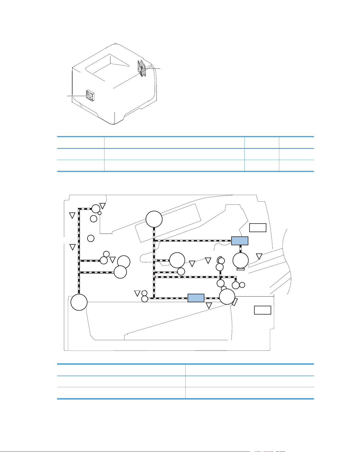
Figure 1-4 Fans
Main fan
Sub fan
Table 1-3 Fans
Description Area cooled Type Speed
Main fan (FM1) Inside the product Intake Full
Sub fan (FM2) Inside the product Intake Full
Figure 1-5 Solenoids and clutches (product)
PS4
PS1
M8001
SW501
PS8001
M8002
PS2
PS502
PS225
SL2
PS215
PS3
SL1
PS205
SW235
Table 1-4 Solenoids and clutches (product)
Item Description
SL1 Tray 1 (multipurpose tray) pickup solenoid
ENWW
SL2 Cassette (Tray 2) pickup solenoid
Engine-control system
9
Page 26
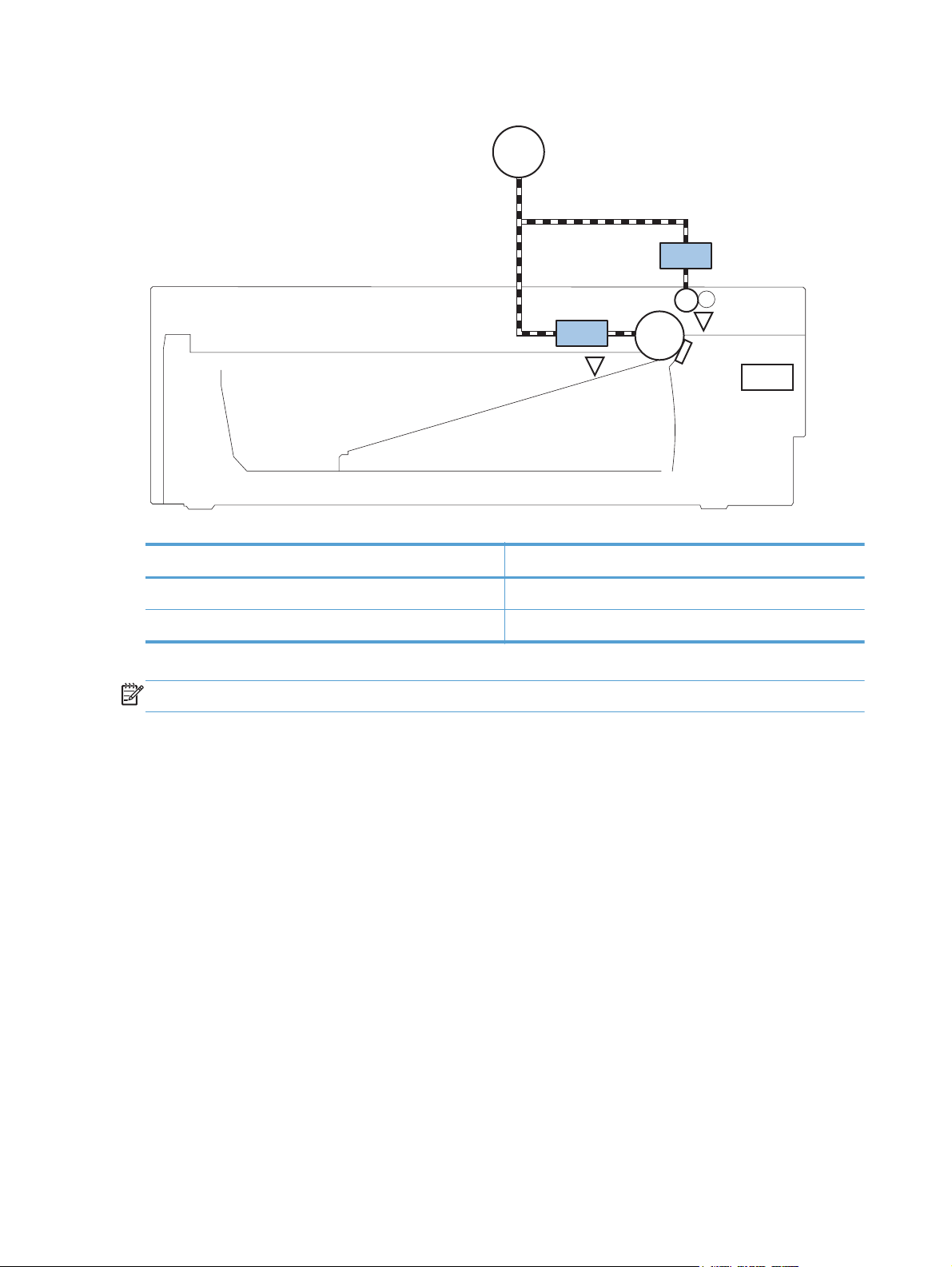
Figure 1-6 Solenoids and clutches (Tray 2 and Tray 3)
M8001
CL1
SL3
PS451
Table 1-5 Solenoids and clutches (Tray 2 and Tray 3)
Item Description
SL3 Paper feeder pickup solenoid
CL1 Paper feeder pickup clutch
NOTE: Tray 2 and Tray 3 are identical 500-sheet input trays.
PS8008
SW461
10 Chapter 1 Theory of operation ENWW
Page 27
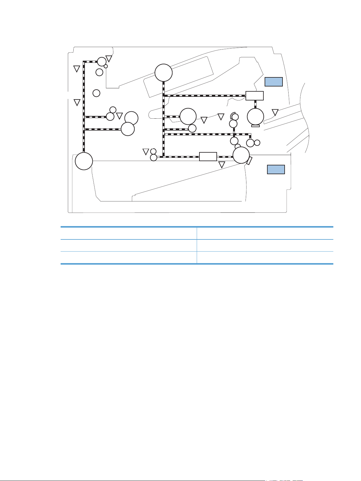
Figure 1-7 Switches (product)
PS4
PS1
M8001
SW501
PS8001
PS2
PS502
M8002
PS225
SL2
PS215
PS3
Table 1-6 Switches (product)
Item Description
SW235 Cassette presence switch
SW501 Cartridge-door switch
SL1
PS205
SW235
ENWW
Engine-control system
11
Page 28
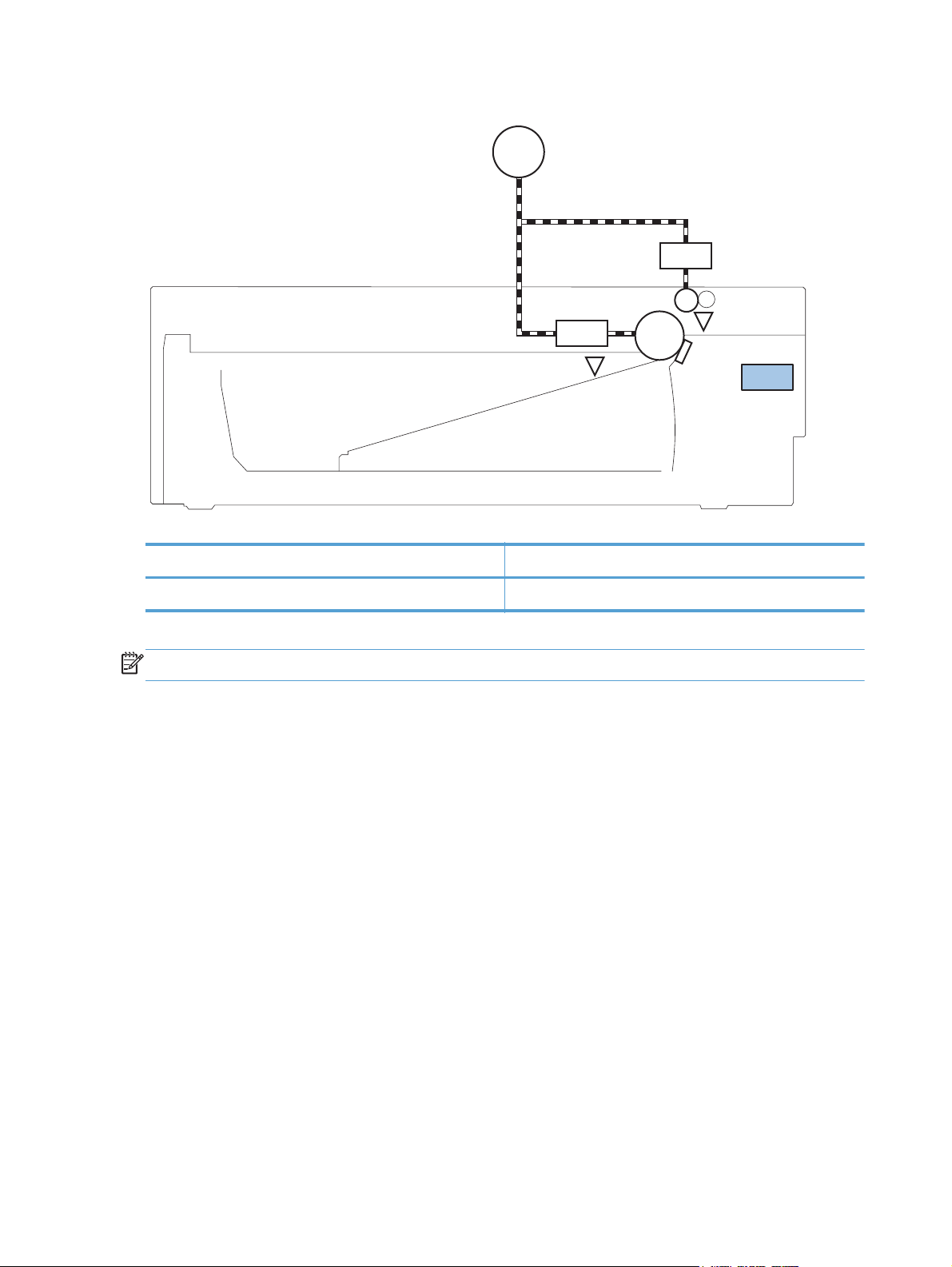
Figure 1-8 Switches (Tray 2 and Tray 3)
M8001
CL1
SL3
PS451
Table 1-7 Switches (Tray 2 and Tray 3)
Item Description
SW461 Paper feeder cassette presence switch
NOTE: Tray 2 and Tray 3 are identical 500-sheet input trays.
PS8008
SW461
12 Chapter 1 Theory of operation ENWW
Page 29
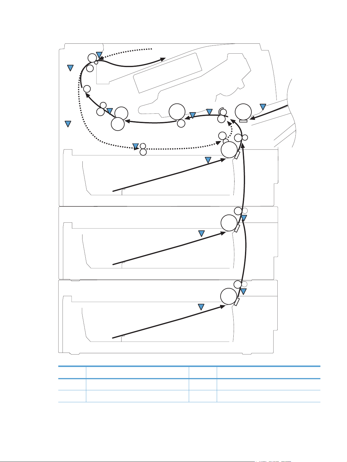
Figure 1-9 Sensors
PS4
PS1
PS8001
PS2
PS502
PS225
PS215
PS205
PS3
PS8008
PS451
ENWW
PS8008
PS451
Table 1-8 Sensors
Item Description Item Description
PS1 Face-up sensor PS225 Paper-width sensor
PS2 Fuser delivery sensor PS502 Duplex paper-feed sensor
Engine-control system
13
Page 30

Table 1-8 Sensors (continued)
Item Description Item Description
PS3 Cassette paper-presence sensor PS451 Paper feeder cassette paper-presence sensor
NOTE: PS451 is used in Tray 3, and Tray 4.
PS4 Face-down tray paper-full sensor PS8001 Rear door sensor
PS205 Tray 1 (multipurpose tray) paper-presence
sensor
PS215 Top-of-Page (TOP) sensor
PS8008 Paper feeder paper-feed sensor
NOTE: PS8008 is used in Tray 2, and Tray 3.
14 Chapter 1 Theory of operation ENWW
Page 31

DC controller operations
The DC controller controls the operational sequences of the product systems.
Figure 1-10 DC controller block diagram
Motor
AC input
Low-voltage
power supply
Fuser
DC controller
Cartridge
Formatter
High-voltage
power supply
Table 1-9 DC controller controlled components
Fan
Solenoid
Photointerrupter
Switch
Accessory
Laser scanner
Component Designator Description
Motor M8001 Main motor
M8002 Fuser motor
Fan FM1 Main fan
FM2 Sub fan
Solenoid SL1 Tray 1 (multipurpose tray) pickup solenoid
SL2 Cassette (Tray 2) pickup solenoid
Photointerrupter PS1 Face-up sensor
PS2 Fuser-delivery sensor
PS3 Cassette paper-presence sensor
PS4 Face-down tray (output bin) paper-full sensor
PS205 Tray 1 (multipurpose tray) presence sensor
PS215 Top-of-Page (TOP) sensor
ENWW
Engine-control system
15
Page 32

Table 1-9 DC controller controlled components (continued)
Component Designator Description
PS225 Paper-width sensor
PS502 Duplex paper-feed sensor
PS8001 Rear-door sensor
Switch SW235 Cassette-presence switch
NOTE: PS8008 is used in Tray 2, and Tray 3
SW240 Power switch
SW260 Interlock switch
SW501 Cartridge-door switch
SW2100 Test-print switch
16 Chapter 1 Theory of operation ENWW
Page 33

Fuser-control circuit
The fuser-control circuit monitors and controls the temperature in the fuser. The product uses on-demand
fusing. The fuser-control circuit consists of the following major components:
Fuser heater (H1): heats the fusing film
●
Thermistor (TH1 and TH2): detects the fuser temperature (contact type)
●
Main thermistor (TH1): controls the temperature in the fuser (contact type)
◦
Sub thermistor (TH2): detects a one-sided temperature rise in the fuser and controls the
◦
temperature in the fuser (contact type)
Thermoswitch (TP1): prevents abnormal temperature rise in the fuser (contact type)
●
Figure 1-11 Fuser control circuit
TP1
H1
Fuser film
TH2
DC controller
TH1
FUSER HEATER CONTROL signal
Fuser heater control
circuit
Engine controller unit
Pressure roller
FUSER TEMPERATURE signal
Fuser heater safety
circuit
Fuser control circuit
ENWW
Engine-control system
17
Page 34

Fuser failure detection
The DC controller determines a fuser unit failure, deactivates the FUSER HEATER CONTROL signal,
releases the relay to interrupt power supply to the fuser heater and notifies the formatter of a failure
state when it encounters the following conditions:
Start-up failure
●
If the main thermistor does not detect a specified temperature during the start-up process of
◦
the heater in the wait period
If the main thermistor does not detect a specified temperature during the heater temperature
◦
control in the initial rotation period
Abnormal low temperature
●
If the main thermistor detects an abnormal low temperature of the fuser unit during the
◦
printing operation
If the sub thermistor detects an abnormal low temperature of the fuser unit during the printing
◦
operation
Abnormal high temperature
●
If the main thermistor detects an abnormal high temperature of the fuser unit
◦
If the sub thermistor detects an abnormal high temperature of the fuser unit
◦
Frequency-detection circuit failure
●
If a specified frequency of the ZERO CROSSING signal is not detected within a specified
◦
period after the product is turned on
18 Chapter 1 Theory of operation ENWW
Page 35

Fuser temperature control
The fuser temperature control maintains the temperature of the fuser heater at its targeted temperature.
The DC controller monitors the FUSER TEMPERATURE (FSRTH1, FSRTH2) signals and sends the FUSER
HEATER CONTROL (FSRD) signal according to the detected temperature. The fuser heater control circuit
controls the fuser heater depending on the signal so that the heater remains at the targeted
temperature.
Figure 1-12 Fuser-heater control circuit
Fuser control circuit
Engine controller unit
DC controller
RL1002
Fuser heater
control circuit
Fuser film
TP1
RL1001
TH2
TH1
Frequency
detection circuit
Relay control
circuit
Fuser heater
safety circuit
ZEROX
RLYD
FSRTH2
FSRTH1
FSRD
ENWW
Fuser
H1
Pressure roller
H1: Fuser heater
TP1: Thermoswitch
TH1: Main thermistor
TH2: Sub thermistor
Engine-control system
19
Page 36

Fuser protective function
The protective function detects an abnormal temperature rise of the fuser unit and interrupts power
supply to the fuser heater.
The following three protective components prevent an abnormal temperature rise of the fuser heater:
DC controller
●
The DC controller interrupts power supply to the fuser heater when it detects an abnormal
◦
temperature of the fuser heater.
Fuser heater safety circuit
●
The fuser heater safety circuit interrupts power supply to the fuser heater when the detected
◦
temperature of the main and sub thermistors is abnormal.
Thermoswitch
●
The contact of the thermoswitch is broken to interrupt power supply to the fuser heater when
◦
the thermoswitch detects an abnormal temperature of the fuser heater.
20 Chapter 1 Theory of operation ENWW
Page 37

Low-voltage power supply
The low-voltage power supply (LVPS) converts ACinput voltage to DCvoltage. The LVPS has two fuses
on the PCA. The LVPS 24 V output is interrupted to the fuser and the high-voltage power supply if the
cartridge-door interlock switch (SW501) is in the off position (cover open).
WARNING! The product power switch only interrupts DC voltage from the LVPS. The AC voltage is
present in the product when the power cable is plugged into a power receptacle and the power switch
is in the off position. You must disconnect the product power cable before servicing the product.
Figure 1-13 Low-voltage power supply (LVPS)
Rectifying
circuit
Fuse (FU1001)
Fuse (FU1002)
+3.3V
generation circuit
+24V
generation circuit
Low-voltage power supply
+3.3V
+24VC
Fuser
control circuit
Fuser
Power switch
control circuit
Power switch
SW240
High-volage
power supply
Main motor
+24VD
Interlock switch
(SW260)
ENWW
Protection
circuit
+5V
generation circuit
DC controller
+3.3VB
+5V
+24VB
Formatter
Engine-control system
21
Page 38

Overcurrent/overvoltage protection
The low-voltage power supply has a protective function against overcurrent and overvoltage to prevent
failures in the power supply circuit. If an overcurrent or overvoltage condition occurs, the system
automatically cuts off the output voltage.
If the DC power is not being supplied from the low-voltage power supply, the protective function might
be running. In such case, turn off the power switch and disconnect the power cable. Do not connect the
power cable or turn on the power switch again until the cause is found.
WARNING! If you believe the overcurrent or overvoltage protection circuits have been activated, do
not connect the product power cable or turn on the product power until the cause of the failure is found
and corrected.
In addition, two fuses in the low-voltage power supply protect against overcurrent. If overcurrent flows
into the AC line, the fuses melt and cut off the power distribution.
For safety reasons, the product interrupts power (24 V) to the main motor and high-voltage power
supply. The interloct switch is turned off to interrupt power when the cartidge door opens (SW260 is
turned off). The AC voltage remains present in the product when the power switch is in the off position.
Disconnect the power cable when disassembling the product.
NOTE: An accidental electrical short while servicing the product can result in a loss of power to the
product causing the control panel to shut down (blank out). Turn the product power off, and then
unplug the power cable. Wait at least 15 minutes before plugging the power cable in and turning the
product power on.
22 Chapter 1 Theory of operation ENWW
Page 39

High-voltage power supply
The high-voltage power supply (HVPS) applies biases to the following components:
Primary charging roller
●
Developing roller
●
Transfer roller
●
Fusing film
●
Figure 1-14 High-voltage power supply
Engine controller unit
DC controller
High-voltage power supply
Fuser film bias
circuit
Primary
charging bias
circuit
FSRB
FILMB
PRI
Fuser
Fuser film
Pressure roller
Cartridge
To primary charging roller
To developing roller
Developing
bias circuit
Transfer bias
circuit
DEV
Photosensitive drum
Transfer roller
TR
ENWW
Engine-control system
23
Page 40

Laser/scanner system
The laser/scanner system receives VIDEO signals from the DCC and the formatter and converts the
signals into latent images on the photosensitive drum.
The main components of the laser/scanner are the laser unit and the scanner motor unit. The DC
controller sends signals to the laser/scanner to control the functions of these components.
Figure 1-15 Laser/scanner system
Engine controller unit
Formatter
DC controller
BDI signal
VIDEO signal
LASER CONTROL signal
SCANNER MOTOR CONTROL signal
Scanning mirror
BD sensor
Scanner motor unit
Photosensitive drum
Laser unit
24 Chapter 1 Theory of operation ENWW
Page 41

Laser failure detection
The DC controller determines an optical unit failure and notifies the formatter, if the laser/scanner
encounters the following conditions:
The scanner motor does not reach a specified rotation within a specified period of the scanner
●
motor start up.
The rotation of the scanner motor is out of specified range for a specified period during the
●
scanner motor drive.
The BD interval is out of a specified value during a print operation.
●
ENWW
Engine-control system
25
Page 42

Image-formation system
Electrophotographic process
The electrophotographic process forms an image on the paper. Following are the major components
used in the process:
Toner cartridge
●
Transfer roller
●
Fuser
●
Laser/scanner
●
The DC controller uses the laser/scanner and HVPS to form the toner image on the photosensitive drum.
The image is transferred to the paper and then fused.
Figure 1-16 Electrophotographic process block diagram
Laser beam
Laser scanner
Fuser
Cartridge
Transfer roller
High-voltage power supply
DC controller
Engine controller unit
26 Chapter 1 Theory of operation ENWW
Page 43

Image formation process
Each of the following processes function independently and must be coordinated with the other product
processes. Image formation consists of the following processes:
Latent-image formation block
●
Step 1: Primary charging
◦
Step 2: Laser-beam exposure
◦
Developing block
●
Step 3: Developing
◦
Transfer block
●
Step 4: Transfer
◦
Step 5: Separation
◦
Fusing block
●
Step 6: Fusing
◦
Drum cleaning block
●
Step 7: Drum cleaning
◦
Figure 1-17 Image formation process
: Media path
: Direction of drum rotation
: Block
: Step
1. Primary charging
Delivery
Drum cleaning
6. Fusing (Fixing)
Fusing (Fixing)
7. Drum cleaning
Latent image formation
2. Laser-beam exposure
5. Separation
Transfer
3. Developing
4. Transfer
Developing
Pickup
ENWW
Image-formation system
27
Page 44

Latent-image formation stage
During the latent-image formation stage, the laser/scanner forms an invisible image on the
photosensitive drum in the toner cartridge.
Primary charging
Step 1: DC and AC biases are applied to the primary charging roller, which transfers a uniform
negative potential to the photosensitive drum.
Figure 1-18 Primary charging
Primary charging roller
Photosensitive drum
Laser beam exposure
Step 2: The laser beam scans the photosensitive drum to neutralize negative charges on parts of the
drum surface. An electrostatic latent image is formed on the drum where negative charges were
neutralized.
Figure 1-19 Laser beam exposure
Primary charging bias
Laser beam
Unexposed area Exposed area
28 Chapter 1 Theory of operation ENWW
Page 45

Developing stage
Toner cartridge
Step 3: In the toner cartridge, the developing cylinder comes in contact with the photosensitive drum to
deposit toner onto the electrostatic latent image.
Figure 1-20 Toner cartridge
Blade
Exposed area Unexposed area
Unexposed area
Toner acquires a negative charge from the friction that occurs when the developing roller rotates
against the developing blade. The developing bias is applied to the developing roller to make a
potential difference between the developing roller and the photosensitive drum. The negatively charged
toner is attracted to the latent image on the photosensitive drum because the drum surface has a higher
potential.
Developing roller
Photosensitive drum
Exposed area
Developing bias
ENWW
Image-formation system
29
Page 46

Transfer stage
Step 4: The transfer charging roller, to which a DC positive bias is applied, imparts a positive charge
on the paper. When the paper comes in contact with the photosensitive drum, the toner is transferred to
the paper.
Figure 1-21 Transfer
Step 5: The elasticity of the paper causes its separation from the photosensitive drum. A static charge
eliminator aids separation by weakening any electrostatic adhesion.
Photosensitive
drum
Media
Transfer roller
Transfer bias
Figure 1-22 Separation
Static charge eliminator
Fusing stage
Step 6: The DC negative bias applied to the fusing film strengthens the holding force of the toner on
the paper and prevents the toner from scattering.
Photosensitive
drum
Media
Transfer roller
30 Chapter 1 Theory of operation ENWW
Page 47

The product uses an on-demand fuser method. The toner image is permanently affixed to the paper with
heat and pressure.
Figure 1-23 Fusing
Cleaning stage
Fuser heater
Brush
Fuser film
Toner
Media
Pressure roller
Fuser bias
Step 7: The cleaning blade scrapes the residual toner off of the photosensitive drum and deposits it
into the waste toner case.
Figure 1-24 Drum cleaning
Cleaning blade
Toner collection box
Photosensitive
drum
ENWW
Image-formation system
31
Page 48

Toner detection
The product uses a nonvolatile memory chip built into the toner cartridge. Toner-cartridge detection
happens when the engine controller detects the presence of a genuine HP toner-cartridge that contains
a memory chip. Toner detection happens as the engine controller reads or writes the data that is stored
on the memory chip. The engine controller renews the information in the prescribed timing and reads or
writes it from or to the memory chip.
The engine controller commands the memory chip to read or write with the following conditions:
Read
●
Power is on
◦
The cartridge door is closed
◦
A command is received from the formatter
◦
Write
●
A page of paper is printed
◦
A command is received from the formatter
◦
When the engine controller fails to read or write three times in a row, it determines that the memory
chip is abnormal and sends a cartridge memory abnormality warning to the formatter.
Figure 1-25 Toner cartridge memory chip
Memory chip
Memory chip
Toner cartridge
32 Chapter 1 Theory of operation ENWW
Page 49

Pickup, feed, and delivery system
The pickup/feed/delivery system consists of several types of feed rollers and sensors. The product uses
a motor and two solenoids to drive the rollers. Three paper-detection sensors detect paper as it passes
through the product. If paper does not reach or pass each sensor within a specified time, the DCC
determines that a jam has occurred and alerts the formatter.
Paper trays
The product has the following paper trays:
Tray 1 (multipurpose tray, all models)
●
Tray 2 (500-sheet tray, all models)
●
Tray 3 (optional 500-sheet input tray)
●
ENWW
Pickup, feed, and delivery system
33
Page 50

Photo sensors and switches
Figure 1-26 Photo sensors and switches (product)
PS4
PS1
M8001
SW501
PS8001
M8002
PS2
PS502
PS225
SL2
PS215
PS3
SL1
PS205
Table 1-10 Photo sensors and switches (product)
Item Description Item Description
PS1 Face-up sensor PS215 Top-of-Page (TOP) sensor
PS2 Fuser-delivery sensor PS225 Paper-width sensor
PS3 Cassette paper-presence sensor PS502 Duplex paper-feed sensor
SW235
PS4 Face-down tray paper-full sensor PS8001 Rear-door sensor
PS205 Tray 1 (MP tray) paper-presence sensor SW235 Cassette-presence sensor
34 Chapter 1 Theory of operation ENWW
Page 51

Figure 1-27 Photo sensors and switches (Tray 2 and Tray 3)
M8001
CL1
SL3
PS451
Table 1-11 Photo sensors and switches (Tray 2 and Tray 3)
Item Description
PS451 Paper feeder cassette-paper presence sensor
PS8008 Paper feeder paper-feed sensor
SW461 Paper feeder cassette-presence switch
PS8008
NOTE: Tray 2 and Tray 3 are identical 500-sheet input trays.
SW461
ENWW
Pickup, feed, and delivery system
35
Page 52

Solenoids and clutches
Figure 1-28 Solenoids and clutches (product)
PS4
PS1
M8001
SW501
PS8001
M8002
PS2
PS502
PS225
SL2
PS215
PS3
SL1
PS205
SW235
Table 1-12 Solenoids and clutches (product)
Item Description
SL1 Tray 1 (multipurpose tray) pickup solenoid
SL2 Cassette (Tray 2) pickup solenoid
36 Chapter 1 Theory of operation ENWW
Page 53

Figure 1-29 Solenoids and clutches (Tray 2 and Tray 3)
M8001
CL1
SL3
PS451
Table 1-13 Solenoids and clutches (Tray 2 and Tray 3)
Item Description
SL3 Paper feeder pickup solenoid
CL1 Paper feeder pickup clutch
NOTE: Tray 2 and Tray 3 are identical 500-sheet input trays.
PS8008
SW461
ENWW
Pickup, feed, and delivery system
37
Page 54

Tray 1 or Tray 2
Pickup and feed unit
The pickup and feed unit uses the following components and processes.
Cassette paper size detection/cassette paper detection
NOTE: To find the following components, see Photo sensors and switches on page 34.
PS3: cassette paper-presence sensor
●
PS225: paper width sensor (detects paper width after the paper enters the paper path)
●
Cassette pickup
NOTE: To find the following components, see Solenoids and clutches on page 36.
SL2: cassette (Tray 2) pickup solenoid
●
Tray 1 paper pickup
NOTE: To find the following components, see Photo sensors and switches on page 34 and Solenoids
and clutches on page 36.
PS205: Tray 1 (multipurpose tray) paper-presence sensor
●
SL1: Tray 1 (multipurpose tray) pickup solenoid
●
38 Chapter 1 Theory of operation ENWW
Page 55

Paper pickup and feed
The following figure shows the pickup and feed paper path.
NOTE: Duplex models include a duplex paper-feed path for automatic two-sided printing.
Figure 1-30 Pickup, feed, and delivery block diagram
Delivery roller
Fuser film
Pressure roller
Simplex paper path
Duplex paper path
Photosensitive drum
Transfer roller
Cassette pickup roller
MP tray pickup roller
MP tray separation pad
Cassette separation pad
ENWW
Tray 1 or Tray 2
39
Page 56

Jam detection
The product uses the following sensors to detect the presence of paper and to check for jams. If paper
does not reach or pass each sensor within a specified time, the engine control unit (ECU) determines
that a jam has occurred and alerts the formatter.
NOTE: To find the following components, see Photo sensors and switches on page 34.
Table 1-14 Sensors
Paper Jam Sensors PS2 Fuser-delivery sensor
Paper present sensors PS4 Face-down tray paper-full sensor
PS215 Top-of-Page (TOP) sensor
PS502 Duplex paper-feed sensor
PS225 Paper width sensor
PS8008 Paper feeder paper-feed sensor
NOTE: PS8008 is used in Tray 2 and
Tray 3.
The product detects the following jams:
Pickup delay jam
●
Pickup stationary jam
●
Delivery delay jam
●
Delivery stationary jam
●
Fuser wrapping jam
●
Door open jam
●
Residual paper jam
●
Duplex re-pickup jam
●
40 Chapter 1 Theory of operation ENWW
Page 57

Additional tray
NOTE: This product supports identical 500-sheet input trays (Tray 2 and Tray 3).
Tray driver PCA
The following figure shows the signals between the DC controller and the tray driver PCA.
Figure 1-31 Tray 2 and Tray 3 driver PCA block diagram
Optional paper feeder
Clutch
DC controller
+24V
Paper feeder
Solenoid
connector PCB
Photointerrupter
Switch
ENWW
Additional tray
41
Page 58

Paper pickup and feed
NOTE: Tray 2 and Tray 3 are identical 500-sheet input trays.
The following figure shows the pickup and feed paper path (Tray 3 shown).
Figure 1-32 Tray 2 and Tray 3 pickup, feed, and delivery block diagram
Optional paper feeder
separation pad
Optional paper feeder
pickup roller
Optional paper feeder
feed roller
42 Chapter 1 Theory of operation ENWW
Page 59

Paper level and size detection
PS451: paper feeder paper-presence sensor detects if paper is present in the tray.
●
NOTE: PS451 is used in Tray 2 and Tray 3.
Paper size is detected after the page enters the product. See
●
cassette paper detection on page 38.
Jam detection
PS8008: paper feeder paper-feed sensor detects jams in the paper feeder.
●
Cassette paper size detection/
ENWW
Additional tray
43
Page 60

Scanner system
The flatbed image scanner captures an electronic image of the document on the glass. The scanner
does this by illuminating the document with LEDs (red, green, and blue) and capturing the image in the
image sensor to create an electronic format of the document. The flatbed scanner consists of three main
elements.
CIS scanner. The CIS (contact image sensor) scanner captures an image using the product's
●
optical path. Red, green, and blue LEDs sequentially illuminate a small strip of the document
(called a raster line), and the optical system captures each color in a single row of CCD sensors
that cover the entire page width. Because only one color is captured for each line per exposure,
the three colors are recombined electronically to create the full-color image. For monochromatic
scans or copies, all three LEDs are illuminated to create a white light for the scan so the raster line
can be captured in one exposure.
Mechanical carriage drive. The carriage drive moves the CIS scan head along the document
●
length to create the image. In this product, a small DC motor with an optical encoder creates this
motion. The speed of the carriage drive is proportional to the scan resolution (300 ppi is much
faster than 1200 ppi) and also proportional to the type of scan (color scans are three-times slower
than monochromatic scans). A 1200 ppi color scan moves so slowly that the product might
appear to not be working, whereas a monochromatic copy scan moves at 50 times that speed
and will be a little noisy.
Image processing system (formatter). The formatter processes the scanner data into either
●
a copy or a scan to the computer. For copies, the image data is sent directly to the product
without being transmitted to the computer. Depending on user selections for the copy settings, the
formatter enhances the scanner data significantly before sending it to the product. Image data is
captured at 300 ppi for copies and is user selectable for scans to the computer. Each pixel is
represented by 8 bits for each of the three colors (256 levels for each color), for a total of 24 bits
per pixel (24-bit color).
Scanner power-on sequence of events
When the product is turned on, it performs the following tests:
Motor test. The product moves the motor left and right to confirm operation. It reports a scanner
●
error 12 if no motion is detected in the motor encoder system.
Wall find. The scan carriage moves slowly to the left while monitoring an encoder on the
●
carriage motor to determine when the carriage has found the side wall or stop. This enables the
product to identify the document origin (position of the original). If the document origin cannot be
located, a default position is used instead.
LED check. The product moves the carriage to the white calibration label under the left side of
●
the flatbed image scanner, and it verifies that the minimum and maximum response is acceptable.
It reports a scanner error 14 if the response is unacceptable.
Home find. The scan carriage uses the optical scanner to find physical reference features that
●
relate to the document origin at the left side of the image glass. This process ensures accurate
location of the first document pixels so that the user documents will have an accurate placement of
44 Chapter 1 Theory of operation ENWW
Page 61

the image on scans and copies. It reports a scanner error 6 message if the reference features are
not found.
Calibration. This test, also known as scanner color calibration, enables the product to identify
●
the black and white on every pixel in the CCD. Calibration occurs in two major processes: a
broad (analog) adjustment of all pixels to bring them into the target output range, and a pixel-bypixel adjustment (digital) to fine tune the actual black and white response. The calibration process
occurs under the left side of flatbed image scanner where there is a special white calibration
label.
Calibration is the most important step in creating a high quality image. Calibration problems can
include color inaccuracies, brightness inaccuracies, and vertical streaks through the image. The
calibration process identifies any bad pixels and enables the image formatter to recreate the lost
information from adjacent pixels. Extreme cases of this problem can appear as large vertical
streaks or image smears. The user has no control over the calibration process itself or this pixelreplacement process.
Copy or scan sequence of events
To create an accurate rendition of a document, the scanner must be calibrated for the requested
operation. If the user selects a scan at 600 ppi color, the flatbed image scanner calibrates for that
specific operational mode. Subsequently, the flatbed image scanner automatically re-calibrates for the
next requested operation. Calibration does not occur for every new copy request.
Normal sequence of operation for a flatbed copy or scan job includes the following.
1. LEDs illuminate.
2. Carriage motion begins moving the CIS scanner toward the right.
3. Image capture continues for the entire page or length requested in a scan operation.
4. Carriage returns to the home position on the left.
ENWW
Scanner system
45
Page 62

46 Chapter 1 Theory of operation ENWW
Page 63

2 Solve problems
NOTE: To perform diagnostic and configuration procedures (for example, resetting page counts) for
the product, you must install the CP1210 Service Config Tool (available at your HP authorized repair
center).
Solve problems checklist
●
Menu map
●
Troubleshooting process
●
Tools for troubleshooting
●
Clear jams
●
Paper feeds incorrectly or becomes jammed
●
Solve image-quality problems
●
Clean the product
●
Solve performance problems
●
Solve connectivity problems
●
Service mode functions
●
Solve fax problems
●
Product updates
●
ENWW 47
Page 64

Solve problems checklist
1. Ensure that the product is set up correctly.
a. Press the power button to turn on the product or to deactivate the Auto-Off mode.
b. Check the power-cable connections.
c. Ensure that the line voltage is correct for the product power configuration. (See the label on
the back of the product for voltage requirements.) If you are using a power strip and its
voltage is not within specifications, plug the product directly into the wall. If it is already
plugged into the wall, try a different outlet.
2. Check the cable connections.
a. Check the cable connection between the product and the computer. Ensure that the
connection is secure.
b. Ensure that the cable itself is not faulty by using a different cable if possible.
c. Check the network connection. Ensure the network light is lit. The network light is next to the
network port on the back of the product.
If the product remains unable to connect to the network, uninstall and then reinstall the
product. If the error persists, contact a network administrator.
3. Check to see if any messages appear on the control panel.
4. Ensure that the paper you are using meets specifications.
5. Ensure that the paper is loaded correctly in the input tray.
6. Ensure that the product software is installed correctly.
7. Verify that you have installed the printer driver for this product, and that you are selecting this
product from the list of available printers.
8. Print a configuration page.
a. If the page does not print, verify that the input tray contains paper and that the paper is
properly loaded.
b. Ensure that the toner cartridge is installed correctly.
48 Chapter 2 Solve problems ENWW
Page 65

c. If the paper jams in the product, clear the jam.
d. If the print quality is unacceptable, complete the following steps:
Verify that the print settings are correct for the paper you are using.
●
Solve the print-quality problems.
●
9. Print a small document from a different program that has printed in the past. If this solution works,
then the problem is with the program you are using. If this solution does not work (the document
does not print), complete these steps:
a. Try printing the job from another computer that has the product software installed.
b. Check the cable connection. Direct the product to the correct port, or reinstall the software,
selecting the connection type you are using.
ENWW
Solve problems checklist
49
Page 66

Menu map
Use the following procedure to print a control panel menu layout map.
1.
From the Home screen, touch the Setup
2. Touch the Reports button.
3. Touch the Menu Structure button.
button.
50 Chapter 2 Solve problems ENWW
Page 67

Troubleshooting process
When the product malfunctions or encounters an unexpected situation, the product control panel alerts
you to the situation. This chapter contains information to help diagnose and solve problems.
Use the pre-troubleshooting checklist to evaluate the source of the problem and to reduce the
●
number of steps that are required to fix the problem.
Use the troubleshooting flowchart to pinpoint the root cause of hardware malfunctions. The
●
flowchart guides you to the section of this chapter that contains steps for correcting the
malfunction.
Before beginning any troubleshooting procedure, check the following issues:
Are supply items within their rated life?
●
Does the configuration page reveal any configuration errors?
●
NOTE: The customer is responsible for checking supplies and for using supplies that are in good
condition.
Pre-troubleshooting checklist
The following table includes basic questions to ask the customer to quickly help define the problem(s).
General topic Questions
Environment
Paper
Input trays
Is the product installed on a solid, level surface (± 1°)?
●
Is the power-supply voltage within ± 10 volts of the specified power source?
●
Is the power-supply plug inserted in the product and the outlet?
●
Is the operating environment within the specified parameters?
●
Is the product exposed to ammonia gas, such as that produced by diazo
●
copiers or office cleaning materials?
NOTE: Diazo copiers produce ammonia gas as part of the copying
processes. Ammonia gas (from cleaning supplies or a diazo copier) can have
an adverse effect on some product components (for example, the toner
cartridge OPC).
Is the product exposed to direct sunlight?
●
Does the customer use only supported paper?
●
Is the paper in good condition (no curls, folds, or distortion)?
●
Is the paper stored correctly and within environmental limits?
●
Is the amount of paper in the tray within specifications?
●
Is the paper correctly placed in the tray?
●
ENWW
Are the paper guides aligned with the stack?
●
Is the tray correctly installed in the product?
●
Troubleshooting process
51
Page 68

General topic Questions
Toner cartridge
Transfer unit and fuser
Covers
Condensation
Miscellaneous
●
●
●
●
●
●
●
●
Determine the problem source
When the product malfunctions or encounters an unexpected situation, the product control panel alerts
you to the situation. The troubleshooting flowchart helps you diagnose the root cause of the problem.
The remainder of this chapter provides steps for correcting problems.
Is the toner cartridge installed correctly?
Are the transfer unit and fuser installed correctly?
Is the front cover closed?
Does condensation occur following a temperature change (particularly in
winter following cold storage)? If so, wipe affected parts dry or leave the
product on for 10 to 20 minutes.
Was a toner cartridge opened soon after being moved from a cold to a warm
room? If so, allow the toner cartridge to sit at room temperature for 1 to 2
hours.
Check for and remove any non-HP components (toner cartridges, memory
modules, and EIO cards) from the product.
Remove the product from the network to ensure that the failure is associated
with the product before beginning troubleshooting.
For any print-quality issues, calibrate the product.
Troubleshooting flowchart
This flowchart highlights the general processes that you can follow to quickly isolate and solve product
hardware problems.
Each row depicts a major troubleshooting step. A “yes” answer to a question allows you to proceed to
the next major step. A “no” answer indicates that more testing is needed. Go to the appropriate section
in this chapter, and follow the instructions there. After completing the instructions, go to the next major
step in this troubleshooting flowchart.
Table 2-1 Troubleshooting flowchart
1
Power on
2
Control panel
messages
Is the product on and does a readable
message display?
Yes
Does the message Ready display on the
control panel?
Yes
No
No
Follow the power-on troubleshooting checks. See Power subsystem
on page 53.
After the control panel display is functional, see step 2.
1. Follow the control panel message to resolve the problem.
Touch the
2. If more information is required to troubleshoot the problem,
refer to the troubleshooting section of the product user guide.
After the errors have been corrected, go to step 3.
button to get more information.
52 Chapter 2 Solve problems ENWW
Page 69

Table 2-1 Troubleshooting flowchart (continued)
3
Event log
4
Information
pages
5
Image quality
6
Interface
Open the Troubleshooting menu and print an
event log to see the history of errors with this
product.
Does the event log print?
Yes
Open the Reports menu and print the
configuration pages to verify that all the
accessories are installed.
Are all the accessories installed?
Yes
Does the print quality meet the customer's
requirements?
Yes
Can the customer print successfully from the
host computer?
Yes. This is the end of
the troubleshooting
process.
No
No
No
No
If the event log does not print, check for error messages.
If paper jams inside the product, see the jams section of the
product service manual.
If error messages display on the control panel when you try to print
an event log, see the control panel message section of the service
manual.
After successfully printing and evaluating the event log, see step 4.
If accessories that are installed are not listed on the configuration
page, remove the accessory and reinstall it.
After evaluating the configuration pages, see step 5.
Compare the images with the sample defects in the image defect
tables. See the images defects table in the product service manual.
After the print quality is acceptable, see step 6.
Verify that all I/O cables are connected correctly and that a valid
IP address is listed on the Jetdirect configuration page.
If error messages display on the control panel when you try to print
an event log, see the control panel message section of the service
manual.
Power subsystem
Power-on checks
The basic product functions should start up when the product is connected into an electrical outlet and
the power switch is pushed to the on position. If the product does not start, use the information in this
section to isolate and solve the problem.
Power-on troubleshooting overview
Turn on the product power. If the control panel display remains blank, random patterns display, or
asterisks remain on the control panel display, perform power-on checks to find the cause of the
problem.
During normal operation, the main cooling fan begins to spin briefly after the product power is turned
on. Place your hand over the holes in the right-side cover, near the formatter. If the fan is operating,
you will feel air passing out of the product. You can also lean close to the product and hear the fan
operating. Place your hand over the hole in the right-front lower corner. If the fan is operating, you
should feel air being drawn into the product. When this fan is operational, the DC side of the power
supply is functioning correctly.
When the customer can print from the host computer, this is the
end of the troubleshooting process.
ENWW
Troubleshooting process
53
Page 70

After the fan is operating, the main motor turns on (unless the right or front cover is open, a jam
condition is sensed, or the paper-path sensors are damaged). You might be able to visually and
audibly determine if the main motor is turned on.
If the fan and main motor are operating correctly, the next troubleshooting step is to isolate print
engine, formatter, and control panel problems. Perform an engine test and if the formatter is damaged,
it might interfere with the engine test. If the engine-test page does not print, try removing the formatter
and then performing the engine test again. If the engine test is then successful, the problem is almost
certainly with the formatter, the control panel, or the cable that connects them.
If the control panel is blank when you turn on the product, check the following items.
1. Make sure that the product is connected directly into an active electrical outlet (not a power strip)
that delivers the correct voltage.
2. Make sure that the power switch is in the on position.
3. Make sure that the fan runs briefly, which indicates that the power supply is operational.
4. Make sure that the control panel display wire harness is connected.
5. Make sure that the formatter is seated and operating correctly. Turn off the product and remove
the formatter. Reinstall the formatter, and then verify that the formatter LED is blinking.
6. Remove any external solutions, and then try to turn the product on again.
NOTE: If the control panel display is blank, but the main cooling fan runs briefly after the product
power is turned on, try printing an engine-test page to determine whether the problem is with the
control-panel display, formatter, or other product assemblies.
Control-panel checks
Use the product control panel to conduct tests on the control panel LEDs, display, or buttons.
NOTE: When the menus are accessed, some of the touchscreen buttons located along the sides of the
control-panel display are not illuminated. Use the figure below to locate the Cancel
left arrow button to access the control-panel tests.
button and the
54 Chapter 2 Solve problems ENWW
Page 71

Figure 2-1 Control-panel 2ndary Service test access buttons
Table 2-2 Control-panel 2ndary Service test access buttons
Item Description
1 Left arrow button
2
1.
From the Home screen on the product control panel, touch the Setup
2. Touch the left arrow button, and then quickly touch the Cancel
Cancel
button
button.
button. The display should return
to Ready status.
3.
Press the Setup
button again to open the menus. The first menu should be the 2ndary Service
menu.
4. Touch the 2ndary Service menu, and then scroll to one of the following menu items.
LED Test
●
Display Test
●
Button Test
●
5. Touch the menu item to begin the test.
6. After completing the test, return the product to the Ready state, and then touch the Cancel
button to remove the 2ndary Service menu from the menu list.
ENWW
Troubleshooting process
55
Page 72

Tools for troubleshooting
The section describes the tools that can help you solve problems with your product.
Diagrams
Block diagrams
Figure 2-2 Product cross section
1
2
4
3
5
6
7
16
17
Item Description Item Description
1 Face-down delivery roller 10 Cassette (Tray 2) separation pad
2 Fuser film 11 Cassette (Tray 2) pickup roller
3 Laser/scanner 12 Duplex repickup roller
15
14
13
12
11
10
8
9
56 Chapter 2 Solve problems ENWW
Page 73

Item Description Item Description
4 Photosensitive drum 13 Registration roller
5 Toner cartridge 14 Transfer roller
6 Registration shutter 15 Duplex-feed roller (duplex models)
7 Tray 1 (multipurpose tray) pickup roller 16 Pressure roller
8 Tray 1 (multipurpose tray) separation pad 17 Fuser output roller
9 Feed roller
Figure 2-3 Optional paper feeder (Tray 2 and Tray 3) cross section
2
1
ENWW
Item Description
1 Pickup roller
2 Feed roller
3 Separation pad
3
Tools for troubleshooting
57
Page 74

Location of connectors
DC controller connections
Figure 2-4 DC controller connections
J2400
J2103J2104 J2102
J2704
J2703
J2311
J2301
J2302
J2310
J2306
J2105
J2307
J2304
J2702
FT1
FT2
J2308 J2401 J2303
J2100
J2201
J2701
J2700
J2200
Item Description Item Description Item Description
J2100 J2302 J2400
J2102 J2303 J2401
J2103 J2304 J2700
J2104 J2306 J2701
J2105 J2307 J2702
J2200 J2308 J2703
J2201 J2310 J2704
J2301 J2311
58 Chapter 2 Solve problems ENWW
Page 75

Formatter connections
TAZ
Figure 2-5 Formatter connections
J18 WI FI
J17 THUMB
J19
J21 ADF SCAN
SCANNER
J20
J3
J27
POWER
J7
J24 SNAPPER FAX
J22 ADF MOTOR
J8 LAN
J16 USB DEVICE
Item Description Item Description
J3 Control panel J19 Flatbed scanner
ENWW
J7 Power J20 Flatbed motor
J8 LAN J21 ADF/Scanner
J16 USB Device J22 ADF motor
J17 USB J24 Snapper Fax
J18 Wifi J27 ICB
Tools for troubleshooting
59
Page 76

Plug and port locations
1
2
3
4
5
1 Kensington lock
2 Local area network (LAN) Ethernet (RJ-45) network port
3 Hi-Speed USB 2.0 printing port
4 Fax port (to telephone)
5 Fax port (to line)
60 Chapter 2 Solve problems ENWW
Page 77

Locations of major assemblies
Figure 2-6 External assembly locations
13
12
1
2
8
7
6
11
10
9
Item Description Item Description
1 Dummy cover 8 I/O plate
2 Formatter cover 9 Power switch
3Right cover 10Tray 2
4 Left cover 11 Tray 1/Cartridge drawer door
3
5
4
5 Rear door 12 Output-bin extension for long paper
6 Power port 13 Standard output bin
7Right-rear cover
ENWW
Tools for troubleshooting
61
Page 78

Figure 2-7 Major assembly locations
1
32
5
Item Description
1 Fuser
2 Laser/scanner
3 Registration assembly
4 Pickup assembly
5 Duplex paper-feed assembly
4
62 Chapter 2 Solve problems ENWW
Page 79

Figure 2-8 Motors, fans, solenoids, and rollers assembly locations
Item Description Item Description
1 Fuser motor 6 Main fan
2 Tray 1 (multipurpose tray) pickup roller 7 Cassette (Tray 2) separartion pad
3 Tray 1 (multipurpose tray) pickup solenoid 8 Cassette (Tray 2) pickup solenoid
4 Transfer roller 9 Cassette (Tray 2) pickup roller
5 Tray 1 (multipurpose tray) separation pad 10 Sub fan
ENWW
Tools for troubleshooting
63
Page 80

Figure 2-9 PCA assembly locations (1 of 2)
Item Description
1 High-voltage power supply
2 Formatter
Figure 2-10 PCA assembly locations (2 of 2)
1
Item Description
2
1 DC controller PCA
2 Low-voltage power supply
64 Chapter 2 Solve problems ENWW
Page 81

General timing charts
Power ON
Figure 2-11 General timing chart
15 Main fan (FM1)
16 Sub fan (FM2)
232122
19
20
17
18
14 Fuser film bias
12 Developing bias
13 Transfer bias
11 Primary charging bias
10 Fuser heater
8 Main motor (M8003)
9 Fuser motor (M8002)
7 Scanner motor (M3)
3 TOP sensor (PS215)
4 Fuser output sensor(PS2)
5 /BD signal
6 VIDEO signal
1 Print start command (EEC12)
2 Cassette pickup solenoid (SL2)
LSTR STBYWAIT STBY INTR PRINT
ENWW
Tools for troubleshooting
65
Page 82

Circuit diagrams
Figure 2-12 General circuit diagram (1 of 2)
78
Fuser unit
21
J15B
21
J15A
12
TP1
12
TP
TB2
TB1
23451
J1002
Low-voltage
power supply
J1303
J1304
J1313
J1311
GND
GND
GND
+24VB
+3.3VB
J4209
J1302
J1301
+3.3VB
H1
J1011
J1404
GND
INL1001
J1403
J1402
GND
+5VA
81234567 910
AC-H
AC-N
J1001
J1401
+5VA
+3.3VA
17161514131211
Formatter
J1701
WAKE ENG
3
WAKE VC
412
GND
1
CNT0
13
123456
RLTEST
RLGND
J1803
5
6
789
SDA
SCL
/CCRT
Laser scanner unit
Laser driver
J100
13
J100
4
5
2
3
7
6
GND
VDO1
/VDO1
GND
CNT2
CNT1
101112
9
13
J1811
J9999
GND
+3.3VA
IOTTXD
IOTRXD
1234567
J1812
17
1011121314
GND
SC
SCLK
/BDO
10
/VDO1
987653214
J4205
17
J4205
9
8
12
13
10
11
LPWM
+5V
GND
VDO2
/VDO2
/BDI
412
35678
J1702
J1801
23
J1801
J1314
J1312
23
J1800
151617
J1800
/VDO2
VDO2
GND
VDO1
GND
23
22
21
20
19
18
17
16
15
14
13
12
11
10
9
8
7
6
5
4
3
2
1
23
22
21
20
19
18
17
16
15
14
13
12
11
10
9
8
7
6
5
4
3
2
1
SDA
WAKE ENG
WAKE VC
CNT1
CNT0
CNT2
/BDI
LPWM
SCL
/CCRT
SCLK
SC
/BDO
GND
IOTTXD
IOTRXD
CURRMS
CURLIM
FSRD
FSRMSK
RLYD34
RLYD1
/RLOFF1
GND
+24VC
+24VD
GND
/RLOFF3
SIN
SQUARE
ZEROX
/RLOFF2
VLIM
CH VOLT
CH_VOLTOFF
GND
GND
+3.3VC
+3.3VC
GND
+3.3VB
GND
+3.3VA
3.3VBOFF
3.3VCOFF
/24VAOFF
/24VBOFF
/24VCOFF
65
23
22
21
20
19
18
17
16
15
14
13
12
11
10
9
8
7
6
5
4
3
2
1
23
22
21
20
19
18
17
16
15
14
13
12
11
10
9
8
7
6
5
4
3
2
1
J2701
J2700
21
SW260
J260
Interlock
switch
23
J2306
3.3VB
FDOOR SNS
21
CST
media
out sensor
PS3
J6
CSTPSNS
J2301
Memory
tag
MPT media
J1703
321
TAGOUT
+3.3VC
GND
TAGIN
12
123
J2401
J2701
21
J2702
23
J2700
J2307
12
J2703
+24VC
/TRAYSNS
GND
J230
Cassette
detection
switch
SW235
12
FT1 FT2
SW501
32
Cartridge door switch
+24VD
J2704
J2303
123456
+3.3VC
J3
Face-up
sensor
PS1
GND
/FUSNS
123
J4
PS4
Face-down output
bin media-full sensor
PS205
out sensor
J200
/MPPSNS
321
J2302
GND
+3.3VC
321
GND
+3.3VC
FULLSNS
J8007DA
J8007LA
PF media
presence sensor
PS451
21
SW461
PF cassette
presence switch
Paper feeder
+3.3V
GND
SL
SL3
PF pickup solenoid
/OPFTRAYS1
GND
PSNS1
+24U
SL1
321
21
21
J405
J407
J406
J451
J461
66 Chapter 2 Solve problems ENWW
Page 83

Figure 2-13 General circuit diagram (2 of 2)
43 2 1
Fuser unit
Fuser output sensor
CST
pickup
solenoid
SL2 SL1
MPT
pickup
solenoid
PS2
123
J2
J24H
321
J24
123
J22
SLSL
TH2
TH1
21
345612
123456
12
Fuser motor
J19
J18H
J18
J8002
M8002
M
87654321
Main motor
J8003
M8003
Laser scanner unit
Scanner
motor
J8001
M3
M
J12
4321
F
Sub fan
FM2
Rear
door
sensor
123
M
J8010L
7654321
J8010DH
J8010D
321
PS8001
321
123
J2310
J2201
OPF_SL2
J401
CSTSL
+24VC
21
/OPF_TRAYS2
/OPF_PSNS2
101112
Paper feeder
MPSL
+24VC
12
J2311
DC Controller
OPF_PFEDS1
OPF_SL1
/OPF_PSNS1
/OPF_TRAYS1
OPF_PFEDS2
+3.3VC
5
6
412
789
12
12
J8007LA
9
4
8765321
716543289101112
connector
J402
+3.3VL
J280
PF media
feed sensor
J8008
123
PF feed
clutch
+24VC
CL
J2102
PS8008
CL1
GND
FSRTH2
GND
FSROUTSNS
98 2345617
J2400
121110982345617
OPF_CL
GND
+24VC
3
J8007D
J8007L
12
11
10
+3.3VC
J404
J403
87654321
+3.3VB
3
21
2
1
GND
J2304
Environment
PFEDS1
+3.3V
+24U
FSRTH1
12
ENVTEMP
sensor
TH3
GND
CL1
GND
J2308
123
FAN1ON
FM1
Main fan
FAN1LCK
321
GND
12345678
J2103
J2105
+3.3VA
GND
Power
switch
SW240
12
LED240
21
/FM_DEC
/FM_ACC
FM_FG
FM_REV
GND
+24VC
+24VD
+24VD
321
POWER SW
LED DRIVE
MM_FG
J290
/MM_ACC
/MM_DEC
GND
GND
1234567
FAN2LCK
GND
10 9 8 2345617
FAN2ON
/RDOORSNS
GND
+3.3VC
Test print switch
SW2100
12
J2200
GND
/SCMACC
/SCMDEC
J2104
+24VC
27
/TOPSNS
/DEVACPWM
DEVACCLK
TONS2
J501
27
J501
TB506 TB507
TR FSRB
TB509 TB510
J507
321
/TOPSNS
+3.3V
GND
J210
TOP sensor
J1610
PWSNS
16151413121110
TONS1
TRFCS
GND(+3.3V)
High-voltage
power supply
213456789101112131415161718192021222324252627
TRFCLK
FSRCLK
PRIDCPWM
/FSRPWM
/PRIDCCLK
TB505
DEV
TB508
FILMB PA1 PA2
J513
123
GND
PWSNS
+3.3V
J220
Paper width
sensor
/PRIACPWM
PRIACCLK
987654321
DEVDCPWM
/DUPSNS
/TRFNCLK
Duplex
feed sensor
PS502
TRFPWM
J9997
+3.3VC
GND(+3.3V)
J107
FT4
+3.3VC
TONER
12
MD2
21
J2100
GND(+24D)
GND(+24D)
MD0
+24VD
J502
FT3
+24VD
E
D
+24VD
2726252423222119201718
C
PRI
B
ENWW
J8009DA
PS225
/OPF_TRAYS2
OPF_SL2
12
10
11
987
12
+3.3V
GND
OPF_PFEDS2
OPF_PSNS2
65321
4
+24V
OPF_CL
J8009D
PS215
Tools for troubleshooting
A
67
Page 84

Use HP Device Toolbox (Windows)
Use the HP Device Toolbox for Windows to view or change product settings from your computer.
This tool opens the HP Embedded Web Server for the product.
NOTE: This tool is available only if you performed a full installation when you installed the product.
The HP Embedded Web Server, however, is still available by opening a Web browser and entering the
product IP address in the browser address box.
1. Click the Start button, and then click the Programs item.
2. Click your HP product group, and then click the HP Device Toolbox item.
Tab or section Description
Home tab
Provides product, status, and
configuration information.
System tab
Provides the ability to configure the
product from your computer.
Device Status: Shows the product status and shows the approximate percent life
●
remaining of HP supplies.
Supplies Status: Shows the approximate percent life remaining of HP supplies.
●
Actual supply life remaining can vary. Consider having a replacement supply
available to install when print quality is no longer acceptable. The supply does not
need to be replaced unless the print quality is no longer acceptable.
Device Configuration: Shows the information found on the product configuration
●
page.
Network Summary: Shows the information found on the product network
●
configuration page.
Reports: Allows you to print the configuration and supplies status pages that the
●
product generates.
Event Log: Shows a list of all product events and errors.
●
Device Information: Provides basic product and company information.
●
Paper Setup: Allows you to change the paper-handling defaults for the product.
●
Print Quality: Allows you to change the print quality defaults for the product,
●
including calibration settings.
Paper Types: Allows you to configure print modes that correspond to the paper
●
types that the product accepts.
System Setup: Allows you to change the system defaults for the product.
●
Service: Allows you to start the cleaning procedure on the product.
●
Product Security: Allows you to set or change the product password.
●
Save and Restore: Save the current settings for the product to a file on the
●
computer. Use this file to load the same settings onto another product or to restore
these settings to this product at a later time.
NOTE: The System tab can be password-protected. If this product is on a network,
always consult with the administrator before changing settings on this tab.
68 Chapter 2 Solve problems ENWW
Page 85

Tab or section Description
Print tab
Provides the ability to change
default print settings from your
computer.
Networking tab
Provides the ability to change
network settings from your
computer.
HP Web Services tab Use this tab to set up and use various Web tools with the product.
HP Smart Install tab Use this tab to download and install the print driver.
Printing: Change the default product print settings, such as number of copies and
●
paper orientation. These are the same options that are available on the control
panel.
PCL5c: View and change the PCL5c settings.
●
PostScript: Turn off or on the Print PS Errors feature.
●
Network administrators can use this tab to control network-related settings for the product
when it is connected to an IP-based network. It also allows the network administrator to
set up wireless direct functionality. This tab does not appear if the product is directly
connected to a computer.
Internal print-quality test pages
Clean the paper path
During the printing process, paper, toner, and dust particles can accumulate inside the product. Over
time, this buildup can cause print-quality problems such as toner specks or smearing. This product has a
cleaning mode that can correct and prevent these types of problems.
1.
From the Home screen on the product control panel, touch the Setup
2. Touch the Service menu.
3. Touch the Cleaning Page button.
4. Load plain letter or A4 paper when you are prompted.
5. Touch the OK button to begin the cleaning process.
Wait until the process is complete. Discard the page that prints.
Print the configuration page
1.
From the Home screen on the product control panel, touch the Setup
2. Touch the Reports menu.
3. Touch the Configuration Report button to print the report.
button.
button.
ENWW
Tools for troubleshooting
69
Page 86

Print quality troubleshooting tools
Repetitive defects ruler
Use a ruler to measure occurrences of repetitive image defects to help solve image quality problems.
Place the ruler next to the first occurrence of the defect on the page. Find the distance between identical
defects and use the figure below to identify the component that is causing the defect.
NOTE: When printing this defect ruler, verify that any scaling options in the print driver are disabled.
0 mm
38 mm
43.6 mm
50 mm
76 m m
79 m m
95 mm
Distance between defects Product components that cause the defect
38 mm Toner cartridge (primary charging roller)
43.6 mm Print engine (transfer roller)
50 mm Toner cartridge (developer roller)
76 mm Fuser (fuser film)
79 mm Fuser (pressure roller)
95 mm Toner cartridge (OPC)
70 Chapter 2 Solve problems ENWW
Page 87

Control-panel menus
Setup Menu
To open this menu, touch the Setup button. The following sub menus are available:
HP Web Services
●
Reports
●
Self Diagnostics
●
Fax Setup
●
System Setup
●
Service
●
Network Setup
●
Quick Forms
●
HP Web Services
Menu item Description
Enable Web Services Use Enable Web Services to set up Web Services on the product.
NOTE: You must be connected to a network to enable HP Web Services.
Proxy Settings The Proxy Settings sub-menu includes the following:
Proxy Server
●
Proxy Port
●
Username
●
Password
●
ENWW
Tools for troubleshooting
71
Page 88

Reports menu
Menu item Description
Demo Page Prints a page that demonstrates print quality
Menu Structure Prints a control-panel menu layout map.
Configuration Report Prints a list of the product settings
Supplies Status Prints the toner cartridge status and includes the following information:
Network Summary Prints a list of all product network settings
Usage Page Displays the number of pages printed, faxed, copied, and scanned by the product
PCL Font List Prints a list of all installed PCL 5 fonts
Approximate pages remaining
●
Supply level
●
Serial number
●
Pages printed with this supply
●
First install date
●
Last used date
●
PS Font List Prints a list of all installed PS fonts
PCL6 Font List Prints a list of all installed PCL 6 fonts
Service Page Prints the service page
The service page includes information about supported paper types, copy settings, and other
settings that are not included on the configuration page.
Default Info Page Prints a list of the default settings on the product.
72 Chapter 2 Solve problems ENWW
Page 89

Self Diagnostics menu
Menu item Description
Run Wireless Test The network test provides information on the following:
Run Fax Test Test the product's fax capabilities
Fax Setup menu
In the following table, items that have an asterisk (*) indicate the factory default setting.
Menu item Sub-menu item Sub-menu item Description
Fax Set-Up Utility This is a tool for configuring the fax settings. Follow the on-
Diagnostics summary
●
Troubleshooting
●
Configuration summary
●
screen prompts and select the appropriate response for
each question.
Basic Setup Time/Date (Settings for time
format, current
time, date format,
and current date.)
Fax Header Enter your fax
number.
Enter company
name.
Answer Mode Automatic*
Manual
TAM
Fax/Tel
Sets the time and date setting for the product.
Sets the identifying information that is sent to the receiving
product.
Identifies the fax sender (optional)
Sets the type of answer mode. The following options are
available:
Automatic: The product automatically answers an
●
incoming call on the configured number of rings.
Manual: The user must touch the Start Fax button or
●
use an extension telephone number to make the
product answer the incoming call.
TAM: A telephone answering machine (TAM) is
●
attached to the Auxilary telephone port of the product.
The product will not pick up any incoming call, but will
listen for fax tones after the answering machine has
picked up the call.
Fax/Tel: The product must automatically pick up the
●
call and determine if the call is a voice or fax call. If
the call is a fax call, the product handles the call as
usual. If the call is a voice call, an audible synthesized
ring is generated to alert the user of an incoming voice
call.
ENWW
Tools for troubleshooting
73
Page 90

Menu item Sub-menu item Sub-menu item Description
Rings to Answer Sets the number of rings that must occur before the fax
modem answers. The default setting is 5.
Distinctive Ring All Rings*
Single
Double
Triple
Double and Triple
Dial Prefix On
Off*
Advanced Setup Fax Resolution Standard
Fine*
Superfine
Photo
If you have distinctive ring telephone service, use this item
to configure how the product responds to incoming calls.
All Rings: The product answers any calls that come
●
through the telephone line.
Single: The product answers any calls that produce a
●
single-ring pattern.
Double: The product answers any calls that produce a
●
double-ring pattern.
Triple: The product answers any calls that produce a
●
triple-ring pattern.
Double and Triple: The product answers any calls that
●
produce a double-ring or triple-ring pattern.
Specifies a prefix number that must be dialed when sending
faxes from the product. If this feature is turned on, the
product prompts you for the number and then it
automatically includes that number every time a fax is sent.
Sets the resolution for sent documents. Higher resolution
images have more dots per inch (dpi), so they show more
detail. Lower resolution images have fewer dots per inch
and show less detail, but the file size is smaller and the fax
takes less time to transmit.
Lighter/Darker Sets the darkness for outgoing faxes.
Fit to Page On*
Off
Glass Size Letter
A4
Dialing Mode Tone*
Pulse
Redial if Busy On*
Off
Redial if No Answer On
Off*
Redial if Comm.
Error
On*
Off
Shrinks incoming faxes that are larger than the paper size
set for the tray.
Sets the default paper size for documents being scanned
from the flatbed scanner.
NOTE: The default setting is determined by the choice of
location during the initial product setup.
Sets whether the product should use tone or pulse dialing.
Sets whether the product should attempt to redial if the line
is busy.
Sets whether the product should attempt to redial if the
recipient fax number does not answer.
Sets whether the product should attempt to redial the
recipient fax number if a communication error occurs.
74 Chapter 2 Solve problems ENWW
Page 91

Menu item Sub-menu item Sub-menu item Description
Detect Dial Tone On
Off*
Billing Codes On
Off*
Extension Phone On*
Off
Stamp Faxes On
Off*
Private Receive On
Off*
Sets whether the product should check for a dial tone
before sending a fax.
Enables the use of billing codes when set to On. A prompt
appears for the billing code for an outgoing fax.
When this feature is enabled, the 1-2-3 buttons on the
extension telephone can be pressed to cause the product to
answer an incoming fax call.
Sets the product to print the date, time, sender's telephone
number, and page number on each page of incoming
faxes.
Setting Private Receive to On requires you to set a
product password. After setting the password, the following
options are set:
Private Receive is turned on.
●
All old faxes are deleted from memory.
●
Fax forwarding is set to Off and is not allowed to be
●
changed.
All incoming faxes are stored in memory.
●
Confirm Fax
Number
Allow Fax Reprint On*
Fax/Tel Ring Time 20
Print Duplex On
Fax Speed Fast(V.34)*
On
Off*
Off
30
40
55
Off
Medium(V.17)
Slow(V.29)
Confirm a fax number by entering it a second time.
Sets whether incoming faxes are stored in memory for
reprinting later.
Sets the time, in seconds, after which the product should
stop sounding the Fax/Tel audible ring to notify the user of
an incoming voice call.
Sets the allowed fax communication speed.
ENWW
Tools for troubleshooting
75
Page 92

System Setup menu
In the following table, items that have an asterisk (*) indicate the factory default setting.
Menu item Sub-menu item Sub-menu item Description
Language (List of available
control-panel
display languages.)
Paper Setup Default Paper Size Letter
Default Paper Type Lists available
Tray 1 Paper Type
Tray 2 Paper Type
Paper Out Action Wait forever*
Sets the language in which the control panel displays
A4
Legal
paper types.
Paper Size
Paper Size
Cancel
Override
messages and product reports.
Sets the size for printing internal reports, faxes, or any print
job that does not specify a size.
NOTE: The default setting is determined by the choice of
location during the initial product setup.
Sets the type for printing internal reports, faxes, or any print
job that does not specify a type.
Configures the size and type for the tray.
Configures the size and type for the tray.
Determines how the product reacts when a print job
requires a paper size or type that is unavailable or when
the tray is empty.
Wait forever: The product waits until you load the
●
correct paper.
Override: Print on a different size paper after a
●
specified delay.
Print Quality Adjust Alignment Print Test Page
Adjust Tray 1
Adjust Tray 2
Cancel: Automatically cancel the print job after a
●
specified delay.
If you select either the Override or Cancel item, the
●
control panel prompts you for the number of seconds
to delay.
76 Chapter 2 Solve problems ENWW
Page 93

Menu item Sub-menu item Sub-menu item Description
Energy Settings Sleep Delay Off
1 Minute
15 Minutes*
30 Minutes
1 Hour
2 Hours
Auto Power Down Power Down Delay Set the amount of elapsed time before the product turns
Wake Events Select the events that bring the product out of sleep mode.
Specifies the amount of idle time before the product enters
sleep mode.
itself off. The options are:
Never
●
30 Minutes
●
1 Hour
●
2 Hours
●
4 Hours
●
8 Hours
●
24 Hours
●
The following events are available for selection:
USB Job
●
LAN Job
●
Wireless Job
●
Control Panel Touch
●
Fax Ring
●
Paper in ADF
●
USB Drive Insert
●
Supply Settings Black Cartridge Very Low Setting Stop: The product stops printing until you replace the toner
cartridge.
Prompt*: The product stops printing and prompts you to
replace the toner cartridge. You can acknowledge the
prompt and continue printing.
Continue: The product alerts you that the toner cartridge is
very low, but it continues printing.
Low Threshold Enter a percentage for the low threshold setting.
Store Usage Data Select where to store the product's usage data, either on the
supplies or not on the supplies.
ENWW
Tools for troubleshooting
77
Page 94

Menu item Sub-menu item Sub-menu item Description
Volume Settings Alarm Volume
Ring Volume
Key-Press Volume
Phone Line Volume
Time/Date 12 Hour
24 Hour
Administration Product Security On
USB Flash Drive On*
Disable Fax Yes
Scan to Network
Folder
Set the volume levels for the product. The following options
Sets the time and date setting for the product.
Off
Off
No*
On*
Off
are available for each volume setting:
Off
●
Soft
●
Medium*
●
Loud
●
Sets the product-security feature. If you select the On setting,
you must set a password.
Enables or disables the USB flash drive.
Enable, or disable, faxing to and from the product.
Enable, or disable, the product's scan to folder capability.
Scan to E-mail On*
Off
Courier Font Regular*
Dark
Quiet Print Mode
Sets Courier font values.
Enable, or disable, the product's scan to email feature.
78 Chapter 2 Solve problems ENWW
Page 95

Service menu
In the following table, items that have an asterisk (*) indicate the factory default setting.
Menu item Sub-menu item Sub-menu item Description
Fax Service Clear Saved Faxes Clears all faxes in memory.
Run Fax Test Performs a fax test to verify that
the telephone cable is plugged
in the correct outlet and that
there is a signal on the
telephone line. A fax test report
is printed indicating the results.
Print T.30 Trace Now
Never*
If Error
At End of Call
Error Correction On*
Off
Fax Service Log Prints out the last 40 entries in
Cleaning Page Cleans the product when
Prints or schedules a report that
is used to troubleshoot fax
transmission issues.
Allows the sending device to
re-transmit data if it detects an
error signal.
the fax log.
specks or other marks appear
on printed output. The cleaning
process removes dust and
excess toner from the paper
path.
When selected, the product
prompts you to load plain
Letter or A4 paper in Tray 1.
Touch the OK button to begin
the cleaning process. Wait
until the process completes.
Discard the page that prints.
ENWW
USB Speed High*
Full
Less Paper Curl On
Off*
Sets the USB speed for the USB
connection to the computer.
For the product to actually
operate at high speed, it must
have high speed enabled and
be connected to an EHCI host
controller that is also operating
at high speed. This menu item
does not reflect the current
operating speed of the
product.
When printed pages are
consistently curled, this option
sets the product to a mode that
reduces curl.
Tools for troubleshooting
79
Page 96

Menu item Sub-menu item Sub-menu item Description
Archive Print On
Off*
Firmware
Datecode
Restore Defaults Sets all settings to the factory
Signature Check Cancel if Invalid*
HP Smart Install On*
LaserJet Update Check for Updates Now Install Now
Displays the current firmware
Prompt if Invalid
Off
Manage Updates Allow Downgrade
When printing pages that will
be stored for a long time, this
option sets the product to a
mode that reduces toner
smearing and dusting.
datecode
default values
Validates HP firmware
downloads.
Enable, or disable, the
HP Smart Install feature on the
product.
Remind Me Later
Skip this Update
Check Automatically
SMTP Comm.
Report
Prompt Before Install
Allow Updates
Contains the SMTP
communication to and from the
device from the last scan to email job.
80 Chapter 2 Solve problems ENWW
Page 97

Network Setup menu
In the following table, items that have an asterisk (*) indicate the factory default setting.
Menu item Sub-menu item Description
Wireless Menu (wireless
models only)
IPv4 Config Method DHCP
Network Services IPv4
Link Speed Automatic*
Wireless Direct Settings Manages the product's wireless direct settings.
Wireless Setup Wizard Guides you through the steps to set up the product on a wireless
Wi-Fi Protected Setup If your wireless router supports this feature, use this method to set
Run Wireless Test Tests the wireless network and prints a report with the results.
Turn Wireless On/Off Enables or disables the wireless network feature.
BootP
Auto IP
Manual
IPv6
10T Full
10T Half
network
up the product on a wireless network. This is the simplest method.
Enables or disables the IPv4 and IPv6 protocols. By default, each
protocol is enabled.
Sets the link speed manually if needed.
After setting the link speed, the product automatically restarts.
100TX Full
100TX Half
1000T Full
Security Product Security
HTTPS Enforcement
Firewall
Access Control List
802.1X
Reset All Security
Restore Defaults Resets all network configurations to their factory defaults.
ENWW
Tools for troubleshooting
81
Page 98

Quick Forms menu
Menu item Sub-menu item Description
Notebook Paper Narrow Rule
Wide Rule
Child Rule
Graph Paper 1/8 inch
5 mm
Checklist 1-Column
2-Column
Music Paper Portrait
Landscape
Prints pages that have preprinted lines
Prints pages that have preprinted graph lines
Prints pages that have preprinted lines with check boxes
Prints pages that have preprinted lines for writing music
82 Chapter 2 Solve problems ENWW
Page 99

Function specific menus
The product features function-specific menus for copying, faxing, scanning, and using a USB flash
drive. To open these menus, touch the button for that function on the control panel.
USB Flash Drive
The following file types are supported:
.PDF
●
.JPG
●
Menu item Description
Print Documents Prints documents stored on a USB flash drive. Use the arrow buttons to scroll through the
View and Print Photos Previews photos on a USB flash drive. Use the arrow buttons to scroll through the photos. Touch
documents. Touch the names of documents to print.
Touch the summary screen to change settings such as the number of copies, the paper size, or
the paper type.
Touch the Print button to print the documents.
the preview image for each photo to print. Adjust the settings and save the changes as the new
default settings. To print the photos, touch the Print button.
Fax Menu
Scan to USB Drive Scans a document and stores it as a .PDF file or .JPEG image on a USB flash drive.
To open this menu, touch the Fax button, and then touch the Fax Menu button.
Menu item Sub-menu item Sub-menu item Description
Fax Reports Fax Confirmation On Every Fax
On Send Fax Only
On Receive Fax Only
Never*
Include First Page On*
Off
Fax Error Report On Every Error*
On Send Error
On Receive Error
Sets whether the product
prints a confirmation report
after a successful fax job.
Sets whether the product
includes a thumbnail image
of the first page of the fax on
the report.
Sets whether the product
prints a report after a failed
fax job.
ENWW
Never
Tools for troubleshooting
83
Page 100

Menu item Sub-menu item Sub-menu item Description
Print Last Call Report Prints a detailed report of the
last fax operation, either sent
or received.
Fax Activity Log Print Log Now
Auto Log Print
Print Phone Book Prints a list of the speed dials
Print Junk Fax list Prints a list of telephone
Print Billing Report Prints a list of billing codes
Print All fax Reports Prints all fax-related reports.
Print Log Now: Prints a list of
the faxes that have been sent
from or received by this
product.
Auto Log Print: Automatically
prints a report after every fax
job.
that have been set up for this
product.
numbers that are blocked
from sending faxes to this
product.
that have been used for
outgoing faxes. This report
shows how many sent faxes
were billed to each code.
This menu item appears only
when the billing codes
feature is turned on.
Send Options Send Fax Later Allows a fax to be sent at a
later time and date.
Broadcast Fax Sends a fax to multiple
recipients.
Fax Job Status Displays pending fax jobs,
and allows you to cancel
pending fax jobs.
Fax Resolution Standard
Fine*
Superfine
Photo
Receive Options Print Private Faxes Prints stored faxes when the
Sets the resolution for sent
documents. Higher resolution
images have more dots per
inch (dpi), so they show more
detail. Lower resolution
images have fewer dots per
inch and show less detail, but
the file size is smaller.
private-receive feature is
turned on. The product
prompts you for the system
password.
84 Chapter 2 Solve problems ENWW
 Loading...