

Page 1
LASERJET PRO M1530
MFP SERIES
Service Manual
Page 2

HP LaserJet Pro M1530 MFP Series
Service Manual
Page 3

Copyright and License
Trademark Credits
© 2010 Copyright Hewlett-Packard
Development Company, L.P.
Reproduction, adaptation, or translation
without prior written permission is
prohibited, except as allowed under the
copyright laws.
The information contained herein is subject
to change without notice.
The only warranties for HP products and
services are set forth in the express
warranty statements accompanying such
products and services. Nothing herein
should be construed as constituting an
additional warranty. HP shall not be liable
for technical or editorial errors or omissions
contained herein.
Part number: CE538-90986
Edition 1, 9/2010
Microsoft®, Windows®, Windows® XP, and
Windows Vista® are U.S. registered
trademarks of Microsoft Corporation.
ENERGY STAR and the ENERGY STAR
mark are registered U.S. marks.
Page 4

Conventions used in this guide
TIP: Tips provide helpful hints or shortcuts.
NOTE: Notes provide important information to explain a concept or to complete a task.
CAUTION: Cautions indicate procedures that you should follow to avoid losing data or damaging
the product.
WARNING! Warnings alert you to specific procedures that you should follow to avoid personal
injury, catastrophic loss of data, or extensive damage to the product.
ENWW iii
Page 5

Table of contents
1 Removal and replacement ............................................................................................................................. 1
Introduction ........................................................................................................................................... 2
Removal and replacement strategy ...................................................................................................... 2
Electrostatic discharge ......................................................................................................................... 3
Required tools ...................................................................................................................................... 3
Service approach ................................................................................................................................. 3
Before performing service .................................................................................................... 3
After performing service ....................................................................................................... 4
Post-service test .................................................................................................................. 4
Print-quality test .................................................................................................. 4
Parts removal order ............................................................................................................. 4
Removal and replacement procedures ................................................................................................ 7
Print cartridge ...................................................................................................................... 7
Pickup roller ......................................................................................................................... 8
Separation pad .................................................................................................................... 9
Transfer roller .................................................................................................................... 10
Covers ............................................................................................................................... 10
Main tray ........................................................................................................... 10
Output bin extension ......................................................................................... 11
Left cover .......................................................................................................... 12
Remove the left cover ....................................................................... 12
Scanner assembly ............................................................................................. 15
Remove the scanner assembly ........................................................ 15
Scanner hinges ................................................................................................. 17
Right cover ........................................................................................................ 19
Remove the right cover .................................................................... 19
Duplex door ....................................................................................................... 22
Duplex frame ..................................................................................................... 23
Remove the duplex frame ................................................................ 23
Cartridge door ................................................................................................... 24
Remove the cartridge door ............................................................... 24
Front cover ........................................................................................................ 27
Remove the front cover .................................................................... 27
Upper cover ....................................................................................................... 28
ENWW v
Page 6

Remove the upper cover .................................................................. 28
Main assemblies ................................................................................................................ 29
Formatter PCA .................................................................................................. 29
Remove the formatter PCA .............................................................. 29
Fax PCA ............................................................................................................ 31
Remove the fax PCA ........................................................................ 31
Laser scanner assembly ................................................................................... 32
Remove the laser scanner assembly ............................................... 32
Reinstall the laser scanner assembly ............................................... 35
Pickup assembly ............................................................................................... 36
Remove the pickup assembly ........................................................... 36
Reinstall the pickup assembly .......................................................... 41
Fuser ................................................................................................................. 43
Remove the fuser ............................................................................. 43
Reinstall the fuser ............................................................................. 48
Main motor ........................................................................................................ 49
Remove the main motor ................................................................... 49
Reinstall the main motor drive belt ................................................... 54
Pickup solenoid ................................................................................................. 55
Remove the pickup solenoid ............................................................ 55
Engine controller PCA ....................................................................................... 59
Remove the engine controller PCA .................................................. 59
Reinstall the engine controller PCA .................................................. 64
Duplex reverse solenoid .................................................................................... 67
Remove the duplex reverse solenoid ............................................... 67
Main fan ............................................................................................................ 70
Remove the main fan ....................................................................... 70
Reinstall the main fan ....................................................................... 73
Duplex connector PCA ...................................................................................... 74
Remove the duplex connector PCA ................................................. 74
Scanner components ......................................................................................................... 77
Document feeder input tray ............................................................................... 77
Document feeder cover ..................................................................................... 78
Document feeder pick arm assembly ................................................................ 80
Remove the document feeder pick arm assembly ........................... 80
Document feeder core assembly ...................................................................... 82
Remove the document feeder core assembly .................................. 82
Post scan pinch rollers ...................................................................................... 84
Remove the post scan pinch rollers ................................................. 84
Document feeder base assembly ...................................................................... 85
Remove the document feeder base assembly ................................. 85
Document feeder floating hinges ...................................................................... 87
Remove the document feeder floating hinges .................................. 87
Control panel ..................................................................................................... 88
vi ENWW
Page 7

2 Solve problems ............................................................................................................................................. 89
Problem-solving checklist ................................................................................................................... 90
Step 1: Check that the product power is on ....................................................................... 90
Step 2: Check the control panel for error messages ......................................................... 90
Step 3: Test print functionality ........................................................................................... 90
Step 4: Test copy functionality ........................................................................................... 91
Step 5: Test the fax sending functionality .......................................................................... 91
Step 6: Test the fax receiving functionality ........................................................................ 91
Step 7: Try sending a print job from a computer ................................................................ 91
Menu map .......................................................................................................................................... 92
Troubleshooting process .................................................................................................................... 93
Determine the problem source .......................................................................................... 93
Power subsystem .............................................................................................................. 94
Power-on checks ............................................................................................... 94
Tools for troubleshooting .................................................................................................................... 95
Individual component diagnostics ...................................................................................... 95
Engine diagnostics ............................................................................................ 95
Engine test button ............................................................................. 95
Components tests ............................................................................................. 96
Drum rotation functional check ........................................................ 96
Half self-test functional check ........................................................... 96
Diagrams ........................................................................................................................... 97
Plug/jack locations ............................................................................................ 97
Location of connectors ...................................................................................... 98
Locations of major components ...................................................................... 100
General timing charts ...................................................................................... 104
General circuit diagram ................................................................................... 105
HP ToolboxFX ................................................................................................................. 106
View HP ToolboxFX ........................................................................................ 106
Status .............................................................................................................. 106
Event log ......................................................................................... 106
Fax .................................................................................................................. 107
Fax tasks ........................................................................................ 107
Fax phone book .............................................................................. 107
Fax send log ................................................................................... 109
Fax receive log ............................................................................... 109
Block Faxes .................................................................................... 109
Help ................................................................................................................. 109
System Settings .............................................................................................. 110
Device information .......................................................................... 110
Paper handling ............................................................................... 111
Print quality ..................................................................................... 111
Paper types .................................................................................... 111
System setup .................................................................................. 112
ENWW vii
Page 8

Service ............................................................................................ 112
Device polling ................................................................................. 112
Print Settings ................................................................................................... 112
Printing ........................................................................................... 112
PCL 5e ............................................................................................ 113
PostScript ....................................................................................... 113
Network Settings ............................................................................................. 113
Internal print quality test pages ........................................................................................ 114
Print a cleaning page ...................................................................................... 114
Configuration page .......................................................................................... 114
Print quality troubleshooting tools .................................................................................... 115
Repetitive defect ruler ..................................................................................... 115
Control panel menus ........................................................................................................ 115
Setup menu ..................................................................................................... 115
Quick Forms menu ......................................................................... 116
Reports menu ................................................................................. 116
Fax Setup ....................................................................................... 117
System Setup menu ....................................................................... 119
Service menu .................................................................................. 121
Network Setup menu ...................................................................... 122
Function-specific menus ................................................................................. 122
Copy ............................................................................................... 123
Fax .................................................................................................. 124
Interpret control panel messages .................................................................................... 126
Control panel message types .......................................................................... 126
Control panel messages ................................................................................. 126
Paper feeds incorrectly or becomes jammed ................................................................................... 143
The product does not pick up paper ................................................................................ 143
The product picks up multiple sheets of paper ................................................................ 143
Prevent paper jams .......................................................................................................... 143
Clear jams ........................................................................................................................ 144
Jam locations .................................................................................................. 144
Clear jams from the document feeder ............................................................. 145
Clear jams from the input trays ....................................................................... 146
Clear jams from inside the product ................................................................. 148
Clear jams from the output areas .................................................................... 150
Clear jams from the duplexer .......................................................................... 151
Improve print quality ......................................................................................................................... 154
Select a paper type .......................................................................................................... 154
Use paper that meets HP specifications .......................................................................... 154
Print a cleaning page ....................................................................................................... 155
Check the print cartridge .................................................................................................. 155
Print the Supplies Status page ........................................................................ 156
Inspect the print cartridge for damage ............................................................ 157
viii ENWW
Page 9

Repeating defects ........................................................................................... 157
Use the printer driver that best meets your printing needs .............................................. 158
Improve print quality for copies ........................................................................................ 158
Clean the product ............................................................................................................................. 160
Clean the pickup roller ..................................................................................................... 160
Clean the document feeder pickup rollers and separation pad ....................................... 161
Clean the paper path ....................................................................................................... 162
Clean the paper path from HP ToolboxFX ...................................................... 162
Clean the paper path from the control panel ................................................... 162
Clean the scanner glass strip and platen ......................................................................... 162
The product does not print or it prints slowly .................................................................................... 164
The product does not print ............................................................................................... 164
The product prints slowly ................................................................................................. 164
Solve connectivity problems ............................................................................................................. 166
Solve direct-connect problems ........................................................................................ 166
Solve network problems .................................................................................................. 166
Poor physical connection ................................................................................ 166
The computer is using the incorrect IP address for the product ...................... 166
The computer is unable to communicate with the product .............................. 167
The product is using incorrect link and duplex settings for the network .......... 167
New software programs might be causing compatibility problems ................. 167
The computer or workstation might be set up incorrectly ................................ 167
The product is disabled, or other network settings are incorrect ..................... 167
Service mode functions .................................................................................................................... 168
Secondary service menu ................................................................................................. 168
Open the secondary service menu ................................................................. 168
Secondary service menu structure .................................................................. 168
Product resets .................................................................................................................. 169
Solve fax problems ........................................................................................................................... 169
Fax troubleshooting checklist .......................................................................................... 169
Troubleshoot fax codes and trace reports ....................................................................... 171
View and interpret fax error codes .................................................................. 171
View the fax trace report ................................................................................. 172
Fax logs and reports ........................................................................................................ 173
Print all fax reports .......................................................................................... 173
Print individual fax reports ............................................................................... 173
Set the fax activity log to print automatically ................................................... 174
Set the fax error report .................................................................................... 174
Set the fax confirmation report ........................................................................ 175
Include the first page of each fax on the fax confirmation, fax error, and last
call reports ....................................................................................................... 176
Change error correction and fax speed ........................................................................... 176
Set the fax-error-correction mode ................................................................... 176
Change the fax speed ..................................................................................... 176
ENWW ix
Page 10

Solve problems sending faxes ......................................................................................... 177
An error message displays on the control panel ............................................. 177
The Comm. Error message appears .............................................. 177
No dial tone .................................................................................... 178
The Fax is busy message appears ................................................. 178
The No fax answer message appears ............................................ 179
Document feeder paper jam ........................................................... 179
The Fax memory full message appears ......................................... 179
Scanner error .................................................................................. 180
The control panel displays a Ready message with no attempt to send the fax 180
The control panel displays the message "Storing page 1" and does not
progress beyond that message ....................................................................... 180
Faxes can be received, but not sent ............................................................... 180
Unable to use fax functions from the control panel ......................................... 181
Unable to use speed dials ............................................................................... 181
Unable to use group dials ............................................................................... 181
Receive a recorded error message from the phone company when trying to
send a fax ........................................................................................................ 182
Unable to send a fax when a phone is connected to the product ................... 182
Solve problems receiving faxes ....................................................................................... 183
The fax does not respond ............................................................................... 183
The fax has a dedicated phone line ................................................ 183
An answering machine is connected to the product ....................... 183
A telephone handset is connected to the product .......................... 184
The Answer Mode setting is set to the Manual setting ................... 184
Voice mail is available on the fax line ............................................. 184
The product is connected to a DSL phone service ......................... 185
The product uses a fax over IP or VoIP phone service .................. 185
An error message displays on the control panel ............................................. 185
The No fax detected message appears .......................................... 185
The Comm. Error message appears .............................................. 186
The Fax memory full message appears ......................................... 186
The Fax is busy message appears ................................................. 187
A fax is received but does not print ................................................................. 187
The Private Receive feature is on .................................................. 187
The Receive to PC feature is enabled ............................................ 187
Sender receives a busy signal ........................................................................ 188
A handset is connected to the product ........................................... 188
A phone line splitter is being used .................................................. 188
No dial tone ..................................................................................................... 188
Cannot send or receive a fax on a PBX line ................................................... 188
Solve general fax problems ............................................................................................. 189
Faxes are sending slowly ................................................................................ 189
Fax quality is poor ........................................................................................... 190
x ENWW
Page 11

Fax cuts off or prints on two pages ................................................................. 190
Product updates ............................................................................................................................... 191
3 Parts and diagrams ..................................................................................................................................... 193
Order parts by authorized service providers .................................................................................... 194
Order replacement parts .................................................................................................. 194
Related documentation and software .............................................................................. 194
Supplies part numbers ..................................................................................................... 194
Whole unit replacement part numbers ............................................................................. 194
Customer self repair parts ............................................................................................... 195
Service parts .................................................................................................................... 195
How to use the parts lists and diagrams .......................................................................................... 195
Assembly locations ........................................................................................................................... 196
Locations of major components ....................................................................................... 196
Covers .............................................................................................................................................. 200
Internal assemblies .......................................................................................................................... 202
Internal assemblies (1 of 4) ............................................................................................. 202
Internal assemblies (2 of 4) ............................................................................................. 204
Internal assemblies (3 of 4) ............................................................................................. 206
Internal assemblies (4 of 4) ............................................................................................. 208
Scanner and document feeder (ADF) main assemblies ................................................................... 210
Document feeder internal components ............................................................................................ 212
Alphabetical parts list ....................................................................................................................... 214
Numerical parts list ........................................................................................................................... 217
Appendix A Service and support ................................................................................................................. 221
Hewlett-Packard limited warranty statement .................................................................................... 222
HP's Premium Protection Warranty: LaserJet print cartridge limited warranty statement ................ 223
Data stored on the print cartridge ..................................................................................................... 224
End User License Agreement .......................................................................................................... 225
Customer support ............................................................................................................................. 227
Repack the product .......................................................................................................................... 228
Appendix B Product specifications ............................................................................................................. 229
Physical specifications ..................................................................................................................... 230
Power consumption .......................................................................................................................... 230
Acoustic specifications ..................................................................................................................... 230
Environmental specifications ............................................................................................................ 230
Appendix C Regulatory information ............................................................................................................ 231
FCC regulations ............................................................................................................................... 232
Environmental product stewardship program ................................................................................... 233
Protecting the environment .............................................................................................. 233
ENWW xi
Page 12

Ozone production ............................................................................................................ 233
Power consumption ......................................................................................................... 233
Toner consumption .......................................................................................................... 233
Paper use ........................................................................................................................ 233
Plastics ............................................................................................................................ 233
HP LaserJet print supplies ............................................................................................... 233
Return and recycling instructions ..................................................................................... 234
United States and Puerto Rico ........................................................................ 234
Multiple returns (more than one cartridge) ..................................... 234
Single returns ................................................................................. 234
Shipping .......................................................................................... 234
Non-U.S. returns ............................................................................................. 235
Paper ............................................................................................................................... 235
Material restrictions .......................................................................................................... 235
Disposal of waste equipment by users in private households in the European Union .... 235
Chemical substances ....................................................................................................... 236
Material Safety Data Sheet (MSDS) ................................................................................ 236
For more information ....................................................................................................... 236
Declaration of conformity .................................................................................................................. 237
Certificate of Volatility ....................................................................................................................... 239
Safety statements ............................................................................................................................. 240
Laser safety ..................................................................................................................... 240
Canadian DOC regulations .............................................................................................. 240
VCCI statement (Japan) .................................................................................................. 240
Power cord instructions ................................................................................................... 240
Power cord statement (Japan) ......................................................................................... 240
EMC statement (Korea) ................................................................................................... 240
Laser statement for Finland ............................................................................................. 241
GS statement (Germany) ................................................................................................. 241
Substances Table (China) ............................................................................................... 242
Restriction on Hazardous Substances statement (Turkey) ............................................. 242
Additional statements for telecom (fax) products ............................................................................. 243
EU Statement for Telecom Operation .............................................................................. 243
New Zealand Telecom Statements .................................................................................. 243
Additional FCC statement for telecom products (US) ...................................................... 243
Telephone Consumer Protection Act (US) ...................................................................... 244
Industry Canada CS-03 requirements ............................................................................. 244
Index ................................................................................................................................................................. 247
xii ENWW
Page 13

List of tables
Table 2-1 Secondary Service menu ............................................................................................................... 168
Table 3-1 Order parts, accessories, and supplies .......................................................................................... 194
Table 3-2 Related documentation and software ............................................................................................ 194
Table 3-3 Supplies part numbers ................................................................................................................... 194
Table 3-4 Whole unit replacement part numbers ........................................................................................... 194
Table 3-5 Customer replaceable units (CRU) kit part numbers ..................................................................... 195
Table 3-6 Service parts .................................................................................................................................. 195
Table 3-7 Locations of major components ..................................................................................................... 196
Table 3-8 Rollers, solenoids, and fan ............................................................................................................. 197
Table 3-9 Cross-sectional view ...................................................................................................................... 199
Table 3-10 Print engine covers ...................................................................................................................... 201
Table 3-11 Internal assemblies (1 of 4) .......................................................................................................... 203
Table 3-12 Internal assemblies (2 of 4) .......................................................................................................... 205
Table 3-13 Internal assemblies (3 of 4) .......................................................................................................... 207
Table 3-14 Internal assemblies (4 of 4) .......................................................................................................... 209
Table 3-15 Scanner and document feeder main assemblies ......................................................................... 211
Table 3-16 Document feeder assembly parts ................................................................................................ 213
Table 3-17 Alphabetical parts list ................................................................................................................... 214
Table 3-18 Numerical parts list ....................................................................................................................... 217
Table B-1 Physical specifications
Table B-2 HP LaserJet Pro M1530 MFP Series (average in watts)
Table B-3 HP LaserJet Pro M1530 MFP Series
Table B-4 Environmental specifications ......................................................................................................... 230
1
.................................................................................................................. 230
12
............................................................ 230
12
.......................................................................................... 230
ENWW xiii
Page 14

List of figures
Figure 1-1 Phillips and Pozidriv screwdriver comparison ................................................................................... 3
Figure 1-2 Parts removal order: Scanner and document feeder ........................................................................ 5
Figure 1-3 Parts removal order: Product base ................................................................................................... 6
Figure 1-4 Remove the print cartridge (1 of 2) ................................................................................................... 7
Figure 1-5 Remove the print cartridge (2 of 2) ................................................................................................... 7
Figure 1-6 Remove the pickup roller (1 of 2) ...................................................................................................... 8
Figure 1-7 Remove the pickup roller (2 of 2) ...................................................................................................... 8
Figure 1-8 Remove the separation pad assembly ............................................................................................. 9
Figure 1-9 Remove the transfer roller .............................................................................................................. 10
Figure 1-10 Remove the tray ............................................................................................................................ 10
Figure 1-11 Remove the output bin extension ................................................................................................. 11
Figure 1-12 Remove the left cover (1 of 5) ....................................................................................................... 12
Figure 1-13 Remove the left cover (2 of 5) ....................................................................................................... 12
Figure 1-14 Remove the left cover (3 of 5) ....................................................................................................... 13
Figure 1-15 Remove the left cover (4 of 5) ....................................................................................................... 13
Figure 1-16 Remove the left cover (5 of 5) ....................................................................................................... 14
Figure 1-17 Remove the scanner assembly (1 of 5) ........................................................................................ 15
Figure 1-18 Remove the scanner assembly (2 of 5) ........................................................................................ 15
Figure 1-19 Remove the scanner assembly (3 of 5) ........................................................................................ 16
Figure 1-20 Remove the scanner assembly (4 of 5) ........................................................................................ 16
Figure 1-21 Remove the scanner assembly (5 of 5) ........................................................................................ 17
Figure 1-22 Remove the scanner hinges (1 of 2) ............................................................................................. 17
Figure 1-23 Remove the scanner hinges (2 of 2) ............................................................................................. 18
Figure 1-24 Remove the right cover (1 of 5) .................................................................................................... 19
Figure 1-25 Remove the right cover (2 of 5) .................................................................................................... 19
Figure 1-26 Remove the right cover (3 of 5) .................................................................................................... 20
Figure 1-27 Remove the right cover (4 of 5) .................................................................................................... 20
Figure 1-28 Remove the right cover (5 of 5) .................................................................................................... 21
Figure 1-29 Remove the duplex door ............................................................................................................... 22
Figure 1-30 Remove the duplex frame (1 of 2) ................................................................................................ 23
Figure 1-31 Remove the duplex frame (2 of 2) ................................................................................................ 23
Figure 1-32 Remove the cartridge door (1 of 5) ............................................................................................... 24
Figure 1-33 Remove the cartridge door (2 of 5) ............................................................................................... 25
Figure 1-34 Remove the cartridge door (3 of 5) ............................................................................................... 25
ENWW xv
Page 15

Figure 1-35 Remove the cartridge door (4 of 5) ............................................................................................... 26
Figure 1-36 Remove the cartridge door (5 of 5) ............................................................................................... 26
Figure 1-37 Remove the front cover ................................................................................................................. 27
Figure 1-38 Remove the upper cover ............................................................................................................... 28
Figure 1-39 Remove the formatter PCA (1 of 2) .............................................................................................. 29
Figure 1-40 Remove the formatter PCA (2 of 2) .............................................................................................. 30
Figure 1-41 Remove the fax PCA .................................................................................................................... 31
Figure 1-42 Remove the laser scanner assembly (1 of 5) ............................................................................... 32
Figure 1-43 Remove the laser scanner assembly (2 of 5) ............................................................................... 33
Figure 1-44 Remove the laser scanner assembly (3 of 5) ............................................................................... 33
Figure 1-45 Remove the laser scanner assembly (4 of 5) ............................................................................... 34
Figure 1-46 Remove the laser scanner assembly (5 of 5) ............................................................................... 34
Figure 1-47 Reinstall the laser scanner assembly ........................................................................................... 35
Figure 1-48 Remove the pickup assembly (1 of 9) ........................................................................................... 36
Figure 1-49 Remove the pickup assembly (2 of 9) ........................................................................................... 37
Figure 1-50 Remove the pickup assembly (3 of 9) ........................................................................................... 37
Figure 1-51 Remove the pickup assembly (4 of 9) ........................................................................................... 38
Figure 1-52 Remove the pickup assembly (5 of 9) ........................................................................................... 38
Figure 1-53 Remove the pickup assembly (6 of 9) ........................................................................................... 39
Figure 1-54 Remove the pickup assembly (7 of 9) ........................................................................................... 39
Figure 1-55 Remove the pickup assembly (8 of 9) ........................................................................................... 40
Figure 1-56 Remove the pickup assembly (9 of 9) ........................................................................................... 40
Figure 1-57 Reinstall the pickup assembly (1 of 4; correct ground spring position) ......................................... 41
Figure 1-58 Reinstall the pickup assembly (2 of 4; incorrect ground spring position) ...................................... 41
Figure 1-59 Reinstall the pickup assembly (3 of 4; lift plate in raised position) ................................................ 42
Figure 1-60 Reinstall the pickup assembly (4 of 4; lift plate in lowered position) ............................................. 42
Figure 1-61 Remove the fuser (1 of 9) ............................................................................................................. 43
Figure 1-62 Remove the fuser (2 of 9) ............................................................................................................. 44
Figure 1-63 Remove the fuser (3 of 9) ............................................................................................................. 44
Figure 1-64 Remove the fuser (4 of 9) ............................................................................................................. 45
Figure 1-65 Remove the fuser (5 of 9) ............................................................................................................. 45
Figure 1-66 Remove the fuser (6 of 9) ............................................................................................................. 46
Figure 1-67 Remove the fuser (7 of 9) ............................................................................................................. 46
Figure 1-68 Remove the fuser (8 of 9) ............................................................................................................. 47
Figure 1-69 Remove the fuser (9 of 9) ............................................................................................................. 47
Figure 1-70 Reinstall the fuser (1 of 2); correct wire harness installation ........................................................ 48
Figure 1-71 Reinstall the fuser (2 of 2); incorrect wire harness installation ..................................................... 48
Figure 1-72 Remove the main motor (1 of 9) ................................................................................................... 49
Figure 1-73 Remove the main motor (2 of 9) ................................................................................................... 50
Figure 1-74 Remove the main motor (3 of 9) ................................................................................................... 50
Figure 1-75 Remove the main motor (4 of 9) ................................................................................................... 51
Figure 1-76 Remove the main motor (5 of 9) ................................................................................................... 51
Figure 1-77 Remove the main motor (6 of 9) ................................................................................................... 52
Figure 1-78 Remove the main motor (7 of 9) ................................................................................................... 52
xvi ENWW
Page 16

Figure 1-79 Remove the main motor (8 of 9) ................................................................................................... 53
Figure 1-80 Remove the main motor (9 of 9) ................................................................................................... 53
Figure 1-81 Main motor drive belt installed correctly ........................................................................................ 54
Figure 1-82 Main motor drive belt installed incorrectly ..................................................................................... 54
Figure 1-83 Remove the pickup solenoid (1 of 6) ............................................................................................ 55
Figure 1-84 Remove the pickup solenoid (2 of 6) ............................................................................................ 56
Figure 1-85 Remove the pickup solenoid (3 of 6) ............................................................................................ 56
Figure 1-86 Remove the pickup solenoid (4 of 6) ............................................................................................ 57
Figure 1-87 Remove the pickup solenoid (5 of 6) ............................................................................................ 57
Figure 1-88 Remove the pickup solenoid (6 of 6) ............................................................................................ 58
Figure 1-89 Remove the engine controller PCA (1 of 9) .................................................................................. 59
Figure 1-90 Remove the engine controller PCA (2 of 9) .................................................................................. 60
Figure 1-91 Remove the engine controller PCA (3 of 9) .................................................................................. 60
Figure 1-92 Remove the engine controller PCA (4 of 9) .................................................................................. 61
Figure 1-93 Remove the engine controller PCA (5 of 9) .................................................................................. 61
Figure 1-94 Remove the engine controller PCA (6 of 9) .................................................................................. 62
Figure 1-95 Remove the engine controller PCA (7 of 9) .................................................................................. 62
Figure 1-96 Remove the engine controller PCA (8 of 9) .................................................................................. 63
Figure 1-97 Remove the engine controller PCA (9 of 9) .................................................................................. 63
Figure 1-98 Reinstall the engine controller PCA (1 of 5) .................................................................................. 64
Figure 1-99 Reinstall the engine controller PCA (2 of 5) .................................................................................. 64
Figure 1-100 Reinstall the engine controller PCA (3 of 5) ................................................................................ 65
Figure 1-101 Reinstall the engine controller PCA (4 of 5) ................................................................................ 65
Figure 1-102 Reinstall the engine controller PCA (5 of 5) ................................................................................ 66
Figure 1-103 Remove the duplex reverse solenoid (1 of 5) ............................................................................. 67
Figure 1-104 Remove the duplex reverse solenoid (2 of 5) ............................................................................. 68
Figure 1-105 Remove the duplex reverse solenoid (3 of 5) ............................................................................. 68
Figure 1-106 Remove the duplex reverse solenoid (4 of 5) ............................................................................. 69
Figure 1-107 Remove the duplex reverse solenoid (5 of 5) ............................................................................. 69
Figure 1-108 Remove the main fan (1 of 5) ..................................................................................................... 70
Figure 1-109 Remove the main fan (2 of 5) ..................................................................................................... 71
Figure 1-110 Remove the main fan (3 of 5) ..................................................................................................... 71
Figure 1-111 Remove the main fan (4 of 5) ..................................................................................................... 72
Figure 1-112 Remove the main fan (5 of 5) ..................................................................................................... 72
Figure 1-113 Reinstall the main fan ................................................................................................................. 73
Figure 1-114 Remove the duplex connector PCA (1 of 5) ............................................................................... 74
Figure 1-115 Remove the duplex connector PCA (2 of 5) ............................................................................... 75
Figure 1-116 Remove the duplex connector PCA (3 of 5) ............................................................................... 75
Figure 1-117 Remove the duplex connector PCA (4 of 5) ............................................................................... 76
Figure 1-118 Remove the duplex connector PCA (5 of 5) ............................................................................... 76
Figure 1-119 Remove the document feeder input tray (1 of 2) ........................................................................ 77
Figure 1-120 Remove the document feeder input tray (2 of 2) ........................................................................ 77
Figure 1-121 Remove the document feeder cover (1 of 3) .............................................................................. 78
Figure 1-122 Remove the document feeder cover (2 of 3) .............................................................................. 78
ENWW xvii
Page 17

Figure 1-123 Remove the document feeder cover (3 of 3) .............................................................................. 79
Figure 1-124 Remove the document feeder pick arm assembly (1 of 4) ......................................................... 80
Figure 1-125 Remove the document feeder pick arm assembly (2 of 4) ......................................................... 80
Figure 1-126 Remove the document feeder pick arm assembly (3 of 4) ......................................................... 81
Figure 1-127 Remove the document feeder pick arm assembly (4 of 4) ......................................................... 81
Figure 1-128 Remove the document feeder core assembly (1 of 3) ................................................................ 82
Figure 1-129 Remove the document feeder core assembly (2 of 3) ................................................................ 83
Figure 1-130 Remove the document feeder core assembly (3 of 3) ................................................................ 83
Figure 1-131 Remove the post scan pinch rollers ............................................................................................ 84
Figure 1-132 Remove the document feeder base assembly (1 of 3) ............................................................... 85
Figure 1-133 Remove the document feeder base assembly (2 of 3) ............................................................... 86
Figure 1-134 Remove the document feeder base assembly (3 of 3) ............................................................... 86
Figure 1-135 Remove the document feeder floating hinges ............................................................................ 87
Figure 1-136 Remove the control panel (1 of 2) .............................................................................................. 88
Figure 1-137 Remove the control panel (2 of 2) .............................................................................................. 88
Figure 2-1 Sample engine test page ................................................................................................................ 95
Figure 2-2 Plug/jack locations .......................................................................................................................... 97
Figure 2-3 Engine controller PCA connectors .................................................................................................. 98
Figure 2-4 Formatter and fax board connectors ............................................................................................... 99
Figure 2-5 Main assemblies ........................................................................................................................... 100
Figure 2-6 Rollers, solenoids, and fan ........................................................................................................... 101
Figure 2-7 PCA locations ............................................................................................................................... 102
Figure 2-8 Cross-sectional view ..................................................................................................................... 103
Figure 2-9 General timing diagram ................................................................................................................. 104
Figure 2-10 Circuit diagram ............................................................................................................................ 105
Figure 3-1 Main assemblies ........................................................................................................................... 196
Figure 3-2 Rollers, solenoids, and fan ........................................................................................................... 197
Figure 3-3 PCA locations ............................................................................................................................... 198
Figure 3-4 Cross-sectional view ..................................................................................................................... 199
Figure 3-5 Print engine covers ....................................................................................................................... 200
Figure 3-6 Internal assemblies (1 of 4) ........................................................................................................... 202
Figure 3-7 Internal assemblies (2 of 4) ........................................................................................................... 204
Figure 3-8 Internal assemblies (3 of 4) ........................................................................................................... 206
Figure 3-9 Internal assemblies (4 of 4) ........................................................................................................... 208
Figure 3-10 Scanner and document feeder main assemblies ........................................................................ 210
Figure 3-11 Document feeder assembly parts ............................................................................................... 212
xviii ENWW
Page 18

1 Removal and replacement
Introduction
●
Removal and replacement strategy
●
Electrostatic discharge
●
Required tools
●
Service approach
●
Removal and replacement procedures
●
ENWW 1
Page 19

Introduction
This chapter describes the removal and replacement of field-replaceable units (FRUs) only.
Replacing FRUs is generally the reverse of removal. Occasionally, notes and tips are included to
provide directions for difficult or critical replacement procedures.
HP does not support repairing individual subassemblies or troubleshooting to the component level.
Note the length, diameter, color, type, and location of each screw. Be sure to return each screw to its
original location during reassembly.
Incorrectly routed or loose wire harnesses can interfere with other internal components and can
become damaged or broken. Frayed or pinched harness wires can be difficult to find. When replacing
wire harnesses, always use the provided wire loops, lance points, or wire-harness guides and
retainers.
Removal and replacement strategy
WARNING! Turn the product off, wait 5 seconds, and then remove the power cord before
attempting to service the product. If this warning is not followed, severe injury can result, in addition to
damage to the product. The power must be on for certain functional checks during troubleshooting.
However, disconnect the power supply during parts removal.
Never operate or service the product with the protective cover removed from the laser/scanner
assembly. The reflected beam, although invisible, can damage your eyes.
The sheet-metal parts can have sharp edges. Be careful when handling sheet-metal parts.
CAUTION: Do not bend or fold the flat flexible cables (FFCs) during removal or installation. Also, do
not straighten pre-folds in the FFCs. You must fully seat all FFCs in their connectors. Failure to fully
seat an FFC into a connector can cause a short circuit in a PCA.
NOTE: To install a self-tapping screw, first turn it counterclockwise to align it with the existing thread
pattern, and then carefully turn it clockwise to tighten. Do not overtighten. If a self-tapping screw-hole
becomes stripped, repair the screw-hole or replace the affected assembly.
TIP: For clarity, some photos in this chapter show components removed that would not be removed
to service the product. If necessary, remove the components listed at the beginning of a procedure
before proceeding to service the product.
2 Chapter 1 Removal and replacement ENWW
Page 20
Electrostatic discharge
CAUTION: Some parts are sensitive to electrostatic discharge (ESD). Look for the ESD
reminder when removing product parts. Always perform service work at an ESD-protected
workstation or mat, or use an ESD strap. If an ESD workstation, mat, or strap is not available, ground
yourself by touching the sheet-metal chassis before touching an ESD-sensitive part.
Protect the ESD-sensitive parts by placing them in ESD pouches when they are out of the product.
Required tools
#2 Phillips screwdriver with a magnetic tip and a 152-mm (6-in) shaft length
●
Small flat-blade screwdriver
●
Needle-nose pliers
●
ESD mat or ESD strap (if one is available)
●
Penlight (optional)
●
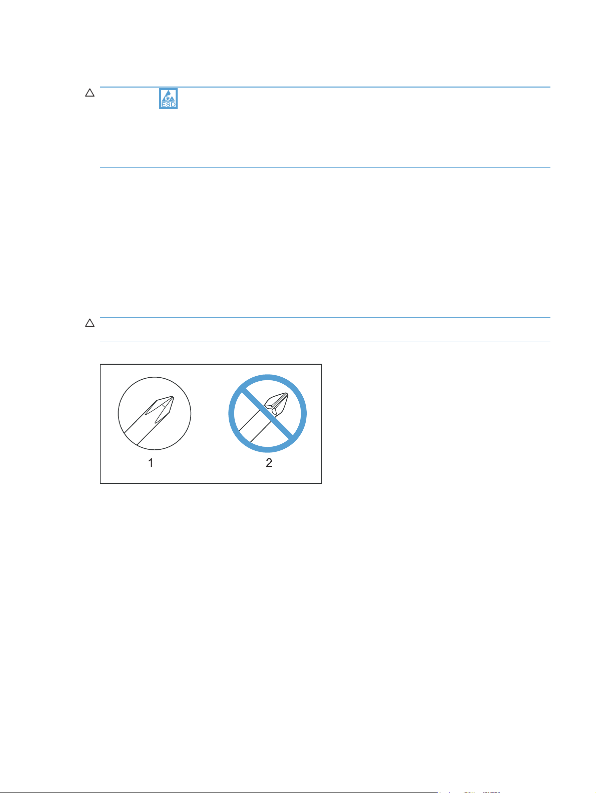
CAUTION: Always use a Phillips screwdriver (callout 1). Do not use a Pozidriv screwdriver
(callout 2) or any motorized screwdriver. These can damage screws or screw threads.
Figure 1-1 Phillips and Pozidriv screwdriver comparison
Service approach
Before performing service
Remove all paper from the product.
●
Turn off the power using the power switch.
●
Unplug the power cable and interface cable or cables.
●
Place the product on an ESD workstation or mat, or use an ESD strap (if one is available). If an
●
ESD workstation, mat, or strap is not available, ground yourself by touching the sheet-metal
chassis before touching an ESD-sensitive part.
Remove the print cartridge.
●
ENWW Electrostatic discharge 3
Page 21

After performing service
● Plug in the power cable.
● Reinstall the print cartridge.
Load paper in the product.
●
Post-service test
Perform the following test to verify that the repair or replacement was successful.
Print-quality test
1. Verify that you have completed the necessary reassembly steps.
2. Make sure that the tray contains clean, unmarked paper.
3. Attach the power cord and interface cable or interface cables, and then turn on the product.
4. Verify that the expected startup sounds occur.
5. Print a configuration page, and then verify that the expected printing sounds occur.
6. Print a demo page, and then verify that the print quality is as expected.
7. Send a print job from the host computer, and then verify that the output meets expectations.
8. Clean the outside of the product with a damp cloth.
Parts removal order
NOTE: In the following list, parts shown with blue text should be removed only in a clean-room
environment. See the Service Manual Addendum for details about removing and replacing these
parts.
4 Chapter 1 Removal and replacement ENWW
Page 22

Figure 1-2 Parts removal order: Scanner and document feeder
A
utomatic document feeder assembly
ADF tray
ADF top cover
ADF pre-pickup arm and roller
ADF outer cover
ADF cable cover
ADF core
ADF roller post scan pinch
Solar lock
ADF base
Scanner assembly
Control panel
Engine left cover
ADF floating hinge
Scanner bezel (See the Service Manual Addendum)
ADF floating hinge (Also can be removed before the Scanner bezel, tool needed)
Scan-drive system
DC servo motor
Scan bar
Scanner base
SSA hinge
Cartridge door arm
ENWW Service approach 5
Page 23

Figure 1-3 Parts removal order: Product base
Print cartridge
Separation pad
Pickup roller
Transfer roller
Printer side covers
Fax card & formatter
Cartridge door
Front cover
Laser Scanner
Main Motor
Top cover
Duplex door
Duplex frame
Pickup ASSY
Fuser
Pickup solenoid
Engine Controller PCA
Duplex-reverse solenoid
Main fan
Duplexer-connector PCA
6 Chapter 1 Removal and replacement ENWW
Page 24
Removal and replacement procedures
NOTE: Many of the figures in the following procedures show the product with the scanner assembly
removed. However, removal of the scanner assembly is necessary only when specified in the steps.
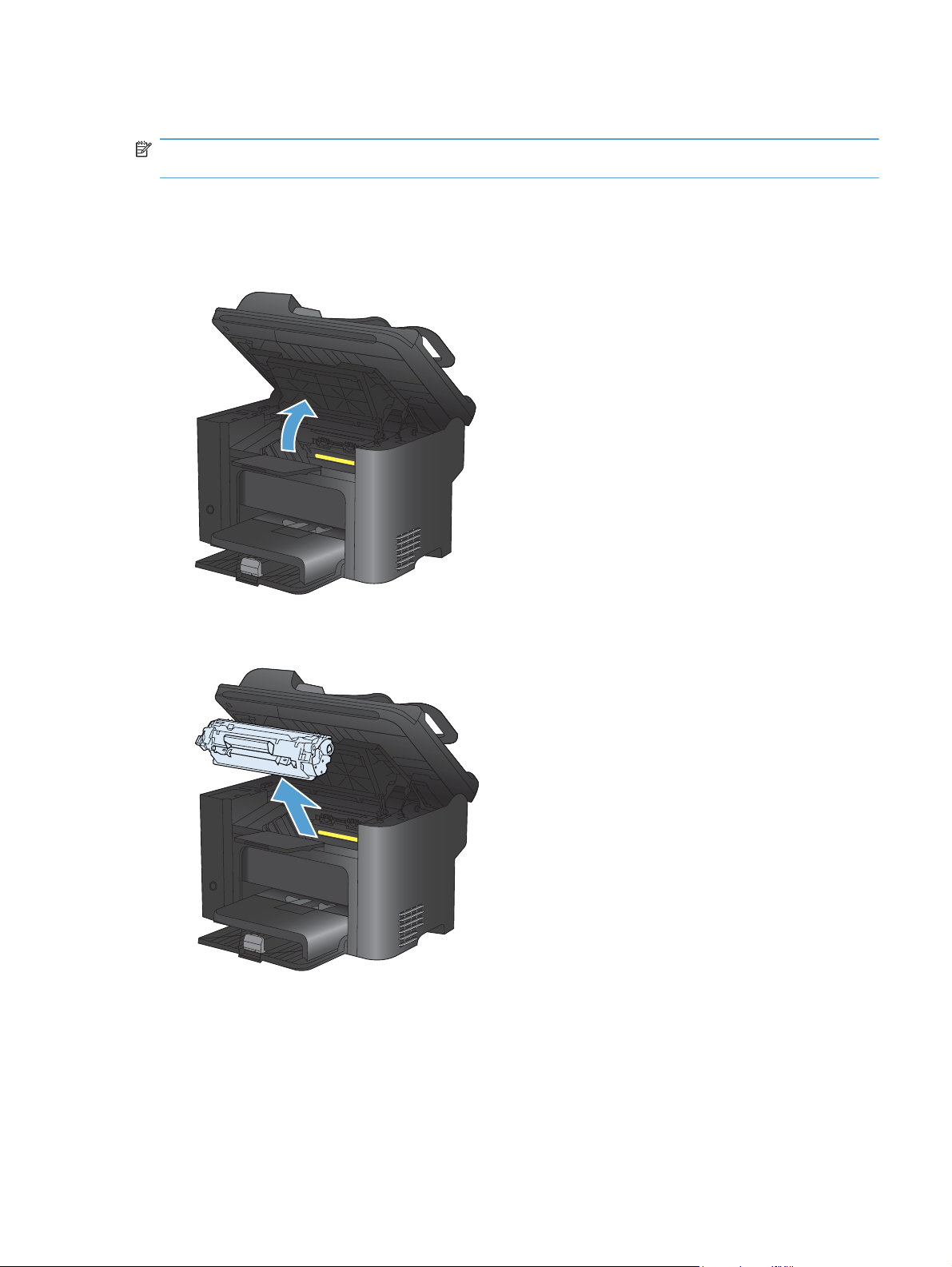
Print cartridge
1. Lift the scanner assembly, and then open the cartridge door.
Figure 1-4 Remove the print cartridge (1 of 2)
2. Remove the print cartridge.
Figure 1-5 Remove the print cartridge (2 of 2)
ENWW Removal and replacement procedures 7
Page 25
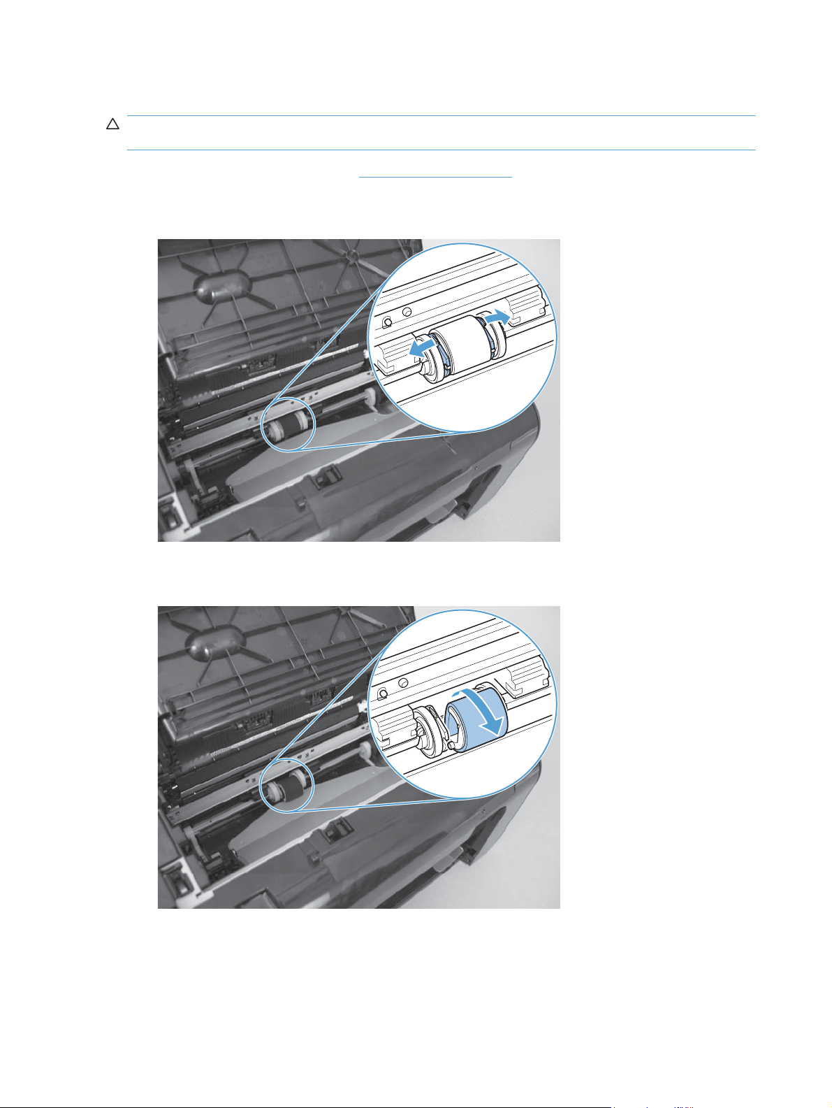
Pickup roller
CAUTION: Do not touch the sponge portion of the roller. Skin oils can cause paper handling
problems.
1. Remove the print cartridge. See Print cartridge on page 7.
2. Release the two tabs between the wheels and the sides of the pick up roller.
Figure 1-6 Remove the pickup roller (1 of 2)
3. Rotate the roller away from the product to remove it.
Figure 1-7 Remove the pickup roller (2 of 2)
8 Chapter 1 Removal and replacement ENWW
Page 26
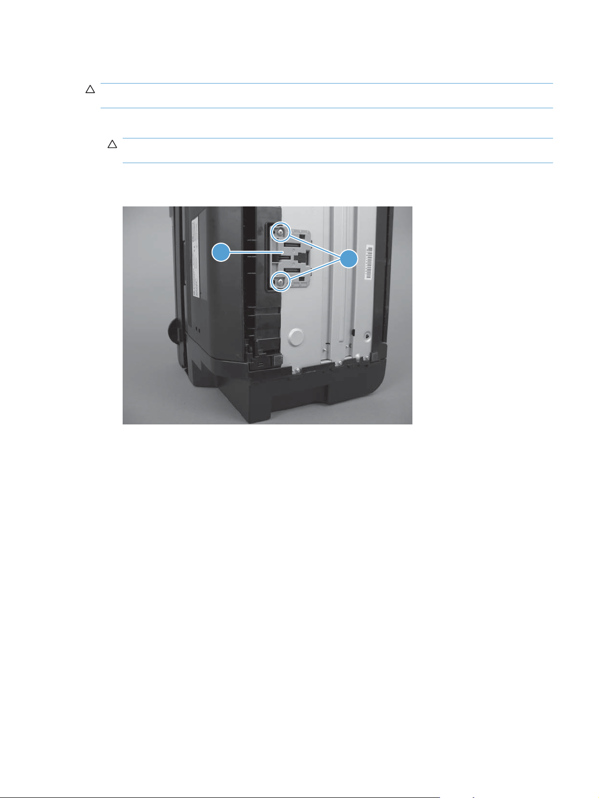
Separation pad
CAUTION: Do not touch the sponge portion of the pad. Skin oils can cause paper handling
problems.
1. Place the product on its side to access the separation pad assembly.
CAUTION: Do not scratch the product covers. Place the product on a cloth or other clean
surface to avoid scratches from dirt and debris.
2. Remove two screws (callout 1), and then remove the separation pad assembly (callout 2).
Figure 1-8 Remove the separation pad assembly
2
1
ENWW Removal and replacement procedures 9
Page 27
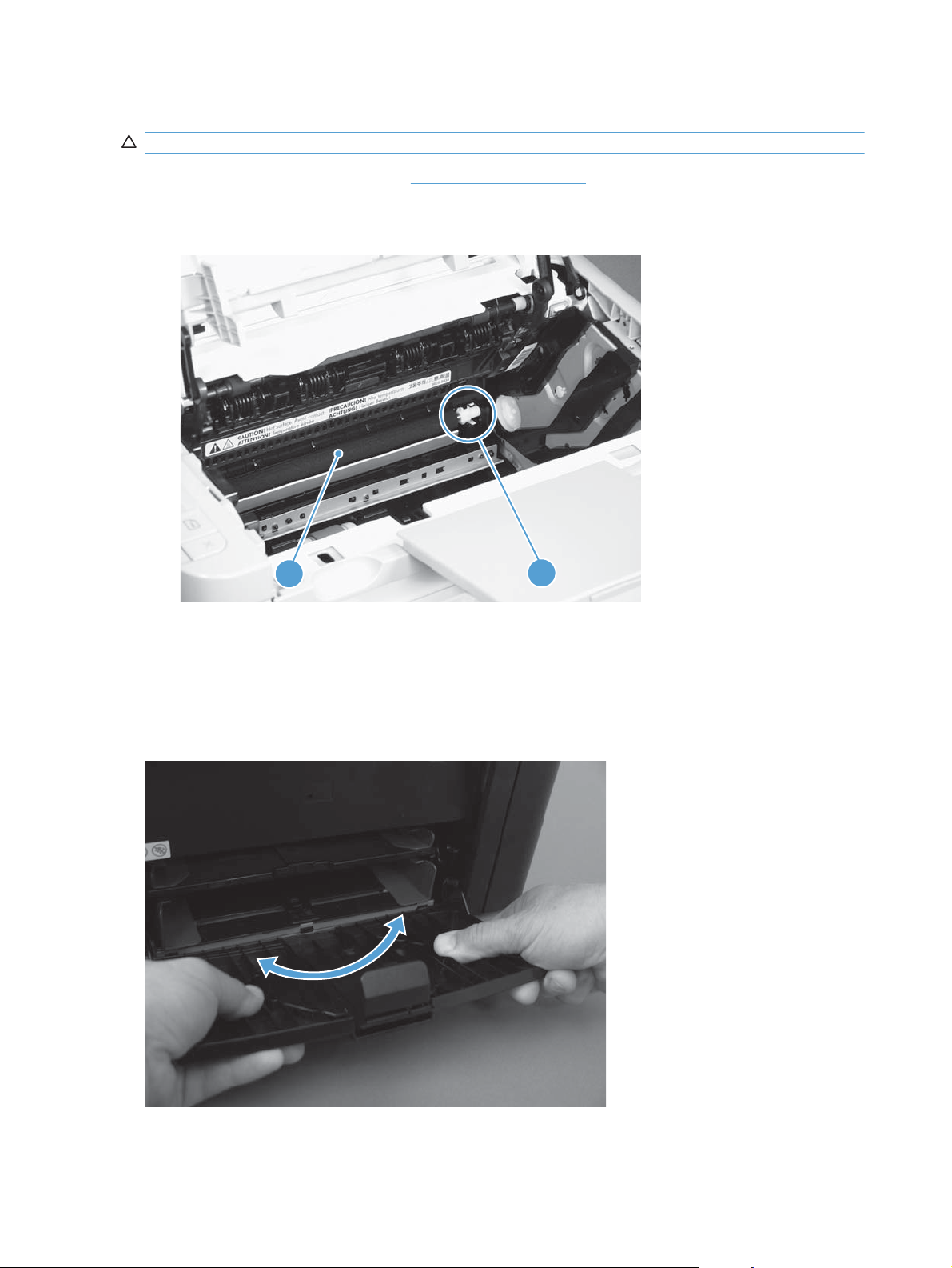
Transfer roller
CAUTION: Do not touch the sponge portion of the roller. Skin oils can cause print quality problems.
1. Remove the print cartridge. See Print cartridge on page 7.
2. Release two tabs (callout 1), and then remove the transfer roller (callout 2).
Figure 1-9 Remove the transfer roller
Covers
Main tray
2
Open the tray, carefully flex the tray to release the hinges, and then remove the tray.
Figure 1-10 Remove the tray
1
10 Chapter 1 Removal and replacement ENWW
Page 28
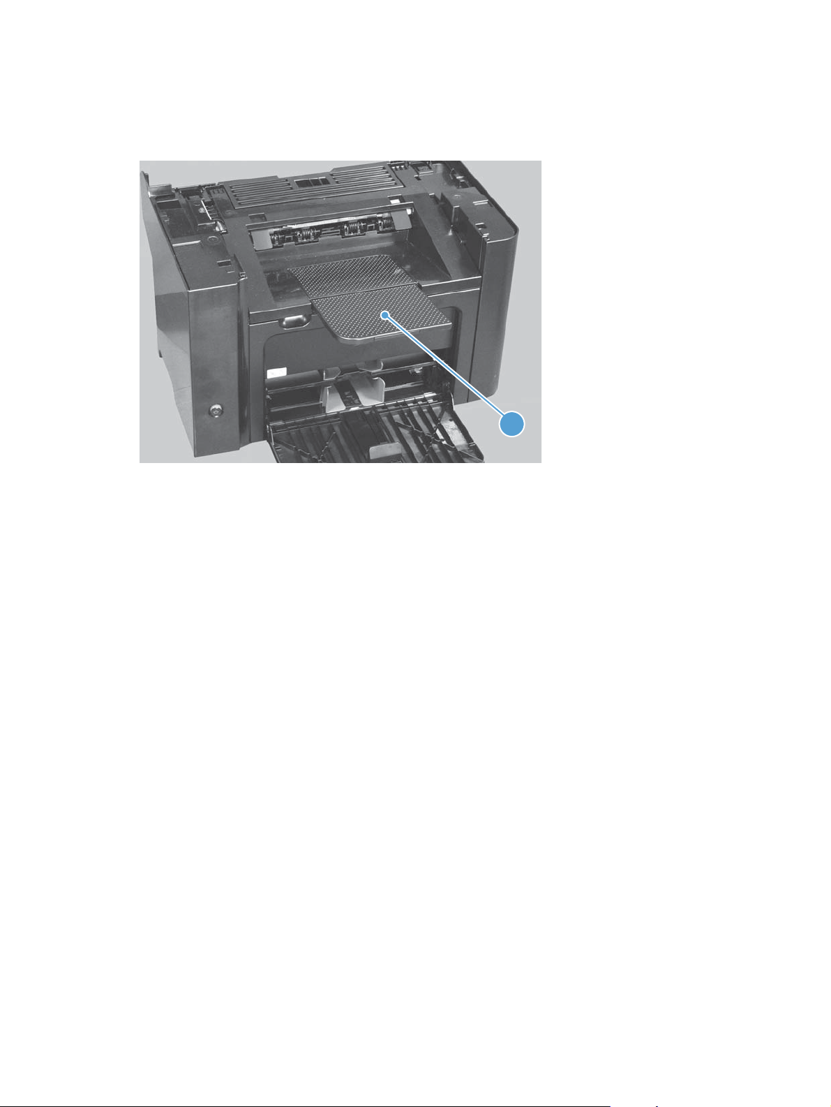
Output bin extension
Lift the output bin extension (callout 1) up to remove it.
Figure 1-11 Remove the output bin extension
1
ENWW Removal and replacement procedures 11
Page 29
Left cover
Before proceeding, remove the following components:
Main tray. See
●
Output bin extension. See
●
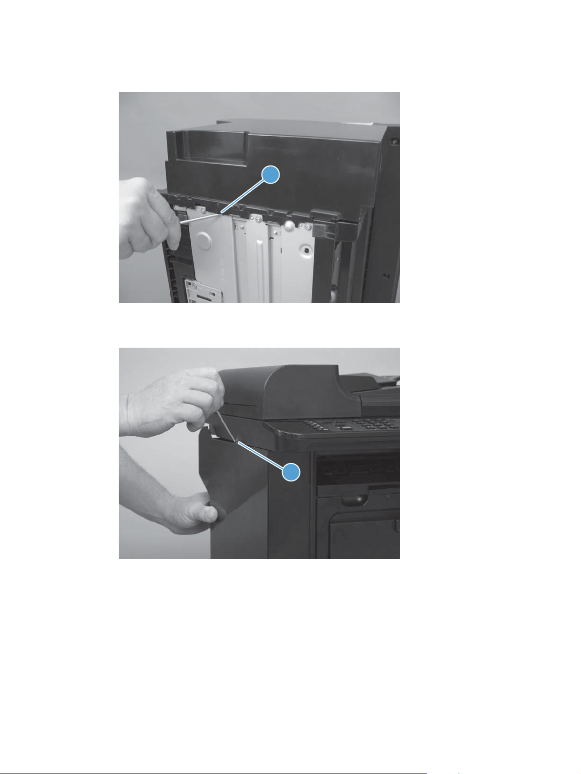
Remove the left cover
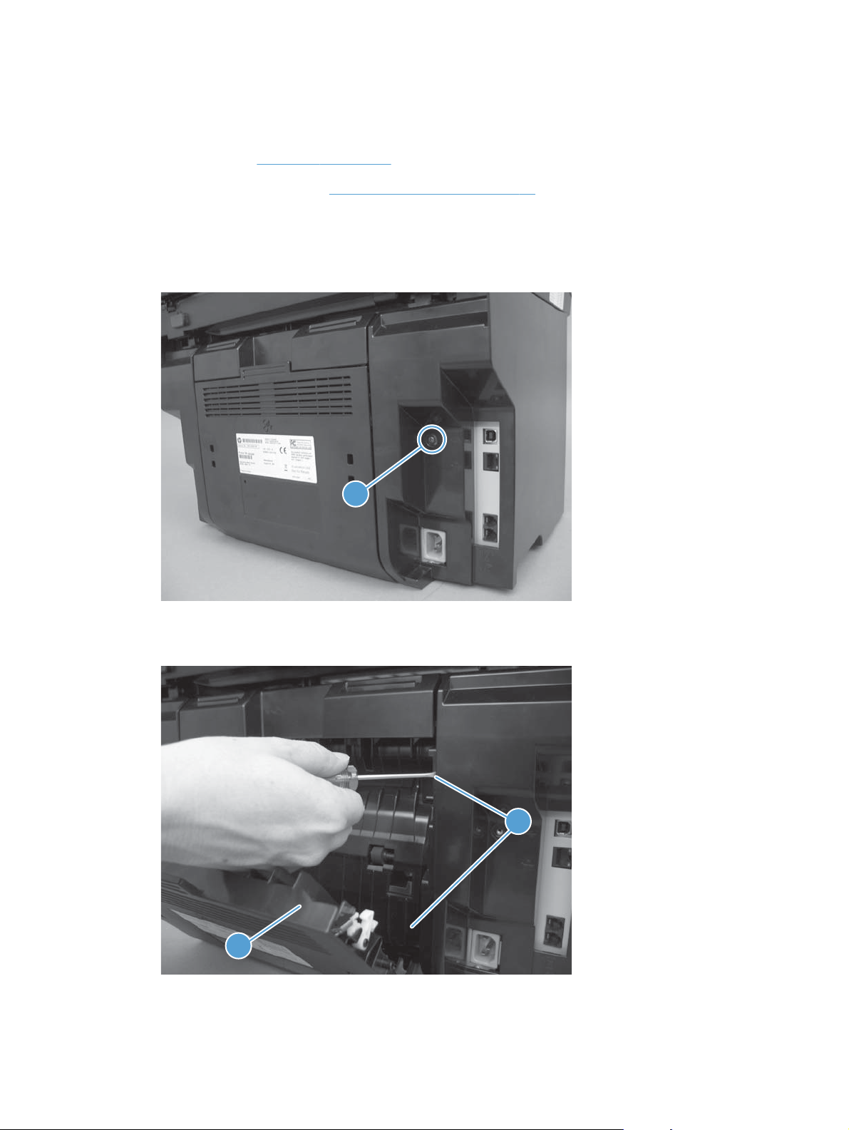
1. Remove one screw (callout 1).
Figure 1-12 Remove the left cover (1 of 5)
Main tray on page 10.
Output bin extension on page 11.
1
2. Open the duplex door (callout 1), and then release two tabs (callout 2).
Figure 1-13 Remove the left cover (2 of 5)
2
1
12 Chapter 1 Removal and replacement ENWW
Page 30
3. Release one tab (callout 1) at the bottom edge of the cover.
Figure 1-14 Remove the left cover (3 of 5)
1
4. Release one tab (callout 1).
Figure 1-15 Remove the left cover (4 of 5)
1
ENWW Removal and replacement procedures 13
Page 31

5. Rotate the back edge of the cover away from the product, and then remove the cover (callout 1).
Figure 1-16 Remove the left cover (5 of 5)
1
14 Chapter 1 Removal and replacement ENWW
Page 32

Scanner assembly
Before proceeding, remove the following components:
Main tray. See
●
Output bin extension. See
●
Left cover. See
●
Remove the scanner assembly
1. Remove one screw (callout 1), and then disconnect three FFCs (callout 2).
Figure 1-17 Remove the scanner assembly (1 of 5)
Main tray on page 10.
Left cover on page 12.
1
Output bin extension on page 11.
2
2. Remove two FFCs from the ferrite cores (callout 1).
Figure 1-18 Remove the scanner assembly (2 of 5)
1
ENWW Removal and replacement procedures 15
Page 33

3. Remove the white FFC from its guide, and then carefully remove three FFCs from the upper
guide (callout 1).
Figure 1-19 Remove the scanner assembly (3 of 5)
1
4. Release the tabs inside the hinges (callout 1) to allow the scanner assembly to slide down on
the hinges.
Figure 1-20 Remove the scanner assembly (4 of 5)
1
16 Chapter 1 Removal and replacement ENWW
Page 34

5. Lift the scanner assembly up (arrow 1) and away from the hinges (arrow 2).
Figure 1-21 Remove the scanner assembly (5 of 5)
Scanner hinges
1. Remove the scanner assembly. See Scanner assembly on page 15.
2
1
2. Remove one screw (callout 1) from each hinge.
Figure 1-22 Remove the scanner hinges (1 of 2)
1
ENWW Removal and replacement procedures 17
Page 35

3. Lift each hinge up to remove it.
Figure 1-23 Remove the scanner hinges (2 of 2)
18 Chapter 1 Removal and replacement ENWW
Page 36

Right cover
Before proceeding, remove the following components:
Main tray. See
●
Output bin extension. See
●
Remove the right cover
1. Remove one screw (callout 1).
Figure 1-24 Remove the right cover (1 of 5)
Main tray on page 10.
Output bin extension on page 11.
1
2. Open the duplex door (callout 1), and then release two tabs (callout 2).
Figure 1-25 Remove the right cover (2 of 5)
2
1
ENWW Removal and replacement procedures 19
Page 37

3. Release one tab (callout 1) at the bottom edge of the cover.
Figure 1-26 Remove the right cover (3 of 5)
1
4. Release one tab (callout 1) at the top of the right cover.
Figure 1-27 Remove the right cover (4 of 5)
1
20 Chapter 1 Removal and replacement ENWW
Page 38

5. Pull the rear edge of the cover away from the product, slide the cover toward the front of the
product to release it, and then remove the cover (callout 1).
Figure 1-28 Remove the right cover (5 of 5)
1
ENWW Removal and replacement procedures 21
Page 39

Duplex door
Open the duplex door (callout 1), release one of the hinges (callout 2) by pushing inward on the door
retainer. Swing the door away from the product to release the second hinge, and then remove the
door.
Figure 1-29 Remove the duplex door
2
1
22 Chapter 1 Removal and replacement ENWW
Page 40

Duplex frame
Before proceeding, remove the following components:
Left cover. See
●
Right cover. See
●
Duplex door. See
●
Remove the duplex frame
1. Remove four screws (callout 1).
Figure 1-30 Remove the duplex frame (1 of 2)
Left cover on page 12.
Right cover on page 19.
Duplex door on page 22.
1
2. Release three tabs (callout 1), slide the duplex frame down (callout 2), and then remove the
duplex frame.
Figure 1-31 Remove the duplex frame (2 of 2)
2
1
ENWW Removal and replacement procedures 23
Page 41

Cartridge door
Before proceeding, remove the following components:
Main tray. See
●
Output bin extension. See
●
Left cover. See
●
Scanner assembly. See
●
Remove the cartridge door
CAUTION: The cartridge door connecting arms can easily come apart once the cartridge door is
removed. Do not lose the cartridge door arms while servicing the product.
1. Open the cartridge door, and then squeeze together the tabs (callout 1) on the right side link arm
(callout 2).
Figure 1-32 Remove the cartridge door (1 of 5)
Main tray on page 10.
Output bin extension on page 11.
Left cover on page 12.
Scanner assembly on page 15.
1
2
24 Chapter 1 Removal and replacement ENWW
Page 42

2. Squeeze together the tabs (callout 1) on the cartridge door open indicator arm (callout 2) to
release it from the door.
Figure 1-33 Remove the cartridge door (2 of 5)
1
2
3. Squeeze together the tabs (callout 1) on the left side link arm (callout 2) to release it from the
door.
Figure 1-34 Remove the cartridge door (3 of 5)
1
2
ENWW Removal and replacement procedures 25
Page 43

4. Squeeze together the tabs (callout 1) on the cartridge door lift arm (callout 2) to release it from
the door.
Figure 1-35 Remove the cartridge door (4 of 5)
1
2
5. Lift the cartridge door straight up (callout 1), and then remove it .
Figure 1-36 Remove the cartridge door (5 of 5)
1
26 Chapter 1 Removal and replacement ENWW
Page 44

Front cover
Before proceeding, remove the following components:
Main tray. See
●
Output bin extension. See
●
Left cover. See
●
Right cover. See
●
Remove the front cover
Release two tabs (callout 1), and then pull the bottom edge of the front cover (callout 2) away
▲
from the product to remove it.
Figure 1-37 Remove the front cover
Main tray on page 10.
Output bin extension on page 11.
Left cover on page 12.
Right cover on page 19.
2
1
ENWW Removal and replacement procedures 27
Page 45

Upper cover
Before proceeding, remove the following components:
Main tray. See
●
Output bin extension. See
●
Left cover. See
●
Right cover. See
●
Scanner assembly. See
●
Cartridge door. See
●
Front cover. See
●
Remove the upper cover
Remove four screws (callout 1), and then remove the upper cover (callout 2).
▲
CAUTION: Do not lose the cartridge door arms while servicing the product. The cartridge door
connecting arms can easily come apart once the cartridge door is removed.
Figure 1-38 Remove the upper cover
Main tray on page 10.
Output bin extension on page 11.
Left cover on page 12.
Right cover on page 19.
Scanner assembly on page 15.
Cartridge door on page 24.
Front cover on page 27.
2
1
28 Chapter 1 Removal and replacement ENWW
Page 46

Main assemblies
Formatter PCA
Before proceeding, remove the following components:
● Main tray. See
● Output bin extension. See
Left cover. See
●
Remove the formatter PCA
1. Disconnect three FFCs (callout 1).
Figure 1-39 Remove the formatter PCA (1 of 2)
Main tray on page 10.
Output bin extension on page 11.
Left cover on page 12.
1
ENWW Removal and replacement procedures 29
Page 47

2. Remove five screws (callout 1), disconnect one connector (callout 2), disconnect two FFCs
(callout 3), and then remove the formatter PCA.
Figure 1-40 Remove the formatter PCA (2 of 2)
1
2
3
30 Chapter 1 Removal and replacement ENWW
Page 48

Fax PCA
Before proceeding, remove the following components:
Main tray. See
●
Output bin extension. See
●
Left cover. See
●
Remove the fax PCA
Remove one FFC (callout 1), remove four screws (callout 2), and then remove the fax PCA.
▲
Figure 1-41 Remove the fax PCA
Main tray on page 10.
Output bin extension on page 11.
Left cover on page 12.
1
2
ENWW Removal and replacement procedures 31
Page 49

Laser scanner assembly
Before proceeding, remove the following components:
Main tray. See
●
Output bin extension. See
●
Left cover. See
●
Scanner assembly. See
●
Right cover. See
●
Front cover. See
●
Cartridge door. See
●
Upper cover. See
●
Remove the laser scanner assembly
1. Release one tab (callout 1), and then slide the holder (callout 2) forward to remove it.
Figure 1-42 Remove the laser scanner assembly (1 of 5)
Main tray on page 10.
Left cover on page 12.
Right cover on page 19.
Front cover on page 27.
Cartridge door on page 24.
Upper cover on page 28.
Output bin extension on page 11.
Scanner assembly on page 15.
1
2
32 Chapter 1 Removal and replacement ENWW
Page 50

2. Remove four screws (callout 1), and then remove the laser scanner cover (callout 2) and the
sheet-metal plate (callout 3) together.
CAUTION: The laser scanner cover (callout 2) and sheet-metal plate (callout 3) can be easily
separated. Do not lose the plate while servicing the product.
TIP: When the cover is reinstalled, make sure that the black screws (callout 4) are installed in
the correct holes.
Figure 1-43 Remove the laser scanner assembly (2 of 5)
4
1
2
3. Disconnect one FFC (callout 1), and then remove four screws (callout 2).
Figure 1-44 Remove the laser scanner assembly (3 of 5)
3
2
1
ENWW Removal and replacement procedures 33
Page 51

4. Slide the laser scanner assembly to the left, and then remove the dust-proof sponge (callout 1).
Figure 1-45 Remove the laser scanner assembly (4 of 5)
1
5. Disconnect one connector (callout 1), and then remove the laser scanner assembly (callout 2).
Figure 1-46 Remove the laser scanner assembly (5 of 5)
1
2
34 Chapter 1 Removal and replacement ENWW
Page 52

Reinstall the laser scanner assembly
▲ When the holder is reinstalled (callout 1), make sure that the lever arm (callout 2) is correctly
positioned in the slot in the holder.
Figure 1-47 Reinstall the laser scanner assembly
1
2
ENWW Removal and replacement procedures 35
Page 53

Pickup assembly
Before proceeding, remove the following components:
Main tray. See
●
Output bin extension. See
●
Separation pad. See
●
Left cover. See
●
Scanner assembly. See
●
Formatter PCA. See
●
Fax modem. See
●
Right cover. See
●
Duplex frame. See
●
Cartridge door. See
●
Front cover. See
●
Upper cover. See
●
Remove the pickup assembly
1. Release two tabs (callout 1), and then remove the duplex reverse guide (callout 2).
Main tray on page 10.
Output bin extension on page 11.
Separation pad on page 9.
Left cover on page 12.
Scanner assembly on page 15.
Formatter PCA on page 29.
Fax PCA on page 31.
Right cover on page 19.
Duplex frame on page 23.
Cartridge door on page 24.
Front cover on page 27.
Upper cover on page 28.
Figure 1-48 Remove the pickup assembly (1 of 9)
1
2
36 Chapter 1 Removal and replacement ENWW
Page 54

2. Remove two screws (callout 1), and then remove the sheet metal corner brace (callout 2).
Figure 1-49 Remove the pickup assembly (2 of 9)
2
1
3. Disconnect one connector (callout 1), remove the wire harness from the guides (callout 2), and
then remove five screws (callout 3).
NOTE: The connector in callout 1 is the lower of the two connectors in this area. The right-
most screw in callout 3 is on the front of the product.
Figure 1-50 Remove the pickup assembly (3 of 9)
1
2
3
ENWW Removal and replacement procedures 37
Page 55

4. Disconnect one connector (callout 1), and then release the wire harness (callout 2) from the
guides (callout 3).
Figure 1-51 Remove the pickup assembly (4 of 9)
3
2
1
5. Disconnect three connectors (callout 1), and then remove the wire harness (callout 2) from the
guide (callout 3).
Reinstallation tip When installing the pickup assembly, place these wire harnesses (callout 2)
in the guide first, and then place the wire harness from the ground connector in the previous
step. This ensures that the harnesses are long enough to reach the engine controller PCA
connectors.
Figure 1-52 Remove the pickup assembly (5 of 9)
2
3
1
38 Chapter 1 Removal and replacement ENWW
Page 56

6. Remove one bushing (callout 1) by releasing the tab and rotating the bushing counter-clockwise.
Figure 1-53 Remove the pickup assembly (6 of 9)
2
1
7. Remove one screw with a star washer (callout 1).
Figure 1-54 Remove the pickup assembly (7 of 9)
1
ENWW Removal and replacement procedures 39
Page 57

8. Remove six screws (callout 1), and then remove the pickup assembly (callout 2).
CAUTION: The ground spring on the assembly is not captive. Do not lose the spring when
removing the assembly. See
Figure 1-55 Remove the pickup assembly (8 of 9)
Reinstall the pickup assembly on page 41.
1
2
9. Remove one gear (callout 1) from the pickup assembly (callout 2).
CAUTION: The gear is not captive. Do not lose the gear while servicing the product.
Figure 1-56 Remove the pickup assembly (9 of 9)
2
1
40 Chapter 1 Removal and replacement ENWW
Page 58

Reinstall the pickup assembly
1. Make sure that the pickup assembly ground spring is positioned correctly when reinstalling the
assembly.
Figure 1-57 Reinstall the pickup assembly (1 of 4; correct ground spring position)
Figure 1-58 Reinstall the pickup assembly (2 of 4; incorrect ground spring position)
ENWW Removal and replacement procedures 41
Page 59

2. Push down the lift plate before installing the pickup assembly.
TIP: Reach in from the front of the product to push and hold down the lift plate while installing
the pickup unit.
Figure 1-59 Reinstall the pickup assembly (3 of 4; lift plate in raised position)
Figure 1-60 Reinstall the pickup assembly (4 of 4; lift plate in lowered position)
42 Chapter 1 Removal and replacement ENWW
Page 60

Fuser
Before proceeding, remove the following components:
Main tray. See
●
Output bin extension. See
●
Left cover. See
●
Scanner assembly. See
●
Formatter PCA. See
●
Fax modem. See
●
Right cover. See
●
Duplex frame. See
●
Front cover. See
●
Cartridge door. See
●
Upper cover. See
●
Remove the fuser
1. Release two tabs (callout 1), and then remove the duplex reverse guide (callout 2).
Figure 1-61 Remove the fuser (1 of 9)
Main tray on page 10.
Output bin extension on page 11.
Left cover on page 12.
Scanner assembly on page 15.
Formatter PCA on page 29.
Fax PCA on page 31.
Right cover on page 19.
Duplex frame on page 23.
Front cover on page 27.
Cartridge door on page 24.
Upper cover on page 28.
1
2
ENWW Removal and replacement procedures 43
Page 61

2. Remove two screws (callout 1), and then remove the sheet-metal corner brace (callout 2).
Figure 1-62 Remove the fuser (2 of 9)
2
1
3. Disconnect one connector (callout 1), remove one wire harness from the guide (callout 2), and
then remove five screws (callout 3) to remove the sheet metal plate.
Figure 1-63 Remove the fuser (3 of 9)
3
1
2
44 Chapter 1 Removal and replacement ENWW
Page 62

4. Disconnect one connector (callout 1), and then release the wire harness (callout 2) from the
guides (callout 3).
Figure 1-64 Remove the fuser (4 of 9)
3
2
1
5. Disconnect four connectors (callout 1), and then release the wire harnesses (callout 2) from the
guide (callout 3).
Figure 1-65 Remove the fuser (5 of 9)
3
1
2
ENWW Removal and replacement procedures 45
Page 63

6. Disconnect one tab (callout 1), and then remove the guide (callout 2).
Figure 1-66 Remove the fuser (6 of 9)
1
2
7. Release the wire harnesses (callout 1) from the guide (callout 2).
Figure 1-67 Remove the fuser (7 of 9)
2
1
46 Chapter 1 Removal and replacement ENWW
Page 64

8. Remove two screws (callout 1), remove the sheet metal brace (callout 2), and then remove one
bushing (callout 3) by releasing the tab and rotating the bushing clockwise.
Figure 1-68 Remove the fuser (8 of 9)
3
1
2
9. Remove three screws (callout 1), and then remove the fuser (callout 2).
Figure 1-69 Remove the fuser (9 of 9)
1
2
ENWW Removal and replacement procedures 47
Page 65

Reinstall the fuser
To avoid damage to the wire harnesses, make sure that they are installed correctly.
Figure 1-70 Reinstall the fuser (1 of 2); correct wire harness installation
Figure 1-71 Reinstall the fuser (2 of 2); incorrect wire harness installation
NOTE: Also make sure the gears are meshed correctly before tightening the screws.
48 Chapter 1 Removal and replacement ENWW
Page 66

Main motor
Before proceeding, remove the following components:
Main tray. See
●
Output bin extension. See
●
Left cover. See
●
Scanner assembly. See
●
Right cover. See
●
Cartridge door. See
●
Front cover. See
●
Upper cover. See
●
Remove the main motor
1. Release one tab (callout 1), and then slide the holder forward (callout 2), and lift it up to remove
it.
Figure 1-72 Remove the main motor (1 of 9)
Main tray on page 10.
Output bin extension on page 11.
Left cover on page 12.
Scanner assembly on page 15.
Right cover on page 19.
Cartridge door on page 24.
Front cover on page 27.
Upper cover on page 28.
1
2
ENWW Removal and replacement procedures 49
Page 67

2. Remove four screws (callout 1), and then remove the laser scanner cover (callout 2) and the
sheet-metal plate (callout 3).
NOTE: The laser scanner cover and plate are removed as one assembly.
TIP: Make sure that the black screws (callout 4) are installed in the correct holes when
reinstalling the laser scanner cover.
Figure 1-73 Remove the main motor (2 of 9)
4
1
2
3. Disconnect three connectors (callout 1 and callout 2).
Figure 1-74 Remove the main motor (3 of 9)
2
3
1
50 Chapter 1 Removal and replacement ENWW
Page 68

4. Release two tabs (callout 1), and then slightly separate the motor driver PCA (callout 2) from the
product.
CAUTION: The motor driver PCA is still connected to the product by the wire harnesses and
an FFC.
Figure 1-75 Remove the main motor (4 of 9)
1
2
5. Duplex models only: Release one tab (callout 1), and then remove the duplex connector PCA
(callout 2).
Figure 1-76 Remove the main motor (5 of 9)
1
2
ENWW Removal and replacement procedures 51
Page 69

6. Disconnect two connectors (callout 1), and then carefully set the PCA out of the way.
CAUTION: Do not damage the FFC that is attached to the PCA.
Figure 1-77 Remove the main motor (6 of 9)
1
7. Release the wire harness (callout 1) from the guide (callout 2).
Figure 1-78 Remove the main motor (7 of 9)
1
2
52 Chapter 1 Removal and replacement ENWW
Page 70

8. Remove one screw (callout 1), and then remove the motor cover (callout 2).
Figure 1-79 Remove the main motor (8 of 9)
1
2
9. Remove two screws (callout 1), and then remove the motor (callout 2).
Figure 1-80 Remove the main motor (9 of 9)
1
2
ENWW Removal and replacement procedures 53
Page 71

Reinstall the main motor drive belt
▲ When the main motor is reinstalled, make sure that the drive belt (callout 1) is positioned
correctly over the tensioner roller (callout 2).
Figure 1-81 Main motor drive belt installed correctly
2
Figure 1-82 Main motor drive belt installed incorrectly
1
2
1
54 Chapter 1 Removal and replacement ENWW
Page 72

Pickup solenoid
Before proceeding, remove the following components:
Main tray. See
●
Output bin extension. See
●
Left cover. See
●
Scanner assembly. See
●
Formatter PCA. See
●
Fax modem. See
●
Right cover. See
●
Duplex frame. See
●
Cartridge door. See
●
Front cover. See
●
Upper cover. See
●
Remove the pickup solenoid
1. Release two tabs (callout 1), and then remove the duplex reverse guide (callout 2).
Figure 1-83 Remove the pickup solenoid (1 of 6)
Main tray on page 10.
Output bin extension on page 11.
Left cover on page 12.
Scanner assembly on page 15.
Formatter PCA on page 29.
Fax PCA on page 31.
Right cover on page 19.
Duplex frame on page 23.
Cartridge door on page 24.
Front cover on page 27.
Upper cover on page 28.
1
2
ENWW Removal and replacement procedures 55
Page 73

2. Remove two screws (callout 1), and then remove the sheet-metal corner brace (callout 2).
Figure 1-84 Remove the pickup solenoid (2 of 6)
2
1
3. Disconnect one connector (callout 1), remove one wire harness from the guide (callout 2), and
then remove five screws (callout 3) to remove the sheet metal plate.
Figure 1-85 Remove the pickup solenoid (3 of 6)
1
2
3
56 Chapter 1 Removal and replacement ENWW
Page 74

4. Disconnect one connector (callout 1), and then remove the wire harness (callout 2) from the
guide (callout 3).
NOTE: Callout 1 indicates three connectors. Disconnect the one that is furthest to the left
(J562).
Figure 1-86 Remove the pickup solenoid (4 of 6)
3
2
1
5. Release the wire harness (callout 1) from the guide (callout 2).
Figure 1-87 Remove the pickup solenoid (5 of 6)
2
1
ENWW Removal and replacement procedures 57
Page 75

6. Remove one screw (callout 1), and then remove the pickup solenoid (callout 2).
Figure 1-88 Remove the pickup solenoid (6 of 6)
1
2
58 Chapter 1 Removal and replacement ENWW
Page 76

Engine controller PCA
Before proceeding, remove the following components:
Main tray. See
●
Output bin extension. See
●
Left cover. See
●
Scanner assembly. See
●
Formatter PCA. See
●
Fax modem. See
●
Right cover. See
●
Duplex frame. See
●
Cartridge door. See
●
Front cover. See
●
Upper cover. See
●
Remove the engine controller PCA
1. Release two tabs (callout 1), and then remove the duplex reverse guide (callout 2).
Figure 1-89 Remove the engine controller PCA (1 of 9)
Main tray on page 10.
Left cover on page 12.
Fax PCA on page 31.
Right cover on page 19.
Duplex frame on page 23.
Front cover on page 27.
Upper cover on page 28.
Output bin extension on page 11.
Scanner assembly on page 15.
Formatter PCA on page 29.
Cartridge door on page 24.
1
2
ENWW Removal and replacement procedures 59
Page 77

2. Remove two screws (callout 1), and then remove the sheet-metal corner brace (callout 2).
Figure 1-90 Remove the engine controller PCA (2 of 9)
2
1
3. Disconnect one connector (callout 1), remove one wire harness from the guide, (callout 2), and
then remove five screws (callout 3) to remove the sheet metal plate.
Figure 1-91 Remove the engine controller PCA (3 of 9)
1
2
3
60 Chapter 1 Removal and replacement ENWW
Page 78

4. Disconnect one connector (callout 1), and then release the wire harness (callout 2) from the
guides (callout 3).
Figure 1-92 Remove the engine controller PCA (4 of 9)
3
2
1
5. Disconnect four connectors (callout 1), and then remove the wire harnesses (callout 2) from the
guide (callout 3).
Figure 1-93 Remove the engine controller PCA (5 of 9)
3
1
2
ENWW Removal and replacement procedures 61
Page 79

6. Release the wire harness (callout 1) from the ground spring (callout 2).
Figure 1-94 Remove the engine controller PCA (6 of 9)
2
7. Disconnect two connectors (callout 1) and two FFCs (callout 2).
Figure 1-95 Remove the engine controller PCA (7 of 9)
1
2
1
62 Chapter 1 Removal and replacement ENWW
Page 80

8. Remove one screw with star washer (callout 1), and then remove one more screw (callout 2).
Figure 1-96 Remove the engine controller PCA (8 of 9)
1
2
9. Remove three screws with washers (callout 1), and then remove the engine controller PCA
(callout 2).
Figure 1-97 Remove the engine controller PCA (9 of 9)
2
1
ENWW Removal and replacement procedures 63
Page 81

Reinstall the engine controller PCA
NOTE: To install the transfer wire harness correctly, follow these steps in addition to the steps in
reverse order of removal.
1. Place the engine controller PCA into the product so that the cartridge door switch lever (callout
1) engages correctly with the switch on the PCA (callout 2).
Figure 1-98 Reinstall the engine controller PCA (1 of 5)
1
2
2. Set the ground spring (callout 1) on the transfer wire harness (callout 2).
Figure 1-99 Reinstall the engine controller PCA (2 of 5)
2
1
64 Chapter 1 Removal and replacement ENWW
Page 82

3. Position the transfer wire harness (callout 1) in the guide (callout 2).
Figure 1-100 Reinstall the engine controller PCA (3 of 5)
2
1
4. Connect one connector (callout 1).
Figure 1-101 Reinstall the engine controller PCA (4 of 5)
1
ENWW Removal and replacement procedures 65
Page 83

5. Position the transfer wire harness (callout 1) in the guides (callout 2).
Figure 1-102 Reinstall the engine controller PCA (5 of 5)
2
1
66 Chapter 1 Removal and replacement ENWW
Page 84

Duplex reverse solenoid
Before proceeding, remove the following components:
Main tray. See
●
Output bin extension. See
●
Left cover. See
●
Scanner assembly. See
●
Right cover. See
●
Cartridge door. See
●
Front cover. See
●
Upper cover. See
●
Remove the duplex reverse solenoid
1. Release one tab (callout 1), and then remove the holder (callout 2).
Figure 1-103 Remove the duplex reverse solenoid (1 of 5)
Main tray on page 10.
Left cover on page 12.
Right cover on page 19.
Cartridge door on page 24.
Front cover on page 27.
Upper cover on page 28.
Output bin extension on page 11.
Scanner assembly on page 15.
1
2
ENWW Removal and replacement procedures 67
Page 85

2. Remove four screws (callout 1), and then remove the laser scanner cover (callout 2) and the
sheet metal plate (callout 3).
NOTE: The laser scanner cover and plate are removed as one assembly.
TIP: When installing the laser scanner cover, make sure that the black screws (callout 4) are in
the correct holes.
Figure 1-104 Remove the duplex reverse solenoid (2 of 5)
4
1
2
3. Disconnect two connectors (callout 1), and then release the wire harness (callout 2) from the
guides (callout 3).
Figure 1-105 Remove the duplex reverse solenoid (3 of 5)
3
1
3
2
68 Chapter 1 Removal and replacement ENWW
Page 86

4. Release one tab (callout 1), and then rotate the cable guide forward to remove it (callout 2).
Figure 1-106 Remove the duplex reverse solenoid (4 of 5)
1
2
5. Remove one screw (callout 1), and then remove the duplex reverse solenoid (callout 2).
Figure 1-107 Remove the duplex reverse solenoid (5 of 5)
1
2
ENWW Removal and replacement procedures 69
Page 87

Main fan
Before proceeding, remove the following components:
Main tray. See
●
Output bin extension. See
●
Left cover. See
●
Scanner assembly. See
●
Right cover. See
●
Cartridge door. See
●
Front cover. See
●
Upper cover. See
●
Remove the main fan
1. Release one tab (callout 1), and then remove the holder (callout 2).
Figure 1-108 Remove the main fan (1 of 5)
Main tray on page 10.
Output bin extension on page 11.
Left cover on page 12.
Scanner assembly on page 15.
Right cover on page 19.
Cartridge door on page 24.
Front cover on page 27.
Upper cover on page 28.
1
2
70 Chapter 1 Removal and replacement ENWW
Page 88

2. Remove four screws (callout 1), and then remove the laser scanner cover (callout 2) and the
sheet-metal plate (callout 3).
NOTE: The laser scanner cover and plate are removed as one assembly.
TIP: When installing the laser scanner cover, make sure that the black screws (callout 4) are in
the correct holes.
Figure 1-109 Remove the main fan (2 of 5)
4
1
2
3. Disconnect one connector (callout 1), and then release the wire harness (callout 2) from the
guides (callout 3).
Figure 1-110 Remove the main fan (3 of 5)
3
1
3
2
ENWW Removal and replacement procedures 71
Page 89

4. Release two tabs (callout 1), and then remove the fan cover (callout 2).
Figure 1-111 Remove the main fan (4 of 5)
1
2
5. Release two tabs (callout 1), and then remove the main fan (callout 2).
Figure 1-112 Remove the main fan (5 of 5)
2
1
72 Chapter 1 Removal and replacement ENWW
Page 90

Reinstall the main fan
When the main fan is reinstalled, make sure that the wire harness (callout 1) is correctly positioned,
and that the label (callout 2) on the fan faces the inside of the product.
Figure 1-113 Reinstall the main fan
1
2
ENWW Removal and replacement procedures 73
Page 91

Duplex connector PCA
Before proceeding, remove the following components:
Main tray. See
●
Output bin extension. See
●
Left cover. See
●
Scanner assembly. See
●
Right cover. See
●
Cartridge door. See
●
Front cover. See
●
Upper cover. See
●
Remove the duplex connector PCA
1. Release one tab (callout 1), and then remove the holder (callout 2).
Figure 1-114 Remove the duplex connector PCA (1 of 5)
Main tray on page 10.
Left cover on page 12.
Right cover on page 19.
Cartridge door on page 24.
Front cover on page 27.
Upper cover on page 28.
Output bin extension on page 11.
Scanner assembly on page 15.
1
2
74 Chapter 1 Removal and replacement ENWW
Page 92

2. Remove four screws (callout 1), and then remove the laser scanner cover (callout 2) and the
sheet-metal plate (callout 3).
NOTE: The laser scanner cover and plate are removed as one assembly.
TIP: When installing the laser scanner cover, make sure that the black screws (callout 4) are in
the correct holes.
Figure 1-115 Remove the duplex connector PCA (2 of 5)
4
1
2
3. Disconnect three connectors (callout 1)
Figure 1-116 Remove the duplex connector PCA (3 of 5)
3
1
ENWW Removal and replacement procedures 75
Page 93

4. Release two tabs (callout 1), and then slightly separate the motor driver PCA (callout 2) from the
product.
CAUTION: Do not damage the FFC and the connectors that are still connected to the motor
driver PCA.
Figure 1-117 Remove the duplex connector PCA (4 of 5)
1
2
5. Release one tab (callout 1), and then remove the duplex connector PCA (callout 2).
Figure 1-118 Remove the duplex connector PCA (5 of 5)
1
2
76 Chapter 1 Removal and replacement ENWW
Page 94

Scanner components
NOTE: This section describes replacement and removal of individual scanner components. To
remove the complete scanner assembly, see
Document feeder input tray
1. Open the document feeder cover.
Figure 1-119 Remove the document feeder input tray (1 of 2)
Scanner assembly on page 15.
2. Hold the scanner cover down, and then pull up on the document feeder tray to release two tabs,
lift the document feeder tray up, and then remove it.
Figure 1-120 Remove the document feeder input tray (2 of 2)
ENWW Removal and replacement procedures 77
Page 95

Document feeder cover
1. Open the document feeder cover.
Figure 1-121 Remove the document feeder cover (1 of 3)
2. Release one tab (callout 1), and then fully open the document feeder cover.
Figure 1-122 Remove the document feeder cover (2 of 3)
1
78 Chapter 1 Removal and replacement ENWW
Page 96

3. Release the hinges (callout 1), and then remove the document feeder cover.
Figure 1-123 Remove the document feeder cover (3 of 3)
1
ENWW Removal and replacement procedures 79
Page 97

Document feeder pick arm assembly
Before proceeding, remove the following components:
Document feeder tray. See
●
Document feeder cover. See
●
Remove the document feeder pick arm assembly
1. Release two tabs (callout 1) on each end of the inner cover (for a total of four tabs), and then lift
the inner cover out of the outer cover.
Figure 1-124 Remove the document feeder pick arm assembly (1 of 4)
Document feeder input tray on page 77.
Document feeder cover on page 78.
1
2. Remove the pick extension shaft (callout 1).
Figure 1-125 Remove the document feeder pick arm assembly (2 of 4)
1
80 Chapter 1 Removal and replacement ENWW
Page 98

3. Release one tab (callout 1).
Figure 1-126 Remove the document feeder pick arm assembly (3 of 4)
1
4. Disconnect the spring that is underneath the pick arm assembly (callout 1), and then rotate the
pick arm assembly to remove it (callout 2).
Figure 1-127 Remove the document feeder pick arm assembly (4 of 4)
2
1
ENWW Removal and replacement procedures 81
Page 99

Document feeder core assembly
Before proceeding, remove the following components:
Document feeder tray. See
●
Document feeder cover. See
●
Remove the document feeder core assembly
1. Release one tab (callout 1), and then remove the document feeder cable cover (callout 2).
Figure 1-128 Remove the document feeder core assembly (1 of 3)
Document feeder input tray on page 77.
Document feeder cover on page 78.
2
1
82 Chapter 1 Removal and replacement ENWW
Page 100

2. Remove one FFC using the blue tab (callout 1).
Figure 1-129 Remove the document feeder core assembly (2 of 3)
1
TIP: The orientation of the FFC is important. When reinstalling it, make sure the blue tab is
toward the product right side. If the FFC is installed upside-down, the document feeder does not
work.
3. Release one hinge (callout 1), and then remove the document feeder core assembly.
Figure 1-130 Remove the document feeder core assembly (3 of 3)
1
ENWW Removal and replacement procedures 83
 Loading...