

HP LaserJet Pro 100 Color MFP M176n, LaserJet Pro 100 Color MFP M177fw Repair Manual
COLOR LASERJET PRO MFP
Repair Manual
OK
X
M176 M177


HP Color LaserJet Pro MFP M176, M177
Repair Manual

Copyright and License
Trademark Credits
© 2013 Copyright Hewlett-Packard
Development Company, L.P.
Reproduction, adaptation, or translation
without prior written permission is prohibited,
except as allowed under the copyright laws.
The information contained herein is subject to
change without notice.
The only warranties for HP products and
services are set forth in the express warranty
statements accompanying such products and
services. Nothing herein should be construed
as constituting an additional warranty. HP shall
not be liable for technical or editorial errors or
omissions contained herein.
Part number: CZ165-90943
Edition 1, 10/2013
Microsoft®, Windows®, Windows® XP, and
Windows Vista® are U.S. registered trademarks
of Microsoft Corporation.

Conventions used in this guide
TIP: Tips provide helpful hints or shortcuts.
NOTE: Notes provide important information to explain a concept or to complete a task.
CAUTION: Cautions indicate procedures that you should follow to avoid losing data or damaging the
product.
WARNING! Warnings alert you to specific procedures that you should follow to avoid personal injury,
catastrophic loss of data, or extensive damage to the product.
ENWW iii

iv Conventions used in this guide ENWW

Table of contents
1 Removal and replacement .............................................................................................................................. 1
Removal and replacement strategy ...................................................................................................................... 2
Introduction ......................................................................................................................................... 2
Required tools ..................................................................................................................................... 2
Types of screws ................................................................................................................................... 3
Service approach ................................................................................................................................................... 4
Before performing service .................................................................................................................. 4
After performing service ..................................................................................................................... 4
Parts removal order ............................................................................................................................ 4
Removal and replacement procedures ................................................................................................................. 5
Customer-replaceable parts ............................................................................................................... 5
Toner cartridges ................................................................................................................ 5
Imaging drum .................................................................................................................... 7
Dust cover, input tray, and extension tray ....................................................................... 9
Separation pad assembly ............................................................................................... 11
Remove the separation pad assembly ........................................................ 11
Covers and external components ..................................................................................................... 12
Left cover ........................................................................................................................ 12
Document feeder, scanner, and flat cable cover (M177 model only) ........................... 14
Remove the document feeder, scanner, and flat cable cover ..................... 14
Scanner and flat cable cover (M176 model only) ........................................................... 16
Remove the scanner and flat cable cover .................................................... 14
Right cover ...................................................................................................................... 18
Top cover ........................................................................................................................ 20
Remove the top cover .................................................................................. 20
Reinstall the top cover ................................................................................. 24
Inner cover ...................................................................................................................... 28
Remove the inner cover ............................................................................... 28
Grounding cable cover and right top cover .................................................................... 30
Control panel ................................................................................................................... 32
Cartridge door ................................................................................................................. 35
Remove the cartridge door .......................................................................... 35
ENWW v

Fuser cover ...................................................................................................................... 36
Remove the fuser cover ............................................................................... 36
Rear door and secondary transfer assembly ................................................................. 37
Remove the rear door and secondary transfer assembly ........................... 37
Power supply cover ........................................................................................................ 38
Remove the power supply cover .................................................................. 38
Main assemblies ................................................................................................................................ 39
Formatter PCA (M176 model) ......................................................................................... 39
Remove the formatter PCA (M176 model) .................................................. 39
Wireless PCA (M177 model) ............................................................................................ 42
Remove the wireless PCA (M177 model) ..................................................... 42
Formatter PCA (M177 model) ......................................................................................... 44
Remove the formatter PCA (M177 model) .................................................. 44
Fax PCA (M177 model) .................................................................................................... 45
Remove the fax PCA (M177 model) ............................................................. 45
Control panel FFC ............................................................................................................ 46
Remove the control panel FFC ..................................................................... 46
Engine controller assembly and formatter-engine FFC ................................................ 49
Remove the engine controller assembly and formatter-engine FFC ......... 49
Install a replacement engine controller assembly ...................................... 53
Fuser delivery assembly ................................................................................................. 54
Remove the fuser delivery assembly .......................................................... 54
Reinstall the fuser delivery assembly ......................................................... 58
Intermediate transfer belt (ITB) assembly ..................................................................... 61
Remove the ITB assembly ............................................................................ 62
Reinstall the ITB assembly ........................................................................... 71
Low-voltage power supply assembly (LVPS) and support frame ................................. 72
Remove the low-voltage power supply assembly and support frame ....... 72
Install a replacement low-voltage power supply ........................................ 77
Base plate assembly ....................................................................................................... 78
Remove the base plate assembly ................................................................ 78
Paper pickup roller .......................................................................................................... 79
Remove the pickup roller assembly ............................................................ 79
Scanner and document feeder components .................................................................................... 80
Separate the scanner lid or document feeder from the scan base ............................... 80
Scanner components ...................................................................................................... 82
Scan bezel ..................................................................................................... 82
Scan drive system ........................................................................................ 84
Scan FFC cable .............................................................................................. 85
Scan motor ................................................................................................... 87
Scanner spring assembly ............................................................................. 89
vi ENWW

Document feeder components ....................................................................................... 91
Document feeder (ADF) top cover ................................................................ 91
ADF core ........................................................................................................ 92
ADF separation pad ...................................................................................... 93
ADF inner tray ............................................................................................... 97
ADF input guides and gear ........................................................................... 97
ADF pre-pickup arm assembly ................................................................... 100
2 Parts and diagrams .................................................................................................................................... 101
Order parts by authorized service providers .................................................................................................... 102
Order replacement parts ................................................................................................................ 102
Related documentation and software ............................................................................................ 102
Supplies part numbers .................................................................................................................... 102
Accessories ...................................................................................................................................... 103
Customer replaceable units (CRU) kit part numbers ...................................................................... 104
Whole-unit replacement part numbers .......................................................................................... 105
How to use the parts lists and diagrams .......................................................................................................... 106
Assembly locations ........................................................................................................................................... 107
Base product (no document feeder or scanner) ............................................................................. 107
Covers, panels, and doors ................................................................................................................................. 108
Internal assemblies ........................................................................................................................................... 110
Scanner and document feeder (ADF) assemblies ............................................................................................. 112
Scanner and lid assembly (M176 model) ....................................................................................... 112
Scanner assemblies (M176 model) ................................................................................................. 114
Scan drive system assembly (M176 and M177 models) ................................................................ 116
Scanner and document feeder main assemblies (M177 model) ................................................... 118
Scanner assembly (M177 model) ................................................................................................... 120
Document feeder assembly (M177 model) .................................................................................... 122
ADF top cover assembly (M177 model) .......................................................................................... 124
Core ADF assembly (M177 model) .................................................................................................. 126
Alphabetical parts list ....................................................................................................................................... 128
Numerical parts list ........................................................................................................................................... 131
Index ........................................................................................................................................................... 135
ENWW vii

viii ENWW

List of tables
Table 2-1 Order parts, accessories, and supplies ............................................................................................................ 102
Table 2-2 Related documentation and software ............................................................................................................. 102
Table 2-3 Supplies part numbers ..................................................................................................................................... 102
Table 2-4 Accessories part numbers ............................................................................................................................... 103
Table 2-5 Customer replaceable units (CRU) kit part numbers ....................................................................................... 104
Table 2-6 Whole-unit replacement part numbers ........................................................................................................... 105
Table 2-7 Locations of major components, base product ............................................................................................... 107
Table 2-8 Covers, panels, and doors ................................................................................................................................ 109
Table 2-9 Internal assemblies .......................................................................................................................................... 111
Table 2-10 Scanner and lid assembly (M176 model) ...................................................................................................... 113
Table 2-11 Scanner assemblies (M176 model) ............................................................................................................... 115
Table 2-12 Scan drive system (M176 and M177 models) ............................................................................................... 117
Table 2-13 Scanner and document feeder main assemblies (M177 model) .................................................................. 119
Table 2-14 Scanner assembly (M177 model) .................................................................................................................. 121
Table 2-15 Document feeder assembly (M177 model) ................................................................................................... 123
Table 2-16 ADF top cover assembly (M177 model) ......................................................................................................... 125
Table 2-17 Core ADF assembly (M177 model) ................................................................................................................. 127
Table 2-18 Alphabetical parts list .................................................................................................................................... 128
Table 2-19 Numerical parts list ........................................................................................................................................ 131
ENWW ix

x ENWW

List of figures
Figure 1-1 Screwdrivers ........................................................................................................................................................ 2
Figure 1-2 Remove the extension tray ................................................................................................................................. 9
Figure 1-3 Remove the dust cover ....................................................................................................................................... 9
Figure 1-4 Remove the input tray ...................................................................................................................................... 10
Figure 1-5 Remove the separation pad assembly ............................................................................................................. 11
Figure 1-6 Remove the left cover (1 of 3) .......................................................................................................................... 12
Figure 1-7 Remove the left cover (2 of 3) .......................................................................................................................... 12
Figure 1-8 Remove the left cover (3 of 3) .......................................................................................................................... 13
Figure 1-9 Remove the flat cable cover for the M177 model ............................................................................................ 14
Figure 1-10 Remove the document feeder and scanner for the M177 model (1 of 3) ..................................................... 14
Figure 1-11 Remove the document feeder and scanner for the M177 model (2 of 3) ..................................................... 15
Figure 1-12 Remove the document feeder and scanner for the M177 model (3 of 3) ..................................................... 15
Figure 1-13 Remove the flat cable cover for the M176 model .......................................................................................... 14
Figure 1-14 Remove the scanner for the M176 model (1 of 3) ......................................................................................... 14
Figure 1-15 Remove the scanner for the M176 model (2 of 3) ......................................................................................... 15
Figure 1-16 Remove the scanner for the M176 model (3 of 3) ......................................................................................... 15
Figure 1-17 Remove the right cover (1 of 3) ...................................................................................................................... 18
Figure 1-18 Remove the right cover (2 of 3) ...................................................................................................................... 18
Figure 1-19 Remove the right cover (3 of 3) ...................................................................................................................... 19
Figure 1-20 Remove the scanner hinges (1 of 2) ............................................................................................................... 20
Figure 1-21 Remove the scanner hinges (2 of 2) ............................................................................................................... 21
Figure 1-22 Remove the top cover (1 of 5) ........................................................................................................................ 21
Figure 1-23 Remove the top cover (2 of 5) ........................................................................................................................ 22
Figure 1-24 Remove the top cover (3 of 5) ........................................................................................................................ 22
Figure 1-25 Remove the top cover (4 of 5) ........................................................................................................................ 23
Figure 1-26 Remove the top cover (5 of 5) ........................................................................................................................ 23
Figure 1-27 Reinstall the top cover .................................................................................................................................... 24
Figure 1-28 Left-side cartridge lock release spring .......................................................................................................... 25
Figure 1-29 Right-side cartridge lock release spring ........................................................................................................ 25
Figure 1-30 Correct postion for the left-side cartridge lock release spring ..................................................................... 26
Figure 1-31 Correct position for the right-side cartridge lock release spring .................................................................. 26
Figure 1-32 Incorrect installation of the delivery cover .................................................................................................... 27
ENWW xi

Figure 1-33 Correct installation of the delivery cover ....................................................................................................... 27
Figure 1-34 Remove the inner cover (1 of 2) ..................................................................................................................... 28
Figure 1-35 Remove the inner cover (2 of 2) ..................................................................................................................... 29
Figure 1-36 Remove the grounding cable cover ................................................................................................................ 30
Figure 1-37 Remove the right top cover ............................................................................................................................ 31
Figure 1-38 Remove the control panel (1 of 5) .................................................................................................................. 32
Figure 1-39 Remove the control panel (2 of 5) .................................................................................................................. 32
Figure 1-40 Remove the control panel (3 of 5) .................................................................................................................. 32
Figure 1-41 Remove the control panel (4 of 5) .................................................................................................................. 33
Figure 1-42 Remove the control panel (5 of 5) .................................................................................................................. 34
Figure 1-43 Remove the cartridge door (1 of 2) ................................................................................................................ 35
Figure 1-44 Remove the cartridge door (2 of 2) ................................................................................................................ 35
Figure 1-45 Remove the fuser cover .................................................................................................................................. 22
Figure 1-46 Remove the rear door and secondary transfer assembly (1 of 2) ................................................................. 37
Figure 1-47 Remove the rear door and secondary transfer assembly (2 of 2) ................................................................. 37
Figure 1-48 Remove the power supply cover .................................................................................................................... 38
Figure 1-49 Remove the formatter PCA for the M176 model (1 of 4) ............................................................................... 39
Figure 1-50 Remove the formatter PCA for the M176 model (2 of 4) ............................................................................... 40
Figure 1-51 Remove the formatter PCA for the M176 model (3 of 4) ............................................................................... 40
Figure 1-52 Remove the formatter PCA for the M176 model (4 of 4) ............................................................................... 41
Figure 1-53 Remove the wireless PCA for the M177 model (1 of 3) ................................................................................. 42
Figure 1-54 Remove the wireless PCA for the M177 model (2 of 3) ................................................................................. 43
Figure 1-55 Remove the wireless PCA for the M177 model (3 of 3) ................................................................................. 43
Figure 1-56 Remove the formatter PCA for the M177 model (1 of 2) ............................................................................... 44
Figure 1-57 Remove the formatter PCA for the M177 model (2 of 2) ............................................................................... 44
Figure 1-58 Remove the fax PCA for the M177 model (1 of 2) .......................................................................................... 45
Figure 1-59 Remove the fax PCA for the M177 model (2 of 2) .......................................................................................... 45
Figure 1-60 Remove the control panel FFC (1 of 5) ........................................................................................................... 46
Figure 1-61 Remove the control panel FFC (2 of 5) ........................................................................................................... 42
Figure 1-62 Remove the control panel FFC (3 of 5) ........................................................................................................... 47
Figure 1-63 Remove the control panel FFC (4 of 5) ........................................................................................................... 48
Figure 1-64 Remove the control panel FFC (5 of 5) ........................................................................................................... 42
Figure 1-65 Remove the formatter-engine FFC ................................................................................................................. 49
Figure 1-66 Remove the engine controller assembly (1 of 6) ........................................................................................... 50
Figure 1-67 Remove the engine controller assembly (2 of 6) ........................................................................................... 50
Figure 1-68 Remove the engine controller assembly (3 of 6) ........................................................................................... 51
Figure 1-69 Remove the engine controller assembly (4 of 6) ........................................................................................... 51
Figure 1-70 Remove the engine controller assembly (5 of 6) ........................................................................................... 52
Figure 1-71 Remove the engine controller assembly (6 of 6) ........................................................................................... 52
Figure 1-72 Install a replacement engine controller assembly ........................................................................................ 53
Figure 1-73 Remove the fuser delivery assembly (1 of 9) ................................................................................................ 54
xii ENWW

Figure 1-74 Remove the fuser delivery assembly (2 of 9) ................................................................................................ 49
Figure 1-75 Remove the fuser delivery assembly (3 of 9) ................................................................................................ 50
Figure 1-76 Remove the fuser delivery assembly (4 of 9) ................................................................................................ 56
Figure 1-77 Remove the fuser delivery assembly (5 of 9) ................................................................................................ 56
Figure 1-78 Remove the fuser delivery assembly (6 of 9) ................................................................................................ 57
Figure 1-79 Remove the fuser delivery assembly (7 of 9) ................................................................................................ 57
Figure 1-80 Remove the fuser delivery assembly (8 of 9) ................................................................................................ 58
Figure 1-81 Remove the fuser delivery assembly (9 of 9) ................................................................................................ 58
Figure 1-82 Reinstall the fuser delivery assembly (1 of 3) ............................................................................................... 59
Figure 1-83 Reinstall the fuser delivery assembly (2 of 3) ............................................................................................... 59
Figure 1-84 Reinstall the fuser delivery assembly (3 of 3) ............................................................................................... 57
Figure 1-85 Remove the ITB assembly (1 of 17) ................................................................................................................ 49
Figure 1-86 Remove the ITB assembly (2 of 17) ................................................................................................................ 62
Figure 1-87 Remove the ITB assembly (3 of 17) ................................................................................................................ 63
Figure 1-88 Remove the ITB assembly (4 of 17) ................................................................................................................ 63
Figure 1-89 Remove the ITB assembly (5 of 17) ................................................................................................................ 64
Figure 1-90 Remove the ITB assembly (6 of 17) ................................................................................................................ 65
Figure 1-91 Remove the ITB assembly (7 of 17) ................................................................................................................ 65
Figure 1-92 Remove the ITB assembly (8 of 17) ................................................................................................................ 66
Figure 1-93 Remove the ITB assembly (9 of 17) ................................................................................................................ 66
Figure 1-94 Remove the ITB assembly (10 of 17) ............................................................................................................. 67
Figure 1-95 Remove the ITB assembly (11 of 17) ............................................................................................................. 67
Figure 1-96 Remove the ITB assembly (12 of 17) ............................................................................................................. 68
Figure 1-97 Remove the ITB assembly (13 of 17) ............................................................................................................. 68
Figure 1-98 Remove the ITB assembly (14 of 17) ............................................................................................................. 69
Figure 1-99 Remove the ITB assembly (15 of 17) ............................................................................................................. 70
Figure 1-100 Remove the ITB assembly (16 of 17) ........................................................................................................... 70
Figure 1-101 Remove the ITB assembly (17 of 17) ........................................................................................................... 71
Figure 1-102 Reinstall the ITB assembly ........................................................................................................................... 71
Figure 1-103 Remove the low-voltage power supply assembly and support frame (1 of 10) ........................................ 49
Figure 1-104 Remove the low-voltage power supply assembly and support frame (2 of 10) ........................................ 73
Figure 1-105 Remove the low-voltage power supply assembly and support frame (3 of 10) ........................................ 73
Figure 1-106 Remove the low-voltage power supply assembly and support frame (4 of 10) ........................................ 74
Figure 1-107 Remove the low-voltage power supply assembly and support frame (5 of 10) ........................................ 74
Figure 1-108 Remove the low-voltage power supply assembly and support frame (6 of 10) ........................................ 75
Figure 1-109 Remove the low-voltage power supply assembly and support frame (7 of 10) ........................................ 75
Figure 1-110 Remove the low-voltage power supply assembly and support frame (8 of 10) ........................................ 76
Figure 1-111 Remove the low-voltage power supply assembly and support frame (9 of 10) ........................................ 76
Figure 1-112 Remove the low-voltage power supply assembly and support frame (10 of 10) ...................................... 77
Figure 1-113 Install a replacement low-voltage power supply ........................................................................................ 77
Figure 1-114 Remove the base plate assembly ................................................................................................................ 11
ENWW xiii

Figure 1-115 Remove the pickup roller assembly ............................................................................................................. 79
Figure 1-116 Separate the scanner lid or document feeder from the scan base (1 of 2) ................................................. 80
Figure 1-117 Separate the scanner lid or document feeder from the scan base (2 of 2) ................................................. 81
Figure 1-118 Remove the scan bezel (1 of 2) .................................................................................................................... 82
Figure 1-119 Remove the scan bezel (2 of 2) .................................................................................................................... 83
Figure 1-120 Remove the scan drive system .................................................................................................................... 84
Figure 1-121 Remove the scan FFC cable (1 of 3) .............................................................................................................. 85
Figure 1-122 Remove the scan FFC cable (2 of 3) .............................................................................................................. 86
Figure 1-123 Remove the scan FFC cable (3 of 3) .............................................................................................................. 86
Figure 1-124 Remove the scan motor (1 of 2) ................................................................................................................... 87
Figure 1-125 Remove the scan motor (2 of 2) ................................................................................................................... 88
Figure 1-126 Reinstall the scan motor .............................................................................................................................. 88
Figure 1-127 Remove the scanner spring assembly (1 of 2) ............................................................................................. 89
Figure 1-128 Remove the scanner spring assembly (2 of 2) ............................................................................................. 89
Figure 1-129 Reinstall the scanner spring assembly ........................................................................................................ 90
Figure 1-130 Remove the ADF top cover (1 of 2) ............................................................................................................... 91
Figure 1-131 Remove the ADF top cover (2 of 2) ............................................................................................................... 91
Figure 1-132 Remove the ADF core (1 of 2) ....................................................................................................................... 92
Figure 1-133 Remove the ADF core (2 of 2) ....................................................................................................................... 92
Figure 1-134 Remove the ADF separation pad assembly (1 of 3) ..................................................................................... 91
Figure 1-135 Remove the ADF separation pad assembly (2 of 3) ..................................................................................... 93
Figure 1-136 Remove the ADF separation pad assembly (3 of 3) ..................................................................................... 94
Figure 1-137 Reinstall the ADF separation pad assembly (1 of 5) .................................................................................... 94
Figure 1-138 Reinstall the ADF separation pad assembly (2 of 5) .................................................................................... 95
Figure 1-139 Reinstall the ADF separation pad assembly (3 of 5) .................................................................................... 95
Figure 1-140 Reinstall the ADF separation pad assembly (4 of 5) .................................................................................... 96
Figure 1-141 Reinstall the ADF separation pad assembly (5 of 5) .................................................................................... 96
Figure 1-142 Remove the ADF inner tray ........................................................................................................................... 97
Figure 1-143 Remove the ADF input guides and gear (1 of 3) .......................................................................................... 98
Figure 1-144 Remove the ADF input guides and gear (2 of 3) .......................................................................................... 98
Figure 1-145 Remove the ADF input guides and gear (3 of 3) .......................................................................................... 99
Figure 1-146 Remove the ADF pre-pickup arm assembly (1 of 2) .................................................................................. 100
Figure 1-147 Remove the ADF pre-pickup arm assembly (2 of 2) .................................................................................. 100
Figure 2-1 Locations of major components, base product ............................................................................................. 107
Figure 2-2 Covers, panels, and doors .............................................................................................................................. 108
Figure 2-3 Internal assemblies ........................................................................................................................................ 110
Figure 2-4 Scanner and lid assembly (M176 model) ....................................................................................................... 112
Figure 2-5 Scanner assemblies (M176 model) ................................................................................................................ 114
Figure 2-6 Scan drive system (M176 and M177 models) ................................................................................................ 116
Figure 2-7 Scanner and document feeder main assemblies (M177 model) ................................................................... 112
Figure 2-8 Scanner assembly (M177 model) ................................................................................................................... 120
xiv ENWW

Figure 2-9 Document feeder assembly (M177 model) .................................................................................................... 122
Figure 2-10 ADF top cover assembly (M177 model) ....................................................................................................... 124
Figure 2-11 Core ADF assembly (M177 model) ............................................................................................................... 126
ENWW xv

xvi ENWW

1 Removal and replacement
●
Removal and replacement strategy
●
Service approach
●
Removal and replacement procedures
ENWW 1
Removal and replacement strategy
Introduction
This chapter describes the removal and replacement of field-replaceable units (FRUs) only.
Replacing FRUs is generally the reverse of removal. Notes are included to provide directions for difficult or
critical replacement procedures.
HP does not support repairing individual subassemblies or troubleshooting to the component level.
Never operate or service the product with the protective cover removed from the laser/scanner assembly.
The reflected beam, although invisible, can damage your eyes.
The sheet-metal parts can have sharp edges. Be careful when handling sheet-metal parts.
CAUTION: Some parts are sensitive to electrostatic discharge (ESD). Look for the ESD reminder when
removing product parts. Always perform service work at an ESD-protected workstation or mat. If an ESD
workstation or mat is not available, ground yourself by touching the sheet-metal chassis before touching an
ESD-sensitive part.
Protect the ESD-sensitive parts by placing them in ESD pouches when they are out of the product.
CAUTION: Do not bend or fold the flat flexible cables (FFCs) during removal or installation.
NOTE: To install a self-tapping screw, first turn it counterclockwise to align it with the existing thread
pattern, and then carefully turn it clockwise to tighten. Do not overtighten. If a self-tapping screw-hole
becomes stripped, repair the screw-hole or replace the affected assembly.
Required tools
●
#2 Phillips screwdriver with a magnetic tip and a 152-mm (6-inch) shaft length
●
Small flat-blade screwdriver
●
Torx® drivers, sizes T8, T9, and T10
●
Needle-nose pliers
●
ESD strap (if one is available)
●
Penlight
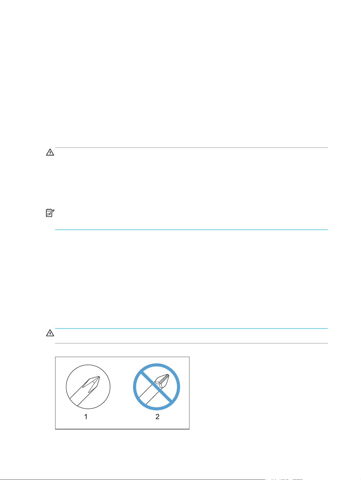
CAUTION: Always use a Phillips screwdriver (callout 1). Do not use a pozidrive screwdriver (callout 2) or any
motorized screwdriver. These can damage screws or screw threads.
Figure 1-1 Screwdrivers
2 Chapter 1 Removal and replacement ENWW

CAUTION: Do not pull directly on the wires to disconnect them. Always pull on the plastic body of a
connector to avoid damaging the connector wires.
Types of screws
WARNING! Make sure that components are replaced with the correct screw type. Using an incorrect screw
(for example, substituting a long screw for the correct shorter screw) can cause damage to the product or
interfere with product operation. Do not intermix screws that are removed from one component with the
screws that are removed from another component.
ENWW Removal and replacement strategy 3

Service approach
Before performing service
WARNING! Turn the product off, wait 5 seconds, and then remove the power cord before attempting to
service the product. If this warning is not followed, severe bodily injury and damage to the device can result.
The power must be on for certain functional checks during troubleshooting. However, the power supply
should be disconnected during parts removal.
●
Remove the toner cartridges. See
●
Remove the imaging drum. See
●
Remove all paper.
●
Remove the dust cover, input tray, and extension tray. See
on page 9.
●
Place the product on an ESD mat (if available).
After performing service
●
Reinstall the dust cover, input tray, and extension tray.
●
Return all paper to the tray.
●
Plug in the power cable and turn on the product.
●
Reinstall the toner cartridges.
●
Reinstall the imaging drum.
Parts removal order
If multiple components must be removed to gain access to an assembly, the first step of the removal
procedure lists all of the components that must be removed to gain access to that assembly. Use these lists
to determine which parts must be removed before removing other parts.
Toner cartridges on page 5.
Imaging drum on page 7.
Dust cover, input tray, and extension tray
4 Chapter 1 Removal and replacement ENWW

Removal and replacement procedures
Customer-replaceable parts
Toner cartridges
1. Lift the scanner assembly.
2. Open the top cover.
3. Remove the toner cartridge.
ENWW Removal and replacement procedures 5
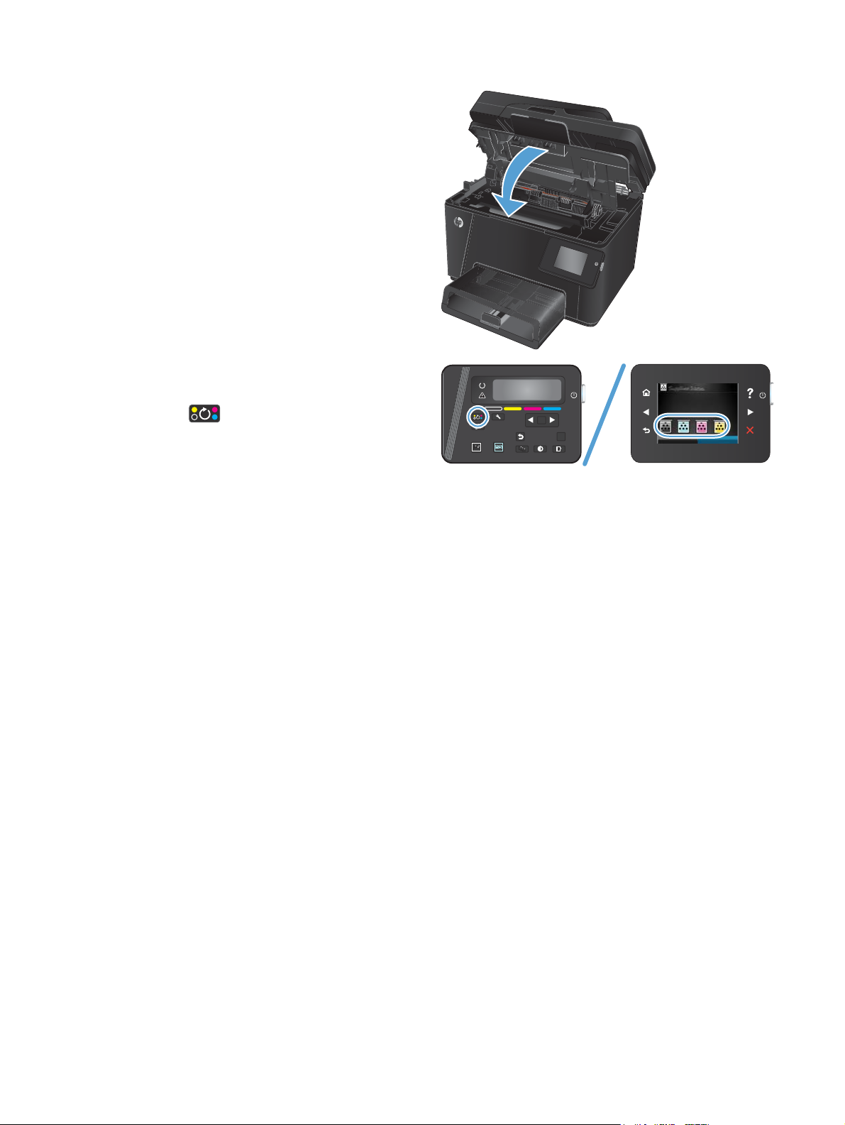
4. Close the top cover.
5. Rotate to the next cartridge to be removed.
●
LCD Control panel: Press the Rotate
Cartridges
button to move to the next
cartridge. Repeat this process until all the
toner cartridges are removed.
●
Touchscreen control panel: Touch the
Supply icon for the cartridge to be removed.
The cartridges rotate to the selected
cartridge. Repeat this process until all the
toner cartridges are removed.
NOTE: The top cover must be closed to rotate
the cartridges.
OK
X
6 Chapter 1 Removal and replacement ENWW

Imaging drum
1. Lift the scanner assembly.
2. Open the top cover.
3. Remove the dust cover from the tray.
ENWW Removal and replacement procedures 7
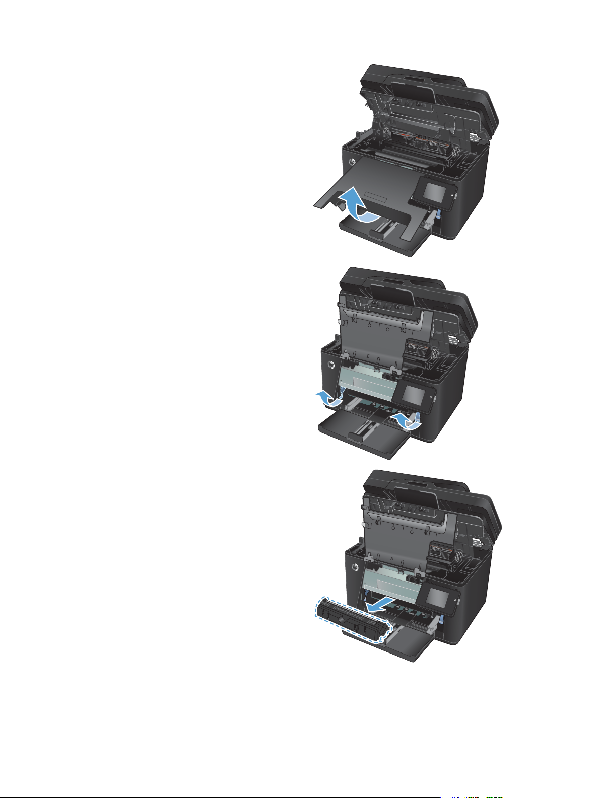
4. Open the front cover.
5. Lift the two levers that hold the imaging drum.
6. Remove the imaging drum.
8 Chapter 1 Removal and replacement ENWW
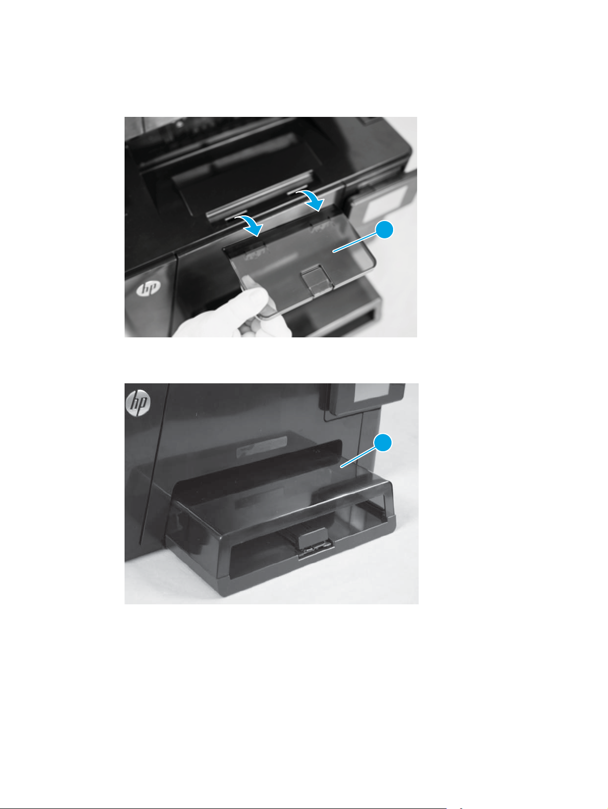
Dust cover, input tray, and extension tray
1. Lift the extension tray (callout 1) away from the product.
Figure 1-2 Remove the extension tray
2. Lift the dust cover (callout 1) away from the product.
1
Figure 1-3 Remove the dust cover
1
ENWW Removal and replacement procedures 9

3. Pull the input tray (callout 1) out from the front of the product and remove it.
Figure 1-4 Remove the input tray
1
Reinstallation tip When reinstalling the input tray, align the tabs on the tray with the slots on the
product.
10 Chapter 1 Removal and replacement ENWW

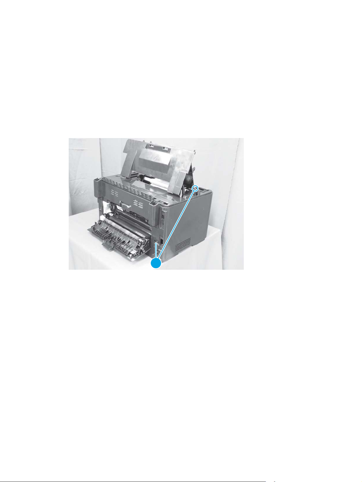
Separation pad assembly
Before proceeding, remove the following components:
●
Dust cover, input tray, and extension tray. See
Remove the separation pad assembly
1. Rotate the product onto the rear side.
WARNING! The ADF portion of the document feeder is not captive and can open when the product is
placed face up. Make sure to support the ADF when handling the product.
NOTE: Dirt and debris can scratch the surface of the product. Make sure to place the product face up
on a clean work space or on a clean soft cloth.
2. Remove two screws (callout 1) and the separation pad assembly (callout 2).
Figure 1-5 Remove the separation pad assembly
2
Dust cover, input tray, and extension tray on page 9.
1
ENWW Removal and replacement procedures 11
Covers and external components
Left cover
1. Open the following doors:
●
Rear door
●
Front door
●
Top door
2. Remove two screws (callout 1).
Figure 1-6 Remove the left cover (1 of 3)
1
12 Chapter 1 Removal and replacement ENWW
 Loading...