

Page 1
LASERJET PRO 100 COLOR MFP M175
Service Manual
Page 2

HP LaserJet Pro 100 color MFP M175
Service Manual
Page 3

Copyright and License
Trademark Credits
© 2011 Copyright Hewlett-Packard
Development Company, L.P.
Reproduction, adaptation, or translation
without prior written permission is
prohibited, except as allowed under the
copyright laws.
The information contained herein is subject
to change without notice.
The only warranties for HP products and
services are set forth in the express warranty
statements accompanying such products and
services. Nothing herein should be
construed as constituting an additional
warranty. HP shall not be liable for technical
or editorial errors or omissions contained
herein.
Part number: CE865-90968
Edition 1, 4/2011
Microsoft®, Windows®, Windows® XP,
and Windows Vista® are U.S. registered
trademarks of Microsoft Corporation.
Page 4

Conventions used in this guide
TIP: Tips provide helpful hints or shortcuts.
NOTE: Notes provide important information to explain a concept or to complete a task.
CAUTION: Cautions indicate procedures that you should follow to avoid losing data or damaging
the product.
WARNING! Warnings alert you to specific procedures that you should follow to avoid personal
injury, catastrophic loss of data, or extensive damage to the product.
ENWW iii
Page 5

Table of contents
1 Removal and replacement ................................................................................................ 1
Introduction ............................................................................................................................. 2
Removal and replacement strategy ............................................................................................. 2
Electrostatic discharge .............................................................................................................. 3
Required tools .......................................................................................................................... 3
Service approach ..................................................................................................................... 4
Before performing service .......................................................................................... 4
After performing service ............................................................................................. 4
Post-service test ......................................................................................................... 4
Product verification test ............................................................................... 4
Parts removal order ................................................................................................... 5
Removal and replacement procedures ........................................................................................ 7
Print cartridges .......................................................................................................... 7
Imaging drum ........................................................................................................... 9
Input tray ............................................................................................................... 11
Secondary transfer roller .......................................................................................... 12
Separation pad assembly ......................................................................................... 13
Pickup roller ........................................................................................................... 14
Remove the pickup roller assembly ............................................................. 15
Covers and document feeder .................................................................................... 16
Right cover .............................................................................................. 16
Left cover ................................................................................................ 17
Document feeder ...................................................................................... 18
Remove the document feeder ...................................................... 18
Document feeder hinges ............................................................................ 21
Remove the document feeder hinges ............................................ 21
Top door, rear-top cover, and delivery cover ............................................... 22
Remove the top door, rear-top cover, and delivery cover ................ 22
Reinstall the top door, rear-top cover, and delivery cover ............... 25
Rear door assembly .................................................................................. 27
Remove the rear door assembly .................................................. 27
Rear-lower cover ...................................................................................... 28
ENWW v
Page 6

Remove the rear-lower cover ....................................................... 28
Control panel .......................................................................................... 29
Remove the control panel ........................................................... 29
Left-front cover ......................................................................................... 31
Remove the left-front cover .......................................................... 31
Front door ............................................................................................... 33
Remove the front door ................................................................ 33
Inner cover .............................................................................................. 35
Remove the inner cover .............................................................. 35
Main assemblies ..................................................................................................... 38
Formatter PCA (base model) ...................................................................... 38
Remove the formatter PCA (base model) ....................................... 38
Formatter and wireless PCA (plus model) ..................................................... 40
Remove the formatter and wireless PCA (plus model) ..................... 40
Fuser power supply .................................................................................. 42
Remove the fuser power supply ................................................... 42
ITB assembly ............................................................................................ 43
Remove the ITB assembly ............................................................ 43
Fuser delivery assembly ............................................................................ 53
Remove the fuser delivery assembly ............................................. 54
Engine controller assembly ........................................................................ 58
Remove the engine controller assembly ........................................ 58
Low-voltage power supply assembly ........................................................... 63
Remove the low-voltage power supply assembly ............................ 63
Document feeder components ................................................................................... 69
Document feeder input tray ........................................................................ 69
Document feeder cover ............................................................................. 70
Document feeder core ............................................................................... 72
Remove the document feeder core ............................................... 72
Post scan pinch rollers .............................................................................. 74
Remove the post scan pinch rollers .............................................. 74
Document feeder base assembly ................................................................ 75
Remove the document feeder base assembly ................................ 75
2 Solve problems ............................................................................................................... 77
Solve problems checklist ......................................................................................................... 78
Step 1: Test print functionality ................................................................................... 78
Step 2: Test copy functionality .................................................................................. 78
Menu map ............................................................................................................................ 79
Troubleshooting processes ....................................................................................................... 80
Determine the problem source ................................................................................... 80
vi ENWW
Page 7

Power subsystem ..................................................................................................... 81
Power-on checks ...................................................................................... 81
Tools for troubleshooting ......................................................................................................... 82
Component diagnostics ............................................................................................ 82
Component tests ....................................................................................... 82
Control-panel tests ..................................................................... 82
Diagrams ............................................................................................................... 83
Locations of connectors ............................................................................. 83
Locations of major components .................................................................. 84
General timing chart ................................................................................. 86
General circuit diagram ............................................................................ 87
Internal print-quality test pages .................................................................................. 88
Print a Diagnostics Page ........................................................................... 88
Interpret the Print Quality Page ................................................................... 89
Print-quality troubleshooting tools .............................................................................. 90
Repetitive image defects ruler .................................................................... 90
Calibrate the product ................................................................................ 90
Control panel menus ................................................................................................ 91
Setup menu ............................................................................................. 91
Reports menu ............................................................................ 91
System Setup menu .................................................................... 91
Service menu ............................................................................ 94
Network Setup menu (network models only) ................................. 94
Function specific menus ............................................................................. 95
Copy Menu .............................................................................. 95
Service mode functions ........................................................................................................... 97
Service menu/Secondary service menu ...................................................................... 97
Service menu ........................................................................................... 97
Secondary service menu ........................................................................... 97
Open the secondary service menu ............................................... 97
Secondary service menu structure ................................................ 98
Product resets ......................................................................................................... 99
Restore factory settings .............................................................................. 99
NVRAM initialization ................................................................................ 99
Product updates ..................................................................................................................... 99
3 Parts and diagrams ...................................................................................................... 101
Order parts by authorized service providers ............................................................................ 102
Order replacement parts ........................................................................................ 102
Related documentation and software ....................................................................... 102
Supplies part numbers ........................................................................................... 102
ENWW vii
Page 8

Service parts ........................................................................................................ 103
Whole-unit replacement part numbers ...................................................................... 103
How to use the parts lists and diagrams .................................................................................. 104
Assembly locations ............................................................................................................... 105
Base product (no optional trays or accessories) ......................................................... 105
Covers, panels, and doors .................................................................................................... 106
Internal assembly ................................................................................................................. 108
Internal assembly .................................................................................................. 108
PCAs .................................................................................................................................. 110
Scanner and document feeder (ADF) main assemblies .............................................................. 112
Document feeder internal components .................................................................................... 114
Alphabetical parts list ........................................................................................................... 116
Numerical parts list .............................................................................................................. 119
Appendix A Service and support ..................................................................................... 123
Hewlett-Packard limited warranty statement ............................................................................. 124
HP's Premium Protection Warranty: LaserJet print cartridge limited warranty statement .................. 126
HP's LaserJet imaging drum limited warranty statement for replacement imaging drums ................ 127
Data stored on the print cartridge and imaging drum ............................................................... 128
End User License Agreement .................................................................................................. 129
OpenSSL ............................................................................................................................. 131
Customer self-repair warranty service ..................................................................................... 132
Customer support ................................................................................................................. 132
Repack the product .............................................................................................................. 133
Appendix B Specifications ................................................................................................ 135
Physical specifications .......................................................................................................... 136
Power consumption, electrical specifications, and acoustic emissions .......................................... 136
Environmental specifications .................................................................................................. 136
Appendix C Regulatory information ................................................................................. 137
FCC regulations ................................................................................................................... 138
Declaration of conformity (base models) ................................................................................. 139
Declaration of conformity (wireless models) ............................................................................. 141
Certificate of Volatility .......................................................................................................... 143
Safety statements ................................................................................................................. 144
Laser safety .......................................................................................................... 144
Canadian DOC regulations .................................................................................... 144
VCCI statement (Japan) .......................................................................................... 144
Power cord instructions .......................................................................................... 144
viii ENWW
Page 9

Power cord statement (Japan) ................................................................................. 144
EMC statement (Korea) .......................................................................................... 145
Laser statement for Finland ..................................................................................... 145
GS statement (Germany) ........................................................................................ 145
Substances Table (China) ....................................................................................... 146
Restriction on Hazardous Substances statement (Turkey) ............................................. 146
Additional statements for wireless products .............................................................................. 147
FCC compliance statement—United States ................................................................ 147
Australia statement ................................................................................................ 147
Brazil ANATEL statement ........................................................................................ 147
Canadian statements ............................................................................................. 147
European Union regulatory notice ........................................................................... 147
Notice for use in France ......................................................................................... 148
Notice for use in Russia ......................................................................................... 148
Korean statement .................................................................................................. 148
Taiwan statement .................................................................................................. 148
Index ............................................................................................................................... 149
ENWW ix
Page 10

List of tables
Table 2-1 External covers and doors (base) ............................................................................................ 85
Table 2-2 Service menu ..................................................................................................................... 97
Table 2-3 Secondary service menu ........................................................................................................ 98
Table 3-1 Order parts, accessories, and supplies .................................................................................. 102
Table 3-2 Related documentation and software .................................................................................... 102
Table 3-3 Supplies part numbers ......................................................................................................... 102
Table 3-4 Whole-unit replacement part numbers ................................................................................... 103
Table 3-5 Base product ..................................................................................................................... 105
Table 3-6 Covers, panels, and doors ................................................................................................... 107
Table 3-7 Internal assembly) ............................................................................................................... 109
Table 3-8 PCAs ................................................................................................................................ 111
Table 3-9 Scanner and document feeder main assemblies ..................................................................... 113
Table 3-10 Document feeder assembly parts ........................................................................................ 115
Table 3-11 Alphabetical parts list ....................................................................................................... 116
Table 3-12 Numerical parts list ........................................................................................................... 119
Table B-1 Physical specifications
Table B-2 Environmental specifications ................................................................................................ 136
1
........................................................................................................ 136
ENWW xi
Page 11

List of figures
Figure 1-1 Phillips and Pozidriv screwdriver comparison ............................................................................ 3
Figure 1-2 Parts removal order (base) ...................................................................................................... 5
Figure 1-3 Parts removal order (document feeder) ..................................................................................... 6
Figure 1-4 Remove the tray .................................................................................................................. 11
Figure 1-5 Remove the secondary transfer roller ...................................................................................... 12
Figure 1-6 Remove the separation pad assembly (1 of 1) ......................................................................... 13
Figure 1-7 Remove the pickup roller assembly (1 of 2) ............................................................................. 15
Figure 1-8 Remove the pickup roller assembly (2 of 2) ............................................................................. 15
Figure 1-9 Remove the right cover (1 of 2) ............................................................................................. 16
Figure 1-10 Remove the right cover (2 of 2) ........................................................................................... 16
Figure 1-11 Remove the left cover (1 of 2) ............................................................................................. 17
Figure 1-12 Remove the left cover (2 of 2) ............................................................................................. 17
Figure 1-13 Remove the document feeder (1 of 4) ................................................................................... 18
Figure 1-14 Remove the document feeder (2 of 4) ................................................................................... 19
Figure 1-15 Remove the document feeder (3 of 4) ................................................................................... 19
Figure 1-16 Remove the document feeder (4 of 4) ................................................................................... 20
Figure 1-17 Remove the scanner hinges (1 of 2) ..................................................................................... 21
Figure 1-18 Remove the scanner hinges (2 of 2) ..................................................................................... 21
Figure 1-19 Remove the top door, rear-top cover, and delivery cover (1 of 6) ............................................ 22
Figure 1-20 Remove the top door, rear-top cover, and delivery cover (2 of 6) ............................................ 23
Figure 1-21 Remove the top door, rear-top cover, and delivery cover (3 of 6) ............................................ 23
Figure 1-22 Remove the top door, rear-top cover, and delivery cover (4 of 6) ............................................ 24
Figure 1-23 Remove the top door, rear-top cover, and delivery cover (5 of 6) ............................................ 24
Figure 1-24 Remove the top door, rear-top cover, and delivery cover (6 of 6) ............................................ 25
Figure 1-25 Reinstall the top door, rear-top cover, and delivery cover (1 of 2) ............................................ 25
Figure 1-26 Reinstall the top door, rear-top cover, and delivery cover (1 of 2) ............................................ 26
Figure 1-27 Remove the rear door assembly (1 of 2) ............................................................................... 27
Figure 1-28 Remove the rear door assembly (2 of 2) ............................................................................... 27
Figure 1-29 Remove the rear-lower cover ............................................................................................... 28
Figure 1-30 Remove the control panel (1 of 3) ........................................................................................ 29
Figure 1-31 Remove the control panel (2 of 3) ......
Figure 1-32 Remove the control panel (3 of 3) ........................................................................................ 30
.................................................................................. 30
ENWW xiii
Page 12

Figure 1-33 Remove the left-front cover (1 of 2) ...................................................................................... 31
Figure 1-34 Remove the left-front cover (2 of 2) ...................................................................................... 32
Figure 1-35 Remove the front door (1 of 2) ............................................................................................ 33
Figure 1-36 Remove the front door (2 of 3) ............................................................................................ 34
Figure 1-37 Remove the inner cover (1 of 4) .......................................................................................... 35
Figure 1-38 Remove the inner cover (2 of 4) .......................................................................................... 36
Figure 1-39 Remove the inner cover (3 of 4) .......................................................................................... 36
Figure 1-40 Remove the inner cover (4 of 4) .......................................................................................... 37
Figure 1-41 Remove the formatter PCA (base model; 1 of 2) .................................................................... 38
Figure 1-42 Remove the formatter PCA (base model; 2 of 2) .................................................................... 39
Figure 1-43 Remove the formatter and wireless PCA (plus model; 1 of 3) ................................................... 40
Figure 1-44 Remove the formatter and wireless PCA (plus mode; 2 of 3) ................................................... 40
Figure 1-45 Remove the formatter and wireless PCA (plus mode; 3 of 3) ................................................... 41
Figure 1-46 Remove the fuser power supply (1 of 2) ............................................................................... 42
Figure 1-47 Remove the fuser power supply (2 of 2) ............................................................................... 42
Figure 1-48 Remove the ITB assembly (1 of 17) ...................................................................................... 43
Figure 1-49 Remove the ITB assembly (2 of 17) ...................................................................................... 44
Figure 1-50 Remove the ITB assembly (3 of 17) ...................................................................................... 44
Figure 1-51 Remove the ITB assembly (4 of 17) ...................................................................................... 45
Figure 1-52 Remove the ITB assembly (5 of 17) ...................................................................................... 45
Figure 1-53 Remove the ITB assembly (6 of 17) ...................................................................................... 46
Figure 1-54 Remove the ITB assembly (7 of 17) ...................................................................................... 46
Figure 1-55 Remove the ITB assembly (8 of 17) ...................................................................................... 47
Figure 1-56 Remove the ITB assembly (9 of 17) ...................................................................................... 48
Figure 1-57 Remove the ITB assembly (10 of 17) .................................................................................... 48
Figure 1-58 Remove the ITB assembly (11 of 17) .................................................................................... 49
Figure 1-59 Remove the ITB assembly (12 of 17) .................................................................................... 49
Figure 1-60 Remove the ITB assembly (13 of 17) .................................................................................... 50
Figure 1-61 Remove the ITB assembly (14 of 17) .................................................................................... 50
Figure 1-62 Remove the ITB assembly (15 of 17) .................................................................................... 51
Figure 1-63 Remove the ITB assembly (16 of 17) .................................................................................... 51
Figure 1-64 Remove the ITB assembly (17 of 17) .................................................................................... 52
Figure 1-65 Remove the fuser delivery assembly (1 of 6) .......................................................................... 54
Figure 1-66 Remove the fuse
Figure 1-67 Remove the fuser delivery assembly (3 of 6) .......................................................................... 55
Figure 1-68 Remove the fuser delivery assembly (4 of 6) .......................................................................... 55
Figure 1-69 Remove the fuser delivery assembly (5 of 6) .......................................................................... 56
Figure 1-70 Remove the fuser delivery assembly (6 of 6) .......................................................................... 56
Figure 1-71 Reinstall the fuser delivery assembly (1 of 2) ......................................................................... 57
Figure 1-72 Reinstall the fuser delivery assembly (2 of 2) ......................................................................... 57
Figure 1-73 Remove the engine controller assembly (1 of 7) ..................................................................... 58
r delivery assembly (2 of 6) .......................................................................... 54
xiv ENWW
Page 13

Figure 1-74 Remove the engine controller assembly (2 of 7) ..................................................................... 59
Figure 1-75 Remove the engine controller assembly (3 of 7) ..................................................................... 59
Figure 1-76 Remove the engine controller assembly (4 of 7) ..................................................................... 60
Figure 1-77 Remove the engine controller assembly (5 of 7) ..................................................................... 60
Figure 1-78 Remove the engine controller assembly (6 of 7) ..................................................................... 61
Figure 1-79 Remove the engine controller assembly (7 of 7) ..................................................................... 61
Figure 1-80 Installing a replacement engine controller assembly ............................................................... 62
Figure 1-81 Remove the low-voltage power supply assembly (1 of 9) ........................................................ 63
Figure 1-82 Remove the low-voltage power supply assembly (2 of 9) ........................................................ 64
Figure 1-83 Remove the low-voltage power supply assembly (3 of 9) ........................................................ 64
Figure 1-84 Remove the low-voltage power supply assembly (4 of 9) ........................................................ 65
Figure 1-85 Remove the low-voltage power supply assembly (5 of 9) ........................................................ 65
Figure 1-86 Remove the low-voltage power supply assembly (6 of 9) ........................................................ 66
Figure 1-87 Remove the low voltage power supply assembly (7 of 9) ........................................................ 66
Figure 1-88 Remove the low-voltage power supply assembly (8 of 9) ........................................................ 67
Figure 1-89 Remove the low-voltage power supply assembly (9 of 9) ........................................................ 67
Figure 1-90 Reinstall the low-voltage power supply ................................................................................. 68
Figure 1-91 Installing a replacement low-voltage power supply ................................................................ 68
Figure 1-92 Remove the document feeder input tray (1 of 2) .................................................................... 69
Figure 1-93 Remove the document feeder input tray (2 of 2) .................................................................... 69
Figure 1-94 Remove the document feeder cover (1 of 3) .......................................................................... 70
Figure 1-95 Remove the document feeder cover (2 of 3) .......................................................................... 70
Figure 1-96 Remove the document feeder cover (3 of 3) .......................................................................... 71
Figure 1-97 Remove the document feeder core (1 of 4) ........................................................................... 72
Figure 1-98 Remove the document feeder core (2 of 4) ........................................................................... 72
Figure 1-99 Remove the document feeder core (3 of 4) ........................................................................... 73
Figure 1-100 Remove the document feeder core (4 of 4) ......................................................................... 73
Figure 1-101 Remove the post scan pinch rollers .................................................................................... 74
Figure 1-102 Remove the document feeder base assembly (1 of 3) ........................................................... 75
Figure 1-103 Remove the document feeder base assembly (2 of 3) ........................................................... 76
Figure 1-104 Remove the document feeder base assembly (3 of 3) ........................................................... 76
Figure 2-
Figure 2-2 Cross section view ............................................................................................................... 84
Figure 2-3 External covers and doors (base) ........................................................................................... 85
Figure 2-4 General timing diagram ....................................................................................................... 86
Figure 2-5 General circuit diagram ....................................................................................................... 87
Figure 2-6 Diagnostics Page ................................................................................................................. 88
Figure 3-1 Base product (no optional trays or accessories) ..................................................................... 105
Figure 3-2 Covers, panels, and doors ................................................................................................. 106
Figure 3-3 Internal assembly ............................................................................................................... 108
Figure 3-4 PCAs ............................................................................................................................... 110
1 Locations of connectors ........................................................................................................ 83
ENWW xv
Page 14

Figure 3-5 Scanner and document feeder main assemblies .................................................................... 112
Figure 3-6 Document feeder assembly parts ......................................................................................... 114
xvi ENWW
Page 15

1 Removal and replacement
Introduction
●
Removal and replacement strategy
●
Electrostatic discharge
●
Required tools
●
Service approach
●
Removal and replacement procedures
●
ENWW 1
Page 16

Introduction
This chapter describes the removal and replacement of field-replaceable units (FRUs) only.
Replacing FRUs is generally the reverse of removal. Occasionally, notes and tips are included to
provide directions for difficult or critical replacement procedures.
HP does not support repairing individual subassemblies or troubleshooting to the component level.
Note the length, diameter, color, type, and location of each screw. Be sure to return each screw to its
original location during reassembly.
Incorrectly routed or loose wire harnesses can interfere with other internal components and can become
damaged or broken. Frayed or pinched harness wires can be difficult to find. When replacing wire
harnesses, always use the provided wire loops, lance points, or wire-harness guides and retainers.
Removal and replacement strategy
WARNING! Turn the product off, wait 5 seconds, and then remove the power cord before
attempting to service the product. If this warning is not followed, severe injury can result, in addition to
damage to the product. The power must be on for certain functional checks during troubleshooting.
However, disconnect the power supply during parts removal.
Never operate or service the product with the protective cover removed from the laser/scanner
assembly. The reflected beam, although invisible, can damage your eyes.
The sheet-metal parts can have sharp edges. Be careful when handling sheet-metal parts.
CAUTION: Do not bend or fold the flat flexible cables (FFCs) during removal or installation. Also, do
not straighten pre-folds in the FFCs. You must fully seat all FFCs in their connectors. Failure to fully seat
an FFC into a connector can cause a short circuit in a PCA.
NOTE: To install a self-tapping screw, first turn it counterclockwise to align it with the existing thread
pattern, and then carefully turn it clockwise to tighten. Do not overtighten. If a self-tapping screw-hole
becomes stripped, repair the screw-hole or replace the affected assembly.
TIP: For clarity, some photos in this chapter show components removed that would not be removed to
service the product. If necessary, remove the components listed at the beginning of a procedure before
proceeding to service the product.
2 Chapter 1 Removal and replacement ENWW
Page 17
Electrostatic discharge
CAUTION: Some parts are sensitive to electrostatic discharge (ESD). Look for the ESD reminder
when removing product parts. Always perform service work at an ESD-protected workstation or mat, or
use an ESD strap. If an ESD workstation, mat, or strap is not available, ground yourself by touching the
sheet-metal chassis before touching an ESD-sensitive part.
Protect the ESD-sensitive parts by placing them in ESD pouches when they are out of the product.
Required tools
#2 Phillips screwdriver with a magnetic tip and a 152-mm (6-inch) shaft length
●
Small flat-blade screwdriver
●
Needle-nose pliers
●
ESD mat (if one is available) or ESD strap
●
Penlight (optional)
●
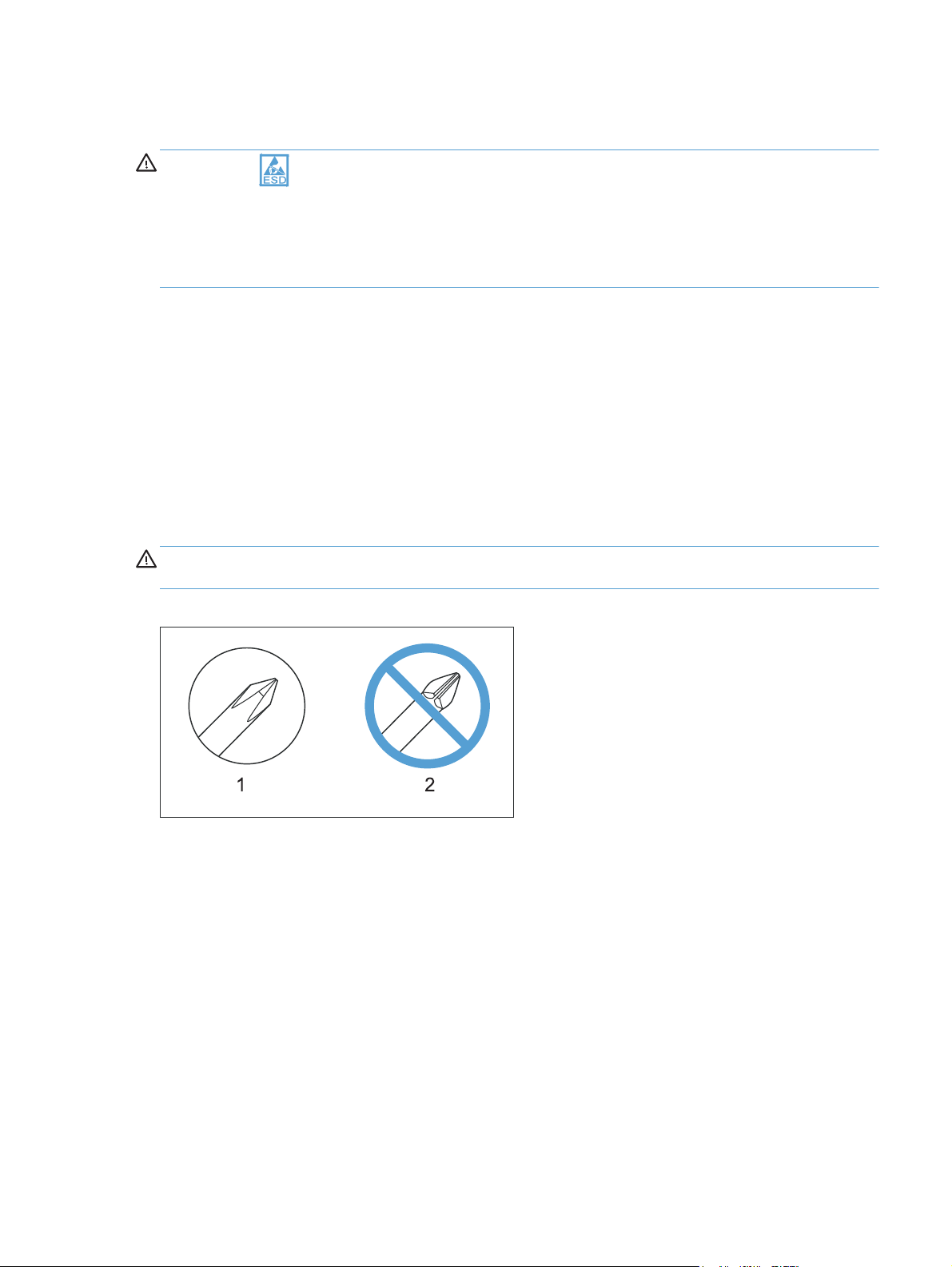
CAUTION: Always use a Phillips screwdriver (callout 1). Do not use a Pozidriv screwdriver
(callout 2) or any motorized screwdriver. These can damage screws or screw threads.
Figure 1-1 Phillips and Pozidriv screwdriver comparison
ENWW
Electrostatic discharge
3
Page 18

Service approach
Before performing service
Remove all paper from the product.
●
Turn off the power using the power button.
●
WARNING! The power button must be turned off before performing service. Failure to turn off
the power leaves the fuser engaged and prevents its removal.
Unplug the power cable and interface cable or cables.
●
Place the product on an ESD workstation or mat (if one is available), or use an ESD strap. If an
●
ESD workstation, mat, or strap is not available, ground yourself by touching the sheet-metal
chassis before touching an ESD-sensitive part.
Remove the print cartridges and imaging drum. See
●
drum on page 9
Remove the input tray. See
●
After performing service
Plug in the power cable.
●
Reinstall the print cartridges.
●
Load paper in the product.
●
Post-service test
Perform the following test to verify that the repair or replacement was successful.
Product verification test
1. Verify that you have completed the necessary reassembly steps.
2. Make sure that the tray contains clean, unmarked paper.
3. Attach the power cord and interface cable or interface cables, and then turn on the product.
Print cartridges on page 7 and Imaging
Input tray on page 11.
4. Verify that the expected startup sounds occur.
5. Print a configuration page, and then verify that the expected printing sounds occur.
6. Send a print job from the host computer, and then verify that the output meets expectations.
7. Use the document feeder to make a copy.
8. Clean the outside of the product with a damp cloth.
4 Chapter 1 Removal and replacement ENWW
Page 19

Parts removal order
Figure 1-2 Parts removal order (base)
Print cartridges
Imaging drum
Input tray
Secondary
transfer roller
Separation pad
Pickup roller
Right cover assembly
Left cover assembly
Document feeder
Document feeder
hinges
Separation
pad
Left cover
Left cover
Right cover
Document
feeder
Left cover
Top door, rear cover,
and delivery cover
Rear door assembly
Rear-lower cover
Control Panel
Left-front cover
Front door
Inner cover
Formatter PCA
(base model)
Formatter and
wireless PCA
(plus model)
Fuser power supply
ITB
Fuser delivery
assembly
Engine controller
assembly
Low-voltage power
supply assembly
Right cover
Right cover
Right cover
Right cover
Right cover
Right cover
Right cover
Left cover
Left cover
Left cover
Right cover
Right cover
Right cover
Right cover
Left cover
Left cover
Left cover
Left cover
Left cover
Left cover
Left cover
Left cover
Left cover
Left cover
Document
feeder
Rear door
Document
feeder
Document
feeder
Document
feeder
Document
feeder
Document
feeder
Document
feeder
Document
feeder
Document
feeder
Document
feeder hinges
Document
feeder hinges
Document
feeder hinges
Document
feeder hinges
Document
feeder hinges
Document
feederhinges
Document
feeder hinges
Document
feeder hinges
Document
feeder hinges
Top door,
rear cover,
and delivery cover
Top door,
rear cover,
and delivery cover
Top door,
rear cover,
and delivery cover
Top door,
rear cover,
and delivery cover
Top door,
rear cover,
livery cover
and de
Top door,
rear cover,
and delivery cover
Top door,
rear cover,
and delivery cover
Top door,
rear cover,
and delivery cover
Control
Pan el
Control
Pan el
Control
Pan el
Rear door
assembly
Rear door
assembly
Control
Pan el
Rear door
assembly
Left-front
cover
Left-front
cover
Rear-lower
cover
Rear-lower
cover
Left-front
cover
Rear-lower
cover
Formatter
PCA
Formatter
PCA
Inner
cover
Control
Pan el
Formatter
PCA
Left-front
cover
Inner cover
Formatter
PCA
ENWW
Service approach
5
Page 20

Figure 1-3 Parts removal order (document feeder)
Document feeder input tray
Document feeder cover
Document core
Post scan pinch rollers
Document feeder input tray
Document feeder cover
Document core
Document feeder base assembly
Document feeder input tray
Document feeder cover
6 Chapter 1 Removal and replacement ENWW
Page 21
Removal and replacement procedures
Print cartridges
When a print cartridge approaches the estimated end of its useful life, you can continue printing with
the current print cartridge until it no longer yields acceptable print quality.
Once an HP print cartridge has reached “very low’, the HP Premium Protection Warranty on that
supply has ended. All print defects or print cartridge failures incurred when an HP supply is used in
continue at very low mode will not be considered to be defects in materials or workmanship in the
supply under the HP Print Cartridge Warranty Statement.
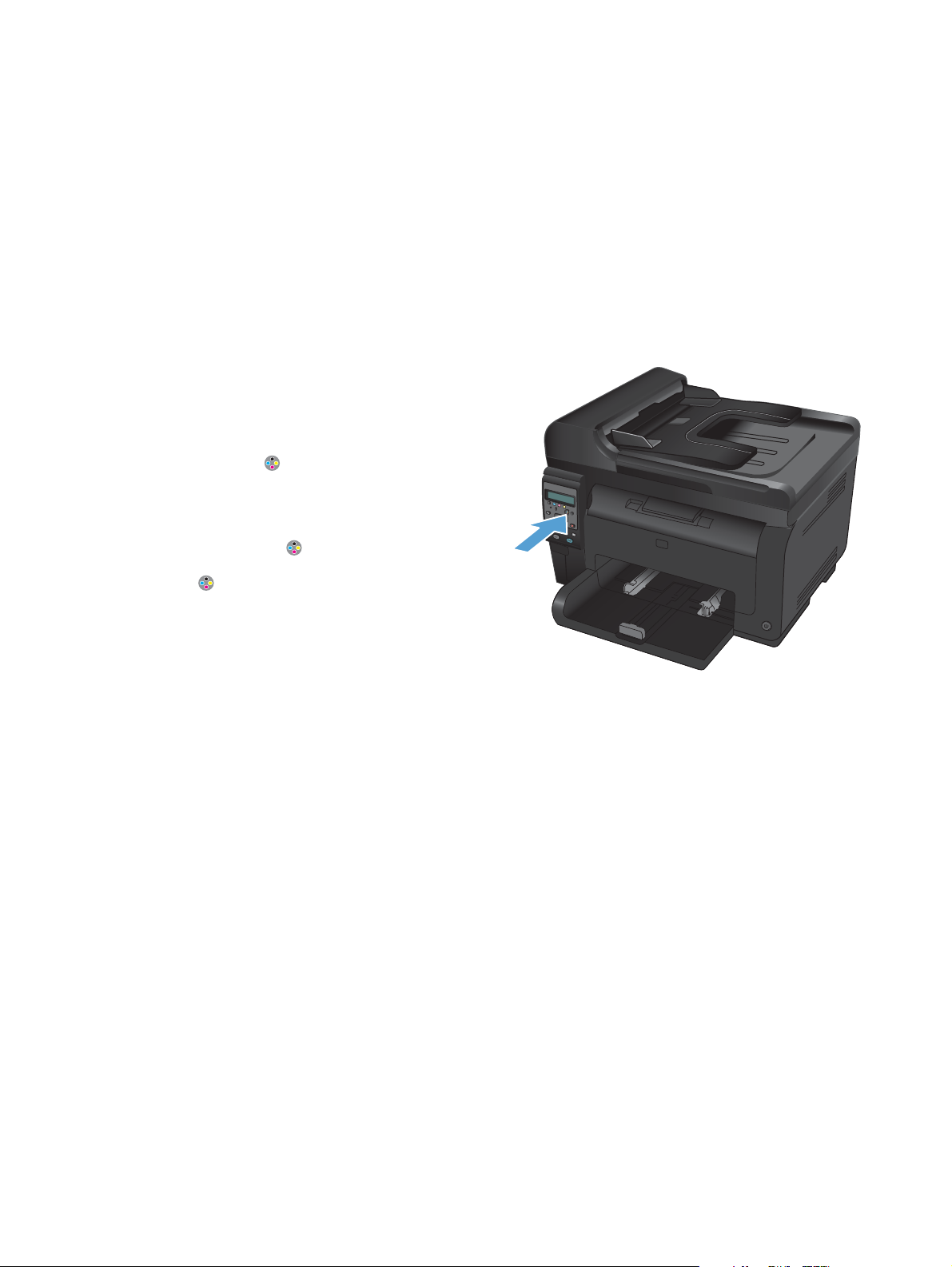
1. Some error messages or status messages cause
the product to rotate the print cartridge
carousel to the affected cartridge
automatically. If the print cartridge that needs
to be replaced is not in the correct position,
press the Cartridge
cartridge carousel to the cartridge color that
you want to replace.
NOTE: All doors must be closed when
pressing the Cartridge
imaging drum must be installed for the
Cartridge
NOTE: Wait until the Rotating message
and the rotation sounds stop before opening
the print cartridge door.
button to work.
button to rotate the print
button. Also, the
ENWW
Removal and replacement procedures
7
Page 22
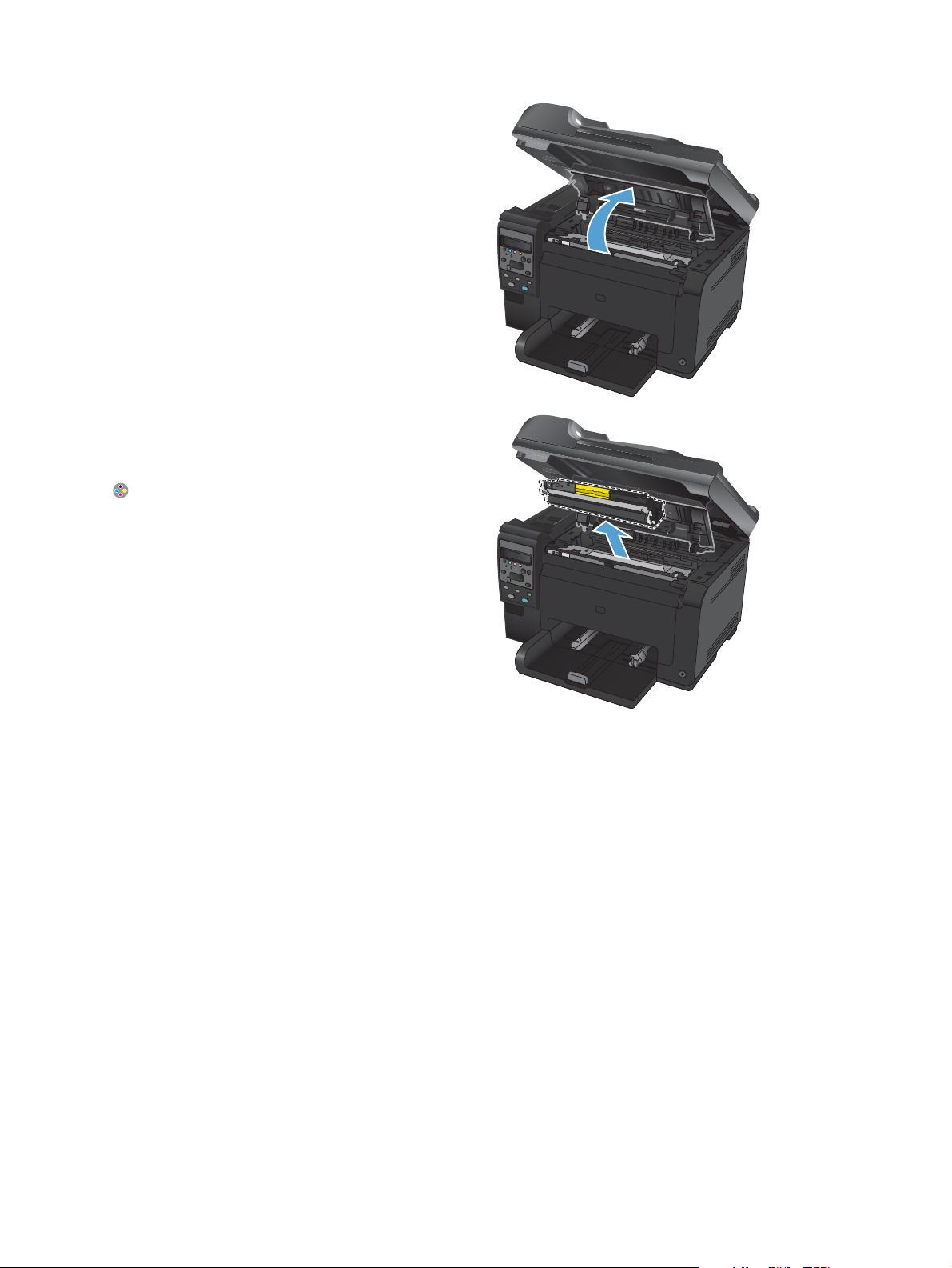
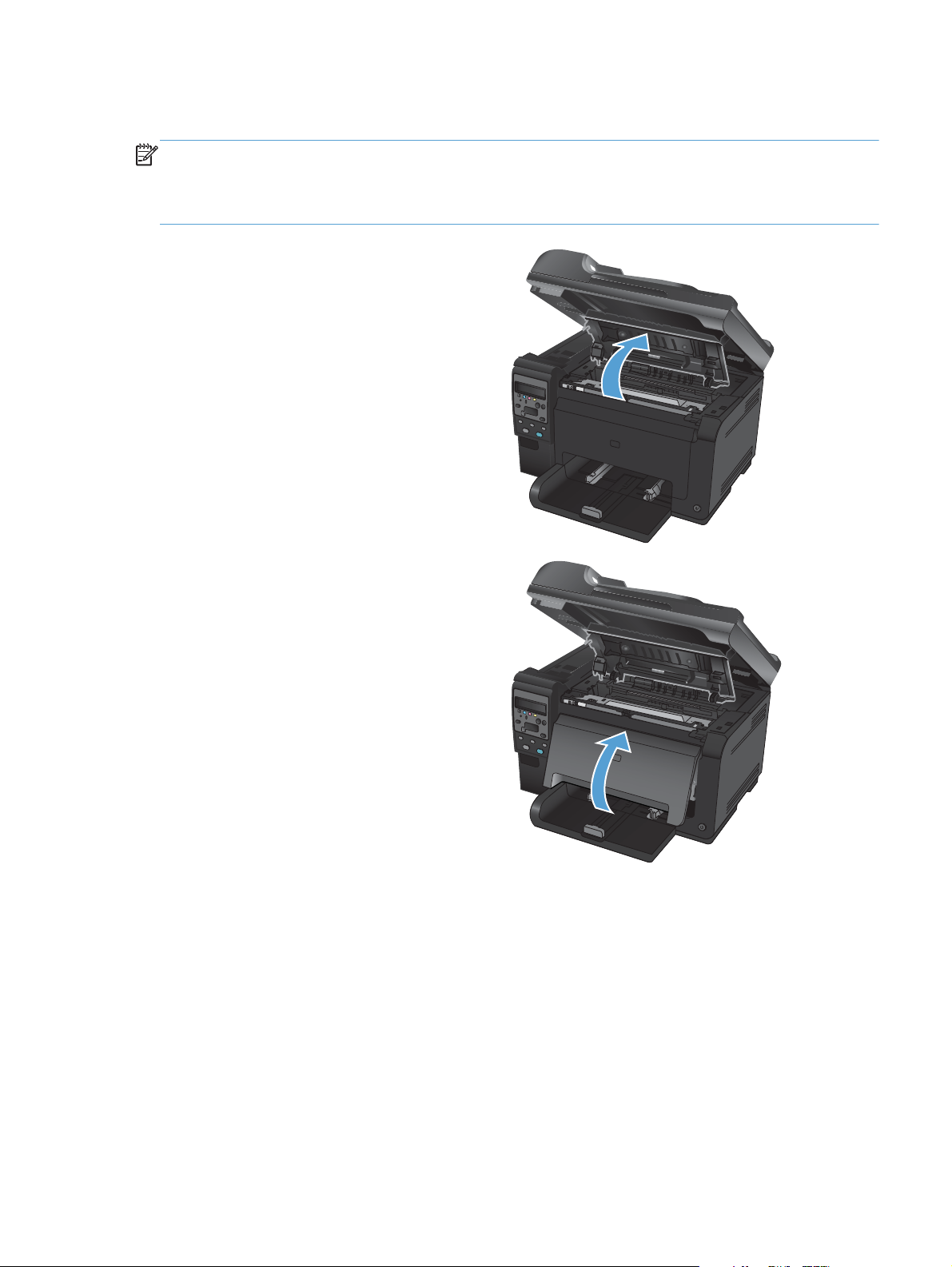
2. Open the print cartridge door.
3. Grasp the old print cartridge by the center
handle and remove it.
Close the doors, and then press the Cartridge
button to rotate the print cartridge carousel
to the next cartridge. Repeat to remove all
cartridges.
NOTE: Make sure that you store the
removed print cartridges away from strong
light. HP recommends that you cover the print
cartridges while servicing the product.
8 Chapter 1 Removal and replacement ENWW
Page 23
Imaging drum
NOTE: The imaging drum installed in this product is covered by the product warranty. Replacement
imaging drums have a one-year limited warranty from the date of installation. The imaging drum
installation date displays on the supplies status page. The HP Premium Protection Warranty applies only
to the print cartridges for the product.
1. Open the print cartridge door.
2. Open the front cover.
ENWW
Removal and replacement procedures
9
Page 24
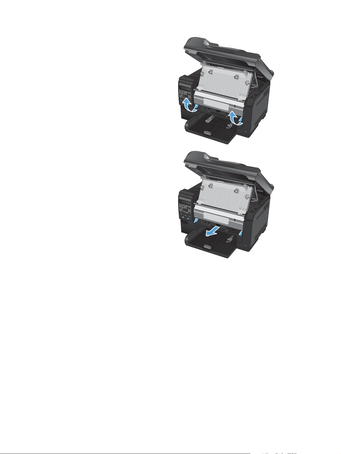
3. Lift the two levers that hold the imaging drum.
4. Remove the old imaging drum.
NOTE: Make sure that you store the
removed imaging drum away from strong
light. HP recommends that you cover the
imaging drum while servicing the product.
10 Chapter 1 Removal and replacement ENWW
Page 25
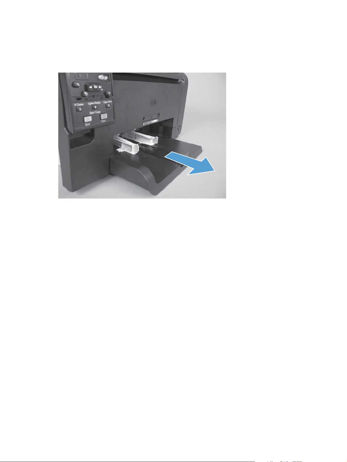
Input tray
Pull the tray away from the printer to remove.
Figure 1-4 Remove the tray
ENWW
Removal and replacement procedures
11
Page 26
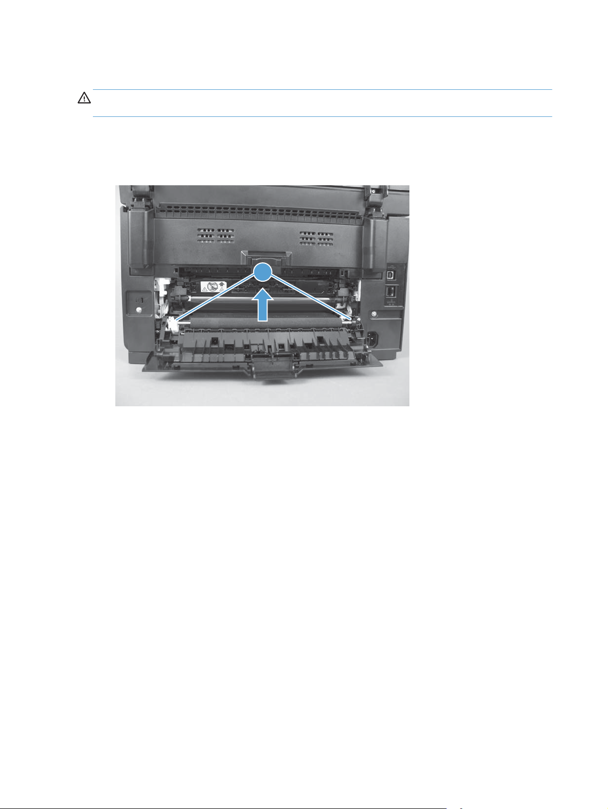
Secondary transfer roller
CAUTION: Do not touch the black spongy part of the roller. Skin oils might cause print-quality
problems.
1. Open the rear door.
2. Release two clips (callout 1), and then remove the roller from the product.
Figure 1-5 Remove the secondary transfer roller
1
12 Chapter 1 Removal and replacement ENWW
Page 27
Separation pad assembly
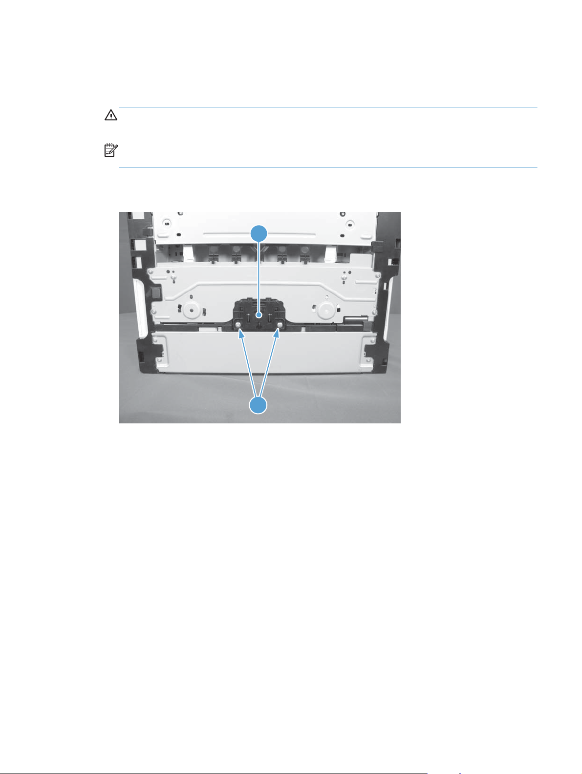
1. Turn the product face up.
WARNING! The ADF portion of the document feeder is not captive and can open when the
product is placed face up. Make sure that you support the ADF when handling the product.
NOTE: Dirt and debris can scratch the surface of the product. Make sure that you place the
product face up on a clean work space or on a clean soft cloth.
2. Remove two screws (callout 1) and the separation pad assembly (callout 2).
Figure 1-6 Remove the separation pad assembly (1 of 1)
2
1
ENWW
Removal and replacement procedures
13
Page 28

Pickup roller
Before proceeding, remove the following components:
Separation pad assembly. See
●
Right cover assembly. See
●
Left cover assembly. See
●
Rotate the pickup roller to the service position
To gain access to the roller locking tabs you must rotate the roller to the correct position for removal.
1. When the product is in the Ready state, press and hold the Auto-On/Auto-Off (power) button for
about seven seconds or until the Ready light turns off.
TIP: Optionally, unplug the power cord, and then plug the cord back in.
2. Make sure that one sheet of paper is loaded in the input tray.
NOTE: If more than one sheet of paper is loaded in the tray, this procedure will not be
successful.
3. Press and release the Auto-On/Auto-Off (power) button and within two seconds press and hold
down the cyan cartridge button. Hold the cyan button down for about five seconds, or until the
initialization process begins.
NOTE: Immediately after the Auto-On/Auto-Off (power) button is pressed, all of the control
panel lights illuminate briefly (for about two seconds). You must press the cyan cartridge button
while the lights are illuminated.
Separation pad assembly on page 13.
Right cover on page 16.
Left cover on page 17.
4. When the product finishes initializing, the roller rotates into the removal position. Turn the product
off. Unplug the product before removing any components.
NOTE: When the roller is in the removal position, the sheet of paper will have been pulled into
the paper path by about 12 mm (.5 in). This is visual confirmation that the roller has rotated to the
removal position.
14 Chapter 1 Removal and replacement ENWW
Page 29
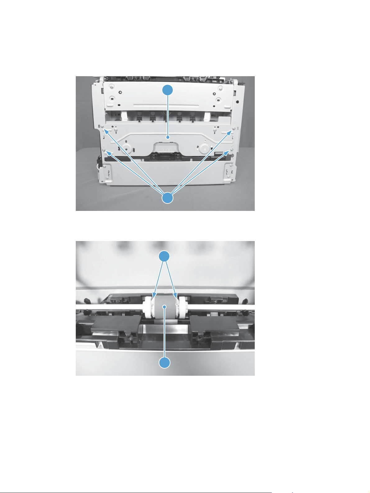
Remove the pickup roller assembly
1. Remove four screws (callout 1) and the lower stay part (callout 2).
Figure 1-7 Remove the pickup roller assembly (1 of 2)
2
1
2. Release two tabs (callout 1) and remove the pickup roller (callout 2).
Figure 1-8 Remove the pickup roller assembly (2 of 2)
1
2
ENWW
Removal and replacement procedures
15
Page 30
Covers and document feeder
Right cover
1. Open the document feeder.
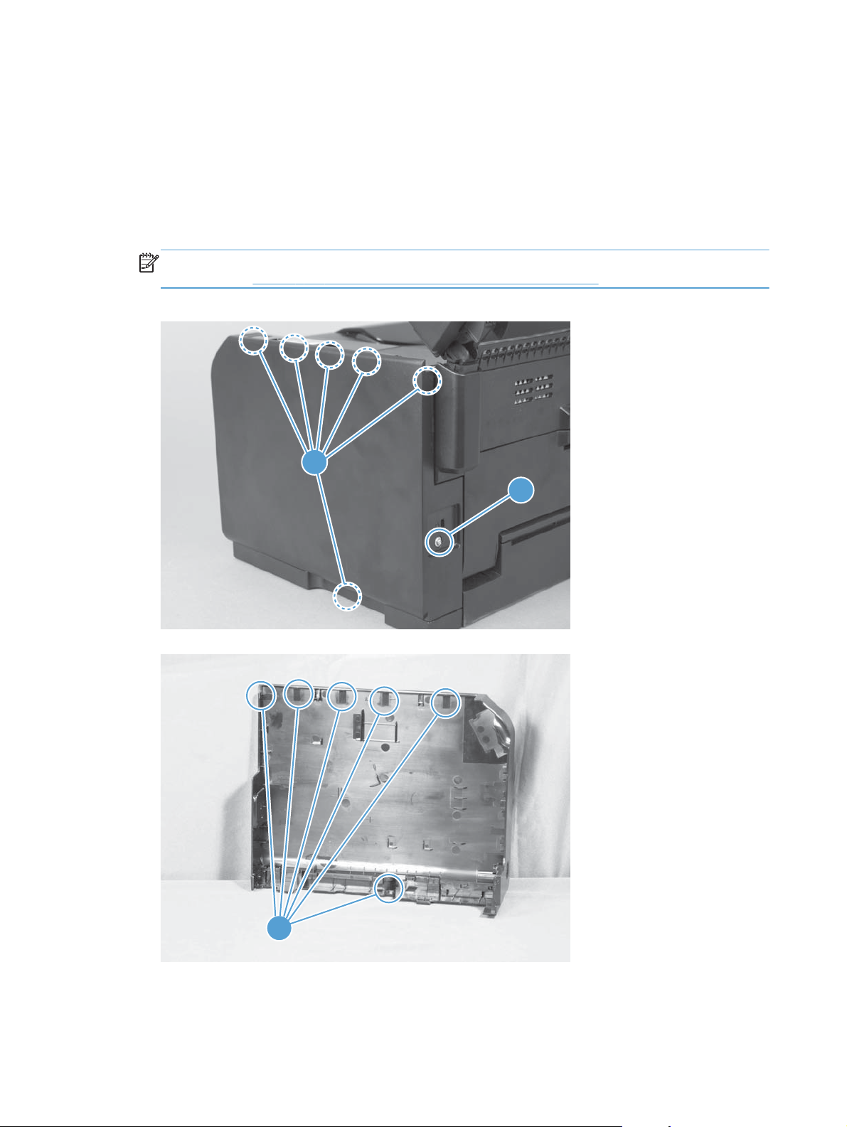
2. Remove one screw (callout 1), and then starting at the rear vertical edge, release six tabs
(callout 2) and remove the right cover.
NOTE: Before proceeding, take note of the locations of the tabs (callout 1) on the back side of
the cover. See
Figure 1-9 Remove the right cover (1 of 2)
Figure 1-10 Remove the right cover (2 of 2) on page 16.
2
1
Figure 1-10 Remove the right cover (2 of 2)
1
16 Chapter 1 Removal and replacement ENWW
Page 31

Left cover
1. Open the document feeder.
2. Remove one screw (callout 1), and then starting at the rear vertical edge, release two tabs
(callout 2) and remove the left cover.
NOTE: Before proceeding, take note of the locations of the tabs (callout 1) on the back side of
the cover. See
Figure 1-11 Remove the left cover (1 of 2)
Figure 1-12 Remove the left cover (2 of 2) on page 17.
2
1
Figure 1-12 Remove the left cover (2 of 2)
1
ENWW
Removal and replacement procedures
17
Page 32

Document feeder
Before proceeding, remove the following components:
Left cover. See
●
Remove the document feeder
1. Release two tabs (callout 1), and then remove the cover (callout 2).
Figure 1-13 Remove the document feeder (1 of 4)
Left cover on page 17.
2
1
18 Chapter 1 Removal and replacement ENWW
Page 33

2. Disconnect two FFCs (callout 1), and then release them from the guides (callout 2).
CAUTION: Do not bend or fold the flat flexible cables (FFCs) during removal or installation.
Also, do not straighten pre-folds in the FFCs.
Figure 1-14 Remove the document feeder (2 of 4)
2
1
3. Release the tabs inside the hinges (callout 1) to allow the scanner assembly to slide down on the
hinges.
Figure 1-15 Remove the document feeder (3 of 4)
1
ENWW
Removal and replacement procedures
19
Page 34

4. Lift and rotate the scanner assembly up and away from the hinges.
Figure 1-16 Remove the document feeder (4 of 4)
1
2
20 Chapter 1 Removal and replacement ENWW
Page 35

Document feeder hinges
Left cover. See
●
Document feeder. See
●
Remove the document feeder hinges
1. Remove one screw (callout 1) from each hinge.
Figure 1-17 Remove the scanner hinges (1 of 2)
Left cover on page 17.
Document feeder on page 18.
1
2. Lift each hinge up to remove it.
Figure 1-18 Remove the scanner hinges (2 of 2)
ENWW
Removal and replacement procedures
21
Page 36

Top door, rear-top cover, and delivery cover
Before proceeding, remove the following components:
Right cover. See
●
Left cover. See
●
Document feeder. See
●
Document feeder hinges. See
●
Remove the top door, rear-top cover, and delivery cover
1. Remove two screws (callout 1 and callout 2).
NOTE: When facing the product, the screw on the right is black (callout 2), and the one on the
left (callout 1) is silver.
Figure 1-19 Remove the top door, rear-top cover, and delivery cover (1 of 6)
Right cover on page 16.
Left cover on page 17.
Document feeder on page 18.
1
Document feeder hinges on page 21.
2
22 Chapter 1 Removal and replacement ENWW
Page 37

2. Open the top door, release the door retainer arm (callout 1), and then close the top door.
Figure 1-20 Remove the top door, rear-top cover, and delivery cover (2 of 6)
1
3. Open the rear door, and then release two tabs on the rear-top cover (callout 1).
Figure 1-21 Remove the top door, rear-top cover, and delivery cover (3 of 6)
1
ENWW
Removal and replacement procedures
23
Page 38

4. Push up on the rear-top cover (callout 1) to slightly raise the delivery cover (callout 2) to release
two rear-top cover tabs (callout 3) along the rear edge of the product.
Figure 1-22 Remove the top door, rear-top cover, and delivery cover (4 of 6)
2
1
3
5. Open the top door (callout 1), rotate the delivery cover and rear-top cover (callout 2) away from
the product, and then slide the door and covers towards the front of the product to release the
assembly.
Figure 1-23 Remove the top door, rear-top cover, and delivery cover (5 of 6)
1
2
24 Chapter 1 Removal and replacement ENWW
Page 39

6. Remove the top door (callout 1) , delivery cover (callout 2), and rear-top cover (callout 3)
assembly.
Figure 1-24 Remove the top door, rear-top cover, and delivery cover (6 of 6)
1
Reinstall the top door, rear-top cover, and delivery cover
Before reassembly, make sure that the two cartridge lock springs (callout 1; located to the right and left
of the print-cartridge opening) are not damaged.
Figure 1-25 Reinstall the top door, rear-top cover, and delivery cover (1 of 2)
2
3
ENWW
1
Removal and replacement procedures
25
Page 40

Figure 1-26 Reinstall the top door, rear-top cover, and delivery cover (1 of 2)
1
26 Chapter 1 Removal and replacement ENWW
Page 41

Rear door assembly
Before proceeding, remove the following components:
Right cover. See
●
Remove the rear door assembly
1. Remove one screw (callout 1) and the bushing (callout 2).
Figure 1-27 Remove the rear door assembly (1 of 2)
Right cover on page 16.
1
2
2. Pull out the shaft (callout 1) and remove the rear door assembly (callout 2).
Figure 1-28 Remove the rear door assembly (2 of 2)
1
2
ENWW
Removal and replacement procedures
27
Page 42

Rear-lower cover
Before proceeding, remove the following components:
Right cover assembly. See
●
Left cover assembly. See
●
Rear door assembly. See
●
Remove the rear-lower cover
Remove two screws (callout 1) and the rear lower cover assembly (callout 2).
Figure 1-29 Remove the rear-lower cover
Right cover on page 16.
Left cover on page 17.
Rear door assembly on page 27.
1
2
28 Chapter 1 Removal and replacement ENWW
Page 43

Control panel
CAUTION: ESD sensitive.
Before proceeding, remove the following components:
Right cover. See
●
Left cover. See
●
Document feeder. See
●
Document feeder hinges. See
●
Top door, rear-top cover, and delivery cover. See
●
on page 22.
Remove the control panel
1. Disconnect one FFC (callout 1), and then release the FFC from the guide (callout 2).
CAUTION: Do not bend or fold the flat flexible cables (FFCs) during removal or installation.
Also, do not straighten pre-folds in the FFCs.
Figure 1-30 Remove the control panel (1 of 3)
Right cover on page 16.
Left cover on page 17.
Document feeder on page 18.
Document feeder hinges on page 21.
Top door, rear-top cover, and delivery cover
2
ENWW
1
Removal and replacement procedures
29
Page 44

2. Remove two screws (callout 1).
Figure 1-31 Remove the control panel (2 of 3)
1
3. Carefully separate the control panel from the product.
NOTE: Guide the FFC through the opening in the product chassis (callout 1) to prevent it from
being damaged when the control-panel is removed.
Figure 1-32 Remove the control panel (3 of 3)
1
30 Chapter 1 Removal and replacement ENWW
Page 45

Left-front cover
Before proceeding, remove the following components:
Right cover. See
●
Left cover. See
●
Document feeder. See
●
Document feeder hinges. See
●
Top door, rear-top cover, and delivery cover. See
●
on page 22.
Control panel. See
●
Remove the left-front cover
1. Remove one screw (callout 1), and then release two tabs (callout 2).
Figure 1-33 Remove the left-front cover (1 of 2)
Left cover on page 17.
Right cover on page 16
Document feeder on page 18.
Document feeder hinges on page 21.
Control panel on page 29.
1
Top door, rear-top cover, and delivery cover
2
ENWW
Removal and replacement procedures
31
Page 46

2. Release on tab (callout 1) by slightly rotating the top of the cover (callout 2) away from the
product.
Figure 1-34 Remove the left-front cover (2 of 2)
2
1
32 Chapter 1 Removal and replacement ENWW
Page 47

Front door
Before proceeding, remove the following components:
Right cover. See
●
Left cover. See
●
Document feeder. See
●
Document feeder hinges. See
●
Top door, rear-top cover, and delivery cover. See
●
on page 22.
Control panel. See
●
Left-front cover. See
●
Remove the front door
1. Open the front door.
2. Remove four screws (callout 1) and the laser/scanner cover (callout 2).
Figure 1-35 Remove the front door (1 of 2)
Right cover on page 16
Left cover on page 17.
Document feeder on page 18.
Document feeder hinges on page 21.
Top door, rear-top cover, and delivery cover
Control panel on page 29.
Left-front cover on page 31.
1
ENWW
2
Removal and replacement procedures
33
Page 48

3. Release one tab (callout 1) and slide the front door (callout 2) to the right to remove it.
Figure 1-36 Remove the front door (2 of 3)
2
1
34 Chapter 1 Removal and replacement ENWW
Page 49

Inner cover
Before proceeding, remove the following components:
Right cover. See
●
Left cover. See
●
Document feeder. See
●
Document feeder hinges. See
●
Top door, rear-top cover, and delivery cover. See
●
on page 22.
Control panel. See
●
Left-front cover. See
●
Remove the inner cover
1. Remove one spring (callout 1), and then remove the door retainer arm (callout 2).
Figure 1-37 Remove the inner cover (1 of 4)
Right cover on page 16
Left cover on page 17.
Document feeder on page 18.
Document feeder hinges on page 21.
Top door, rear-top cover, and delivery cover
Control panel on page 29.
Left-front cover on page 31.
2
1
ENWW
Removal and replacement procedures
35
Page 50

2. Remove three machine screws (callout 1), and then remove one self-tapping screw (callout 2).
Figure 1-38 Remove the inner cover (2 of 4)
1
2
3. Release one tab (callout 1).
Figure 1-39 Remove the inner cover (3 of 4)
1
36 Chapter 1 Removal and replacement ENWW
Page 51

4. Remove the inner cover (callout 1).
Figure 1-40 Remove the inner cover (4 of 4)
1
ENWW
Removal and replacement procedures
37
Page 52

Main assemblies
Formatter PCA (base model)
CAUTION: ESD sensitive.
Before proceeding, remove the following components:
Left cover assembly. See
●
Remove the formatter PCA (base model)
1. Disconnect three connectors (callout 1).
Figure 1-41 Remove the formatter PCA (base model; 1 of 2)
Left cover on page 17.
1
38 Chapter 1 Removal and replacement ENWW
Page 53

2. Remove two screws (callout 1), and then remove the formatter PCA.
Figure 1-42 Remove the formatter PCA (base model; 2 of 2)
1
ENWW
Removal and replacement procedures
39
Page 54

Formatter and wireless PCA (plus model)
CAUTION: ESD sensitive.
Before proceeding, remove the following components:
Left cover. See
●
Remove the formatter and wireless PCA (plus model)
1. Remove one screw (callout 1), and then remove the wireless PCA (callout 2).
Figure 1-43 Remove the formatter and wireless PCA (plus model; 1 of 3)
Left cover on page 17.
2
1
2. Disconnect two connectors (callout 1), and then disconnect four FFCs (callout 2).
Figure 1-44 Remove the formatter and wireless PCA (plus mode; 2 of 3)
2
1
40 Chapter 1 Removal and replacement ENWW
Page 55

3. Remove four screws (callout 1), and then remove the formatter PCA.
Figure 1-45 Remove the formatter and wireless PCA (plus mode; 3 of 3)
1
ENWW
Removal and replacement procedures
41
Page 56

Fuser power supply
CAUTION: ESD sensitive.
Before proceeding, remove the following components:
Left cover. See
●
Remove the fuser power supply
1. Disconnect four connectors (callout 1)
Figure 1-46 Remove the fuser power supply (1 of 2)
Left cover on page 17.
1
2. Remove three screws (callout 1), and then remove the fuser power supply.
Figure 1-47 Remove the fuser power supply (2 of 2)
1
42 Chapter 1 Removal and replacement ENWW
Page 57

ITB assembly
CAUTION: ESD sensitive.
NOTE: If you have not removed the image drum before servicing the product, remove it now. See
Imaging drum on page 9.
Before proceeding, remove the following components:
Right cover. See
●
Left cover. See
●
Document feeder. See
●
Document feeder hinges. See
●
Top door, rear-top cover, and delivery cover. See
●
on page 22.
Rear door. See
●
Rear-lower cover. See
●
Formatter PCA or formatter and wireless PCA. See
●
Formatter and wireless PCA (plus model) on page 40.
Remove the ITB assembly
1. Disconnect four connectors.
Figure 1-48 Remove the ITB assembly (1 of 17)
Right cover on page 16
Left cover on page 17.
Document feeder on page 18.
Document feeder hinges on page 21.
Top door, rear-top cover, and delivery cover
Rear door assembly on page 27.
Rear-lower cover on page 28.
Formatter PCA (base model) on page 38 or
ENWW
1
Removal and replacement procedures
43
Page 58

2. Remove five screws (callout 1), and then separate the sheet-metal plate (callout 2) and fuser power
supply (callout 3) from the product.
CAUTION: The sheet-metal plate and fuser power supply assembly is still attached to the
product by a FFC connected to the engine controller assembly. Do not attempt to completely
remove the assembly.
Figure 1-49 Remove the ITB assembly (2 of 17)
1
2
3
3. Disconnect one FFC (Callout 1), and then remove the sheet-metal plate and fuser power supply
assembly.
Figure 1-50 Remove the ITB assembly (3 of 17)
1
44 Chapter 1 Removal and replacement ENWW
Page 59

4. Release one tab (callout 1), and then remove the cable cover (callout 2).
Figure 1-51 Remove the ITB assembly (4 of 17)
2
1
5. Disconnect one connector (callout 1), release the wire harnesses (callout 2) from the guide (callout
3).
Figure 1-52 Remove the ITB assembly (5 of 17)
1
2
3
ENWW
Removal and replacement procedures
45
Page 60

6. Release one tab (callout 1), and then remove the rear-door left-side arm (callout 2).
Figure 1-53 Remove the ITB assembly (6 of 17)
2
1
7. Release the hook end (callout 1) of the ITB fixing spring (callout 2).
Figure 1-54 Remove the ITB assembly (7 of 17)
1
2
46 Chapter 1 Removal and replacement ENWW
Page 61

8. Rotate the spring (callout 1) so that it faces out of the product.
Figure 1-55 Remove the ITB assembly (8 of 17)
1
ENWW
Removal and replacement procedures
47
Page 62

9. Rotate the ITB fixing part (callout 1) so that it faces out of the product.
Figure 1-56 Remove the ITB assembly (9 of 17)
1
Figure 1-57 Remove the ITB assembly (10 of 17)
1
48 Chapter 1 Removal and replacement ENWW
Page 63

10. Release two tabs (callout 1), and then remove the spring cover (callout 2).
Figure 1-58 Remove the ITB assembly (11 of 17)
1
2
11. Release one tab (callout 1), and the remove the rear-door right-side arm (callout 2).
Figure 1-59 Remove the ITB assembly (12 of 17)
1
2
ENWW
Removal and replacement procedures
49
Page 64

12. Release the hook end (callout 1) of the ITB fixing spring (callout 2), and then pull the wire harness
(callout 3) through the hole in the chassis.
Figure 1-60 Remove the ITB assembly (13 of 17)
3
1
2
13. Rotate the spring (callout 1) so that it faces out of the product.
Figure 1-61 Remove the ITB assembly (14 of 17)
1
50 Chapter 1 Removal and replacement ENWW
Page 65

14. Rotate the ITB fixing part (callout 1) so that it faces out of the product.
Figure 1-62 Remove the ITB assembly (15 of 17)
1
Figure 1-63 Remove the ITB assembly (16 of 17)
1
ENWW
Removal and replacement procedures
51
Page 66

15. Pull the ITB assembly (callout 1) straight out of the product.
CAUTION: Avoid touching the black plastic transfer belt. Skin oils on the belt might cause print-
quality problems.
Figure 1-64 Remove the ITB assembly (17 of 17)
1
52 Chapter 1 Removal and replacement ENWW
Page 67

Fuser delivery assembly
NOTE: For this product, the fuser and the paper delivery components are one assembly.
Position the fuser pressure roller for removal
You must rotate the pressure roller to the correct position before removing the fuser delivery assembly.
1. When the product is in the Ready state, press and hold the Auto-On/Auto-Off (power) button for
about seven seconds or until you hear subtle movement within the product and the Ready light
turns off.
2. Release the Auto-On/Auto-Off (power) button. The product power will be off and the fuser
pressure roller is in the removal position. Unplug the product before removing any components.
NOTE: If you have not removed the image drum before servicing the product, remove it now. See
Imaging drum on page 9.
Before proceeding, remove the following components:
Right cover. See
●
Left cover. See
●
Document feeder. See
●
Document feeder hinges. See
●
Top door, rear-top cover, and delivery cover. See
●
on page 22.
Rear door. See
●
Rear-lower cover. See
●
Formatter PCA or formatter and wireless PCA. See
●
Formatter and wireless PCA (plus model) on page 40.
Right cover on page 16
Left cover on page 17.
Document feeder on page 18.
Document feeder hinges on page 21.
Rear door assembly on page 27.
Rear-lower cover on page 28.
Top door, rear-top cover, and delivery cover
Formatter PCA (base model) on page 38 or
ENWW
Removal and replacement procedures
53
Page 68
Remove the fuser delivery assembly
CAUTION: ESD sensitive.
1. Disconnect four connectors.
Figure 1-65 Remove the fuser delivery assembly (1 of 6)
1
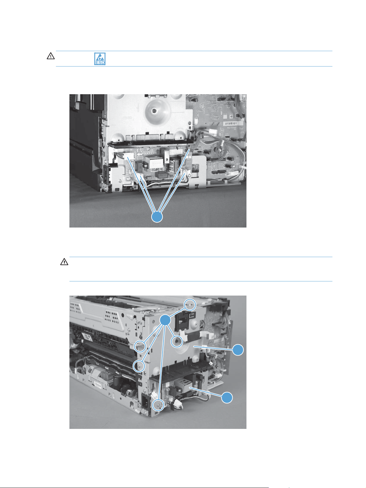
2. Remove five screws (callout 1), and then separate the sheet-metal plate (callout 2) and fuser power
supply (callout 3) from the product.
CAUTION: The sheet-metal plate and fuser power supply assembly is still attached to the
product by a FFC connected to the engine controller assembly. Do not attempt to completely
remove the assembly.
Figure 1-66 Remove the fuser delivery assembly (2 of 6)
1
2
3
54 Chapter 1 Removal and replacement ENWW
Page 69

3. Disconnect one FFC (Callout 1), and then remove the sheet-metal plate and fuser power supply
assembly.
Figure 1-67 Remove the fuser delivery assembly (3 of 6)
1
4. Release one tab (callout 1), and then remove the cable cover (callout 2).
Figure 1-68 Remove the fuser delivery assembly (4 of 6)
2
1
ENWW
Removal and replacement procedures
55
Page 70

5. Disconnect four connectors (callout 1), Release the wire harnesses (callout 2) from the guide
(callout 3).
Figure 1-69 Remove the fuser delivery assembly (5 of 6)
2
3
1
6. Remove six screws (callout 1), and then remove the fuser delivery assembly (callout 2).
Figure 1-70 Remove the fuser delivery assembly (6 of 6)
1
2
56 Chapter 1 Removal and replacement ENWW
Page 71

Reinstall the fuser delivery assembly
When reassembling the fuser delivery assembly, be sure the drive cam (callout 1) for fuser
▲
pressure release is positioned as shown below.
Figure 1-71 Reinstall the fuser delivery assembly (1 of 2)
1
Figure 1-72 Reinstall the fuser delivery assembly (2 of 2)
1
ENWW
Removal and replacement procedures
57
Page 72

Engine controller assembly
CAUTION: ESD sensitive.
Before proceeding, remove the following components:
Right cover. See
●
Left cover. See
●
Document feeder. See
●
Document feeder hinges. See
●
Top door, rear-top cover, and delivery cover. See
●
on page 22.
Control panel. See
●
Left-front cover. See
●
Inner cover. See
●
Formatter PCA or formatter and wireless PCA. See
●
Formatter and wireless PCA (plus model) on page 40.
Remove the engine controller assembly
1. Disconnect four connectors.
Figure 1-73 Remove the engine controller assembly (1 of 7)
Right cover on page 16
Left cover on page 17.
Document feeder on page 18.
Document feeder hinges on page 21.
Control panel on page 29.
Left-front cover on page 31.
Inner cover on page 35.
Top door, rear-top cover, and delivery cover
Formatter PCA (base model) on page 38 or
1
58 Chapter 1 Removal and replacement ENWW
Page 73

2. Remove five screws (callout 1), and then separate the sheet-metal plate (callout 2) and fuser power
supply (callout 3) from the product.
CAUTION: The sheet-metal plate and fuser power supply assembly is still attached to the
product by a FFC connected to the engine controller assembly. Do not attempt to completely
remove the assembly.
Figure 1-74 Remove the engine controller assembly (2 of 7)
1
2
3
3. Disconnect one FFC (Callout 1), and then remove the sheet-metal plate and fuser power supply
assembly.
Figure 1-75 Remove the engine controller assembly (3 of 7)
1
ENWW
Removal and replacement procedures
59
Page 74

4. Release one tab (callout 1) and remove the cable cover (callout 2).
Figure 1-76 Remove the engine controller assembly (4 of 7)
2
1
5. Release one tab (callout 1), and then remove the cover (callout 2).
Figure 1-77 Remove the engine controller assembly (5 of 7)
1
2
60 Chapter 1 Removal and replacement ENWW
Page 75

6. Disconnect eleven connectors (callout 1).
Figure 1-78 Remove the engine controller assembly (6 of 7)
1
7. Remove six screws (callout 1), release two tabs (callout 2), and then remove the engine controller
assembly.
Figure 1-79 Remove the engine controller assembly (7 of 7)
1
2
ENWW
Removal and replacement procedures
61
Page 76

Installing a replacement engine controller assembly
Release one tab (callout 1), remove the guide (callout 2) from the discarded engine controller assembly
(callout 3), and then install the guide on the replacement assembly.
Figure 1-80 Installing a replacement engine controller assembly
3
1
2
62 Chapter 1 Removal and replacement ENWW
Page 77

Low-voltage power supply assembly
CAUTION: ESD sensitive.
Before proceeding, remove the following components:
Right cover. See
●
Left cover. See
●
Document feeder. See
●
Document feeder hinges. See
●
Top door, rear-top cover, and delivery cover. See
●
on page 22.
Rear door. See
●
Rear-lower cover. See
●
Control panel. See
●
Left-front cover. See
●
Inner cover. See
●
Formatter PCA or formatter and wireless PCA. See
●
Formatter and wireless PCA (plus model) on page 40.
Remove the low-voltage power supply assembly
Right cover on page 16
Left cover on page 17.
Document feeder on page 18.
Document feeder hinges on page 21.
Rear door assembly on page 27.
Rear-lower cover on page 28.
Control panel on page 29.
Left-front cover on page 31.
Inner cover on page 35.
Top door, rear-top cover, and delivery cover
Formatter PCA (base model) on page 38 or
1. Disconnect four connectors.
Figure 1-81 Remove the low-voltage power supply assembly (1 of 9)
1
ENWW
Removal and replacement procedures
63
Page 78

2. Remove five screws (callout 1), and then separate the sheet-metal plate (callout 2) and fuser power
supply (callout 3) from the product.
CAUTION: The sheet-metal plate and fuser power supply assembly is still attached to the
product by a FFC connected to the engine controller assembly. Do not attempt to completely
remove the assembly.
Figure 1-82 Remove the low-voltage power supply assembly (2 of 9)
1
2
3
3. Disconnect one FFC (Callout 1), and then remove the sheet-metal plate and fuser power supply
assembly.
Figure 1-83 Remove the low-voltage power supply assembly (3 of 9)
1
64 Chapter 1 Removal and replacement ENWW
Page 79
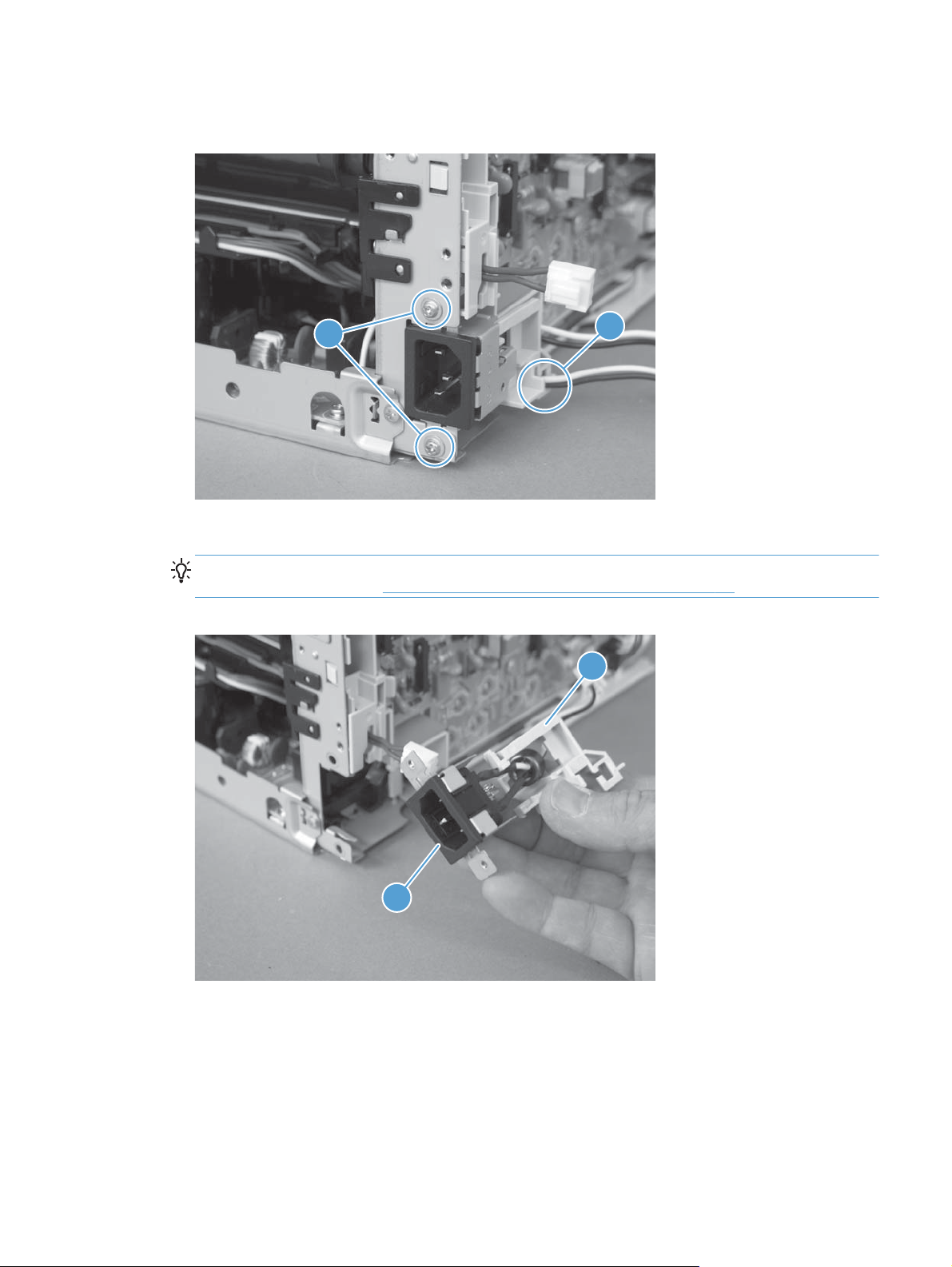
4. Release one cable from the cable guide (callout 1), and then remove two screws (callout 2).
Figure 1-84 Remove the low-voltage power supply assembly (4 of 9)
2
5. Remove the power receptacle (callout 1) and guide (callout 2) as an assembly.
Reinstallation tip Make sure that these parts are correctly assembled, before reinstalling the
receptacle and guide. See
Figure 1-85 Remove the low-voltage power supply assembly (5 of 9)
Reinstall the low-voltage power supply on page 68.
1
2
ENWW
1
Removal and replacement procedures
65
Page 80

6. Place the product rear-side up, and then remove four screws (callout 1).
Figure 1-86 Remove the low-voltage power supply assembly (6 of 9)
1
7. Remove three screws (callout 1), disconnect one connector (callout 2) and separate the low-
voltage power supply assembly (callout 3) from the product.
CAUTION: Do not attempt to completely remove the low-voltage power supply. The power
supply is still connected to the product by three internal connectors.
Figure 1-87 Remove the low voltage power supply assembly (7 of 9)
2
3
1
66 Chapter 1 Removal and replacement ENWW
Page 81

8. Release the wire harness (callout 1) from the guide (callout 2), and then pull the wire harness
through the hole in the chassis.
Figure 1-88 Remove the low-voltage power supply assembly (8 of 9)
2
1
9. Disconnect three connectors (callout 1) and remove the low-voltage power supply assembly
(callout 2).
Figure 1-89 Remove the low-voltage power supply assembly (9 of 9)
1
2
ENWW
Removal and replacement procedures
67
Page 82

Reinstall the low-voltage power supply
Make sure that the power receptacle (callout 1), guide (callout 2), and the ferrite (callout 3) are
correctly assembled before installing them.
Figure 1-90 Reinstall the low-voltage power supply
1 2 3
Installing a replacement low-voltage power supply
Release two tabs (callout 1), remove the cover (callout 2) from the discarded low-voltage power supply,
and then install the guide on the replacement assembly.
Figure 1-91 Installing a replacement low-voltage power supply
2
1
68 Chapter 1 Removal and replacement ENWW
Page 83

Document feeder components
NOTE: This section describes replacement and removal of individual document feeder components.
To remove the complete document feeder, see
Document feeder input tray
1. Open the document feeder cover.
Figure 1-92 Remove the document feeder input tray (1 of 2)
Document feeder on page 18.
2. Hold the scanner cover down, and then pull up on the document feeder tray to release two tabs,
lift the document feeder tray up, and then remove it.
Figure 1-93 Remove the document feeder input tray (2 of 2)
ENWW
Removal and replacement procedures
69
Page 84

Document feeder cover
1. Open the document feeder cover.
Figure 1-94 Remove the document feeder cover (1 of 3)
2. Release one tab (callout 1), and then fully open the document feeder cover.
Figure 1-95 Remove the document feeder cover (2 of 3)
1
70 Chapter 1 Removal and replacement ENWW
Page 85

3. Release the hinges (callout 1), and then remove the document feeder cover.
Figure 1-96 Remove the document feeder cover (3 of 3)
1
ENWW
Removal and replacement procedures
71
Page 86

Document feeder core
Before proceeding, remove the following components:
Document feeder input tray. See
●
Document feeder cover. See
●
Remove the document feeder core
1. Release one tab (callout 1), and then remove the cover (callout 2).
Figure 1-97 Remove the document feeder core (1 of 4)
Document feeder input tray on page 69.
Document feeder cover on page 70.
2
1
2. Disconnect one FFC (callout 1).
Figure 1-98 Remove the document feeder core (2 of 4)
1
72 Chapter 1 Removal and replacement ENWW
Page 87

3. Carefully flex the hinge retainer to release one hinge pin.
Figure 1-99 Remove the document feeder core (3 of 4)
4. Remove the document feeder core.
Figure 1-100 Remove the document feeder core (4 of 4)
ENWW
Removal and replacement procedures
73
Page 88

Post scan pinch rollers
Before proceeding, remove the following components:
Document feeder input tray. See
●
Document feeder cover. See
●
Document feeder core. See
●
Remove the post scan pinch rollers
Remove the post scan pinch rollers (callout 1).
▲
Figure 1-101 Remove the post scan pinch rollers
Document feeder input tray on page 69.
Document feeder cover on page 70.
Document feeder core on page 72.
1
74 Chapter 1 Removal and replacement ENWW
Page 89

Document feeder base assembly
Before proceeding, remove the following components:
Document feeder input tray. See
●
Document feeder cover. See
●
Remove the document feeder base assembly
1. Disconnect one FFC (callout 1), and then release the adhesive FFC protector on the document
feeder base (callout 2).
TIP: Use two-sided tape to replace the FFC protector during reassembly.
Figure 1-102 Remove the document feeder base assembly (1 of 3)
Document feeder input tray on page 69.
Document feeder cover on page 70.
1
2
ENWW
Removal and replacement procedures
75
Page 90

2. Remove two screws (callout 1).
TIP: These screws require a #10 torx driver
Figure 1-103 Remove the document feeder base assembly (2 of 3)
1
3. Open the document feeder base, and then carefully remove it from the product.
CAUTION: Do not damage the FFC (callout 1) that runs through the document feeder base.
Carefully feed the FFC through the slot during removal and during replacement.
Figure 1-104 Remove the document feeder base assembly (3 of 3)
1
76 Chapter 1 Removal and replacement ENWW
Page 91

2 Solve problems
Solve problems checklist
●
Menu map
●
Troubleshooting processes
●
Tools for troubleshooting
●
Service mode functions
●
Product updates
●
ENWW 77
Page 92

Solve problems checklist
Follow these steps when trying to solve a problem with the product.
Step 1: Test print functionality
●
Step 2: Test copy functionality
●
Step 1: Test print functionality
1. Open the Reports menu, and then select Config Report to print the report.
2. If the report does not print, check the following:
3. Make sure that paper is in the tray.
4. Check the control panel for paper jam messages. If the control panel indicates a jam, clear the
jam.
5. Make sure that the print cartridge is not empty.
6. Clean the paper pick roller and the separation pad.
7. Replace the paper pick roller or the separation pad.
Step 2: Test copy functionality
1. Place the configuration page into the document feeder, adjust the paper guides, and then make a
copy. If paper does not feed through the document feeder smoothly, replace the document feeder
pick up arm assembly. If this does not improve the issue, replace the document feeder core
assembly.
2. Place the configuration page onto the scanner glass, and then make a copy.
3. If the print quality on the copied pages is not acceptable, clean the scanner glass.
78 Chapter 2 Solve problems ENWW
Page 93

Menu map
Use the following procedure to print a control-panel menu layout map.
1. On the product control panel, press the Setup button.
2. Use the arrow buttons to select the Reports menu, and then press the OK button.
3. Use the arrow buttons to scroll to the Menu Structure item, and then press the OK button.
4. Press the OK button again to print the report.
ENWW
Menu map
79
Page 94

Troubleshooting processes
Determine the problem source
The following table includes basic questions to ask the customer to quickly help define the problem or
problems.
General topic Questions
Environment
Paper
Input tray
Is the product installed on a solid, level surface (± 1°)?
●
Is the power-supply voltage within ± 10 volts of the specified power source?
●
Is the power-supply plug inserted in the product and the outlet?
●
Is the operating environment within the specified parameters?
●
Is the product exposed to ammonia gas, such as that produced by diazo
●
copiers or office cleaning materials?
NOTE: Diazo copiers produce ammonia gas as part of the coping
processes. Ammonia gas (from cleaning supplies or a diazo copier) can have
an adverse affect on some product components (for example, the imaging
drum).
Is the product exposed to direct sunlight?
●
Does the customer use only supported paper?
●
Is the paper in good condition (no curls, folds, or distortion)?
●
Is the paper stored correctly and within environmental limits?
●
Is the amount of paper in the tray within specifications?
●
Is the paper correctly placed in the tray?
●
Are the paper guides aligned with the stack?
●
Supplies
Transfer roller and fuser
Covers
Are the print cartridges and the imaging-drum installed correctly and firmly
●
seated?
Has the sealing tape been removed from each print cartridge?
●
Are the print cartridges and imaging drum within their estimated life? (Check
●
the supplies status page.)
Are the transfer roller and fuser installed correctly?
●
Are the top, front and rear doors firmly closed?
●
80 Chapter 2 Solve problems ENWW
Page 95

General topic Questions
Condensation
Miscellaneous
Power subsystem
Power-on checks
Turn on the power. If the control-panel LEDs do not illuminate, perform the power-on checks to find the
cause of the problem.
1. Verify that the product is plugged into an active electrical outlet that delivers the correct voltage.
2. Verify that the power button is in the on position.
Does condensation occur following a temperature change (particularly in
●
winter following cold storage)? If so, wipe affected parts dry or leave the
product on for 90 to 120 minutes.
Was a cartridge opened soon after being moved from a cold to a warm
●
room? If so, allow the cartridge to sit at room temperature for 1 to 2 hours.
Check for and remove any non-HP components (for example, a print cartridge
●
or imaging drum) from the product.
Remove the product from the network and make sure that the failure is with the
●
product before beginning troubleshooting.
3. Make sure that the product makes the expected start up sounds.
NOTE: The overcurrent/overvoltage protection circuit in the low-voltage power supply unit might
be functioning. Turn the product off, unplug the power cord, and turn the product on. If the
product does not function, the fuse melts, or the power supply is malfunctioning, replace the
engine controller unit. See
Engine controller assembly on page 58.
ENWW
Troubleshooting processes
81
Page 96

Tools for troubleshooting
Component diagnostics
Component tests
Control-panel tests
The product includes diagnostic tests for the control panel.
Test the control-panel display
1. Press the Setup button.
2. Press the left arrow
3. Press the Setup button to return to the main menus.
4. Open the Secondary service menu.
5. Open the Display test menu.
Test the control-panel buttons
1. Press the Setup button.
2. Press the left arrow
3. Press the Setup button to return to the main menus.
4. Open the Secondary service menu.
5. Open the Button test menu.
button, and then quickly press the Cancel button.
button, and then quickly press the Cancel button.
82 Chapter 2 Solve problems ENWW
Page 97

Diagrams
Locations of connectors
Figure 2-1 Locations of connectors
J103
J128
J130
J106
J107
J119
J102
J108
J101
J109
J152
J104
J110
J112
J140
Item Description Item Description Item Description
J101 Not used J107 Media width
sensor (SR1)
J119 Fuser pressure
release sensor
(SR4)
Delivery sensor
(SR2)
J102 Not used J108 Low-voltage power
supply
J128 Rear door open
detection switch
(SW1)
TOP sensor (SR6)
J103 Formatter J109 Memory tag
Scanner motor
(M5)
Power switch PCA
Carousel home
sensor (SR7)
J104 Scanner assembly
(laser drive PCA)
J110 Carousel motor
(M1)
Fuser motor (M2)
J106 Loop sensor (SR3) J112 Pickup motor (M3)
T2 roller and ITB
cleaner solenoid
(SL1)
J130 ITB
J140 Low-voltage power
supply
J152 Not used
ENWW
Tools for troubleshooting
83
Page 98

Locations of major components
Figure 2-2 Cross section view
Item Description Item Description
1 Pressure roller 10 T1 pad
2 Delivery roller 11 ITB
3 Fuser film assembly 12 Pickup roller
4 Density ITB_TOP sensor 13 Separation pad
5 Print cartridge 14 Feed roller
6 Imaging drum 15 T2 roller
7 Imaging-drum 16 ITB drive roller
8 Laser scanner assembly 17 ITB cleaning brush
9 Input tray 18 ITB cleaning roller
84 Chapter 2 Solve problems ENWW
Page 99

Figure 2-3 External covers and doors (base)
11
10
7
1
9
2
8
3
4
5
6
Table 2-1 External covers and doors (base)
Item Description Item Description
1 Right-top cover 7 Right cover
2 Front door 8 Left-front cover
3 Input tray 9 Inner cover
4 Rear-top cover 10 Left cover
5 Rear door 11 Top door
6Rear-bottom cover
ENWW
Tools for troubleshooting
85
Page 100

General timing chart
Figure 2-4 General timing diagram
PRINTINTR LSTR
Print command
STBY STBY
Operation
T1 bias
Fuser motor
TOP sensor3
4 Delivery sensor
2 Pickup motor
Timing chart two consecutive prints on LTR paper (Full-color 1/1 speed mode)
1 Cassette pickup solenoid
5
Main motor7
6 Scanner motor
9 ITB_TOP signal
8 TOP signal
12 Developing bias
11 Carousel motor
10 Primary charging bias
T2 roller ITB cleaner solenoid
13
15 T2 bias
14
86 Chapter 2 Solve problems ENWW
 Loading...