

Page 1
LASERJET PROFESSIONAL M1130/M1210
MFP SERIES
Service Manual
Page 2

Page 3

HP LaserJet Professional M1130/M1210
MFP series
Service Manual
Page 4

Copyright and License
Trademark Credits
© 2010 Copyright Hewlett-Packard
Development Company, L.P.
Reproduction, adaptation, or translation
without prior written permission is prohibited,
except as allowed under the copyright laws.
The information contained herein is subject
to change without notice.
The only warranties for HP products and
services are set forth in the express warranty
statements accompanying such products
and services. Nothing herein should be
construed as constituting an additional
warranty. HP shall not be liable for technical
or editorial errors or omissions contained
herein.
Part number: CE841-90985
Edition 1, 4/2010
Microsoft®, Windows®, Windows® XP, and
Windows Vista® are U.S. registered
trademarks of Microsoft Corporation.
Page 5

Conventions used in this guide
TIP: Tips provide helpful hints or shortcuts.
NOTE: Notes provide important information to explain a concept or to complete a task.
CAUTION: Cautions indicate procedures that you should follow to avoid losing data or damaging the
product.
WARNING! Warnings alert you to specific procedures that you should follow to avoid personal injury,
catastrophic loss of data, or extensive damage to the product.
ENWW iii
Page 6

iv Conventions used in this guide ENWW
Page 7

Table of contents
1 Removal and replacement ............................................................................................................................. 1
Introduction ........................................................................................................................................... 2
Removal and replacement strategy ..................................................................................................... 2
Electrostatic discharge ......................................................................................................................... 3
Required tools ..................................................................................................................................... 3
Before performing service .................................................................................................................... 4
After performing service ....................................................................................................................... 4
Post-service test ................................................................................................................................... 5
Print-quality test ................................................................................................................... 5
Parts removal order .............................................................................................................................. 6
Pickup roller .......................................................................................................................................... 9
Product base pickup roller ................................................................................................... 9
ADF pre-pickup arm and pickup roller ............................................................................... 10
Remove the ADF pre-pickup arm and pickup roller .......................................... 10
Reinstall the ADF pre-pickup arm and pickup roller .......................................... 12
Separation pad ................................................................................................................................... 13
Product base separation pad ............................................................................................. 13
ADF separation pad .......................................................................................................... 14
Reinstall the ADF separation pad assembly ...................................................................... 16
Transfer roller ..................................................................................................................................... 19
Covers ................................................................................................................................................ 20
Paper-pickup tray (input tray) ............................................................................................ 20
Paper-delivery tray (output bin extension) ......................................................................... 21
Left cover ........................................................................................................................... 22
Remove the left cover ....................................................................................... 22
Right cover ......................................................................................................................... 25
Remove the right cover ..................................................................................... 25
Front cover ......................................................................................................................... 28
Remove the front cover ..................................................................................... 28
Scanner assembly ............................................................................................................. 30
Remove the scanner assembly ......................................................................... 30
Cartridge door .................................................................................................................... 33
Remove the cartridge door ................................................................................ 33
Top cover ........................................................................................................................... 36
ENWW v
Page 8

Remove the top cover ....................................................................................... 36
Rear cover ......................................................................................................................... 38
Remove the rear cover ...................................................................................... 38
Reinstall the rear cover ...................................................................................................... 40
Scanner components ......................................................................................................................... 41
White plate (document backing) ........................................................................................ 41
ADF top cover .................................................................................................................... 43
ADF core ............................................................................................................................ 45
Remove the ADF core ....................................................................................... 45
ADF tray ............................................................................................................................. 48
Remove the ADF tray ........................................................................................ 48
ADF base or scanner assembly lid .................................................................................... 51
Remove the ADF base or scanner assembly lid ............................................... 51
Scanner assembly bezel .................................................................................................... 53
Remove the scanner assembly bezel ............................................................... 53
Scanner assembly latch ..................................................................................................... 55
Remove the scanner assembly latch ................................................................ 55
CIS scanner-carriage assembly ......................................................................................... 56
Remove the CIS scanner-carriage assembly .................................................... 56
CIS scanner motor, gears, and scanner light bar .............................................................. 58
Remove the CIS scanner motor, gears, and scanner light bar ......................... 58
CIS scanner drive gears .................................................................................................... 61
Remove the CIS scanner drive gears ............................................................... 61
Main assemblies ................................................................................................................................. 62
Control-panel assembly ..................................................................................................... 62
Remove the control-panel assembly ................................................................. 62
Reinstall the control-panel assembly ................................................................ 64
Power switch assembly ..................................................................................................... 66
Remove the power switch assembly ................................................................. 66
Formatter PCA ................................................................................................................... 68
Remove the formatter PCA ............................................................................... 68
Fax PCA ............................................................................................................................ 70
Remove the Fax PCA ....................................................................................... 70
Laser/scanner assembly .................................................................................................... 71
Remove the laser/scanner assembly ................................................................ 71
Reinstall the laser/scanner assembly ................................................................ 73
Main motor ......................................................................................................................... 74
Remove the main motor .................................................................................... 74
Reinstall the main-motor drive belt .................................................................... 78
Fuser .................................................................................................................................. 79
Remove the fuser .............................................................................................. 79
Reinstall the fuser ............................................................................................. 83
Pickup assembly ................................................................................................................ 84
Remove the pickup assembly ........................................................................... 84
vi ENWW
Page 9

Reinstall the pickup assembly ........................................................................... 88
Pickup solenoid .................................................................................................................. 90
Remove the pickup solenoid ............................................................................. 90
Engine controller PCA ....................................................................................................... 94
Remove the engine controller PCA ................................................................... 94
Reinstall the engine controller PCA .................................................................. 98
2 Solve problems ........................................................................................................................................... 101
Solve problems checklist .................................................................................................................. 102
Troubleshooting process .................................................................................................................. 105
Determine the problem source ....................................................................................... 105
Power subsystem ............................................................................................................ 106
Power-on checks ............................................................................................. 106
Tools for troubleshooting .................................................................................................................. 107
Individual component diagnostics .................................................................................... 107
Engine diagnostics .......................................................................................... 107
Engine-test button .......................................................................... 107
Components tests ........................................................................................... 108
Drum rotation functional check ...................................................... 108
Half self-test functional check ......................................................... 108
Diagrams ......................................................................................................................... 109
Plug/jack locations .......................................................................................... 109
HP LaserJet Professional M1130 MFP series ................................ 109
HP LaserJet Professional M1210 MFP series ................................ 110
Location of connectors .................................................................................... 111
Locations of major components ...................................................................... 112
General timing charts ...................................................................................... 115
General circuit diagram ................................................................................... 116
Internal print-quality test pages ........................................................................................ 117
Cleaning page ................................................................................................. 117
Configuration page .......................................................................................... 118
Print-quality troubleshooting tools .................................................................................... 119
Repetitive defect ruler ..................................................................................... 119
Interpret control-panel light patterns (HP LaserJet Professional M1130 MFP series
only) ................................................................................................................................. 120
Interpret control-panel messages (HP LaserJet Professional M1210 MFP series
only) ................................................................................................................................. 123
Control-panel message types ......................................................................... 123
Control-panel messages ................................................................................. 123
Clear jams ........................................................................................................................................ 126
Common causes of jams ................................................................................................. 126
Jam locations ................................................................................................................... 127
Clear jams from the document feeder (HP LaserJet Professional M1210 MFP series
only) ................................................................................................................................. 128
ENWW vii
Page 10

Clear jams from the output areas .................................................................................... 129
Clear jams from the input tray .......................................................................................... 131
Clear jams from inside the product .................................................................................. 133
Solve repeated jams ........................................................................................................ 135
Change jam recovery ...................................................................................................... 136
Solve paper-handling problems ........................................................................................................ 137
Solve image-quality problems .......................................................................................................... 138
Image defects table ......................................................................................................... 138
General print-quality issues ............................................................................. 138
Copy print-quality problems ............................................................................ 142
Scan-quality problems ..................................................................................... 143
Prevent scan-quality problems ....................................................... 143
Solve scan-quality problems ........................................................... 143
Optimize and improve image quality ................................................................................ 144
Change print density ....................................................................................... 144
Manage and configure printer drivers ............................................................ 144
Clean the product ............................................................................................................................. 145
Clean the pickup roller ..................................................................................................... 145
Clean the separation pad ................................................................................................. 149
Clean the paper path ....................................................................................................... 152
Clean the print-cartridge area .......................................................................................... 154
Clean the exterior ............................................................................................................ 157
Clean the scanner glass strip and platen ......................................................................... 158
Solve performance problems ........................................................................................................... 159
Solve connectivity problems ............................................................................................................ 160
Solve direct-connect problems ........................................................................................ 160
Solve network problems .................................................................................................. 160
Solve fax problems (HP LaserJet Professional M1210 MFP series only) ........................................ 162
Fax troubleshooting checklist .......................................................................................... 162
Fax error messages ........................................................................................................ 163
Alert and warning messages ........................................................................... 163
Fax logs and reports ........................................................................................................ 168
Print all fax reports .......................................................................................... 168
Print individual fax reports ............................................................................... 169
Set the fax activity log to print automatically ................................................... 169
Set the fax error report .................................................................................... 169
Set the fax confirmation report ........................................................................ 170
Include the first page of each fax on the fax confirmation, fax error, and last
call reports ....................................................................................................... 170
Change error correction and fax speed ........................................................................... 170
Set the fax-error-correction mode ................................................................... 170
Change the fax speed ..................................................................................... 171
Problems sending faxes .................................................................................................. 171
Problems receiving faxes ................................................................................................. 174
viii ENWW
Page 11

Service mode functions .................................................................................................................... 177
Product resets .................................................................................................................. 177
Product updates ............................................................................................................................... 178
3 Parts and diagrams ..................................................................................................................................... 179
Order parts by authorized service providers .................................................................................... 180
Order replacement parts .................................................................................................. 180
Related documentation and software .............................................................................. 180
Supplies part numbers ..................................................................................................... 180
Customer replaceable units (CRU) kit part numbers ....................................................... 181
Whole-unit replacement part numbers ............................................................................. 182
How to use the parts lists and diagrams .......................................................................................... 183
Assembly locations ........................................................................................................................... 184
Base product (no optional trays or accessories) .............................................................. 184
Assembly views ................................................................................................................................ 186
Assembly view, HP LaserJet Professional M1130 MFP series ....................................... 186
Assembly view, HP LaserJet Professional M1210 MFP series ....................................... 188
Scanner and ADF assemblies .......................................................................................................... 190
Scanner assembly (1 of 2); HP LaserJet Professional M1130 MFP series ..................... 190
Scanner assembly (2 of 2); HP LaserJet Professional M1130 MFP series ..................... 192
Scanner drive assembly; HP LaserJet Professional M1130 MFP series ......................... 194
ADF/scanner assembly; HP LaserJet Professional M1210 MFP series .......................... 196
Scanner assembly; HP LaserJet Professional M1210 MFP series ................................. 198
Scanner drive assembly; HP LaserJet Professional M1210 MFP series ......................... 200
ADF assembly; HP LaserJet Professional M1210 MFP series ........................................ 202
ADF top cover; HP LaserJet Professional M1210 MFP series ........................................ 204
ADF core; HP LaserJet Professional M1210 MFP series ................................................ 206
ADF Base; HP LaserJet Professional M1210 MFP series ............................................... 208
Covers .............................................................................................................................................. 210
Product base .................................................................................................................... 210
Internal assemblies .......................................................................................................................... 212
Internal assemblies (1 of 3) ............................................................................................. 212
Internal assemblies (2 of 3) ............................................................................................. 214
Internal assemblies (3 of 3) ............................................................................................. 216
PCAs ................................................................................................................................................ 218
Alphabetical parts list ....................................................................................................................... 220
Numerical parts list ........................................................................................................................... 227
Appendix A Service and support ................................................................................................................. 235
Hewlett-Packard limited warranty statement .................................................................................... 236
HP's Premium Protection Warranty: LaserJet print cartridge limited warranty statement ................ 237
End User License Agreement .......................................................................................................... 238
Customer self-repair warranty service .............................................................................................. 240
ENWW ix
Page 12

Customer support ............................................................................................................................. 240
Repack the product .......................................................................................................................... 241
Service information form .................................................................................................................. 242
Appendix B Specifications ............................................................................................................................ 243
Physical specifications ..................................................................................................................... 244
Power consumption .......................................................................................................................... 244
Acoustic specifications ..................................................................................................................... 244
Environmental specifications ............................................................................................................ 245
Appendix C Regulatory information ............................................................................................................ 247
FCC regulations ............................................................................................................................... 248
Declaration of conformity (base model) ............................................................................................ 249
Declaration of conformity (fax model) ............................................................................................... 250
Certificate of Volatility ....................................................................................................................... 251
Safety statements ............................................................................................................................. 253
Laser safety ..................................................................................................................... 253
Canadian DOC regulations .............................................................................................. 253
Power cord instructions ................................................................................................... 253
EMC statement (Korea) ................................................................................................... 253
Laser statement for Finland ............................................................................................. 254
GS statement (Germany) ................................................................................................. 254
Substances Table (China) ............................................................................................... 255
Restriction on Hazardous Substances statement (Turkey) ............................................. 255
Additional statements for telecom (fax) products ............................................................................. 256
EU Statement for Telecom Operation .............................................................................. 256
New Zealand Telecom Statements .................................................................................. 256
Additional FCC statement for telecom products (US) ...................................................... 256
Telephone Consumer Protection Act (US) ...................................................................... 257
Industry Canada CS-03 requirements ............................................................................. 257
Index ................................................................................................................................................................. 259
x ENWW
Page 13

List of tables
Table 2-1 Basic problem solving .................................................................................................................... 102
Table 2-2 Status-light legend ......................................................................................................................... 120
Table 2-3 Control-panel light patterns ............................................................................................................ 120
Table 3-1 Order parts, accessories, and supplies .......................................................................................... 180
Table 3-2 Related documentation and software ............................................................................................ 180
Table 3-3 Supplies part numbers ................................................................................................................... 180
Table 3-4 Customer replaceable units (CRU) kit part numbers ..................................................................... 181
Table 3-5 Whole-unit replacement part numbers ........................................................................................... 182
Table 3-6 Assembly view, HP LaserJet Professional M1130 MFP series ..................................................... 187
Table 3-7 Assembly view, HP LaserJet Professional M1210 MFP series .................................................... 189
Table 3-8 Scanner assembly (1 of 2); HP LaserJet Professional M1130 MFP series ................................... 191
Table 3-9 Scanner assembly (2 of 2); HP LaserJet Professional M1130 MFP series ................................... 193
Table 3-10 Scanner drive assembly; HP LaserJet Professional M1130 MFP series ..................................... 195
Table 3-11 ADF/scanner assembly; HP LaserJet Professional M1210 MFP series ...................................... 197
Table 3-12 ADF/scanner assembly; HP LaserJet Professional M1210 MFP series ...................................... 199
Table 3-13 Scanner drive assembly; HP LaserJet Professional M1210 MFP series ..................................... 201
Table 3-14 ADF assembly; HP LaserJet Professional M1210 MFP series .................................................... 203
Table 3-15 ADF top cover; HP LaserJet Professional M1210 MFP series .................................................... 205
Table 3-16 ADF core; HP LaserJet Professional M1210 MFP series ............................................................ 207
Table 3-17 ADF pre-pick arm assembly; HP LaserJet Professional M1210 MFP series ............................... 209
Table 3-18 Product base ................................................................................................................................ 211
Table 3-19 Internal assemblies (1 of 3) .......................................................................................................... 213
Table 3-20 Internal assemblies (2 of 3) .......................................................................................................... 215
Table 3-21 Internal assemblies (3 of 3) .......................................................................................................... 217
Table 3-22 PCAs ............................................................................................................................................ 219
Table 3-23 Alphabetical parts list ................................................................................................................... 220
Table 3-24 Numerical parts list ....................................................................................................................... 227
Table B-1 Physical specifications
Table B-2 HP LaserJet Professional M1130/M1210 MFP series (average in watts)
Table B-3 HP LaserJet Professional M1130/M1210 MFP series
Table B-4 Environmental specifications ......................................................................................................... 245
1
.................................................................................................................. 244
123
.................................. 244
12
................................................................ 244
ENWW xi
Page 14

xii ENWW
Page 15

List of figures
Figure 1-1 Phillips and pozidrive screwdriver comparison ................................................................................. 3
Figure 1-2 Parts removal order; HP LaserJet Professional M1210 MFP series ADF/scanner .......................... 6
Figure 1-3 Parts removal order; HP LaserJet Professional M1130 MFP series scanner ................................... 7
Figure 1-4 Parts removal order; product base .................................................................................................... 7
Figure 1-5 Remove the product base pickup roller (1 of 2) ................................................................................ 9
Figure 1-6 Remove the product base pickup roller (2 of 2) ................................................................................ 9
Figure 1-7 Remove the ADF pre-pickup arm and pickup roller assembly (1 of 4) ........................................... 10
Figure 1-8 Remove the ADF pre-pickup arm and pickup roller assembly (2 of 4) ........................................... 10
Figure 1-9 Remove the ADF pre-pickup arm and pickup roller assembly (3 of 4) ........................................... 11
Figure 1-10 Remove the ADF pre-pickup arm and pickup roller assembly (4 of 4) ......................................... 11
Figure 1-11 Reinstall the ADF pre-pickup arm and pickup roller assembly gears ........................................... 12
Figure 1-12 Remove the product base separation pad assembly .................................................................... 13
Figure 1-13 Remove the ADF separation pad assembly (1 of 4) ..................................................................... 14
Figure 1-14 Remove the ADF separation pad assembly (2 of 4) ..................................................................... 14
Figure 1-15 Remove the ADF separation pad assembly (3 of 4) ..................................................................... 15
Figure 1-16 Remove the ADF separation pad assembly (4 of 4) ..................................................................... 15
Figure 1-17 Reinstall the ADF separation pad assembly (1 of 5) .................................................................... 16
Figure 1-18 Reinstall the ADF separation pad assembly (2 of 5) .................................................................... 16
Figure 1-19 Reinstall the ADF separation pad assembly (3 of 5) .................................................................... 17
Figure 1-20 Reinstall the ADF separation pad assembly (4 of 5) .................................................................... 17
Figure 1-21 Reinstall the ADF separation pad assembly (5 of 5) .................................................................... 18
Figure 1-22 Remove the transfer roller ............................................................................................................ 19
Figure 1-23 Remove the paper-pickup tray (1 of 2) ......................................................................................... 20
Figure 1-24 Remove the paper-pickup tray (2 of 2) ......................................................................................... 20
Figure 1-25 Remove the paper-delivery tray .................................................................................................... 21
Figure 1-26 Remove the paper-pickup tray (2 of 2) ......................................................................................... 21
Figure 1-27 Remove the left cover (1 of 6) ....................................................................................................... 22
Figure 1-28 Remove the left cover (2 of 6) ....................................................................................................... 22
Figure 1-29 Remove the left cover (3 of 6) ....................................................................................................... 23
Figure 1-30 Remove the left cover (4 of 6) ....................................................................................................... 23
Figure 1-31 Remove the left cover (5 of 6) ....................................................................................................... 24
Figure 1-32 Remove the left cover (6 of 6) ....................................................................................................... 24
Figure 1-33 Remove the left cover (1 of 5) ....................................................................................................... 25
Figure 1-34 Remove the left cover (2 of 5) ....................................................................................................... 25
ENWW xiii
Page 16

Figure 1-35 Remove the right cover (3 of 5) .................................................................................................... 26
Figure 1-36 Remove the left cover (4 of 5) ....................................................................................................... 26
Figure 1-37 Remove the right cover (5 of 5) .................................................................................................... 27
Figure 1-38 Remove the front cover (1 of 4) .................................................................................................... 28
Figure 1-39 Remove the front cover (2 of 4) .................................................................................................... 28
Figure 1-40 Remove the front cover (3 of 4) .................................................................................................... 29
Figure 1-41 Remove the front cover (4 of 4) .................................................................................................... 29
Figure 1-42 Remove the scanner assembly (1 of 5; HP LaserJet Professional M1130 MFP series) .............. 30
Figure 1-43 Remove the scanner assembly (2 of 5; HP LaserJet Professional M1210 MFP series) .............. 30
Figure 1-44 Remove the scanner assembly (3 of 5) ........................................................................................ 31
Figure 1-45 Remove the scanner assembly (4 of 5) ........................................................................................ 31
Figure 1-46 Remove the scanner assembly (5 of 5) ........................................................................................ 32
Figure 1-47 Remove the cartridge door (1 of 5) ............................................................................................... 33
Figure 1-48 Remove the cartridge door (2 of 5) ............................................................................................... 34
Figure 1-49 Remove the cartridge door (3 of 5) ............................................................................................... 34
Figure 1-50 Remove the cartridge door (4 of 5) ............................................................................................... 35
Figure 1-51 Remove the cartridge door (5 of 5) ............................................................................................... 35
Figure 1-52 Remove the top cover (1 of 2) ...................................................................................................... 36
Figure 1-53 Remove the top cover (2 of 2) ...................................................................................................... 37
Figure 1-54 Remove the rear cover (1 of 2) ..................................................................................................... 38
Figure 1-55 Remove the rear cover (2 of 2) ..................................................................................................... 39
Figure 1-56 Rear cover and bracket correctly positioned ................................................................................ 40
Figure 1-57 Rear cover and bracket incorrectly positioned .............................................................................. 40
Figure 1-58 Remove the white plate (1 of 3) .................................................................................................... 41
Figure 1-59 Remove the white plate (2 of 3) .................................................................................................... 42
Figure 1-60 Remove the white plate (3 of 3) .................................................................................................... 42
Figure 1-61 Remove the ADF top cover (1 of 4) .............................................................................................. 43
Figure 1-62 Remove the ADF top cover (2 of 4) .............................................................................................. 43
Figure 1-63 Remove the ADF top cover (3 of 4) .............................................................................................. 44
Figure 1-64 Remove the ADF top cover (4 of 4) .............................................................................................. 44
Figure 1-65 Remove the ADF core (1 of 5) ...................................................................................................... 45
Figure 1-66 Remove the ADF core (2 of 5) ...................................................................................................... 46
Figure 1-67 Remove the ADF core (3 of 5) ...................................................................................................... 46
Figure 1-68 Remove the ADF core (4 of 5) ...................................................................................................... 47
Figure 1-69 Remove the ADF core (5 of 5) ...................................................................................................... 47
Figure 1-70 Remove the ADF tray (1 of 4) ....................................................................................................... 48
Figure 1-71 Remove the ADF tray (2 of 4) ....................................................................................................... 49
Figure 1-72 Remove the ADF tray (3 of 4) ....................................................................................................... 49
Figure 1-73 Remove the ADF tray (4 of 4) ....................................................................................................... 50
Figure 1-74 Remove the ADF base or scanner assembly lid (1 of 3) .............................................................. 51
Figure 1-75 Remove the ADF base or scanner assembly lid (2 of 3) .............................................................. 52
Figure 1-76 Remove the ADF base or scanner assembly lid (3 of 3) .............................................................. 52
Figure 1-77 Remove the scanner assembly bezel (1 of 2; HP LaserJet Professional M1130 MFP
series) ................................................................................................................................................................. 53
xiv ENWW
Page 17

Figure 1-78 Remove the scanner assembly bezel (2 of 2; HP LaserJet Professional M1210 MFP
series) ................................................................................................................................................................. 54
Figure 1-79 Remove the scanner assembly latch ............................................................................................ 55
Figure 1-80 Remove the CIS scanner-carriage assembly (1 of 2) ................................................................... 56
Figure 1-81 Remove the CIS scanner-carriage assembly (2 of 2) ................................................................... 57
Figure 1-82 Remove the CIS scanner motor, gears, and scanner light bar (1 of 4) ........................................ 58
Figure 1-83 Remove the CIS scanner motor, gears, and scanner light bar (2 of 4) ........................................ 59
Figure 1-84 Remove the CIS scanner motor, gears, and scanner light bar (3 of 4) ........................................ 59
Figure 1-85 Remove the CIS scanner motor, gears, and scanner light bar (4 of 4) ........................................ 60
Figure 1-86 Remove the CIS scanner motor and gears ................................................................................. 61
Figure 1-87 Remove the control-panel assembly (1 of 5; HP LaserJet Professional M1130 MFP
series) ................................................................................................................................................................. 62
Figure 1-88 Remove the control-panel assembly (2 of 5; HP LaserJet Professional M1210 MFP
series) ................................................................................................................................................................. 62
Figure 1-89 Remove the control-panel assembly (3 of 5) ................................................................................ 63
Figure 1-90 Remove the control-panel assembly (4 of 5) ................................................................................ 63
Figure 1-91 Remove the control-panel assembly (5 of 5) ................................................................................ 64
Figure 1-92 Reinstall the control-panel assembly (1 of 2) ................................................................................ 64
Figure 1-93 Reinstall the control-panel assembly (2 of 2) ................................................................................ 65
Figure 1-94 Remove the power switch assembly (1 of 3) ................................................................................ 66
Figure 1-95 Remove the power switch assembly (2 of 3) ................................................................................ 66
Figure 1-96 Remove the power switch assembly (3 of 3) ................................................................................ 67
Figure 1-97 Remove the formatter PCA (1 of 4; HP LaserJet Professional M1130 MFP series) .................... 68
Figure 1-98 Remove the formatter PCA (2 of 4; HP LaserJet Professional M1210 MFP series) .................... 68
Figure 1-99 Remove the formatter PCA (3 of 4; HP LaserJet Professional M1130 MFP series) .................... 69
Figure 1-100 Remove the formatter PCA (4 of 4; HP LaserJet Professional M1210 MFP series) .................. 69
Figure 1-101 Remove the Fax PCA ................................................................................................................. 70
Figure 1-102 Remove the laser/scanner assembly (1 of 3) ............................................................................. 71
Figure 1-103 Remove the laser/scanner assembly (2 of 3) ............................................................................. 72
Figure 1-104 Remove the laser/scanner assembly (3 of 3) ............................................................................. 72
Figure 1-105 Reinstall the laser/scanner assembly ......................................................................................... 73
Figure 1-106 Remove the laser/scanner assembly (1 of 7) ............................................................................. 74
Figure 1-107 Remove the laser/scanner assembly (2 of 7) ............................................................................. 75
Figure 1-108 Remove the main motor (3 of 7) ................................................................................................. 75
Figure 1-109 Remove the main motor (4 of 7) ................................................................................................. 76
Figure 1-110 Remove the main motor (5 of 7) ................................................................................................. 76
Figure 1-111 Remove the main motor (6 of 7) ................................................................................................. 77
Figure 1-112 Remove the main motor (7 of 7) ................................................................................................. 77
Figure 1-113 Main-motor drive belt: correctly installed .................................................................................... 78
Figure 1-114 Main-motor drive belt: incorrectly installed .................................................................................. 78
Figure 1-115 Remove the fuser (1 of 6) ........................................................................................................... 79
Figure 1-116 Remove the fuser (2 of 6) ........................................................................................................... 80
Figure 1-117 Remove the fuser (3 of 6) ........................................................................................................... 80
Figure 1-118 Remove the fuser (4 of 6) ........................................................................................................... 81
ENWW xv
Page 18

Figure 1-119 Remove the fuser (5 of 6) ........................................................................................................... 81
Figure 1-120 Remove the fuser (6 of 6) ........................................................................................................... 82
Figure 1-121 Reinstall the fuser; correct wire harness installation ................................................................... 83
Figure 1-122 Reinstall the fuser; incorrect wire harness installation ................................................................ 83
Figure 1-123 Remove the pickup assembly (1 of 6) ........................................................................................ 84
Figure 1-124 Remove the pickup assembly (2 of 6) ........................................................................................ 85
Figure 1-125 Remove the pickup assembly (3 of 6) ........................................................................................ 85
Figure 1-126 Remove the pickup assembly (4 of 6) ........................................................................................ 86
Figure 1-127 Remove the pickup assembly (5 of 6) ........................................................................................ 86
Figure 1-128 Remove the pickup assembly (6 of 6) ........................................................................................ 87
Figure 1-129 Reinstall the pickup assembly (1 of 4; correct ground spring position) ....................................... 88
Figure 1-130 Reinstall the pickup assembly (2 of 4; incorrect ground spring position) .................................... 88
Figure 1-131 Reinstall the pickup assembly (3 of 4; lift plate in raised position) .............................................. 89
Figure 1-132 Reinstall the pickup assembly (4 of 4; lift plate in lowered position) ........................................... 89
Figure 1-133 Remove the pickup solenoid (1 of 6) .......................................................................................... 90
Figure 1-134 Remove the pickup solenoid (2 of 6) .......................................................................................... 91
Figure 1-135 Remove the pickup solenoid (3 of 6) .......................................................................................... 91
Figure 1-136 Remove the pickup solenoid (4 of 6) .......................................................................................... 92
Figure 1-137 Remove the pickup solenoid (5 of 6) .......................................................................................... 92
Figure 1-138 Remove the pickup solenoid (6 of 6) .......................................................................................... 93
Figure 1-139 Remove the engine controller PCA (1 of 8) ................................................................................ 94
Figure 1-140 Remove the engine controller PCA (2 of 8) ................................................................................ 95
Figure 1-141 Remove the engine controller PCA (3 of 8) ................................................................................ 95
Figure 1-142 Remove the engine controller PCA (4 of 8) ................................................................................ 96
Figure 1-143 Remove the engine controller PCA (5 of 8) ................................................................................ 96
Figure 1-144 Remove the engine controller PCA (6 of 8) ................................................................................ 97
Figure 1-145 Remove the engine controller PCA (7 of 8) ................................................................................ 97
Figure 1-146 Remove the engine controller PCA (8 of 8) ................................................................................ 98
Figure 1-147 Reinstall the engine controller PCA (1 of 4) ................................................................................ 98
Figure 1-148 Reinstall the engine controller PCA (2 of 4) ................................................................................ 99
Figure 1-149 Reinstall the engine controller PCA (3 of 4) ................................................................................ 99
Figure 1-150 Reinstall the engine controller PCA (4 of 4) .............................................................................. 100
Figure 2-1 Sample engine test page .............................................................................................................. 107
Figure 2-2 Engine controller PCA connectors ................................................................................................ 111
Figure 2-3 Locations of major components; HP LaserJet Professional M1130 MFP series .......................... 112
Figure 2-4 Locations of major components; HP LaserJet Professional M1210 MFP series .......................... 113
Figure 2-5 Cross section view ........................................................................................................................ 114
Figure 2-6 General timing diagram ................................................................................................................. 115
Figure 2-7 Circuit diagram .............................................................................................................................. 116
Figure 3-1 Locations of major components; HP LaserJet Professional M1130 MFP series .......................... 184
Figure 3-2 Locations of major components; HP LaserJet Professional M1210 MFP series .......................... 185
Figure 3-3 Product base ................................................................................................................................ 210
Figure 3-4 Internal assemblies (1 of 3) ........................................................................................................... 212
Figure 3-5 Internal assemblies (2 of 3) ........................................................................................................... 214
xvi ENWW
Page 19

Figure 3-6 Internal assemblies (3 of 3) ........................................................................................................... 216
Figure 3-7 PCAs ............................................................................................................................................. 218
ENWW xvii
Page 20

xviii ENWW
Page 21

1 Removal and replacement
Introduction
●
Removal and replacement strategy
●
Electrostatic discharge
●
Required tools
●
Before performing service
●
After performing service
●
Post-service test
●
Parts removal order
●
Pickup roller
●
Separation pad
●
Transfer roller
●
Covers
●
Scanner components
●
Main assemblies
●
ENWW 1
Page 22

Introduction
This chapter describes the removal and replacement of field-replaceable units (FRUs) only.
Replacing FRUs is generally the reverse of removal. Occasionally, notes and tips are included to provide
directions for difficult or critical replacement procedures.
HP does not support repairing individual subassemblies or troubleshooting to the component level.
Note the length, diameter, color, type, and location of each screw. Be sure to return each screw to its
original location during reassembly.
Incorrectly routed or loose wire harnesses can interfere with other internal components and can become
damaged or broken. Frayed or pinched harness wires can be difficult to find. When replacing wire
harnesses, always use the provided wire loops, lance points, or wire-harness guides and retainers.
Removal and replacement strategy
WARNING! Turn the product off, wait 5 seconds, and then remove the power cord before attempting
to service the product. If this warning is not followed, severe injury can result, in addition to damage to
the product. The power must be on for certain functional checks during troubleshooting. However,
disconnect the power supply during parts removal.
Never operate or service the product with the protective cover removed from the laser/scanner
assembly. The reflected beam, although invisible, can damage your eyes.
The sheet-metal parts can have sharp edges. Be careful when handling sheet-metal parts.
CAUTION: Do not bend or fold the flat flexible cables (FFCs) during removal or installation. Also, do
not straighten pre-folds in the FFCs. You must fully seat all FFCs in their connectors. Failure to fully
seat an FFC into a connector can cause a short circuit in a PCA.
NOTE: To install a self-tapping screw, first turn it counterclockwise to align it with the existing thread
pattern, and then carefully turn it clockwise to tighten. Do not overtighten. If a self-tapping screw-hole
becomes stripped, repair the screw-hole or replace the affected assembly.
TIP: For clarity, some photos in this chapter show components removed that would not be removed
to service the product. If necessary, remove the components listed at the beginning of a procedure
before proceeding to service the product.
2 Chapter 1 Removal and replacement ENWW
Page 23
Electrostatic discharge
CAUTION: Some parts are sensitive to electrostatic discharge (ESD). Look for the ESD reminder
when removing product parts. Always perform service work at an ESD-protected workstation or mat, or
use an ESD strap. If an ESD workstation, mat, or strap is not available, ground yourself by touching the
sheet-metal chassis before touching an ESD-sensitive part.
Protect the ESD-sensitive parts by placing them in ESD pouches when they are out of the product.
Required tools
#2 Phillips screwdriver with a magnetic tip and a 152-mm (6-inch) shaft length
●
Small flat-blade screwdriver
●
TX10 star driver
●
Needle-nose pliers
●
ESD mat or ESD strap (if one is available)
●
Penlight (optional)
●
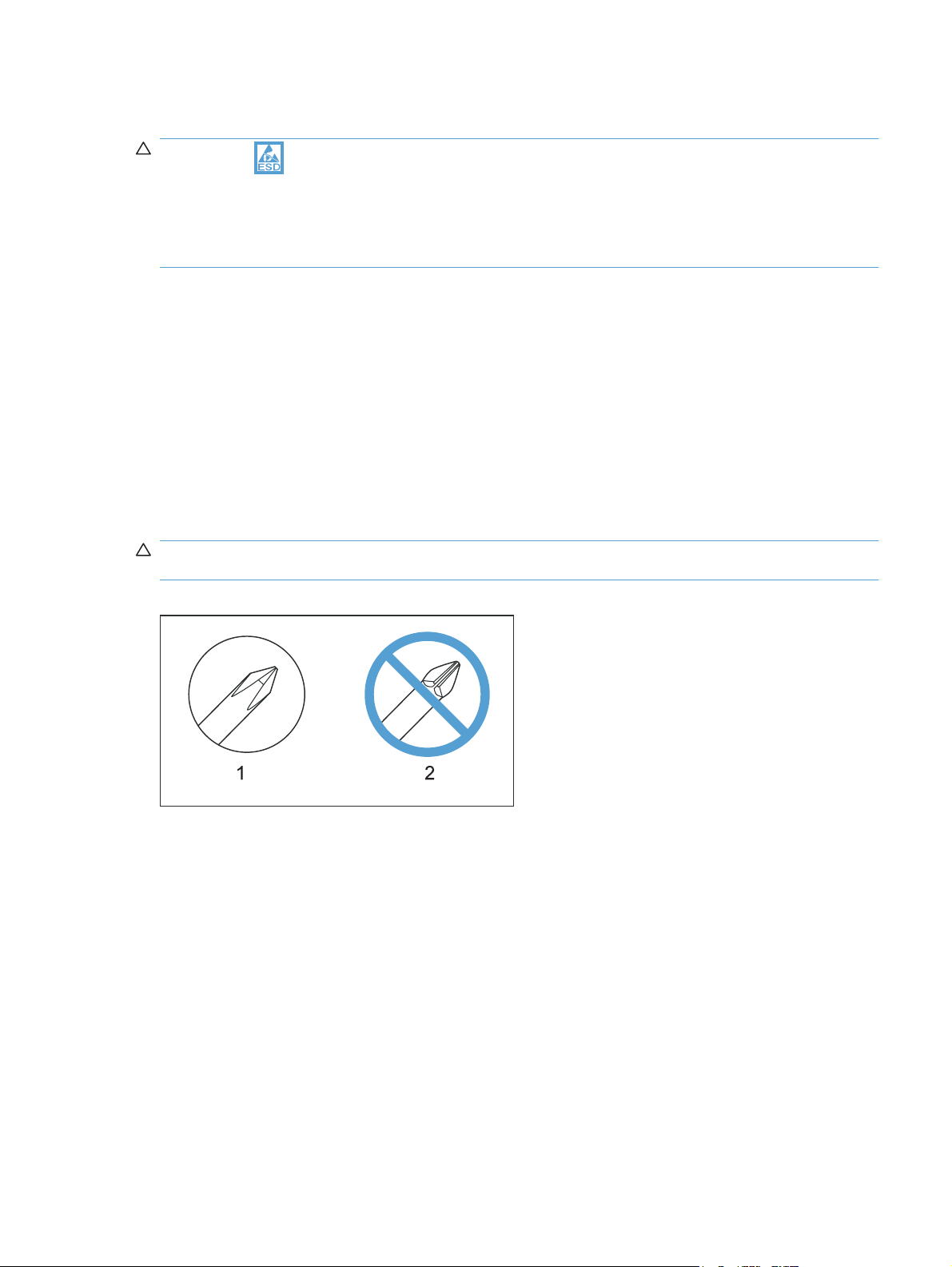
CAUTION: Always use a Phillips screwdriver (callout 1). Do not use a pozidrive screwdriver (callout 2)
or any motorized screwdriver. These can damage screws or screw threads.
Figure 1-1 Phillips and pozidrive screwdriver comparison
ENWW Electrostatic discharge 3
Page 24

Before performing service
CAUTION: Never open the scanner portion of the product unless you are in a clean room environment.
Remove all paper from the product.
●
Turn off the power using the power switch.
●
Unplug the power cable and interface cable or cables.
●
Place the product on an ESD workstation or mat, or use an ESD strap (if one is available). If an
●
ESD workstation, mat, or strap is not available, ground yourself by touching the sheet-metal chassis
before touching an ESD-sensitive part.
Remove the print cartridge.
●
After performing service
Plug in the power cable.
●
Reinstall the print cartridge.
●
Load paper in the product.
●
4 Chapter 1 Removal and replacement ENWW
Page 25

Post-service test
Perform the following test to verify that the repair or replacement was successful.
Print-quality test
1. Verify that you have completed the necessary reassembly steps.
2. Make sure that the tray contains clean, unmarked paper.
3. Attach the power cord and interface cable or interface cables, and then turn on the product.
4. Verify that the expected startup sounds occur.
5. Print a configuration page, and then verify that the expected printing sounds occur.
6. Print a demo page, and then verify that the print quality is as expected.
7. Send a print job from the host computer, and then verify that the output meets expectations.
8. Make a copy from the flatbed glass, and then verify that the output meets expectations.
9. Make a copy from the ADF, and then verify that the output meets expectations (HP LaserJet
Professional M1210 MFP series only).
10. Clean the outside of the product with a damp cloth.
ENWW Post-service test 5
Page 26

Parts removal order
Figure 1-2 Parts removal order; HP LaserJet Professional M1210 MFP series ADF/scanner
Scanner assembly
Automatic document feeder assembly
ADF top cover
ADF pre-pickup arm and roller
ADF core
ADF tray
ADF base
White plate (document backing)
Scanner assembly
Scanner bezel
Scan-drive system
SSA latch
Control panel
Cable, scan module
DC servo motor
1200 PPI scanner assembly
6 Chapter 1 Removal and replacement ENWW
Page 27

Figure 1-3 Parts removal order; HP LaserJet Professional M1130 MFP series scanner
Scanner assembly
Scanner lid
White plate (document backing)
Scanner assembly
Scanner bezel
Scan-drive system
Cable, scan module
DC servo motor
1200 PPI scanner assembly
SSA latch
Control Panel
ENWW Parts removal order 7
Page 28

Figure 1-4 Parts removal order; product base
Print cartridge
Pickup roller & transfer roller
Paper pickup tray & paper delivery tray
Printer side covers
Fax card & fomatter
Cartridge door
Front cover
Top cover
Rear cover
Formatter stay
Separation pad
Fuser
Sensor PCA
Film assembly
Power PCA
Cover, scanner
Laser/scanner assembly
Motor
Motor PCA
8 Chapter 1 Removal and replacement ENWW
Page 29
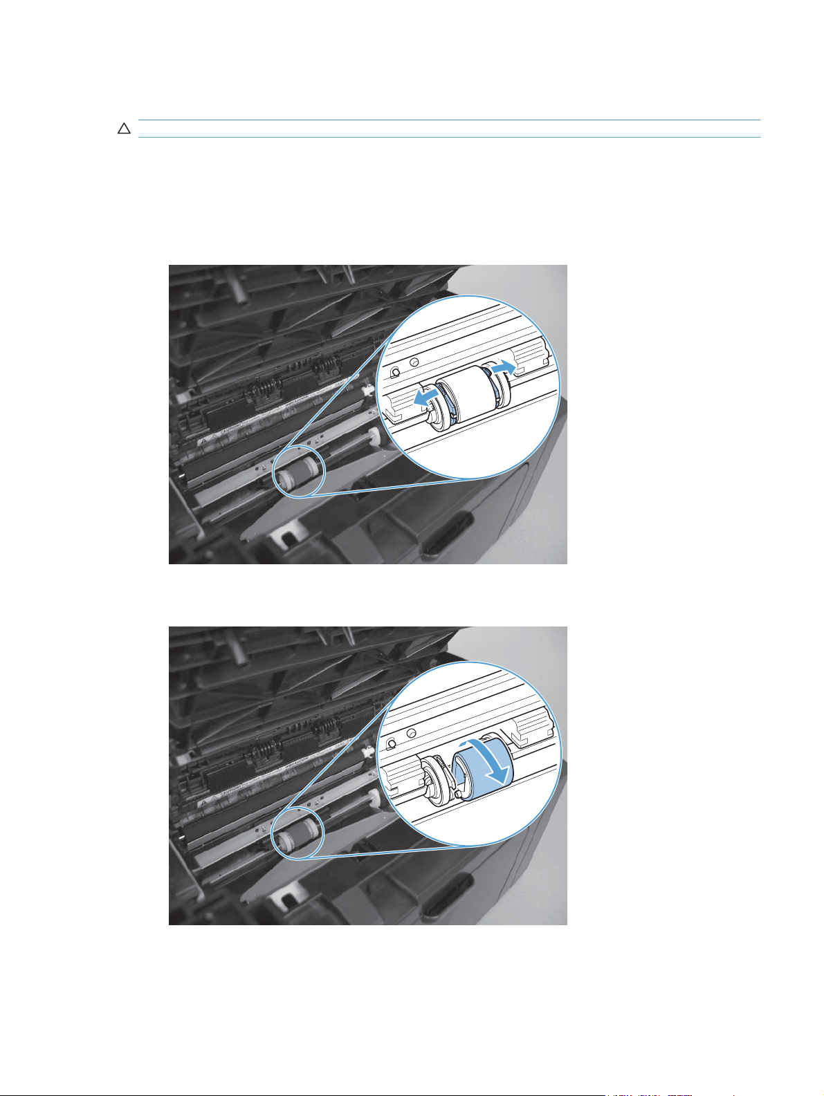
Pickup roller
CAUTION: Do not touch the sponge portion of the roller. Skin oils can cause paper handling problems.
Product base pickup roller
1. Lift the scanner assembly, and open the print-cartridge door.
2. Release two tabs (callout 1).
Figure 1-5 Remove the product base pickup roller (1 of 2)
3. Rotate the roller (callout 2) away from the product to remove it.
Figure 1-6 Remove the product base pickup roller (2 of 2)
ENWW Pickup roller 9
Page 30

ADF pre-pickup arm and pickup roller
NOTE: HP LaserJet Professional M1210 MFP series only
Remove the ADF pre-pickup arm and pickup roller
1. Open the ADF top cover.
Figure 1-7 Remove the ADF pre-pickup arm and pickup roller assembly (1 of 4)
2. Release one tab, and then fully release the ADF top cover.
Figure 1-8 Remove the ADF pre-pickup arm and pickup roller assembly (2 of 4)
10 Chapter 1 Removal and replacement ENWW
Page 31

3. Use a small flat blade screwdriver to release two hinge retainers (callout 1).
CAUTION: The two gears (callout 2) are not captive. Do not lose the gears when removing the
ADF pickup roller assembly.
Reinstallation tip To reinstall the assembly, first position the shaft of the white-plastic gear in
the shaft mounting hole, and then snap the assembly hinge pins into the retainers.
Figure 1-9 Remove the ADF pre-pickup arm and pickup roller assembly (3 of 4)
1 2
4. Release one spring (callout 1), and then remove the assembly.
Figure 1-10 Remove the ADF pre-pickup arm and pickup roller assembly (4 of 4)
1
ENWW Pickup roller 11
Page 32

Reinstall the ADF pre-pickup arm and pickup roller
If the gears become separated from the assembly, use the following figure to correctly reinstall the black(callout 1) and white-plastic drive gears (callout 2).
Figure 1-11 Reinstall the ADF pre-pickup arm and pickup roller assembly gears
2
1
12 Chapter 1 Removal and replacement ENWW
Page 33

Separation pad
CAUTION: Do not touch the sponge portion of the pad. Skin oils can cause paper handling problems.
Before proceeding, remove the following components:
Paper-delivery tray. See
●
Paper-delivery tray (output bin extension) on page 21.
Product base separation pad
1. Place the product rear-side up to access the separation pad assembly.
CAUTION: Dirt and debris can scratch the product covers. Place the product on a cloth or other
clean surface.
2. Remove two screws (callout 1) and then remove the separation pad assembly (callout 2).
Figure 1-12 Remove the product base separation pad assembly
1
2
ENWW Separation pad 13
Page 34

ADF separation pad
NOTE: HP LaserJet Professional M1210 MFP series only
1. Open the ADF top cover.
Figure 1-13 Remove the ADF separation pad assembly (1 of 4)
2. Release one tab, and then fully open the ADF cover.
Figure 1-14 Remove the ADF separation pad assembly (2 of 4)
14 Chapter 1 Removal and replacement ENWW
Page 35

3. Push down on the edges of the assembly, and then move it toward the right side of the product.
Figure 1-15 Remove the ADF separation pad assembly (3 of 4)
1
1
2
4. Remove the assembly.
Figure 1-16 Remove the ADF separation pad assembly (4 of 4)
ENWW Separation pad 15
Page 36

Reinstall the ADF separation pad assembly
1. Position the base of the spring (callout 1) on to the pedestal (callout 2).
Figure 1-17 Reinstall the ADF separation pad assembly (1 of 5)
1
2. Place the assembly hinge pins in the slots in the ADF core.
2
Figure 1-18 Reinstall the ADF separation pad assembly (2 of 5)
16 Chapter 1 Removal and replacement ENWW
Page 37

3. Slightly slide the assembly down and into the slots in the product to engage the hinge pins.
Figure 1-19 Reinstall the ADF separation pad assembly (3 of 5)
4. Locate the upper locking pins.
NOTE: When the assembly is correctly installed, these pins are engage in a slot in the ADF core,
and the spring underneath the assembly keeps the assembly in the raised position.
Figure 1-20 Reinstall the ADF separation pad assembly (4 of 5)
ENWW Separation pad 17
Page 38

5. Push down on the assembly until the pins reach the bottom of the slot in the ADF core, and then
slightly slide the assembly toward the left side of the product to engage the locking pins in the
closed slot. Release the assembly.
CAUTION: The pins on the assembly are fragile and can easily be broken off. Do not force the
assembly into place, or the pins might break.
TIP: You might need to slightly tip the assembly and engage one pin, and then tip the assembly
in the opposite direction to engage the second pin.
Figure 1-21 Reinstall the ADF separation pad assembly (5 of 5)
18 Chapter 1 Removal and replacement ENWW
Page 39

Transfer roller
CAUTION: Do not touch the sponge portion of the roller. Skin oils can cause print quality problems.
1. Open the print-cartridge door.
2. Release two tabs (callout 1), and then remove the transfer roller (callout 2).
Figure 1-22 Remove the transfer roller
2
1
ENWW Transfer roller 19
Page 40

Covers
NOTE: This section includes the trays and the complete scanner assembly.
Paper-pickup tray (input tray)
1. Carefully flex the tray to release two tabs.
Figure 1-23 Remove the paper-pickup tray (1 of 2)
2. Remove the tray.
Figure 1-24 Remove the paper-pickup tray (2 of 2)
20 Chapter 1 Removal and replacement ENWW
Page 41

Paper-delivery tray (output bin extension)
1. Carefully flex the tray to release two tabs.
Figure 1-25 Remove the paper-delivery tray
2. Remove the tray.
Figure 1-26 Remove the paper-pickup tray (2 of 2)
ENWW Covers 21
Page 42

Left cover
Before proceeding, remove the following components:
Paper-delivery tray. See
●
Remove the left cover
1. Remove one screw (callout 1) and then release one tab (callout 3).
NOTE: HP LaserJet Professional M1210 MFP series only: If installed, remove the protective
telephone jack insert (callout 2).
Figure 1-27 Remove the left cover (1 of 6)
Paper-delivery tray (output bin extension) on page 21.
1
3
2
2. Raise the control-panel assembly, and then release one tab at the bottom of the product (callout 1).
Figure 1-28 Remove the left cover (2 of 6)
1
22 Chapter 1 Removal and replacement ENWW
Page 43

3. Raise the scanner assembly.
Figure 1-29 Remove the left cover (3 of 6)
4. Slide the control-panel assembly toward the left cover, and then lift up to slightly raise it.
Figure 1-30 Remove the left cover (4 of 6)
ENWW Covers 23
Page 44

5. Rotate the back of the cover away from the product and down.
TIP: It might be easier to remove the cover, if you let the left side of the product protrude off of
the work surface to give the cover enough clearance to swing down past the bottom of the product.
Figure 1-31 Remove the left cover (5 of 6)
6. Continue to rotate the cover down and away from the product, until the tab (callout 1) located under
the control-panel assembly is released.
Figure 1-32 Remove the left cover (6 of 6)
1
24 Chapter 1 Removal and replacement ENWW
Page 45

Right cover
Before proceeding, remove the following components:
Paper-delivery tray. See
●
Remove the right cover
1. Remove one screw (callout 1).
Figure 1-33 Remove the left cover (1 of 5)
Paper-delivery tray (output bin extension) on page 21.
1
2. Release one tab at the back of the product.
Figure 1-34 Remove the left cover (2 of 5)
ENWW Covers 25
Page 46

3. Release one tab at the bottom of the product.
Figure 1-35 Remove the right cover (3 of 5)
4. Lift the scanner, and slightly rotate the front-lower corner of the cover away from the product.
Figure 1-36 Remove the left cover (4 of 5)
26 Chapter 1 Removal and replacement ENWW
Page 47

5. Rotate the back of the cover down and away from the product to release one tab at the top of the
product, and then remove the cover.
Figure 1-37 Remove the right cover (5 of 5)
ENWW Covers 27
Page 48

Front cover
Before proceeding, remove the following components:
Paper-delivery tray. See
●
Left cover. See
●
Right cover. See
●
Remove the front cover
1. Release one tab (callout 1) at the right side of the product.
Figure 1-38 Remove the front cover (1 of 4)
Paper-delivery tray (output bin extension) on page 21.
Left cover on page 22.
Right cover on page 25.
1
2. Release one tab (callout 1) at the left side of the product.
Figure 1-39 Remove the front cover (2 of 4)
1
28 Chapter 1 Removal and replacement ENWW
Page 49

3. Rotate the bottom of the cover away from the product to release it.
Figure 1-40 Remove the front cover (3 of 4)
4. Remove the cover.
Figure 1-41 Remove the front cover (4 of 4)
ENWW Covers 29
Page 50

Scanner assembly
Before proceeding, remove the following components:
Paper-delivery tray. See
●
Left cover. See
●
Left cover on page 22.
Remove the scanner assembly
1. HP LaserJet Professional M1130 MFP series: Disconnect one FFC (callout 1).
HP LaserJet Professional M1210 MFP series: Disconnect one FFC (callout 1) and one wire
harness connector (callout 2).
Figure 1-42 Remove the scanner assembly (1 of 5; HP LaserJet Professional M1130 MFP series)
Paper-delivery tray (output bin extension) on page 21.
1
Figure 1-43 Remove the scanner assembly (2 of 5; HP LaserJet Professional M1210 MFP series)
2
1
30 Chapter 1 Removal and replacement ENWW
Page 51

2. Support the scanner assembly, and then release one tab (callout 1) and remove the scanner
support (callout 2).
CAUTION: The scanner assembly is not captive and can easily be separated from the product
base if it is opened too far.
Figure 1-44 Remove the scanner assembly (3 of 5)
1
2
3. HP LaserJet Professional M1130 MFP series only: Carefully feed the FFC through the slot in the
chassis (callout 1), and then lift the scanner assembly up and off of the product base.
Figure 1-45 Remove the scanner assembly (4 of 5)
1
ENWW Covers 31
Page 52

4. HP LaserJet Professional M1210 MFP series only: Remove one screw (callout 1), carefully feed
the FFC through the slot in the chassis (callout 2), and then lift the scanner assembly up and off
of the product base.
Figure 1-46 Remove the scanner assembly (5 of 5)
1
2
32 Chapter 1 Removal and replacement ENWW
Page 53

Cartridge door
Before proceeding, remove the following components:
Paper-delivery tray. See
●
Left cover. See
●
Right cover. See
●
Front cover. See
●
Scanner assembly. See
●
Left cover on page 22.
Remove the cartridge door
1. Open the cartridge door. Carefully push up on the right corner of the door to release the right-side
retainer.
CAUTION: The retainer is still attached to the door. This step only releases the door-stop tab of
the retainer.
Reinstallation tip When the door is reinstalled, you must push down on the retainer to reengage
the door-stop tab, or the cartridge door cannot close.
Figure 1-47 Remove the cartridge door (1 of 5)
Paper-delivery tray (output bin extension) on page 21.
Right cover on page 25.
Front cover on page 28.
Scanner assembly on page 30.
ENWW Covers 33
Page 54

2. Carefully push up on the left corner of the door to release the left-side retainer.
CAUTION: The retainer is still attached to the door. This step only releases the door-stop tab of
the retainer.
Reinstallation tip When the door is reinstalled, you must push down on the retainer to reengage
the door-stop tab, or the cartridge door cannot close.
Figure 1-48 Remove the cartridge door (2 of 5)
3. Carefully disengage the both retainers from the door.
Figure 1-49 Remove the cartridge door (3 of 5)
34 Chapter 1 Removal and replacement ENWW
Page 55

4. Use a small flat blade screw driver to release the print-cartridge disengagement arm.
Figure 1-50 Remove the cartridge door (4 of 5)
5. Remove the cartridge door.
Figure 1-51 Remove the cartridge door (5 of 5)
ENWW Covers 35
Page 56

Top cover
Before proceeding, remove the following components:
Paper-delivery tray. See
●
Left cover. See
●
Right cover. See
●
Front cover. See
●
Scanner assembly. See
●
Cartridge door. See
●
Control panel assembly. See
●
TIP: If you are removing the top cover to gain access to other components on the product, you
can leave the control-panel assembly installed on the cover. Disconnect the FFC at the formatter,
and remove the control-panel assembly and the top cover as one unit.
If you are installing a replacement top cover, you must remove the control-panel assembly
completely.
Remove the top cover
1. Remove six screws (callout 1).
Figure 1-52 Remove the top cover (1 of 2)
Paper-delivery tray (output bin extension) on page 21.
Left cover on page 22.
Right cover on page 25.
Front cover on page 28.
Scanner assembly on page 30.
Cartridge door on page 33.
Control-panel assembly on page 62.
1
36 Chapter 1 Removal and replacement ENWW
Page 57

2. Remove the top cover.
Figure 1-53 Remove the top cover (2 of 2)
ENWW Covers 37
Page 58

Rear cover
Before proceeding, remove the following components:
Paper-delivery tray. See
●
Left cover. See
●
Right cover. See
●
Front cover. See
●
Scanner assembly. See
●
Cartridge door . See
●
Top cover. See
●
Remove the rear cover
1. Remove four screws (callout 1) and release two tabs (callout 2).
NOTE: One screw has a tooth washer. Make sure this screw is installed in the correct position
when the cover is reinstalled.
Figure 1-54 Remove the rear cover (1 of 2)
Paper-delivery tray (output bin extension) on page 21.
Left cover on page 22.
Right cover on page 25.
Front cover on page 28.
Scanner assembly on page 30.
Cartridge door on page 33.
Top cover on page 36.
1
2
38 Chapter 1 Removal and replacement ENWW
Page 59

2. Remove the rear cover.
NOTE: When the rear cover is removed, a separate sheet-metal bracket is also removed. Make
sure that the bracket and cover are correctly positioned before the rear cover is reinstalled. See
Reinstall the rear cover on page 40.
Figure 1-55 Remove the rear cover (2 of 2)
ENWW Covers 39
Page 60

Reinstall the rear cover
Make sure that the bracket and cover are correctly positioned before the rear cover is reinstalled
Figure 1-56 Rear cover and bracket correctly positioned
Figure 1-57 Rear cover and bracket incorrectly positioned
40 Chapter 1 Removal and replacement ENWW
Page 61

Scanner components
NOTE: This section describes replacement and removal of individual scanner components. To remove
the complete scanner assembly, see
HP LaserJet Professional M1210 MFP series only: replacement and removal of the ADF pickup roller
and separation pad are described earlier in this chapter. See
on page 10 or ADF separation pad on page 14.
White plate (document backing)
1. Open the scanner lid.
Figure 1-58 Remove the white plate (1 of 3)
Scanner assembly on page 30.
ADF pre-pickup arm and pickup roller
ENWW Scanner components 41
Page 62

2. Use a small flat blade screwdriver to release two tabs (callout 1), and then rotate the top of the
white plate away from the lid.
Figure 1-59 Remove the white plate (2 of 3)
1
3. Remove the white plate.
Figure 1-60 Remove the white plate (3 of 3)
42 Chapter 1 Removal and replacement ENWW
Page 63

ADF top cover
NOTE: HP LaserJet Professional M1210 MFP series only.
1. Open the ADF top cover.
Figure 1-61 Remove the ADF top cover (1 of 4)
2. Release one tab, and then fully open the ADF cover.
Figure 1-62 Remove the ADF top cover (2 of 4)
ENWW Scanner components 43
Page 64

3. Use a small flat blade screwdriver to release one hinge pin (callout 1).
Figure 1-63 Remove the ADF top cover (3 of 4)
1
4. Slide the cover toward the rear of the ADF to release the rear hinge pin, and then lift up to remove
the cover.
Figure 1-64 Remove the ADF top cover (4 of 4)
44 Chapter 1 Removal and replacement ENWW
Page 65

ADF core
NOTE: HP LaserJet Professional M1210 MFP series only.
Before proceeding, remove the following components:
Paper-delivery tray. See
●
Scanner assembly. See
●
ADF top cover. See
●
Remove the ADF core
1. Carefully feed the wire harness (callout 1) through the slot in the ADF chassis (callout 2).
Figure 1-65 Remove the ADF core (1 of 5)
Paper-delivery tray (output bin extension) on page 21.
Scanner assembly on page 30.
ADF top cover on page 43.
2
1
ENWW Scanner components 45
Page 66

2. Open the scanner lid, and carefully feed the wire harness (callout 1) through the opening (callout 2)
in the chassis.
Figure 1-66 Remove the ADF core (2 of 5)
1
2
3. Close the scanner lid, and release the wire harness (callout 1) from the guides (callout 2).
Figure 1-67 Remove the ADF core (3 of 5)
1
2
46 Chapter 1 Removal and replacement ENWW
Page 67

4. Open the ADF core, and then flex the chassis to release one hinge pin (callout 1).
Figure 1-68 Remove the ADF core (4 of 5)
1
5. Slide the core toward the rear of the ADF to release the rear hinge pin, and then remove the core.
Figure 1-69 Remove the ADF core (5 of 5)
ENWW Scanner components 47
Page 68

ADF tray
NOTE: HP LaserJet Professional M1210 MFP series only.
Before proceeding, remove the following components:
Paper-delivery tray. See
●
Scanner assembly. See
●
ADF top cover. See
●
ADF core. See
●
Remove the ADF tray
1. Remove two screws (callout 1).
CAUTION: The spring-latch clips (callout 1) are not captive. Do not lose the clips when removing
the tray.
Figure 1-70 Remove the ADF tray (1 of 4)
Paper-delivery tray (output bin extension) on page 21.
Scanner assembly on page 30.
ADF top cover on page 43.
ADF core on page 45.
1
48 Chapter 1 Removal and replacement ENWW
Page 69

2. Carefully flex the tray to release one tab (callout 1), and then slightly rotate the edge of the tray up
and away from the ADF.
Figure 1-71 Remove the ADF tray (2 of 4)
1
3. Continue to rotate the tray up and off of the product to release one tab (callout 1).
Figure 1-72 Remove the ADF tray (3 of 4)
1
ENWW Scanner components 49
Page 70

4. Remove the tray.
Figure 1-73 Remove the ADF tray (4 of 4)
50 Chapter 1 Removal and replacement ENWW
Page 71

ADF base or scanner assembly lid
NOTE: For the HP LaserJet Professional M1130 MFP series, use this procedure to remove the
scanner assembly lid (see to step 1 below).
For the HP LaserJet Professional M1210 MFP series, use this procedure to remove the ADF base.
Before proceeding, remove the following components:
Paper-delivery tray. See
●
Scanner assembly (HP LaserJet Professional M1210 MFP series only). See
●
on page 30.
ADF top cover (HP LaserJet Professional M1210 MFP series only). See
●
on page 43.
ADF core (HP LaserJet Professional M1210 MFP series only). See
●
ADF tray (HP LaserJet Professional M1210 MFP series only). See
●
Paper-delivery tray (output bin extension) on page 21.
Remove the ADF base or scanner assembly lid
1. Open the ADF base or scanner assembly lid.
Figure 1-74 Remove the ADF base or scanner assembly lid (1 of 3)
Scanner assembly
ADF top cover
ADF core on page 45.
ADF tray on page 48.
ENWW Scanner components 51
Page 72

2. Carefully flex the base or lid to release two tabs (callout 1).
Figure 1-75 Remove the ADF base or scanner assembly lid (2 of 3)
1
3. Push the base or lid away from the scanner assembly to remove it.
Figure 1-76 Remove the ADF base or scanner assembly lid (3 of 3)
52 Chapter 1 Removal and replacement ENWW
Page 73

Scanner assembly bezel
Before proceeding, remove the following components:
Paper-delivery tray. See
●
Scanner assembly (HP LaserJet Professional M1210 MFP series only). See
●
on page 30.
ADF top cover (HP LaserJet Professional M1210 MFP series only). See
●
on page 43.
ADF core (HP LaserJet Professional M1210 MFP series only). See
●
ADF tray (HP LaserJet Professional M1210 MFP series only). See
●
ADF base or scanner assembly lid. See
●
Paper-delivery tray (output bin extension) on page 21.
Remove the scanner assembly bezel
CAUTION: The components inside of the scanner assembly are not captive when the bezel is
removed.
Remove six screws (callout 1), and then remove the bezel.
Figure 1-77 Remove the scanner assembly bezel (1 of 2; HP LaserJet Professional M1130 MFP series)
Scanner assembly
ADF top cover
ADF core on page 45.
ADF tray on page 48.
ADF base or scanner assembly lid on page 51.
1
ENWW Scanner components 53
Page 74

Figure 1-78 Remove the scanner assembly bezel (2 of 2; HP LaserJet Professional M1210 MFP series)
1
54 Chapter 1 Removal and replacement ENWW
Page 75

Scanner assembly latch
NOTE: HP LaserJet Professional M1210 MFP series only.
Paper-delivery tray. See
●
Scanner assembly. See
●
ADF top cover. See
●
ADF core. See
●
ADF tray. See
●
ADF base. See
●
Scanner assembly bezel. See
●
ADF core on page 45.
ADF tray on page 48.
ADF base or scanner assembly lid on page 51.
Paper-delivery tray (output bin extension) on page 21.
Scanner assembly on page 30.
ADF top cover on page 43.
Remove the scanner assembly latch
Remove the latch and spring (callout 1).
Figure 1-79 Remove the scanner assembly latch
Scanner assembly bezel on page 53.
1
ENWW Scanner components 55
Page 76

CIS scanner-carriage assembly
Before proceeding, remove the following components:
Paper-delivery tray. See
●
Scanner assembly. See
●
ADF top cover (HP LaserJet Professional M1210 MFP series only). See
●
on page 43.
ADF core (HP LaserJet Professional M1210 MFP series only). See
●
ADF tray (HP LaserJet Professional M1210 MFP series only). See
●
ADF base or scanner assembly lid. See
●
Scanner assembly bezel. See
●
Paper-delivery tray (output bin extension) on page 21.
Scanner assembly on page 30.
Scanner assembly bezel on page 53.
Remove the CIS scanner-carriage assembly
1. Lift the CIS scanner-carriage assembly (callout 1) out of the scanner.
CAUTION: The CIS scanner-carriage assembly is still connected to the scanner assembly by the
FFC.
Figure 1-80 Remove the CIS scanner-carriage assembly (1 of 2)
ADF top cover
ADF core on page 45.
ADF tray on page 48.
ADF base or scanner assembly lid on page 51.
1
56 Chapter 1 Removal and replacement ENWW
Page 77

2. Disconnect two FFCs (callout 1) and then remove the CIS scanner assembly.
NOTE: HP LaserJet Professional M1210 MFP series shown below.
Figure 1-81 Remove the CIS scanner-carriage assembly (2 of 2)
1
ENWW Scanner components 57
Page 78

CIS scanner motor, gears, and scanner light bar
Before proceeding, remove the following components:
Paper-delivery tray. See
●
Scanner assembly. See
●
ADF top cover (HP LaserJet Professional M1210 MFP series only). See
●
on page 43.
ADF core (HP LaserJet Professional M1210 MFP series only). See
●
ADF tray (HP LaserJet Professional M1210 MFP series only). See
●
ADF base or scanner assembly lid. See
●
Scanner assembly bezel. See
●
Paper-delivery tray (output bin extension) on page 21.
Scanner assembly on page 30.
ADF base or scanner assembly lid on page 51.
Scanner assembly bezel on page 53.
Remove the CIS scanner motor, gears, and scanner light bar
The HP LaserJet Professional M1210 MFP series CIS scanner assembly is shown in the figures below.
1. Turn the CIS scanner upside down to expose the motor and gears.
Figure 1-82 Remove the CIS scanner motor, gears, and scanner light bar (1 of 4)
ADF top cover
ADF core on page 45.
ADF tray on page 48.
58 Chapter 1 Removal and replacement ENWW
Page 79

2. Disconnect two connectors (callout 1).
Figure 1-83 Remove the CIS scanner motor, gears, and scanner light bar (2 of 4)
1
3. Remove two screws (callout 1), remove the sheet-metal plate (callout 2), and then remove the
motor and two gears (callout 3).
Figure 1-84 Remove the CIS scanner motor, gears, and scanner light bar (3 of 4)
1
2
3
ENWW Scanner components 59
Page 80

4. Remove one screw (callout 1), and then separate the scanner light bar (callout 2) from the carriage
assembly (callout 3).
Figure 1-85 Remove the CIS scanner motor, gears, and scanner light bar (4 of 4)
1
2
3
60 Chapter 1 Removal and replacement ENWW
Page 81

CIS scanner drive gears
NOTE: HP LaserJet Professional M1210 MFP series only.
Before proceeding, remove the following components:
Paper-delivery tray. See
●
Scanner assembly. See
●
ADF top cover. See
●
ADF core. See
●
ADF tray. See
●
ADF base. See
●
Scanner assembly bezel. See
●
ADF core on page 45.
ADF tray on page 48.
ADF base or scanner assembly lid on page 51.
Paper-delivery tray (output bin extension) on page 21.
Scanner assembly on page 30.
ADF top cover on page 43.
Remove the CIS scanner drive gears
1. Move the CIS scanner out of the way to expose the drive gears.
2. Remove one screw (callout 1), and then remove three gears (callout 2).
Figure 1-86 Remove the CIS scanner motor and gears
1
Scanner assembly bezel on page 53.
2
ENWW Scanner components 61
Page 82

Main assemblies
Control-panel assembly
Before proceeding, remove the following components:
Paper-delivery tray. See
●
Left cover. See
●
Left cover on page 22.
Paper-delivery tray (output bin extension) on page 21.
Remove the control-panel assembly
1. Disconnect one FFC (callout 1).
Figure 1-87 Remove the control-panel assembly (1 of 5; HP LaserJet Professional M1130 MFP
series)
1
Figure 1-88 Remove the control-panel assembly (2 of 5; HP LaserJet Professional M1210 MFP
series)
1
62 Chapter 1 Removal and replacement ENWW
Page 83

2. Remove two screws (callout 1), and then remove the assembly (callout 2).
Figure 1-89 Remove the control-panel assembly (3 of 5)
1
2
3. Slide the assembly toward the left and then lift up on it to release the ratchet arm.
Figure 1-90 Remove the control-panel assembly (4 of 5)
ENWW Main assemblies 63
Page 84

4. Continue to slide the assembly to release it from the bracket.
Figure 1-91 Remove the control-panel assembly (5 of 5)
Reinstall the control-panel assembly
1. Remove one spring (callout 1), and install it in the replacement control-panel assembly.
Figure 1-92 Reinstall the control-panel assembly (1 of 2)
1
64 Chapter 1 Removal and replacement ENWW
Page 85

2. Make sure that the ferrite is correctly positioned in the holder.
NOTE: Two sided-tape is provided on the FFC to adhere it to the chassis as needed
Figure 1-93 Reinstall the control-panel assembly (2 of 2)
ENWW Main assemblies 65
Page 86

Power switch assembly
Before proceeding, remove the following components:
Paper-delivery tray. See
●
Left cover. See
●
Left cover on page 22.
Paper-delivery tray (output bin extension) on page 21.
Remove the power switch assembly
1. Disconnect one connector (callout 1).
Figure 1-94 Remove the power switch assembly (1 of 3)
1
2. Release one tab (callout 1), and then slide the assembly up and away from the product to release
it.
Figure 1-95 Remove the power switch assembly (2 of 3)
1
66 Chapter 1 Removal and replacement ENWW
Page 87

3. Remove the power switch assembly.
Figure 1-96 Remove the power switch assembly (3 of 3)
ENWW Main assemblies 67
Page 88

Formatter PCA
Before proceeding, remove the following components:
Paper-delivery tray. See
●
Left cover. See
●
Left cover on page 22.
Remove the formatter PCA
1. HP LaserJet Professional M1130 MFP series: Disconnect three FFCs (callout 1) and one wire
harness connector (callout 2).
HP LaserJet Professional M1210 MFP series: Disconnect four FFCs (callout 1) and two wire
harness connector (callout 2).
Figure 1-97 Remove the formatter PCA (1 of 4; HP LaserJet Professional M1130 MFP series)
Paper-delivery tray (output bin extension) on page 21.
2
1
Figure 1-98 Remove the formatter PCA (2 of 4; HP LaserJet Professional M1210 MFP series)
2
1
68 Chapter 1 Removal and replacement ENWW
Page 89

2. HP LaserJet Professional M1130 MFP series: Remove four screws (callout 1), and then remove
the PCA.
HP LaserJet Professional M1210 MFP series: Remove six screws (callout 1), and then remove
the PCA.
Figure 1-99 Remove the formatter PCA (3 of 4; HP LaserJet Professional M1130 MFP series)
1
Figure 1-100 Remove the formatter PCA (4 of 4; HP LaserJet Professional M1210 MFP series)
1
ENWW Main assemblies 69
Page 90

Fax PCA
NOTE: HP LaserJet Professional M1210 MFP series only.
Before proceeding, remove the following components:
Paper-delivery tray. See
●
Left cover. See
●
Remove the Fax PCA
Disconnect one FFC (callout 1), remove three screws (callout 2), and then remove the PCA.
Figure 1-101 Remove the Fax PCA
Paper-delivery tray (output bin extension) on page 21.
Left cover on page 22.
2
1
70 Chapter 1 Removal and replacement ENWW
Page 91

Laser/scanner assembly
Before proceeding, remove the following components:
Paper-delivery tray. See
●
Left cover. See
●
Right cover. See
●
Front cover. See
●
Scanner assembly. See
●
Cartridge door. See
●
Top cover. See
●
Left cover on page 22.
Right cover on page 25.
Front cover on page 28.
Top cover on page 36.
Paper-delivery tray (output bin extension) on page 21.
Scanner assembly on page 30.
Cartridge door on page 33.
Remove the laser/scanner assembly
1. Release one tab (callout 1), and then remove the holder (callout 2).
Figure 1-102 Remove the laser/scanner assembly (1 of 3)
2
1
ENWW Main assemblies 71
Page 92

2. Remove four screws (callout 1), the scanner cover (callout 2) and the sheet-metal plate (callout 3).
NOTE: The scanner cover and plate are removed as one assembly.
Figure 1-103 Remove the laser/scanner assembly (2 of 3)
1
2
3
3. Disconnect one FFC (callout 1), remove four screws (callout 2), disconnect one connector (callout
3), and then remove the laser/scanner assembly.
Figure 1-104 Remove the laser/scanner assembly (3 of 3)
1
2
3
72 Chapter 1 Removal and replacement ENWW
Page 93

Reinstall the laser/scanner assembly
When the holder is reinstalled (callout 1), make sure that the lever arm (callout 2) is correctly
▲
positioned.
Figure 1-105 Reinstall the laser/scanner assembly
1
2
ENWW Main assemblies 73
Page 94

Main motor
Before proceeding, remove the following components:
Paper-delivery tray. See
●
Left cover. See
●
Right cover. See
●
Front cover. See
●
Remove the main motor
1. Release one tab (callout 1), and then remove the holder (callout 2).
Figure 1-106 Remove the laser/scanner assembly (1 of 7)
Paper-delivery tray (output bin extension) on page 21.
Left cover on page 22.
Right cover on page 25.
Front cover on page 28.
1
2
74 Chapter 1 Removal and replacement ENWW
Page 95

2. Remove four screws (callout 1), the scanner cover (callout 2) and the sheet-metal plate (callout 3).
NOTE: The scanner cover and plate can be removed as one assembly.
Figure 1-107 Remove the laser/scanner assembly (2 of 7)
1
2
3
3. Release two tabs (callout 1), and then slightly separate the motor driver PCA (callout 2) from the
product.
CAUTION: The motor driver PCA is still connected to the product by the wire harnesses and a
FFC.
Figure 1-108 Remove the main motor (3 of 7)
1
2
ENWW Main assemblies 75
Page 96

4. Disconnect one connector (callout 1) and carefully set the PCA out of the way.
CAUTION: The motor driver PCA is still connected to the product by the FFC.
Figure 1-109 Remove the main motor (4 of 7)
1
5. Release the wire harness (callout 1) from the guide (callout 2), remove one screw (callout 3), and
then remove the cover (callout 4).
Figure 1-110 Remove the main motor (5 of 7)
3
2
1
4
76 Chapter 1 Removal and replacement ENWW
Page 97

6. Remove two screws (callout 1).
Figure 1-111 Remove the main motor (6 of 7)
7. Remove the main motor.
Figure 1-112 Remove the main motor (7 of 7)
1
ENWW Main assemblies 77
Page 98

Reinstall the main-motor drive belt
When the main motor is reinstalled, make sure that the drive belt (callout 1) is correctly positioned
▲
over the roller (callout 2).
Figure 1-113 Main-motor drive belt: correctly installed
2
Figure 1-114 Main-motor drive belt: incorrectly installed
1
2
1
78 Chapter 1 Removal and replacement ENWW
Page 99

Fuser
Before proceeding, remove the following components:
Paper-delivery tray. See
●
Left cover. See
●
Right cover. See
●
Front cover. See
●
Scanner assembly. See
●
Cartridge door. See
●
Top cover. See
●
Rear cover. See
●
Formatter PCA, primary. See
●
Fax PCA (HP LaserJet Professional M1210 MFP series only). See
●
Remove the fuser
1. Disconnect one connector (callout 1), remove five screws ( callout 2), and then remove the sheet-
metal formatter stay (callout 3).
NOTE: One screw has a flat washer and lock washer. Make sure that this screw is correctly
positioned when the assembly is reinstalled.
Paper-delivery tray (output bin extension) on page 21.
Left cover on page 22.
Right cover on page 25.
Front cover on page 28.
Scanner assembly on page 30.
Cartridge door on page 33
Top cover on page 36.
Rear cover on page 38.
Formatter PCA on page 68.
Fax PCA on page 70.
Figure 1-115 Remove the fuser (1 of 6)
2
3
1
ENWW Main assemblies 79
Page 100

2. Remove the black-plastic engine-controller-PCA stay (callout 1).
Figure 1-116 Remove the fuser (2 of 6)
1
3. Disconnect one connector (callout 1), and then remove the wire harness (callout 2) from the guide
(callout 3).
Figure 1-117 Remove the fuser (3 of 6)
2
3
1
80 Chapter 1 Removal and replacement ENWW
 Loading...