

Page 1
HP LaserJet M1005 MFP
Service Manual
Page 2

Page 3

HP LaserJet M1005 MFP
Service Manual
Page 4

Copyright and License
Trademark credits
© 2006 Copyright Hewlett-Packard
Development Company, L.P.
Reproduction, adaptation, or translation
without prior written permission is prohibited,
except as allowed under the copyright laws.
The information contained in this document
is subject to change without notice.
The only warranties for HP products and
services are set forth in the express warranty
statements accompanying such products
and services. Nothing herein should be
construed as constituting an additional
warranty. HP shall not be liable for technical
or editorial errors or omissions contained
herein.
Part number CB376-90929
Edition 1, 8/2006
Microsoft®, Windows®, and Windows NT®
are U.S. registered trademarks of Microsoft
Corporation.
Linux is a U.S. registered trademark of Linus
Torvalds.
PostScript® is a trademarks of Adobe
Systems Incorporated.
UNIX® is a registered trademark of The
Open Group.
Energy Star® and the Energy Star® logo are
U.S. registered marks of the United States
Environmental Protection Agency.
Page 5

Table of contents
1 Device information
Quick access to device information ...................................................................................................... 2
Model and serial number label ............................................................................................................. 3
Features at a glance ............................................................................................................................. 4
Walkaround .......................................................................................................................................... 5
General guidelines ............................................................................................................................... 6
Choosing paper and other media ......................................................................................................... 6
HP media ............................................................................................................................. 6
Media to avoid ..................................................................................................................... 6
Media that can damage the device ...................................................................................... 7
Guidelines for using media ................................................................................................................... 8
Paper ................................................................................................................................... 8
Colored paper ...................................................................................................................... 9
Custom-size media .............................................................................................................. 9
Labels .................................................................................................................................. 9
Label construction ............................................................................................... 9
Transparencies .................................................................................................................... 9
Envelopes .......................................................................................................................... 10
Envelope construction ....................................................................................... 10
Envelopes with double-side seams ................................................................... 10
Envelopes with adhesive strips or flaps ............................................................ 11
Envelope storage .............................................................................................. 11
Card stock and heavy media ............................................................................................. 11
Card stock construction ..................................................................................... 11
Card stock guidelines ........................................................................................ 11
Letterhead and preprinted forms ....................................................................................... 12
Supported media weights and sizes ................................................................................................... 13
Printing and storage environment ...................................................................................................... 14
2 Installation
What is in the box ............................................................................................................................... 16
Site requirements ............................................................................................................................... 17
Physical specifications ....................................................................................................... 17
Space requirements ........................................................................................................... 17
Loading media .................................................................................................................................... 18
Loading documents to copy or scan .................................................................................. 18
Loading input trays ............................................................................................................ 18
Main input tray (tray 1) ...................................................................................... 18
Priority input tray ............................................................................................... 19
ENWW iii
Page 6

Connect power ................................................................................................................................... 20
Minimum system requirements .......................................................................................................... 21
Supported operating systems ............................................................................................................. 21
Software installation ........................................................................................................................... 22
Printer driver ....................................................................................................................................... 23
Printer-driver Help .............................................................................................................. 23
Changing printer-driver settings ......................................................................................... 24
Software for Windows ........................................................................................................................ 25
HP LaserJet Scan software ............................................................................................... 25
Installing Windows device software ................................................................................... 25
Uninstalling Windows device software ............................................................................... 25
Uninstalling Macintosh device software ............................................................................. 25
3 Managing the device
Control panel ...................................................................................................................................... 28
Information pages ............................................................................................................................... 29
Managing supplies ............................................................................................................................. 30
Checking supplies status ................................................................................................... 30
Storing supplies ................................................................................................................. 30
Replacing and recycling supplies ...................................................................................... 30
HP policy on non-HP supplies ........................................................................................... 30
HP fraud hotline ................................................................................................................. 31
Supplies .............................................................................................................................................. 32
Cable and interface accessories ........................................................................................................ 32
User-replaceable parts ....................................................................................................................... 32
Paper and other print media ............................................................................................................... 32
4 Maintenance
Cleaning the device ............................................................................................................................ 36
To clean the exterior .......................................................................................................... 36
To clean the scanner glass ................................................................................................ 36
To clean the lid backing ..................................................................................................... 36
To clean the paper path ..................................................................................................... 37
Print cartridge ..................................................................................................................................... 38
Approximate print-cartridge replacement intervals ............................................................ 38
Managing the print cartridge .............................................................................................. 38
Replacing supplies and parts ............................................................................................................. 40
Supply replacement guidelines .......................................................................................... 40
Changing the print cartridge .............................................................................................. 40
5 Theory of Operation
Basic functions ................................................................................................................................... 44
Basic sequence of operation .............................................................................................................. 45
Formatter system ............................................................................................................................... 46
Central processing unit ...................................................................................................... 46
Print-cartridge life expectancy ........................................................................... 38
Print-cartridge storage ....................................................................................... 38
HP policy on non-HP print cartridges ................................................................ 38
HP fraud hotline ................................................................................................ 38
iv ENWW
Page 7

Standard boot process ....................................................................................................... 46
Device startup messages .................................................................................. 46
RAM ................................................................................................................................... 47
Universal serial bus (USB) interface .................................................................................. 47
Control panel ..................................................................................................................... 47
EconoMode ........................................................................................................................ 47
Device functions ................................................................................................................................. 48
Engine control system (engine control unit and power-supply assembly) ......................... 48
Device engine control system ........................................................................... 49
Device laser/scanner unit ................................................................................. 49
Power system on the power-supply assembly .................................................. 49
Image-formation system .................................................................................................... 51
The seven image-formation processes ............................................................ 52
Print cartridge .................................................................................................................... 53
Device paper-feed system ................................................................................................. 53
Jam detection in the device ............................................................................................... 54
Conditions of jam detection ............................................................................... 54
HP LaserJet M1005 MFP unique components ................................................................................... 56
Scanner functions and operation ....................................................................................... 56
Scanner functions ............................................................................................ 56
Scanner operation ............................................................................................. 57
6 Removal and replacement
Removal and replacement strategy .................................................................................................... 60
Admonitions ....................................................................................................................... 60
Required tools .................................................................................................................... 60
Before performing service .................................................................................................. 61
After performing service ..................................................................................................... 61
Parts removal order ........................................................................................................... 61
Flatbed lid .......................................................................................................................... 63
Control-panel overlay ......................................................................................................... 64
Control panel ..................................................................................................................... 65
Scanner assembly ............................................................................................................. 67
Device separation pad ....................................................................................................... 73
Print cartridge .................................................................................................................... 74
Device pickup roller ........................................................................................................... 75
Media input tray ................................................................................................................. 78
Transfer roller .................................................................................................................... 80
Device side covers ............................................................................................................. 82
Print-cartridge door ............................................................................................................ 85
Rear cover and fuser cover ............................................................................................... 86
Front cover ......................................................................................................................... 88
Installing the scanner cushions .......................................................................................... 90
Power supply ..................................................................................................................... 91
Formatter ........................................................................................................................... 94
Scanner support frame ..................................................................................................... 95
Engine controller unit ......................................................................................................... 98
Laser/scanner assembly .................................................................................................. 102
Main motor ....................................................................................................................... 103
Fuser ................................................................................................................................ 105
ENWW v
Page 8

7 Troubleshooting
Basic troubleshooting ....................................................................................................................... 110
Control-panel messages .................................................................................................................. 113
Solving image-quality problems ....................................................................................................... 116
Solving scanning (copying) image-quality problems ........................................................................ 124
Repetitive image defect ruler ............................................................................................................ 130
Solving paper-feed problems ........................................................................................................... 131
Functional checks ............................................................................................................................. 135
Firmware update using a flash executable file ................................................................................. 139
Troubleshooting tools ....................................................................................................................... 140
Service-mode functions .................................................................................................................... 141
Main wiring ....................................................................................................................................... 146
Component locations ........................................................................................................................ 148
Paper-pickup assembly ................................................................................................... 107
Alert and warning messages .......................................................................................... 113
Critical error messages ................................................................................................... 113
Event-log codes ............................................................................................................... 115
Checking the print cartridge ............................................................................................ 116
To redistribute the toner in the print cartridge ................................................. 116
Solving print image-quality problems ............................................................................... 116
Print image-quality problems ........................................................................... 116
Scanning (copying) image-quality problems .................................................................... 124
Jams occur in the device ................................................................................................. 131
To clear a jam ................................................................................................. 131
Solving print paper-feed problems ................................................................................... 132
Print paper-feed problems ............................................................................... 133
Half self-test functional check ......................................................................................... 135
To perform a half self-test check ..................................................................... 135
To perform other checks ................................................................................. 135
Drum rotation functional check ........................................................................................ 136
High-voltage contacts check ............................................................................................ 137
To check the print-cartridge contacts .............................................................. 137
To check the high-voltage connector pins ....................................................... 138
Printing a configuration report, demonstration page, or menu structure .......................... 140
Secondary service menu ................................................................................................. 141
To gain access to the secondary service menu .............................................. 141
Adjusting the country/region code parameters ................................................................ 142
To change the country/region from one location to another ............................ 142
To set the language and location if none is set ............................................... 142
NVRAM init ...................................................................................................................... 142
To perform NVRAM init ................................................................................... 143
System settings for localized products ............................................................................ 143
8 Parts and diagrams
Ordering parts and supplies ............................................................................................................. 152
Parts that wear ................................................................................................................ 152
Parts ................................................................................................................................ 152
World-wide customer support .......................................................................................... 152
Accessories ...................................................................................................................................... 153
vi ENWW
Page 9

Common hardware .......................................................................................................... 153
How to use the parts lists and diagrams .......................................................................... 154
Scanner assembly ............................................................................................................................ 156
Formatter .......................................................................................................................................... 158
Whole unit replacement part ............................................................................................................ 160
Alphabetical parts list ....................................................................................................................... 176
Numerical parts list ........................................................................................................................... 180
Appendix A Device specifications
Physical specifications ..................................................................................................................... 186
Electrical specifications .................................................................................................................... 186
Power consumption .......................................................................................................................... 186
Environmental specifications ............................................................................................................ 186
Acoustic emissions ........................................................................................................................... 187
Appendix B Product warranty
Hewlett-Packard Limited Warranty Statement ................................................................................. 190
Availability of support and service .................................................................................................... 191
HP maintenance agreements ........................................................................................................... 192
Next-Day Onsite Service ................................................................................................. 192
Appendix C Regulatory information
FCC compliance ............................................................................................................................... 194
Declaration of conformity ................................................................................................................. 195
Country-/region-specific safety statements ...................................................................................... 196
Laser safety statement .................................................................................................... 196
Canadian DOC statement ................................................................................................ 196
Korean EMI statement ..................................................................................................... 196
Finnish laser statement .................................................................................................... 197
Index ................................................................................................................................................................. 199
ENWW vii
Page 10

viii ENWW
Page 11

List of tables
Table 1-1 Device guides ..................................................................................................................................... 2
Table 1-2 Features ............................................................................................................................................. 4
Table 1-3 Priority input tray specifications ........................................................................................................ 13
Table 1-4 Tray 1 specifications ........................................................................................................................ 13
Table 2-1 Physical dimensions for the HP LaserJet M1005 MFP .................................................................... 17
Table 5-1 HP LaserJet M1005 MFP ................................................................................................................. 45
Table 5-2 Device startup messages ................................................................................................................. 46
Table 5-3 Dc power distribution ........................................................................................................................ 49
Table 7-1 Event-log codes ............................................................................................................................. 115
Table 7-2 System settings .............................................................................................................................. 143
Table 8-1 Technical support websites and related documentation ................................................................ 152
Table 8-2 Accessories .................................................................................................................................... 153
Table 8-3 Common fasteners ........................................................................................................................ 153
Table 8-4 Scanner assembly .......................................................................................................................... 157
Table 8-5 Formatter ........................................................................................................................................ 159
Table 8-6 Whole unit replacement part .......................................................................................................... 161
Table 8-7 Pickup- and delivery- tray assemblies ............................................................................................ 163
Table 8-8 External covers .............................................................................................................................. 165
Table 8-9 Internal components (1 of 3) .......................................................................................................... 167
Table 8-10 Internal components (2 of 3) ........................................................................................................ 169
Table 8-11 Internal components (3 of 3) ........................................................................................................ 171
Table 8-12 Paper-pickup assembly ................................................................................................................ 173
Table 8-13 Fuser (fixing assy) assembly ........................................................................................................ 175
Table 8-14 Alphabetical parts list ................................................................................................................... 176
Table 8-15 Numerical parts list ....................................................................................................................... 180
Table A-1 Physical specifications ................................................................................................................... 186
Table A-2 Electrical specifications .................................................................................................................. 186
Table A-3 Power consumption (average, in watts), ...................................................................................... 186
Table A-4 Environmental specifications ........................................................................................................ 186
Table A-5 Acoustic emissions , ...................................................................................................................... 187
ENWW ix
Page 12

x ENWW
Page 13

List of figures
Figure 1-1 Model and serial number label .......................................................................................................... 3
Figure 1-2 Front view ......................................................................................................................................... 5
Figure 1-3 Back view .......................................................................................................................................... 5
Figure 2-1 What is in the shipping box ............................................................................................................. 16
Figure 2-2 Space requirements ........................................................................................................................ 17
Figure 2-3 Loading documents to copy or scan ............................................................................................... 18
Figure 2-4 Loading the main input tray (tray 1) (1 of 2) .................................................................................... 18
Figure 2-5 Loading the main input tray (tray 1) (2 of 2) .................................................................................... 19
Figure 2-6 Loading the priority input tray (1 of 2) ............................................................................................. 19
Figure 2-7 Loading the priority input tray (2 of 2) ............................................................................................. 19
Figure 2-8 Connect power ................................................................................................................................ 20
Figure 3-1 Control panel ................................................................................................................................... 28
Figure 4-1 Cleaning the scanner glass ............................................................................................................ 36
Figure 4-2 Cleaning the lid backing .................................................................................................................. 37
Figure 4-3 Changing the print cartridge (1 of 5) ............................................................................................... 40
Figure 4-4 Changing the print cartridge (2 of 5) ............................................................................................... 40
Figure 4-5 Changing the print cartridge (3 of 5) ............................................................................................... 41
Figure 4-6 Changing the print cartridge (4 of 5) ............................................................................................... 41
Figure 4-7 Changing the print cartridge (5 of 5) ............................................................................................... 41
Figure 5-1 Device configuration ....................................................................................................................... 44
Figure 5-2 Device functional block diagram ..................................................................................................... 48
Figure 5-3 High-voltage power supply circuit ................................................................................................... 51
Figure 5-4 Image-formation block diagram ..................................................................................................... 52
Figure 5-5 Device paper path .......................................................................................................................... 54
Figure 5-6 HP LaserJet M1005 MFP optical system (1 of 2) ........................................................................... 56
Figure 5-7 HP LaserJet M1005 MFP optical system (2 of 2) ........................................................................... 57
Figure 6-1 Parts removal order for the HP LaserJet M1005 MFP .................................................................... 62
Figure 6-2 Remove the flatbed lid (1 of 2) ........................................................................................................ 63
Figure 6-3 Remove the control-panel overlay .................................................................................................. 64
Figure 6-4 Remove the control panel (1 of 4) .................................................................................................. 65
Figure 6-5 Remove the control panel (2 of 4) .................................................................................................. 65
Figure 6-6 Remove the control panel (3 of 4) .................................................................................................. 66
Figure 6-7 Remove the control panel (4 of 4) .................................................................................................. 66
Figure 6-8 Remove the scanner assembly (1 of 11) ........................................................................................ 67
Figure 6-9 Remove the scanner assembly (2 of 11) ........................................................................................ 67
Figure 6-10 Remove the scanner assembly (3 of 11) ...................................................................................... 68
Figure 6-11 Remove the scanner assembly (4 of 11) ...................................................................................... 68
Figure 6-12 Remove the scanner assembly (5 of 11) ...................................................................................... 69
Figure 6-13 Remove the scanner assembly (6 of 11) ...................................................................................... 69
Figure 6-14 Remove the scanner assembly (7 of 11) ...................................................................................... 70
ENWW xi
Page 14

Figure 6-15 Remove the scanner assembly (8 of 11) ...................................................................................... 70
Figure 6-16 Remove the scanner assembly (9 of 11) ...................................................................................... 71
Figure 6-17 Remove the scanner assembly (10 of 11) .................................................................................... 71
Figure 6-18 Remove the scanner assembly (11 of 11) .................................................................................... 72
Figure 6-19 Remove the device separation pad (1 of 2) .................................................................................. 73
Figure 6-20 Remove the device separation pad (2 of 2) .................................................................................. 73
Figure 6-21 Remove the print cartridge (1 of 2) ............................................................................................... 74
Figure 6-22 Remove the print cartridge (2 of 2) ............................................................................................... 74
Figure 6-23 Remove the device pickup roller (1 of 5) ...................................................................................... 75
Figure 6-24 Remove the device pickup roller (2 of 5) ...................................................................................... 75
Figure 6-25 Remove the device pickup roller (3 of 5) ...................................................................................... 76
Figure 6-26 Remove the device pickup roller (4 of 5) ...................................................................................... 76
Figure 6-27 Remove the device pickup roller (5 of 5) ...................................................................................... 77
Figure 6-28 Remove the media input tray (1 of 3) ........................................................................................... 78
Figure 6-29 Remove the media input tray (2 of 3) ........................................................................................... 78
Figure 6-30 Remove the media input tray (3 of 3) ........................................................................................... 79
Figure 6-31 Remove the transfer roller (1 of 3) ................................................................................................ 80
Figure 6-32 Remove the transfer roller (2 of 3) ................................................................................................ 81
Figure 6-33 Remove the transfer roller (3 of 3) ................................................................................................ 81
Figure 6-34 Remove the device side covers (1 of 3) ....................................................................................... 82
Figure 6-35 Remove the device side covers (2 of 3) ...................................................................................... 83
Figure 6-36 Remove the device side covers (2 of 3) ...................................................................................... 83
Figure 6-37 Remove the device side covers (3 of 3) ....................................................................................... 84
Figure 6-38 Remove the print-cartridge door (1 of 2) ....................................................................................... 85
Figure 6-39 Remove the print-cartridge door (2 of 2) ....................................................................................... 85
Figure 6-40 Remove the rear cover and fuser cover (1 of 3) ........................................................................... 86
Figure 6-41 Remove the rear cover and fuser cover (2 of 3) ........................................................................... 86
Figure 6-42 Remove the rear cover and fuser cover (3 of 3) ........................................................................... 87
Figure 6-43 Remove the front cover (1 of 3) .................................................................................................... 88
Figure 6-44 Remove the front cover (2 of 3) .................................................................................................... 88
Figure 6-45 Remove the front cover (3 of 3) .................................................................................................... 89
Figure 6-46 Reinstalling the front cover ........................................................................................................... 89
Figure 6-47 Installing the scanner cushions ..................................................................................................... 90
Figure 6-48 Remove the power supply (1 of 3) ................................................................................................ 91
Figure 6-49 Remove the power supply (2 of 3) ................................................................................................ 92
Figure 6-50 Remove the power supply (3 of 3) ................................................................................................ 92
Figure 6-51 Remove the formatter (1 of 2) ....................................................................................................... 94
Figure 6-52 Remove the formatter (2 of 2) ....................................................................................................... 94
Figure 6-53 Remove the scanner support frame (1 of 3) ................................................................................. 95
Figure 6-54 Remove the scanner support frame (2 of 3) ................................................................................. 96
Figure 6-55 Remove the scanner support frame (3 of 3) ................................................................................. 96
Figure 6-56 Remove the ECU (1 of 6) .............................................................................................................. 98
Figure 6-57 Remove the ECU (2 of 6) .............................................................................................................. 99
Figure 6-58 Remove the ECU (3 of 6) .............................................................................................................. 99
Figure 6-59 Remove the ECU (4 of 6) ............................................................................................................ 100
Figure 6-60 Remove the ECU (5 of 6) ...........................................................................................
Figure 6-61 Remove the ECU (6 of 6) ............................................................................................................ 101
Figure 6-62 Remove the laser/scanner assembly .......................................................................................... 102
Figure 6-63 Remove the main motor (1 of 2) ................................................................................................. 103
Figure 6-64 Remove the main motor (2 of 2) ................................................................................................. 104
................. 100
xii ENWW
Page 15

Figure 6-65 Remove the fuser assembly (1 of 2) ........................................................................................... 105
Figure 6-66 Remove the fuser assembly (2 of 2) ........................................................................................... 106
Figure 6-67 Fragile tab on fuser assembly ..................................................................................................... 106
Figure 6-68 Remove the paper-pickup assembly .......................................................................................... 107
Figure 7-1 Repetitive image defect ruler ........................................................................................................ 130
Figure 7-2 Clear a jam in the device base (1 of 3) ......................................................................................... 131
Figure 7-3 Clear a jam in the device base (2 of 3) ......................................................................................... 132
Figure 7-4 Clear a jam in the device base (3 of 3) ......................................................................................... 132
Figure 7-5 Check the fuser connectors on the fuser ...................................................................................... 136
Figure 7-6 Check the fuser connectors on the power supply ......................................................................... 136
Figure 7-7 Print-cartridge high-voltage contacts ............................................................................................ 137
Figure 7-8 High-voltage contacts ................................................................................................................... 138
Figure 7-9 Main wiring, HP LaserJet M1005 MFP scanner assembly ........................................................... 146
Figure 7-10 Main wiring, HP LaserJet M1005 MFP device base ................................................................... 147
Figure 7-11 HP LaserJet M1005 MFP component locations (1 of 2) ............................................................. 148
Figure 7-12 HP LaserJet M1005 MFP component locations (2 of 2) ............................................................. 149
Figure 8-1 Scanner assembly ........................................................................................................................ 156
Figure 8-2 Formatter ...................................................................................................................................... 158
Figure 8-3 Whole unit replacement part ......................................................................................................... 160
Figure 8-4 Pickup- and delivery-tray assemblies ........................................................................................... 162
Figure 8-5 External covers ............................................................................................................................. 164
Figure 8-6 Internal components (1 of 3) ......................................................................................................... 166
Figure 8-7 Internal components (2 of 3) ......................................................................................................... 168
Figure 8-8 Internal components (3 of 3) ......................................................................................................... 170
Figure 8-9 Paper-pickup assembly ................................................................................................................. 172
Figure 8-10 Fuser (fixing assy) assembly ...................................................................................................... 174
ENWW xiii
Page 16

xiv ENWW
Page 17

1 Device information
Quick access to device information
●
Model and serial number label
●
Features at a glance
●
Walkaround
●
General guidelines
●
Choosing paper and other media
●
Guidelines for using media
●
Supported media weights and sizes
●
Printing and storage environment
●
ENWW 1
Page 18

Quick access to device information
Several references are available for use with this device.
HP LaserJet M1005 MFP:
●
Table 1-1 Device guides
Guide Description
Getting started guide Provides step-by-step instructions for installing and setting up the device.
User guide Provides detailed information for using and troubleshooting the device. Available on the
Online Help Provides information about options that are available in the device drivers. To view a Help
www.hp.com/support/LJm_1005.
device CD.
file, open the online Help through the printer driver.
2 Chapter 1 Device information ENWW
Page 19

Model and serial number label
The model and serial number are located on a label found on the back of the device.
Figure 1-1 Model and serial number label
ENWW Model and serial number label 3
Page 20

Features at a glance
Table 1-2 Features
Feature Description
Print
Copy
Memory
Paper handling
Scan
Printer driver
Interface connections
Environmental features
Economical printing
Prints letter-size pages at speeds up to 15 pages per minute (ppm) and A4-size pages
●
at speeds up to 14 ppm
Prints at 600 dots per inch (dpi) and FastRes 1200 dpi
●
Includes adjustable settings to optimize print quality
●
Average yield for the standard black print cartridge is 2,000 pages in accordance with
●
ISO/IEC 19752. Actual yield depends on specific use.
Copies at 600 dots per inch (dpi)
●
Includes 32-megabyte (MB) random-access memory (RAM)
●
Priority input tray holds up to 10 pages
●
Tray 1 holds up to 150 sheets of print media or 10 envelopes
●
Output bin holds up to 100 sheets of print media
●
Provides 1200 pixels per inch (ppi) full-color scanning
●
FastRes 1200 produces 1200-dots-per-inch (dpi) print quality for fast, high-quality
●
printing of business text and graphics
Includes a Hi-Speed USB 2.0 port
●
ENERGY STAR®-qualified
●
Provides N-up printing (printing more than one page on a sheet)
●
Supplies
Accessibility
Provides an EconoMode setting, which uses less toner
●
Uses a print cartridge that has a no-shake design
●
Online user guide is compatible with text screen-readers
●
Print cartridge can be installed and removed by using one hand
●
All doors and covers can be opened by using one hand
●
4 Chapter 1 Device information ENWW
Page 21
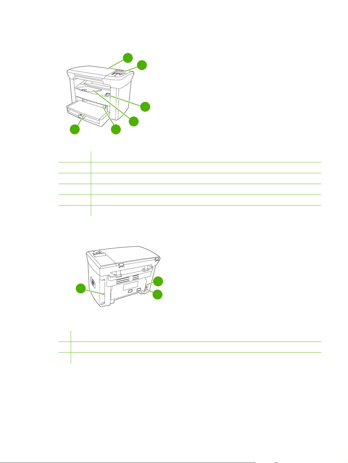
Walkaround
6
Figure 1-2 Front view
1 Flatbed scanner cover
2 Control panel
3 Cartridge-door release
4 Output bin
5 Priority input tray
6 Tray 1
1
2
3
4
5
8
7
9
Figure 1-3 Back view
7 Hi-Speed USB 2.0 port
8 Power switch
9 Power receptacle
ENWW Walkaround 5
Page 22

General guidelines
Some media might meet all of the guidelines in this manual and still not produce satisfactory results.
This problem might be the result of improper handling, unacceptable temperature and humidity levels,
or other variables over which Hewlett-Packard has no control.
Before purchasing large quantities of print media, always test a sample and make sure that the print
media meets the requirements specified in this service manual and in the HP LaserJet Printer Family
Print Media Guide, which you can view on the Web at
CAUTION Using media that does not meet HP specifications can cause problems for the
device, requiring repair. This repair is not covered by the Hewlett-Packard warranty or service
agreements.
The device accepts a variety of media, such as cut-sheet paper (including up to 100% recycled-fibercontent paper), envelopes, labels, transparencies, LaserJet glossy paper, HP LaserJet Tough paper,
and custom-size paper. Properties such as weight, composition, grain, and moisture content are
important factors that affect performance and output quality. Media that does not meet the guidelines
outlined in this manual can cause the following problems:
Poor print quality
●
Increased jams
●
Premature wear on the device, requiring repair
●
www.hp.com/support/ljpaperguide.
Choosing paper and other media
Properties such as weight, grain, and moisture content are important factors that affect performance
and quality. To achieve the best possible print quality, only use high-quality media that is designed for
laser printers.
NOTE Always test a sample of the media before you purchase large quantities. Your media
supplier should understand the requirements specified in the HP LaserJet Printer Family Print
Media Guide (HP part number 5963-7863).
HP media
HP recommends that you use HP LaserJet media in the device.
Media to avoid
The device can handle many types of media. Using media that is outside the specifications degrades
print quality and increases the chance of jams occurring. See
on page 8.
Do not use media that is too rough.
●
Do not use media that contains cutouts or perforations other than standard 3-hole punched paper.
●
Do not use multipart forms.
●
Guidelines for using media
Do not use paper that contains a watermark if you are printing solid patterns.
●
6 Chapter 1 Device information ENWW
Page 23

Media that can damage the device
In rare circumstances media can damage the device. Avoid the following types of media to prevent
possible damage:
Do not use media with staples or paper clips attached.
●
Do not use transparencies designed for inkjet printers or other low-temperature printers. Use only
●
transparencies that are specified for use with HP LaserJet devices.
Do not use photo paper intended for inkjet printers.
●
Do not use paper that is embossed or coated and is not designed for the temperature of the image-
●
fuser. Select media that can tolerate temperatures of 200°C (392°F) for 0.1 second.
HP manufactures a media that is designed for the device.
Do not use letterhead paper that was produced with low-temperature dyes or thermography.
●
Preprinted forms or letterhead must use inks that can tolerate temperatures of 200°C (392°F) for
0.1 second.
Do not use any media that produces emissions, or that melts, offsets, or discolors when exposed
●
to 200°C (392°F) for 0.1 second.
To order HP LaserJet printing supplies, go to
ghp/buyonline.html/ worldwide.
www.hp.com/go/ljsupplies in the U.S. or to www.hp.com/
ENWW Choosing paper and other media 7
Page 24

Guidelines for using media
The following sections provide guidelines and instructions for printing on transparencies, envelopes,
and other special media. Guidelines and specifications are included to help you select media that
optimizes print quality and avoid media that can cause jams or damage the device.
Paper
For best results, use conventional 80-g/m2 or 20-lb paper. Make sure that the paper is of good quality
and free of cuts, nicks, tears, spots, loose particles, dust, wrinkles, voids, and curled or bent edges.
If you are unsure about what type of paper you are loading (such as bond or recycled), check the label
on the package of paper.
Some paper causes print quality problems, jamming, or damage to the device.
Symptom Problem with paper Solution
Poor print quality or toner adhesion
Problems with feeding
Dropouts, jamming, or curl Stored improperly Store paper flat in its moisture-proof
Increased gray background shading Might be too heavy Use lighter paper.
Excessive curl
Problems with feeding
Jamming or damage to device Cutouts or perforations Do not use paper with cutouts or
Problems with feeding Ragged edges Use good quality paper.
Too moist, too rough, too smooth, or
embossed
Too moist, wrong grain direction, or
short-grain construction
Try another kind of paper that has a
smoothness rating of 100-250 Sheffield
and has 4-6% moisture content.
Check the device and make sure that the
appropriate media type has been
selected.
wrapping.
Use long-grain paper.
Check the device and make sure that the
appropriate media type has been
selected.
perforations.
NOTE The device uses heat and pressure to fuse toner to the paper. Make sure that any colored
paper or preprinted forms use inks that are compatible with the fuser temperature of 200°C (392°
F) for 0.1 second.
Do not use letterhead that is printed with low-temperature inks, such as those used in some types
of thermography.
Do not use raised letterhead.
Do not use transparencies that are designed for inkjet printers or other low-temperature printers.
Use only transparencies that are specified for use with HP LaserJet printers.
CAUTION Failure to follow these guidelines could cause jams or damage to the device.
8 Chapter 1 Device information ENWW
Page 25

Colored paper
Colored paper should be of the same high quality as white xerographic paper.
●
Pigments used must be able to withstand the fuser temperature of 200°C (392°F) for 0.1 second
●
without deterioration.
Do not use paper with a colored coating that was added after the paper was produced.
●
Custom-size media
Use the main input tray for multiple sheets.
CAUTION Make sure that the sheets are not stuck together before you load them.
Labels
HP recommends that you print labels from the priority input tray.
CAUTION Do not feed a sheet of labels through the device more than once. The adhesive
degrades and might damage the device.
Label construction
When selecting labels, consider the quality of the following components:
Adhesives: The adhesive material should be stable at 200°C (392°F), the maximum fuser
●
temperature.
Arrangement: Only use labels with no exposed backing between them. Labels can peel off sheets
●
that have spaces between the labels, causing serious jams.
Curl: Before printing, labels must lie flat with no more than 13 mm (0.5 inch) of curl in any direction.
●
Condition: Do not use labels with wrinkles, bubbles, or other indications of separation.
●
Transparencies
Transparencies must be able to withstand 200°C (392°F), the maximum fuser temperature.
CAUTION You can print transparencies from the 150-sheet tray (tray 1). However, do not load
more than 75 transparencies at one time into the tray.
ENWW Guidelines for using media 9
Page 26

Envelopes
HP recommends that you print envelopes from the priority input tray.
Envelope construction
Envelope construction is critical. Envelope fold lines can vary considerably, not only between
manufacturers, but also within a box from the same manufacturer. Successful printing on envelopes
depends upon the quality of the envelopes. When selecting envelopes, consider the following
components:
2
Weight: The weight of the envelope paper should not exceed 90 g/m
●
result.
Construction: Before printing, envelopes should lie flat with less than 6 mm (0.25 inch) of curl,
●
and should not contain air. Envelopes that trap air can cause problems. Do not use envelopes that
contain clasps, snaps, tie strings, transparent windows, holes, perforations, cutouts, synthetic
materials, stamping, or embossing. Do not use envelopes with adhesives that require pressure to
seal them.
Condition: Make sure that the envelopes are not wrinkled, nicked, or otherwise damaged. Make
●
sure that the envelopes do not have any exposed adhesive.
Envelopes with double-side seams
An envelope with double-side-seam construction has vertical seams at both ends of the envelope rather
than diagonal seams. This style might be more likely to wrinkle. Make sure that the seam extends all
the way to the corner of the envelope as shown in the following illustration:
(24 lb), or jamming might
1
2
1 Acceptable envelope construction
2 Unacceptable envelope construction
10 Chapter 1 Device information ENWW
Page 27

Envelopes with adhesive strips or flaps
Envelopes with a peel-off adhesive strip or with more than one flap that folds over to seal must use
adhesives compatible with the heat and pressure in the device: 200°C (392°F). The extra flaps and
strips might cause wrinkling, creasing, or jams.
Envelope storage
Proper storage of envelopes contributes to good print quality. You should store envelopes flat. If air is
trapped in an envelope, creating an air bubble, the envelope might wrinkle during printing.
Card stock and heavy media
You can print many types of card stock from the input tray, including index cards and postcards. Some
card stock performs better than others because its construction is better suited for feeding through a
laser printer.
2
For optimum performance, do not use paper heavier than 157 g/m
cause misfeeds, stacking problems, jams, poor toner fusing, poor print quality, or excessive mechanical
wear.
NOTE You might be able to print on heavier paper if you do not fill the input tray to capacity
and if you use paper with a smoothness rating of 100-180 Sheffield.
(42 lb). Paper that is too heavy might
In either the software program or the printer driver, select Heavy (106 g/m2 to 163 g/m2; 28- to 43-lb
bond) or Cardstock (135 g/m
2
to 216 g/m2; 50- to 80-lb cover) as the media type, or print from a tray
that is configured for heavy paper. Because this setting affects all print jobs, it is important to return the
device back to its original settings after the job has printed.
Card stock construction
Smoothness: 135-157 g/m
●
100-180 Sheffield. 60-135 g/m
100-250 Sheffield.
Construction: Card stock should lie flat with less than 5 mm (0.2 inch) of curl.
●
Condition: Make sure that the card stock is not wrinkled, nicked, or otherwise damaged.
●
2
(36-42 lb) card stock should have a smoothness rating of
2
(16-36 lb) card stock should have a smoothness rating of
Card stock guidelines
Set margins at least 2 mm (0.08 inch) away from the edges.
●
Use tray 1 for card stock (135 g/m2 to 216 g/m2; 50- to 80-lb cover).
●
ENWW Guidelines for using media 11
Page 28

Letterhead and preprinted forms
Letterhead is premium paper that often has a watermark, sometimes uses cotton fiber, and is available
in a wide range of colors and finishes with matching envelopes. Preprinted forms can be made of a
broad spectrum of paper types ranging from recycled to premium.
Many manufacturers now design these grades of paper with properties optimized for laser printing and
advertise the paper as laser compatible or laser guaranteed. Some of the rougher surface finishes, such
as cockle, laid, or linen, might require the special fuser modes that are available on some device models
to achieve adequate toner adhesion.
NOTE Some page-to-page variation is normal when printing with laser printers. This variation
cannot be observed when printing on plain paper. However, this variation is obvious when printing
on preprinted forms because the lines and boxes are already placed on the page.
To avoid problems when using preprinted forms, embossed paper, and letterhead, observe the following
guidelines:
Avoid using low-temperature inks (the kind used with some types of thermography).
●
Use preprinted forms and letterhead paper that have been printed by offset lithography or
●
engraving.
Use forms that have been created with heat-resistant inks that will not melt, vaporize, or release
●
emissions when heated to 200°C (392°F) for 0.1 second. Typically, oxidation-set or oil-based inks
meet this requirement.
When the form is preprinted, be careful not to change the moisture content of the paper, and do
●
not use materials that change the paper's electrical or handling properties. Seal the forms in
moisture-proof wrap to prevent moisture changes during storage.
Avoid processing preprinted forms that have a finish or coating.
●
Avoid using heavily embossed or raised-letterhead papers.
●
Avoid papers that have heavily textured surfaces.
●
Avoid using offset powders or other materials that prevent printed forms from sticking together.
●
NOTE To print a single-page cover letter on letterhead, followed by a multiple-page document,
feed the letterhead face up in the priority input tray, and load the standard paper in the main input
tray (tray 1). The device automatically prints from the priority input tray first.
12 Chapter 1 Device information ENWW
Page 29

Supported media weights and sizes
For optimum results, use conventional 80 to 90 g/m2 (20 to 24 lb) photocopy paper. Verify that the paper
is of good quality and is free of cuts, nicks, tears, spots, loose particles, dust, wrinkles, curls, and bent
edges.
NOTE The device supports a wide range of standard and custom sizes of print media. The
capacity of trays and bins can vary depending on media weight and thickness and on
environmental conditions. Use only transparencies that are designed for use with HP LaserJet
printers. Inkjet and monochrome transparencies are not supported for the device.
Table 1-3 Priority input tray specifications
Media Dimensions
1
Paper Minimum: 89 x 44 mm (3.5 x
1.75 inches)
Weight Capacity
42 to 260 g/m2 (11 to 69 lb) Up to 10 sheets of 80 g/m2 or 20 lb
paper
2
Maximum: 216 x 356 mm (8.5 x
14 inches)
HP Cover paper
3
Same as the preceding listed
203 g/m2 (75 lb cover)
1 sheet
minimum and maximum sizes
Transparencies and opaque
film
4
Labels
Thickness: 0.10 to 0.13 mm (3.9
to 5.1 mils)
Thickness: up to 0.23 mm (up to
1 transparency
1 sheet of labels
9 mils)
Envelopes
1
The device supports a wide range of standard and custom sizes of print media. Check the printer driver for supported sizes.
2
Capacity can vary depending on media weight and thickness, and environmental conditions.
3
Hewlett-Packard does not guarantee results when printing with other types of heavy paper.
4
Smoothness: 100 to 250 (Sheffield).
Up to 90 g/m2 (16 to 24 lb)
Up to 10
Table 1-4 Tray 1 specifications
Media Dimensions
Minimum size 76 x 127 mm (3 x 5 inches)
Maximum size 216 x 356 mm (8.5 x 14 inches)
1
Weight Capacity
60 to 163 g/m2 (16 to 43 lb) 150 sheets of 80 g/m2 (20 lb)
paper
2
Letter 216 x 279 mm (8.5 x 11 inches)
A4 210 x 297 mm (8.3 x 11.7 inches)
Legal 216 x 356 mm (8.5 x 14 inches)
A5 148 x 210 mm (5.8 x 8.3 inches)
B5 (ISO) 176 x 250 mm (6.9 x 9.9 inches)
B5 (JIS) 182 x 257 mm (7.2 x 10 inches)
Executive 191 x 267 mm (7.3 x 10.5 inches)
8.5 x 13 inches 216 x 330 mm (8.5 x 13 inches)
1
The device supports a wide range of standard sizes of print media. Check the printer driver for supported sizes.
2
Capacity can vary depending on the media weight and thickness, and environmental conditions.
ENWW Supported media weights and sizes 13
Page 30

Printing and storage environment
Ideally, the printing and media-storage environment should be at or near room temperature, and not too
dry or too humid. Remember that paper absorbs and loses moisture rapidly.
Heat works with humidity to damage paper. Heat causes the moisture in paper to evaporate, while cold
causes it to condense on the sheets. Heating systems and air conditioners remove most of the humidity
from a room. As paper is opened and used, it loses moisture, causing streaks and smudging. Humid
weather or water coolers can cause the humidity to increase in a room. As paper is opened and used
it absorbs any excess moisture, causing light print and dropouts. Also, as paper loses and gains moisture
it can distort. This issue can cause jams.
As a result, paper storage and handling are as important as the paper-making process itself. Paper
storage environmental conditions directly affect the feed operation and print quality.
Care should be taken not to purchase more paper than can be easily used in a short time (about three
months). Paper stored for long periods can experience heat and moisture extremes, which can cause
damage. Planning is important to prevent damage to a large supply of paper.
Unopened paper in sealed reams can remain stable for several months before use. Opened packages
of paper have more potential for environmental damage, especially if they are not wrapped with a
moisture-proof barrier.
The media-storage environment should be maintained to ensure optimum performance. The required
condition is 20° to 24°C (68° to 75°F), with a relative humidity of 45% to 55%. The following guidelines
are helpful when evaluating the storage environment:
Print media should be stored at or near room temperature.
●
The air should not be too dry or too humid.
●
The best way to store an opened ream of paper is to rewrap it tightly in its moisture-proof wrapping.
●
If the device environment is subject to extremes, unwrap only the amount of paper to be used
during the day's operation to prevent unwanted moisture changes.
Avoid storing paper and print media near heating and air conditioning vents or near windows and
●
doors that are frequently open.
14 Chapter 1 Device information ENWW
Page 31

2 Installation
What is in the box
●
Site requirements
●
Loading media
●
Connect power
●
Minimum system requirements
●
Supported operating systems
●
Software installation
●
Printer driver
●
Software for Windows
●
ENWW 15
Page 32
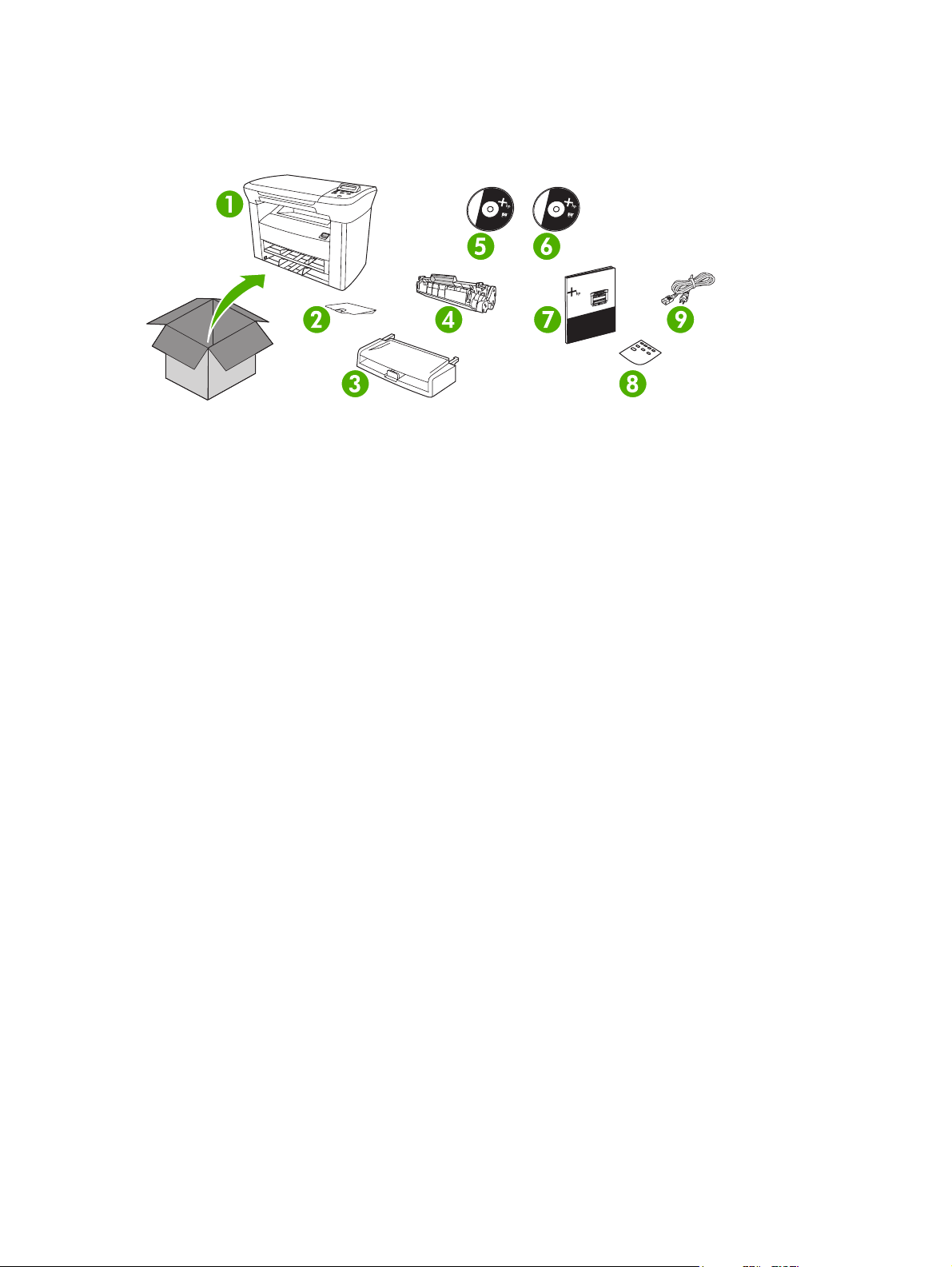
What is in the box
The following items come in the box with the device.
Figure 2-1 What is in the shipping box
1. HP LaserJet M1005 MFP
2. Output bin support
3. Main input tray (tray 1)
4. Print cartridge
5. Software and documentation CD-ROM
6. Readiris CD-ROM
7. Getting started guide
8. Control panel overlay
9. Power cord
16 Chapter 2 Installation ENWW
Page 33

Site requirements
Select a sturdy, well-ventilated, dust-free area that is away from direct sunlight to position the device.
Allow enough space around the device to open the doors and trays.
Physical specifications
NOTE Device weight does not include the print cartridge, which weighs 0.7 kg (1.5 lb).
Table 2-1 Physical dimensions for the HP LaserJet M1005 MFP
Device model Height Depth Width Weight
HP LaserJet M1005 MFP 308 mm (12.1 in) 363 mm (14.3 in) 437 mm (19.3 in) 8.3 kg (18.4 lb)
Space requirements
The device must have the following amount of space above and around it for proper access and
ventilation.
Width: 500 mm (19.7 in)
●
Depth: 480 mm (19 in)
●
Height: 560 mm (22 in)
●
Figure 2-2 Space requirements
ENWW Site requirements 17
Page 34

Loading media
The following sections describe how to load media into the different input trays.
CAUTION Printing on wrinkled, folded, or damaged media can cause jams.
Loading documents to copy or scan
Use these instructions to load originals into the device for scanning.
1. Lift the flatbed scanner cover.
2. Place the original document face-down on the flatbed scanner with the upper-left corner of the
document at the lower-right corner of the glass.
Figure 2-3 Loading documents to copy or scan
3. Gently close the lid.
The document is ready to be copied or scanned.
Loading input trays
Main input tray (tray 1)
Figure 2-4 Loading the main input tray (tray 1) (1 of 2)
2
The main input tray holds up to 150 pages of 80 g/m
(15 mm (0.6 in) or less stack height). Load media with the top forward and the side to be printed facing
down. To prevent jams and skewing, always adjust the side and rear media guides.
or 20 lb paper or fewer pages of heavier media
18 Chapter 2 Installation ENWW
Page 35

Figure 2-5 Loading the main input tray (tray 1) (2 of 2)
NOTE When you add new media, make sure that you remove all of the media from the input
tray and straighten the stack of new media. This helps to prevent multiple sheets of media from
feeding into the device, which can cause jams.
Priority input tray
Figure 2-6 Loading the priority input tray (1 of 2)
The priority input tray on the HP LaserJet M1005 MFP holds up to 10 sheets of media up to 80 g/m
2
(20 lb) in weight or one envelope, transparency, or card. Load media with the top forward and the side
to be printed facing up. To prevent jams and skewing, always adjust the side media guides before
feeding the media.
Figure 2-7 Loading the priority input tray (2 of 2)
ENWW Loading media 19
Page 36

Connect power
Make sure that the power cord is connected to the device and to a power supply.
Figure 2-8 Connect power
20 Chapter 2 Installation ENWW
Page 37

Minimum system requirements
In order to install and use the device software, your computer must meet the following minimum
requirements:
Windows requirements
Pentium II (233 MHz) processor
●
64 MB of RAM
●
35 MB of disk space
●
SVGA 800x600 16-bit color monitor
●
Macintosh requirements
G3, G4, or G5 PowerPC processor
●
128 MB of RAM
●
30 to 50 MB of disk space
●
Supported operating systems
The device comes with software for the following operating systems:
Windows XP
●
Windows 2000
●
Windows Server 2003
●
Mac OS X V10.3 and later (print/twain drivers only)
●
ENWW Minimum system requirements 21
Page 38

Software installation
If the computer meets the recommended minimum requirements, the installation process includes the
following software.
Windows
HP LaserJet Scan software program and driver (twain)
●
Readiris OCR (not installed with other software; separate installation is required)
●
Printer drivers (Windows and Mac)
●
Macintosh
Readiris OCR (not installed with other software; separate installation is required)
●
Printer drivers (Windows and Mac)
●
TWAIN driver (Mac)
●
22 Chapter 2 Installation ENWW
Page 39

Printer driver
The device comes with software for Windows and Macintosh that allows the computer to communicate
with the device. This software is called a printer driver. Printer drivers provide access to device features,
such as printing on custom-sized paper, resizing documents, and inserting watermarks.
NOTE The most recent drivers are available at www.hp.com. Depending on the configuration
of Windows-based computers, the installation program for the device software automatically
checks the computer for Internet access in order to obtain the latest drivers.
Printer-driver Help
Printer-driver Help is separate from program Help. The printer-driver Help provides explanations for the
buttons, check boxes, and drop-down lists that are in the printer driver. It also includes instructions for
performing common printing tasks, such as printing on both sides, printing multiple pages on one sheet,
and printing the first page or covers on different paper.
Activate the printer-driver Help screens in one of the following ways:
Windows Macintosh
In the printer driver Properties dialog box, click the
●
Help button.
Press the F1 key on the computer keyboard.
●
Click the question-mark symbol in the upper-right corner
●
of the printer driver.
Right-click on any item in the driver, and then click What's
●
This?.
In the Print dialog box, click the ? button.
ENWW Printer driver 23
Page 40

Changing printer-driver settings
Use one of the following methods to open the printer drivers from the computer in order to change
settings:
Operating System To change the settings for all
print jobs until the software
program is closed
Windows 2000, XP,
and Server 2003
Mac OS X V10.3 and
Mac OS X V10.4
1. On the File menu in the
software program, click
Print.
2. Select the name of the
device, and then click
Properties or
Preferences.
The steps can vary; this
procedure is most common.
1. On the File menu, click
Print.
2. Change the settings that
you want on the various
pop-up menus.
To change the print job default
settings (for example, select a
specific media type or size by
default)
1. Click Start, click Settings,
and then click Printers or
Printers and Faxes.
2. Right-click the printer icon,
and then select Printing
Preferences.
1. On the File menu, click
Print.
2. Change the settings that
you want on the various
pop-up menus.
3. On the Presets pop-up
menu, click Save as and
type a name for the preset.
These settings are saved in the
Presets menu. To use the new
settings, you must select the
saved preset option every time
you open a program and print.
To change the configuration
settings (for example, enable
or disable manual duplexing)
1. Click Start, click Settings,
and then click Printers or
Printers and Faxes.
2. Right-click the printer icon,
and then select
Properties.
3. Click the Device Settings
tab.
1. Open Printer Setup Utility
by selecting the hard drive,
clicking Applications,
clicking Utilities, then
double-clicking Printer
Setup Utility.
2. Click on the print queue.
3. On the Printers menu,
click Show Info.
4. Click the Installable
Options menu.
24 Chapter 2 Installation ENWW
Page 41

Software for Windows
See the HP LaserJet M1005 MFP getting started guide for installation instructions, and see the Readme
file for the latest software information.
HP LaserJet Scan software
The software CD includes the HP LaserJet Scan software. See the Readme file that is provided on the
CD for additional included software and for supported languages.
Installing Windows device software
Insert the software CD that came with the device into the computer CD-ROM drive. Follow the onscreen installation instructions.
NOTE If the Welcome screen does not open, click Start on the Windows task bar, click Run,
type Z:\setup (where Z is your CD drive letter), and click OK.
Uninstalling Windows device software
1. Click Start, and then click All Programs.
2. Click HP, and then click HP LaserJet M1005 MFP.
3. Click Uninstall HP LaserJet M1005 MFP, and then follow the onscreen instructions to remove the
software.
Uninstalling Macintosh device software
1. Double-click the hard drive icon on the desktop.
2. Open the Applications folder, and then open the Utilities folder.
3. Double-click Printer Setup Utility.
4. In the Printer Setup Utility, select the device, and then click Delete on the toolbar.
ENWW Software for Windows 25
Page 42

26 Chapter 2 Installation ENWW
Page 43

3 Managing the device
Control panel
●
Information pages
●
Managing supplies
●
Supplies
●
Cable and interface accessories
●
User-replaceable parts
●
Paper and other print media
●
ENWW 27
Page 44

Control panel
1
Figure 3-1 Control panel
1 Control-panel display
2 Left arrow button
3 Menu/Enter/OK button
2
3
9
4
5
6
7
8
Shows status information, menus, and error messages
●
Navigates to the previous item in the list, or decreases the value of numeric
●
items. With some numeric items, pressing the button once decreases the value
by 1, while pressing and holding the button decreases the value by 10.
Activates the control-panel menus
●
Clears an error condition when the condition is clearable
●
Saves the selected value for an item
●
4 Right arrow button
5 Cancel button
6 More Copy Settings button
7 Lighter/Darker button
8 # Copies button
9 Start Copy button
Performs the action that is associated with the item that is highlighted on the
●
control-panel display
Navigates to the next item in the list, or increases the value of numeric items.
●
With some numeric items, pressing the button once increases the value by 1,
while pressing and holding the button increases the value by 10.
Cancels the current print, copy, or scan job in process and expels all of the
●
active pages from the paper path. The time that it takes to cancel the job
depends on the size of the print job. (Press the button only once.) Also clears
continuable errors that are associated with the canceled job.
Exits the control-panel menus
●
Provides access to copy settings for the current copy job
●
Provides access to copy contrast settings for the current copy job
●
Provides a way to change the number of copies printed for a the current copy
●
job
Starts a copy job
●
28 Chapter 3 Managing the device ENWW
Page 45

Information pages
Information pages reside within the device memory. These pages help to diagnose and solve problems
with the device.
Page name Description Instructions
Demo page The Demo page prints a sample page that
Menu structure The Menu structure is a “map” of the control-
Configuration
report
allows you to inspect the device print quality.
panel menu commands.
The Configuration report lists the current
settings and properties of the device.
1. Product Information. This section
contains basic information about the
device, such as the device name, the
serial number, and memory information.
2. Product Settings. This section lists
Language, Jam Recovery, and I/O
Timeout.
3. Paper Settings. This section lists
information about the media type for each
tray and about the type settings for all of
the media that the device supports.
1. On the device control panel, press Menu.
2. Use the < or the > button to select Reports, and
then press Menu.
3. Press Menu to select Demo page.
1. On the device control panel, press Menu.
2. Use the < or the > button to select Reports, and
then press Menu.
3. Use the < or the > button to select Menu
structure, and then press Menu.
1. On the device control panel, press Menu.
2. Use the < or the > button to select Reports, and
then press Menu.
3. Use the < or the > button to select Config
report, and then press Menu.
4. Copy Settings. This section lists the
device default copy settings.
5. Usage. This section shows the number of
print, copy, and scan jobs performed by
the device.
6. Status Log. This section contains
information about device errors.
ENWW Information pages 29
Page 46

Managing supplies
Checking supplies status
If the supply levels are low, you can order supplies through your local HP dealer, by telephone, or online.
See chapter 7 for part numbers. See
Storing supplies
Follow these guidelines for storing print cartridges:
Do not remove the print cartridge from its package until you are ready to use it.
●
CAUTION To prevent damage, do not expose the print cartridge to light for more than a
few minutes.
Store the supply in a horizontal position.
●
Store the supply in a dark, dry location away from heat and magnetic sources.
●
Replacing and recycling supplies
To install a new HP print cartridge, see Changing the print cartridge on page 40.
To recycle supplies, place the used supply in the box in which the new supply arrived. Use the enclosed
return label to send the used supply to HP for recycling. For complete information, see the recycling
guide that is included with each new HP supply item.
www.hp.com/go/ljsupplies to order online.
HP policy on non-HP supplies
Hewlett-Packard Company cannot recommend the use of non-HP supplies, either new or
remanufactured. Because they are not HP products, HP cannot influence their design or control their
quality. Service or repairs required as a result of using a non-HP supply are not covered under the
warranty.
30 Chapter 3 Managing the device ENWW
Page 47

HP fraud hotline
Call the HP fraud hotline if the device indicates that the print cartridge is not an HP print cartridge and
you think that it is genuine. HP will help determine if the device is genuine and take steps to resolve the
problem.
Your print cartridge might not be genuine HP if you notice the following issues:
You are experiencing a large number of problems with the print cartridge.
●
The print cartridge does not look like it usually does (for example, the pull tab or the box is different).
●
In the United States, call toll-free: 1-877-219-3183.
Outside the United States, you can call collect. Dial the operator and ask to place a collect call to this
telephone number: 1-770-263-4745. If you do not speak English, a representative at the HP fraud hotline
who speaks your language will assist you. Or, if someone who speaks your language is not available,
a language line interpreter will connect approximately one minute after the beginning of the call. The
language line interpreter is a service that translates between you and the representative for the HP fraud
hotline.
ENWW Managing supplies 31
Page 48

Supplies
Product name Description Part number
Black print cartridge The average yield for the standard print
cartridge is approximately 2,000 pages in
accordance with ISO/IEC 19752. Actual
yield depends on specific use.
Cable and interface accessories
Product name Description Part number
USB cable 2-meter standard USB-compatible
device connector
User-replaceable parts
Product name Description Part number
Separation pad and pickup rollers Replace when the device is picking up
multiple sheets or no sheets. Trying
different paper did not resolve the
problem.
Q2612A
C6518A
Contact HP Customer Care to order
parts.
Paper and other print media
NOTE Inkjet paper is not recommended for the device.
Product name Description Part number
HP LaserJet paper Premium HP-brand paper for use with
HP LaserJet printers.
HP Premium Choice LaserJet
paper
HP Printing paper HP-brand paper for use with HP LaserJet
HP Multipurpose paper HP-brand paper for a variety of uses. HPM1120 (letter)
HP LaserJet Tough paper Robust paper with a satin finish. Paper does not
HP High Gloss laser paper High-gloss finish coating on both sides. Use for
HP Soft Gloss laser paper
HP bond paper with a weight of 120 g/m2 (32 lb).
printers.
tear and withstands the weather. For
documents requiring durability and longevity.
brochures, catalogs, photographs, and
whenever a high-gloss finish is desired.
Satin finish coating on both sides, 105 g/m
(28 lb).
HPJ1124 (letter)
HPU1132 (letter)
HPP1122 (letter)
Q1298A (letter)
Q2419A (letter) 200 sheets
2
Q2415A (letter) 500 sheets
32 Chapter 3 Managing the device ENWW
Page 49

Product name Description Part number
HP Brochure Laser Paper, Matte High opacity for two-sided printing with no
show-through, 44 lb.
HP Photo and Imaging Laser
High-contrast glossy finish, 32 lb. Q6545A (letter) 200 sheets
Paper, Glossy
HP Photo and Imaging Laser
High-contrast matte finish, 52 lb. Q6549A (letter) 100 sheets
Paper, Matte
HP Presentation Laser Paper,
Bright white for high contrast, 32 lb. Q6541A (letter) 200 sheets
Soft Gloss
HP Recycled Content Paper Matte finish on both sides, contains 30 percent
post-consumer content (satisfies US Executive
Order 13101), 75 g/m
2
(20-lb bond).
Q6543A (letter) 150 sheets
HPE1120 (letter) 500 sheets
ENWW Paper and other print media 33
Page 50

34 Chapter 3 Managing the device ENWW
Page 51

4 Maintenance
Cleaning the device
●
Print cartridge
●
Replacing supplies and parts
●
ENWW 35
Page 52

Cleaning the device
To clean the exterior
Use a soft, damp, lint-free cloth to wipe dust, smudges, and stains off of the exterior of the device.
To clean the scanner glass
Dirty glass, from fingerprints, smudges, hair, and so on, affects the accuracy of special features such
as fit-to-page and copy.
1. Turn off the device, unplug the power cord from the electrical socket, and raise the lid.
2. Clean the glass by using a soft cloth or sponge that has been moistened with nonabrasive glass
cleaner.
Figure 4-1 Cleaning the scanner glass
CAUTION Do not use abrasives, acetone, benzene, ammonia, ethyl alcohol, or carbon
tetrachloride on any part of the device; these can damage the device. Do not place liquids
directly on the glass. They might seep under it and damage the device.
3. To prevent spotting, dry the glass by using a chamois or cellulose sponge.
To clean the lid backing
Minor debris can accumulate on the white document lid backing that is located underneath the scanner
lid.
1. Turn off the device, unplug the power cord from the electrical socket, and raise the lid.
36 Chapter 4 Maintenance ENWW
Page 53

2. Clean the white document lid backing by using a soft cloth or sponge that has been moistened with
a mild soap and warm water.
Figure 4-2 Cleaning the lid backing
3. Wash the backing gently to loosen debris; do not scrub the backing.
4. Dry the backing by using a chamois or soft cloth.
CAUTION Do not use paper-based wipes because they might scratch the backing.
5. If this does not clean the backing well enough, repeat the previous steps and use isopropyl alcohol
to dampen the cloth or sponge, and then wipe the backing thoroughly with a damp cloth to remove
any residual alcohol.
To clean the paper path
The device features a special cleaning mode to clean the paper path.
1. On the device control panel, press Menu.
2. Use the < or the > button to select Service, and then press Menu.
3. Use the < or the > button to select Cleaning Mode, and then press Menu.
A page feeds through the device slowly. Discard the page when the process is completed.
4. Load plain letter or A4 paper when you are prompted.
5. Press Menu again to confirm and begin the cleaning process.
A page feeds through the device slowly. Discard the page when the process is completed.
ENWW Cleaning the device 37
Page 54

Print cartridge
Using, storing, and monitoring the print cartridge can help ensure high-quality device output.
Approximate print-cartridge replacement intervals
Print cartridge Page count
Black 2,000 pages
To order supplies online, go to www.hp.com/support/LJm_1005.
Managing the print cartridge
Print-cartridge life expectancy
The average cartridge yield is 2,000 pages in accordance with ISO/IEC 19752. Actual cartridge yield
depends on specific use.
CAUTION Hewlett-Packard does not recommend full-time use of EconoMode. (If EconoMode
is used consistently to print media with less than 5% toner coverage, the toner supply might
outlast the mechanical parts in the print cartridge.)
Print-cartridge storage
Do not remove the print cartridge from its package until you are ready to use it.
CAUTION To prevent damage to the print cartridge, do not expose it to light for more than a
few minutes.
HP policy on non-HP print cartridges
Hewlett-Packard Company cannot recommend the use of non-HP print cartridges, either new or
remanufactured. Because they are not HP products, HP cannot influence their design or control their
quality.
NOTE Any damage caused by a non-HP print cartridge is not covered under the HP warranty
and service agreements.
To install a new HP print cartridge, see Changing the print cartridge on page 40. To recycle the used
cartridge, follow the instructions included with the new cartridge.
HP fraud hotline
Call the HP fraud hotline if the device indicates that the print cartridge is not an HP print cartridge and
you think that it is genuine. HP will help determine if the product is genuine and take steps to resolve
the problem.
38 Chapter 4 Maintenance ENWW
Page 55

Your print cartridge might not be genuine HP if you notice the following issues:
You are experiencing a large number of problems with the print cartridge.
●
The print cartridge does not look like it usually does (for example, the pull tab or the box is different).
●
In the United States, call toll-free: 1-877-219-3183.
Outside the United States, you can call collect. Dial the operator and ask to place a collect call to this
telephone number: 1-770-263-4745. If you do not speak English, a representative at the HP fraud hotline
who speaks your language will assist you. Or, if someone who speaks your language is not available,
a language line interpreter will connect approximately one minute after the beginning of the call. The
language line interpreter is a service that translates between you and the representative for the HP fraud
hotline.
ENWW Print cartridge 39
Page 56

Replacing supplies and parts
Carefully follow the guidelines in this section when replacing device supplies.
Supply replacement guidelines
To facilitate the replacement of supplies, keep the following guidelines in mind when setting up the
device.
Sufficient space is required above and in the front of the device for removing supplies.
●
The device should be located on a flat, sturdy surface.
●
For instructions on installing supplies, see the installation guides provided with each supply item or see
more information at
CAUTION Hewlett-Packard recommends the use of HP products in this device. Use of non-
HP products might cause problems requiring service that is not covered by the HP warranty or
service agreements.
Changing the print cartridge
1. Open the print-cartridge door.
www.hp.com/support/LJm_1005.
Figure 4-3 Changing the print cartridge (1 of 5)
2. Grasp the handle on the print cartridge and then pull the cartridge straight out to remove it. See
the recycling information inside the print cartridge box.
Figure 4-4 Changing the print cartridge (2 of 5)
40 Chapter 4 Maintenance ENWW
Page 57
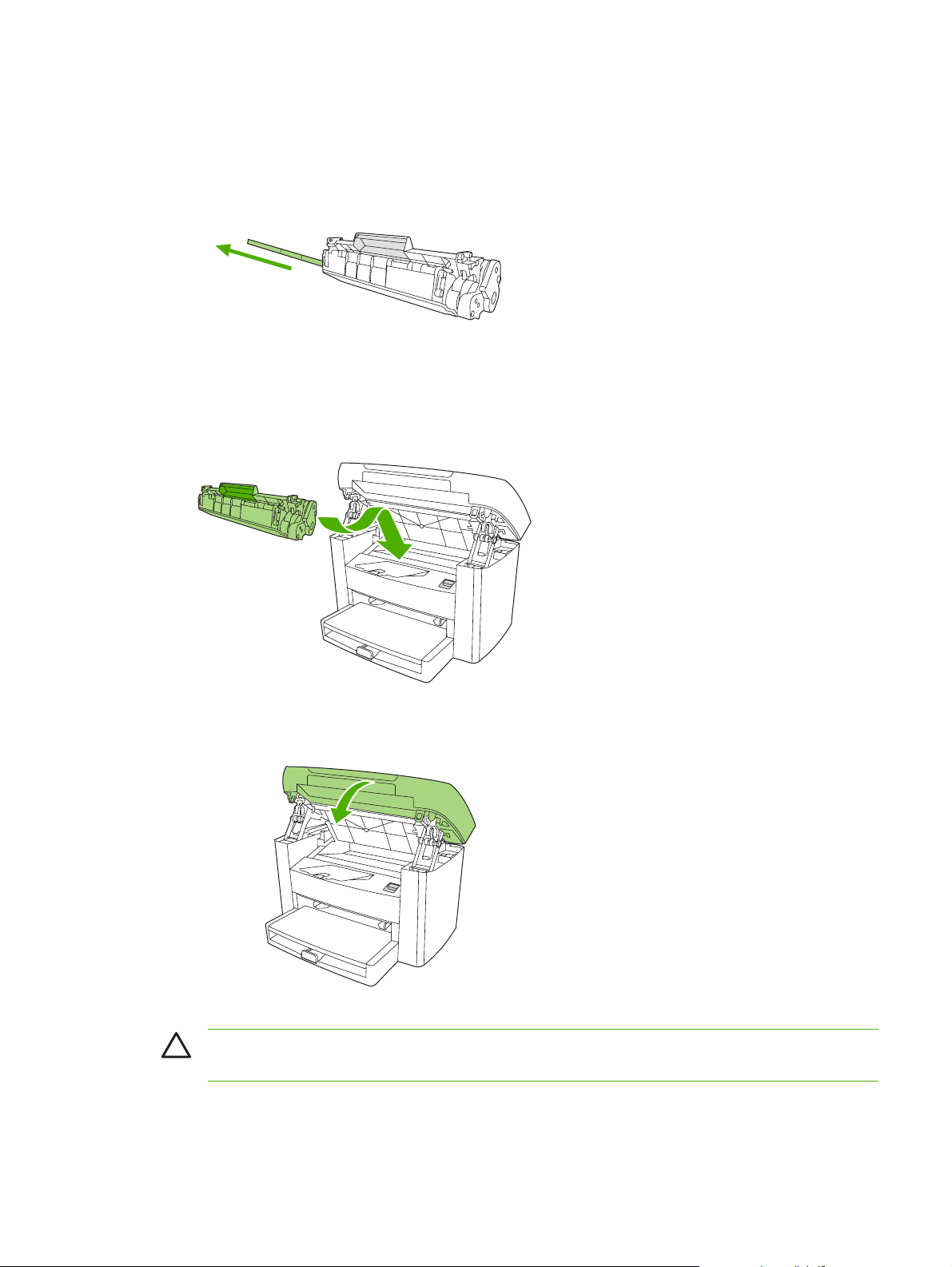
3. Remove the new print cartridge from its packaging, remove the cover from the print cartridge, and
then remove the sealing tape.
Figure 4-5 Changing the print cartridge (3 of 5)
4. Insert the cartridge into the device until it is firmly in place.
Figure 4-6 Changing the print cartridge (4 of 5)
5. Close the print-cartridge door.
Figure 4-7 Changing the print cartridge (5 of 5)
CAUTION If toner gets on your clothing, wipe it off with a dry cloth and wash the clothing in cold
water. Hot water sets toner into the fabric.
ENWW Replacing supplies and parts 41
Page 58

42 Chapter 4 Maintenance ENWW
Page 59

5 Theory of Operation
Basic functions
●
Basic sequence of operation
●
Formatter system
●
Device functions
●
HP LaserJet M1005 MFP unique components
●
ENWW 43
Page 60

Basic functions
This chapter presents a functional overview of the HP LaserJet M1005 MFP. The following systems are
discussed:
device functions and operation
●
engine controller unit (ECU) system/power system
●
laser/scanner system
●
image-formation system
●
paper-feed system (device) and document-feed system (document scanner)
●
formatter functions
●
scanner functions and operation
●
The full device consists of the following components:
the scanner (the HP LaserJet M1005 MFP uses a flatbed contact image scanner (CIS))
●
the printer
●
the formatter
●
The ECU controls the operation sequences of the device.
Figure 5-1 Device configuration
44 Chapter 5 Theory of Operation ENWW
Page 61

Basic sequence of operation
The microprocessor (CPU) on the ECU controls the operation sequence of the device. The following
events take place during normal device operation:
Table 5-1 HP LaserJet M1005 MFP
Period Purpose Remarks
WAIT. After the device is turned on
until Ready appears on the control-panel
display.
READY. From the end of the WAIT
period until the user initiates action.
CALIBRATION. From the time the copy
or scan button is pressed until the SCAN
period.
SCAN. From the end of the
CALIBRATION period until the scan bar
returns to the home position.
To perform the firmware initialization. Tests RAM and establishes
To keep the device ready to print, copy,
or scan.
To compensate for variables in the
scanning system.
To scan one page of the original
document.
communication with the control panel.
This occurs before the scan bar moves
past the media.
ENWW Basic sequence of operation 45
Page 62

Formatter system
The formatter coordinates the major systems. It is responsible for the following tasks or actions:
formatting and controlling copies
●
receiving and processing print data from the device interface
●
monitoring the control panel and relaying device-status information
●
developing and coordinating data placement and timing with the print engine
●
communicating with the host computer through the bidirectional interface
●
The formatter receives print data from the universal serial bus (USB) interface in a compressed raster
format. The firmware decompresses the raster data and sends the data to the ECU. The ECU initiates
the printing processes to transfer the data to the page.
Central processing unit
The formatter incorporates an embedded Tensilica processor operating at 230 MHz.
Standard boot process
When the device is unplugged or the power is off, the firmware code is stored on the formatter in two
blocks. The first block of code is an executable boot block (about 64K of code). The second block of
code is a compressed version of the device control code.
When the device is turned on, the boot block decompresses the device control code and stores it in
RAM. Then the device performs a full startup with the control code running from RAM.
Device startup messages
The LCD display contains different messages depending upon the progress of the boot process:
Table 5-2 Device startup messages
Message Cause Solution
-blank- (Blank display for many seconds after
power-on.) Boot-block failure.
Contact Service Control-code failure. Replace the formatter. See Formatter
Hewlett Packard The device is starting up. Wait for the Ready message.
Ready......... Device startup is complete and the
device is ready for use.
Use the power switch to turn the power
to the device off. Check all wire-harness
connectors and FFCs to make sure that
they are firmly connected.
Replace the formatter. See
on page 94.
on page 94.
Begin using the device.
Formatter
46 Chapter 5 Theory of Operation ENWW
Page 63

RAM
The device contains two types of random-access memory (RAM):
One bank of nonvolatile RAM (NVRAM) stores parameters.
●
Dynamic random access memory (DRAM) provides temporary storage of the device program code
●
along with copy, scan, and print data.
Universal serial bus (USB) interface
The formatter receives incoming data through its USB interface. This interface provides high-speed,
two-way communication between the device and the host, allowing you to change device settings and
monitor device status from the host computer.
Control panel
The control panel consists of the following features:
groups of buttons to control copy and menu navigation
●
a 2-by-16 LCD display that shows status, menus, and messages
●
EconoMode
Select EconoMode to do the following:
enable the device to use less toner
●
extend the life of the toner supply
●
possibly reduce cost-per-page
●
NOTE Using EconoMode reduces print quality because the printed image is lighter.
HP does not recommend full-time use of EconoMode. If EconoMode is used full-time, the toner supply
can outlast the mechanical parts in the print cartridge. If print quality degrades under these
circumstances, you must install a new toner cartridge, even if toner remains in the existing cartridge.
ENWW Formatter system 47
Page 64

Device functions
Device functions are divided into five groups:
engine control
●
formatter
●
image formation
●
laser/scanner
●
pickup and feed
●
The following figure is a block diagram of the device:
Output tray
To external device
(host computer, etc.)
LASER/SCANNER UNIT
Scanning mirror
Laser
diode
Scanner
motor
IMAGEFORMATION
SYSTEM
Cleaning
Fuser
unit
Figure 5-2 Device functional block diagram
unit
BD
sensor
Primary
charging
roller
Photo
sensitive
drum
Transfer
charging
roller
Develop-
ing unit
FORMATTER
ENGINE CONTROL SYSTEM
Engine power assembly
ECU
Priority input tray
Pickup
control
unit
Main input tray
PAPER PICKUP/FEED
SYSTEM
Engine control system (engine control unit and power-supply assembly)
The engine control system coordinates all print engine activities. The engine control system includes
both the engine control unit (ECU) printed circuit assembly (PCA) and the power-supply assembly PCA.
48 Chapter 5 Theory of Operation ENWW
Page 65

NOTE In other HP LaserJet devices, the ECU and power functions are combined onto one PCA
known as the controller PCA or the DC controller PCA. In the HP LaserJet M1005 MFP, the
control functions are primarily relegated to the ECU PCA and the power functions to the powersupply assembly PCA.
The ECU controls the following systems and functions:
Device engine control
●
paper-motion monitoring and control (printing)
●
motor
●
Device laser/scanner unit
●
The power-supply assembly provides the following functions to the power system:
ac power distribution
●
dc power distribution
●
overcurrent/overvoltage protection
●
high-voltage power distribution
●
Device engine control system
Paper motion monitoring and control. The ECU controls paper motion in the device by continuously
monitoring the two paper sensors and coordinating the timing with the other print processes.
Motor. The ECU controls the motor. The motor drives all of the device paper movement.
Device laser/scanner unit
The ECU sends signals to the laser/scanner assembly to modulate the laser-diode on and off modes
and to drive the laser/scanner motor.
Power system on the power-supply assembly
The ac, dc, and high-voltage power supply circuits are all provided by the power-supply assembly.
Ac power distribution
The ac power circuitry supplies ac voltage whenever the power cord is connected to the ac power source
and the power switch is on. The ac voltage is distributed to the dc power supply circuitry and to the ac
driver circuitry, which controls ac voltage to the fuser assembly heating element.
Dc power distribution
The dc power distribution circuitry, located on the engine power assembly, distributes +3.3 Vdc, +5 Vdc,
and +24 Vdc as follows:
Table 5-3 Dc power distribution
+3.3 Vdc ECU, sensors, formatter
+24 Vdc Main motor, laser/scanner motor, solenoid, high-voltage power
supply, fuser, safety circuit, door switch
ENWW Device functions 49
Page 66

Overcurrent/overvoltage
There are two overvoltage devices in this device:
Fuse F101 provides overcurrent protection for the fusing system circuitry.
●
Fuse F102 (110 V devices only) provides overcurrent protection to the device dc power supply
●
circuitry.
You can check or replace the fuses by removing the left cover.
NOTE If either of these fuses fail, replace the engine power supply. See Power supply
on page 91.
High-voltage power distribution
The high-voltage power supply applies an overlap of dc and ac voltage to the primary charging roller
and to the developing roller. This circuit also applies a positive or negative dc voltage to the transfer
roller according to the instructions from the engine control unit.
This circuit also controls the image density by changing the primary ac voltage and the developing ac
bias according to the print density setting. High voltage is disabled when the print-cartridge door is open.
The following figure shows this process.
50 Chapter 5 Theory of Operation ENWW
Page 67

Engine controller PCB
Power supply PCB
IC902
CPU
PRPWM
J201-14J902-10
PRAC
J201-15J902-9
DVAC
J201-16J902-8
TRPDC
J201-18J902-6
TRNDC
J201-17J902-7
TRCRNT
J201-22J902-2
High-voltage power supply circuit
Primary charging bias circuit
IC301
IC301IC301
Developing bias circuit
IC301
Transfer charging bias circuit
Positive voltage
generation circuit
Negative voltage
IC501
generation circuit
roller
DC voltage
generation
AC voltage
generation
DC voltage
generation
AC voltage
generation
circuit
Combined
circuit
circuit
Combined
circuit
PR1
DEV
TRS
charging roller
J304
Photosensitive
J303
J301
J302
Primary
drum
Developing
cylinder
Transfer
charging
Figure 5-3 High-voltage power supply circuit
Image-formation system
Laser printing requires the interaction of several different technologies including electronics, optics, and
electrophotographics to provide a printed page. Each process functions independently and must be
coordinated with the other device processes. Image formation consists of seven processes:
ENWW Device functions 51
Page 68

Writing Stage
Flow of paper
Direction of drum rotation
Drum cleaning
stage
Paper delivery
Fusing stage
1. Primary charging
7. Drum cleaning
6. Fusing
2. Scanning exposure
5. Separation
Transfer stage
4. Transfer
3. Developing stage
Pickup
Figure 5-4 Image-formation block diagram
The seven image-formation processes
1. Conditioning stage (primary charging)—This process applies a uniform negative charge to the
surface of the drum with the primary charging roller, which is located in the print cartridge. The
primary charging roller is coated with conductive rubber. An ac bias is applied to the roller to erase
any residual charges from any previous image. In addition, the primary charging roller applies a
negative dc bias to create a uniform negative potential on the drum surface. The print density setting
modifies the dc voltage.
2. Writing stage (scanning exposure)—During this process, a modulated laser diode projects the
beam onto a rotating scanning mirror. As the mirror rotates, the beam reflects off the mirror, first
through a set of focusing lenses, then off a mirror, and finally through a slot in the top of the print
cartridge, and onto the photosensitive drum. The beam sweeps the drum from left to right,
discharging the negative potential wherever the beam strikes the surface. This creates a latent
electrostatic image, which later is developed into a visible image. Because the beam sweeps the
entire length of the drum while the drum rotates, the entire surface area of the drum can be covered.
At the end of each sweep, the beam strikes the beam-detect lens, generating the beam-detect
signal (BD signal). The BD signal is sent to the ECU where it is converted to an electrical signal
used to synchronize the output of the next scan line of data.
3. Developing stage—During this process, the latent electrostatic image is present on the drum. The
toner particles obtain a negative surface charge by rubbing against the developing cylinder, which
is connected to a negative dc supply. The negatively charged toner is attracted to the discharged
(exposed, grounded) areas of the drum, and it is repelled from the negatively charged (unexposed)
areas.
4. Transfer stage—During this process, the toner image on the drum surface is transferred to the
media. The transfer roller applies a positive charge to the back of the media, which attracts the
negatively charged toner on the drum surface to the media. After separation, the drum is cleaned
and conditioned for the next image.
5. Separation stage—During this process, the media separates from the drum. To stabilize the feed
system and prevent toner dropouts on the printed image at low temperature and humidity, the static
eliminator reduces the charge on the back of the media.
52 Chapter 5 Theory of Operation ENWW
Page 69

6. Fusing stage—During this process, the heat and pressure fuse the toner into the media to produce
a permanent image. The media passes between a heated fusing element and a soft pressure roller,
which melt the toner and press it into the media.
7. Drum-cleaning stage—During this process, the cleaning blade is in contact with the surface of
the drum at all times. As the drum rotates during printing, the cleaning blade wipes excess toner
off the drum and stores it in the waste toner receptacle.
Print cartridge
As the focal point of the image-formation system, the print cartridge contains toner and houses the
cleaning, conditioning, and developing stages of the process. The print cartridge contains the
photosensitive drum, primary charging roller, developing station, toner cavity, and cleaning station. By
including these components (which wear, degrade, or are consumed) in the replaceable print cartridge,
the need for many service calls is eliminated. The special photosensitive properties of the drum form
an image on the drum surface and then transfer the image to media.
CAUTION The print cartridge does not include a light-blocking shutter. Do not expose the drum
to light, which can permanently damage the drum. Protect the print cartridge whenever you
remove it by covering it with paper.
Device paper-feed system
The main input tray and the priority input tray merge into one main input area. The device uses the topof-page sensor (PS801) to sense the paper as it enters the paper feed path. It does not sense the
presence of media before beginning the print cycle. The following steps occur when the device receives
a print job:
Step 1 The ECU activates the motor (M1). Paper motion begins when
the ECU energizes the pick-up solenoid (SL1).
Step 2 The paper-pickup roller rotates once. The paper-lift plate
pushes the media against the pickup roller.
Step 3 The friction of the pickup roller grabs the top sheet and
advances it to the feed-assembly drive rollers. To ensure that
only one sheet is fed, a main separation pad holds the
remainder of the stack in place.
Step 4 The feed-assembly drive rollers advance the media to the top-
Step 5 The feed assembly drive rollers then advance the media to the
Step 6 After the image is transferred, the media enters the fuser
Step 7 The fuser-assembly exit rollers deliver media to the output bin
of-page sensor (PS801). This sensor informs the ECU of the
exact location of the leading edge of media, so that the image
being written on the photosensitive drum can be precisely
positioned on the page.
transfer area where the toner image on the photosensitive
drum is transferred to the media.
assembly where heat from the fuser and pressure from the
pressure roller permanently bond the toner image to media.
The paper-delivery sensor (PS803) determines that the media
has successfully moved out of the fusing area.
face-down.
ENWW Device functions 53
Page 70

Figure 5-5 Device paper path
Jam detection in the device
The top-of-page sensor (PS801) and the paper-delivery sensor (PS803) detect media moving through
the device. If a jam is detected, the ECU immediately stops the printing process and the Attention
(Cancel) light illuminates on the control panel.
Conditions of jam detection
Pickup delay jam—Paper does not reach the top-of-page sensor (PS801) within 1.4 seconds after
●
the pickup solenoid (SL1) has been turned on, a second pickup operation is attempted, and paper
again does not reach the top-of-page sensor within 1.4 seconds.
Pickup stationary jam—The top-of-page sensor (PS801) does not detect the trailing edge of
●
media within 4.6 seconds of detecting the leading edge.
54 Chapter 5 Theory of Operation ENWW
Page 71

Delivery-delay jam—The paper-delivery sensor (PS803) does not detect the leading edge of
●
media within 2.1 seconds after the top-of-page sensor (PS801) detects the leading edge.
Wrapping jam—The paper-delivery sensor (PS803) does not detect the trailing edge of the media
●
within 1.5 seconds after the top-of-page sensor (PS801) detects the leading edge and within ten
seconds after the paper-delivery sensor (PS803) detects the leading edge.
Delivery-stationary jam—The paper-delivery sensor (PS803) does not detect the leading edge
●
of media within 2.2 seconds after the top-of-page sensor (PS801) detects the trailing edge.
Residual-paper jam—The top-of-page sensor (PS801) or the paper-delivery sensor (PS803)
●
detects media in the initial rotation period.
Door-open jam—The top-of-page sensor (PS801) or the paper-delivery sensor (PS803) detects
●
media while the print cartridge door is open.
ENWW Device functions 55
Page 72
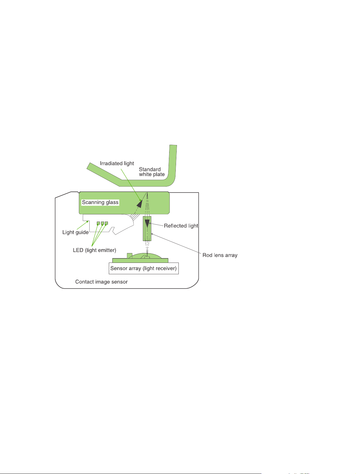
HP LaserJet M1005 MFP unique components
This section presents an overview of the relationships between unique major components in the HP
LaserJet M1005 MFP. This section describes the optical scanning system used in the device.
Scanner functions and operation
The following sections describe how the document scanner functions.
Scanner functions
The contact image sensor (CIS) is the major component of the optical scanning system. The CIS
consists of three LEDs (red, green, and blue), a light guide, the scanning glass, the rod lens array, and
a sensor array. When the CIS scans a document, the CIS moves and the paper is stationary.
Figure 5-6 HP LaserJet M1005 MFP optical system (1 of 2)
The formatter controls the CIS. To begin scanning, the formatter sends a signal to the CIS. The LEDs
illuminate and the light passes through the light guide and scanning glass and strikes the document.
Light that the document reflects passes back through the scanning glass and rod lens array into the
sensor array. The sensor array consists of 5,148 photosensors (468 photosensors on each of 11 sensor
driver circuits). The sensor array collects and amplifies the reflected light and converts it into serial data
in the driver circuits. The CIS sends the data to the formatter for image formation.
56 Chapter 5 Theory of Operation ENWW
Page 73
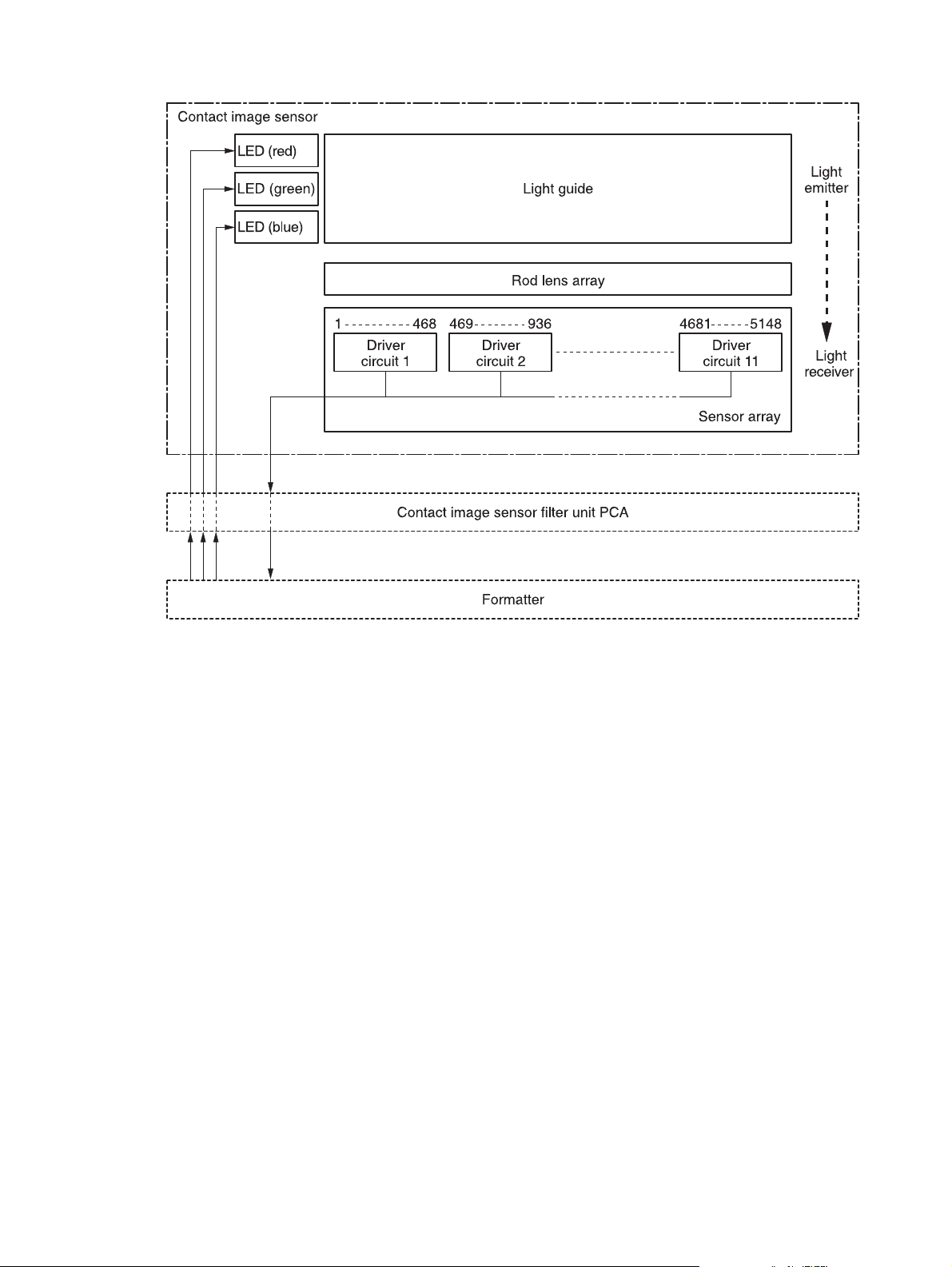
Figure 5-7 HP LaserJet M1005 MFP optical system (2 of 2)
Scanner operation
At startup and periodically at other times, the scanner assembly moves systematically to locate its home
position. It then calibrates to a white strip located under the glass at the right end of the scan tub.
ENWW HP LaserJet M1005 MFP unique components 57
Page 74

58 Chapter 5 Theory of Operation ENWW
Page 75

6 Removal and replacement
This chapter provides information about the following topics.
Removal and replacement strategy
●
ENWW 59
Page 76

Removal and replacement strategy
NOTE Some photos show a device other than the HP LaserJet M1005 MFP. Repair and
replacement procedures in this chapter are for the HP LaserJet M1005 MFP and are not affected
by cosmetic differences (for example, the color of the covers) shown in these photos.
This chapter documents the removal and replacement of field replaceable parts (FRUs) only.
Reinstallation is generally the reverse of removal. Occasionally, notes and hints are included to provide
directions for difficult or critical replacement procedures.
Admonitions
WARNING! Unplug the power cord from the power outlet (at the wall receptacle) before
attempting to service the device. It this warning is not followed, severe injury can result. Certain
functional checks during troubleshooting must be performed with power supplied to the device.
However, the power supply should be disconnected during removal.
Sheet-metal and plastic edges in the device can be sharp. Use caution when servicing this device.
Never operate or service the device with the protective cover removed from the laser/scanner
assembly. The invisible reflected beam can damage your eyes.
CAUTION The device contains components that are sensitive to electrostatic discharge (ESD).
Always perform service work at an ESD-protected workstation. If an ESD-protected workstation
is not available, discharge body static by grasping the print engine chassis before touching an
ESD-sensitive component. Ground the print engine chassis before servicing the device.
CAUTION Do not bend or fold the FFCs during the removal or reinstallation process.
NOTE For service purposes, the upper part of the HP LaserJet M1005 MFP is, in effect, the
"scanner" and the lower part is the "printer". Together, they also act as a photocopier, but the
service description here is simplified by referring to copier functionality only when specifically
necessary.
Tip To install a self-tapping screw, first turn it counterclockwise to align it with the existing thread
pattern, then carefully turn it clockwise to tighten. Do not overtighten.
Required tools
#2 Phillips screwdriver with magnetic tip
●
Small flat-blade screwdriver
●
#8 and #10 torx screwdrivers
●
Needle-nose pliers
●
ESD mat (if available)
●
Penlight (optional)
●
Long flat-blade screwdriver (optional)
●
60 Chapter 6 Removal and replacement ENWW
Page 77

CAUTION Do not use a pozidrive screwdriver or any motorized screwdriver. These can damage
screws or screw threads on the device.
Before performing service
If possible, print a configuration page (to record customer settings) and menu structure report.
●
Troubleshooting tools on page 140.
See
Remove all media from the device and remove the media input tray. See
●
on page 78.
Turn off the power by using the power switch.
●
Unplug the power cord from the wall receptacle.
●
Place the device on an ESD mat, if available. If an ESD-protected workstation is not available,
●
discharge body static and ground the print engine chassis before servicing the device.
Remove the print cartridge.
●
Media input tray
After performing service
Replace the print cartridge.
●
Reload the input tray with media.
●
Restore customer configuration settings.
●
Parts removal order
Use the following diagrams to determine which parts of the device must be removed before servicing.
ENWW Removal and replacement strategy 61
Page 78

Control panel overlay
Control panel
Scanner lid
Scanner assembly
Link assembly and scanner spring
Printer separation pad
Print cartridge
Printer pickup roller
Transfer roller
Media input tray
Printer side covers
Rear cover and fuser cover
Power supply
Scanner assembly
Print-cartridge door
Front cover
Scanner support frame
Engine controller unit
Laser/scanner assembly
Main motor
Fuser assembly
Paper pickup assembly
Front cover
Formatter
Figure 6-1 Parts removal order for the HP LaserJet M1005 MFP
62 Chapter 6 Removal and replacement ENWW
Page 79
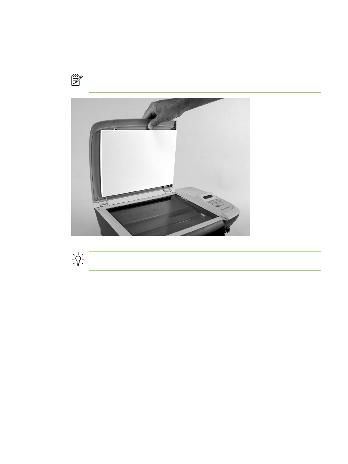
Flatbed lid
1. Open the flatbed lid.
2. Lift the lid up and off of the scanner assembly to remove it.
NOTE The lid must be in the fully opened position to release the hinge pins from the hinge
brackets.
Figure 6-2 Remove the flatbed lid (1 of 2)
Tip When the flatbed lid is reinstalled, make sure that the hinge pins are fully seated in
the hinge brackets on the scanner flatbed assembly.
ENWW Removal and replacement strategy 63
Page 80

Control-panel overlay
Use a small flat blade screwdriver to lift up the control-panel overlay and then remove it.
CAUTION Be careful to not damage the overlay if it will be reinstalled after servicing the device.
Figure 6-3 Remove the control-panel overlay
64 Chapter 6 Removal and replacement ENWW
Page 81

Control panel
Tip Lift up the control-panel overlay to see the screw. See Control-panel overlay on page 64.
Figure 6-4 Remove the control panel (1 of 4)
1. Remove one screw.
Figure 6-5 Remove the control panel (2 of 4)
ENWW Removal and replacement strategy 65
Page 82
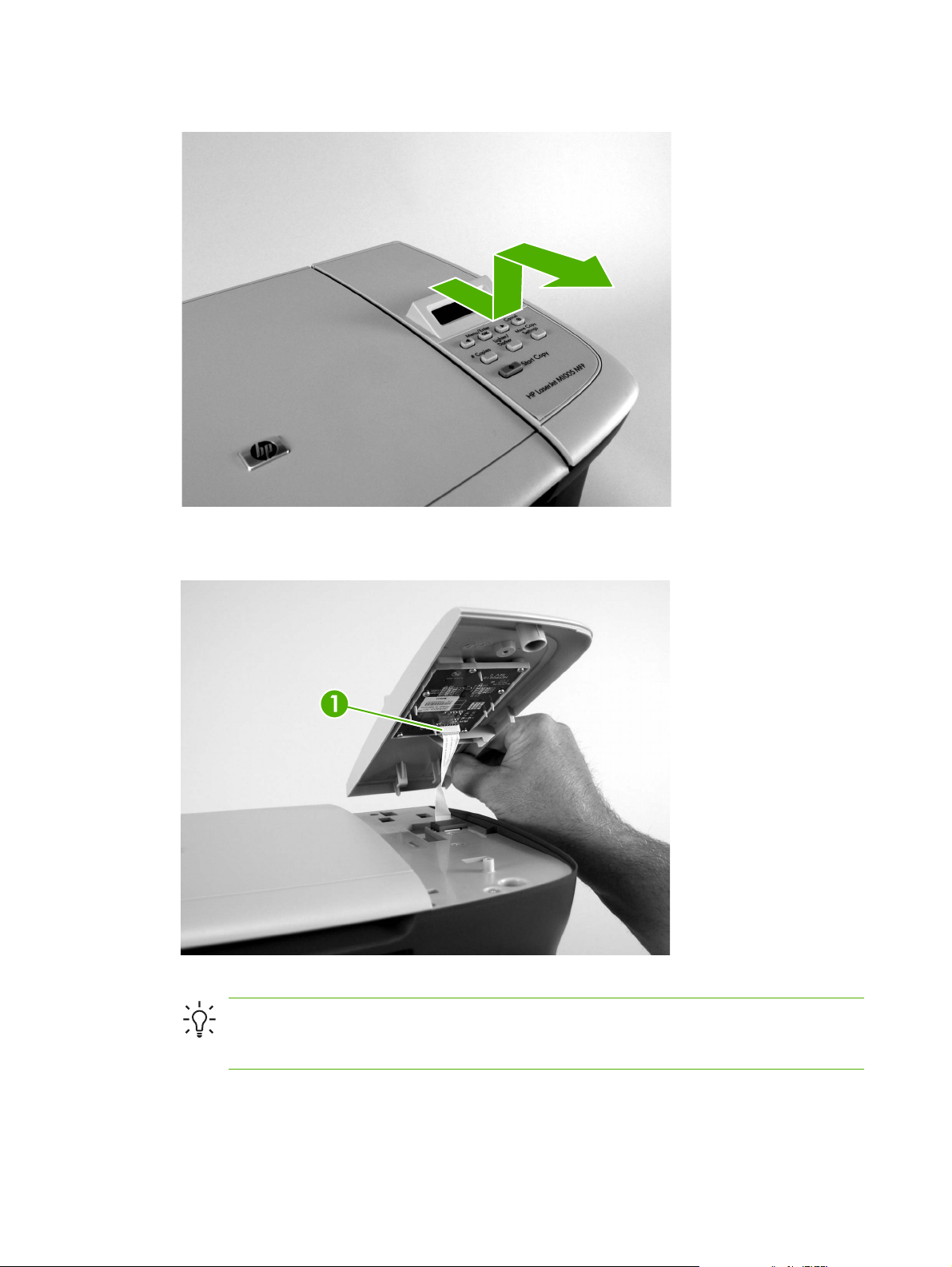
2. Slide the control panel toward you and slightly lift up the control panel.
Figure 6-6 Remove the control panel (3 of 4)
3. Disconnect one flat flexible cable (callout 1) and remove the control panel.
Figure 6-7 Remove the control panel (4 of 4)
Tip When reinstalling the control panel, make sure the rear mounting tabs on the bottom
rear of the control panel engage the holes in the scanner assembly, and then slide the control
panel toward the rear of the device.
66 Chapter 6 Removal and replacement ENWW
Page 83

Scanner assembly
1. Remove the flatbed lid. See Flatbed lid on page 63.
2. Remove one screw (callout 1).
Figure 6-8 Remove the scanner assembly (1 of 11)
3. Gently pry the side cover away from the device chassis.
Figure 6-9 Remove the scanner assembly (2 of 11)
ENWW Removal and replacement strategy 67
Page 84

4. Release the side cover bottom locking tab and remove the cover.
Figure 6-10 Remove the scanner assembly (3 of 11)
5. Disconnect two FFCs (callout 2).
Figure 6-11 Remove the scanner assembly (4 of 11)
68 Chapter 6 Removal and replacement ENWW
Page 85

6. Push the print-cartridge-door button and raise the scanner assembly.
Figure 6-12 Remove the scanner assembly (5 of 11)
7. Remove the shield and the FFCs from the guide (callout 3).
NOTE The screw (callout 4) that fastens the shield to the device chassis does not need
to be removed.
Figure 6-13 Remove the scanner assembly (6 of 11)
ENWW Removal and replacement strategy 69
Page 86

8. Release the tab on the gear-drive arm bracket and carefully flex it away from the scanner assembly.
Figure 6-14 Remove the scanner assembly (7 of 11)
9. Pull the bracket toward the right side of the device until its mounting tabs clear the holes in the
scanner assembly.
Figure 6-15 Remove the scanner assembly (8 of 11)
70 Chapter 6 Removal and replacement ENWW
Page 87
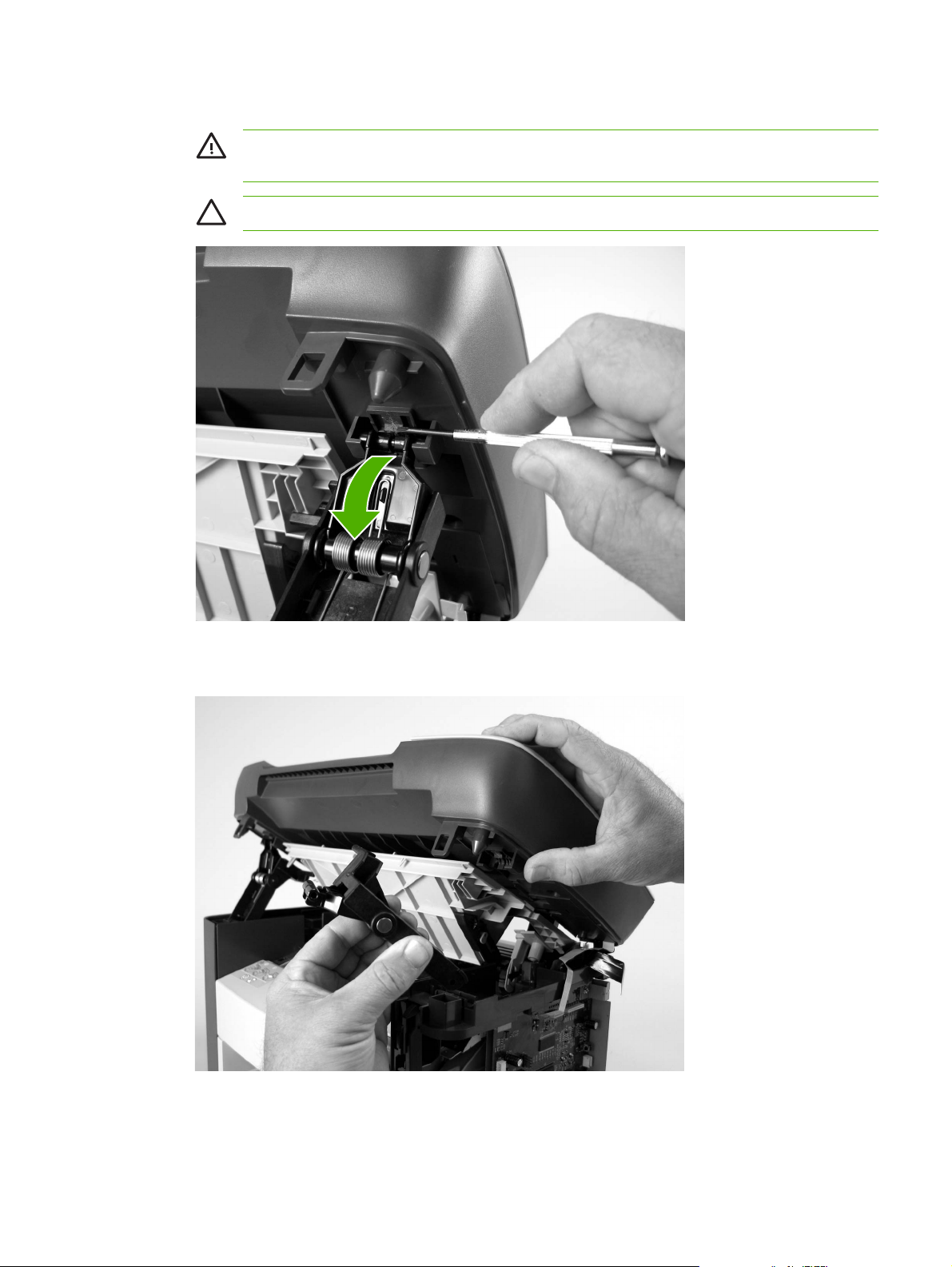
10. Use a small flat-blade screwdriver to release the hinge tabs on each front hinge (right side shown).
WARNING! When the front hinges are disengaged, the scanner assembly can easily fall
off of the device base if it is rotated too far toward the back of the product.
CAUTION Do not push too hard on the link tabs or the tabs might break.
Figure 6-16 Remove the scanner assembly (9 of 11)
11. Remove the hinges (right side shown).
Figure 6-17 Remove the scanner assembly (10 of 11)
ENWW Removal and replacement strategy 71
Page 88

12. Rotate the scanner assembly toward the rear of the product until the rear hinges clear the chassis
hinge pins. Lift the scanner assembly up and off of the device base.
Figure 6-18 Remove the scanner assembly (11 of 11)
72 Chapter 6 Removal and replacement ENWW
Page 89

Device separation pad
NOTE Some photos show a device other than the HP LaserJet M1005 MFP. Repair and
replacement procedures in this chapter are for the HP LaserJet M1005 MFP and are not affected
by cosmetic differences (for example, the color of the covers) shown in these photos.
1. At the back of the device, remove two screws (callout 1).
Figure 6-19 Remove the device separation pad (1 of 2)
2. Remove the device separation pad and frame.
Figure 6-20 Remove the device separation pad (2 of 2)
ENWW Removal and replacement strategy 73
Page 90
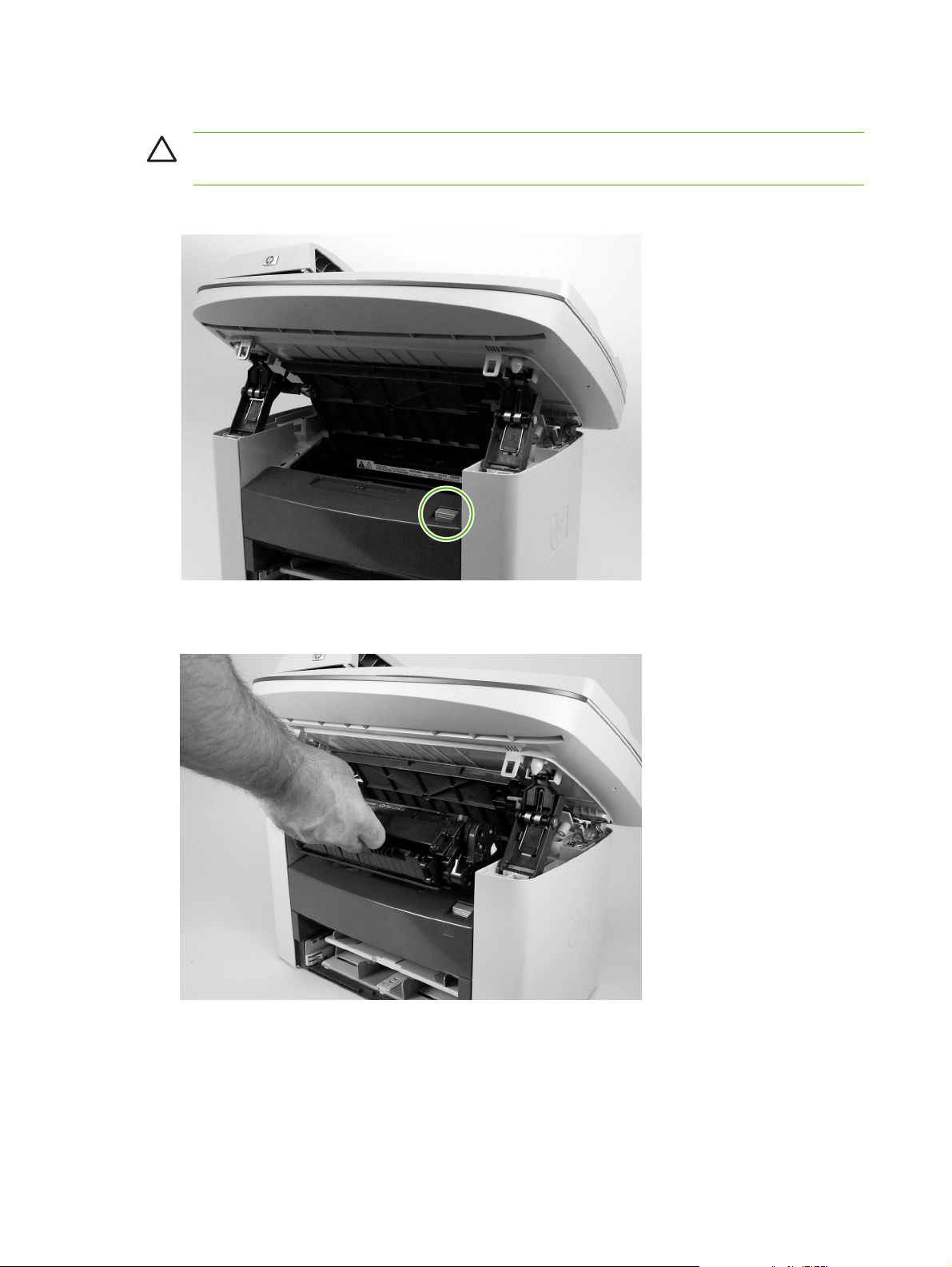
Print cartridge
CAUTION To prevent damage, do not expose the print cartridge to direct or bright light. Cover
it with a piece of paper.
1. Push the print-cartridge-door button to release the print-cartridge door.
Figure 6-21 Remove the print cartridge (1 of 2)
2. Pull the print cartridge up and out of the device.
Figure 6-22 Remove the print cartridge (2 of 2)
74 Chapter 6 Removal and replacement ENWW
Page 91

Device pickup roller
1. Remove the print cartridge and locate the device pickup roller. See Print cartridge on page 74.
Figure 6-23 Remove the device pickup roller (1 of 5)
2. Gently release the small, white tabs on each side of the pickup roller by pushing them away from
the roller, and then rotate the roller away from the mounting frame.
CAUTION Do not touch the black-sponge transfer roller inside the device. Touching the
transfer roller can damage the device.
Use gentle pressure to release the small white tabs to avoid breaking them.
Figure 6-24 Remove the device pickup roller (2 of 5)
ENWW Removal and replacement strategy 75
Page 92

3. Gently pull the roller up and out of the device.
Figure 6-25 Remove the device pickup roller (3 of 5)
4. Circular and rectangular pegs on each side of the pickup roller fit into corresponding slots on the
pickup-roller mounting frame to prevent the roller from being incorrectly installed. Position the
replacement pickup roller in the slots on the pickup-roller frame.
Figure 6-26 Remove the device pickup roller (4 of 5)
76 Chapter 6 Removal and replacement ENWW
Page 93

5. Rotate the top of the pickup roller into position until the white tabs on each side of the roller snap
into place.
Figure 6-27 Remove the device pickup roller (5 of 5)
ENWW Removal and replacement strategy 77
Page 94
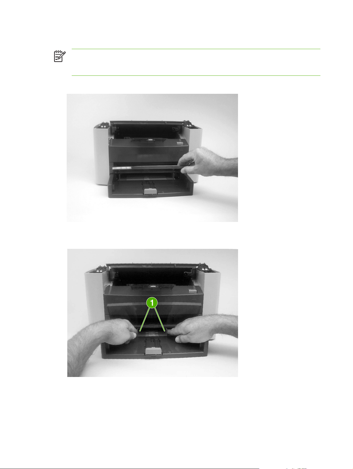
Media input tray
NOTE Some photos show a device other than the HP LaserJet M1005 MFP. Repair and
replacement procedures in this chapter are for the HP LaserJet M1005 MFP and are not affected
by cosmetic differences (for example, the color of the covers) shown in these photos.
1. Open the media input tray lid.
Figure 6-28 Remove the media input tray (1 of 3)
2. Slide the adjustable media guides (callout 1) to the center of the tray.
Figure 6-29 Remove the media input tray (2 of 3)
78 Chapter 6 Removal and replacement ENWW
Page 95
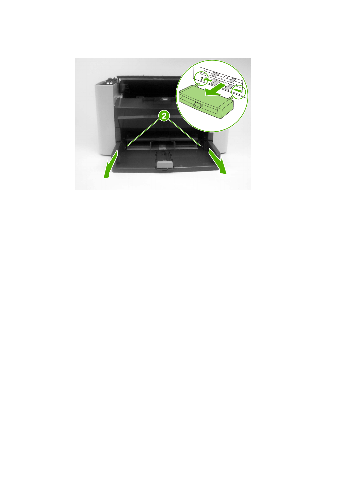
3. Depress the pickup-tray locking tabs (callout 2) to release the media input tray, and then pull it out
and away from the device.
Figure 6-30 Remove the media input tray (3 of 3)
ENWW Removal and replacement strategy 79
Page 96

Transfer roller
CAUTION Do not touch the black-sponge portion of the transfer roller. Skin oils deposited on
the transfer roller might cause print-quality problems.
Be very careful not to break the paper guide that is removed during replacement of the transfer
roller. Because the paper guide is not a FRU, the entire device will have to be replaced.
1. Open the print-cartridge door and remove the print cartridge.
2. Release the two locking tabs on the paper guide and rotate the guide up.
Figure 6-31 Remove the transfer roller (1 of 3)
80 Chapter 6 Removal and replacement ENWW
Page 97

3. The clamps on the paper guide fit over the bearings on each end of the transfer roller. Do not touch
the black-sponge portion of the transfer roller. Grasp the right end of the paper guide and pull the
clamp off the bearing on the right side of the transfer roller. Then slide the clamp slightly to the
right, and the left clamp will slide off the left bearing.
Figure 6-32 Remove the transfer roller (2 of 3)
4. Squeeze the two small tabs on the transfer roller.
Figure 6-33 Remove the transfer roller (3 of 3)
ENWW Removal and replacement strategy 81
Page 98

Device side covers
NOTE Some photos show a device other than the HP LaserJet M1005 MFP. Repair and
replacement procedures in this chapter are for the HP LaserJet M1005 MFP and are not affected
by cosmetic differences (for example, the color of the covers) shown in these photos.
NOTE The procedure for removing the right-side and left-side covers is identical, with the
exception of the location of the screw that fastens the cover to the device. The right-side cover
is shown in the following procedure.
1. Remove one screw (callout 1; the right-side cover uses a black screw). Callout 2 is on the left-side
cover.
Figure 6-34 Remove the device side covers (1 of 3)
82 Chapter 6 Removal and replacement ENWW
Page 99

2. Release the locking tabs on the upper-back (callout 2).
Figure 6-35 Remove the device side covers (2 of 3)
3. Release the bottom tab (callout 3).
CAUTION When removing the left-side cover hang the device off of the table to gain
access to the bottom tab. This prevents the I/O shield from being damaged if the right-side
cover is off and the device is tilted too far up.
Figure 6-36 Remove the device side covers (2 of 3)
ENWW Removal and replacement strategy 83
Page 100

4. Slightly rotate the back-side of the right cover away from the device, and then slide it toward the
front of the device to release it.
Figure 6-37 Remove the device side covers (3 of 3)
Tip When reinstalling the device side covers, hook the front of the cover onto the device
and rotate the rear of the cover over the device chassis.
84 Chapter 6 Removal and replacement ENWW
 Loading...