

Page 1
LASERJET ENTERPRISE 500 MFP
LASERJET ENTERPRISE FLOW MFP M525
Troubleshooting Manual
2
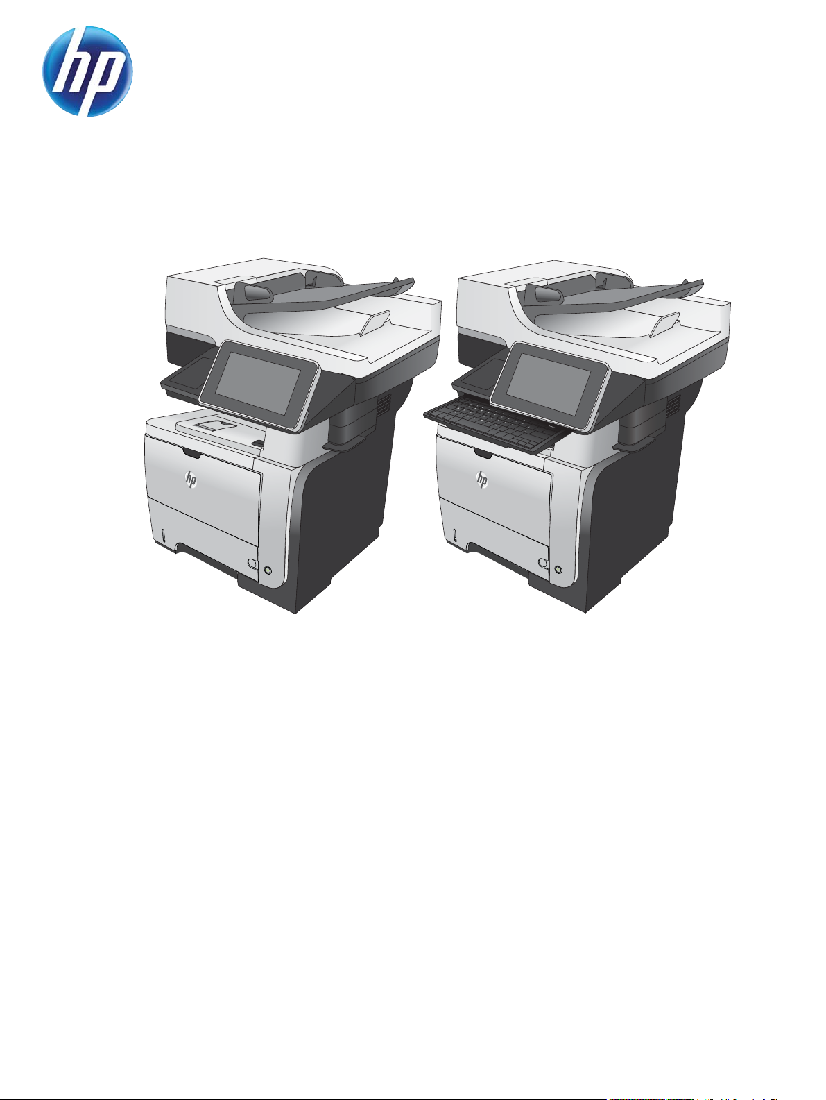
M525
2
M525c
Page 2

Page 3

HP LaserJet Enterprise 500 MFP M525
and HP LaserJet Enterprise flow MFP
M525
Troubleshooting Manual
Page 4

Copyright and License
© 2012 Copyright Hewlett-Packard
Development Company, L.P.
Trademark Credits
®
, Acrobat®, and PostScript® are
Adobe
trademarks of Adobe Systems Incorporated.
Reproduction, adaptation, or translation
without prior written permission is
prohibited, except as allowed under the
copyright laws.
The information contained herein is subject
to change without notice.
The only warranties for HP products and
services are set forth in the express warranty
statements accompanying such products and
services. Nothing herein should be
construed as constituting an additional
warranty. HP shall not be liable for technical
or editorial errors or omissions contained
herein.
Edition 2, 11/2012
Part number: CF116-90901
Microsoft®, Windows®, Windows® XP,
and Windows Vista® are U.S. registered
trademarks of Microsoft Corporation.
ENERGY STAR and the ENERGY STAR mark
are registered U.S. marks.
Page 5

Conventions used in this guide
TIP: Tips provide helpful hints or shortcuts.
NOTE: Notes provide important information to explain a concept or to complete a task.
CAUTION: Cautions indicate procedures that you should follow to avoid losing data or damaging
the product.
WARNING! Warnings alert you to specific procedures that you should follow to avoid personal
injury, catastrophic loss of data, or extensive damage to the product.
ENWW iii
Page 6

iv Conventions used in this guide ENWW
Page 7

Table of contents
1 Theory of operation .......................................................................................................... 1
Basic operation ........................................................................................................................ 2
Major systems ........................................................................................................... 2
Product block diagram ............................................................................................... 2
Sequence of operation ............................................................................................... 3
Normal sequence of operation ..................................................................... 3
Formatter-control system ............................................................................................................ 4
Auto on/Auto off mode .............................................................................................. 4
Input/output ............................................................................................................. 6
CPU ........................................................................................................................ 6
Memory ................................................................................................................... 6
Firmware ................................................................................................... 6
Nonvolatile memory ................................................................................... 6
PJL overview ............................................................................................................. 6
PML ......................................................................................................................... 7
Control panel ........................................................................................................... 7
Engine-control system ................................................................................................................ 8
Motors, fans, clutches, solenoids, switches, and sensors ................................................. 9
DC controller operations .......................................................................................... 16
Fuser-control circuit .................................................................................................. 18
Fuser failure detection ............................................................................... 19
Fuser temperature control .......................................................................... 20
Fuser protective function ............................................................................ 21
Low-voltage power supply ........................................................................................ 22
Overcurrent/overvoltage protection ............................................................ 23
High-voltage power supply ....................................................................................... 24
Formatter ............................................................................................................... 25
Formatter heartbeat LED ............................................................................ 25
Laser/scanner system .............................................................................................. 26
Laser failure detection ............................................................................... 27
Image-formation system ........................................................................................................... 28
Electrophotographic process ..................................................................................... 28
ENWW v
Page 8

Image formation process .......................................................................................... 29
Latent-image formation stage ..................................................................... 30
Primary charging ...................................................................... 30
Laser beam exposure ................................................................. 30
Developing stage ..................................................................................... 31
Toner cartridge ......................................................................... 31
Transfer stage .......................................................................................... 32
Fusing stage ............................................................................. 32
Cleaning stage ......................................................................... 33
Toner detection ....................................................................................................... 34
Pickup, feed, and delivery system ............................................................................................. 35
Paper trays ............................................................................................................. 35
Photo sensors and switches ...................................................................................... 36
Solenoids and clutches ............................................................................................ 38
Tray 1 or Tray 2 .................................................................................................................... 40
Pickup and feed unit ................................................................................................ 40
Cassette paper size detection/cassette paper detection ................................ 40
Cassette pickup ........................................................................................ 40
Tray 1 paper pickup ................................................................................................ 40
Paper pickup and feed ............................................................................................ 41
Jam detection ......................................................................................................... 42
Additional tray ...................................................................................................................... 43
Tray driver PCA ...................................................................................................... 43
Paper pickup and feed ............................................................................................ 44
Paper level and size detection .................................................................................. 45
Jam detection ......................................................................................................... 45
Scanning/image capture system .............................................................................................. 46
Control panel ......................................................................................................... 46
Scanner ................................................................................................................. 46
Document feed system ............................................................................................. 46
Document feeder operation (standard model) .............................................. 47
Sensors in the document feeder (standard model) .......................... 47
Document feeder paper path (standard model) ............................. 48
Document feeder simplex operation (standard model) .................... 49
Document feeder duplex operation (standard model) ..................... 50
Document feeder operation (M525c model) ................................................ 53
Sensors in the document feeder (M525c model) ............................ 53
Document feeder paper path (M525c model) ............................... 55
Document feeder simplex operation (M525c model) ...................... 56
Document feeder e-duplex operation (M525c model) ..................... 57
Frontside and backside background selector (M525c model) .......... 57
vi ENWW
Page 9

Document feeder operation (standard model and the M525c model) .............. 58
Deskew operation ..................................................................... 58
Document feeder hinges ............................................................. 59
Stapler .................................................................................................................................. 61
2 Solve problems ............................................................................................................... 63
Solve problems checklist ......................................................................................................... 64
Menu map ............................................................................................................................ 66
Preboot menu options ............................................................................................................. 67
Current settings pages ............................................................................................................ 74
Troubleshooting process .......................................................................................................... 75
Determine the problem source ................................................................................... 75
Troubleshooting flowchart ......................................................................... 75
Power subsystem ..................................................................................................... 76
Power-on checks ...................................................................................... 76
Power-on troubleshooting overview .............................................. 76
Control-panel checks ............................................................................................... 77
Scanning subsystem ................................................................................................ 79
Tools for troubleshooting ......................................................................................................... 80
Individual component diagnostics .............................................................................. 80
LED diagnostics ........................................................................................ 80
Understand lights on the formatter ............................................... 80
Engine diagnostics ................................................................................... 83
Engine-test button ...................................................................... 83
Paper path test ......................................................................................... 85
Paper path sensors test ............................................................................. 85
Manual sensor test ................................................................................... 87
SW501 Cartridge door switch test .............................................. 89
PS8001 Rear door sensor test ..................................................... 90
PS215 Top (Top-of-Page) sensor test ............................................ 91
PS225 Paper width 1 sensor test ................................................. 92
PS2 Fuser output sensor test ........................................................ 93
PS502 Duplexer refeed sensor test .............................................. 94
PS1 Rear bin sensor test ............................................................. 95
PS4 Output bin full sensor test ..................................................... 96
PS8008 Tray 3 Feed sensor ....................................................... 97
PS8008 Tray 4 Feed sensor ....................................................... 98
Tray/bin manual sensor test ...................................................................... 99
PS205 Tray 1 Paper sensor test ................................................. 101
PS3 Tray 2 Paper sensor test ..................................................... 102
SW235 Tray 2 Cassette sensor test ........................................... 103
ENWW vii
Page 10

PS4 Output bin full sensor test ................................................... 104
PS451 Tray 3 paper sensor test ................................................ 105
PS461 Tray 3 cassette sensor test .............................................. 106
PS451 Tray 4 paper sensor test ................................................ 107
PS461 Tray 4 cassette sensor test .............................................. 108
Print/stop test ........................................................................................ 108
Component tests ..................................................................................... 109
Control-panel tests ................................................................... 109
Half self-test ............................................................................ 110
Drum rotation test check ........................................................... 110
Component test (special-mode test) ............................................ 110
Diagrams ............................................................................................................. 112
Block diagrams ...................................................................................... 112
Location of connectors ............................................................................ 114
DC controller connections ......................................................... 114
Formatter connections .............................................................. 115
Plug/jack locations ................................................................................. 116
Locations of major components ................................................................ 116
General timing charts ............................................................................. 120
Circuit diagrams .................................................................................... 121
Internal print-quality test pages ................................................................................ 123
Clean the paper path ............................................................................. 123
Set up an auto cleaning page ................................................... 123
Print a configuration page ....................................................................... 124
Configuration page ................................................................. 124
HP embedded Jetdirect page .................................................... 125
Finding important information on the configuration pages ............ 126
Print quality troubleshooting tools ............................................................................ 127
Repetitive defects ruler ............................................................................ 127
Control panel menus .............................................................................................. 128
Administration menu ............................................................................... 128
Reports menu .......................................................................... 128
General Settings menu ............................................................. 129
Copy Settings menu ................................................................. 136
Scan/Digital Send Settings menu .............................................. 144
Fax Settings menu ................................................................... 155
General Print Settings menu ...................................................... 169
Default Print Options menu ....................................................... 171
Display Settings menu .............................................................. 172
Manage Supplies menu ........................................................... 175
Manage Trays menu ................................................................ 177
viii ENWW
Page 11

Network Settings menu ............................................................ 179
Troubleshooting menu .............................................................. 193
Device Maintenance menu ...................................................................... 196
Backup/Restore menu .............................................................. 196
Calibration/Cleaning menu ...................................................... 197
USB Firmware Upgrade menu ................................................... 199
Service menu .......................................................................... 199
Interpret control-panel messages ............................................................................. 200
Control-panel message types ................................................................... 200
Control-panel messages .......................................................................... 200
10.0X.Y0 Supply memory error ................................................ 200
10.23.50 ............................................................................... 201
10.23.51 ............................................................................... 201
10.23.52 ............................................................................... 201
10.23.70 Printing Past Very Low ............................................... 201
10.XX.34 Used Supply In Use ................................................... 202
10.XX.40 Genuine HP Supplies Installed .................................... 202
10.XX.40 Unsupported Supply In Use ........................................ 202
10.XX.70 Printing Past Very Low ............................................... 202
10.YY.15 Install Supply10.YY.15 Install Supply .......................... 203
11.00.YY Internal clock error To continue, touch “OK” ................ 203
13.A3.D3 or 13.A4.D4 ........................................................... 204
13.A3.D4 .............................................................................. 204
13.A3.FF or 13.A4.FF ............................................................. 205
13.B2.D1 ............................................................................... 205
13.B2.D2 ............................................................................... 206
13.B2.DD .............................................................................. 207
13.B2.XX ............................................................................... 208
13.B2.XX ............................................................................... 209
13.B9.FF ................................................................................ 209
13.B9.XX ............................................................................... 210
13.B9.XX ............................................................................... 211
13.B9.XX ............................................................................... 212
13.BA.EE or 13.DA.EE ............................................................ 212
13.D3.FF or 13.B2.FF .............................................................. 213
13.D3.XX ............................................................................... 214
13.E1.XX ............................................................................... 215
20.00.00 Insufficient memory: <Device> To continue, touch “OK” 216
21.00.00 Page too complex To continue, touch “OK” ................. 216
30.01.23 Scanner calibration failure ........................................ 216
30.01.36 Upgrade Error Try downloading upgrade again .......... 216
ENWW ix
Page 12

30.01.43 Scan memory failure To continue turn off then on ......... 217
30.01.YY Scanner failure To continue turn off then on ................. 217
30.WX.YZ Scanner fan failure To continue turn off then on .......... 218
31.01.47 Document feeder not detected .................................... 218
31.03.22 Scanner calibration failure ........................................ 218
31.13.03 Document feeder pick error ....................................... 218
31.WX.10 Scanner failure To continue turn off then on ................ 219
31.WX.15 Jam in document feeder ........................................... 219
33.WX.YZ Used board/disk installed ........................................ 219
40.00.01 USB I/O buffer overflow To continue, touch “OK” ........ 220
41.02.00 Error ....................................................................... 220
41.03.YZ Unexpected size in Tray <X> ..................................... 220
41.03.YZ Unexpected size in Tray <X> To use another tray, touch
"Options" ............................................................................... 221
49.XX.YY Error To continue turn off then on ................................ 221
50.WX.YZ Fuser error To continue turn off then on ...................... 222
51.00.YY Error To continue turn off then on ................................ 225
52.XX.00 To continue turn off then on ........................................ 226
54.XX.YY Error ....................................................................... 226
55.XX.YY DC Controller error To continue turn off then on ............ 226
56.00.YY Error To continue turn off then on ................................ 227
57.00.0X Error ....................................................................... 227
58.00.04 Error To continue turn off then on ............................... 227
59.00.00 Error To continue turn off then on ............................... 227
59.00.20 Error To continue turn off then on ............................... 227
62.00.00 No system To continue turn off then on ........................ 228
69.X ERROR To continue, touch “OK” ........................................ 228
70.00.00 Error To continue turn off then on ............................... 228
81.WX.00 Wireless Network Error To continue turn off then on .... 228
81.WX.YZ Embedded JetDirect Error To continue turn off then on .. 229
89.19.5C Error ....................................................................... 229
98.00.01 or 98.01.00 Corrupt data in firmware volume ............. 229
98.00.02 Corrupt data in solutions volume ................................ 230
98.00.03 Corrupt data in configuration volume .......................... 230
98.00.04 Corrupt data in job data volume ................................ 230
99.00.01 Upgrade not performed file is corrupt ......................... 230
99.00.02 Upgrade not performed timeout during receive ............ 230
99.00.03 Upgrade not performed error writing to disk ................ 231
99.00.04 Upgrade not performed timeout during receive ............ 231
99.00.05 Upgrade not performed timeout during receive ............ 231
99.00.06 Upgrade not performed error reading upgrade ............ 231
x ENWW
Page 13

99.00.07 Upgrade not performed error reading upgrade ............ 232
99.00.08 Upgrade not performed error reading upgrade ............ 232
99.00.09 Upgrade canceled by user ........................................ 232
99.00.10 Upgrade canceled by user ........................................ 232
99.00.11 Upgrade canceled by user ........................................ 232
99.00.12 Upgrade not performed the file is invalid .................... 233
99.00.14 Upgrade not performed the file is invalid .................... 233
99.00.2X ............................................................................... 233
99.09.60 Unsupported Disk ..................................................... 234
99.09.61 Unsupported disk ..................................................... 234
99.09.64 Disk malfunction ....................................................... 234
99.09.65 Disk data error ......................................................... 234
99.09.66 No disk data installed ............................................... 235
99.09.67 Disk is not bootable please download firmware ........... 235
99.XX.YY ............................................................................... 235
<Binname> full Remove all paper from bin ................................. 235
[File System] device failure To clear press OK ............................. 235
[File System] file operation failed To clear press OK .................... 236
[File System] file system is full To clear press OK ......................... 236
[File System] is not initialized .................................................... 236
[File System] is write protected .................................................. 236
A second USB wireless networking accessory has been detected . . 236
Accept bad signature ............................................................... 237
Bad optional tray connection .................................................... 237
Black Cartridge low ................................................................. 237
Black Cartridge very low .......................................................... 237
Black Cartridge very low To continue, touch “OK” ...................... 238
Canceling <jobname> ............................................................. 238
Cartridge ship mode ................................................................ 238
Checking paper path ............................................................... 238
Chosen personality not available To continue, touch “OK” ........... 238
Clean the rollers ...................................................................... 239
Cleaning disk <X>% complete Do not power off ......................... 239
Cleaning do not grab paper ..................................................... 239
Cleaning... ............................................................................. 239
Clearing event log ................................................................... 240
Clearing paper path ................................................................ 240
Close inner flap in duplexer ...................................................... 240
Close rear door ...................................................................... 240
Close rear door Or touch OK to print to the rear bin ................... 240
Close top cover ....................................................................... 241
ENWW xi
Page 14

Creating cleaning page ........................................................... 241
Data received ......................................................................... 241
Digital send communication error .............................................. 241
Disk full Delete stored jobs ........................................................ 242
Disk low Delete stored jobs ....................................................... 242
Document feeder bin full .......................................................... 242
Document feeder is empty ........................................................ 242
Document Feeder Kit low .......................................................... 242
Document Feeder Kit very low ................................................... 243
Document Feeder Kit very low To continue, touch “OK” ............... 243
Document feeder top cover open ............................................... 243
Event log is empty ................................................................... 243
Expected drive missing ............................................................. 243
Fax is disabled – ignoring call .................................................. 244
Flatbed cover open .................................................................. 244
HP Secure Hard Drive disabled ................................................. 244
Incompatible <supply> ............................................................. 244
Incompatible supplies .............................................................. 244
Initializing scanner, please wait ................................................ 245
Initializing... ........................................................................... 245
Install Black Cartridge .............................................................. 245
Install Fuser Unit ...................................................................... 245
Install supplies ........................................................................ 246
Internal disk device failure To clear touch “Clear” ....................... 246
Internal disk file operation failed To clear touch “Clear” ............... 246
Internal disk file system is full To clear touch “Clear” .................... 246
Internal disk is write protected To clear touch “Clear” .................. 246
Internal disk not found ............................................................. 247
Internal disk not functional ........................................................ 247
Internal disk not initialized To clear touch “Clear” ....................... 247
Internal disk spinning up .......................................................... 247
Load Tray 1 [Type] [Size] ......................................................... 247
Load Tray 1 [Type] [Size] To continue, touch “OK” ...................... 247
Load Tray <X>: [Size] .............................................................. 248
Load Tray <X>: [Size] To continue, touch “OK” .......................... 248
Load Tray <X>: [Size] To use another tray, touch "Options" ......... 248
Load Tray <X>: [Type], [Size] ................................................... 249
Load Tray <X>: [Type], [Size] To use another tray, touch
"Options" ............................................................................... 249
Manually feed output stack Then touch "OK" to print second sides 249
Manually feed: [Size] .............................................................. 249
xii ENWW
Page 15

Manually feed: [Size] To continue, touch “OK” ........................... 250
Manually feed: [Size] To use another tray, touch "Options" .......... 250
Manually feed: [Type], [Size] To continue, touch “OK” ................ 250
Manually feed: [Type], [Size] To use another tray, touch
"Options" ............................................................................... 251
No job to cancel ..................................................................... 251
Open rear door ...................................................................... 251
Output Bin full ......................................................................... 251
Paperless mode ....................................................................... 251
Printing Engine Test... .............................................................. 252
Printing stopped To continue, touch “OK” ................................... 252
Processing digital send job ....................................................... 252
RAM Disk device failure To clear touch “Clear” .......................... 252
RAM Disk file operation failed To clear touch “Clear” .................. 252
RAM Disk file system is full To clear touch “Clear” ....................... 252
RAM Disk is write protected To clear touch “Clear” ..................... 253
RAM Disk not initialized To clear touch “Clear” .......................... 253
Remove cartridge lock ............................................................. 253
Remove the toner cartridge ....................................................... 253
Replace Black Cartridge ........................................................... 253
Replace Document Feeder Kit ................................................... 254
Replace supplies ..................................................................... 254
Roller cleaning is recommended ................................................ 254
ROM disk device failed To clear touch “Clear” ........................... 255
ROM disk file operation failed To clear touch “Clear” .................. 255
ROM disk file system is full To clear touch “Clear” ....................... 255
ROM disk is write protected To clear touch “Clear” ..................... 255
ROM disk not initialized To clear touch “Clear” .......................... 255
Size mismatch in Tray <X> ....................................................... 256
Standard bin full Remove all paper from bin ............................... 256
Supplies low ........................................................................... 256
Supplies very low To continue, touch “OK” ................................. 256
Supply memory warning .......................................................... 257
Tray <X> empty: [Size] ............................................................ 257
Tray <X> empty: [Type], [Size] ................................................. 257
Tray <X> open ........................................................................ 257
Tray <X> overfilled Remove excess paper .................................. 258
Tray <X> overfilled To use another tray, touch "Options" ............. 258
Type mismatch Tray <X> .......................................................... 258
Unable to cancel firmware update job ....................................... 259
Unable to install the firmware ................................................... 259
ENWW xiii
Page 16

Unsupported drive installed ...................................................... 259
Unsupported supply in use ........................................................ 259
Unsupported supply installed .................................................... 260
Unsupported supply installed To continue, touch “OK” ................. 260
Unsupported tray configuration ................................................. 260
Unsupported USB accessory detected Remove USB accessory ....... 260
Upgrade complete To continue turn off then on ........................... 261
USB accessory needs too much power Remove USB and turn off
then on .................................................................................. 261
USB accessory not functional .................................................... 261
USB hubs are not fully supported Some operations may not work
properly ................................................................................. 261
USB is write protected To clear touch “Clear” ............................. 261
USB not initialized To clear touch “Clear” .................................. 262
USB storage accessory removed Clearing any associated data ..... 262
USB storage device failure To clear touch “Clear” ....................... 262
USB storage file operation failed To clear touch “Clear” .............. 262
USB storage file system is full To clear touch “Clear” ................... 262
Used supply in use .................................................................. 262
Used supply installed To continue, touch “OK” ............................ 263
Warming up scanner ............................................................... 263
Wireless Configuration Mode ................................................... 263
Wireless is not configured ........................................................ 263
Event log messages ............................................................................................... 264
Print or view an event log ........................................................................ 265
Clear an event log .................................................................................. 265
Event log message table .......................................................................... 266
Clear jams .......................................................................................................................... 275
Auto-navigation for clearing jams ............................................................................ 275
Common causes of jams ........................................................................................ 275
Jam locations ........................................................................................................ 276
Clear jams in the document feeder .......................................................................... 277
Clear jams in the document feeder (M525c model) ................................................... 279
Clear jams in the output-bin area ............................................................................ 280
Clear jams in Tray 1 .............................................................................................. 281
Clear jams in Tray 2 or an optional 500-sheet tray ................................................... 284
Clear jams in the toner-cartridge area ...................................................................... 287
Clear jams in the rear-door and the fuser area .......................................................... 289
Clear jams in the duplexer ..................................................................................... 292
Jam causes and solutions ....................................................................................... 298
Solve paper-handling problems .............................................................................................. 302
xiv ENWW
Page 17

The product picks up multiple sheets of paper ........................................................... 302
The product does not pick up paper ........................................................................ 302
The document feeder jams, skews, or picks up multiple sheets of paper ....................... 303
Use manual print modes ....................................................................................................... 304
Solve image-quality problems ................................................................................................ 307
Image defect examples .......................................................................................... 307
Clean the product ................................................................................................................ 315
Clean the control-panel display ............................................................................... 315
Print a cleaning page ............................................................................................ 315
Check the scanner glass for dirt or smudges ............................................................. 316
Clean the pickup rollers and separation pad in the document feeder ........................... 318
Solve performance problems ................................................................................................. 320
Solve connectivity problems ................................................................................................... 321
Solve USB connection problems .............................................................................. 321
Solve wired network problems ................................................................................ 321
The product has a poor physical connection. ............................................. 321
The computer is using the incorrect IP address for the product ...................... 321
The computer is unable to communicate with the product ............................ 322
The product is using incorrect link and duplex settings for the network .......... 322
New software programs might be causing compatibility problems ................ 322
The computer or workstation might be set up incorrectly .............................. 322
The product is disabled, or other network settings are incorrect .................... 322
Service mode functions ......................................................................................................... 323
Service menu ........................................................................................................ 323
Product resets ....................................................................................................... 326
Restore factory-set defaults ....................................................................... 326
Restore the service ID .............................................................................. 326
Product cold reset ................................................................................... 327
Format Disk and Partial Clean functions ................................................................... 327
Active and repository firmware locations ................................................... 327
Partial Clean ......................................................................................... 328
Execute a 3 Partial Clean ......................................................... 328
Format Disk ........................................................................................... 329
Execute a 2 Format Disk ........................................................... 329
Solve fax problems ............................................................................................................... 331
Checklist for solving fax problems ........................................................................... 331
What type of phone line are you using? .................................................... 331
Are you using a surge-protection device? .................................................. 331
Are you using a phone company voice-messaging service or an answering
machine? .............................................................................................. 332
Does your phone line have a call-waiting feature? ...................................... 332
ENWW xv
Page 18

Check fax accessory status ..................................................................................... 333
General fax problems ............................................................................................ 334
Use Fax over VoIP networks .................................................................................... 335
Problems with receiving faxes ................................................................................. 336
Problems with sending faxes ................................................................................... 338
Fax error codes .................................................................................................... 340
Fax error messages on the product control panel ...................................................... 340
Send-fax messages ................................................................................. 341
Receive-fax messages ............................................................................. 342
Service settings ..................................................................................................... 343
Settings in the Troubleshooting menu ........................................................ 343
Product upgrades ................................................................................................................. 344
Determine the installed revision of firmware .............................................................. 344
Perform a firmware upgrade ................................................................................... 344
Embedded Web Server ........................................................................... 344
USB storage device (Preboot menu) .......................................................... 345
USB storage device (control-panel menu) ................................................... 346
Web Jetadmin (WJA) .............................................................................. 347
Upload firmware files to WJA ................................................... 347
Appendix A Service and support ..................................................................................... 349
Hewlett-Packard limited warranty statement ............................................................................. 350
HP's Premium Protection Warranty: LaserJet toner cartridge limited warranty statement ................. 352
HP policy on non-HP supplies ................................................................................................ 353
HP anticounterfeit Web site ................................................................................................... 354
Data stored on the toner cartridge .......................................................................................... 355
End User License Agreement .................................................................................................. 356
OpenSSL ............................................................................................................................. 359
Customer self-repair warranty service ..................................................................................... 360
Customer support ................................................................................................................. 361
Appendix B Product specifications ................................................................................... 363
Physical specifications .......................................................................................................... 364
Power consumption, electrical specifications, and acoustic emissions .......................................... 364
Environmental specifications .................................................................................................. 364
Appendix C Regulatory information ................................................................................. 365
FCC regulations ................................................................................................................... 366
Environmental product stewardship program ........................................................................... 367
Protecting the environment ...................................................................................... 367
xvi ENWW
Page 19

Ozone production ................................................................................................. 367
Power consumption ............................................................................................... 367
Toner consumption ................................................................................................ 367
Paper use ............................................................................................................. 367
Plastics ................................................................................................................. 367
HP LaserJet print supplies ....................................................................................... 368
Return and recycling instructions ............................................................................. 368
United States and Puerto Rico .................................................................. 368
Multiple returns (more than one cartridge) .................................. 368
Single returns .......................................................................... 368
Shipping ................................................................................ 368
Non-U.S. returns .................................................................................... 369
Paper .................................................................................................................. 369
Material restrictions ............................................................................................... 369
Disposal of waste equipment by users ...................................................................... 370
Electronic hardware recycling ................................................................................. 370
Chemical substances ............................................................................................. 370
Material Safety Data Sheet (MSDS) ......................................................................... 370
For more information ............................................................................................. 370
Declaration of conformity ...................................................................................................... 372
Declaration of conformity (fax models) .................................................................................... 374
Certificate of Volatility .......................................................................................................... 376
Certificate of Volatility (M525c) ............................................................................................. 378
Safety statements ................................................................................................................. 380
Laser safety .......................................................................................................... 380
Canadian DOC regulations .................................................................................... 380
VCCI statement (Japan) .......................................................................................... 380
Power cord instructions .......................................................................................... 380
Power cord statement (Japan) ................................................................................. 380
EMC statement (China) .......................................................................................... 381
EMC statement (Korea) .......................................................................................... 381
EMI statement (Taiwan) .......................................................................................... 381
Laser statement for Finland ..................................................................................... 381
GS statement (Germany) ........................................................................................ 383
Substances Table (China) ....................................................................................... 383
Restriction on Hazardous Substances statement (Turkey) ............................................. 383
Restriction on Hazardous Substances statement (Ukraine) ........................................... 383
Additional statements for telecom (fax) products ....................................................................... 384
EU Statement for Telecom Operation ....................................................................... 384
New Zealand Telecom Statements ........................................................................... 384
Additional FCC statement for telecom products (US) .................................................. 384
ENWW xvii
Page 20

Telephone Consumer Protection Act (US) .................................................................. 385
Industry Canada CS-03 requirements ...................................................................... 385
Vietnam Telecom wired/wireless marking for ICTQC Type approved products ............. 386
Japan Telecom Mark ............................................................................................. 386
Index ............................................................................................................................... 387
xviii ENWW
Page 21

1 Theory of operation
Basic operation
●
Formatter-control system
●
Engine-control system
●
Image-formation system
●
Pickup, feed, and delivery system
●
Tray 1 or Tray 2
●
Additional tray
●
Scanning/image capture system
●
●
Stapler
ENWW 1
Page 22

Basic operation
Major systems
The product contains the following systems:
Engine-control system
●
Laser/scanner system
●
Image-formation system
●
Media feed system
●
Option
●
Product block diagram
Figure 1-1 Product block diagram
LASER SCANNER SYSTEM
ENGINE CONTROL SYSTEM
IMAGE-FORMATION SYSTEM
MEDIA FEED SYSTEM
OPTION
2 Chapter 1 Theory of operation ENWW
Page 23

Sequence of operation
The DC controller in the engine-control system controls the operational sequences of the product. The
following table describes durations and operations for each period of a print operation from when the
product is turned on until the motor stops rotating.
Normal sequence of operation
Table 1-1 Sequence of operation
Name Timing Purpose
WAIT From the time the power switch is turned on or the
door is closed until the product is ready for a print
operation.
STBY (standby) From the end of the WAIT or LSTR period until either
a print command is sent or the power switch is
turned off.
INTR (initial
rotation)
PRINT From the end of the INTR period until the last sheet
LSTR (last
rotation)
From the time the print command is received until the
temperature of the fuser unit reaches its targeted
temperature.
completes the fuser operation.
From the end of the PRINT period until the main
motor stops rotating.
Brings the product to printable condition. The
product performs the following during the operation:
Detects the toner cartridge
●
Maintains the product in printable condition.
Starts up the high-voltage biases, the laser/scanner,
and the fuser unit for printing.
Forms the image on the photosensitive drum based
on the VIDEO signals from the formatter. Transfers
and fuses the toner image to the paper.
Moves the last printed sheet out of the product.
The product enters the INTR period as the LSTR
period is completed, if the formatter sends another
print command.
ENWW
Basic operation
3
Page 24

Formatter-control system
The formatter is responsible for the following procedures:
Controlling sleep mode
●
Receiving and processing print data from the various product interfaces
●
Monitoring control-panel functions and relaying product-status information (through the control
●
panel and the network or bidirectional interface)
Developing and coordinating data placement and timing with the DC controller PCA
●
Storing font information
●
Communicating with the host computer through the network or the bidirectional interface
●
The formatter receives a print job from the network or bidirectional interface and separates it into
image information and instructions that control the printing process. The DC controller PCA
synchronizes the image-formation system with the paper-input and -output systems, and then signals the
formatter to send the print-image data.
The formatter also provides the electrical interface and mounting locations for one EIO card and an
additional DIMM.
Auto on/Auto off mode
This feature conserves power after the product has been idle for an adjustable period of time. When
the product is in this mode, the control-panel backlight is turned off, but the product retains all settings,
downloaded fonts, and macros. The setting is enabled by default. The product enters this mode after a
60-minute idle time or by touching the sleep button.
Power
consumption
Off Less than 0.5W Off Manually:
Status of
power
button light
How to
enable
mode
press the
power button
Automatically:
sleep timer
expires
How to
disable mode
(put in Ready
state)
Press the power
button
Relative time
to Ready
state
Longest
Controlpanel term
4 Chapter 1 Theory of operation ENWW
Page 25

Power
consumption
Status of
power
button light
How to
enable
mode
How to
disable mode
(put in Ready
state)
Relative time
to Ready
state
Controlpanel term
Auto off Less than 1W Blinks at 3
second intervals
Sleep (A1W) Approximately6WBlinks at 3
second intervals
Sleep timer
expires
Sleep timer
expires
Printing or
network
maintenance
tasks
Insert or remove
paper from the
ADF
Open or close
the scanner
Open the
cartridge door
Touch the
control panel
touchscreen
Press the power
button
Printing or
network
maintenance
tasks
Insert or remove
paper from the
ADF
Longer than
Sleep mode
Shortest All events
Network port
Open or close
the scanner
Open the
cartridge door
Touch the
control panel
touchscreen
Press the power
button
NOTE: Product error messages override the Sleep message. The product enters sleep mode at the
appropriate time, but the error message continues to appear.
ENWW
Formatter-control system
5
Page 26

Input/output
The product receives print data primarily from the embedded HP Jetdirect print server. The product also
has a USB 2.0 port for connecting directly to a computer.
CPU
The formatter incorporates a 800 MHz processor.
Memory
The random access memory (RAM) on the formatter PCA contains the page, I/O buffers, and the font
storage area. It stores printing and font information received from the host system, and can also serve
to temporarily store a full page of print-image data before the data is sent to the print engine.
NOTE: If the product encounters a problem when managing available memory, a clearable warning
message displays on the control-panel display.
Firmware
The firmware is contained on the hard disk drive (HDD) (M525f model only) or solid state module
(SSM) (M525dn model only). A remote firmware upgrade process is available, which overwrites the
firmware.
Nonvolatile memory
The product uses nonvolatile memory (NVRAM) to store device and user configuration settings. The
contents of NVRAM are retained when the product is turned off or disconnected.
PJL overview
The printer job language (PJL) is an integral part of configuration, in addition to the standard printer
command language (PCL). With standard cabling, the product can use PJL to perform a variety of
functions such as these:
Two-way communication. The product communicates with the host computer through a network
●
connection or a USB connection. The product can inform the host about such things as the controlpanel settings, and the control-panel settings can be changed from the host.
Dynamic I/O switching. The product uses this switching to be configured with a host on each I/O.
●
The product can receive data from more than one I/O simultaneously, until the I/O buffer is full.
This can occur even when the product is offline.
Context-sensitive switching. The product can automatically recognize the personality (PS or PCL) of
●
each job and configure itself to serve that personality.
Isolation of print environment settings from one print job to the next. For example, if a print job is
●
sent to the product in landscape mode, the subsequent print jobs print in landscape mode only if
they are formatted for landscape printing.
6 Chapter 1 Theory of operation ENWW
Page 27

PML
The printer management language (PML) allows remote configuration and status read-back through the
I/O ports.
Control panel
The formatter sends and receives product status and command data to and from the control-panel PCA.
ENWW
Formatter-control system
7
Page 28
Engine-control system
The engine-control system coordinates all product functions, according to commands that the formatter
sends. The engine-control system drives the system, the image formation system, and the pickup/feed/
delivery system.
The engine control system contains the following major components:
DC controller
●
Low-voltage power supply
●
High-voltage power supply
●
Figure 1-2 Engine-control system
Engine control system
Formatter
Laser scanner system
DC controller
Image-formation system
Low-voltage
power supply
High-voltage
power supply
Pickup, feed and delivery
system
Accessory
8 Chapter 1 Theory of operation ENWW
Page 29

Motors, fans, clutches, solenoids, switches, and sensors
Figure 1-3 Motors
Fuser motor
Main motor
Table 1-2 Motors
Description Components driven Fault detection
Main motor (M8001)
Fuser motor (M8002)
Pickup roller
●
Feed roller
●
Transfer roller
●
Photosensitive drum
●
Developing roller
●
Duplex repickup roller
●
Pressure roller
●
Delivery roller
●
Fuser-delivery roller
●
Duplex-feed roller
●
Yes
Yes
ENWW
Engine-control system
9
Page 30
Figure 1-4 Fans
Main fan
Sub fan
Table 1-3 Fans
Description Area cooled Type Speed
Main fan (FM1) Inside the product Intake Full
Sub fan (FM2) Inside the product Intake Full
Figure 1-5 Solenoids and clutches (product)
PS4
PS1
M8001
SW501
PS8001
M8002
PS2
PS502
PS225
SL2
PS215
PS3
SL1
PS205
SW235
Table 1-4 Solenoids and clutches (product)
Item Description
SL1 Tray 1 (multipurpose tray) pickup solenoid
SL2 Cassette (Tray 2) pickup solenoid
10 Chapter 1 Theory of operation ENWW
Page 31

Figure 1-6 Solenoids and clutches (Tray 3 and Tray 4)
M8001
CL1
SL3
PS451
Table 1-5 Solenoids and clutches (Tray 3 and Tray 4)
Item Description
SL3 Paper feeder pickup solenoid
CL1 Paper feeder pickup clutch
NOTE: Tray 3 and Tray 4 are identical 500-sheet input trays.
PS8008
SW461
ENWW
Engine-control system
11
Page 32

Figure 1-7 Switches (product)
PS4
PS1
M8001
SW501
PS8001
PS2
PS502
M8002
PS225
SL2
PS215
PS3
Table 1-6 Switches (product)
Item Description
SW235 Cassette presence switch
SW501 Cartridge-door switch
SL1
PS205
SW235
12 Chapter 1 Theory of operation ENWW
Page 33

Figure 1-8 Switches (Tray 3 and Tray 4)
M8001
CL1
SL3
PS451
Table 1-7 Switches (Tray 3 and Tray 4)
Item Description
SW461 Paper feeder cassette presence switch
NOTE: Tray 3 and Tray 4 are identical 500-sheet input trays.
PS8008
SW461
ENWW
Engine-control system
13
Page 34

Figure 1-9 Sensors
PS4
PS1
PS8001
PS2
PS502
PS225
PS215
PS205
PS3
PS8008
PS451
PS8008
PS451
Table 1-8 Sensors
Item Description Item Description
PS1 Face-up sensor PS225 Media width sensor
PS2 Fuser delivery sensor PS502 Duplex media-feed sensor
14 Chapter 1 Theory of operation ENWW
Page 35

Table 1-8 Sensors (continued)
Item Description Item Description
PS3 Cassette media-presence sensor PS451 Paper feeder cassette media-presence sensor
NOTE: PS451 is used in Tray 3, and Tray 4.
PS4 Face-down tray media-full sensor PS8001 Rear door sensor
PS205 Tray 1 (multipurpose tray) media-presence
sensor
PS215 Top-of-Page (TOP) sensor
PS8008 Paper feeder media-feed sensor
NOTE: PS8008 is used in Tray 3, and Tray 4.
ENWW
Engine-control system
15
Page 36

DC controller operations
The DC controller controls the operational sequences of the product systems.
Figure 1-10 DC controller block diagram
Motor
AC input
Low-voltage
power supply
Fuser
DC controller
Cartridge
Formatter
High-voltage
power supply
Table 1-9 DC controller controlled components
Fan
Solenoid
Photointerrupter
Switch
Accessory
Laser scanner
Component Designator Description
Motor M8001 Main motor
M8002 Fuser motor
Fan FM1 Main fan
FM2 Sub fan
Solenoid SL1 Tray 1 (multipurpose tray) pickup solenoid
SL2 Cassette (Tray 2) pickup solenoid
Photointerrupter PS1 Face-up sensor
PS2 Fuser delivery sensor
PS3 Cassette media presence sensor
PS4 Face-down tray (output bin) media-full sensor
PS205 Tray 1 (multipurpose tray) presence sensor
PS215 Top-Of-Page (TOP) sensor
16 Chapter 1 Theory of operation ENWW
Page 37

Table 1-9 DC controller controlled components (continued)
Component Designator Description
PS225 Media width sensor
PS502 Duplex media-feed sensor
PS8001 Rear door sensor
Switch SW235 Cassette-presence switch
NOTE: PS8008 is used in Tray 3, and Tray 4
SW240 Power switch
SW260 Interlock switch
SW501 Cartridge-door switch
SW2100 Test print switch
ENWW
Engine-control system
17
Page 38

Fuser-control circuit
The fuser-control circuit monitors and controls the temperature in the fuser. The product uses on-demand
fusing. The fuser-control circuit consists of the following major components:
Fuser heater (H1): heats the fusing film
●
Thermistor (TH1 and TH2): detects the fuser temperature (contact type)
●
Main thermistor (TH1): controls the temperature in the fuser (contact type)
◦
Sub thermistor (TH2): detects a one-sided temperature rise in the fuser and controls the
◦
temperature in the fuser (contact type)
Thermoswitch (TP1): prevents abnormal temperature rise in the fuser (contact type)
●
Figure 1-11 Fuser control circuit
TP1
H1
Fuser film
TH2
DC controller
TH1
FUSER HEATER CONTROL signal
Fuser heater control
circuit
Engine controller unit
Pressure roller
FUSER TEMPERATURE signal
Fuser heater safety
circuit
Fuser control circuit
18 Chapter 1 Theory of operation ENWW
Page 39

Fuser failure detection
The DC controller determines a fuser unit failure, deactivates the FUSER HEATER CONTROL signal,
releases the relay to interrupt power supply to the fuser heater and notifies the formatter of a failure
state when it encounters the following conditions:
Start-up failure
●
If the main thermistor does not detect a specified temperature during the start-up process of
◦
the heater in the wait period
If the main thermistor does not detect a specified temperature during the heater temperature
◦
control in the initial rotation period
Abnormal low temperature
●
If the main thermistor detects an abnormal low temperature of the fuser unit during the
◦
printing operation
If the sub thermistor detects an abnormal low temperature of the fuser unit during the printing
◦
operation
Abnormal high temperature
●
If the main thermistor detects an abnormal high temperature of the fuser unit
◦
If the sub thermistor detects an abnormal high temperature of the fuser unit
◦
Frequency-detection circuit failure
●
If a specified frequency of the ZERO CROSSING signal is not detected within a specified
◦
period after the product is turned on
ENWW
Engine-control system
19
Page 40

Fuser temperature control
The fuser temperature control maintains the temperature of the fuser heater at its targeted temperature.
The DC controller monitors the FUSER TEMPERATURE (FSRTH1, FSRTH2) signals and sends the FUSER
HEATER CONTROL (FSRD) signal according to the detected temperature. The fuser heater control circuit
controls the fuser heater depending on the signal so that the heater remains at the targeted
temperature.
Figure 1-12 Fuser-heater control circuit
Fuser control circuit
Engine controller unit
DC controller
RL1002
Fuser heater
control circuit
Fuser film
TP1
RL1001
TH2
TH1
Frequency
detection circuit
Relay control
circuit
Fuser heater
safety circuit
ZEROX
RLYD
FSRTH2
FSRTH1
FSRD
H1
Pressure roller
Fuser
H1: Fuser heater
TP1: Thermoswitch
TH1: Main thermistor
TH2: Sub thermistor
20 Chapter 1 Theory of operation ENWW
Page 41

Fuser protective function
The protective function detects an abnormal temperature rise of the fuser unit and interrupts power
supply to the fuser heater.
The following three protective components prevent an abnormal temperature rise of the fuser heater:
DC controller
●
The DC controller interrupts power supply to the fuser heater when it detects an abnormal
◦
temperature of the fuser heater.
Fuser heater safety circuit
●
The fuser heater safety circuit interrupts power supply to the fuser heater when the detected
◦
temperature of the main and sub thermistors is abnormal.
Thermoswitch
●
The contact of the thermoswitch is broken to interrupt power supply to the fuser heater when
◦
the thermoswitch detects an abnormal temperature of the fuser heater.
ENWW
Engine-control system
21
Page 42

Low-voltage power supply
The low-voltage power supply (LVPS) converts ac input voltage to dc voltage. The LVPS has two fuses on
the PCA. The LVPS 24 V output is interrupted to the fuser and the high-voltage power supply if the
cartridge-door interlock switch (SW501) is in the off position (cover open).
WARNING! The product power switch only interrupts dc voltage from the LVPS. The ac voltage is
present in the product when the power cable is plugged into a power receptacle and the power switch
is in the off position. You must disconnect the product power cable before servicing the product.
Figure 1-13 Low-voltage power supply (LVPS)
Rectifying
circuit
Fuse (FU1001)
Fuse (FU1002)
+3.3V
generation circuit
+24V
generation circuit
Low-voltage power supply
+3.3V
+24VC
Fuser
control circuit
Fuser
Power switch
control circuit
Power switch
SW240
High-volage
power supply
Main motor
+24VD
Interlock switch
(SW260)
Protection
circuit
+5V
generation circuit
DC controller
+3.3VB
+5V
+24VB
Formatter
22 Chapter 1 Theory of operation ENWW
Page 43

Overcurrent/overvoltage protection
The low-voltage power supply has a protective function against overcurrent and overvoltage to prevent
failures in the power supply circuit. If an overcurrent or overvoltage condition occurs, the system
automatically cuts off the output voltage.
If the DC power is not being supplied from the low-voltage power supply, the protective function might
be running. In such case, turn off the power switch and disconnect the power cable. Do not connect the
power cable or turn on the power switch again until the cause is found.
WARNING! If you believe the overcurrent or overvoltage protection circuits have been activated, do
not connect the product power cable or turn on the product power until the cause of the failure is found
and corrected.
In addition, two fuses in the low-voltage power supply protect against overcurrent. If overcurrent flows
into the AC line, the fuses melt and cut off the power distribution.
For safety reasons, the product interrupts power (24 V) to the main motor and high voltage power
supply. The interloct switch is turned off to interrupt power when the cartidge door opens (SW260 is
turned off). The AC voltage remains present in the product when the power switch is in the off position.
Disconnect the power cable when disassembling the product.
NOTE: An accidental electrical short while servicing the product can result in a loss of power to the
product causing the control panel to shut down (blank out). Turn the product power off, and then
unplug the power cord. Wait at least 15 minutes before plugging the power cord in and turning the
product power on.
ENWW
Engine-control system
23
Page 44

High-voltage power supply
The high-voltage power supply (HVPS) applies biases to the following components:
Primary charging roller
●
Developing roller
●
Transfer roller
●
Fusing film
●
Figure 1-14 High-voltage power supply
Engine controller unit
DC controller
High-voltage power supply
Fuser film bias
circuit
Primary
charging bias
circuit
FSRB
FILMB
PRI
Fuser
Fuser film
Pressure roller
Cartridge
To primary charging roller
To developing roller
Developing
bias circuit
Transfer bias
circuit
DEV
Photosensitive drum
Transfer roller
TR
24 Chapter 1 Theory of operation ENWW
Page 45

Formatter
Formatter heartbeat LED
The heartbeat LED indicates that the formatter is functioning correctly. While the product is initializing
after you turn the product on, the LED blinks rapidly, and then turns off. When the product has finished
the initialization sequence, the heartbeat LED pulses on and off.
ENWW
Engine-control system
25
Page 46

Laser/scanner system
The laser/scanner system receives VIDEO signals from the DCC and the formatter and converts the
signals into latent images on the photosensitive drum.
The main components of the laser/scanner are the laser unit and the scanner motor unit. The DC
controller sends signals to the laser/scanner to control the functions of these components.
Figure 1-15 Laser/scanner system
Engine controller unit
Formatter
DC controller
BDI signal
VIDEO signal
LASER CONTROL signal
SCANNER MOTOR CONTROL signal
Scanning mirror
BD sensor
Scanner motor unit
Photosensitive drum
Laser unit
26 Chapter 1 Theory of operation ENWW
Page 47

Laser failure detection
The DC controller determines an optical unit failure and notifies the formatter, if the laser/scanner
encounters the following conditions:
The scanner motor does not reach a specified rotation within a specified period of the scanner
●
motor start up.
The rotation of the scanner motor is out of specified range for a specified period during the
●
scanner motor drive.
The BD interval is out of a specified value during a print operation.
●
ENWW
Engine-control system
27
Page 48

Image-formation system
Electrophotographic process
The electrophotographic process forms an image on the paper. Following are the major components
used in the process:
Toner cartridge
●
Transfer roller
●
Fuser
●
Laser/scanner
●
The DC controller uses the laser/scanner and HVPS to form the toner image on the photosensitive drum.
The image is transferred to the paper and then fused.
Figure 1-16 Electrophotographic process block diagram
Laser beam
Laser scanner
Fuser
Cartridge
Transfer roller
High-voltage power supply
DC controller
Engine controller unit
28 Chapter 1 Theory of operation ENWW
Page 49

Image formation process
Each of the following process function independently and must be coordinated with the other product
processes. Image formation consists of the following processes:
Latent-image formation block
●
Step 1: Primary charging
◦
Step 2: Laser-beam exposure
◦
Developing block
●
Step 3: Developing
◦
Transfer block
●
Step 4: Transfer
◦
Step 5: separation
◦
Fusing block
●
Step 6: Fusing
◦
Drum cleaning block
●
Step 7: Drum cleaning
◦
Figure 1-17 Image formation process
: Media path
: Direction of drum rotation
: Block
: Step
1. Primary charging
Delivery
Drum cleaning
6. Fusing (Fixing)
Fusing (Fixing)
7. Drum cleaning
Latent image formation
2. Laser-beam exposure
5. Separation
Transfer
3. Developing
4. Transfer
Developing
Pickup
ENWW
Image-formation system
29
Page 50

Latent-image formation stage
During the latent-image formation stage, the laser/scanner forms an invisible image on the
photosensitive drum in the toner cartridge.
Primary charging
Step 1: DC and AC biases are applied to the primary charging roller, which transfers a uniform
negative potential to the photosensitive drum.
Figure 1-18 Primary charging
Primary charging roller
Photosensitive drum
Laser beam exposure
Step 2: The laser beam scans the photosensitive drum to neutralize negative charges on parts of the
drum surface. An electrostatic latent image is formed on the drum where negative charges were
neutralized.
Figure 1-19 Laser beam exposure
Primary charging bias
Laser beam
Unexposed area Exposed area
30 Chapter 1 Theory of operation ENWW
Page 51

Developing stage
Toner cartridge
Step 3: In the toner cartridge, the developing cylinder comes in contact with the photosensitive drum to
deposit toner onto the electrostatic latent image.
Figure 1-20 Toner cartridge
Blade
Exposed area Unexposed area
Unexposed area
Toner acquires a negative charge from the friction that occurs when the developing roller rotates
against the developing blade. The developing bias is applied to the developing roller to make a
potential difference between the developing roller and the photosensitive drum. The negatively charged
toner is attracted to the latent image on the photosensitive drum because the drum surface has a higher
potential.
Developing roller
Photosensitive drum
Exposed area
Developing bias
ENWW
Image-formation system
31
Page 52

Transfer stage
Step 4: The transfer charging roller, to which a DC positive bias is applied, imparts a positive charge
on the print media. When the print media comes in contact with the photosensitive drum, the toner is
transferred to the print media.
Figure 1-21 Transfer
Step 5: The elasticity of the print media causes its separation from the photosensitive drum. A static
charge eliminator aids separation by weakening any electrostatic adhesion.
Photosensitive
drum
Media
Transfer roller
Transfer bias
Figure 1-22 Separation
Static charge eliminator
Fusing stage
Step 6: The DC negative bias applied to the fusing film strengthens the holding force of the toner on
the print media and prevents the toner from scattering.
Photosensitive
drum
Media
Transfer roller
32 Chapter 1 Theory of operation ENWW
Page 53

The product uses an on-demand fuser method. The toner image is permanently affixed to the paper with
heat and pressure.
Figure 1-23 Fusing
Cleaning stage
Fuser heater
Brush
Fuser film
Toner
Media
Pressure roller
Fuser bias
Step 7: The cleaning blade scrapes the residual toner off of the photosensitive drum and deposits it
into the waste toner case.
Figure 1-24 Drum cleaning
Cleaning blade
Toner collection box
Photosensitive
drum
ENWW
Image-formation system
33
Page 54

Toner detection
The product uses a nonvolatile memory tag built into the toner cartridge. Print-cartridge detection
happens when the engine controller detects the presence of a genuine HP print-cartridge that contains a
memory tag. Toner detection happens as the engine controller reads or writes the data that is stored on
the memory tag. The engine controller renews the information in the prescribed timing and reads or
writes it from or to the memory tag.
The engine controller commands the memory tag to read or write with the following conditions:
Read
●
Power is on
◦
The cartridge door is closed
◦
A command is received from the formatter
◦
Write
●
A page of paper is printed
◦
A command is received from the formatter
◦
When the engine controller fails to read or write three times in a row, it determines that the memory tag
is abnormal and sends a cartridge memory abnormality warning to the formatter.
Figure 1-25 Toner cartridge memory tag
34 Chapter 1 Theory of operation ENWW
Page 55

Pickup, feed, and delivery system
The pickup/feed/delivery system consists of several types of feed rollers and sensors. The product uses
a motor and two solenoids to drive the rollers. Three media-detection sensors detect paper as it passes
through the product. If media does not reach or pass each sensor within a specified time, the DCC
determines that a jam has occurred and alerts the formatter.
Paper trays
The product has the following paper trays:
Tray 1 (multipurpose tray; all models)
●
Tray 2 (500-sheet tray; all models)
●
Tray 3 (optional 500-sheet input tray)
●
Tray 4 (optional 500-sheet input tray)
●
ENWW
Pickup, feed, and delivery system
35
Page 56

Photo sensors and switches
Figure 1-26 Photo sensors and switches (product)
PS4
PS1
M8001
SW501
PS8001
M8002
PS2
PS502
PS225
SL2
PS215
PS3
SL1
PS205
Table 1-10 Photo sensors and switches (product)
Item Description Item Description
PS1 Face-up sensor PS215 Top-of-Page (TOP) sensor
PS2 Fuser delivery sensor PS225 Media width sensor
PS3 Cassette media-presence sensor PS502 Duplex media-feed sensor
SW235
PS4 Face-down tray media-full sensor PS8001 Rear door sensor
PS205 Tray 1 (MP tray) media-presence sensor SW235 Cassette presence sensor
36 Chapter 1 Theory of operation ENWW
Page 57

Figure 1-27 Photo sensors and switches (Tray 3 and Tray 4)
M8001
CL1
SL3
PS451
Table 1-11 Photo sensors and switches (Tray 3 and Tray 4)
Item Description
PS451 Paper feeder cassette-media presence sensor
PS8008 Paper feeder media-feed sensor
SW461 Paper feeder cassette presence switch
PS8008
NOTE: Tray 3 and Tray 4 are identical 500-sheet input trays.
SW461
ENWW
Pickup, feed, and delivery system
37
Page 58

Solenoids and clutches
Figure 1-28 Solenoids and clutches (product)
PS4
PS1
M8001
SW501
PS8001
M8002
PS2
PS502
PS225
SL2
PS215
PS3
SL1
PS205
SW235
Table 1-12 Solenoids and clutches (product)
Item Description
SL1 Tray 1 (multipurpose tray) pickup solenoid
SL2 Cassette (Tray 2) pickup solenoid
38 Chapter 1 Theory of operation ENWW
Page 59

Figure 1-29 Solenoids and clutches (Tray 3 and Tray 4)
M8001
CL1
SL3
PS451
Table 1-13 Solenoids and clutches (Tray 3 and Tray 4)
Item Description
SL3 Paper feeder pickup solenoid
CL1 Paper feeder pickup clutch
NOTE: Tray 3 and Tray 4 are identical 500-sheet input trays.
PS8008
SW461
ENWW
Pickup, feed, and delivery system
39
Page 60

Tray 1 or Tray 2
Pickup and feed unit
The pickup and feed unit uses the following components and processes.
Cassette paper size detection/cassette paper detection
NOTE: To find the following components, see Photo sensors and switches on page 36.
PS3: cassette media-presence sensor
●
after
PS225: media width sensor (detects media width
●
Cassette pickup
NOTE: To find the following components, see Solenoids and clutches on page 38.
SL2: cassette (Tray 2) pickup solenoid
●
Tray 1 paper pickup
the media enters the paper path)
NOTE: To find the following components, see Photo sensors and switches on page 36 and Solenoids
and clutches on page 38.
PS205: Tray 1 (multipurpose tray) media-presence sensor
●
SL1: Tray 1 (multipurpose tray) pickup solenoid
●
40 Chapter 1 Theory of operation ENWW
Page 61

Paper pickup and feed
The following figure shows the pickup and feed paper path.
NOTE: Duplex models include a duplex media-feed path for automatic two-sided printing.
Figure 1-30 Pickup, feed, and delivery block diagram
Delivery roller
Fuser film
Pressure roller
Simplex media path
Duplex media path
Photosensitive drum
Transfer roller
Cassette pickup roller
MP tray pickup roller
MP tray separation pad
Cassette separation pad
ENWW
Tray 1 or Tray 2
41
Page 62

Jam detection
The product uses the following sensors to detect the presence of media and to check for jams. If media
does not reach or pass each sensor within a specified time, the ECU determines that a jam has
occurred and alerts the formatter.
NOTE: To find the following components, see Photo sensors and switches on page 36.
Table 1-14 Sensors
Paper Jam Sensors PS2 fuser delivery sensor
Media present sensors PS4 Face-down tray media-full sensor
PS215 Top-of-Page (TOP) sensor
PS502 Duplex media-feed sensor
PS225 Media width sensor
PS8008
NOTE: PS8008 is used in Tray 3 and
Tray 4.
The product detects the following jams:
Pickup delay jam
●
Pickup stationary jam
●
Delivery delay jam
●
Delivery stationary jam
●
Fuser wrapping jam
●
Door open jam
●
Residual media jam
●
Duplex repickup jam
●
Paper feeder media-feed sensor
42 Chapter 1 Theory of operation ENWW
Page 63

Additional tray
NOTE: This product supports identical 500-sheet input trays (Tray 3 and Tray 4).
Tray driver PCA
The following figure shows the signals between the DC controller and the tray driver PCA.
Figure 1-31 Tray 3 and Tray 4 driver PCA block diagram
Optional paper feeder
Clutch
DC controller
+24V
Paper feeder
Solenoid
connector PCB
Photointerrupter
Switch
ENWW
Additional tray
43
Page 64

Paper pickup and feed
NOTE: Tray 3 and Tray 4 are identical 500-sheet input trays.
The following figure shows the pickup and feed paper path (Tray 3 shown).
Figure 1-32 Tray 3 and Tray 4 pickup, feed, and delivery block diagram
Optional paper feeder
separation pad
Optional paper feeder
pickup roller
Optional paper feeder
feed roller
44 Chapter 1 Theory of operation ENWW
Page 65

Paper level and size detection
PS451: paper feeder media-presence sensor detects if media is present in the tray.
●
NOTE: PS451 is used in Tray 3 and Tray 4.
Media size is detected after the page enters the product. See
●
cassette paper detection on page 40.
Jam detection
PS8008: paper feeder media-feed sensor detects jams in the paper feeder.
●
Cassette paper size detection/
ENWW
Additional tray
45
Page 66

Scanning/image capture system
Control panel
The control panel is a capacitive touchscreen with an adjustable viewing angle. The control panel
assembly includes a USB port for walk-up printing and firmware upgrades. It also includes a hardware
integration pocket for third-party USB devices such as card readers.
The control panel has the following features:
203.2 mm (8 in) full color SVGA (800 x 600 LCD) display
●
Physical external Home button
●
Ambient light sensor to automatically adjust brightness
●
Standalone diagnostic mode to assist troubleshooting
●
No calibration necessary
●
Full function QWERTY slide out keyboard (M525c model)
●
Scanner
The scanner is a carriage-type platen scanner which includes the frame, glass, scan module, and a
scan controller board (SCB) integrated into the formatter. The scanner has a sensor to detect legal-sized
media and a switch to indicate when the document feeder is opened.
The document feeder and control-panel assembly are attached to the scanner assembly. If the scanner
fails, it can be replaced as a whole unit. The scanner replacement part does not include the document
feeder, control-panel assembly, or control-panel cable.
Document feed system
This section describes the following:
Simplex single pass (standard model, M525c model)
●
Electronic duplexing (e-duplex) single pass (M525c model)
●
Document feeder operation (M525c model) on page 53
See
Duplex three pass (standard model)
●
Legal-sensing flag
●
Pick and feed roller assembly with separation pad
●
Mechanical deskew
●
Step glass for document feeder scanning
●
46 Chapter 1 Theory of operation ENWW
Page 67

Jam clearance door with sensing
●
LED indication when original is placed on input tray
●
Document feeder operation (standard model)
The following sections describe the operation of the document feeder for standard model.
Sensors in the document feeder (standard model)
The document feeder contains the following sensors:
ADF Y (length) sensor: Detects whether there is a legal-size original.
●
ADF paper present sensor: Detects whether a document is present in the document feeder. If
●
paper is present in the document feeder when copies are made, the product scans the document
using the document feeder. If no paper is present when copies are made, the product scans the
document using the scanner glass.
ADF paper path deskew sensor: Detects the top of the page as it enters the deskew rollers.
●
Prescan frontside sensor: Detects the top of the page as it approaches the document feeder
●
glass.
ADF jam cover sensor: Detects whether the document feeder cover is open or closed.
●
ADF pick success sensor: Detects the top of the page before sending a page through the ADF
●
and the end of the page after feeding/scanning is complete.
Figure 1-33 Document feeder sensors (standard model)
23 15
64
ENWW
Item Description
1 ADF Y (length) sensor
Scanning/image capture system
47
Page 68

Item Description
2 ADF pick success sensor
3 ADF paper path deskew sensor
4 Prescan frontside sensor
5 ADF jam cover sensor (open the jam acess-cover and insert a folded piece of paper to activate flag)
6 ADF paper present sensor
Document feeder paper path (standard model)
For two-sided documents, the delivery rollers reverse the direction of each page to feed the second side
of the document past the document feeder glass.
Figure 1-34 Document feeder paper path (standard model)
7
6
11
Item Description Item Description
1 Paper stopper 7 Deskew drive roller
2 Input tray 8 Output bin
3 Separation pad 9 Pinch-M-Duplex
4 Exit drive roller 10 Postscan drive roller
5 Pick roller 11 Prescan drive roller
5
10
4
9
3
2
8
1
6 Feed roller
48 Chapter 1 Theory of operation ENWW
Page 69

Document feeder simplex operation (standard model)
Following is the basic sequence of operation for a document feeder simplex job.
Figure 1-35 Document feeder simplex operation (standard model)
Document feeder simplex operation (standard model)
1. The ADF paper present sensor activates when paper is loaded into the input tray.
2. The pick motor rotates to lower the pick roller and starts to pick the loaded paper.
3. The ADF pick success sensor activated when leading edge of the paper is driven past the sensor.
The product firmware registers the leading edge of the paper position.
4. The leading edge of the paper is driven into the nip point of the deskew drive roller and the
deskew pinch rollers. A buckle of paper is created by the nip point for pick-skew correction. The
product firmware registers the leading edge of the paper when the deskew sensor activates.
5. The deskew motor rotates the deskew drive roller to pull the paper into the prescan drive roller.
6. The pick motor stops turning and allows both the pick and feed roller to turn freely while the paper
is being pulled in by the deskew drive roller.
7. The feed motor rotates to drive the paper into the prescan frontside sensor. The firmware registers
the leading edge position of the paper as the prescan frontside sensor is activated.
8. The feed motor continues to rotate and drive the leading edge of the paper through the preset
distance from the prescan frontside sensor to the scan zone. The scanner begins the scanning and
data retrieval process.
9. The prescan frontside sensor deactivates when trailing edge of the paper passes the sensor. The
firmware registers the trailing edge of the paper position.
10. The feed motor continues to rotate and drive the trailing edge of the paper through the preset
distance from the prescan frontside sensor to the scan zone. The scanner ends the scanning and
data retrieval process.
11. The feed motor continues to rotate and ejects the trailing edge of the paper into the output bin.
ENWW
Scanning/image capture system
49
Page 70

Document feeder duplex operation (standard model)
Following is the basic sequence of operation for a document feeder duplex job.
Figure 1-36 Document feeder duplex operation (first paper path; standard model)
Document feeder duplex operation (standard model)
Following is a description of the first pass of a page during a duplex copy job. The front side of the
page is scanned.
1. The ADF paper present sensor activates when paper is loaded into the input tray.
2. The pick motor rotates to lower the pick roller and starts to pick the loaded paper.
3. The ADF pick success sensor activated when leading edge of the paper is driven past the sensor.
The product firmware registers the leading edge of the paper position.
4. The leading edge of the paper is driven into the nip point of the deskew drive roller and the
deskew pinch rollers. A buckle of paper is created by the nip point for pick-skew correction. The
product firmware registers the leading edge of the paper when the deskew sensor activates.
5. The deskew motor rotates the deskew drive roller to pull the paper into the prescan drive roller.
6. The pick motor stops turning and allows both the pick and feed rollers to turn freely while the
paper is being pulled in by the deskew drive roller.
7. The feed motor rotates to drive the paper into the prescan frontside sensor. The firmware registers
the leading edge position of the paper as the sensor prescan frontside sensor is activated.
8. The feed motor continues to rotate and drive the leading edge of the paper through the preset
distance from the prescan frontside sensor to the scan zone. The scanner begins the scanning and
data retrieval process.
9. The prescan frontside sensor deactivates when trailing edge of the paper passes the sensor. The
firmware registers the trailing edge of the paper position.
10. The feed motor continues to rotate and drive the trailing edge of the paper through the preset
distance from the prescan frontside sensor to the scan zone. The scanner ends the scanning and
data retrieval process.
50 Chapter 1 Theory of operation ENWW
Page 71

Figure 1-37 Document feeder duplex operation (standard model)
Document feeder duplex operation (standard model)
Following is a description of the second pass of a page during a duplex copy job. The back side of the
page is scanned.
1. The trailing edge of the paper travels a preset distance before pinch-m-duplex activates to pull the
paper back.
2. The deskew motor rotates the deskew drive roller to pull the paper into the prescan drive roller.
3. The feed motor rotates to drive the paper into the prescan sensor. The firmware registers the
leading edge position of the paper as the prescan frontside sensor is activated.
4. The feed motor continues to rotate and drive the leading edge of the paper through the preset
distance from the prescan frontside sensor to the scan zone. The scanner begins the scanning and
data retrieval process.
5. The prescan frontside sensor deactivates when trailing edge of the paper passes the sensor. The
firmware registers the trailing edge of the paper position.
6. The feed motor continues to rotate and drive the trailing edge of the paper through the preset
distance from the prescan frontside sensor to the scan zone. The scanner ends the scanning and
data retrieval process.
7. The trailing edge of the paper travels a preset distance before pinch-m-duplex activates to pull the
paper back.
Document feeder duplex operation (standard model)
Following is a description of the third pass of a page during a duplex copy job. The page is turned
over and then moves to the output bin. This action allows the copy job to maintain the same page order
as the source documents.
1. The deskew motor rotates the deskew drive roller to pull the paper into the prescan drive roller.
2. The feed motor rotates to drive the paper into the prescan frontside sensor.
3. The feed motor continues to rotate and drive the leading edge of the paper through the preset
distance from the prescan frontside sensor to the scan zone.
ENWW
4. The prescan frontside sensor deactivates when trailing edge of the paper passes the sensor.
Scanning/image capture system
51
Page 72

5. The feed motor continues to rotate and drive the trailing edge of the paper through the preset
distance from the prescan frontside sensor to the scan zone.
6. The feed motor continues to rotate and ejects the trailing edge of the paper into the output bin.
52 Chapter 1 Theory of operation ENWW
Page 73

Document feeder operation (M525c model)
The following sections describe the operation of the document feeder for the M525c model.
The M525c product supports single page pass electronic duplexing (e-duplex) copy jobs.
The product uses two separate scan modules to scan the frontside and backside of an e-duplex copy
job page in a single page pass thought the document feeder. See
(M525c model) on page 55.
For specific e-duplex copy jobs, a background selector changes the reflective platen from a white strip
to a black strip for page edge-to edge recognition. See
(M525c model) on page 57.
Sensors in the document feeder (M525c model)
The document feeder contains the following sensors:
ADF Y (length) sensor: Detects whether there is a legal-size original.
●
ADF paper present sensor: Detects whether a document is present in the document feeder. If
●
paper is present in the document feeder when copies are made, the product scans the document
using the document feeder. If no paper is present when copies are made, the product scans the
document using the scanner glass.
Document feeder paper path
Frontside and backside background selector
ADF multi pick (ultra sonic) sensor: Uses ultra sonic sound to detect a mutli page paper
●
feed.
NOTE: This sensor also functions as the pick success sensor.
ADF paper path deskew sensor: Detects the top of the page as it enters the deskew rollers.
●
Prescan frontside sensor: Detects the top of the page as it approaches the frontside scan
●
module (document feeder glass).
ENWW
Scanning/image capture system
53
Page 74

Prescan backside sensor: Detects the top of the page as it approaches the backside scan
●
module during e-duplex copy jobs.
ADF jam cover sensor: Detects whether the document feeder cover is open or closed.
●
Figure 1-38 Document feeder sensors (M525c model)
3
4
7
5
Item Description
1ADF Y (length)
2 ADF paper present sensor
3 ADF multi pick (ultra sonic) sensor
4 Prescan frontside sensor
2 1
6
NOTE: For an e-duplex copy job (HP EveryPage), this sensor is used to activate the frontside scan module (this
component is in the scanner base) and the frontside background selector (this component is in the document feeder)
if needed.
5 ADF paper path deskew
6 Prescan backside sensor
NOTE: For an e-duplex copy job, this sensor is used to activate the backside scan module and the backside
background selector if needed (these components are in the document feeder) .
7 ADF jam cover sensor (open the jam access-cover and insert a folded piece of paper to activate flag)
54 Chapter 1 Theory of operation ENWW
Page 75

Document feeder paper path (M525c model)
Figure 1-39 Document feeder paper path (M525c model)
5 4 3 12
6
Item Description Item Description
1 Input tray 7 Frontside background selector
2 Separation pad 8 Frontside scan module
3 Pick roller 9 Postscan drive roller
4 Feed roller 10 Backside scan module
5 Deskew drive roller 11 Backside background selector
6 Prescan drive roller 12 Exit drive roller
7
8
9
10
11 12
NOTE: This scan module (document feeder
glass) is located in the scanner base.
ENWW
Scanning/image capture system
55
Page 76

Document feeder simplex operation (M525c model)
Following is the basic sequence of operation for a document feeder simplex job.
Document feeder simplex operation (M525c model)
1. ADF jam cover sensor cover door detects when cover door is in closed position.
2. The ADF paper present sensor activates when paper is loaded onto the input tray.
3. The pick motor rotates to lower the pick roller and starts to pick the loaded paper.
4. The ADF multi pick (ultra sonic) sensor activates when the leading edge of the media is driven past
the sensor. The product firmware registers a successful pick operation.
5. The ADF paper path deskew activates when the leading edge of the paper passes it. The product
firmware registers the leading edge of the paper position.
6. The leading edge of the paper is driven into the nip point of the deskew drive roller and the
deskew pinch rollers. A buckle of paper is created by the nip point for pick-skew correction.
7. The deskew motor rotates the deskew drive roller to pull the paper into the prescan drive roller.
8. The pick motor stops turning and allows both the pick and feed roller to turn freely while the paper
is being pulled in by the deskew drive roller.
9. The feed motor rotates to drive the paper into the prescan frontside sensor. The firmware registers
the leading edge position of the paper as the multi-pick sensor is activated.
NOTE: If the copy job requires a reflective platen change, the frontside background selector is
activated.
10. The feed motor continues to rotate and drive the leading edge of the paper through the preset
distance from the multi-pick sensor to the frontside scan zone. The scanner begins the scanning
and data retrieval process.
11. The ADF multi pick (ultra sonic) sensor deactivates when trailing edge of the paper passes the
sensor. The firmware registers the trailing edge of the paper position.
12. The feed motor continues to rotate and drive the trailing edge of the paper through the preset
distance from the ADF multi pick (ultra sonic) sensor to the frontside scan zone. The scanner ends
the scanning and data retrieval process.
13. The feed motor continues to rotate and ejects the trailing edge of the paper into the output bin.
14. One of the following occurs:
If the copy job is complete, the ADF paper present sensor is deactivated. The feed motor
◦
reverses rotation to raise the pick roller.
If the copy job is not complete, the ADF paper present sensor is active. The product firmware
◦
detects additional pages in the input tray and the process repeats.
56 Chapter 1 Theory of operation ENWW
Page 77

Document feeder e-duplex operation (M525c model)
Following is the basic sequence of operation for an e-duplex job.
NOTE: For an e-duplex copy job, the background scan operation begins immediately after the
simplex sequence of operation ends.
Document feeder backside scan operation (M525c model)
1. The feed motor continues to drive the paper until the leading edge activates the prescan backside
sensor. The product firmware registers the position of the leading edge of the paper.
NOTE: If the copy job requires a reflective platen change, the backside background selector is
activated.
2. The feed motor continues to rotate to drive the leading edge of the paper through the preset
distance from prescan backside sensor to the backside background selector scan zone. The
backside background scan module begins scanning and retrieval of the data.
3. The prescan backside sensor is deactivated when the trailing edge of the paper passes it. The
product firmware registers the trailing edge of the paper position.
4. The feed motor continues to rotate to drive the trailing edge of the paper edge pass the backside
background selector scan zone.
5. The feed motor continues to rotate and ejects the trailing edge of the paper into the output bin.
6. One of the following occurs:
If the copy job is complete, the ADF paper present sensor is deactivated. The feed motor
◦
reverses rotation to raise the pick roller.
If the copy job is not complete, the ADF paper present sensor is active. The product firmware
◦
detects additional pages in the input tray and the process repeats.
Frontside and backside background selector (M525c model)
NOTE: The product automatically controls the operation of the frontside and backside background
selectors.
The background selectors change the reflective surface behind a duplex or simplex scanned page from
white to black. Doing so allows the firmware to recognize the edges of a scanned page by passing it
over a black background.
The M525c product uses the background selectors for specific scan jobs. Scan jobs like optical
character recognition (OCR) and scan to folder require a black reflective background so that the
firmware can correctly scan the page from edge-to-edge.
The frontside background selector is a non removable component of the document feeder. The backside
background selector assembly is located under the document feeder input tray and is removable to
allow access for cleaning the backside scan module glass.
ENWW
Scanning/image capture system
57
Page 78

Document feeder operation (standard model and the M525c model)
The following sections describe the operation of the document feeder for standard model and the
M525c model.
Deskew operation
Sliding-side guides on the input tray make sure that the paper stack is correctly aligned at the center of
the input tray when the tray is loaded with paper. The loaded paper is positioned parallel with the
direction of travel into the document feeder paper path.
Paper skew because of improper loading of paper on the input tray is further reduced by buckling the
paper to create a paper buffer.
The leading edge of the paper is aligned parallel with the deskew drive rollers in before it is driven
further into the document feeder paper path.
The stack-height limiter prevents incorrect insertion of the paper and limits the maximum amount
(stacking height) of media that can be loaded on the input tray.
Figure 1-40 Document feeder deskew features
2
Item Description
1 Sliding-side guides
2 Stack-height limiter
1
58 Chapter 1 Theory of operation ENWW
Page 79

Document feeder hinges
The document feeder hinges allow the assembly to be positioned vertically above the scanner glass to
accommodate the placement of books and other objects up to 40 mm (1.57 in) in height on the
scanner glass. The document feeder is still be able to close (the bottom of the ADF is kept parallel to the
scanner glass) and allow the product to operate.
The document feeder hinges provide height adjustment of at least 40 mm (1.57 in) in when a maximum
downward force of 5 kg (11 lb) is applied at front edge of the assembly, with the fulcrum (for example,
the spine of a book) centered in the scanner glass and parallel to its long axis.
The document feeder is able to withstand a downward force of at least 15 kg (33 lb) applied at the
front edge center of the assembly, when the fulcrum (such as the spine of a book) is oriented parallel to
the long axis of the scanner glass but located anywhere within the scan window, without breaking,
deforming, detaching or experiencing performance degradation.
The document feeder hinges support the assembly in the open position, and prevent the document
feeder from suddenly shutting in a damaging or loud manner.
The hinges can hold the document feeder static in all positions higher than 100 mm (3.93 in)
(measured at the front of the assembly). Less than 2.3 kg (5 lb) is required to open or close the
document feeder.
The hinges allow the document feeder to open to an angle of between 60º and 80º from horizontal
(this angle will not allow the product tip over).
Figure 1-41 Document feeder open (book mode)
ENWW
Scanning/image capture system
59
Page 80

Figure 1-42 Document feeder open (60º to 80º)
60 Chapter 1 Theory of operation ENWW
Page 81

Stapler
The stapler uses a 24v dc power connection to the DC controller. The stapler only has a power
connection to the product. Stapler control-panel messages, for example Out of Staples, are not
supported.
ENWW
Stapler
61
Page 82

62 Chapter 1 Theory of operation ENWW
Page 83

2 Solve problems
Solve problems checklist
●
Menu map
●
Preboot menu options
●
Current settings pages
●
Troubleshooting process
●
Tools for troubleshooting
●
Clear jams
●
Solve paper-handling problems
●
Use manual print modes
●
Solve image-quality problems
●
Clean the product
●
Solve performance problems
●
Solve connectivity problems
●
Service mode functions
●
Solve fax problems
●
Product upgrades
●
ENWW 63
Page 84

Solve problems checklist
Follow these steps when trying to solve a problem with the product.
1. If the control panel is blank or black, complete these steps:
a. Check the power cable.
b. Check that the power is turned on.
c. Make sure that the line voltage is correct for the product power configuration. (See the label
that is on the back of the product for voltage requirements.) If you are using a power strip
and its voltage is not within specifications, connect the product directly into the electrical
outlet. If it is already connected into the outlet, try a different outlet.
2. The control panel should indicate a Ready status. If an error message displays, resolve the error.
3. Check the cabling.
a. Check the cable connection between the product and the computer or network port. Make
sure that the connection is secure.
b. Make sure that the cable itself is not faulty by using a different cable, if possible.
c. Check the network connection.
4. Ensure that the selected paper size and type meet specifications. Also open the Trays menu on the
product control panel and verify that the tray is configured correctly for the paper type and size.
5. Print a configuration page. If the product is connected to a network, an HP Jetdirect page also
prints.
a. From the Home screen on the product control panel, scroll to and touch the Administration
button.
b. Open the following menus:
Reports
◦
Configuration/Status Pages
◦
Configuration page
◦
c. Touch the Print button to print the page.
If the pages do not print, check that at least one tray contains paper.
If the page jams in the product, follow the instructions on the control panel to clear the jam.
If the page does not print correctly, the problem is with the product hardware.
If the page prints correctly, then the product hardware is working. The problem is with the
computer you are using, with the print driver, or with the program.
6. Verify that you have installed the print driver for this product. Check the program to make sure that
you are using the print driver for this product. The print driver is on the CD that came with the
64 Chapter 2 Solve problems ENWW
Page 85

product. You can also download the print driver from this Web site: www.hp.com/go/
lj500MFPM525_software.
7. Print a short document from a different program that has worked in the past. If this solution works,
then the problem is with the program. If this solution does not work (the document does not print),
complete these steps:
a. Try printing the job from another computer that has the product software installed.
b. If you connected the product to the network, connect the product directly to a computer with
a USB cable. Redirect the product to the correct port, or reinstall the software, selecting the
new connection type that you are using.
ENWW
Solve problems checklist
65
Page 86

Menu map
You can print a report of the complete Administration menu so you can more easily navigate to the
individual settings you need.
1. From the Home screen on the product control panel, scroll to and touch the Administration button.
2. Open the following menus:
Reports
●
Configuration/Status Pages
●
3. Select the Administration Menu Map option.
4. Touch the Print button to print the report.
66 Chapter 2 Solve problems ENWW
Page 87

Preboot menu options
If an error occurs while the product is initializing, an error message displays on the control-panel
display. The user can open the Preboot menus. The error menu item will not be seen if an error did
not occur.
CAUTION: The Format Disk option performs a disk initialization for the entire disk. The operating
system, firmware files, and third party files (among other files) will be completely lost. HP does not
recommend this action.
Access the Preboot menu
1. Turn the product on.
2. The HP logo displays on the product control panel. When a "1/8" with an underscore displays
below the HP logo, touch the logo to open the Preboot menu.
3. Use the arrow buttons on the touchscreen to navigate the Preboot menu.
4. Touch the OK button to select a menu item.
Cold reset using the Preboot menu
1. Turn the product on.
2. The HP logo displays on the product control panel. When a "1/8" with an underscore displays
below the HP logo, touch the logo to open the Preboot menu.
3. Use the down arrow
4. Use the down arrow
5. Use the down arrow
6.
Touch the home
button to highlight Administrator, and then touch the OK button.
button to highlight Startup Options item, and then touch the OK button.
button to highlight the Cold Reset item, and then touch the OK button.
button to highlight Continue, and then touch the OK button.
NOTE: The product will initialize.
Table 2-1 Preboot menu options (1 of 6)
Menu option First level Second level Third level Description
Continue Selecting the Continue item exits the Preboot menu and
continues the normal boot process.
If a selection is not made in the initial menu within 30
seconds, the product returns to a normal boot (the same as
selecting Continue.
If the user navigates to another menu, the timeout does not
apply.
Sign In Enter the administrator PIN or service PIN if one is required
to open the Preboot menu.
ENWW
Preboot menu options
67
Page 88

Table 2-1 Preboot menu options (1 of 6) (continued)
Menu option First level Second level Third level Description
Administrator This item navigates to the Administrator sub menus.
If authentication is required (and the user is not already
signed in) the Sign In displays. The user is required to sign
in.
Download Network
USB
USB
Thumbdrive
Format Disk This item reinitializes the disk and cleans all disk partitions.
Partial Clean This item reinitializes the disk (removing all data except the
This item initiates a preboot firmware download process. A
USB Thumbdrive option will work on all FutureSmart
products. USB or Network connections are not currently
supported.
CAUTION: Selecting the Format Disk item removes all
data.
A delete confirmation prompt is not provided.
The system is not bootable after this action and a
99.09.67 error will be presented on the control panel. A
firmware download must be performed to return the system
to a bootable state.
firmware repository where the master firmware bundle is
downloaded and saved).
CAUTION: Selecting the Partial Clean item removes all
data except the firmware repository.
A delete confirmation prompt is not provided.
This allows user to reformat the disk by removing the
firmware image from the active directory without having to
download new firmware code (product remains bootable).
Change
Password
Clear Password Select the Clear Password item to remove a password from
Select this item to set or change the administrator password.
the Administrator menu. Before the password is actually
cleared, a message will be shown asking to confirm that the
password should be cleared. Press the OK button to confirm
the action.
When the confirmation prompt displays, press the OK button
to clear the password.
68 Chapter 2 Solve problems ENWW
Page 89

Table 2-2 Preboot menu options (2 of 6)
Menu option First level Second level Third level Description
Administrator
continued
Manage Disk Clear disk Select the Clear disk item to disable using an external device
for job storage. Job storage is normally enabled only for the
Boot device. This will be grayed out unless the 99.09.68
error is displayed.
Lock Disk Select the Lock Disk item to lock (mate) a new secure disk to
this product.
The secure disk already locked to this product will remain
accessible to this product. Use this function to have more
then one encrypted disk accessible by the product when
using them interchangeably.
The data stored on the secure disk locked to this product
always remains accessible to this product.
Leave Unlocked Select the Leave Unlocked item to use a new secure disk in
an unlocked mode for single service event. The secure disk
that is already locked to this product will remain accessible
to this product and uses the old disk's encryption password
with the new disk.
The secure disk that is already locked to this product remains
accessible to this product.
Clear Disk Pwd Select the Clear Disk Pwd item to continue using the non-
secure disk and clear the password associated with the yet
to be installed secure disk.
CAUTION: Data on the missing secure disk will be
permanently inaccessible.
Retain Password Select the Retain Password item to use the non-secure disk
for this session only, and then search for the missing secure
disk in future sessions.
Boot Device Secure Erase Select the Secure Erase item to erase all of the data on the
disk and unlock it if required.
This might take a long time.
NOTE: The system will be unusable until the system files
are reinstalled. ATA secure-erase command one pass over
write. Erases entire disk including firmware. The disk
remains an encrypted disk.
Erase/Unlock Select the Erase/Unlock item to cryptographically erase all
data on disk and unlock the disk to allow access to it from
any product.
NOTE: The system will be unusable until the system files
are reinstalled. Erases the crypto key. The disk becomes a
non-encrypted disk.
Get Status This item provides disk status information if any is available.
ENWW
Preboot menu options
69
Page 90

Table 2-3 Preboot menu options (3 of 6)
Menu option First level Second level Third level Description
Administrator
continued
Manage Disk
continued
Internal Device Select the Internal Device item to erase the internal device or
get status about the internal device.
Secure Erase Select the Secure Erase item to erase all of the data on the
disk and unlock it if required.
This might take a long time.
NOTE: The system will be unusable until the system files
are reinstalled. ATA secure-erase command one pass over
write. Erases the entire disk, including firmware. The disk
remains an encrypted disk.
Erase/Unlock Select the Erase/Unlock item to cryptographically erase all
data on disk and unlock the disk to allow access to it from
any product.
NOTE: The system will be unusable until the system files
are reinstalled. Erases the HP HIgh Performance Secure Hard
Disk. The disk becomes a non-encrypted disk.
Get Status This item provides disk status information if any is available.
External Device Select the External Device item to erase the internal device or
get status about the internal device.
Secure Erase Select the Secure Erase item to erase all of the data on the
disk and unlock it if required.
This might take a long time.
NOTE: The system will be unusable until the system files
are reinstalled.
The ATA secure-erase command erases the entire disk,
including firmware. The disk remains an encrypted disk.
Erase/Unlock Select the Erase/Unlock item to cryptographically erase all
data on disk and unlock the disk to allow access to it from
any product.
NOTE: The system will be unusable until the system files
are reinstalled. Erases the crypto key. The disk becomes a
non-encrypted disk.
Get Status This item provides disk status information if any is available.
70 Chapter 2 Solve problems ENWW
Page 91

Table 2-4 Preboot menu options (4 of 6)
Menu option First level Second level Third level Description
Administrator
continued
Configure LAN Select the Configure LAN item to setup the network settings
for the PreBoot menu firmware upgrade.
The network can be configured obtain the network settings
from a DHCP server or as static.
IP Mode
[DHCP]
IP Mode
[STATIC]
Use this item for automatic IP address acquisition from the
DHCP server.
Use this item to manually assign the network addresses.
IP Address Use this item to manually enter the IP addresses.
Subnet Mask Use this item to manually enter the subnet mask.
Default
Gateway
Save Select the Save item to save the manual settings.
Use this item to manually enter the default gateway.
Table 2-5 Preboot menu options (5 of 6)
Menu option First level Second level Third level Description
Administrator
continued
Startup
Options
Select the Startup Options item to specify options that can be
set for the next time the product is turned on and initializes to
the Ready state.
Show Revision Not currently functional: Check the Show Revision item to allow
the product to initialize and show the firmware version when
the product reaches the Ready state.
Once the product power is turned on the next time, the Show
Revision item is unchecked so that the firmware revision is not
shown.
Cold Reset Check the Cold Reset item to clear the IP address and all
customer settings (this item also returns all settings to factory
defaults).
NOTE: Items in the Service menu are not reset.
Skip Disk Load Select the Skip Disk Load item to disable installed third-party
applications.
Skip Cal Select the Skip Cal item to initialize the product the next time
the power is turned on without calibrating.
Lock Service CAUTION: Select the Lock Service item to lock the Service
menu access (both in the preboot menu and the Device
Maintenance menu).
Service personnel must have the administrator remove the Lock
Service setting before they can open the Service menu.
Skip FSCK Select the Skip FSCK item to disable Chkdisk/ScanVolume
during startup.
ENWW
Preboot menu options
71
Page 92

Table 2-5 Preboot menu options (5 of 6) (continued)
Menu option First level Second level Third level Description
Administrator
continued
Embedded
WiFi Accessory Check the WiFi Accessory item to enable the WiFi accessory.
Startup
Options
continued
First Power Not currently functional: This item allows the product to
initialize as if it is the first time it has been turned on.
For example, the user is prompted to configure first-time settings
like date/time, language, and other settings.
Check this item so that it is enabled for the next time the
product power is turned on.
When the product power is turned on the next time, this item is
unchecked so that the pre-configured settings are used during
configuration, and the first-time setting prompt is not used.
Check the Embedded Jetdirect Off item to disable the
Jetdirect Off
embedded Jetdirect.
By default this item is unchecked so that Jetdirect is always
enabled.
Table 2-6 Preboot menu options (6 of 6)
Menu option First level Second level Third level Description
Administrator
continued
Diagnostics Memory Do Not Run Diagnostic items are useful for troubleshooting formatter
problems. Use the options below the Do Not Run item to
help troubleshoot formatter problems.
Short
Long
Disk Do Not Run
Short
Long
Optimized
Raw
Smart
ICB
CPB
Interconnect
Run Selected
Remote Admin Start Telnet The Remote Admin item allows a service technician to
Stop Telnet
Refresh IP
access the product remotely to troubleshoot issues.
72 Chapter 2 Solve problems ENWW
Page 93

Table 2-6 Preboot menu options (6 of 6) (continued)
Menu option First level Second level Third level Description
System Triage Copy Logs If you cannot print the error logs, the System Triage item
allows you to copy the error logs to a flash drive on the next
startup. The files can then be sent to HP to help determine
the problem.
Service Tools This item requires the service access code. If the product
does not reach the Ready state, you can use this item to
print the error logs. The logs can be copied to a USB
storage accessory when the product is initialized, and then
these files can be sent to HP to help determine what is
causing the problem.
Reset Password Use this item to reset the administrator password.
Subsystems For manufacturing use only. Do not change these values.
Developer Tools Netexec
ENWW
Preboot menu options
73
Page 94

Current settings pages
Printing the current settings pages provides a map of the user configurable settings that might be helpful
in the troubleshooting process.
1. From the Home screen on the product control panel, scroll to and touch the Administration button.
2. Open the following menus:
Reports
●
Configuration/Status Pages
●
3. Select the Current Settings Page option.
4. Touch the Print button to print the report.
74 Chapter 2 Solve problems ENWW
Page 95

Troubleshooting process
Determine the problem source
When the product malfunctions or encounters an unexpected situation, the product control panel alerts
you to the situation. This section contains a pre-troubleshooting checklist to filter out many possible
causes of the problem. A troubleshooting flowchart helps you diagnose the root cause of the problem.
The remainder of this chapter provides steps for correcting problems.
Use the troubleshooting flowchart to pinpoint the root cause of hardware malfunctions. The
●
flowchart guides you to the section of this chapter that contains steps for correcting the
malfunction.
Before beginning any troubleshooting procedure, check the following issues:
Are supply items within their rated life?
●
Does the configuration page reveal any configuration errors?
●
NOTE: The customer is responsible for checking supplies and for using supplies that are in good
condition.
Troubleshooting flowchart
This flowchart highlights the general processes that you can follow to quickly isolate and solve product
hardware problems.
Each row depicts a major troubleshooting step. A “yes” answer to a question allows you to proceed to
the next major step. A “no” answer indicates that more testing is needed. Go to the appropriate section
in this chapter, and follow the instructions there. After completing the instructions, go to the next major
step in this troubleshooting flowchart.
Table 2-7 Troubleshooting flowchart
1
Power on
2
Control panel
messages
3
Event log
Is the product on and does a readable
message display?
Yes
Does the message Ready display on the
control panel?
Yes
Open the Troubleshooting menu and print an
event log to see the history of errors with this
product.
Does the event log print?
Yes
No
No
No
Follow the power-on troubleshooting checks. See Power subsystem
on page 76.
After the control panel display is functional, see step 2.
After the errors have been corrected, go to step 3.
If the event log does not print, check for error messages.
If paper jams inside the product, see the jams section of the
product service manual.
If error messages display on the control panel when you try to print
an event log, see the control panel message section of the service
manual.
ENWW
After successfully printing and evaluating the event log, see step 4.
Troubleshooting process
75
Page 96

Table 2-7 Troubleshooting flowchart (continued)
4
Information
pages
5
Image quality
6
Interface
Open the Reports menu from the
Administration menu, and then print the
configuration pages to verify that all the
accessories are installed.
Are all the accessories installed?
Yes
Does the print quality meet the customer's
requirements?
Yes
Can the customer print successfully from the
host computer?
Yes. This is the end of
the troubleshooting
process.
Power subsystem
No
No
No
If accessories that are installed are not listed on the configuration
page, remove the accessory and reinstall it.
After evaluating the configuration pages, see step 5.
Compare the images with the sample defects in the image defect
tables. See the images defects table in the product service manual.
After the print quality is acceptable, see step 6.
Verify that all I/O cables are connected correctly and that a valid
IP address is listed on the Jetdirect configuration page.
If error messages display on the control panel when you try to print
an event log, see the control panel message section of the service
manual.
When the customer can print from the host computer, this is the
end of the troubleshooting process.
Power-on checks
The basic product functions should start up when the product is connected into an electrical outlet and
the power switch is pushed to the
section to isolate and solve the problem.
Power-on troubleshooting overview
Turn on the product power. If the control panel display remains blank, does not complete the
initialization process, or displays a communications lost message (in multiple languages), perform
power-on checks to find the cause of the problem.
During normal operation, the main cooling fan begins to spin briefly after the product power is turned
on. Place your hand over the holes in the left-side cover, near the formatter. If the fan is operating, you
will feel air passing out of the product. You can also lean close to the product and hear the fan
operating. You can also place your hand over the hole in the right-rear lower corner. If the fan is
operating, you should feel air being drawn into the product. When this fan is operational, the DC side
of the power supply is functioning correctly.
After the fan is operating, the main motor turns on (unless the right or front cover is open, a jam
condition is sensed, or the paper-path sensors are damaged). You might be able to visually and
audibly determine if the main motor is turned on.
If the fan and main motor are operating correctly, the next troubleshooting step is to isolate print
engine, formatter, and control panel problems. Perform an engine test. If the formatter is damaged, it
might interfere with the engine test. If the engine-test page does not print, try removing the formatter
on
position. If the product does not start, use the information in this
76 Chapter 2 Solve problems ENWW
Page 97

and then performing the engine test again. If the engine test is then successful, the problem is almost
certainly with the formatter, the control panel, or the cable that connects them.
If the control panel is blank when you turn on the product, check the following items.
1. Make sure that the product is connected directly into an active electrical outlet (not a power strip)
that delivers the correct voltage.
2. Make sure that the power switch is in the
3. Make sure that the fan runs briefly, which indicates that the power supply is operational.
4. Make sure that the control panel display wire harness is connected.
5. Make sure that the formatter is seated and operating correctly. Turn off the product and remove
the formatter. Reinstall the formatter, and then verify that the heartbeat LED is blinking.
6. Remove any external solutions, and then try to turn the product on again.
NOTE: If the control panel display is blank, but the main cooling fan runs briefly after the product
power is turned on, try printing an engine-test page to determine whether the problem is with the
control-panel display, formatter, or other product assemblies.
Control-panel checks
on
position.
The product includes a diagnostic test mode for the control panel. This mode allows you to troubleshoot
issues with the touchscreen, speaker, and Home button.
Start diagnostic mode
On the rear side of the control panel, use a paperclip to press the button inside the small hole in
▲
the center of the control panel.
NOTE: Some of the diagnostic tests are for factory use only.
Exits a test
Selects test settings
ENWW
Troubleshooting process
77
Page 98

Verifies that all areas respond to a touch
Checks calibration
Selects a test pattern to view on the display.
Tests sounds
Shows the firmware version
Factory use only
Keyboard test for the 525c model only
Adjusts the backlight (test purposes only)
78 Chapter 2 Solve problems ENWW
Page 99

Exit diagnostic mode
Do one of the following:
Checks the ambient light sensor
Tests the home button
●
Touch the Cancel
Wait 20 seconds and the control panel will return to the Home screen.
●
Scanning subsystem
Calibrate the scanner
Use this procedure to properly position the copied image on the page.
TIP: This adjustment might be required after the scanner or document feeder are replaced.
1. From the Home screen on the product control panel, scroll to and touch the Device Maintenance
button.
2. Touch the Calibration/Cleaning button.
3. Touch the Calibrate Scanner button, and then follow the instructions provided on the screen.
button.
ENWW
Troubleshooting process
79
Page 100

Tools for troubleshooting
The section describes the tools that can help you solve problems with your device.
Individual component diagnostics
LED diagnostics
LED, engine, and individual diagnostics can identify and troubleshoot product problems.
Understand lights on the formatter
Two LEDs on the formatter indicate that the product is functioning correctly.
1
2
1 Heartbeat LED
2 HP Jetdirect LEDs
Heartbeat LED
The heartbeat LED provides information about product operation. If a product error occurs, the
formatter displays a message on the control-panel display. However, error situations can occur causing
the formatter to control panel communication to be interrupted.
NOTE: HP recommends fully troubleshooting the formatter and control panel before replacing either
assembly. Use the heartbeat LED to troubleshoot formatter and control panel errors to avoid
unnecessarily replacing these assemblies.
Formatter to control panel communication interruptions
The firmware does not fully initialize and configure the control panel interface.
●
The control panel is not functioning (either a failed assembly or power problem).
●
Interface cabling between the formatter and control panel is damaged or disconnected.
●
80 Chapter 2 Solve problems ENWW
 Loading...